EP1852286A1 - Dispositif de connexion pour un store à enrouleur et système de store pour un toit de véhicule - Google Patents
Dispositif de connexion pour un store à enrouleur et système de store pour un toit de véhicule Download PDFInfo
- Publication number
- EP1852286A1 EP1852286A1 EP06009100A EP06009100A EP1852286A1 EP 1852286 A1 EP1852286 A1 EP 1852286A1 EP 06009100 A EP06009100 A EP 06009100A EP 06009100 A EP06009100 A EP 06009100A EP 1852286 A1 EP1852286 A1 EP 1852286A1
- Authority
- EP
- European Patent Office
- Prior art keywords
- roller blind
- handle
- blinds
- latching element
- driving device
- Prior art date
- Legal status (The legal status is an assumption and is not a legal conclusion. Google has not performed a legal analysis and makes no representation as to the accuracy of the status listed.)
- Withdrawn
Links
Images


Classifications
-
- B—PERFORMING OPERATIONS; TRANSPORTING
- B60—VEHICLES IN GENERAL
- B60J—WINDOWS, WINDSCREENS, NON-FIXED ROOFS, DOORS, OR SIMILAR DEVICES FOR VEHICLES; REMOVABLE EXTERNAL PROTECTIVE COVERINGS SPECIALLY ADAPTED FOR VEHICLES
- B60J7/00—Non-fixed roofs; Roofs with movable panels, e.g. rotary sunroofs
- B60J7/0007—Non-fixed roofs; Roofs with movable panels, e.g. rotary sunroofs moveable head-liners, screens, curtains or blinds for ceilings
- B60J7/0015—Non-fixed roofs; Roofs with movable panels, e.g. rotary sunroofs moveable head-liners, screens, curtains or blinds for ceilings roller blind
Definitions
- the invention relates to a driving device for a roller blind and a roller blind system for a vehicle with a first roller blind, a second roller blind and such a driving device.
- Roller blinds with several blinds are known from the prior art and are associated with a translucent opening in the vehicle roof.
- the translucent opening may be formed by, for example, a fixed panoramic window or by one or more transparent covers of a sunroof.
- the blinds can be adjusted between an open position in which they do not obstruct the passage of light through the opening, and a closed position in which they prevent the incidence of light through the opening either completely or at least attenuate.
- the blinds can be held in different intermediate positions between the closed and the open position.
- handles which can be operated by vehicle occupants.
- the handle of the rear blinds can be arranged remotely from a vehicle driver. The driver can not take this and thus not adjust the rear roller blind.
- the object of the invention is to provide a driving device for a roller blind, by means of which several blinds are coupled together and a roller blind system for a vehicle roof that allows a plurality of roller blinds to be connected to one another.
- the invention provides a driving device for a roller blind, with a latching element and a handle, wherein the latching element is connected to the handle and can be actuated by the handle.
- the entrainment device is e.g. Part of a roller blind system consisting of two blinds and couples the blinds together so that upon actuation of the first blinds, the second roller blind is taken.
- the first roller blind is preferably the front roller blind, the handle of which can be easily actuated by a vehicle driver.
- a second, rear roller blind can be adjusted so by the driver without this must stop to operate the rear roller blind from the rear.
- the handle can thereby actuate the locking element so that the locking element assumes a position in which it acts on the rear roller blind or in which it does not attack the rear roller blind. It can e.g. be provided a resilient element which acts on the locking element in a position in which it engages the roller blind. The handle must then be operated only for decoupling the two blinds.
- the invention relates to a roller blind system for a vehicle roof, with a first roller blind, a second roller blind and a driving device of the type mentioned above, wherein the driving device can couple the blinds to each other so that when moving the first blinds, the second roller blind is taken.
- FIG. 1 schematically shows a roller blind system which can release a transparent opening of a fixed panorama window or one or more transparent covers of a sliding roof (FIG. 1a) or cover the opening completely (FIGS. 1b and 1c) or partially (FIG. 1d). This works regardless of the lid position.
- the roller blind system consists of a first, front roller blind 10 and a second, rear roller blind 12.
- the roller blinds 10, 12 are adjustable and parallel in two guide rails, not shown, which are arranged along the longitudinal side edges of the roof opening. Both blinds 10, 12 are closed in the direction of travel F by being withdrawn from the winding bodies 20, 22 to the front.
- a driving device 14 by means of which the rear roller blind 12 can be coupled to the front roller blind 10, so that when adjusting the first roller blind 10, the second shade 12 is mitver Robinson.
- FIGS. 1 to 5 the entrainment device 14 is described in a first and second embodiment, while FIGS. 6 and 7 show the entrainment device 14 in a third embodiment.
- the driving device 14 of the first and second embodiments each have a hook-like locking element 24 which can engage a bow 18 of the rear roller blind 12, wherein the bow 18 is mounted on the seen in the direction of travel F front edge of the rear roller blind 12.
- the latching element 24 is spring-loaded (spring-elastic element 26) and is acted upon by the resilient element 26 in the position in which it engages the second roller blind 12.
- a handle 28 (shown schematically in FIGS. 2 and 4) is provided, which is arranged on a bow 16 of the front roller blind 10 and is part of the driving device 14.
- the locking element 24 may be connected to the handle 28 via a cable 30 (FIGS. 2 and 3) or a linkage 32 (FIGS. 4 and 5).
- Figure 2 shows the one-piece, pre-tensioned cable 30, which connects the handle 28 with the two hook-like locking elements 24.
- the locking elements 24 are attached to the ends of the cable 30 and are acted upon by the resilient elements 26 so that they engage in recesses 36 on the bow 18 of the rear roller blind 12, wherein the recesses 36 is preferably adapted to the shape of the locking elements 24.
- There are two pulleys 34 are provided, where the rope 30 attacks.
- the front roller blind 10 can be coupled again to the rear roller blind 12 (FIGS. 1a and 1b).
- the resilient elements 26 press the locking elements 24 counter to the direction A, whereby the locking elements 24 engage in the recesses 36 and the handle 28 is pulled over the cable 30 in the starting position.
- Insertion chamfers 37 could also be provided adjacent to the recesses 36. A coupling of the second shade 12 to the first shade 10 could then take place without actuation of the handle 28, since the resilient elements 26 act on the locking elements 24 in the direction of the recesses 36, that the locking elements 24 with a suitable design of the locking elements 24 and the insertion bevels 37th get into the recesses 36.
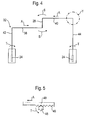
- FIGS. 4 and 5 show a second embodiment of the driving device 14.
- the entrainment device 14 is shown here as a linkage 32 with four rods 38, 40, 42, 44.
- the rods 38, 40 which are directly connected to the pivotable handle 28 (pivoting movement S) are formed as racks with a respective toothing 46.
- a toothed wheel 48 (see FIG. 5) which is provided on the rods 42, 44 can mesh in the respective toothing 46.
- the two locking elements 24 are arranged at the ends of the rods 42, 44.
- the handle 28 To couple the two blinds 10, 12 ( Figures 1a and 1b), the handle 28 must be pivoted back, causing the rods 38, 40 move counter to the direction A and the gears 48 rotate against the rotational movement T. As a result, the latching elements 24 are rotated and engage in the recesses 36.
- a coupling of the second roller blind 12 to the first roller blind 10 could also take place without actuation of the handle 28 with the aid of the resilient elements 26 and the insertion bevels 37 (shown in dashed lines in FIG Insertion bevels 37 could be provided adjacent to the recesses 36.
- FIGS. 6 and 7 show a third embodiment of the driving device 14.
- the locking element 24 and the handle 28 are provided on the front roller blind 10.
- the locking element 24 is formed like a pin and can engage in a recess 36 of a coupling rod 50.
- the coupling rod 50 is attached to the rear roller blind 10.
- the spring-loaded locking elements 24 can be pushed back against the spring force due to the insertion bevels 37 which are provided on the coupling rods 50 and then engage in the recesses 36, whereby the two blinds 10, 12 are coupled to each other.
- the handle 28 To decouple the two blinds 10, 12, the handle 28 must be pivoted (pivoting movement S). As a result, the two latching elements 24 are moved out of the recesses 36.
- the two blinds 10, 12 could also be coupled to one another via a pivoting movement of the handle 28.
- the driving device 14 of all embodiments could be part of a roller blind system whose roller blinds 10, 12 are in opposite directions.
- the winding bodies 20, 22 are arranged in the middle region of the opening, and the first roller blind 10 is pulled in the direction of travel F in order to cover the opening, and the second roller blind 12 is pulled counter to the direction of travel F in order to cover the opening.
Landscapes
- Engineering & Computer Science (AREA)
- Mechanical Engineering (AREA)
- Operating, Guiding And Securing Of Roll- Type Closing Members (AREA)
- Blinds (AREA)
Priority Applications (3)
| Application Number | Priority Date | Filing Date | Title |
|---|---|---|---|
| EP06009100A EP1852286A1 (fr) | 2006-05-02 | 2006-05-02 | Dispositif de connexion pour un store à enrouleur et système de store pour un toit de véhicule |
| US11/739,746 US20070256795A1 (en) | 2006-05-02 | 2007-04-25 | Entrainment device for a roller blind and roller blind system for a vehicle roof |
| CNA2007101071428A CN101066662A (zh) | 2006-05-02 | 2007-04-30 | 用于卷帘的夹卷装置和用于车辆顶篷的卷帘系统 |
Applications Claiming Priority (1)
| Application Number | Priority Date | Filing Date | Title |
|---|---|---|---|
| EP06009100A EP1852286A1 (fr) | 2006-05-02 | 2006-05-02 | Dispositif de connexion pour un store à enrouleur et système de store pour un toit de véhicule |
Publications (1)
| Publication Number | Publication Date |
|---|---|
| EP1852286A1 true EP1852286A1 (fr) | 2007-11-07 |
Family
ID=36954976
Family Applications (1)
| Application Number | Title | Priority Date | Filing Date |
|---|---|---|---|
| EP06009100A Withdrawn EP1852286A1 (fr) | 2006-05-02 | 2006-05-02 | Dispositif de connexion pour un store à enrouleur et système de store pour un toit de véhicule |
Country Status (3)
| Country | Link |
|---|---|
| US (1) | US20070256795A1 (fr) |
| EP (1) | EP1852286A1 (fr) |
| CN (1) | CN101066662A (fr) |
Cited By (2)
| Publication number | Priority date | Publication date | Assignee | Title |
|---|---|---|---|---|
| FR2955803A1 (fr) * | 2010-02-02 | 2011-08-05 | Acs France Sas | Dispositif d'occultation pour vehicule automobile, a actionnement deporte, et vehicule automobile correspondant. |
| DE202016106111U1 (de) | 2016-10-31 | 2017-01-04 | Roof Systems Germany Gmbh | Verschattungssystem für ein Fahrzeugdach sowie Fahrzeugfaltdachsystem |
Families Citing this family (5)
| Publication number | Priority date | Publication date | Assignee | Title |
|---|---|---|---|---|
| JP5391165B2 (ja) * | 2009-09-24 | 2014-01-15 | 八千代工業株式会社 | 車両のロールシェード装置 |
| KR101240988B1 (ko) * | 2010-12-07 | 2013-03-11 | 현대자동차주식회사 | 차량용 파노라마루프 장치 |
| KR101394724B1 (ko) * | 2012-10-30 | 2014-05-15 | 현대자동차주식회사 | 자동차의 파노라마 선루프용 롤블라인드 시스템 |
| DE102012220954A1 (de) * | 2012-11-16 | 2014-05-22 | Wacker Chemie Ag | Schleifbare Siliconelastomerzusammensetzung und deren Verwendung |
| DE102014211619B4 (de) * | 2013-06-28 | 2019-07-25 | Bos Gmbh & Co. Kg | Beschattungsvorrichtung für einen Glasflächenbereich eines Kraftfahrzeugs |
Citations (3)
| Publication number | Priority date | Publication date | Assignee | Title |
|---|---|---|---|---|
| DE10163122A1 (de) * | 2001-12-20 | 2003-07-10 | Bos Gmbh | Doppelrollo für gekrümmte Scheiben |
| DE10206161A1 (de) * | 2002-02-14 | 2003-09-11 | Webasto Vehicle Sys Int Gmbh | Öffnungsfähiges Fahrzeugdach mit mindestens einem Deckel und zwei Abdeckeinrichtungen |
| EP1353037A2 (fr) * | 2002-04-13 | 2003-10-15 | HAPPICH Fahrzeug- und Industrieteile GmbH | Store à rouleau de fenêtre |
Family Cites Families (11)
| Publication number | Priority date | Publication date | Assignee | Title |
|---|---|---|---|---|
| US1678229A (en) * | 1928-07-24 | Kino eabisi | ||
| US524712A (en) * | 1894-08-21 | Awning | ||
| US1841126A (en) * | 1930-12-13 | 1932-01-12 | Indeck Albert | Window screen operator |
| US2585769A (en) * | 1948-09-22 | 1952-02-12 | Lewis W Hamlin | Windshield visor |
| US2870831A (en) * | 1955-06-15 | 1959-01-27 | Peselnick Herman | Multipanel windows |
| CH595541A5 (fr) * | 1975-06-13 | 1978-02-15 | Louis Junod | |
| US5520236A (en) * | 1993-10-26 | 1996-05-28 | Speedling, Inc. | Greenhouse curtain system |
| WO2001094139A1 (fr) * | 2000-06-02 | 2001-12-13 | Webasto Vehicle Systems International Gmbh | Dispositif d'entrainement du pare-soleil du toit d'un vehicule automobile |
| IT1315679B1 (it) * | 2000-10-05 | 2003-03-14 | Nuova C G A Sistemi Srl | Parete di chiusura di area definita |
| US6561250B2 (en) * | 2001-08-08 | 2003-05-13 | Chanel, Inc. | Display device |
| DE10237231B3 (de) * | 2002-08-14 | 2004-02-19 | Bos Gmbh & Co. Kg | Fensterrollo mit bidirektional wirkenden Betätigungselementen |
-
2006
- 2006-05-02 EP EP06009100A patent/EP1852286A1/fr not_active Withdrawn
-
2007
- 2007-04-25 US US11/739,746 patent/US20070256795A1/en not_active Abandoned
- 2007-04-30 CN CNA2007101071428A patent/CN101066662A/zh active Pending
Patent Citations (3)
| Publication number | Priority date | Publication date | Assignee | Title |
|---|---|---|---|---|
| DE10163122A1 (de) * | 2001-12-20 | 2003-07-10 | Bos Gmbh | Doppelrollo für gekrümmte Scheiben |
| DE10206161A1 (de) * | 2002-02-14 | 2003-09-11 | Webasto Vehicle Sys Int Gmbh | Öffnungsfähiges Fahrzeugdach mit mindestens einem Deckel und zwei Abdeckeinrichtungen |
| EP1353037A2 (fr) * | 2002-04-13 | 2003-10-15 | HAPPICH Fahrzeug- und Industrieteile GmbH | Store à rouleau de fenêtre |
Cited By (2)
| Publication number | Priority date | Publication date | Assignee | Title |
|---|---|---|---|---|
| FR2955803A1 (fr) * | 2010-02-02 | 2011-08-05 | Acs France Sas | Dispositif d'occultation pour vehicule automobile, a actionnement deporte, et vehicule automobile correspondant. |
| DE202016106111U1 (de) | 2016-10-31 | 2017-01-04 | Roof Systems Germany Gmbh | Verschattungssystem für ein Fahrzeugdach sowie Fahrzeugfaltdachsystem |
Also Published As
| Publication number | Publication date |
|---|---|
| CN101066662A (zh) | 2007-11-07 |
| US20070256795A1 (en) | 2007-11-08 |
Similar Documents
| Publication | Publication Date | Title |
|---|---|---|
| EP1204539B1 (fr) | Dispositif d'entrainement du pare-soleil du toit d'un vehicule automobile | |
| EP1852286A1 (fr) | Dispositif de connexion pour un store à enrouleur et système de store pour un toit de véhicule | |
| EP2613953B1 (fr) | Dispositif d'ombrage pour une ouverture vitrée de véhicule | |
| DE102007057936A1 (de) | Türkantenschutzeinrichtung | |
| DE102017206449B4 (de) | Wohnwagenfenster und Öffnungsmechanismus dafür | |
| DE202017106376U1 (de) | Wohnwagenfenster und Öffnungsmechanismus dafür | |
| DE102007053531B4 (de) | Rolloeinrichtung | |
| DE19750715C1 (de) | Rollovorrichtung für ein Fahrzeugdach mit transparenter Dachscheibe | |
| EP1650068A2 (fr) | Panneau pour la construction de toit ouvrant | |
| DE102006042595A1 (de) | Anzeigeeinrichtung | |
| DE3639750A1 (de) | Vorrichtung zum hin- und herbewegen einer fensterscheibe | |
| DE10203904B4 (de) | Antriebsvorrichtung für Kraftfahrzeugschiebedächer | |
| DE112007001237T5 (de) | Vorrichtung zum Betätigen eines Sonnenschutzes | |
| DE102007006358A1 (de) | Schiebetüre für ein Kraftfahrzeug | |
| DE3427772C2 (de) | Rollo für einen ausstellbaren Glasdeckel im Dach eines Kraftfahrzeuges | |
| EP3310598B1 (fr) | Dispositif d'ombrage pour une vitre d'un véhicule automobile | |
| DE102012010999A1 (de) | Baukastensystem eines Schiebe- oder Hebedaches für Fahrzeugdächer sowie Verfahren zum Herstellen eines solchen Schiebe- oder Hebedaches für Fahrzeugdächer | |
| DE102016212165A1 (de) | Beschattungsvorrichtung für eine Scheibe eines Kraftfahrzeugs | |
| DE202007012981U1 (de) | Verstelleinrichtung für eine Abdeckvorrichtung in einem Kraftfahrzeug | |
| DE102008013067B4 (de) | Antriebsanordnung für ein Rollo, insbesondere für ein Sonnenschutzrollo eines Fahrzeugs | |
| DE1198239B (de) | Handbetaetigter Fensterheber fuer in den Fenster-schacht eines Kraftfahrzeugs versenkbare Schiebefenster | |
| DE10204360C1 (de) | Verstellbare Abdeckvorrichtung für einen transparenten Fahrzeugdachabschnitt | |
| DE102007021706B4 (de) | Antriebsvorrichtung für Verstelleinheiten in Fahrzeugtüren | |
| DE102018129520B4 (de) | Klappladen, Fassadenanordnung und Verfahren hierfür | |
| DE102017206905A1 (de) | Gepäckraumabdeckung und Abtrenneinrichtung |
Legal Events
| Date | Code | Title | Description |
|---|---|---|---|
| PUAI | Public reference made under article 153(3) epc to a published international application that has entered the european phase |
Free format text: ORIGINAL CODE: 0009012 |
|
| AK | Designated contracting states |
Kind code of ref document: A1 Designated state(s): AT BE BG CH CY CZ DE DK EE ES FI FR GB GR HU IE IS IT LI LT LU LV MC NL PL PT RO SE SI SK TR |
|
| AX | Request for extension of the european patent |
Extension state: AL BA HR MK YU |
|
| AKX | Designation fees paid | ||
| STAA | Information on the status of an ep patent application or granted ep patent |
Free format text: STATUS: THE APPLICATION IS DEEMED TO BE WITHDRAWN |
|
| 18D | Application deemed to be withdrawn |
Effective date: 20080508 |
|
| REG | Reference to a national code |
Ref country code: DE Ref legal event code: 8566 |