EP1850524A1 - Procédé d'allocation de sous-porteuses, station de base et terminal pour transmission MDFO - Google Patents
Procédé d'allocation de sous-porteuses, station de base et terminal pour transmission MDFO Download PDFInfo
- Publication number
- EP1850524A1 EP1850524A1 EP06290699A EP06290699A EP1850524A1 EP 1850524 A1 EP1850524 A1 EP 1850524A1 EP 06290699 A EP06290699 A EP 06290699A EP 06290699 A EP06290699 A EP 06290699A EP 1850524 A1 EP1850524 A1 EP 1850524A1
- Authority
- EP
- European Patent Office
- Prior art keywords
- sub
- carriers
- regions
- resource regions
- type
- Prior art date
- Legal status (The legal status is an assumption and is not a legal conclusion. Google has not performed a legal analysis and makes no representation as to the accuracy of the status listed.)
- Withdrawn
Links
Images


Classifications
-
- H—ELECTRICITY
- H04—ELECTRIC COMMUNICATION TECHNIQUE
- H04L—TRANSMISSION OF DIGITAL INFORMATION, e.g. TELEGRAPHIC COMMUNICATION
- H04L5/00—Arrangements affording multiple use of the transmission path
- H04L5/02—Channels characterised by the type of signal
- H04L5/06—Channels characterised by the type of signal the signals being represented by different frequencies
-
- H—ELECTRICITY
- H04—ELECTRIC COMMUNICATION TECHNIQUE
- H04L—TRANSMISSION OF DIGITAL INFORMATION, e.g. TELEGRAPHIC COMMUNICATION
- H04L5/00—Arrangements affording multiple use of the transmission path
- H04L5/003—Arrangements for allocating sub-channels of the transmission path
- H04L5/0037—Inter-user or inter-terminal allocation
-
- H—ELECTRICITY
- H04—ELECTRIC COMMUNICATION TECHNIQUE
- H04L—TRANSMISSION OF DIGITAL INFORMATION, e.g. TELEGRAPHIC COMMUNICATION
- H04L5/00—Arrangements affording multiple use of the transmission path
- H04L5/003—Arrangements for allocating sub-channels of the transmission path
- H04L5/0044—Arrangements for allocating sub-channels of the transmission path allocation of payload
- H04L5/0046—Determination of how many bits are transmitted on different sub-channels
-
- H—ELECTRICITY
- H04—ELECTRIC COMMUNICATION TECHNIQUE
- H04L—TRANSMISSION OF DIGITAL INFORMATION, e.g. TELEGRAPHIC COMMUNICATION
- H04L5/00—Arrangements affording multiple use of the transmission path
- H04L5/0001—Arrangements for dividing the transmission path
- H04L5/0003—Two-dimensional division
- H04L5/0005—Time-frequency
- H04L5/0007—Time-frequency the frequencies being orthogonal, e.g. OFDM(A), DMT
Definitions
- the present invention relates to a method of allocating sub-carriers for communication with at least one end terminal in OFDM transmission.
- the present invention also relates to a base station for use in OFDM transmission to at least one end terminal as well as to an end terminal, particularly a mobile station, for use in OFDM communication with a base station of the above-defined type.
- the present invention relates to a computer program product comprising program code sequences for downloading on a base station for use in OFDM transmission to at least one end terminal and / or for installing on an end terminal, particularly a mobile station, for use in OFDM communication with said base station.
- Frequency-Division Multiplexing In Frequency-Division Multiplexing (FDM), multiple signals are sent out at the same time, but in different frequencies.
- FDM Frequency-Division Multiplexing
- a single transmitter transmits on many (typically dozens to thousands) different orthogonal frequencies. These frequencies are also referred to as sub-carriers, the totality of available sub-carriers forming an OFDM spectrum.
- a (geographical) transmission area for OFDM transmission is subdivided into a number of OFDM transmission cells, each of them being served by a respective base station or NodeB.
- User equipment e.g. mobile stations
- present inside the OFDM transmission cells are allocated resources, i.e. sub-carriers, for communication inside the OFDM transmission system. Said allocation of resources is controlled by the base stations.
- the object is achieved by providing a method of the above-defined type, comprising the steps of:
- a base station for use in OFDM transmission to at least one end terminal comprising:
- the object is achieved by providing an end terminal, particularly a mobile station, for use in OFDM communication with a base station according to said second aspect of the present invention, said end terminal comprising means for establishing and / or maintaining said communication on the basis of the allocated sub-carriers.
- the object is achieved by providing a computer program product of the above-defined type, wherein said program code sequences implement on said base:
- said program code sequences enable performing the method in accordance with said first aspect of the present invention when executed on suitable data processing means comprised in base station and / or the at least one end terminal, respectively.
- the present invention achieves fast allocation of resources for communication with end terminals with only low signalling effort owing to an adaptable pre-definition of a resource structure, which can be further refined (adapted), e.g. for interference coordination purposes.
- said resource allocation can be performed in downlink and / or in uplink, i.e. resource allocation for communication with an end terminal (communication between a base station and said end terminal) can generally be performed under control of the base station and / or under control of the end terminal.
- the step of defining said first type resource regions includes equally spacing said first type resource regions.
- the step of defining said second type resource regions includes equally spacing said second type resource regions.
- the latter further comprises the step of adapting a size and / or spectral location of said first type resource regions and / or said second type resource regions in response to transmission-related information, e.g., traffic conditions, transmission reliability, signal quality or the like.
- transmission-related information e.g., traffic conditions, transmission reliability, signal quality or the like.
- the latter further comprises the step of defining at least respective parts of a number of said first type resource regions and /or at least respective parts of a number of said second type resource regions as having a specific OFDM transmission characteristic, particularly a reduced transmission power.
- a number of (whole) first and / or second type resource regions can be assigned a specific OFDM transmission characteristic.
- only parts of first and / or second type resource regions can be assigned a specific OFDM transmission characteristic. In this way, sub-carrier allocation can be achieved while taking into account a spatial distribution of end terminals in an OFDM transmission cell in terms of cell center vs. cell periphery.
- the latter further comprises the step of storing structure information concerning a resource structure formed by the defined first and second type resource regions at the at least one end terminal and / or at least one base station in operative connection with the end terminal.
- structure information concerning a resource structure formed by the defined first and second type resource regions at the at least one end terminal and / or at least one base station in operative connection with the end terminal.
- Optimum reduction of signalling effort is achieved if both base station and end terminal are in possession (i.e., store) said structure information.
- Fig. 1 is a schematic diagram of an OFDM transmission cell 1 as comprised in an OFDM transmission system 2 further comprising a number of additional transmission cells such as 1a - 1f.
- Transmission cell 1 (like substantially identical transmission cells 1a - 1f) comprises a base station 3 and a number of end terminals (user equipment (UE), preferably mobile stations) 4.1 - 4.3 operatively connected for communication purposes with base station 3 via respective radio links 5.1 - 5.3.
- UE user equipment
- base station 3 is connected with a central node 6 of OFDM transmission system 2, said central node also being referred to as Operations Maintenance Center (OMC) or Operations & Maintenance (O&M).
- OMC Operations Maintenance Center
- O&M Operations & Maintenance
- base station 3 For communication within the OFDM transmission system 2, base station 3 defines and allocates (radio) resources to individual end terminals 4.1 - 4.3 present inside the associated transmission cell 1.
- OMC 6 functions as a control unit for controlling operation of base station 3, e.g. by providing software, i.e. program code sequences for installing on base station 3 as well as on end terminals 4.1 - 4.3.
- the software can be provided by downloading from the base station 3 or it can be preinstalled.
- Fig. 2 is a schematic block diagram of a base station 3 used in the OFDM transmission system 2 of Fig. 1.
- Base station 3 generally comprises data processing means 3a and storage means 3b.
- base station 3 further comprises first partitioning means 3c, second partitioning means 3d, first selecting means 3e, second selecting means 3f, allocating means 3g, and broadcasting means 3h.
- Means 3c - 3h are preferably devised at least partly in software form by means of software downloaded from OCM 6 (Fig. 1).
- Corresponding program code sequences and further operational information provided by OMC 6 are stored in storage means 3b.
- First partitioning means 3c are adapted for partitioning a spectrum of sub-carriers available for OFDM transmission into mutually spaced resource regions of a first type, each of said regions comprising a number of consecutives sub-carriers for a number of consecutive OFDM symbols.
- second partitioning means 3d are adapted for partitioning a remaining part of the available OFDM sub-carrier spectrum into mutually spaced resource regions of a second type, each of said regions comprising a number of consecutive sub-carriers for a number of consecutive OFDM symbols.
- Said first type resource regions will hereinafter also be referred to as “resource group regions”, and said second type resource regions will hereinafter also be referred to as “resource block regions”.
- First selecting means 3e are adapted for choosing or selecting a number of mutually isolated or mutually adjacent sub-carriers from at least one of said first type resource regions, i.e. resource group regions, for distributed sub-carrier allocation. Such sub-carriers will hereinafter also be referred to as a "resource group”.
- the second selecting means 3f are adapted for choosing (selecting) a number of mutually adjacent sub-carriers from at least one of said second type resource regions, i.e. resource block regions, for localised sub-carrier allocation. Such sub-carriers will hereinafter also be referred to as a "resource block”.
- Allocating means 3g are adapted for allocating chosen / selected sub-carriers to the end terminals 4.1 - 4.3 (Fig. 1).
- Any information on resource region definition, sub-carrier selection and / or sub-carrier allocation can be communicated to the end terminals 4.1 - 4.3 by means of broadcasting means 3h, preferably in broadcasting mode.
- Fig. 3 is a schematic block diagram of an exemplary one of end terminals 4.1 - 4.3 in Fig. 1 which is generally denoted 4 in Fig. 3.
- the end terminal 4 of Fig. 3 which can advantageously be devised as a mobile station for use in OFDM communication with the base station of Fig. 2, generally comprises data processing means 4a and storage means 4b. Within data processing means 4a, end terminal 4 further comprises receiving means 4c and communication establishing / maintaining means 4d. Means 4c, 4d are preferably devised at least partly in software form, wherein corresponding program code sequences can be downloaded from base station 3 (Fig. 2) or from OCM 6 (Fig. 1) via base station 3 and are stored in storage means 4b.
- Communication establishing / maintaining means 4d are adapted for establishing /or maintaining an OFDM communication with the base station 3 (Fig. 2) on the basis of allocated sub-carriers.
- Receiving means 4c are adapted for receiving broadcast information from base station 3 (Fig. 2).
- Fig. 4 is a schematic diagram of a sub-carrier spectrum used for OFDM transmission in the OFDM transmission system 2 of Fig. 1.
- a bandwidth BW available for OFDM transmission and including a number of control channels is subdivided into a number of sub-carriers SC (ranging from SC0 to SCn, generally referred to as SCi).
- Sub-carriers SCi are used for transmission of consecutive OFDM symbols in time, a time coordinate being denoted t in Fig. 4.
- SCi sub-carriers
- different sub-carriers SCi generally have different transmission qualities due to, e.g., interference or different transmission paths with different qualities.
- End terminals 4.1 - 4.3 (Fig. 1) are assigned sub-carriers SCi by base station 3 for use in OFDM communication, i.e., they are allocated sub-carriers or resources.
- localised allocation LA involves blockwise allocation of sub-carriers according to their quality.
- Blockwise (localised) allocation of sub-carriers can alternatively be referred to as allocating a number of mutually adjacent sub-carriers.
- distributed allocation DAi involves allocating sub-carriers which are spread broadly over the available bandwidth BW in an ideally but not necessarily equidistant fashion.
- the distributed allocation scheme is advantageously used if, e.g., channel quality measurement is not reliable enough for localised allocation.
- Fig. 4 shows an example for distributed allocation using three sub-carriers at DA1 - DA3.
- distributed allocation of sub-carriers SCi is also referred to as allocating a number of mutually isolated sub-carriers or as allocating a number of mutually adjacent sub-carriers provided that they are non-consecutive.
- Fig. 5 shows a schematic diagram of a first example of sub-carrier allocation using an embodiment of the method in accordance with the present invention. Note that the time t and sub-carrier SCi axes have been flipped with respect to the diagram of Fig. 4.
- the available spectrum of OFDM sub-carriers as depicted in Fig. 4 is partitioned into a number of mutually spaced resource regions of a first type and of a second type, respectively.
- said first type regions are referred to as resource group regions.
- Resource group regions form part of the whole available bandwidth BW (Fig. 4) and comprise a number of consecutive sub-carriers SCi for a number of consecutive time symbols, i.e. consecutive OFDM symbols in time.
- RGRi resource group regions
- xRGR common size in terms of comprised sub-carriers
- yRGR > xRGR sub-carriers
- Resource block regions RBRi are used for localised allocation of sub-carriers.
- resource groups RGi and resource blocks RBi are the smallest resource units used for allocation.
- a resource group RGj consists of a number of non-consecutive, preferably, equally spaced single or consecutive sub-carriers for a number of consecutive time symbols. Resource groups such as RGj are used for a distributed allocation within resource group regions (RGRi).
- RGRi resource group regions
- Resource blocks RBj consists of a number of consecutive sub-carriers for a number of consecutive time symbols. Resource blocks RBj are used for localised allocation within resource block regions RBRi.
- Fig. 6 shows a schematic diagram of a defined resource structure for sub-carrier allocation in accordance with the present invention.
- first and second type resource regions i.e. resource group regions and resource block regions, respectively
- a number of said first type regions and / or second type regions or respective parts of a number of said first type regions and/or second type regions can be associated with at least one specific OFDM transmission characteristic, for instance a reduced transmission power.
- resource group regions and resource block regions with reduced transmission power are referred to as low power regions LRi
- resource group regions and resource block regions with normal transmission power are referred to as normal power regions NRi.
- respective parts of resource regions can be assigned specific transmission-related characteristics. For instance, for interference coordination individual resource groups instead of entire resource regions can be assigned for transmission with reduced transmission power.
- a first low power region LR1 includes resource group region RGR1 (SC0, SC1) and resource group region RGR2 (SC18, SC19) as well as resource block region RBR1 encompassing sub-carriers SC2 to SC17.
- Subsequent normal power region NR1 includes resource group regions RGR3, RGR4 and resource block region RBR2 encompassing sub-carriers SC20-SC21, SC38-SC39, and SC22 to SC37, respectively.
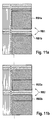
- Fig. 7 shows a schematic diagram of an adapted defined resource structure for sub-carrier allocation in accordance with the present invention.
- Resource structure of Fig. 7 is based on the previously described structure of Fig. 6, the latter having, e.g., being adapted for reasons of required additional distributed allocation. Such an allocation may be required due to changing traffic conditions inside OFDM transmission cell 1 (Fig. 1).
- the adapted resource structure of Fig. 7 comprises low power region LR1 and normal power region NR1, as previously defined with reference to Fig. 6.
- resource group region RGR1 now comprises sub-carriers SC0 to SC2
- resource group region RGR2 now comprises sub-carriers SC17 to SC19. Consequently, resource block region RBR1 has been reduced to comprising sub-carriers SC3 to SC16 only.
- resource group region RGR3 now comprises sub-carriers SC20 to SC22
- resource group region RGR4 now comprises sub-carriers SC37 to SC39. Consequently, resource block region RBR2 has been reduced to comprising sub-carriers SC23 to SC36 only. This is equivalent to saying that a size of said first type regions and / or said second type regions is adapted in response to transmission-related information.
- Fig. 8 shows a schematic diagram of a further adapted resource structure for sub-carrier allocation in accordance with the present invention.
- low power region LR1 comprises a first resource group region RGR1 and a second resource group region RGR2 encompassing sub-carriers SC0, SC1 and SC18, SC19, respectively.
- a normal power region NR1 comprises a third resource group region RGR3 and a fourth resource group region RGR4 encompassing sub-carriers SC20, SC21 and SC38, SC39, respectively.
- the resource structure of Fig. 8 comprises an additional resource group region RGR5 (sub-carriers SC9, SC10) in low power region LR1 and a further resource group region RGR6 (sub-carriers SC29, SC30) in normal power region LR1.
- Fig. 9 shows a schematic diagram of a further example of sub-carrier allocation using the method in accordance with the present invention.
- sub-carriers SC0 to SC11 constitute low power region LR1
- sub-carriers SC36 to SC47 constitute low power region LR2.
- Sub-carriers SC12 to SC23 constitute normal power region NR1
- sub-carriers SC24 to SC35 constitute normal power region NR2, i.e. normal power region NR.
- Sub-carriers SC48 to SC59 constitute normal power region NR3
- sub-carriers SC60 to SC71 constitute normal power region NR4, i.e. normal power region NR'.
- Each power region LRi, NRi comprises a number of resource group regions RGRi and a number of resource block regions RBRj, as explained in detail above.
- one or more resource groups RGj of the given size are allocated in one or more resource group regions RGRi within a low power region LRi and / or within a normal power region NRi.
- resource block size is ten sub-carriers.
- Resource group size is two sub-carriers for low power regions and four sub-carriers for normal power regions.
- One resource block RB1 with ten sub-carriers SC2 to SC11 is allocated in one resource block region RBR1 within low power region LR1.
- One resource group RG1 comprising four sub-carriers SC13, SC25, SC49 and SC61 is allocated in four resource group regions RGR2, RGR3, RGR5, RGR6 within four different normal power regions NR1 - NR4.
- Fig. 10 shows a schematic diagram of a further example of sub-carrier allocation using the method in accordance with the present invention.
- resource block size is again ten sub-carriers.
- a resource group size comprises two sub-carriers for low power regions LR1, LR2 and two sub-carriers for each of normal power regions LR1 - LR4.
- two resource blocks RB1, RB2 comprising ten sub-carriers each (SC26 to SC35 and SC62 to SC71, respectively) are allocated in two resource block regions RBR3, RBR6 within two normal power regions NR2, NR4.
- two resource groups RG1, RG2 with two sub-carriers each (SC0, SC36 and SC1, SC37, respectively) are allocated in two resource group regions RGR1, RGR4 within two low power regions LR1, LR2.
- resource blocks generally comprise a number of consecutive sub-carriers (arranged in blockwise fashion) for a number of consecutive OFDM symbols in time.
- a sequence formed by consecutive sub-carriers within a resource block can be interrupted by successive resource group sub-carriers, i.e. sub-carriers defined as belonging to a resource group region.
- Two different general cases can be distinguished in this context, which are illustrated in appended Figs. 11 a, 11 b.
- Figs. 11 a, b show schematic diagrams of examples of resource region definition using an embodiment of the method in accordance with the present invention.
- resource block RB1 comprising sub-carriers SC3 to SC11 and SC14 is interrupted by resource group sub-carriers SC12, SC13.
- the resource block size is not reduced by the number of interrupting resource group sub-carriers in the case of Fig. 11 a.
- resource block RB2 which is interrupted by successive resource groups sub-carriers SC36, SC37, is reduced in size by the number of interrupting resource group sub-carriers, i.e., the resource block size of resource block RB2 is only eight instead of ten sub-carriers.
- a nominal resource block size is ten sub-carriers.
- resource block RB2 which is interrupted by two successive sub-carriers SC36, SC37 belonging to (two different) resource groups, is split up into a resource block part RB2a including five sub-carriers SC31 to SC35 and a resource block part RB2b consisting of three sub-carriers SC38 to SC40.
- Said resource block parts RB2a, RB2b can be allocated within any combination of low and normal power regions, as required.
- resource block RB1 which is interrupted by two successive sub-carriers SC12, SC13 belonging to two resource groups, is split up into a resource block part RB1a including nine sub-carriers SC3 to SC11 and a resource block part RB1 b consisting of only one sub-carrier SC14.
- resource block parts RB1 a, RB1 b can be allocated in two resource block regions within any combination of low and normal power regions, as required.
- Fig. 12 shows a flow chart for illustrating signalling used in the context of an embodiment of the method in accordance with the present invention.
- the signalling involving processing of resource structure information as described below with reference to Fig. 12 is specifically related to the exemplary resource structure described above with reference to Fig. 5.
- system type information comprising, e.g., a total number of available sub-carriers and positions of control channels (not shown) is known to the signalling parties, i.e. base station 3 and end terminals 4.1 - 4.3 (Fig. 1).
- step S100 a first amount of information is broadcast from base station 3 (Fig. 1, 2) to end terminals 4.1 - 4.3 present inside transmission cell 1 (Fig. 1) by means of broadcasting means 3h (Fig. 2).
- Said first amount of broadcast information comprises data descriptive of a definition of the resource group size, e.g. 20 sub-carriers.
- a further amount of information is broadcast to the end terminals, said information comprising data descriptive of a position (spectral location) of a first resource group region defined in terms of a specific sub-carrier, e.g. sub-carrier SC20.
- information concerning a size of individual resource group regions is broadcast from base station 3 (Fig. 1) to end terminals 4.1 - 4.3. Sizes of individual resource group regions are defined in terms of a number of comprised sub-carriers, e.g. seven.
- step S108 positions (spectral locations) of all resource group regions are calculated based on the above-defined broadcast information.
- step S110 positions (spectral locations) of all resource block regions are determined based on said broadcast information, too.
- the signalling parties i.e. base station 3 and end terminals 4.1 - 4.3 (Fig. 1) may comprise corresponding calculating / determining means (not shown) within their respective data processing means 3a (Fig. 2) and 4a (Fig. 3), respectively.
- Said calculating / determining means are preferably devised in software form.
- step S112 At least said calculated spectral locations are stored as a resource structure in the storing means 3b, 4b of both base station 3 and end terminals 4.1 - 4.3, respectively.
- step S114 At least said calculated spectral locations are stored as a resource structure in the storing means 3b, 4b of both base station 3 and end terminals 4.1 - 4.3, respectively.
- step S114 terminates with step S114.
- sizes or portions of individual resource regions may be limited with respect to both pre-definition and adaptation.
- a resource block region may be limited to covering at least ten sub-carriers.
- a portion of resource group regions may be limited to 60% of a total number of sub-carriers available for OFDM transmission.
- positions of the resource regions may be pre-defined. For instance, resource group regions may be limited to being positioned at the beginning of each power region, i.e. lowest sub-carrier numbers in each power region.
Landscapes
- Engineering & Computer Science (AREA)
- Signal Processing (AREA)
- Computer Networks & Wireless Communication (AREA)
- Mobile Radio Communication Systems (AREA)
Priority Applications (1)
| Application Number | Priority Date | Filing Date | Title |
|---|---|---|---|
| EP06290699A EP1850524A1 (fr) | 2006-04-28 | 2006-04-28 | Procédé d'allocation de sous-porteuses, station de base et terminal pour transmission MDFO |
Applications Claiming Priority (1)
| Application Number | Priority Date | Filing Date | Title |
|---|---|---|---|
| EP06290699A EP1850524A1 (fr) | 2006-04-28 | 2006-04-28 | Procédé d'allocation de sous-porteuses, station de base et terminal pour transmission MDFO |
Publications (1)
| Publication Number | Publication Date |
|---|---|
| EP1850524A1 true EP1850524A1 (fr) | 2007-10-31 |
Family
ID=36753929
Family Applications (1)
| Application Number | Title | Priority Date | Filing Date |
|---|---|---|---|
| EP06290699A Withdrawn EP1850524A1 (fr) | 2006-04-28 | 2006-04-28 | Procédé d'allocation de sous-porteuses, station de base et terminal pour transmission MDFO |
Country Status (1)
| Country | Link |
|---|---|
| EP (1) | EP1850524A1 (fr) |
Cited By (3)
| Publication number | Priority date | Publication date | Assignee | Title |
|---|---|---|---|---|
| WO2009120118A1 (fr) * | 2008-03-25 | 2009-10-01 | Telefonaktiebolaget Lm Ericsson (Publ) | Procédés et dispositifs pour la signalisation de flux de données modulées multiples |
| CN101505209B (zh) * | 2008-02-04 | 2013-01-16 | 中兴通讯股份有限公司 | 信息发送方法和装置 |
| CN101505210B (zh) * | 2008-02-04 | 2013-05-01 | 中兴通讯股份有限公司 | 信息发送方法及装置 |
Citations (4)
| Publication number | Priority date | Publication date | Assignee | Title |
|---|---|---|---|---|
| EP1137212A1 (fr) * | 1999-10-04 | 2001-09-26 | Mitsubishi Denki Kabushiki Kaisha | Procede et dispositif de communication |
| WO2002049306A2 (fr) * | 2000-12-15 | 2002-06-20 | Broadstorm Telecommunications, Inc. | Communications a ondes porteuses multiples avec attribution d'ondes porteuses basee sur des groupes |
| WO2004077777A1 (fr) * | 2003-02-28 | 2004-09-10 | Nortel Networks Limited | Repartition de sous-porteuses pour le mrof |
| EP1526674A1 (fr) * | 2003-10-21 | 2005-04-27 | Alcatel | Méthode pour l'allocation des sous-porteuses et pour la sélection du schéma de modulation dans un système de transmission multiporteuse sans fil |
-
2006
- 2006-04-28 EP EP06290699A patent/EP1850524A1/fr not_active Withdrawn
Patent Citations (4)
| Publication number | Priority date | Publication date | Assignee | Title |
|---|---|---|---|---|
| EP1137212A1 (fr) * | 1999-10-04 | 2001-09-26 | Mitsubishi Denki Kabushiki Kaisha | Procede et dispositif de communication |
| WO2002049306A2 (fr) * | 2000-12-15 | 2002-06-20 | Broadstorm Telecommunications, Inc. | Communications a ondes porteuses multiples avec attribution d'ondes porteuses basee sur des groupes |
| WO2004077777A1 (fr) * | 2003-02-28 | 2004-09-10 | Nortel Networks Limited | Repartition de sous-porteuses pour le mrof |
| EP1526674A1 (fr) * | 2003-10-21 | 2005-04-27 | Alcatel | Méthode pour l'allocation des sous-porteuses et pour la sélection du schéma de modulation dans un système de transmission multiporteuse sans fil |
Cited By (4)
| Publication number | Priority date | Publication date | Assignee | Title |
|---|---|---|---|---|
| CN101505209B (zh) * | 2008-02-04 | 2013-01-16 | 中兴通讯股份有限公司 | 信息发送方法和装置 |
| CN101505210B (zh) * | 2008-02-04 | 2013-05-01 | 中兴通讯股份有限公司 | 信息发送方法及装置 |
| WO2009120118A1 (fr) * | 2008-03-25 | 2009-10-01 | Telefonaktiebolaget Lm Ericsson (Publ) | Procédés et dispositifs pour la signalisation de flux de données modulées multiples |
| US8681720B2 (en) | 2008-03-25 | 2014-03-25 | Telefonaktiebolaget L M Ericsson (Publ) | Methods and devices for multiple modulated data streams signaling |
Similar Documents
| Publication | Publication Date | Title |
|---|---|---|
| US11991100B2 (en) | Localized and distributed transmission | |
| US10938450B2 (en) | Base station router for distributed antenna systems | |
| CN102804833B (zh) | 共享或共同使用geran移动无线接入网络的方法、系统和基站 | |
| EP1715709B1 (fr) | Procede d'acces aleatoire et dispositif de terminal de radiocommunication | |
| US8031670B2 (en) | Systems and methods for selecting the size of a control region of a downlink subframe | |
| EP1855434B1 (fr) | Attribution de ressources pour une communication OFDM avec partition des multiporteuses et échange mutuelle de porteuses entre stations de base | |
| CN106134125B (zh) | 小小区资源分配 | |
| DK1847142T3 (en) | APPARATUS AND PROCEDURE FOR DYNAMIC ALLOCATION OF ORTHOGONAL CODES IN ETHRADIO-COMMUNICATION SYSTEM | |
| CN101406082A (zh) | 单载波频分多址系统中的相邻小区干扰管理 | |
| CN107615875B (zh) | 用于分割通信网络中的信号处理链的方法和系统 | |
| EP1850524A1 (fr) | Procédé d'allocation de sous-porteuses, station de base et terminal pour transmission MDFO | |
| EP2031907A1 (fr) | Procédé de signalisation | |
| EP1087630A1 (fr) | Procéde d'allocation de canal dynamique avec réarrangement dans un réseau radio TDD/AMRC et système correspondant | |
| CN105682101B (zh) | 一种信道占用的判决方法及判决装置 | |
| TW201448653A (zh) | 通訊控制裝置、通訊控制方法及資訊處理裝置 | |
| EP2410805A1 (fr) | Système de communication, appareil de communication, et procédé d'allocation de fréquences | |
| CA3004698A1 (fr) | Procede et dispositif d'attribution de ressource | |
| CN109561509B (zh) | 一种无线通讯系统反向资源分配的方法及装置 | |
| CN105007147B (zh) | 一种无线通信方法、装置及系统 | |
| JP2004172737A (ja) | 時分割多重伝送装置 | |
| CN116193610A (zh) | 降低小区间干扰的方法及装置 | |
| JP2002281544A (ja) | Cdmaチャネル設定装置およびcdma基地局制御装置 |
Legal Events
| Date | Code | Title | Description |
|---|---|---|---|
| PUAI | Public reference made under article 153(3) epc to a published international application that has entered the european phase |
Free format text: ORIGINAL CODE: 0009012 |
|
| AK | Designated contracting states |
Kind code of ref document: A1 Designated state(s): AT BE BG CH CY CZ DE DK EE ES FI FR GB GR HU IE IS IT LI LT LU LV MC NL PL PT RO SE SI SK TR |
|
| AX | Request for extension of the european patent |
Extension state: AL BA HR MK YU |
|
| 17P | Request for examination filed |
Effective date: 20080502 |
|
| 17Q | First examination report despatched |
Effective date: 20080530 |
|
| AKX | Designation fees paid |
Designated state(s): AT BE BG CH CY CZ DE DK EE ES FI FR GB GR HU IE IS IT LI LT LU LV MC NL PL PT RO SE SI SK TR |
|
| STAA | Information on the status of an ep patent application or granted ep patent |
Free format text: STATUS: THE APPLICATION IS DEEMED TO BE WITHDRAWN |
|
| 18D | Application deemed to be withdrawn |
Effective date: 20081010 |