EP1850252A1 - Automatic hose and harness routing method and system - Google Patents
Automatic hose and harness routing method and system Download PDFInfo
- Publication number
- EP1850252A1 EP1850252A1 EP07008607A EP07008607A EP1850252A1 EP 1850252 A1 EP1850252 A1 EP 1850252A1 EP 07008607 A EP07008607 A EP 07008607A EP 07008607 A EP07008607 A EP 07008607A EP 1850252 A1 EP1850252 A1 EP 1850252A1
- Authority
- EP
- European Patent Office
- Prior art keywords
- desired path
- path
- processor
- point
- end point
- Prior art date
- Legal status (The legal status is an assumption and is not a legal conclusion. Google has not performed a legal analysis and makes no representation as to the accuracy of the status listed.)
- Withdrawn
Links
Images

Classifications
-
- G—PHYSICS
- G06—COMPUTING; CALCULATING OR COUNTING
- G06F—ELECTRIC DIGITAL DATA PROCESSING
- G06F17/00—Digital computing or data processing equipment or methods, specially adapted for specific functions
- G06F17/10—Complex mathematical operations
-
- G—PHYSICS
- G06—COMPUTING; CALCULATING OR COUNTING
- G06F—ELECTRIC DIGITAL DATA PROCESSING
- G06F30/00—Computer-aided design [CAD]
- G06F30/10—Geometric CAD
- G06F30/15—Vehicle, aircraft or watercraft design
-
- G—PHYSICS
- G06—COMPUTING; CALCULATING OR COUNTING
- G06F—ELECTRIC DIGITAL DATA PROCESSING
- G06F30/00—Computer-aided design [CAD]
- G06F30/10—Geometric CAD
- G06F30/18—Network design, e.g. design based on topological or interconnect aspects of utility systems, piping, heating ventilation air conditioning [HVAC] or cabling
-
- B—PERFORMING OPERATIONS; TRANSPORTING
- B33—ADDITIVE MANUFACTURING TECHNOLOGY
- B33Y—ADDITIVE MANUFACTURING, i.e. MANUFACTURING OF THREE-DIMENSIONAL [3-D] OBJECTS BY ADDITIVE DEPOSITION, ADDITIVE AGGLOMERATION OR ADDITIVE LAYERING, e.g. BY 3-D PRINTING, STEREOLITHOGRAPHY OR SELECTIVE LASER SINTERING
- B33Y50/00—Data acquisition or data processing for additive manufacturing
-
- G—PHYSICS
- G06—COMPUTING; CALCULATING OR COUNTING
- G06F—ELECTRIC DIGITAL DATA PROCESSING
- G06F2111/00—Details relating to CAD techniques
- G06F2111/06—Multi-objective optimisation, e.g. Pareto optimisation using simulated annealing [SA], ant colony algorithms or genetic algorithms [GA]
-
- G—PHYSICS
- G06—COMPUTING; CALCULATING OR COUNTING
- G06F—ELECTRIC DIGITAL DATA PROCESSING
- G06F2113/00—Details relating to the application field
- G06F2113/14—Pipes
-
- G—PHYSICS
- G06—COMPUTING; CALCULATING OR COUNTING
- G06F—ELECTRIC DIGITAL DATA PROCESSING
- G06F2113/00—Details relating to the application field
- G06F2113/16—Cables, cable trees or wire harnesses
Definitions
- This disclosure relates generally to computer based design techniques and, more particularly, to methods and systems for automatic hose and harness routing.
- Modem structural assemblies may be designed to be compact and cost efficient.
- the structural assemblies associated with hoses and/or harnesses often include wirings, cables, pipes, and other specific lines for purposes such as control, communication, fluid power or hydraulics, etc. Because a particular structure may only support a certain types of configuration of the hoses or harnesses, it may be desired to consider the routing of the hoses or harnesses during the design process of the structural assemblies such that the hoses may be aligned properly.
- One aspect of the present disclosure includes a method for automatic hose and harness routing.
- the method may include obtaining a solid model of a structural design of a structure assembly and deriving a mathematical representation of the solid model.
- the method may also include selecting at least a pair of connection points including a start point and an end point and determining a desired path between the start point and the end point. Further, the method may include performing a validity check on the desired path to decide whether the desired path is valid and presenting the desired path.
- the method may include selecting a plurality of pairs of connection points and starting a genetic algorithm with a priority among the plurality of pairs of connection points.
- the method may also include determining a respective plurality of desired paths for the plurality of pairs of connection points in sequence according to the priority and calculating a total cost of the plurality of desired paths. Further, the method may include determining whether the total cost is below a predetermined threshold and completing the genetic algorithm if the total cost is below the predetermined threshold.
- the computer system may include a processor and a database.
- the processor may be configured to obtain a solid model of a structural design of a structure assembly and to derive a mathematical representation of the solid model.
- the processor may also be configured to select at least a pair of connection points including a start point and an end point and determine a desired path between the start point and the end point. Further, the processor may be configured to perform a validity check on the desired path to decide whether the desired path is valid, and the database may be configured to store the desired path by the processor.
- Another aspect of the present disclosure includes a computer-readable medium for use on a computer system configured to perform automatic hose and harness routing, the computer-readable medium having computer-executable instructions for performing a method.
- the method may include obtaining a solid model of a structural design of a structure assembly and deriving a mathematical representation of the solid model.
- the method may also include selecting at least a pair of connection points including a start point and an end point and determining a desired path between the start point and the end point. Further, the method may include performing a validity check on the desired path to decide whether the desired path is valid and presenting the desired path.
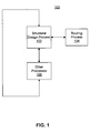
- Fig. 1 illustrates a block diagram of an exemplary automatic hose and harness routing environment 100. As shown in Fig. 1, a structural design process 102 is coupled with a routing process 104. Structural design process 102 may also be coupled with other processes 106.
- Structural design process 102 may be provided to perform computer based design processes related to a particular structural assembly.
- a structural assembly may refer to any product or component of a product that includes one or more physical structures.
- a structural assembly may include a vehicle, such as cars, trucks, construction vehicles, aircraft, etc., machines, factories, equipment, and/or consumer products, such as appliances, electronics, etc.
- a structural assembly may also include a component of a product, such as a circuit board of an electronic product, or a load bearing assembly of a construction vehicle, etc.
- a structural assembly may also include hoses and harnesses to be routed through the structural assembly or attached to certain surfaces of the structural assembly.
- hoses and harnesses may refer to any appropriate type of physical lines of certain materials.
- the hoses and harnesses may include wirings, cables, pipes, electrical harnesses, hydraulic lines, metal connections in printed circuit boards (PCB), etc.
- Structural design process 102 may perform various structural design processes to generate a structural design of a particular structure assembly.
- the structural design may be represented in any appropriate computer recognizable data form, such as forms used by a CAD software program.
- the structural design may also be provided to other processes 106 to improve the structural design or to use the structural design for other purposes, such as integrating the structural design into a complete product or into other products, etc.
- Other processes 106 may include one or more processes for performing any appropriate type of design functionality together with structural design process 102.
- Other processes 106 may modify the structural design created by structural design process 102 and may provide the modifications back to structural design process 102. Other processes 106 may also send required modifications to structural design process 102 without making actual modification. And structural design process 102, after receiving modification requirements from other processes 106, may change the structural design accordingly. Therefore, a new version of the structural design may be generated. Such interactions between structural design process 102 and other process 106 may continue until the structural design is finalized.
- structural design process 102 may provide the structural design to routing process 104 for automatically performing hose and harness routing for the structural design.
- Routing process 104 may perform hose and harness routing based on the structural design and other appropriate type of information, such as geometric constraints of the structural design, physical size requirement for the hoses or harnesses, and/or schematic information containing information on starting points, ending points, and/or passing points of various hoses and harnesses as well as performance requirements associated with the schematic, such as current drop, voltage drop, pressure losses, and/or flow rates, etc.
- Routing process 104, structural design process 102, and/or other processes 106 may be carried out by one or more computer systems.
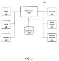
- Fig. 2 shows a functional block diagram of an exemplary computer system 200 that may be used to perform these processes.
- computer system 200 may include a processor 202, a random access memory (RAM) 204, a read-only memory (ROM) 206, a console 208, an input device 210, a network interface 212, a databases 214, and a storage 216. It is understood that the type and number of listed devices are exemplary only and not intended to be limiting. The number of listed devices may be changed and other devices may be added.
- RAM random access memory
- ROM read-only memory
- Processor 202 may include any appropriate type of general purpose microprocessor, digital signal processor, or microcontroller. Processor 202 may execute sequences of computer program instructions to perform various processes as explained above. The computer program instructions may be loaded into RAM 204 for execution by processor 202 from a read-only memory (ROM), or from storage 216.
- Storage 216 may include any appropriate type of mass storage provided to store any type of information that processor 202 may need to perform the processes, such as the computer program instructions and/or various data.
- storage 216 may include one or more hard disk device, floppy disk, optical disk device, or other storage device to provide storage space.
- Console 208 may provide a graphic user interface (GUI) to display or present information to users of computer system 200.
- GUI graphic user interface
- Console 208 may include any appropriate type of computer display device or computer monitor.
- Input device 210 may be provided for users to input information into computer system 200.
- Input device 210 may include a keyboard, a mouse, or other optical or wireless computer input devices, etc.
- network interface 212 may provide communication connections such that computer system 200 may be accessed remotely through computer networks via various communication protocols, such as transmission control protocol/internet protocol (TCP/IP), hyper text transfer protocol (HTTP), etc.
- TCP/IP transmission control protocol/internet protocol
- HTTP hyper text transfer protocol
- Database 214 may contain model data and/or any information related to the processes, such as configuration data, algorithm data, structural parameters, and/or any other design data, etc.
- Database 214 may include any type of commercial or customized database.
- Database 214 may also include analysis tools for analyzing the information in the database.
- Processor 202 may use database 214 to determine and store performance characteristics of the processes.
- processor 202 may perform routing process 104 to automatically find routing paths for a structural design generated by structural design process 102.
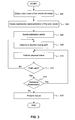
- Fig. 3 shows a flowchart diagram of an exemplary automatic hose and harness routing process performed by processor 202.
- processor 202 may obtain a solid model of a structural design (step 302).
- a solid model may refer to any structural design model that reflects physical characteristics of structures included in the model and space relationships among the structures.
- Processor 202 may obtain the solid model from structural design process 102.
- Processor 202 may also obtain the solid model from any appropriate design applications running on computer system 200 and/or from other computer systems or design applications.
- processor 202 may derive a mathematic representation or representations of the solid model (step 304).
- processor 202 may use any appropriate mathematic format to represent the solid model.
- processor 202 may use a stereo lithography (STL) tessellated format to represent the solid model.
- STL stereo lithography
- the STL format defines surfaces of a solid object as a set of adjacent triangles.
- the tessellated format defines that each edge is shared only by two triangles.
- the solid object may be represented by X, Y, Z Cartesian coordinates of each vertex of the triangles and coordinates of normal vectors to the triangles, with each edge being shared by two triangles. These 3D coordinates may be included in an ASCII or binary file to be used by various software application programs.
- the accuracy of the STL tessellated format may depend on the number of triangles representing a solid model. A larger number of triangles may provide a higher accuracy.
- Processor 202 may select connection points through which the hoses and harnesses are to be routed (step 306).
- processor 202 may select connection points in pairs.
- processor 202 may select a pair of connection points to be routed.
- Hose and harness routing may be realized by selecting a desired path between the pair of connection points.
- the pair of connection points may include a start point and an end point.
- the hoses and harnesses may be provided between the start point and the end point based on the STL format representation of the solid model. Further, multiple pairs of connection points may routed in a same way separately.
- connection points may not be in pairs.
- hoses and harnesses may be so-called "flying splices" such that the connection points include a start point and multiple end points, and vice versa.
- Processor 202 may treat the flying splices as multiple pairs of connection points or may use a middle connection point or points such that pairs of connection points may be used.
- connection point (e.g., the start point or the end point) may be represented by corresponding 3D coordinates on X, Y, and Z axes.
- processor 202 may select the connection points based on the structural model or based on inputs from a user or users of computer system 200. For example, the user may input or select connection point from a GUI on console 208 through input devices 210.
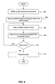
- processor 202 may determine a desired routing path between the pair of connection points (step 308). For example, processor 202 may determine a shortest path between the pair of connection points. Other types of desired paths, such as maximum space available, minimum direction changes, and/or most/least surface passage, etc., may also be used. Further, processor 202 may determine the desired routing path based on any appropriate algorithms. In certain embodiments, processor 202 may determine the desired routing path based on an ant colony algorithm. Fig. 4 shows an exemplary path finding process based on the ant colony algorithm.
- an ant colony algorithm may refer to an algorithm for finding desired or optimal paths based upon the behavior of ants searching for food.
- the behavior of ants searching for food may be described as follows: at the beginning of a search, the ants may wander randomly. However, when one ant finds a source of food, it walks back to its colony leaving markers (pheromones) to identify the path that leads to the food. When other ants come across the markers, a certain number of them may follow the path if they feel the path is a desired one. When the ants follow the path, they also leave the path with their own markers as they bring the food back.
- markers pheromones
- the ants leave pheromones every time they bring food, shorter paths are more likely to have higher level of pheromone or stronger pheromone. Further, some ants may be still randomly scouting for closer food sources. As more ants find the shorter path, the markers of the path become stronger and a majority of ants from the same colony use the shorter path. The shorter path may then be referred to as a desired or optimized path. At the same time, the pheromone may decay over time. If a path marked by pheromone is not traveled by the ants for a certain time, the pheromone level of the path will be weakened or even disappear.
- an ant may refer to a software agent (e.g., a self-contained software program capable of independent execution) that may be executed by processor 202 independently from other ants or software agents.
- a pheromone may refer to a weight having a value. Each ant may assign the weight when traveling a path.
- the weight (pheromone) value may be fixed or predetermined by processor 202.
- the weight value may also be variable over other parameters, such as time.
- an ant colony may refer to a particular pair of connection points (e.g., a path) or a group of paths that serve certain functionalities, such as electrical wiring, or hydraulic lines, etc.
- processor 202 may obtain 3D coordinates of a start point S and an end point T (step 402).
- Processor 202 may also set up a search space and 3D grids within the search space (step 404).
- the search space may be defined by a minimum coordinate (X min , Y min , Z min ) and a max coordinate (X max , Y max , Z max ).
- the entire space between the minimum coordinate and the maximum coordinate (at least including start point S and end point T) may be used as search space for finding a desired path between start point S and end point T.
- the 3D grids may refer to a pattern of X-axis (horizontal), ⁇ -axis (vertical), and Z-axis lines forming cubes of a uniform size.
- the 3D grids may be formed within the entire search space and each cube may be used as a smallest segment of a path. That is, the path between start point S and end point T includes a series of cubes located by their corresponding 3D coordinates (i.e., 3D grid points).
- Other 3D geometry shapes may also be used.
- the 3D grid approach may be referred to as an n-modal decomposition of a three-dimensional space.
- the three-dimensional space may also be described using a p-model decomposition, which may result in units of space that are not cubes. In some situations, such units may not be of regular geometry shapes.
- the uniform size of the 3D grids may be referred to as an increment in each axis of X-axis, Y-axis, and Z-axis for defining grid points.
- a path may be determined by connecting a series of adjacent grid points, and a grid point may also be used as a base point to measure physical dimension of the hose to be routed, such as a radius of the hose.
- the 3D grids may also include randomly generated 3D network of valid paths.
- processor 202 may start a certain number of ants (i.e., software agents) to search routing paths (step 406).
- ants i.e., software agents
- Each ant or software agent may determine a path between the start point S and the end point T by choosing certain grid points between S and T and mark the grid point with pheromone according to a probabilistic state transmission rule.
- the probabilistic state transmission rule may reflect the preference for an ant to choose a grid point with a high amount of pheromone (or a large weight) along a path.
- a certain number of ants may be able to complete traveling between the start point S and the end point T and a certain number of paths may then be created by different ants.
- a global updating may be performed to determine pheromone levels associated with the different paths.
- the global rule may be described as: ⁇ r ⁇ s ⁇ 1 - ⁇ .
- ⁇ ( r, s ) is the pheromone level
- 0 ⁇ ⁇ ⁇ 1 is a pheromone decay parameter
- L k is the length of the tour performed by ant k
- m is the number of ants that were able to complete their tour between the start point S and the end point T within the current turn or within certain number of turns
- ⁇ ⁇ ⁇ k r ⁇ s ⁇ 1 L k if r ⁇ s ⁇ tour done by ant k 0 , f r ⁇ s ⁇ tour done by ant k
- the total number of ants k may be set to 10
- initial pheromone level for each path may be set to 100
- the pheromone decay parameter ⁇ may be set to 0.01
- ⁇ may be set to 5.
- more than one ant colonies may be used for finding the path.
- the global update may also be performed when any ant completes traveling between the start point S and the end point T.
- the global update may also be performed periodically with a predetermined time interval. Further, the global update may be performed periodically and when an ant completes its tour between the start point S and the end point T. Once an ant completes its tour, the ant may be removed from the system because the ant no longer needs to travel (e.g., terminating the particular software agent).
- processor 202 may determine a shortest path with highest level of pheromone (step 408).
- processor 202 may determine whether a maximum number of turns or iterations have been reached (step 410). Processor 202 may obtain the maximum number of turns from database 214, from other application programs or computer systems, or from a user input. In one embodiment, the maximum number of turns may be set to about 10,000.
- processor 202 may continue the path finding process from step 406. On the other hand, if processor 202 determines that the maximum number of turns have been reached (step 410; no), processor 202 may present the shortest path to other applications programs or computer systems (step 412). Processor 202 may also present the shortest path and/or other associated information to a user through console 208.
- processor 202 may perform a physical check on the determined desired path (step 310).
- a physical check on the path may refer to a validity check of the path based upon the physical characteristics of the path (e.g., a physical hose or harness, etc.). For example, a hose may have a size requirement, and processor 202 may determine whether the hose of the particular size can fit in the space surrounding the shortest path based upon the solid model of the structural design. Other physical characteristics, such as configurations and contours, however, may also be used.
- processor 202 may determine whether the path is valid after the physical check (step 312). For example, processor 202 may determine whether a hose with a particular size fits in the space with or without considering other factors such as installation and/or maintenance. If processor 202 determines that the path is not valid (step 312; no), processor 202 may continue the determining process from step 308 to generate a different path. On the other hand, if processor 202 determines that the path is valid (step 312; yes), processor 202 may further determine whether additional parameters are to be considered (step 314).
- Additional parameters may include parameters that are not dimensional parameters of the hose or harness under physical check, but are related to the dimensional parameters in certain ways.
- an engine radiator pipe or hose may include a flow rate or a fluid pressure that is not a dimensional parameter but may have direct impact on choosing the dimensional parameters.
- a particular fluid pressure requirement may change the size of the pipe.
- a voltage loss requirement on an electrical wire may also cause dimensional parameter change in an electrical harness.
- processor 202 may determine an actual limitation on the physical or dimensional parameters and may further perform physical check again from step 310.
- processor 202 may present the results of the hose and harness routing process (step 316). If multiple pairs of connection points are selected, processor 202 may process each pair of the connection points as described above and may also present the results of multiple pairs of connection points. Processor 202 may present the results (e.g., locations, parameters of the hose or harness, etc.) to other applications programs or computer systems. Processor 202 may also present the results to a user through console 208 and/or other interfaces, such as a GUI. Further, a common pheromone distribution may also be presented.
- hoses or harnesses there may be several or many hoses or harnesses to be routed within the structural design. Routing of multiple hoses and harness is performed simultaneously using a multi-colony algorithm. Multiple paths between the same start point and end point as well as different paths between different connection points may need to be determined. In certain situations, hoses or paths may interfere or collide with each other because only one hose can occupy one space at any given time.
- the desired routing path may include certain turns in various degrees, or the routing path of a particular hose may need to be bend or turned to avoid interference or collision with the routing path of another hose.
- certain hoses, with physical characteristics, may be unable to bend or change directions according to the degree of a particular turn.
- Hose or pipe fittings may be used to change directions of the routing paths of hoses. Fittings may also be used to avoid a collision by changing the direction of a colliding path between two or more interfering paths.
- the space for such fittings may also need to be considered when determining whether a particular path is valid.
- processor 202 may perform a multi-path determining process to choose desired multiple paths.
- Fig. 5 shows an exemplary multi-path routing process consistent with the disclosed embodiments.
- Processor 202 may determine desired multiple paths based on a total cost of the paths.
- the cost of a path may refer to any appropriate and tangible measuring of either functional or physical characteristics of the path.
- the cost may include total length of multiple paths, length of shared paths, hose and harnesses cost, manufacturing cost, installation cost, maintenance cost, the amount of restraint on a particular functionality, the length of the path.
- the cost may also include physical weight of the hoses and harnesses, accessibility of the hoses and harnesses, and/or serviceability of the hoses and harnesses. Further, the cost may include any appropriate combinations of the above factors.
- processor 202 may select the desired multiple paths when the total cost of the paths is a minimum or is below a predetermined threshold.
- Various algorithms may be used by processor 202.
- processor 202 may determine the multiple paths based on a genetic algorithm and/or a multi-colony ant algorithm.
- processor 202 may set up and start a genetic algorithm (GA) (step 502).
- GA genetic algorithm
- the genetic algorithm may include any appropriate type of genetic algorithm that may be used to find possible optimized solutions based on the principles of adopting evolutionary biology to computer science.
- a particular order of the multiple paths may be associated with a variable and the multiple paths may be represented by a list of parameters used to drive an evaluation procedure of the genetic algorithm.
- the parameter list may be called a chromosome or a genome, which may represent an encoding of all variables, either selected or unselected. For example, a "0" encoding of a variable may indicate that the variable is not selected, while a "1" encoding of a variable may indicate that the variable is selected.
- Chromosomes may also include genes, each being an encoding of an individual variable. Chromosomes or genomes may be implemented as strings of data and/or instructions.
- a population may be a collection of a certain number of chromosomes.
- the chromosomes in the population may be evaluated based on a fitness function or a goal function, and a value of goodness or fitness may be returned by the fitness function or the goal function.
- the population may then be sorted, with those having better fitness ranked at the top.
- Processor 202 may set the fitness function or the goal function based on the total cost of the multiple paths.
- the genetic algorithm may generate a second population from the sorted initial population by using any or all of the genetic operators, such as selection, crossover (or reproduction), and mutation.
- selection chromosomes in the population with fitness values below a predetermined threshold may be deleted. Selection methods, such as roulette wheel selection and/or tournament selection, may also be used.
- reproduction operation may be performed upon the selected chromosomes. Two selected chromosomes may be crossed over along a randomly selected crossover point. Two new child chromosomes may then be created and added to the population. The reproduction operation may be continued until the population size is restored. Once the population size is restored, mutation may be selectively performed on the population. Mutation may be performed on a randomly selected chromosome by, for example, randomly altering bits in the chromosome data structure.
- Selection, reproduction, and mutation may result in a second generation population having chromosomes that are different from the initial generation.
- the average degree of fitness may be increased by this procedure for the second generation, since better fitted chromosomes from the first generation may be selected. This entire process may be repeated for any appropriate numbers of generations until the genetic algorithm converges.
- Processor 202 may determine a convergence based on the fitness function or goal function.
- processor 202 may select an order or priority among pairs of connection points or paths (step 504). Initially, processor 202 may generate a random order to start. And the order may be later selected based on GA operations, such as selection, crossover, or mutation, etc., as explained above. The order or priority may be referred to as a sequence in which an individual path (i.e., the ants of the individual path) starts. Further, processor 202 may determine shortest path for each path or connection (step 506). Processor 202 may use the process or processes described in Fig. 3 and/or Fig. 4 (the ant colony algorithm, etc.) to determine the shortest path for each pair of connection points. Other methods, however, may also be used.
- processor 202 may further determine whether there are conflicts among multiple paths (step 508). For example, different paths may collide with each other, certain paths may be unable to bend in arbitrary directions, or certain paths may need to be separated in a certain way, etc. If there is any conflict (step 508; yes), processor 202 may resolve the conflict (step 510).
- Processor 202 may resolve the conflict automatically based on predetermined algorithms or based on certain configurations. Processor 202 may also resolve the conflict based on user inputs. For example, processor 202 may present the conflict to a user or users of computer system 200, and the user may input rules and/or ways to resolve the conflict. In one embodiment, the user may combine more than one path together or keep several paths running parallel as much as possible. The user or processor 202 may also use pipe or hose fittings to change the direction of a particular path of a hose to cross a collision point between the particular path and a path of another hose. That is, processor 202 may use fittings to maneuver one hose around the other path such that the one path may pass the collision point without colliding with the other path.
- a small size hose may be bent or configured with fittings to cross over a large size hose at the collision point.
- priority of a hose e.g., based on the order of the paths, etc.
- a dominant path over which other paths need to traverse e.g., to cross over, etc.
- Other techniques may also be used.
- processor 202 may continue the process from step 506 to re-determine shortest paths with the constraints.
- processor 202 may calculate a total cost of the multiple paths (step 512). For example, as explained above, processor 202 may calculate a total manufacturing cost of the multiple paths. Other costs, however, may also be used.
- processor 202 may determine whether the GA converges (step 514). Processor 202 may determine the convergence based on the fitness function of the GA. In certain embodiments, the fitness function of the GA may indicate whether the total cost of the multiple paths is a desired value, such as a minimum total cost or a total cost below a predetermined threshold.
- processor 202 may continue the GA operations and the multi-path routing process from step 504. On the other hand, if processor 202 determines that the GA has converged (step 514; yes), processor 202 may complete the GA and present the results to other application programs or the user and complete the multi-path routing process (step 516).
- the order or priority among the multiple paths may be equal.
- the actual sequence may be randomly determined based on the operations of the GA and/or the algorithm for determining the shortest paths, such as the ant colony algorithm.
- the disclosed systems and methods may provide efficient and low cost solutions for hose and harness routing, which currently is performed by humans with support from expert systems such as structured design processes (SDPs) for electric lines or fluid lines.
- the fluid lines may include both flexible lines such as hoses and inflexible lines such as pipes.
- the disclosed systems and methods provide real-time re-routing after any late modifications made to structural components thus reducing or eliminating the manual or semi-manual process of finding spaces to fit the hoses and harnesses between the modified structural components.
- the disclosed systems and methods may be used in many industrial fields such as manufacturing, construction, designing, etc.
- a vehicle manufacturer may use the disclosed systems and methods to route electrical wirings and various pipes within the vehicle;
- a construction company may use the disclosed systems and methods to dispose pipes and wirings;
- a VLSI manufacturer may use the disclosed systems and methods to plan circuit layout;
- an aircraft manufacturer may use the disclosed systems for routing hoses and harnesses through wing sections;
- a shipbuilder may use the disclosed systems to route piping, hoses, and wiring through bulkheads, etc.
- the disclosed systems and methods may be used together with other computer aided design (CAD) or computer aided manufacturing (CAM) tools to provide automatic path re-routing after any modification made to the product design.
- CAD computer aided design
- CAM computer aided manufacturing
- the disclosed systems and methods may be provided in different ways.
- the disclosed systems and methods may be implemented as a computer system preloaded with software applications or may be provided as computer-readable media, etc.
Landscapes
- Engineering & Computer Science (AREA)
- Physics & Mathematics (AREA)
- Theoretical Computer Science (AREA)
- Geometry (AREA)
- General Physics & Mathematics (AREA)
- General Engineering & Computer Science (AREA)
- Computational Mathematics (AREA)
- Mathematical Analysis (AREA)
- Mathematical Optimization (AREA)
- Pure & Applied Mathematics (AREA)
- Computer Hardware Design (AREA)
- Evolutionary Computation (AREA)
- Aviation & Aerospace Engineering (AREA)
- Automation & Control Theory (AREA)
- Computer Networks & Wireless Communication (AREA)
- Data Mining & Analysis (AREA)
- Mathematical Physics (AREA)
- Algebra (AREA)
- Databases & Information Systems (AREA)
- Software Systems (AREA)
- Management, Administration, Business Operations System, And Electronic Commerce (AREA)
Abstract
Description
- This disclosure relates generally to computer based design techniques and, more particularly, to methods and systems for automatic hose and harness routing.
- Design of modem industrial products, such as vehicles, machines, equipment, architectures, consumer products, etc., often involve complex structural assemblies. Modem structural assemblies may be designed to be compact and cost efficient. In addition, the structural assemblies associated with hoses and/or harnesses often include wirings, cables, pipes, and other specific lines for purposes such as control, communication, fluid power or hydraulics, etc. Because a particular structure may only support a certain types of configuration of the hoses or harnesses, it may be desired to consider the routing of the hoses or harnesses during the design process of the structural assemblies such that the hoses may be aligned properly.
- However, even when the hose and harness routing is pre-considered, the designed structural assemblies may frequently undergo design changes for many reasons. Each time the structures are changed, the hose and harness routing often needs to be performed manually to adjust the changes in structure. Such manual performance may be time and/or cost consuming.
- Techniques for computer based routing calculation of the hoses and harnesses have been developed to reduce the amount of manual performance. For example, Sunand Sandurkar, Wei Chen, GAPRUS - genetic algorithms based pipe routing using tessellated objects, Computer in Industry 38, pp. 209-223 (1999), discloses a genetic algorithm based routing algorithm to globally search a routing path between two end points with minimum length and minimum number of bend. However, such a genetic algorithm often fails to consider various practical factors, such as priority between paths, real size of the path, etc., and/or to consider multiple routing paths of different connections simultaneously.
- Methods and systems consistent with certain features of the disclosed systems are directed to solving one or more of the problems set forth above.
- One aspect of the present disclosure includes a method for automatic hose and harness routing. The method may include obtaining a solid model of a structural design of a structure assembly and deriving a mathematical representation of the solid model. The method may also include selecting at least a pair of connection points including a start point and an end point and determining a desired path between the start point and the end point. Further, the method may include performing a validity check on the desired path to decide whether the desired path is valid and presenting the desired path.
- Another aspect of the present disclosure includes a method for automatic hose and harness routing. The method may include selecting a plurality of pairs of connection points and starting a genetic algorithm with a priority among the plurality of pairs of connection points. The method may also include determining a respective plurality of desired paths for the plurality of pairs of connection points in sequence according to the priority and calculating a total cost of the plurality of desired paths. Further, the method may include determining whether the total cost is below a predetermined threshold and completing the genetic algorithm if the total cost is below the predetermined threshold.
- Another aspect of the present disclosure includes a computer system. The computer system may include a processor and a database. The processor may be configured to obtain a solid model of a structural design of a structure assembly and to derive a mathematical representation of the solid model. The processor may also be configured to select at least a pair of connection points including a start point and an end point and determine a desired path between the start point and the end point. Further, the processor may be configured to perform a validity check on the desired path to decide whether the desired path is valid, and the database may be configured to store the desired path by the processor.
- Another aspect of the present disclosure includes a computer-readable medium for use on a computer system configured to perform automatic hose and harness routing, the computer-readable medium having computer-executable instructions for performing a method. The method may include obtaining a solid model of a structural design of a structure assembly and deriving a mathematical representation of the solid model. The method may also include selecting at least a pair of connection points including a start point and an end point and determining a desired path between the start point and the end point. Further, the method may include performing a validity check on the desired path to decide whether the desired path is valid and presenting the desired path.
-
- Fig. 1 is a pictorial illustration of an exemplary hose and harness routing process environment consistent with certain disclosed embodiments;
- Fig. 2 illustrates a block diagram of a computer system consistent with certain disclosed embodiments;
- Fig. 3 illustrates a flowchart of an exemplary hose and harness routing process consistent with certain disclosed embodiments;
- Fig. 4 shows an exemplary path finding process consistent with certain disclosed embodiments; and
- Fig. 5 shows a block diagram of an exemplary multi-path routing process consistent with certain disclosed embodiments.
- Reference will now be made in detail to exemplary embodiments, which are illustrated in the accompanying drawings. Wherever possible, the same reference numbers will be used throughout the drawings to refer to the same or like parts.
- Fig. 1 illustrates a block diagram of an exemplary automatic hose and
harness routing environment 100. As shown in Fig. 1, astructural design process 102 is coupled with arouting process 104.Structural design process 102 may also be coupled withother processes 106. -
Structural design process 102 may be provided to perform computer based design processes related to a particular structural assembly. A structural assembly may refer to any product or component of a product that includes one or more physical structures. For example, a structural assembly may include a vehicle, such as cars, trucks, construction vehicles, aircraft, etc., machines, factories, equipment, and/or consumer products, such as appliances, electronics, etc. Further, a structural assembly may also include a component of a product, such as a circuit board of an electronic product, or a load bearing assembly of a construction vehicle, etc. - A structural assembly may also include hoses and harnesses to be routed through the structural assembly or attached to certain surfaces of the structural assembly. As used in this specification, hoses and harnesses may refer to any appropriate type of physical lines of certain materials. For example, the hoses and harnesses may include wirings, cables, pipes, electrical harnesses, hydraulic lines, metal connections in printed circuit boards (PCB), etc.
-
Structural design process 102 may perform various structural design processes to generate a structural design of a particular structure assembly. The structural design may be represented in any appropriate computer recognizable data form, such as forms used by a CAD software program. The structural design may also be provided toother processes 106 to improve the structural design or to use the structural design for other purposes, such as integrating the structural design into a complete product or into other products, etc.Other processes 106 may include one or more processes for performing any appropriate type of design functionality together withstructural design process 102. -
Other processes 106 may modify the structural design created bystructural design process 102 and may provide the modifications back tostructural design process 102.Other processes 106 may also send required modifications tostructural design process 102 without making actual modification. Andstructural design process 102, after receiving modification requirements fromother processes 106, may change the structural design accordingly. Therefore, a new version of the structural design may be generated. Such interactions betweenstructural design process 102 andother process 106 may continue until the structural design is finalized. - When
structural design process 102 generates a structural design,structural design process 102 may provide the structural design torouting process 104 for automatically performing hose and harness routing for the structural design.Routing process 104 may perform hose and harness routing based on the structural design and other appropriate type of information, such as geometric constraints of the structural design, physical size requirement for the hoses or harnesses, and/or schematic information containing information on starting points, ending points, and/or passing points of various hoses and harnesses as well as performance requirements associated with the schematic, such as current drop, voltage drop, pressure losses, and/or flow rates, etc. -
Routing process 104,structural design process 102, and/orother processes 106 may be carried out by one or more computer systems. Fig. 2 shows a functional block diagram of anexemplary computer system 200 that may be used to perform these processes. - As shown in Fig. 2,
computer system 200 may include aprocessor 202, a random access memory (RAM) 204, a read-only memory (ROM) 206, aconsole 208, aninput device 210, anetwork interface 212, adatabases 214, and astorage 216. It is understood that the type and number of listed devices are exemplary only and not intended to be limiting. The number of listed devices may be changed and other devices may be added. -
Processor 202 may include any appropriate type of general purpose microprocessor, digital signal processor, or microcontroller.Processor 202 may execute sequences of computer program instructions to perform various processes as explained above. The computer program instructions may be loaded intoRAM 204 for execution byprocessor 202 from a read-only memory (ROM), or fromstorage 216.Storage 216 may include any appropriate type of mass storage provided to store any type of information thatprocessor 202 may need to perform the processes, such as the computer program instructions and/or various data. For example,storage 216 may include one or more hard disk device, floppy disk, optical disk device, or other storage device to provide storage space. -
Console 208 may provide a graphic user interface (GUI) to display or present information to users ofcomputer system 200.Console 208 may include any appropriate type of computer display device or computer monitor.Input device 210 may be provided for users to input information intocomputer system 200.Input device 210 may include a keyboard, a mouse, or other optical or wireless computer input devices, etc. Further,network interface 212 may provide communication connections such thatcomputer system 200 may be accessed remotely through computer networks via various communication protocols, such as transmission control protocol/internet protocol (TCP/IP), hyper text transfer protocol (HTTP), etc. -
Database 214 may contain model data and/or any information related to the processes, such as configuration data, algorithm data, structural parameters, and/or any other design data, etc.Database 214 may include any type of commercial or customized database.Database 214 may also include analysis tools for analyzing the information in the database.Processor 202 may usedatabase 214 to determine and store performance characteristics of the processes. - In certain embodiments,
processor 202 may performrouting process 104 to automatically find routing paths for a structural design generated bystructural design process 102. Fig. 3 shows a flowchart diagram of an exemplary automatic hose and harness routing process performed byprocessor 202. - As shown in Fig. 3, at the beginning of the hose and harness routing process,
processor 202 may obtain a solid model of a structural design (step 302). A solid model may refer to any structural design model that reflects physical characteristics of structures included in the model and space relationships among the structures.Processor 202 may obtain the solid model fromstructural design process 102.Processor 202 may also obtain the solid model from any appropriate design applications running oncomputer system 200 and/or from other computer systems or design applications. Afterprocessor 202 obtains the solid model,processor 202 may derive a mathematic representation or representations of the solid model (step 304).Processor 202 may use any appropriate mathematic format to represent the solid model. In certain embodiments,processor 202 may use a stereo lithography (STL) tessellated format to represent the solid model. - The STL format defines surfaces of a solid object as a set of adjacent triangles. The tessellated format defines that each edge is shared only by two triangles. Under the STL tessellated format, the solid object may be represented by X, Y, Z Cartesian coordinates of each vertex of the triangles and coordinates of normal vectors to the triangles, with each edge being shared by two triangles. These 3D coordinates may be included in an ASCII or binary file to be used by various software application programs. The accuracy of the STL tessellated format may depend on the number of triangles representing a solid model. A larger number of triangles may provide a higher accuracy.
-
Processor 202 may select connection points through which the hoses and harnesses are to be routed (step 306). In certain embodiments,processor 202 may select connection points in pairs. For example,processor 202 may select a pair of connection points to be routed. Hose and harness routing may be realized by selecting a desired path between the pair of connection points. The pair of connection points may include a start point and an end point. The hoses and harnesses may be provided between the start point and the end point based on the STL format representation of the solid model. Further, multiple pairs of connection points may routed in a same way separately. - In certain other embodiments, the connection points may not be in pairs. For example, hoses and harnesses may be so-called "flying splices" such that the connection points include a start point and multiple end points, and vice versa.
Processor 202 may treat the flying splices as multiple pairs of connection points or may use a middle connection point or points such that pairs of connection points may be used. - Each connection point (e.g., the start point or the end point) may be represented by corresponding 3D coordinates on X, Y, and Z axes. Further,
processor 202 may select the connection points based on the structural model or based on inputs from a user or users ofcomputer system 200. For example, the user may input or select connection point from a GUI onconsole 208 throughinput devices 210. - After
processor 202 selects the pair of connection points (step 306),processor 202 may determine a desired routing path between the pair of connection points (step 308). For example,processor 202 may determine a shortest path between the pair of connection points. Other types of desired paths, such as maximum space available, minimum direction changes, and/or most/least surface passage, etc., may also be used. Further,processor 202 may determine the desired routing path based on any appropriate algorithms. In certain embodiments,processor 202 may determine the desired routing path based on an ant colony algorithm. Fig. 4 shows an exemplary path finding process based on the ant colony algorithm. - As used herein, an ant colony algorithm may refer to an algorithm for finding desired or optimal paths based upon the behavior of ants searching for food. The behavior of ants searching for food may be described as follows: at the beginning of a search, the ants may wander randomly. However, when one ant finds a source of food, it walks back to its colony leaving markers (pheromones) to identify the path that leads to the food. When other ants come across the markers, a certain number of them may follow the path if they feel the path is a desired one. When the ants follow the path, they also leave the path with their own markers as they bring the food back.
- Because the ants leave pheromones every time they bring food, shorter paths are more likely to have higher level of pheromone or stronger pheromone. Further, some ants may be still randomly scouting for closer food sources. As more ants find the shorter path, the markers of the path become stronger and a majority of ants from the same colony use the shorter path. The shorter path may then be referred to as a desired or optimized path. At the same time, the pheromone may decay over time. If a path marked by pheromone is not traveled by the ants for a certain time, the pheromone level of the path will be weakened or even disappear.
- When using the ant colony algorithm to find an optimal path, an ant may refer to a software agent (e.g., a self-contained software program capable of independent execution) that may be executed by
processor 202 independently from other ants or software agents. A pheromone may refer to a weight having a value. Each ant may assign the weight when traveling a path. The weight (pheromone) value may be fixed or predetermined byprocessor 202. The weight value may also be variable over other parameters, such as time. Further, an ant colony may refer to a particular pair of connection points (e.g., a path) or a group of paths that serve certain functionalities, such as electrical wiring, or hydraulic lines, etc. - As shown in Fig. 4, at the beginning of the path finding process,
processor 202 may obtain 3D coordinates of a start point S and an end point T (step 402).Processor 202 may also set up a search space and 3D grids within the search space (step 404). The search space may be defined by a minimum coordinate (Xmin, Ymin, Zmin) and a max coordinate (Xmax, Ymax, Zmax). The entire space between the minimum coordinate and the maximum coordinate (at least including start point S and end point T) may be used as search space for finding a desired path between start point S and end point T. - The 3D grids may refer to a pattern of X-axis (horizontal), γ-axis (vertical), and Z-axis lines forming cubes of a uniform size. The 3D grids may be formed within the entire search space and each cube may be used as a smallest segment of a path. That is, the path between start point S and end point T includes a series of cubes located by their corresponding 3D coordinates (i.e., 3D grid points). Other 3D geometry shapes, however, may also be used. For example, when using finite element analysis (FEA), the 3D grid approach may be referred to as an n-modal decomposition of a three-dimensional space. However, the three-dimensional space may also be described using a p-model decomposition, which may result in units of space that are not cubes. In some situations, such units may not be of regular geometry shapes.
- Further, the uniform size of the 3D grids may be referred to as an increment in each axis of X-axis, Y-axis, and Z-axis for defining grid points. A path may be determined by connecting a series of adjacent grid points, and a grid point may also be used as a base point to measure physical dimension of the hose to be routed, such as a radius of the hose. In certain embodiments, the 3D grids may also include randomly generated 3D network of valid paths.
- After
processor 202 sets up the 3D grids and selects the search space (step 404),processor 202 may start a certain number of ants (i.e., software agents) to search routing paths (step 406). Each ant or software agent may determine a path between the start point S and the end point T by choosing certain grid points between S and T and mark the grid point with pheromone according to a probabilistic state transmission rule. The probabilistic state transmission rule may reflect the preference for an ant to choose a grid point with a high amount of pheromone (or a large weight) along a path. The probabilistic state transmission rule may be described to as:
- After a certain amount of time, which may be referred to as a turn or an iteration, a certain number of ants may be able to complete traveling between the start point S and the end point T and a certain number of paths may then be created by different ants. A global updating may be performed to determine pheromone levels associated with the different paths. The global rule may be described as:


- Further, in certain embodiments, more than one ant colonies may be used for finding the path. The global rule may then be described as:

where τ(r, s) is the pheromone level, and

where Lck is length of path Pck and sck is total shared length of path Pck with paths produced by ants of other colonies (i.e. other than colony c). Total shared length sck may be defined as
where l is length and mc' is number of ants in colony c' that were able to complete their tours within the stipulated turns Nturns. w1 and w2 (w1 + w2 = 1) are two weights that measure importance of the length of path Pck relative to total shared length sck. - The global update may also be performed when any ant completes traveling between the start point S and the end point T. The global update may also be performed periodically with a predetermined time interval. Further, the global update may be performed periodically and when an ant completes its tour between the start point S and the end point T. Once an ant completes its tour, the ant may be removed from the system because the ant no longer needs to travel (e.g., terminating the particular software agent). After each global update,
processor 202 may determine a shortest path with highest level of pheromone (step 408). - Further,
processor 202 may determine whether a maximum number of turns or iterations have been reached (step 410).Processor 202 may obtain the maximum number of turns fromdatabase 214, from other application programs or computer systems, or from a user input. In one embodiment, the maximum number of turns may be set to about 10,000. - If
processor 202 determines that the maximum number of turns or iterations have not been reached (step 410; yes),processor 202 may continue the path finding process fromstep 406. On the other hand, ifprocessor 202 determines that the maximum number of turns have been reached (step 410; no),processor 202 may present the shortest path to other applications programs or computer systems (step 412).Processor 202 may also present the shortest path and/or other associated information to a user throughconsole 208. - Returning to Fig. 3, after determining the desired routing path (step 308),
processor 202 may perform a physical check on the determined desired path (step 310). A physical check on the path may refer to a validity check of the path based upon the physical characteristics of the path (e.g., a physical hose or harness, etc.). For example, a hose may have a size requirement, andprocessor 202 may determine whether the hose of the particular size can fit in the space surrounding the shortest path based upon the solid model of the structural design. Other physical characteristics, such as configurations and contours, however, may also be used. - Further,
processor 202 may determine whether the path is valid after the physical check (step 312). For example,processor 202 may determine whether a hose with a particular size fits in the space with or without considering other factors such as installation and/or maintenance. Ifprocessor 202 determines that the path is not valid (step 312; no),processor 202 may continue the determining process fromstep 308 to generate a different path. On the other hand, ifprocessor 202 determines that the path is valid (step 312; yes),processor 202 may further determine whether additional parameters are to be considered (step 314). - Additional parameters may include parameters that are not dimensional parameters of the hose or harness under physical check, but are related to the dimensional parameters in certain ways. For example, an engine radiator pipe or hose may include a flow rate or a fluid pressure that is not a dimensional parameter but may have direct impact on choosing the dimensional parameters. A particular fluid pressure requirement may change the size of the pipe. For another example, a voltage loss requirement on an electrical wire may also cause dimensional parameter change in an electrical harness.
- If
processor 202 determines that additional parameters need to be considered (step 314; yes),processor 202 may determine an actual limitation on the physical or dimensional parameters and may further perform physical check again fromstep 310. - On the other hand, if
processor 202 determines that no additional parameters need to be considered (step 314; no),processor 202 may present the results of the hose and harness routing process (step 316). If multiple pairs of connection points are selected,processor 202 may process each pair of the connection points as described above and may also present the results of multiple pairs of connection points.Processor 202 may present the results (e.g., locations, parameters of the hose or harness, etc.) to other applications programs or computer systems.Processor 202 may also present the results to a user throughconsole 208 and/or other interfaces, such as a GUI. Further, a common pheromone distribution may also be presented. - In certain practical applications, there may be several or many hoses or harnesses to be routed within the structural design. Routing of multiple hoses and harness is performed simultaneously using a multi-colony algorithm. Multiple paths between the same start point and end point as well as different paths between different connection points may need to be determined. In certain situations, hoses or paths may interfere or collide with each other because only one hose can occupy one space at any given time.
- In other situations, the desired routing path may include certain turns in various degrees, or the routing path of a particular hose may need to be bend or turned to avoid interference or collision with the routing path of another hose. However, certain hoses, with physical characteristics, may be unable to bend or change directions according to the degree of a particular turn. Hose or pipe fittings may be used to change directions of the routing paths of hoses. Fittings may also be used to avoid a collision by changing the direction of a colliding path between two or more interfering paths. In addition, the space for such fittings may also need to be considered when determining whether a particular path is valid.
- To solve this multiple hosing problem,
processor 202 may perform a multi-path determining process to choose desired multiple paths. Fig. 5 shows an exemplary multi-path routing process consistent with the disclosed embodiments. -
Processor 202 may determine desired multiple paths based on a total cost of the paths. As used herein, the cost of a path may refer to any appropriate and tangible measuring of either functional or physical characteristics of the path. For example, the cost may include total length of multiple paths, length of shared paths, hose and harnesses cost, manufacturing cost, installation cost, maintenance cost, the amount of restraint on a particular functionality, the length of the path. The cost may also include physical weight of the hoses and harnesses, accessibility of the hoses and harnesses, and/or serviceability of the hoses and harnesses. Further, the cost may include any appropriate combinations of the above factors. In certain embodiments,processor 202 may select the desired multiple paths when the total cost of the paths is a minimum or is below a predetermined threshold. Various algorithms may be used byprocessor 202. - As shown in Fig. 5,
processor 202 may determine the multiple paths based on a genetic algorithm and/or a multi-colony ant algorithm. At the beginning of the process,processor 202 may set up and start a genetic algorithm (GA) (step 502). The genetic algorithm may include any appropriate type of genetic algorithm that may be used to find possible optimized solutions based on the principles of adopting evolutionary biology to computer science. - When applying a genetic algorithm to search a desired combination of multiple routing paths, a particular order of the multiple paths may be associated with a variable and the multiple paths may be represented by a list of parameters used to drive an evaluation procedure of the genetic algorithm. The parameter list may be called a chromosome or a genome, which may represent an encoding of all variables, either selected or unselected. For example, a "0" encoding of a variable may indicate that the variable is not selected, while a "1" encoding of a variable may indicate that the variable is selected. Chromosomes may also include genes, each being an encoding of an individual variable. Chromosomes or genomes may be implemented as strings of data and/or instructions.
- Initially, several such parameter lists or chromosomes may be generated to create a population. A population may be a collection of a certain number of chromosomes. The chromosomes in the population may be evaluated based on a fitness function or a goal function, and a value of goodness or fitness may be returned by the fitness function or the goal function. The population may then be sorted, with those having better fitness ranked at the top.
Processor 202 may set the fitness function or the goal function based on the total cost of the multiple paths. - The genetic algorithm may generate a second population from the sorted initial population by using any or all of the genetic operators, such as selection, crossover (or reproduction), and mutation. During selection, chromosomes in the population with fitness values below a predetermined threshold may be deleted. Selection methods, such as roulette wheel selection and/or tournament selection, may also be used. After selection, reproduction operation may be performed upon the selected chromosomes. Two selected chromosomes may be crossed over along a randomly selected crossover point. Two new child chromosomes may then be created and added to the population. The reproduction operation may be continued until the population size is restored. Once the population size is restored, mutation may be selectively performed on the population. Mutation may be performed on a randomly selected chromosome by, for example, randomly altering bits in the chromosome data structure.
- Selection, reproduction, and mutation may result in a second generation population having chromosomes that are different from the initial generation. The average degree of fitness may be increased by this procedure for the second generation, since better fitted chromosomes from the first generation may be selected. This entire process may be repeated for any appropriate numbers of generations until the genetic algorithm converges.
Processor 202 may determine a convergence based on the fitness function or goal function. - After
processor 202 sets up and starts the GA (step 502),processor 202 may select an order or priority among pairs of connection points or paths (step 504). Initially,processor 202 may generate a random order to start. And the order may be later selected based on GA operations, such as selection, crossover, or mutation, etc., as explained above. The order or priority may be referred to as a sequence in which an individual path (i.e., the ants of the individual path) starts. Further,processor 202 may determine shortest path for each path or connection (step 506).Processor 202 may use the process or processes described in Fig. 3 and/or Fig. 4 (the ant colony algorithm, etc.) to determine the shortest path for each pair of connection points. Other methods, however, may also be used. - After respective shortest paths are determined,
processor 202 may further determine whether there are conflicts among multiple paths (step 508). For example, different paths may collide with each other, certain paths may be unable to bend in arbitrary directions, or certain paths may need to be separated in a certain way, etc. If there is any conflict (step 508; yes),processor 202 may resolve the conflict (step 510). -
Processor 202 may resolve the conflict automatically based on predetermined algorithms or based on certain configurations.Processor 202 may also resolve the conflict based on user inputs. For example,processor 202 may present the conflict to a user or users ofcomputer system 200, and the user may input rules and/or ways to resolve the conflict. In one embodiment, the user may combine more than one path together or keep several paths running parallel as much as possible. The user orprocessor 202 may also use pipe or hose fittings to change the direction of a particular path of a hose to cross a collision point between the particular path and a path of another hose. That is,processor 202 may use fittings to maneuver one hose around the other path such that the one path may pass the collision point without colliding with the other path. For example, a small size hose may be bent or configured with fittings to cross over a large size hose at the collision point. In certain embodiments, priority of a hose (e.g., based on the order of the paths, etc.) may also be used to determine a dominant path over which other paths need to traverse (e.g., to cross over, etc.). Other techniques, however, may also be used. Once selected, the conflict resolving mechanism may remain until further changed byprocessor 202. - After resolving the conflict (step 510),
processor 202 may continue the process fromstep 506 to re-determine shortest paths with the constraints. On the other hand, ifprocessor 202 determines that there is no conflict between the multiple paths (step 508; no),processor 202 may calculate a total cost of the multiple paths (step 512). For example, as explained above,processor 202 may calculate a total manufacturing cost of the multiple paths. Other costs, however, may also be used. - Further,
processor 202 may determine whether the GA converges (step 514).Processor 202 may determine the convergence based on the fitness function of the GA. In certain embodiments, the fitness function of the GA may indicate whether the total cost of the multiple paths is a desired value, such as a minimum total cost or a total cost below a predetermined threshold. - If
processor 202 determines that the GA has not converged (step 514; no),processor 202 may continue the GA operations and the multi-path routing process fromstep 504. On the other hand, ifprocessor 202 determines that the GA has converged (step 514; yes),processor 202 may complete the GA and present the results to other application programs or the user and complete the multi-path routing process (step 516). - In other embodiments, the order or priority among the multiple paths may be equal. The actual sequence may be randomly determined based on the operations of the GA and/or the algorithm for determining the shortest paths, such as the ant colony algorithm.
- The disclosed systems and methods may provide efficient and low cost solutions for hose and harness routing, which currently is performed by humans with support from expert systems such as structured design processes (SDPs) for electric lines or fluid lines. The fluid lines may include both flexible lines such as hoses and inflexible lines such as pipes. The disclosed systems and methods provide real-time re-routing after any late modifications made to structural components thus reducing or eliminating the manual or semi-manual process of finding spaces to fit the hoses and harnesses between the modified structural components.
- The disclosed systems and methods may be used in many industrial fields such as manufacturing, construction, designing, etc. For example, a vehicle manufacturer may use the disclosed systems and methods to route electrical wirings and various pipes within the vehicle; a construction company may use the disclosed systems and methods to dispose pipes and wirings; a VLSI manufacturer may use the disclosed systems and methods to plan circuit layout; an aircraft manufacturer may use the disclosed systems for routing hoses and harnesses through wing sections; a shipbuilder may use the disclosed systems to route piping, hoses, and wiring through bulkheads, etc.
- Further, the disclosed systems and methods may be used together with other computer aided design (CAD) or computer aided manufacturing (CAM) tools to provide automatic path re-routing after any modification made to the product design. The disclosed systems and methods may be provided in different ways. For example, the disclosed systems and methods may be implemented as a computer system preloaded with software applications or may be provided as computer-readable media, etc.
- Other embodiments, features, aspects, and principles of the disclosed exemplary systems will be apparent to those skilled in the art and may be implemented in various environments and systems.
Claims (10)
- A method for automatic hose and harness routing, comprising:obtaining a solid model of a structural design of a structure assembly;deriving a mathematical representation of the solid model;selecting at least a pair of connection points including a start point and an end point;determining a desired path between the start point and the end point;performing a validity check on the desired path to decide whether the desired path is valid; andpresenting the desired path.
- The method according to claim 1, further including:determining, if the desired path is not valid, a second desired path between the start point and the end point.
- The method according to claim 1, further including:adding additional restraints to the desired path; andre-performing the validity check on the desired path with the additional restraints.
- The method according to claim 1, wherein the mathematic representation is a stereo lithography (STL) tessellated format representation of the solid model.
- The method according to claim 1, wherein the determining includes:setting up a search space enclosing the start point and the end point;forming 3D grids within the search space;starting a predetermined number of ants to travel through the 3D grids based on a first rule such that a plurality of paths between the start point and the end point are created, each path is determined by a plurality of 3D grid points connecting the start point and the end point are marked with pheromones by one or more ants from the predetermined number of ants;updating respective pheromone levels of the plurality of paths based on a second rule; anddetermining the desired path as one with a highest level of pheromone among the plurality of paths.
- The method according to claim 5, wherein, provided that k is an integer, τ is the pheromone, r and s are two points represented by 3D coordinates, η =1/δ is the inverse of the distance from the point s to a target point [δ(r,s)], Jk(r) is the set of neighboring points of r that remain to be visited by ant k positioned on the point r, and β is a parameter which determines the relative importance of pheromone versus distance (β > 0), the first rule is represented by:

- The method according to claim 6, wherein pheromone level τ(r, s) is based on at least a pheromone decay parameter and pheromone contributions from ants being able to complete their tour between the start point and the end point.
- The method according to claim 1, wherein the performing the validity check includes:assigning dimensional parameters to the desired path; anddetermining whether the desired path with the dimensional parameters fits in space surrounding the desired path based on the solid model.
- A computer system (200), comprising:a processor (202) configured to:obtain a solid model of a structural design of a structure assembly;derive a mathematical representation of the solid model;select at least a pair of connection points including a start point and an end point;determine a desired path between the start point and the end point; andperform a validity check on the desired path to decide whether the desired path is valid, anda database (214) for storing the desired path by the processor.
- The computer system according to claim 9, wherein, to perform the validity check, the processor is further configured to:assign dimensional parameters to the desired path; anddetermine whether the desired path with the dimensional parameters fits in space surrounding the desired path based on the solid model.
Applications Claiming Priority (2)
| Application Number | Priority Date | Filing Date | Title |
|---|---|---|---|
| US79558806P | 2006-04-28 | 2006-04-28 | |
| US11/790,183 US7792662B2 (en) | 2006-04-28 | 2007-04-24 | Automatic hose and harness routing method and system |
Publications (1)
| Publication Number | Publication Date |
|---|---|
| EP1850252A1 true EP1850252A1 (en) | 2007-10-31 |
Family
ID=38283522
Family Applications (1)
| Application Number | Title | Priority Date | Filing Date |
|---|---|---|---|
| EP07008607A Withdrawn EP1850252A1 (en) | 2006-04-28 | 2007-04-27 | Automatic hose and harness routing method and system |
Country Status (2)
| Country | Link |
|---|---|
| US (1) | US7792662B2 (en) |
| EP (1) | EP1850252A1 (en) |
Cited By (3)
| Publication number | Priority date | Publication date | Assignee | Title |
|---|---|---|---|---|
| EP2477131A1 (en) * | 2011-01-14 | 2012-07-18 | BAE Systems PLC | Assisting with installation of conduits |
| CN103778277A (en) * | 2013-12-31 | 2014-05-07 | 浙江浙大中控信息技术有限公司 | Connecting line drawing optimizing method of sewage treatment simulation software |
| GB2589882A (en) * | 2019-12-10 | 2021-06-16 | Airbus Sas | Method of identifying routes for a harness or hose |
Families Citing this family (12)
| Publication number | Priority date | Publication date | Assignee | Title |
|---|---|---|---|---|
| WO2008084534A1 (en) * | 2007-01-10 | 2008-07-17 | Fujitsu Limited | Design support system, method and program |
| US8706452B2 (en) * | 2008-06-26 | 2014-04-22 | Siemens Product Lifecycle Management Software Inc. | System and method for collision-free CAD design of pipe and tube paths |
| JP5195641B2 (en) * | 2009-05-26 | 2013-05-08 | 富士通株式会社 | Harness verification device and harness verification program |
| KR101642540B1 (en) * | 2012-11-27 | 2016-07-25 | 엘지전자 주식회사 | An installation guide system for an air conditioner and a using method the same |
| KR20140067750A (en) | 2012-11-27 | 2014-06-05 | 엘지전자 주식회사 | An installation guide system for an air conditioner and a using method the same |
| KR101642541B1 (en) | 2012-11-27 | 2016-07-25 | 엘지전자 주식회사 | An installation guide system for an air conditioner and a using method the same |
| US10027051B1 (en) * | 2017-02-20 | 2018-07-17 | Robert Bosch Gmbh | Hybrid electrical connector |
| CN109740789B (en) * | 2018-11-22 | 2023-07-25 | 平安科技(深圳)有限公司 | Wiring management method, device, equipment and storage medium |
| CN109583667B (en) * | 2019-01-08 | 2023-04-18 | 北京航空航天大学 | Cable path solving and optimizing method |
| CN110688706B (en) * | 2019-08-30 | 2022-10-28 | 北京卫星制造厂有限公司 | Design method, system and medium of spacecraft hose |
| CN111523179B (en) * | 2020-05-06 | 2022-09-06 | 一汽解放汽车有限公司 | Pipe bundle checking method, device, equipment and storage medium |
| CN113823394B (en) * | 2021-11-22 | 2022-04-05 | 宏景科技股份有限公司 | Intelligent diagnosis guiding method, system, equipment and medium based on ant colony algorithm |
Family Cites Families (2)
| Publication number | Priority date | Publication date | Assignee | Title |
|---|---|---|---|---|
| CA2052983C (en) * | 1991-09-16 | 2002-05-21 | David H. Devonald, Iii | Interconnection arrangement for electrical equipment enclosures |
| US6981316B2 (en) * | 1994-08-08 | 2006-01-03 | Cooper Technologies Company | Method of manufacturing vehicle electric power distribution system |
-
2007
- 2007-04-24 US US11/790,183 patent/US7792662B2/en not_active Expired - Fee Related
- 2007-04-27 EP EP07008607A patent/EP1850252A1/en not_active Withdrawn
Non-Patent Citations (4)
| Title |
|---|
| "Ant colony optimization", 22 April 2006 (2006-04-22), XP002444862, Retrieved from the Internet <URL:http://en.wikipedia.org/w/index.php?title=Ant_colony_optimization&oldid=49603872&printable=yes> [retrieved on 20070730] * |
| CONRU A B: "A genetic approach to the cable harness routing problem", EVOLUTIONARY COMPUTATION, 1994. IEEE WORLD CONGRESS ON COMPUTATIONAL INTELLIGENCE., PROCEEDINGS OF THE FIRST IEEE CONFERENCE ON ORLANDO, FL, USA 27-29 JUNE 1994, NEW YORK, NY, USA,IEEE, 27 June 1994 (1994-06-27), pages 200 - 205, XP010122848, ISBN: 0-7803-1899-4 * |
| KUAN ET AL: "Solving the feeder bus network design problem by genetic algorithms and ant colony optimization", ADVANCES IN ENGINEERING SOFTWARE, ELSEVIER SCIENCE, OXFORD, GB, vol. 37, no. 6, June 2006 (2006-06-01), pages 351 - 359, XP005512059, ISSN: 0965-9978 * |
| SANDURKAR SUNAND ET AL: "GAPRUS - genetic algorithms based pipe routing using tessellated objects", COMPUTERS IN INDUSTRY, ELSEVIER SCIENCE PUBLISHERS. AMSTERDAM, NL, vol. 38, no. 3, April 1999 (1999-04-01), pages 209 - 223, XP002252558, ISSN: 0166-3615 * |
Cited By (4)
| Publication number | Priority date | Publication date | Assignee | Title |
|---|---|---|---|---|
| EP2477131A1 (en) * | 2011-01-14 | 2012-07-18 | BAE Systems PLC | Assisting with installation of conduits |
| CN103778277A (en) * | 2013-12-31 | 2014-05-07 | 浙江浙大中控信息技术有限公司 | Connecting line drawing optimizing method of sewage treatment simulation software |
| CN103778277B (en) * | 2013-12-31 | 2017-01-11 | 浙江浙大中控信息技术有限公司 | Connecting line drawing optimizing method of sewage treatment simulation software |
| GB2589882A (en) * | 2019-12-10 | 2021-06-16 | Airbus Sas | Method of identifying routes for a harness or hose |
Also Published As
| Publication number | Publication date |
|---|---|
| US7792662B2 (en) | 2010-09-07 |
| US20080015824A1 (en) | 2008-01-17 |
Similar Documents
| Publication | Publication Date | Title |
|---|---|---|
| US7792662B2 (en) | Automatic hose and harness routing method and system | |
| JP5269196B2 (en) | System and method for CAD design of collision free piping paths | |
| CN110866332B (en) | Complex cable assembly assembling method and system | |
| JP2010009595A (en) | Sampling strategy using genetic algorithm (ga) for optimizing engineering design | |
| CN110967028A (en) | Navigation map construction method and device, robot and storage medium | |
| EP2998078A1 (en) | Method for improving efficiency of industrial robotic energy consumption and cycle time by handling orientation at task location | |
| Masuda et al. | Rule‐based searching for collision test cases of autonomous vehicles simulation | |
| Guimaraes Macharet et al. | An evolutionary approach for the Dubins' traveling salesman problem with neighborhoods | |
| WO2015131025A1 (en) | Method and apparatus for rapid approximation of system model | |
| Kim et al. | Application of reinforcement learning based on curriculum learning for the pipe auto-routing of ships | |
| Parvez et al. | Path planning optimization using genetic algorithm | |
| EP4185962A1 (en) | Validating a software-driven system based on real-world scenarios | |
| Du et al. | Scheduling of stochastic distributed assembly flowshop under complex constraints | |
| JPH1039909A (en) | Work scheduling method for plural robots | |
| Cuellar‐Usaquén et al. | Modeling and solving the endpoint cutting problem | |
| Cho et al. | Inference on robotic assembly precedence constraints using a part contact level graph | |
| Weise et al. | Graph-based multi-objective generation of customised wiring harnesses | |
| CN114743385B (en) | Vehicle processing method and device and computer equipment | |
| Hermansson et al. | Routing of curves with piecewise constant curvature applied to routing of preformed hoses | |
| Hliwa et al. | Multi objective path planning in static environment using region of sight | |
| Karlsson et al. | Automatic cable harness layout routing in a customizable 3D environment | |
| CN113987665B (en) | Optimization method and device for removing pipeline collision of building equipment system | |
| US11872703B2 (en) | Method and device for deterministic sampling-based motion planning | |
| Utami et al. | Path planning for differential drive mobile robot to avoid static obstacles collision using modified crossover genetic algorithm | |
| JPH1021269A (en) | Method and device for supporting design of wiring route |
Legal Events
| Date | Code | Title | Description |
|---|---|---|---|
| PUAI | Public reference made under article 153(3) epc to a published international application that has entered the european phase |
Free format text: ORIGINAL CODE: 0009012 |
|
| AK | Designated contracting states |
Kind code of ref document: A1 Designated state(s): AT BE BG CH CY CZ DE DK EE ES FI FR GB GR HU IE IS IT LI LT LU LV MC MT NL PL PT RO SE SI SK TR |
|
| AX | Request for extension of the european patent |
Extension state: AL BA HR MK YU |
|
| 17P | Request for examination filed |
Effective date: 20080402 |
|
| 17Q | First examination report despatched |
Effective date: 20080513 |
|
| AKX | Designation fees paid |
Designated state(s): AT BE BG CH CY CZ DE DK EE ES FI FR GB GR HU IE IS IT LI LT LU LV MC MT NL PL PT RO SE SI SK TR |
|
| STAA | Information on the status of an ep patent application or granted ep patent |
Free format text: STATUS: THE APPLICATION IS DEEMED TO BE WITHDRAWN |
|
| 18D | Application deemed to be withdrawn |
Effective date: 20090421 |