EP1848976B1 - Method and device for detecting, on the ground, the obstruction of a pressure tap of a static pressure sensor of an aircraft - Google Patents
Method and device for detecting, on the ground, the obstruction of a pressure tap of a static pressure sensor of an aircraft Download PDFInfo
- Publication number
- EP1848976B1 EP1848976B1 EP06709220A EP06709220A EP1848976B1 EP 1848976 B1 EP1848976 B1 EP 1848976B1 EP 06709220 A EP06709220 A EP 06709220A EP 06709220 A EP06709220 A EP 06709220A EP 1848976 B1 EP1848976 B1 EP 1848976B1
- Authority
- EP
- European Patent Office
- Prior art keywords
- probe
- pressure sensor
- aircraft
- static pressure
- heating system
- Prior art date
- Legal status (The legal status is an assumption and is not a legal conclusion. Google has not performed a legal analysis and makes no representation as to the accuracy of the status listed.)
- Not-in-force
Links
- 230000003068 static effect Effects 0.000 title claims abstract description 56
- 238000000034 method Methods 0.000 title claims abstract description 13
- 239000000523 sample Substances 0.000 claims abstract description 42
- 238000010438 heat treatment Methods 0.000 claims abstract description 32
- 238000005259 measurement Methods 0.000 claims abstract description 23
- 230000004913 activation Effects 0.000 claims abstract description 18
- 238000001514 detection method Methods 0.000 claims abstract description 7
- 230000001419 dependent effect Effects 0.000 claims abstract description 3
- 238000012544 monitoring process Methods 0.000 claims description 11
- 238000009530 blood pressure measurement Methods 0.000 description 5
- 239000002390 adhesive tape Substances 0.000 description 3
- 238000012423 maintenance Methods 0.000 description 3
- 238000005406 washing Methods 0.000 description 3
- 238000012550 audit Methods 0.000 description 2
- 230000011664 signaling Effects 0.000 description 2
- 230000003213 activating effect Effects 0.000 description 1
- 238000004891 communication Methods 0.000 description 1
- 238000010586 diagram Methods 0.000 description 1
- 238000000691 measurement method Methods 0.000 description 1
- 230000000007 visual effect Effects 0.000 description 1
- 238000012800 visualization Methods 0.000 description 1
- XLYOFNOQVPJJNP-UHFFFAOYSA-N water Substances O XLYOFNOQVPJJNP-UHFFFAOYSA-N 0.000 description 1
Images

Classifications
-
- G—PHYSICS
- G01—MEASURING; TESTING
- G01L—MEASURING FORCE, STRESS, TORQUE, WORK, MECHANICAL POWER, MECHANICAL EFFICIENCY, OR FLUID PRESSURE
- G01L27/00—Testing or calibrating of apparatus for measuring fluid pressure
- G01L27/007—Malfunction diagnosis, i.e. diagnosing a sensor defect
-
- G—PHYSICS
- G01—MEASURING; TESTING
- G01P—MEASURING LINEAR OR ANGULAR SPEED, ACCELERATION, DECELERATION, OR SHOCK; INDICATING PRESENCE, ABSENCE, OR DIRECTION, OF MOVEMENT
- G01P13/00—Indicating or recording presence, absence, or direction, of movement
- G01P13/0006—Indicating or recording presence, absence, or direction, of movement of fluids or of granulous or powder-like substances
-
- G—PHYSICS
- G01—MEASURING; TESTING
- G01P—MEASURING LINEAR OR ANGULAR SPEED, ACCELERATION, DECELERATION, OR SHOCK; INDICATING PRESENCE, ABSENCE, OR DIRECTION, OF MOVEMENT
- G01P5/00—Measuring speed of fluids, e.g. of air stream; Measuring speed of bodies relative to fluids, e.g. of ship, of aircraft
- G01P5/14—Measuring speed of fluids, e.g. of air stream; Measuring speed of bodies relative to fluids, e.g. of ship, of aircraft by measuring differences of pressure in the fluid
-
- G—PHYSICS
- G05—CONTROLLING; REGULATING
- G05B—CONTROL OR REGULATING SYSTEMS IN GENERAL; FUNCTIONAL ELEMENTS OF SUCH SYSTEMS; MONITORING OR TESTING ARRANGEMENTS FOR SUCH SYSTEMS OR ELEMENTS
- G05B9/00—Safety arrangements
- G05B9/02—Safety arrangements electric
Definitions
- the present invention relates to a method for detecting the obstruction of a pressure tap of at least one static pressure sensor of an aircraft on the ground.
- such a static pressure sensor is part of an air-pressure system which is intended to measure "air data” ("air data” in English) making it possible to determine values of parameters such as the altitude of the aircraft, its speed ..., which are used in particular for piloting the aircraft.
- an air-power unit of an aircraft generally comprises several pressure sensors so that the failure of one of said pressure sensors does not prevent the continuation of the flight, the non-taking into account of the data of a sensor of
- the pressure may have a negative influence on the accuracy of the values of the parameters used for the piloting of the aircraft, which are derived from the measurements made by this air-power unit.
- the present invention aims to overcome the aforementioned drawbacks. It relates to a method for detecting, on the ground, quickly and reliably, and at reduced cost, any obstruction of a pressure measurement of a probe of at least one static pressure sensor of an aircraft, in particular of a transport plane, said static pressure sensor being able to measure the pressure inside the probe and comprising, in addition to said probe, at least one activatable heating system capable of heating the latter.
- the present invention therefore takes into account the fact that if the pressure take of the probe is clogged or obstructed, for example by a piece of adhesive tape, the air which is trapped inside this probe will heat up as soon as possible. that the heating system of the probe is activated so that the static pressure inside the probe which is measured by the static pressure sensor will then very quickly increase. This increase can be detected by directly monitoring the static pressure or by monitoring another parameter, including the barometric altitude or the rate of change of the barometric altitude ("altitude rate" in English), which depends on this static pressure.
- the heating system of the probe is activated on the ground, generally as soon as at least one engine of the aircraft is started or when the aircraft begins to roll or when a system is activated.
- one is able, thanks to the invention, to monitor the obstruction of a pressure measurement of a static pressure sensor, when the aircraft is still on the ground.
- maintenance personnel can quickly unclog the obstructed probe even before takeoff of the aircraft.
- the faulty static pressure sensor is therefore quickly put back into operation and it can be used as soon as the flight is planned, unlike what happens for the usual solutions mentioned above.
- the activation state of said static pressure sensor heating system is furthermore monitored and, in step a), said first measurement is carried out as soon as it is detected. activation of said heating system by said monitoring.
- step e) an alert signal is emitted only if said difference is greater than said predetermined value for at least a second predetermined duration.
- said measured parameter can represent the barometric altitude.
- two static pressure sensors are used and each of said first and second measurements of the barometric altitude is performed using air data supplied by these two static pressure sensors.
- Said measured parameter can also represent the rate of change of the barometric altitude.
- said parameter simply represents the static pressure which is present inside the probe and which is measured by the static pressure sensor.
- the device 1 and schematically represented on the figure 1 is intended for monitoring at least one static pressure sensor 2 of an aircraft, in particular a transport aircraft, of which only part of the fuselage 3 has been represented on this figure 1 for reasons of simplification of the drawing.
- said device 1 is intended to detect any obstruction of a pressure tap 4A of a probe 4 of at least one static pressure sensor 2 of the aircraft.
- Said warning means 13 emit an alert signal, only if said difference is greater than said predetermined value for at least a second predetermined duration, also specified below.
- the device 1 therefore takes into account the fact that if the pressure tap 4A of the probe 4 is plugged or obstructed, for example by a piece of adhesive tape, the air which is trapped inside of this probe 4 (and the pipe 6) will heat up as soon as the heating system 9 of the probe 4 is activated so that the static pressure inside the probe 4 (and the pipe 6) which is measured by the static pressure sensor 2 will then increase very quickly and significantly.
- This increase can be detected by the device 1, either by directly monitoring the measured static pressure, or by monitoring another parameter (notably the barometric altitude) which depends on this static pressure and varies abnormally when the latter varies abnormally.
- the heating system 9 of the probe 4 is activated on the ground, generally as soon as at least one motor (not shown) of the aircraft is started or when the aircraft begins to roll or when the crew triggers the probe heating button ("Probe / Windows Heat Push Button" in English), the device 1 is able to detect the obstruction of the pressure tap 4A of this probe 4, when the aircraft is located still on the ground. Also, in case of detection of such a ground obstruction, maintenance personnel can quickly unclogged probe 4, and this before take-off of the aircraft. The faulty static pressure sensor 2 is therefore quickly repaired and returned to normal operation, and it can be used as soon as the flight is planned.
- the device 1 further comprises means 16 for monitoring the activation state of said heating system 9 of the static pressure sensor 2 monitored.
- This means 16 informs the device 1 as soon as it detects the activation of said heating system 9 so that the device 1 can then perform the necessary measures mentioned above.
- said means 16 can in particular monitor the start-up of a first engine of the aircraft and / or the activation of a general heating system and / or the beginning of taxiing of the aircraft.
- the device 1 can simultaneously monitor several static pressure sensors 2.
- an air-power unit 10 of an aircraft is connected to at least two static pressure sensors 2, whose pressure taps 4A are mounted on either side of the longitudinal axis 17 of the fuselage 3 of the aircraft. the aircraft, as depicted on the figure 1 .
- the device 1 can monitor all the static pressure sensors 2 of an air-control unit 10 or all the static pressure sensors 2 of all the air-power units 10 of the aircraft. To do this, it comprises each time the static pressure sensors 2 that it monitors.
- link 12 for connecting a module 5 to the central unit 11 is an electrical connection, preferably made in the form of a communication bus to the standard "ARINC 429". It is also conceivable to integrate different modules 5 directly in the central unit 11.
- said warning means 13 comprise a screen 15, in particular an ECAM (Electronic Centralized Aircraft Monitoring) type alert message display screen.
- ECAM Electronic Centralized Aircraft Monitoring
- the parameter measured by the device 1 represents the barometric altitude of the aircraft.
- the purpose of the device 1 is then to detect any sudden and significant change in barometric altitude during the activation of the heating system (s) 9 of the monitored static pressure sensor (s). (s).
- the device 1 monitors and comprises two static pressure sensors 2, and each of the first and second measurements of the barometric altitude is performed using air data supplied by each of these two pressure sensors. static 2.
- the barometric altitude is then calculated each time, in the usual way, from the static pressure average of static pressure measurements made by these two static pressure sensors 2 which are preferably located to the right and left of the aircraft.
- the parameter measured by the device 1 represents the rate of change of the barometric altitude.
- the device 1 uses, as a monitored parameter, the static pressure which is measured directly by the (or) static pressure sensor (s) 2 monitored, ie the static pressure which exists inside the probe 4 and the pipework 6 of each static pressure sensor 2 monitored.
- the device 1 thus enables an effective and robust monitoring of at least one static pressure sensor 2 of an aircraft.
Landscapes
- Physics & Mathematics (AREA)
- General Physics & Mathematics (AREA)
- Engineering & Computer Science (AREA)
- Health & Medical Sciences (AREA)
- Chemical & Material Sciences (AREA)
- Analytical Chemistry (AREA)
- Biomedical Technology (AREA)
- Aviation & Aerospace Engineering (AREA)
- Automation & Control Theory (AREA)
- Measuring Fluid Pressure (AREA)
Abstract
Description
La présente invention concerne un procédé pour détecter l'obstruction d'une prise de pression d'au moins un capteur de pression statique d'un aéronef, au sol.The present invention relates to a method for detecting the obstruction of a pressure tap of at least one static pressure sensor of an aircraft on the ground.
De façon usuelle, un tel capteur de pression statique fait partie d'une centrale anémométrique qui est destinée à mesurer des "données air" ("air data" en anglais) permettant de déterminer des valeurs de paramètres tels que l'altitude de l'aéronef, sa vitesse ..., qui sont notamment utilisés pour le pilotage de l'aéronef.In the usual way, such a static pressure sensor is part of an air-pressure system which is intended to measure "air data" ("air data" in English) making it possible to determine values of parameters such as the altitude of the aircraft, its speed ..., which are used in particular for piloting the aircraft.
On sait qu'un tel capteur de pression statique comporte généralement au moins :
- une sonde qui est munie d'une prise de pression traversant le fuselage de l'aéronef ;
- un module qui est relié par une tuyauterie à ladite sonde ; et
- un système de chauffage activable qui est susceptible de chauffer ladite sonde.
- a probe which is provided with a pressure tap passing through the fuselage of the aircraft;
- a module which is connected by a pipe to said probe; and
- an activatable heating system which is capable of heating said probe.
Toute défaillance d'un tel capteur de pression statique doit bien entendu pouvoir être détectée de façon rapide et fiable, puisque sinon les mesures réalisées fournissent des valeurs erronées pour les paramètres précités (utilisés pour le pilotage), ce qui peut avoir des conséquences très dommageables pour la sécurité de l'aéronef lors du vol.Any failure of such a static pressure sensor must of course be able to be detected quickly and reliably, since otherwise the measurements made provide erroneous values for the aforementioned parameters (used for piloting), which can have very damaging consequences. for the safety of the aircraft during the flight.
On sait que des erreurs humaines, notamment lors d'opérations de maintenance de l'avion, peuvent entraîner la défaillance d'un tel capteur de pression statique.It is known that human errors, in particular during maintenance operations of the aircraft, can lead to the failure of such a static pressure sensor.
Par exemple, le personnel chargé d'effectuer une opération de lavage de l'avion colle fréquemment un morceau de ruban adhésif sur la prise de pression de la sonde, afin d'éviter que de l'eau pénètre dans la tuyauterie liée à ladite sonde lors dudit lavage. S'il oublie d'enlever le morceau de ruban adhésif après le lavage, le capteur de pression sera défaillant lors du vol suivant de l'aéronef, puisqu'il ne pourra pas mesurer la pression de l'air extérieure au fuselage. Il mesurera en fait la pression de l'air emprisonné dans la tuyauterie qui est fermée (à son extrémité du côté de la sonde) par le morceau de ruban adhésif, cette pression mesurée étant bien entendu différente en vol de la pression extérieure.For example, staff carrying out a washing operation of the aircraft frequently sticks a piece of adhesive tape to the probe's pressure point, to prevent water from entering the piping connected to said probe during said washing. If he forgets to remove the piece of tape after washing, the pressure sensor will fail during the next flight of the aircraft, since it will not be able to measure the air pressure outside the fuselage. It will actually measure the air pressure trapped in the piping that is closed (at its end on the probe side) by the piece of tape, this measured pressure being of course different in flight from the outside pressure.
On connaît différentes solutions (demandes de brevet
Par ailleurs, on connaît :
- par le document
US-2004/0111193 - ■ des moyens pour acquérir les valeurs de mesures réalisées par les capteurs de pression ;
- ■ des moyens de calcul ;
- ■ des moyens de comparaison ;
- ■ des moyens de sélection ; et
- ■ des moyens d'affichage susceptibles d'afficher, sur au moins un dispositif de visualisation qui est monté sur l'aéronef, une information de défaillance de la centrale anémométrique ; et
- par le document
US-5 537 869
- by the document
US-2004/0111193 - Means for acquiring the measurement values produced by the pressure sensors;
- ■ calculation means;
- ■ means of comparison;
- ■ selection means; and
- Display means capable of displaying, on at least one display device which is mounted on the aircraft, a failure information of the air-pressure unit; and
- by the document
US 5,337,869
La présente invention a pour objet de remédier aux inconvénients précités. Elle concerne un procédé pour détecter, au sol, de façon rapide et fiable, et à coût réduit, toute obstruction d'une prise de pression d'une sonde d'au moins un capteur de pression statique d'un aéronef, en particulier d'un avion de transport, ledit capteur de pression statique étant susceptible de mesurer la pression à l'intérieur de la sonde et comportant, en plus de ladite sonde, au moins un système de chauffage activable susceptible de chauffer cette dernière.The present invention aims to overcome the aforementioned drawbacks. It relates to a method for detecting, on the ground, quickly and reliably, and at reduced cost, any obstruction of a pressure measurement of a probe of at least one static pressure sensor of an aircraft, in particular of a transport plane, said static pressure sensor being able to measure the pressure inside the probe and comprising, in addition to said probe, at least one activatable heating system capable of heating the latter.
A cet effet, selon l'invention, ledit procédé est remarquable en ce que :
- a) lors de l'activation du système de chauffage d'au moins un capteur de pression statique, on réalise à l'aide dudit capteur de pression statique une première mesure d'au moins un paramètre dépendant de la pression à l'intérieur de ladite sonde ;
- b) une première durée prédéterminée après ladite activation du système de chauffage, on réalise à l'aide dudit capteur de pression statique une seconde mesure dudit paramètre ;
- c) on calcule la différence entre lesdites première et seconde mesures ;
- d) on compare la différence ainsi calculée à une valeur prédéterminée ; et
- e) si cette différence est supérieure à ladite valeur prédéterminée, on émet un signal d'alerte signalant la détection d'une obstruction.
- a) when activating the heating system of at least one static pressure sensor, a first measurement of at least one pressure-dependent parameter within the pressure sensor is performed with the aid of said static pressure sensor; said probe;
- b) a first predetermined duration after said activation of the heating system, a second measurement of said parameter is carried out with the aid of said static pressure sensor;
- c) calculating the difference between said first and second measurements;
- d) comparing the difference thus calculated to a predetermined value; and
- e) if this difference is greater than said predetermined value, an alert signal is issued signaling the detection of an obstruction.
La présente invention prend donc en compte le fait que si la prise de pression de la sonde est bouchée ou obstruée, par exemple par un morceau de ruban adhésif, l'air qui est emprisonné à l'intérieur de cette sonde va s'échauffer dès que le système de chauffage de la sonde est activé de sorte que la pression statique à l'intérieur de la sonde qui est mesurée par le capteur de pression statique va alors très vite augmenter. Cette augmentation peut être détectée en surveillant directement la pression statique ou en surveillant un autre paramètre, notamment l'altitude barométrique ou le taux de variation de l'altitude barométrique ("altitude rate" en anglais), qui dépend de cette pression statique.The present invention therefore takes into account the fact that if the pressure take of the probe is clogged or obstructed, for example by a piece of adhesive tape, the air which is trapped inside this probe will heat up as soon as possible. that the heating system of the probe is activated so that the static pressure inside the probe which is measured by the static pressure sensor will then very quickly increase. This increase can be detected by directly monitoring the static pressure or by monitoring another parameter, including the barometric altitude or the rate of change of the barometric altitude ("altitude rate" in English), which depends on this static pressure.
Comme de façon usuelle le système de chauffage de la sonde est activé au sol, généralement dès la mise en marche d'au moins un moteur de l'aéronef ou lorsque l'aéronef commence à rouler ou lors de l'activation d'un système de chauffage général, on est en mesure, grâce à l'invention, de surveiller l'obstruction d'une prise de pression d'un capteur de pression statique, lorsque l'aéronef se trouve encore au sol. Aussi, en cas de détection d'une telle obstruction, le personnel de maintenance peut rapidement déboucher la sonde obstruée avant même le décollage de l'aéronef. Le capteur de pression statique défaillant est donc rapidement remis en fonctionnement et il peut être utilisé dès le vol qui est prévu, à la différence de ce qui se passe pour les solutions usuelles précitées.As usual, the heating system of the probe is activated on the ground, generally as soon as at least one engine of the aircraft is started or when the aircraft begins to roll or when a system is activated. of general heating, one is able, thanks to the invention, to monitor the obstruction of a pressure measurement of a static pressure sensor, when the aircraft is still on the ground. Also, in case of detection of such an obstruction, maintenance personnel can quickly unclog the obstructed probe even before takeoff of the aircraft. The faulty static pressure sensor is therefore quickly put back into operation and it can be used as soon as the flight is planned, unlike what happens for the usual solutions mentioned above.
De façon avantageuse, on met en oeuvre, de plus, une surveillance de l'état d'activation dudit système de chauffage du capteur de pression statique et, à l'étape a), on réalise ladite première mesure dès que l'on détecte l'activation dudit système de chauffage grâce à ladite surveillance.Advantageously, the activation state of said static pressure sensor heating system is furthermore monitored and, in step a), said first measurement is carried out as soon as it is detected. activation of said heating system by said monitoring.
Dans un mode de réalisation particulier, à l'étape e), on émet un signal d'alerte uniquement si ladite différence est supérieure à ladite valeur prédéterminée pendant au moins une seconde durée prédéterminée.In a particular embodiment, in step e), an alert signal is emitted only if said difference is greater than said predetermined value for at least a second predetermined duration.
Comme indiqué précédemment, ledit paramètre mesuré peut représenter l'altitude barométrique. Dans ce cas, de préférence, on utilise deux capteurs de pression statique et chacune desdites première et seconde mesures de l'altitude barométrique est réalisée à l'aide de données air fournies par ces deux capteurs de pression statique.As indicated above, said measured parameter can represent the barometric altitude. In this case, preferably, two static pressure sensors are used and each of said first and second measurements of the barometric altitude is performed using air data supplied by these two static pressure sensors.
Ledit paramètre mesuré peut également représenter le taux de variation de l'altitude barométrique.Said measured parameter can also represent the rate of change of the barometric altitude.
Bien entendu, dans une variante simplifiée, ledit paramètre représente simplement la pression statique qui est présente à l'intérieur de la sonde et qui est mesurée par le capteur de pression statique.Of course, in a simplified variant, said parameter simply represents the static pressure which is present inside the probe and which is measured by the static pressure sensor.
Les figures du dessin annexé feront bien comprendre comment l'invention peut être réalisée. Sur ces figures, des références identiques désignent des éléments semblables.
- La
figure 1 est le schéma synoptique d'un dispositif . - La
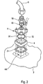
figure 2 montre des détails d'un capteur de pression qui est susceptible d'être surveillé par un dispositif .
- The
figure 1 is the block diagram of a device. - The
figure 2 shows details of a pressure sensor that is likely to be monitored by a device.
Le dispositif 1 et représenté schématiquement sur la
Plus précisément, ledit dispositif 1 est destiné à détecter toute obstruction d'une prise de pression 4A d'une sonde 4 d'au moins un capteur de pression statique 2 de l'aéronef.More specifically, said
On sait qu'un tel capteur de pression statique 2 fait généralement partie d'une centrale anémométrique 10 qui est destinée à mesurer des "données air" ("air data" en anglais) permettant de déterminer des valeurs de paramètres tels que l'altitude, la vitesse, ... de l'aéronef. Ces paramètres sont notamment utilisés pour le pilotage de l'aéronef. De façon usuelle, un capteur de pression statique 2 comporte :
une sonde 4 qui est monté, de façon traversante, sur lefuselage 3 de l'aéronef et accède à l'extérieur par l'intermédiaire d'une prise de pression 4A ;un module 5 qui est reliépar une tuyauterie 6 à lasonde 4. Généralement, la tuyauterie 6 qui réalise une liaison pneumatique est connectée aumodule 5 au moyen d'un connecteur pneumatique 7 qui permet de le déconnecter et le reconnecter facilement et rapidement. De plus, un convertisseur analogique/numérique 8 peut être associéaudit module 5 ; et- un système de chauffage 9 usuel, qui est susceptible de chauffer ladite sonde 4 et qui est actionnable manuellement et/ou automatiquement.
- a
probe 4 which is mounted, through, on thefuselage 3 of the aircraft and accesses the outside through apressure tap 4A; - a
module 5 which is connected by apipe 6 to theprobe 4. Generally, thepipe 6 which makes a pneumatic connection is connected to themodule 5 by means of apneumatic connector 7 which allows to disconnect and reconnect easily and quickly. In addition, a analog /digital converter 8 may be associated with saidmodule 5; and - a
conventional heating system 9, which is capable of heating saidprobe 4 and which can be actuated manually and / or automatically.
Pour détecter une défaillance du capteur de pression statique 2 due au fait que la prise de pression 4A est obstruée (ou bouchée), ledit dispositif 1 comporte :
- au moins ledit capteur de pression statique 2 surveillé. Ce capteur de pression statique 2 est formé pour réaliser :
- ■ dès l'activation dudit système de chauffage 9, une première mesure d'au moins un paramètre précisé ci-dessous, qui dépend de la pression à l'intérieur de ladite sonde 4 ; et
- ■ une première durée prédéterminée après cette activation du système de chauffage 9, une seconde mesure dudit même paramètre ;
- au moins une unité centrale 11 qui est reliée par une
liaison 12audit module 5, pour calculer la différence entre lesdites première et seconde mesures et comparer cette différence à une valeur prédéterminée précisée ci-dessous ; et - des moyens d'alerte 13 qui sont reliés par une
liaison 14 à ladite unité centrale 11, pour émettre un signal d'alerte (visuel et/ou sonore) signalant la détection d'une obstruction, si l'unité centrale 11 leur indique que la différence précitée est supérieure à ladite valeur prédéterminée.
- at least said
static pressure sensor 2 monitored. Thisstatic pressure sensor 2 is formed to produce:- ■ upon activation of said
heating system 9, a first measurement of at least one parameter specified below, which depends on the pressure inside saidprobe 4; and - A first predetermined duration after this activation of the
heating system 9, a second measurement of the same parameter;
- ■ upon activation of said
- at least one
central unit 11 which is connected by alink 12 to saidmodule 5, to calculate the difference between said first and second measurements and to compare this difference with a predetermined value specified below; and - warning means 13 which are connected by a
link 14 to saidcentral unit 11, to emit an alert signal (visual and / or audible) signaling the detection of an obstruction, if thecentral unit 11 indicates to them that the aforementioned difference is greater than said predetermined value.
Lesdits moyens d'alerte 13 émettent un signal d'alerte, uniquement si ladite différence est supérieure à ladite valeur prédéterminée pendant au moins une seconde durée prédéterminée, également précisée ci-dessous.Said warning means 13 emit an alert signal, only if said difference is greater than said predetermined value for at least a second predetermined duration, also specified below.
Le dispositif 1 prend donc en compte le fait que si la prise de pression 4A de la sonde 4 est bouchée ou obstruée, par exemple par un morceau de ruban adhésif, l'air qui est emprisonné à l'intérieur de cette sonde 4 (et de la tuyauterie 6) va s'échauffer dès que le système de chauffage 9 de la sonde 4 est activé de sorte que la pression statique à l'intérieur de la sonde 4 (et de la tuyauterie 6) qui est mesurée par le capteur de pression statique 2 va alors augmenter très rapidement et de façon significative. Cette augmentation peut être détectée par le dispositif 1, soit en surveillant directement la pression statique mesurée, soit en surveillant un autre paramètre (notamment l'altitude barométrique) qui dépend de cette pression statique et varie anormalement quand cette dernière varie anormalement.The
Comme de façon usuelle le système de chauffage 9 de la sonde 4 est activé au sol, généralement dès la mise en marche d'au moins un moteur (non représenté) de l'aéronef ou lorsque l'aéronef commence à rouler ou lorsque l'équipage enclenche le bouton poussoir du réchauffage des sondes ("Probe/Windows Heat Push Button" en anglais), le dispositif 1 est en mesure de détecter l'obstruction de la prise de pression 4A de cette sonde 4, lorsque l'aéronef se trouve encore au sol. Aussi, en cas de détection d'une telle obstruction au sol, le personnel de maintenance peut rapidement déboucher la sonde 4 obstruée, et ceci avant le décollage de l'aéronef. Le capteur de pression statique 2 défaillant est donc rapidement réparé et remis en fonctionnement normal, et il peut être utilisé dès le vol qui est prévu.As usual, the
Le dispositif 1 comporte, de plus, un moyen 16 pour réaliser une surveillance de l'état d'activation dudit système de chauffage 9 du capteur de pression statique 2 surveillé. Ce moyen 16 informe le dispositif 1 dès qu'il détecte l'activation dudit système de chauffage 9 de sorte que le dispositif 1 peut alors réaliser les mesures nécessaires précitées. Pour ce faire, ledit moyen 16 peut en particulier surveiller la mise en marche d'un premier moteur de l'aéronef et/ou l'activation d'un système de chauffage général et/ou le début du roulage de l'aéronef.The
Bien entendu, le dispositif 1 peut surveiller simultanément plusieurs capteurs de pression statique 2.Of course, the
On sait que, généralement, une centrale anémométrique 10 d'un aéronef est reliée à au moins deux capteurs de pression statique 2, dont les prises de pression 4A sont montées de part et d'autre de l'axe longitudinal 17 du fuselage 3 de l'aéronef, comme représenté sur la
On notera de plus qu'un avion de transport civil comporte généralement trois centrales anémométriques 10 de ce type, dont :
- une première fournit des données qui sont affichées dans le poste de pilotage, à l'attention du pilote ;
- une deuxième fournit des données qui sont affichées dans le poste de pilotage, à l'attention du copilote ; et
- une troisième est utilisée en secours pour parer, le cas échéant, la défaillance desdites première et deuxième centrales anémométriques 10.
- a first provides data that is displayed in the cockpit, for the attention of the pilot;
- a second provides data that is displayed in the cockpit, for the co-pilot's attention; and
- a third is used as a backup to counter, if necessary, the failure of said first and second
central air 10.
Le dispositif 1 peut surveiller tous les capteurs de pression statique 2 d'une centrale anémométrique 10 ou tous les capteurs de pression statique 2 de l'ensemble des centrales anémométriques 10 de l'aéronef. Pour ce faire, il comporte à chaque fois les capteurs de pression statique 2 qu'il surveille.The
On notera que la liaison 12 permettant de relier un module 5 à l'unité centrale 11 est une liaison électrique, réalisée de préférence sous forme d'un bus de communication au standard "ARINC 429". Il est également envisageable d'intégrer différents modules 5 directement dans l'unité centrale 11.Note that the
Sur la
un raccord 18 à vis ;une rondelle 19 ;- le système de chauffage 9 qui est de préférence de type électrique ;
une rondelle 20 ;la sonde 4 de pression statique ; etune rondelle 21,
- a
screw connection 18; - a
washer 19; - the
heating system 9 which is preferably of the electric type; - a
washer 20; -
static pressure probe 4; and - a
washer 21,
En outre, ladite unité centrale 11 peut faire partie notamment :
- d'un calculateur central d'alarme, de type "FWC" ("Flight Warning Computer" en anglais) ; ou
- d'une unité de référence inertielle et de données anémométriques, de type "ADIRU" ("Air Data Inertial Reference Unit" en anglais).
- a central alarm computer, type "FWC"("Flight Warning Computer" in English); or
- an inertial reference unit and anemometric data, of the "ADIRU" type ("Air Data Inertial Reference Unit" in English).
Par ailleurs, lesdits moyens d'alerte 13 comportent un écran 15, en particulier un écran d'affichage de messages d'alerte de type "ECAM" ("Electronic Centralized Aircraft Monitoring" en anglais).Moreover, said warning means 13 comprise a
Le paramètre mesuré par le dispositif 1 représente l'altitude barométrique de l'aéronef. Le dispositif 1 a alors pour objet de détecter toute variation d'altitude barométrique importante et soudaine, lors de l'activation du (ou des) système(s) de chauffage 9 du (ou des) capteur(s) de pression statique 2 surveillé(s). Dans ce cas, de préférence, le dispositif 1 surveille et comporte deux capteurs de pression statique 2, et chacune des première et seconde mesures de l'altitude barométrique est réalisée à l'aide de données air fournies par chacun de ces deux capteurs de pression statique 2. L'altitude barométrique est alors calculée à chaque fois, de façon usuelle, à partir de la pression statique moyenne des mesures de pression statique réalisées par ces deux capteurs de pression statique 2 qui sont situés, de préférence, à droite et à gauche de l'aéronef.The parameter measured by the
De plus, on peut utiliser, à titre d'exemple, les valeurs prédéterminées suivantes :
- comme première durée prédéterminée : 60 secondes ;
- comme valeur prédéterminée d'altitude barométrique, à laquelle on compare la différence d'altitude barométrique entre les première et seconde mesures réalisées : 20 pieds (environ 6 mètres) ; et
- comme seconde durée prédéterminée : 5 secondes.
- as a first predetermined duration: 60 seconds;
- as a predetermined barometric altitude value, to which the difference in barometric altitude between the first and second measured measurements is compared: 20 feet (about 6 meters); and
- as a second predetermined duration: 5 seconds.
En outre, le paramètre mesuré par le dispositif 1 représente le taux de variation de l'altitude barométrique.In addition, the parameter measured by the
Par ailleurs, le dispositif 1 utilise, comme paramètre surveillé, la pression statique qui est mesurée directement par le (ou les) capteur(s) de pression statique 2 surveillé(s), c'est-à-dire la pression statique qui existe à l'intérieur de la sonde 4 et de la tuyauterie 6 de chaque capteur de pression statique 2 surveillée.Moreover, the
On peut utiliser à titre d'exemple les valeurs prédéterminées suivantes :
- comme première durée prédéterminée : 75 secondes ;
- comme valeur prédéterminée de pression statique, à laquelle on compare la différence entre les première et seconde mesures de pression statique : 1 mbar ; et
- comme seconde durée prédéterminée : 10 secondes.
- as a first predetermined duration: 75 seconds;
- as a predetermined value of static pressure, to which the difference between the first and second static pressure measurements is compared: 1 mbar; and
- as a second predetermined duration: 10 seconds.
Le dispositif 1 permet donc de réaliser une surveillance efficace et robuste d'au moins un capteur de pression statique 2 d'un aéronef.The
Claims (7)
- A method for detecting the obstruction of a pressure tap (4A) of a probe (4) of at least one pressure sensor (2) of an aircraft, said pressure sensor (2) being provided to measure the pressure inside the probe (4) and comprising, in addition to said probe (4), at least one activatable heating system (9) provided to heat the latter, method according to which:a) on activation of the heating system (9) of at least one pressure sensor (2), a first measurement is taken using said pressure sensor (2) of at least one parameter dependent on the pressure inside said probe (4);b) a first predetermined duration after said activation of the heating system (9), a second measurement of said parameter is taken using said pressure sensor (2);c) the difference between said first and second measurements is calculated;d) the duly calculated difference is compared with a predetermined value; ande) if this difference is greater than said predetermined value, an alert signal is emitted, indicating the detection of an obstruction.
- The method as claimed in claim 1,
characterized in that monitoring of the state of activation of said heating system (9) of the pressure sensor (2) is implemented, and in that, in the step a), said first measurement is taken immediately the activation of said heating system (9) is detected thanks to said monitoring. - The method as claimed in one of claims 1 and 2,
characterized in that, in the step e), a warning signal is emitted only if said difference is greater than said predetermined value for at least one second predetermined duration. - The method as claimed in one of claims 1 to 3,
characterized in that said parameter represents the barometric altitude. - The method as claimed in claim 4,
characterized in that two pressure sensors (2) are used, and in that each of said first and second measurements of the barometric altitude is taken using air data supplied by these two pressure sensors (2). - The method as claimed in one of claims 1 to 3,
characterized in that said parameter represents the barometric altitude rate. - The method as claimed in one of claims 1 to 3,
characterized in that said parameter corresponds to the static pressure present inside the probe (4).
Applications Claiming Priority (2)
| Application Number | Priority Date | Filing Date | Title |
|---|---|---|---|
| FR0501453A FR2882141B1 (en) | 2005-02-14 | 2005-02-14 | METHOD AND DEVICE FOR DETECTING IN THE GROUND THE OBSTRUCTION OF A PRESSURE SOCKET OF A STATIC PRESSURE SENSOR OF AN AIRCRAFT |
| PCT/FR2006/000228 WO2006087440A1 (en) | 2005-02-14 | 2006-02-02 | Method and device for detecting, on the ground, the obstruction of a pressure tap of a static pressure sensor of an aircraft |
Publications (2)
| Publication Number | Publication Date |
|---|---|
| EP1848976A1 EP1848976A1 (en) | 2007-10-31 |
| EP1848976B1 true EP1848976B1 (en) | 2012-05-02 |
Family
ID=35045428
Family Applications (1)
| Application Number | Title | Priority Date | Filing Date |
|---|---|---|---|
| EP06709220A Not-in-force EP1848976B1 (en) | 2005-02-14 | 2006-02-02 | Method and device for detecting, on the ground, the obstruction of a pressure tap of a static pressure sensor of an aircraft |
Country Status (10)
| Country | Link |
|---|---|
| US (1) | US7675434B2 (en) |
| EP (1) | EP1848976B1 (en) |
| JP (1) | JP5166884B2 (en) |
| CN (1) | CN100559139C (en) |
| AT (1) | ATE556305T1 (en) |
| BR (1) | BRPI0606554A2 (en) |
| CA (1) | CA2596928C (en) |
| FR (1) | FR2882141B1 (en) |
| RU (1) | RU2354947C1 (en) |
| WO (1) | WO2006087440A1 (en) |
Families Citing this family (15)
| Publication number | Priority date | Publication date | Assignee | Title |
|---|---|---|---|---|
| US8290631B2 (en) * | 2009-03-12 | 2012-10-16 | Emerson Process Management Power & Water Solutions, Inc. | Methods and apparatus to arbitrate valve position sensor redundancy |
| JP5175002B2 (en) * | 2009-04-21 | 2013-04-03 | インディアン・スペース・リサーチ・オーガニゼイション | System and method for detecting and isolating faults in pressure sensing of flash atmospheric data systems (FADS) |
| FR2964210B1 (en) * | 2010-08-24 | 2012-09-21 | Airbus Operations Sas | REDUNDANT SIGNAL PROCESSING SYSTEM, ASSOCIATED METHOD, AND AIRCRAFT COMPRISING SUCH A SYSTEM |
| US8718955B2 (en) * | 2010-11-15 | 2014-05-06 | Rosemount Aerospace Inc. | System and method for detecting blocked pitot-static ports |
| FR2976374B1 (en) | 2011-06-10 | 2016-10-14 | Thales Sa | OPTIMIZED TASK TREATMENT METHOD AND DEVICE FOR FWS. |
| FR2999293B1 (en) * | 2012-12-11 | 2015-01-16 | Thales Sa | SYSTEM FOR PROVIDING FLIGHT PARAMETERS ESTIMATES OF AN INDEPENDENT AND DISSIMILAR AIRCRAFT AND ASSOCIATED AIRCRAFT |
| FR3009281B1 (en) * | 2013-07-31 | 2017-02-17 | Airbus Operations Sas | AIRCRAFT COMPRISING A PRESSURE MEASURING SYSTEM AND METHOD THEREOF |
| CA2920449C (en) * | 2013-08-08 | 2021-12-28 | Bombardier Inc. | Air data probe contamination monitor |
| JP2015132646A (en) | 2014-01-09 | 2015-07-23 | 三星電子株式会社Samsung Electronics Co.,Ltd. | Magenta toner for electrostatic charge image development |
| CN104655364B (en) * | 2015-03-13 | 2017-10-27 | 中国航空工业集团公司北京长城计量测试技术研究所 | Partial pressure mode high static pressure differential pressure generating and method |
| CN105973544B (en) * | 2016-06-20 | 2018-04-10 | 中国民航大学 | A kind of aircraft pitot-static pressure test system and method based on self-adaptive PID method |
| DE102016114846A1 (en) * | 2016-08-10 | 2018-02-15 | Endress+Hauser Gmbh+Co. Kg | Differential pressure measuring arrangement and method for detecting clogged differential pressure lines |
| CN111720671A (en) * | 2019-03-18 | 2020-09-29 | 成都飞机工业(集团)有限责任公司 | Novel L-shaped pressure sensor clamp |
| CN112067193B (en) * | 2020-09-14 | 2022-03-25 | 中国空气动力研究与发展中心超高速空气动力研究所 | Aircraft surface pressure sensor testing device and testing method |
| CN113848977B (en) * | 2021-10-09 | 2023-12-22 | 广东汇天航空航天科技有限公司 | Aircraft control method and system and flight controller |
Family Cites Families (15)
| Publication number | Priority date | Publication date | Assignee | Title |
|---|---|---|---|---|
| GB2049954A (en) * | 1979-05-22 | 1980-12-31 | Russell J | Improvements in or relating to apparatus for testing aircraft instruments |
| US4598381A (en) * | 1983-03-24 | 1986-07-01 | Rosemount Inc. | Pressure compensated differential pressure sensor and method |
| DE3618798A1 (en) * | 1986-06-04 | 1987-12-10 | Nord Micro Elektronik Feinmech | Method for measuring a physical quantity influencing the inherent oscillation of a measurement transducer |
| FR2686310B1 (en) * | 1992-01-20 | 1994-04-08 | Aerospatiale Ste Nationale Indle | SYSTEM FOR CONTROLLING AN AERODYNAMIC SURFACE OF AN AIRCRAFT. |
| FR2703155B1 (en) * | 1993-03-25 | 1995-06-09 | Aerospatiale | Integrated system for multi-channel pressure measurements and corresponding measurement method. |
| JP2001505659A (en) * | 1996-10-16 | 2001-04-24 | ローズマウント・エアロスペース・インコーポレーテッド | Heated air data probe |
| JP3628711B2 (en) * | 1997-03-20 | 2005-03-16 | イノヴァティヴ ソルーションズ アンド サポート インコーポレーテッド | Air data measurement system with circuitry to linearize pressure transducer output |
| US6701274B1 (en) * | 1999-08-27 | 2004-03-02 | Rosemount Inc. | Prediction of error magnitude in a pressure transmitter |
| US6414282B1 (en) * | 2000-11-01 | 2002-07-02 | Rosemount Aerospace Inc. | Active heater control circuit and method used for aerospace probes |
| US6609421B2 (en) * | 2001-05-08 | 2003-08-26 | Rosemount Aerospace Inc. | Sideslip correction for a multi-function three probe air data system |
| JP3718847B2 (en) * | 2002-05-17 | 2005-11-24 | 横河電機株式会社 | Differential pressure measuring device |
| US6668640B1 (en) * | 2002-08-12 | 2003-12-30 | Rosemount Aerospace Inc. | Dual-channel electronic multi-function probes and methods for realizing dissimilar and independent air data outputs |
| FR2847669B1 (en) * | 2002-11-27 | 2005-02-04 | Airbus France | METHOD AND DEVICE FOR DETECTING THE FAILURE OF A PRESSURE SENSOR OF AN ANEMOMETRIC CENTRAL OF AN AIRCRAFT |
| FR2857447B1 (en) * | 2003-07-07 | 2005-09-30 | Airbus France | METHOD AND DEVICE FOR MONITORING THE VALIDITY OF AT LEAST ONE PARAMETER CALCULATED BY AN ANEMOMETRIC CENTRAL OF AN AIRCRAFT |
| US6804600B1 (en) * | 2003-09-05 | 2004-10-12 | Honeywell International, Inc. | Sensor error detection and compensation system and method |
-
2005
- 2005-02-14 FR FR0501453A patent/FR2882141B1/en not_active Expired - Fee Related
-
2006
- 2006-02-02 CA CA2596928A patent/CA2596928C/en not_active Expired - Fee Related
- 2006-02-02 WO PCT/FR2006/000228 patent/WO2006087440A1/en active Application Filing
- 2006-02-02 US US11/816,078 patent/US7675434B2/en active Active
- 2006-02-02 RU RU2007134225/28A patent/RU2354947C1/en not_active IP Right Cessation
- 2006-02-02 BR BRPI0606554-6A patent/BRPI0606554A2/en not_active IP Right Cessation
- 2006-02-02 EP EP06709220A patent/EP1848976B1/en not_active Not-in-force
- 2006-02-02 CN CN200680004695.4A patent/CN100559139C/en not_active Expired - Fee Related
- 2006-02-02 AT AT06709220T patent/ATE556305T1/en active
- 2006-02-02 JP JP2007554592A patent/JP5166884B2/en not_active Expired - Fee Related
Also Published As
| Publication number | Publication date |
|---|---|
| BRPI0606554A2 (en) | 2009-06-30 |
| CN100559139C (en) | 2009-11-11 |
| FR2882141B1 (en) | 2007-05-04 |
| JP5166884B2 (en) | 2013-03-21 |
| ATE556305T1 (en) | 2012-05-15 |
| CA2596928C (en) | 2016-11-15 |
| CA2596928A1 (en) | 2006-08-24 |
| US7675434B2 (en) | 2010-03-09 |
| RU2354947C1 (en) | 2009-05-10 |
| US20080150763A1 (en) | 2008-06-26 |
| EP1848976A1 (en) | 2007-10-31 |
| FR2882141A1 (en) | 2006-08-18 |
| WO2006087440A1 (en) | 2006-08-24 |
| JP2008530545A (en) | 2008-08-07 |
| CN101120238A (en) | 2008-02-06 |
Similar Documents
| Publication | Publication Date | Title |
|---|---|---|
| EP1848976B1 (en) | Method and device for detecting, on the ground, the obstruction of a pressure tap of a static pressure sensor of an aircraft | |
| EP2568295B1 (en) | Method and apparatus for the automatic estimation of airspeed of an aircraft | |
| EP2921863B1 (en) | Method and device for automatically estimating parameters linked to the flight of an aircraft | |
| US9857272B2 (en) | Systems and methods for detecting wheel bearing wear with mounted accelerometers | |
| FR2889342A1 (en) | METHOD AND DEVICE FOR DETECTING A RISK OF COLLISION OF AN AIRCRAFT WITH THE SURROUNDING FIELD | |
| FR2901893A1 (en) | Aircraft`s e.g. airbus A320 type civil transport aircraft, control information e.g. commanded roll, monitoring device, has alerting system generating signal when difference between control information is higher than preset threshold value | |
| EP1498737B1 (en) | Method and device for monitoring the correctness of speed values in an airplane | |
| EP1496414B1 (en) | Device and method for controlling the validity of at least one parameter calculated by an aircraft anemometer station | |
| EP2452162B1 (en) | Excitation circuit for dc sensors | |
| FR3076612A1 (en) | SYSTEM AND METHOD FOR DETECTING BLOCKING OF A PITOT TUBE | |
| EP1429131B1 (en) | Procedure and apparatus for detection of the malfunction of a pressure sensor of an aircraft anemometer station | |
| EP1607245B1 (en) | Method to detect a fast tyre air leak | |
| FR2937009A1 (en) | METHOD AND SYSTEM FOR METEOROLOGICAL MONITORING ON BOARD AN AIRCRAFT. | |
| FR2903385A1 (en) | RELIEF INSTRUMENT FOR AN AIRCRAFT DASHBOARD WITH RELIABLE MAINTENANCE | |
| EP0230182A1 (en) | Process for monitoring cracks susceptible to be produced in structures subject to stress | |
| EP3771649A1 (en) | System for evaluating the clogging of a filter equipping an aircraft, aircraft comprising such an evaluation system and associated method | |
| FR3014752A1 (en) | TIRE PRESSURE MONITORING SYSTEM OF A MOTOR VEHICLE | |
| FR2932881A1 (en) | METHOD OF DETECTING FAILURE OF AN ANALOGUE SENSOR AND DETECTION DEVICE FOR CARRYING OUT SAID METHOD | |
| FR2997495A1 (en) | METHOD FOR MONITORING VIBRATORY SENSORS | |
| CA2951490C (en) | Method for assisting with the detection of damage to a turbojet duct | |
| EP3182287B1 (en) | A method and a system for monitoring the reliability of at least one piece of electronic equipment installed in an aircraft | |
| FR3078811A1 (en) | METHOD FOR DYNAMICALLY DETERMINING THE POSITION OF THE STOPPING POINT OF AN AIRCRAFT ON A LANDING TRACK AND ASSOCIATED SYSTEM | |
| FR2851047A1 (en) | Vehicle speed data control device has ground sensor measuring vehicle speed relative to ground, and calculator obtaining correction coefficient by comparing speed values from the sensor and a component measuring wheel rotation speed | |
| FR3037404A1 (en) | METHOD AND DEVICE FOR AUTOMATICALLY MONITORING A VALUE GENERATED BY AN ANEMOMETRIC SYSTEM OF AN AIRCRAFT |
Legal Events
| Date | Code | Title | Description |
|---|---|---|---|
| PUAI | Public reference made under article 153(3) epc to a published international application that has entered the european phase |
Free format text: ORIGINAL CODE: 0009012 |
|
| 17P | Request for examination filed |
Effective date: 20070727 |
|
| AK | Designated contracting states |
Kind code of ref document: A1 Designated state(s): AT BE BG CH CY CZ DE DK EE ES FI FR GB GR HU IE IS IT LI LT LU LV MC NL PL PT RO SE SI SK TR |
|
| DAX | Request for extension of the european patent (deleted) | ||
| RAP1 | Party data changed (applicant data changed or rights of an application transferred) |
Owner name: AIRBUS OPERATIONS |
|
| RAP1 | Party data changed (applicant data changed or rights of an application transferred) |
Owner name: AIRBUS OPERATIONS (SAS) |
|
| 17Q | First examination report despatched |
Effective date: 20100827 |
|
| GRAP | Despatch of communication of intention to grant a patent |
Free format text: ORIGINAL CODE: EPIDOSNIGR1 |
|
| GRAS | Grant fee paid |
Free format text: ORIGINAL CODE: EPIDOSNIGR3 |
|
| GRAA | (expected) grant |
Free format text: ORIGINAL CODE: 0009210 |
|
| AK | Designated contracting states |
Kind code of ref document: B1 Designated state(s): AT BE BG CH CY CZ DE DK EE ES FI FR GB GR HU IE IS IT LI LT LU LV MC NL PL PT RO SE SI SK TR |
|
| REG | Reference to a national code |
Ref country code: GB Ref legal event code: FG4D Free format text: NOT ENGLISH |
|
| REG | Reference to a national code |
Ref country code: CH Ref legal event code: EP Ref country code: AT Ref legal event code: REF Ref document number: 556305 Country of ref document: AT Kind code of ref document: T Effective date: 20120515 |
|
| REG | Reference to a national code |
Ref country code: IE Ref legal event code: FG4D Free format text: LANGUAGE OF EP DOCUMENT: FRENCH |
|
| REG | Reference to a national code |
Ref country code: DE Ref legal event code: R096 Ref document number: 602006029223 Country of ref document: DE Effective date: 20120628 |
|
| REG | Reference to a national code |
Ref country code: NL Ref legal event code: VDEP Effective date: 20120502 |
|
| REG | Reference to a national code |
Ref country code: LT Ref legal event code: MG4D Effective date: 20120502 |
|
| PG25 | Lapsed in a contracting state [announced via postgrant information from national office to epo] |
Ref country code: CY Free format text: LAPSE BECAUSE OF FAILURE TO SUBMIT A TRANSLATION OF THE DESCRIPTION OR TO PAY THE FEE WITHIN THE PRESCRIBED TIME-LIMIT Effective date: 20120502 Ref country code: FI Free format text: LAPSE BECAUSE OF FAILURE TO SUBMIT A TRANSLATION OF THE DESCRIPTION OR TO PAY THE FEE WITHIN THE PRESCRIBED TIME-LIMIT Effective date: 20120502 Ref country code: IS Free format text: LAPSE BECAUSE OF FAILURE TO SUBMIT A TRANSLATION OF THE DESCRIPTION OR TO PAY THE FEE WITHIN THE PRESCRIBED TIME-LIMIT Effective date: 20120902 Ref country code: LT Free format text: LAPSE BECAUSE OF FAILURE TO SUBMIT A TRANSLATION OF THE DESCRIPTION OR TO PAY THE FEE WITHIN THE PRESCRIBED TIME-LIMIT Effective date: 20120502 Ref country code: PL Free format text: LAPSE BECAUSE OF FAILURE TO SUBMIT A TRANSLATION OF THE DESCRIPTION OR TO PAY THE FEE WITHIN THE PRESCRIBED TIME-LIMIT Effective date: 20120502 Ref country code: SE Free format text: LAPSE BECAUSE OF FAILURE TO SUBMIT A TRANSLATION OF THE DESCRIPTION OR TO PAY THE FEE WITHIN THE PRESCRIBED TIME-LIMIT Effective date: 20120502 |
|
| REG | Reference to a national code |
Ref country code: AT Ref legal event code: MK05 Ref document number: 556305 Country of ref document: AT Kind code of ref document: T Effective date: 20120502 |
|
| PG25 | Lapsed in a contracting state [announced via postgrant information from national office to epo] |
Ref country code: LV Free format text: LAPSE BECAUSE OF FAILURE TO SUBMIT A TRANSLATION OF THE DESCRIPTION OR TO PAY THE FEE WITHIN THE PRESCRIBED TIME-LIMIT Effective date: 20120502 Ref country code: SI Free format text: LAPSE BECAUSE OF FAILURE TO SUBMIT A TRANSLATION OF THE DESCRIPTION OR TO PAY THE FEE WITHIN THE PRESCRIBED TIME-LIMIT Effective date: 20120502 Ref country code: PT Free format text: LAPSE BECAUSE OF FAILURE TO SUBMIT A TRANSLATION OF THE DESCRIPTION OR TO PAY THE FEE WITHIN THE PRESCRIBED TIME-LIMIT Effective date: 20120903 Ref country code: GR Free format text: LAPSE BECAUSE OF FAILURE TO SUBMIT A TRANSLATION OF THE DESCRIPTION OR TO PAY THE FEE WITHIN THE PRESCRIBED TIME-LIMIT Effective date: 20120803 |
|
| PG25 | Lapsed in a contracting state [announced via postgrant information from national office to epo] |
Ref country code: CZ Free format text: LAPSE BECAUSE OF FAILURE TO SUBMIT A TRANSLATION OF THE DESCRIPTION OR TO PAY THE FEE WITHIN THE PRESCRIBED TIME-LIMIT Effective date: 20120502 Ref country code: AT Free format text: LAPSE BECAUSE OF FAILURE TO SUBMIT A TRANSLATION OF THE DESCRIPTION OR TO PAY THE FEE WITHIN THE PRESCRIBED TIME-LIMIT Effective date: 20120502 Ref country code: SK Free format text: LAPSE BECAUSE OF FAILURE TO SUBMIT A TRANSLATION OF THE DESCRIPTION OR TO PAY THE FEE WITHIN THE PRESCRIBED TIME-LIMIT Effective date: 20120502 Ref country code: RO Free format text: LAPSE BECAUSE OF FAILURE TO SUBMIT A TRANSLATION OF THE DESCRIPTION OR TO PAY THE FEE WITHIN THE PRESCRIBED TIME-LIMIT Effective date: 20120502 Ref country code: DK Free format text: LAPSE BECAUSE OF FAILURE TO SUBMIT A TRANSLATION OF THE DESCRIPTION OR TO PAY THE FEE WITHIN THE PRESCRIBED TIME-LIMIT Effective date: 20120502 Ref country code: NL Free format text: LAPSE BECAUSE OF FAILURE TO SUBMIT A TRANSLATION OF THE DESCRIPTION OR TO PAY THE FEE WITHIN THE PRESCRIBED TIME-LIMIT Effective date: 20120502 Ref country code: EE Free format text: LAPSE BECAUSE OF FAILURE TO SUBMIT A TRANSLATION OF THE DESCRIPTION OR TO PAY THE FEE WITHIN THE PRESCRIBED TIME-LIMIT Effective date: 20120502 |
|
| PLBE | No opposition filed within time limit |
Free format text: ORIGINAL CODE: 0009261 |
|
| STAA | Information on the status of an ep patent application or granted ep patent |
Free format text: STATUS: NO OPPOSITION FILED WITHIN TIME LIMIT |
|
| 26N | No opposition filed |
Effective date: 20130205 |
|
| PG25 | Lapsed in a contracting state [announced via postgrant information from national office to epo] |
Ref country code: ES Free format text: LAPSE BECAUSE OF FAILURE TO SUBMIT A TRANSLATION OF THE DESCRIPTION OR TO PAY THE FEE WITHIN THE PRESCRIBED TIME-LIMIT Effective date: 20120813 |
|
| REG | Reference to a national code |
Ref country code: DE Ref legal event code: R097 Ref document number: 602006029223 Country of ref document: DE Effective date: 20130205 |
|
| PG25 | Lapsed in a contracting state [announced via postgrant information from national office to epo] |
Ref country code: BG Free format text: LAPSE BECAUSE OF FAILURE TO SUBMIT A TRANSLATION OF THE DESCRIPTION OR TO PAY THE FEE WITHIN THE PRESCRIBED TIME-LIMIT Effective date: 20120802 |
|
| BERE | Be: lapsed |
Owner name: AIRBUS OPERATIONS (SAS) Effective date: 20130228 |
|
| PG25 | Lapsed in a contracting state [announced via postgrant information from national office to epo] |
Ref country code: MC Free format text: LAPSE BECAUSE OF NON-PAYMENT OF DUE FEES Effective date: 20130228 |
|
| REG | Reference to a national code |
Ref country code: CH Ref legal event code: PL |
|
| PG25 | Lapsed in a contracting state [announced via postgrant information from national office to epo] |
Ref country code: LI Free format text: LAPSE BECAUSE OF NON-PAYMENT OF DUE FEES Effective date: 20130228 Ref country code: CH Free format text: LAPSE BECAUSE OF NON-PAYMENT OF DUE FEES Effective date: 20130228 |
|
| REG | Reference to a national code |
Ref country code: IE Ref legal event code: MM4A |
|
| PG25 | Lapsed in a contracting state [announced via postgrant information from national office to epo] |
Ref country code: IE Free format text: LAPSE BECAUSE OF NON-PAYMENT OF DUE FEES Effective date: 20130202 Ref country code: BE Free format text: LAPSE BECAUSE OF NON-PAYMENT OF DUE FEES Effective date: 20130228 |
|
| REG | Reference to a national code |
Ref country code: FR Ref legal event code: PLFP Year of fee payment: 10 |
|
| PG25 | Lapsed in a contracting state [announced via postgrant information from national office to epo] |
Ref country code: TR Free format text: LAPSE BECAUSE OF FAILURE TO SUBMIT A TRANSLATION OF THE DESCRIPTION OR TO PAY THE FEE WITHIN THE PRESCRIBED TIME-LIMIT Effective date: 20120502 |
|
| PG25 | Lapsed in a contracting state [announced via postgrant information from national office to epo] |
Ref country code: HU Free format text: LAPSE BECAUSE OF FAILURE TO SUBMIT A TRANSLATION OF THE DESCRIPTION OR TO PAY THE FEE WITHIN THE PRESCRIBED TIME-LIMIT; INVALID AB INITIO Effective date: 20060202 Ref country code: LU Free format text: LAPSE BECAUSE OF NON-PAYMENT OF DUE FEES Effective date: 20130202 |
|
| REG | Reference to a national code |
Ref country code: FR Ref legal event code: PLFP Year of fee payment: 11 |
|
| REG | Reference to a national code |
Ref country code: FR Ref legal event code: PLFP Year of fee payment: 12 |
|
| REG | Reference to a national code |
Ref country code: FR Ref legal event code: PLFP Year of fee payment: 13 |
|
| PGFP | Annual fee paid to national office [announced via postgrant information from national office to epo] |
Ref country code: ES Payment date: 20190102 Year of fee payment: 15 |
|
| PGFP | Annual fee paid to national office [announced via postgrant information from national office to epo] |
Ref country code: DE Payment date: 20200219 Year of fee payment: 15 |
|
| REG | Reference to a national code |
Ref country code: DE Ref legal event code: R119 Ref document number: 602006029223 Country of ref document: DE |
|
| PG25 | Lapsed in a contracting state [announced via postgrant information from national office to epo] |
Ref country code: IT Free format text: LAPSE BECAUSE OF NON-PAYMENT OF DUE FEES Effective date: 20200202 |
|
| PG25 | Lapsed in a contracting state [announced via postgrant information from national office to epo] |
Ref country code: DE Free format text: LAPSE BECAUSE OF NON-PAYMENT OF DUE FEES Effective date: 20210901 |
|
| PGFP | Annual fee paid to national office [announced via postgrant information from national office to epo] |
Ref country code: GB Payment date: 20220223 Year of fee payment: 17 |
|
| PGFP | Annual fee paid to national office [announced via postgrant information from national office to epo] |
Ref country code: FR Payment date: 20220216 Year of fee payment: 17 |
|
| GBPC | Gb: european patent ceased through non-payment of renewal fee |
Effective date: 20230202 |
|
| PG25 | Lapsed in a contracting state [announced via postgrant information from national office to epo] |
Ref country code: GB Free format text: LAPSE BECAUSE OF NON-PAYMENT OF DUE FEES Effective date: 20230202 |
|
| PG25 | Lapsed in a contracting state [announced via postgrant information from national office to epo] |
Ref country code: GB Free format text: LAPSE BECAUSE OF NON-PAYMENT OF DUE FEES Effective date: 20230202 Ref country code: FR Free format text: LAPSE BECAUSE OF NON-PAYMENT OF DUE FEES Effective date: 20230228 |