EP1848246A2 - Radio transmitting device and control device for event-halls and corresponding method - Google Patents
Radio transmitting device and control device for event-halls and corresponding method Download PDFInfo
- Publication number
- EP1848246A2 EP1848246A2 EP07105597A EP07105597A EP1848246A2 EP 1848246 A2 EP1848246 A2 EP 1848246A2 EP 07105597 A EP07105597 A EP 07105597A EP 07105597 A EP07105597 A EP 07105597A EP 1848246 A2 EP1848246 A2 EP 1848246A2
- Authority
- EP
- European Patent Office
- Prior art keywords
- radio
- control signal
- transmitter
- transmitting
- room
- Prior art date
- Legal status (The legal status is an assumption and is not a legal conclusion. Google has not performed a legal analysis and makes no representation as to the accuracy of the status listed.)
- Granted
Links
Images
Classifications
-
- H—ELECTRICITY
- H04—ELECTRIC COMMUNICATION TECHNIQUE
- H04R—LOUDSPEAKERS, MICROPHONES, GRAMOPHONE PICK-UPS OR LIKE ACOUSTIC ELECTROMECHANICAL TRANSDUCERS; DEAF-AID SETS; PUBLIC ADDRESS SYSTEMS
- H04R27/00—Public address systems
- H04R27/02—Amplifying systems for the deaf
-
- G—PHYSICS
- G09—EDUCATION; CRYPTOGRAPHY; DISPLAY; ADVERTISING; SEALS
- G09B—EDUCATIONAL OR DEMONSTRATION APPLIANCES; APPLIANCES FOR TEACHING, OR COMMUNICATING WITH, THE BLIND, DEAF OR MUTE; MODELS; PLANETARIA; GLOBES; MAPS; DIAGRAMS
- G09B5/00—Electrically-operated educational appliances
- G09B5/04—Electrically-operated educational appliances with audible presentation of the material to be studied
-
- H—ELECTRICITY
- H04—ELECTRIC COMMUNICATION TECHNIQUE
- H04R—LOUDSPEAKERS, MICROPHONES, GRAMOPHONE PICK-UPS OR LIKE ACOUSTIC ELECTROMECHANICAL TRANSDUCERS; DEAF-AID SETS; PUBLIC ADDRESS SYSTEMS
- H04R25/00—Deaf-aid sets, i.e. electro-acoustic or electro-mechanical hearing aids; Electric tinnitus maskers providing an auditory perception
- H04R25/55—Deaf-aid sets, i.e. electro-acoustic or electro-mechanical hearing aids; Electric tinnitus maskers providing an auditory perception using an external connection, either wireless or wired
- H04R25/554—Deaf-aid sets, i.e. electro-acoustic or electro-mechanical hearing aids; Electric tinnitus maskers providing an auditory perception using an external connection, either wireless or wired using a wireless connection, e.g. between microphone and amplifier or using Tcoils
-
- H—ELECTRICITY
- H04—ELECTRIC COMMUNICATION TECHNIQUE
- H04R—LOUDSPEAKERS, MICROPHONES, GRAMOPHONE PICK-UPS OR LIKE ACOUSTIC ELECTROMECHANICAL TRANSDUCERS; DEAF-AID SETS; PUBLIC ADDRESS SYSTEMS
- H04R2205/00—Details of stereophonic arrangements covered by H04R5/00 but not provided for in any of its subgroups
- H04R2205/041—Adaptation of stereophonic signal reproduction for the hearing impaired
Definitions
- the present invention relates to a radio transmitting device for transmitting voice signals in a function room. Furthermore, the present invention relates to a control device for controlling a radio transmitter, with which voice signals can be transmitted in a function room. Furthermore, the present invention relates to corresponding methods for transmitting speech signals and for controlling radio transmitters.
- FM systems frequency modulation
- the teacher usually wears a microphone with a transmitter and the students a receiver, if necessary, with a connection to a hearing aid.
- the teacher leaves the room and forgets to switch off the microphone, the students can follow conversations that take place, for example, in the staff room. So the teacher must try to avoid turning off the microphone manually in time.
- Phonak has announced a FM multi-frequency system for schools.
- the receivers in a classroom are automatically tuned to a configured radio frequency.
- a frequency change takes place automatically at the receiver.
- the object of the present invention is to assist the teacher or another user of an FM transmitter to switch off the transmitter promptly when not in use.
- this object is achieved by a radio transmitting device for transmitting voice signals in a function room with a receiving device for receiving at least one control signal and a switching device for switching on and / or off the radio transmitting device as a function of the received control signal.
- the invention also provides a method for transmitting speech signals in a function room by receiving a control signal in the function room and / or at the entrance of the function room with a radio transmitter, on and / or off the radio transmitter for transmitting the voice signals in response to the received control signal.
- the reception of a control signal preferably takes place via radio or inductively.
- a control signal preferably takes place via radio or inductively.
- wireless transmission z. B. Bluetooth.
- other short-distance transmission systems such as infrared systems, conceivable.
- the radio transmitting device can have a configuration device with which the radio transmitting device can be automatically configured as a function of the received control signal.
- the radio transmitter can be automatically switched to a corresponding radio channel due to the control signal.
- a different radio channel can be set automatically in each room so that interference due to events in adjacent rooms can be avoided.
- the radio transmitting device may be equipped with a plurality of microphones and a mixing direction, so that voice signals from several persons or devices are mixed transferable. This is particularly advantageous when several teachers in a room make the lesson.
- the radio transmitting device is designed to be portable.
- the radio transmitter may also include a plurality of portable radio units, so that a plurality Teachers in a room can be equipped with a corresponding transmitter.
- the control signal can consist of a sequence of at least two signal parts of different transmitters. This makes it possible to use relatively cheap transmitters for obtaining location-specific and movement-specific information.
- the invention further provides a control device for controlling a radio transmitter, with which voice signals can be transmitted in a function room, with a detection device for detecting presence or movement of the radio transmitter in the event room and a transmitting device for transmitting a control signal to the latter Radio transmitter in response to a detection result from the detection device.
- the invention also provides a corresponding method for controlling a radio transmitter with the voice signals are transmitted in a function room, by detecting a presence or movement of the radio transmitter in the event room and sending a control signal to the radio transmitter depending on the detection result.
- the control device advantageously comprises two detection units, which can be installed in a door frame in order to detect a direction of movement of the radio transmitter. Thus, it is possible to detect whether a teacher is entering or leaving the classroom and driving his radio accordingly to turn on or off.
- the detection device can also have a localization unit for locating the radio transmitter in the event room.
- the localization unit has at least two separate directional antennas.
- the detection device can also be designed to detect at least two radio transmitter devices in the event room and to control the at least two radio transmitter devices. As a result, several radio transmitters can be controlled or configured separately in the function room.
- a radio system consists of a transmitting unit 1, which is carried, for example, by a teacher, and one or more receivers 2, which are designed here as hearing aids.
- the hearing aids 2 are worn here by students.
- the teacher it is possible for the teacher to wirelessly transmit his acoustically presented information to the hearing aids 2 of the students.
- the students with the hearing aids 2, or even with headphones or headsets as recipients, are in a classroom.
- the teacher wears his transmitter 1 through a door 3.
- the transmitter 1 automatically turns on.
- the two directional antennas 4, 5 are part of a transmitter with a short range.
- Each of the two antennas 4, 5 transmits signals in a respective directional lobe 6, 7.
- the transmitter 1 provided with a microphone can detect the passage through the two directional lobes 6, 7 separately from one another.
- the transmitter 1 can also determine the direction of passage when passing through the door. Depending on the direction of passage, the transmitter 1 can then be switched on or off. In the present example, this can be exploited to turn off the transmitter 1 when the teacher leaves the classroom.
- the Ausenseintelligencez can also be in a control device that uses the two antennas, 4, 5 and corresponding transmitter.
- This control device detects, for example by reflection or signals from the transmitter 1, a movement in / out of the classroom. A subsequently sent control signal switches the transmitter 1 on or off.
- FIG. 1 shows a plan view of two classrooms and a corridor.
- the classroom A are two antennas 10 and 11. These antennas 10 and 11 radiate here also Richtkeulen 12, 13 from.
- the two guide lobes 12, 13 serve here to detect the entire classroom, or to scan. If a transmitting device 1 (not shown in FIG. 2) is located in the classroom A, namely within one of the directive lobes 12, 13, it can use the received transmitted signal to automatically switch on.
- the transmitter of the teacher turns on as soon as it enters the detection range of the associated directional lobes 22 and 23. Again, the clubs 22 and 23 do not extend to the corridor, so that the teacher's transmitter automatically shuts off when leaving the classroom B. Also, the straightening lobes 12, 13 and 22, 23 in classrooms A and B are aligned and dimensioned so that, if possible, there is no overlap.
- the transmitter 1 of the teacher can not only be switched on or off by the lobes 6, 7, 12, 13, 22, 23, but also configured. This means that the transmitter or the microphone radio system can be configured in a location-dependent manner.
- the teacher's station 1 can automatically adjust to a classroom-specific radio channel when entering the classroom. In another classroom, the transmitter automatically tunes in to another radio channel. In this way, interference between radio systems of two adjacent classrooms can be avoided.
- the configuration of the radio system can be made dependent on the time of day, for example.
- the transmitters installed in the classrooms can also be configured by the receivers, for example, if they have corresponding interfaces.
- the configuration of the FM radio system may also refer to the receivers 2.
- additional circumstances or equipment of the room in the configuration of the FM transmitter and / or FM receiver can be considered. This is particularly useful if the data is transmitted digitally.
- the teacher's voice signal will also be switched to the speakers.
- the radio receivers on the students' hearing aids may then remain switched off.
- the antennas 10, 11, 20, 21 can be part of a control device, the antennas initially serving to detect a transmission device 1 and subsequently to send a corresponding control signal to the transmission device 1.
- the transmitter 1 receives the signal from transmitter 2, adds the signal to its own and sends it to the students. This means that at least the first transmitter must then also be equipped with a receiver. This multi-station operation allows two or more teachers to talk to the students simultaneously via the radio system.
- a video or stereo system can serve as an additional transmitter and be integrated into the classroom. Students can then listen to all sources through their FM receivers.
- the antennas 10, 11 in the classroom A can be placed so that a precise location of the transmitter 1 or the teacher in the classroom A is possible. This additionally obtained location information is optionally used by the antennas 10, 11 site-specific control signals submit. With these control signals then the transmitter 1 can be configured site-specific. For example, the transmission signal amplitude of the transmitter 1 can be varied as a function of the location in the event space. Other location-dependent configuration options include noise suppression and filtering.
Landscapes
- Engineering & Computer Science (AREA)
- Physics & Mathematics (AREA)
- Computer Networks & Wireless Communication (AREA)
- Signal Processing (AREA)
- Acoustics & Sound (AREA)
- Neurosurgery (AREA)
- Otolaryngology (AREA)
- General Health & Medical Sciences (AREA)
- Health & Medical Sciences (AREA)
- Business, Economics & Management (AREA)
- Educational Administration (AREA)
- Educational Technology (AREA)
- General Physics & Mathematics (AREA)
- Theoretical Computer Science (AREA)
- Mobile Radio Communication Systems (AREA)
- Transmitters (AREA)
Abstract
Description
Die vorliegende Erfindung betrifft eine Funksendevorrichtung zum Übertragen von Sprachsignalen in einem Veranstaltungsraum. Darüber hinaus betrifft die vorliegende Erfindung eine Steuervorrichtung zum Steuern eines Funksendegeräts, mit dem Sprachsignale in einem Veranstaltungsraum übertragbar sind. Des Weiteren bezieht sich die vorliegende Erfindung auf entsprechende Verfahren zum Senden von Sprachsignalen und zum Steuern von Funksendegeräten.The present invention relates to a radio transmitting device for transmitting voice signals in a function room. Furthermore, the present invention relates to a control device for controlling a radio transmitter, with which voice signals can be transmitted in a function room. Furthermore, the present invention relates to corresponding methods for transmitting speech signals and for controlling radio transmitters.
Vor allem in Klassenzimmern werden FM-Systeme (Frequenzmodulation) verwendet, um das Signal-zu-Rauschverhältnis bei der Signalübertragung zu Hörgeräten zu verbessern. Dabei trägt der Lehrer in der Regel ein Mikrofon mit Sender und die Schüler einen Empfänger gegebenenfalls mit Anschluss an ein Hörgerät. Wenn der Lehrer den Raum verlässt und vergisst, das Mikrofon auszuschalten, können die Schüler Gespräche, die beispielsweise im Lehrerzimmer stattfinden, mitverfolgen. Der Lehrer muss also versuchen zu vermeiden, das Mikrofon nicht rechtszeitig manuell auszuschalten.Especially in classrooms, FM systems (frequency modulation) are used to improve the signal-to-noise ratio in signal transmission to hearing aids. The teacher usually wears a microphone with a transmitter and the students a receiver, if necessary, with a connection to a hearing aid. When the teacher leaves the room and forgets to switch off the microphone, the students can follow conversations that take place, for example, in the staff room. So the teacher must try to avoid turning off the microphone manually in time.
Von der Firma Phonak ist ein FM-Multifrequenzsystem für Schulen bekannt. Bei diesem System werden die Empfänger in einem Klassenzimmer automatisch auf eine konfigurierte Funkfrequenz eingestellt. Beim Wechseln der Klassenräume findet automatisch ein Frequenzwechsel beim Empfänger statt.Phonak has announced a FM multi-frequency system for schools. In this system, the receivers in a classroom are automatically tuned to a configured radio frequency. When changing the classrooms, a frequency change takes place automatically at the receiver.
Die Aufgabe der vorliegenden Erfindung besteht darin, den Lehrer oder einen anderen Nutzer eines FM-Senders dabei zu unterstützen, den Sender bei Nichtgebrauch zeitnah abzuschalten.The object of the present invention is to assist the teacher or another user of an FM transmitter to switch off the transmitter promptly when not in use.
Erfindungsgemäß wird diese Aufgabe gelöst durch eine Funksendevorrichtung zum Übertragen von Sprachsignalen in einem Veranstaltungsraum mit einer Empfangseinrichtung zum Empfang mindestens eines Steuersignals und einer Schalteinrichtung zum An- und/oder Abschalten der Funksendevorrichtung in Abhängigkeit des empfangenen Steuersignals.According to the invention, this object is achieved by a radio transmitting device for transmitting voice signals in a function room with a receiving device for receiving at least one control signal and a switching device for switching on and / or off the radio transmitting device as a function of the received control signal.
Dementsprechend ist erfindungsgemäß auch vorgesehen ein Verfahren zum Senden von Sprachsignalen in einem Veranstaltungsraum durch Empfangen eines Steuersignals in dem Veranstaltungsraum und/oder am Eingang des Veranstaltungsraums mit einer Funksendevorrichtung, An- und/oder Abschalten der Funksendevorrichtung zum Senden der Sprachsignale in Abhängigkeit des empfangenen Steuersignals.Accordingly, the invention also provides a method for transmitting speech signals in a function room by receiving a control signal in the function room and / or at the entrance of the function room with a radio transmitter, on and / or off the radio transmitter for transmitting the voice signals in response to the received control signal.
Vorzugsweise erfolgt das Empfangen eines Steuersignals über Funk oder induktiv. Hierbei genügen geringe Reichweiten der drahtlosen Übertragung, z. B. Bluetooth. Grundsätzlich sind aber auch andere Kurzstreckenübertragungssysteme, wie beispielsweise Infrarotsysteme, denkbar.The reception of a control signal preferably takes place via radio or inductively. Here are sufficient low ranges of wireless transmission, z. B. Bluetooth. In principle, however, other short-distance transmission systems, such as infrared systems, conceivable.
Die erfindungsgemäße Funksendevorrichtung kann eine Konfigurationseinrichtung aufweisen, mit der die Funksendevorrichtung in Abhängigkeit des empfangenen Steuersignals automatisch konfigurierbar ist. Insbesondere kann die Funksendevorrichtung aufgrund des Steuersignals automatisch in einen entsprechenden Funkkanal geschaltet werden. Beispielsweise kann in jedem Raum ein anderer Funkkanal automatisch eingestellt werden, so dass sich Störungen aufgrund von Veranstaltungen in benachbarten Räumen vermeiden lassen.The radio transmitting device according to the invention can have a configuration device with which the radio transmitting device can be automatically configured as a function of the received control signal. In particular, the radio transmitter can be automatically switched to a corresponding radio channel due to the control signal. For example, a different radio channel can be set automatically in each room so that interference due to events in adjacent rooms can be avoided.
Darüber hinaus kann die Funksendevorrichtung mit mehreren Mikrofonen und einer Mischrichtung ausgestattet sein, so dass Sprachsignale von mehreren Personen bzw. Geräten gemischt übertragbar sind. Dies ist insbesondere dann vorteilhaft, wenn mehrere Lehrer in einem Raum den Unterricht gestalten.In addition, the radio transmitting device may be equipped with a plurality of microphones and a mixing direction, so that voice signals from several persons or devices are mixed transferable. This is particularly advantageous when several teachers in a room make the lesson.
Besonders vorteilhaft ist, wenn die Funksendevorrichtung tragbar ausgebildet ist. Die Funksendevorrichtung kann auch mehrere tragbare Funkeinheiten aufweisen, so dass mehrere Lehrer in einem Raum mit einem entsprechenden Sender ausgestattet werden können.It is particularly advantageous if the radio transmitting device is designed to be portable. The radio transmitter may also include a plurality of portable radio units, so that a plurality Teachers in a room can be equipped with a corresponding transmitter.
Das Steuersignal kann aus einer Abfolge von mindestens zwei Signalteilen verschiedener Sender bestehen. Damit lassen sich verhältnismäßig günstige Sender zum Gewinnen von orts- und bewegungsspezifischen Informationen einsetzen.The control signal can consist of a sequence of at least two signal parts of different transmitters. This makes it possible to use relatively cheap transmitters for obtaining location-specific and movement-specific information.
Im Rahmen der Erfindung wird ferner bereit gestellt eine Steuervorrichtung zum Steuern eines Funksendegeräts, mit dem Sprachsignale in einem Veranstaltungsraum übertragbar sind, mit einer Detektionseinrichtung zum Detektieren einer Anwesenheit oder einer Bewegung des Funksendegeräts in dem/den Veranstaltungsraum und einer Sendeeinrichtung zum Senden eines Steuersignals an das Funksendegerät in Abhängigkeit eines Detektionsergebnisses von der Detektionseinrichtung.The invention further provides a control device for controlling a radio transmitter, with which voice signals can be transmitted in a function room, with a detection device for detecting presence or movement of the radio transmitter in the event room and a transmitting device for transmitting a control signal to the latter Radio transmitter in response to a detection result from the detection device.
Darüber hinaus ist erfindungsgemäß auch vorgesehen ein entsprechendes Verfahren zum Steuern eines Funksendegeräts mit dem Sprachsignale in einem Veranstaltungsraum übertragen werden, durch Detektieren einer Anwesenheit oder einer Bewegung des Funksendegeräts in dem Veranstaltungsraum und Senden eines Steuersignals an das Funksendegerät in Abhängigkeit des Detektionsergebnisses.Moreover, the invention also provides a corresponding method for controlling a radio transmitter with the voice signals are transmitted in a function room, by detecting a presence or movement of the radio transmitter in the event room and sending a control signal to the radio transmitter depending on the detection result.
Die Steuervorrichtung umfasst vorteilhafterweise zwei Detektionseinheiten, die in einem Türrahmen einbaubar sind, um eine Bewegungsrichtung des Funksendegeräts zu detektieren. Somit ist es möglich, zu detektieren, ob ein Lehrer das Klassenzimmer betritt oder verlässt und sein Funkgerät entsprechend zum An- oder Abschalten anzusteuern.The control device advantageously comprises two detection units, which can be installed in a door frame in order to detect a direction of movement of the radio transmitter. Thus, it is possible to detect whether a teacher is entering or leaving the classroom and driving his radio accordingly to turn on or off.
Die Detektionseinrichtung kann ferner eine Lokalisationseinheit zum Lokalisieren des Funksendegeräts in dem Veranstaltungsraum aufweisen. Vorzugsweise besitzt die Lokalisationseinheit mindestens zwei getrennte Richtantennen. Damit ist es möglich, nicht nur die Anwesenheit eines Lehrers im Klassenzimmer, sondern auch seinen genauen Ort festzustellen, so dass sein Funksendegerät auch innerhalb des Klassenzimmers ortsabhängig konfiguriert werden kann.The detection device can also have a localization unit for locating the radio transmitter in the event room. Preferably, the localization unit has at least two separate directional antennas. Thus it is possible to determine not only the presence of a teacher in the classroom, but also his exact location, so that his radio transmitter can also be configured within the classroom depending on the location.
Des Weiteren kann die Detektionseinrichtung auch zum Detektieren von mindestens zwei Funksendegeräten in dem Veranstaltungsraum und zum Steuern der mindesten zwei Funksendegeräte ausgelegt sein. Dadurch lassen sich in dem Veranstaltungsraum mehrere Funksendegeräte getrennt voneinander steuern bzw. konfigurieren.Furthermore, the detection device can also be designed to detect at least two radio transmitter devices in the event room and to control the at least two radio transmitter devices. As a result, several radio transmitters can be controlled or configured separately in the function room.
Die vorliegende Erfindung wird nun anhand der beigefügten Zeichnungen näher erläutert, in denen zeigen:
- FIG 1
- ein Funksystem gemäß einer Ausführungsform der vorliegenden Erfindung und
- FIG 2
- ein Funksystem gemäß einer weiteren Ausführungsform in Draufsicht.
- FIG. 1
- a radio system according to an embodiment of the present invention and
- FIG. 2
- a radio system according to another embodiment in plan view.
Die nachfolgend näher geschilderten Ausführungsbeispiele stellen bevorzugte Ausführungsformen der vorliegenden Erfindung dar.The embodiments described in more detail below represent preferred embodiments of the present invention.
Entsprechend dem Beispiel von FIG 1 besteht ein erfindungsgemäßes Funksystem aus einer Sendeeinheit 1, die beispielsweise von einem Lehrer getragen wird, und einem oder mehreren Empfängern 2, die hier als Hörgeräte ausgestaltet sind. Die Hörgeräte 2 werden hier von Schülern getragen. Mit diesem System ist es möglich, dass der Lehrer seine akustisch dargebotenen Informationen per Funk an die Hörgeräte 2 der Schüler überträgt.According to the example of FIG. 1, a radio system according to the invention consists of a transmitting unit 1, which is carried, for example, by a teacher, and one or more receivers 2, which are designed here as hearing aids. The hearing aids 2 are worn here by students. With this system, it is possible for the teacher to wirelessly transmit his acoustically presented information to the hearing aids 2 of the students.
Die Schüler mit den Hörgeräten 2, oder aber auch mit Kopfhörern oder Headsets als Empfänger, befinden sich in einem Klassenzimmer. Beim Betreten des Klassenzimmers trägt der Lehrer seinen Sender 1 durch eine Tür 3. Dabei schaltet sich der Sender 1 automatisch ein. Dies wird durch zwei Richtantennen 4, 5 ermöglicht, die in der Türzarge bzw. vor und hinter der Tür 3 angeordnet sind. Die beiden Richtantennen 4, 5 sind Teil eines Senders mit kurzer Reichweite. Jede der beiden Antennen 4, 5 sendet Signale in einer jeweiligen Richtkeule 6, 7 ab. Dadurch dass die beiden Richtkeulen 6, 7 räumlich voneinander getrennt sind, kann das mit einem Mikrofon versehene Sendegerät 1 das Durchlaufen der beiden Richtkeulen 6, 7 getrennt voneinander feststellen.The students with the hearing aids 2, or even with headphones or headsets as recipients, are in a classroom. Upon entering the classroom, the teacher wears his transmitter 1 through a
Senden die beiden Antennen 4, 5 mit unterschiedlichen Frequenzen oder mit unterschiedlichen Signalmustern, so kann der Sender 1 beim Durchlaufen der Tür auch die Durchlaufrichtung bestimmen. Abhängig von der Durchlaufrichtung kann der Sender 1 dann an- oder abgeschaltet werden. Im vorliegenden Beispiel kann dies dazu ausgenützt werden, den Sender 1 abzuschalten, wenn der Lehrer das Klassenzimmer verlässt.If the two
Die Auswerteintelligenz kann aber auch in einer Steuervorrichtung liegen, die die beiden Antennen, 4, 5 bzw. entsprechende Sender nutzt. Diese Steuervorrichtung detektiert beispielsweise durch Reflexion oder Signale vom Sendegerät 1 eine Bewegung in das/aus dem Klassenzimmer. Ein anschließend abgesandtes Steuersignal schaltet das Sendegerät 1 an oder ab.The Auswerteintelligencez can also be in a control device that uses the two antennas, 4, 5 and corresponding transmitter. This control device detects, for example by reflection or signals from the transmitter 1, a movement in / out of the classroom. A subsequently sent control signal switches the transmitter 1 on or off.
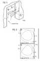
Ein weiteres Ausführungsbeispiel des erfindungsgemäßen Mikrofon-Funksystems ist in FIG 2 skizzenhaft dargestellt. Dabei zeigt die FIG eine Draufsicht auf zwei Klassenzimmer und einen Gang. In dem Klassenzimmer A befinden sich zwei Antennen 10 und 11. Diese Antennen 10 und 11 strahlen hier ebenfalls Richtkeulen 12, 13 ab. Die beiden Richtkeulen 12, 13 dienen hier dazu, das gesamte Klassenzimmer zu erfassen, bzw. abzutasten. Befindet sich ein Sendegerät 1 (in FIG 2 nicht dargestellt) in dem Klassenzimmer A und zwar innerhalb einer der Richtkeulen 12, 13, so kann er das empfangene Sendesignal dazu verwenden, sich automatisch einzuschalten.A further embodiment of the microphone radio system according to the invention is shown in sketchy form in FIG. The FIG shows a plan view of two classrooms and a corridor. In the classroom A are two
Verlässt der Lehrer mit dem Sender 1 das Klassenzimmer A und geht auf den Gang, auf dem der Sender 1 keine Funkwellen mehr empfängt, so schaltet sich der Sender 1 automatisch ab. Damit wird verhindert, dass Gespräche des Lehrers auf dem Gang von den Schülern in dem Klassenzimmer A mitgehört werden können.Leaves the teacher with the transmitter 1, the classroom A and goes to the corridor on which the transmitter 1 no more radio waves receives, the transmitter 1 turns off automatically. This prevents the teacher from hearing the conversation in the corridor from the students in classroom A.
Betritt der Lehrer nun das Klassenzimmer B, in dem sich die Antennen 20 und 21 befinden, so schaltet sich das Sendegerät des Lehrers ein, sobald es in den Erfassungsbereich der zugehörigen Richtkeulen 22 und 23 kommt. Auch hier reichen die Keulen 22 und 23 nicht auf den Gang, so dass das Sendegerät des Lehrers automatisch beim Verlassen des Klassenzimmers B abschaltet. Auch sind die Richtkeulen 12, 13 und 22, 23 in den Klassenzimmern A und B so ausgerichtet und dimensioniert, dass es, wenn möglich, keine Überlappung gibt.If the teacher now enters the classroom B in which the
Der Sender 1 des Lehrers lässt sich durch die Keulen 6, 7, 12, 13, 22, 23 nicht nur an- oder abschalten, sondern auch konfigurieren. Dies bedeutet, dass der Sender bzw. das Mikrofon-Funksystem ortsabhängig konfigurierbar ist. Insbesondere kann sich der Sender 1 des Lehrers beim Betreten des Klassenzimmers automatisch auf einen klassenzimmerspezifischen Funkkanal einstellen. In einem anderen Klassenzimmer stellt sich der Sender automatisch auf einen anderen Funkkanal ein. Auch auf diese Weise lassen sich Störungen zwischen Funksystemen zweier benachbarter Klassenzimmer vermeiden.The transmitter 1 of the teacher can not only be switched on or off by the
Wenn die zu den Antennen 4, 5, 10, 11, 20, 21 zugehörigen Sender auch in der Lage sind, ihre Sendesignale zeitlich abhängig zu variieren, so kann die Konfiguration des Funksystems beispielsweise von der Tageszeit abhängig gemacht werden. Darüber hinaus können die in den Klassenzimmern installierten Sender auch beispielsweise von den Empfängern konfiguriert werden, wenn sie entsprechende Schnittstellen besitzen.If the transmitters belonging to the
Die Konfiguration des FM-Funksystems kann sich auch auf die Empfänger 2 beziehen. Außerdem können zusätzlich Gegebenheiten bzw. Ausstattungen des Raums bei der Konfiguration der FM-Sender und / oder FM-Empfänger berücksichtigt werden. Dies ist insbesondere dann sinnvoll, wenn die Daten digital übertragen werden.The configuration of the FM radio system may also refer to the receivers 2. In addition, additional circumstances or equipment of the room in the configuration of the FM transmitter and / or FM receiver can be considered. This is particularly useful if the data is transmitted digitally.
Ist beispielsweise in einem Klassenzimmer auch ein Lautsprechersystem installiert, wird das Sprachsignal des Lehrers auch auf die Lautsprecher geschaltet. Die Funkempfänger an den Hörgeräten der Schüler können dann gegebenenfalls ausgeschaltet bleiben.For example, if a speaker system is also installed in a classroom, the teacher's voice signal will also be switched to the speakers. The radio receivers on the students' hearing aids may then remain switched off.
Auch bei diesem Ausführungsbeispiel können die Antennen 10, 11, 20, 21 Teil einer Steuervorrichtung sein, wobei die Antennen zunächst zum Detektieren eines Sendegeräts 1 und anschließend zum Senden eines entsprechenden Steuersignals an das Sendegerät 1 dienen.In this exemplary embodiment too, the
Befinden sich mehr als ein Sender im Raum, so wird das bereits beim Eintreten der jeweiligen Personen in den Raum automatisch von einem der Sendegeräte oder von der Steuervorrichtung mit Detektionseinrichtung erkannt. Der zweite hinzukommende Sender wird dann automatisch mit dem schon vorhandenen Sender gemischt. Hierzu empfängt der Sender 1 das Signal von Sender 2, addiert das Signal zu seinem eigenen hinzu und sendet es zu den Schülern. Dies bedeutet, dass zumindest der erste Sender dann auch mit einem Empfänger ausgestattet sein muss. Durch diesen Multi-Senderbetrieb können zwei oder mehr Lehrer gleichzeitig über das Funksystem zu den Schülern sprechen.If there is more than one transmitter in the room, this is automatically recognized by one of the transmitters or by the control device with detection device when the respective persons enter the room. The second incoming station is then automatically mixed with the existing station. For this purpose, the transmitter 1 receives the signal from transmitter 2, adds the signal to its own and sends it to the students. This means that at least the first transmitter must then also be equipped with a receiver. This multi-station operation allows two or more teachers to talk to the students simultaneously via the radio system.
Anstelle eines weiteren Lehrers kann beispielsweise auch eine Video- bzw. Stereoanlage als zusätzlicher Sender dienen und so in den Unterricht integriert werden. Die Schüler können dann sämtliche Quellen über ihre FM-Empfänger hören.Instead of another teacher, for example, a video or stereo system can serve as an additional transmitter and be integrated into the classroom. Students can then listen to all sources through their FM receivers.
Die Antennen 10, 11 in dem Klassenzimmer A können so platziert werden, dass eine genaue Ortsbestimmung des Senders 1 bzw. des Lehrers in dem Klassenzimmer A möglich ist. Diese zusätzlich gewonnene Ortsinformation werden gegebenenfalls dazu verwendet, von den Antennen 10, 11 ortsspezifische Steuersignale abzusenden. Mit diesen Steuersignalen kann dann der Sender 1 ortsspezifisch konfiguriert werden. Beispielsweise lässt sich so die Sendesignalamplitude des Senders 1 abhängig vom Ort in dem Veranstaltungsraum variieren. Andere ortsabhängige Konfigurationsmöglichkeiten betreffen Rauschunterdrückungsmaßnahmen und Filterungen.The
Claims (18)
Applications Claiming Priority (1)
| Application Number | Priority Date | Filing Date | Title |
|---|---|---|---|
| DE102006018155A DE102006018155A1 (en) | 2006-04-19 | 2006-04-19 | Radio transmitting device and control device for event rooms and corresponding methods |
Publications (3)
| Publication Number | Publication Date |
|---|---|
| EP1848246A2 true EP1848246A2 (en) | 2007-10-24 |
| EP1848246A3 EP1848246A3 (en) | 2010-09-08 |
| EP1848246B1 EP1848246B1 (en) | 2012-06-06 |
Family
ID=38283239
Family Applications (1)
| Application Number | Title | Priority Date | Filing Date |
|---|---|---|---|
| EP07105597A Not-in-force EP1848246B1 (en) | 2006-04-19 | 2007-04-04 | Hearing aid system comprising a radio transmitting device and method for controlling said radio transmitting device |
Country Status (3)
| Country | Link |
|---|---|
| US (2) | US8024010B2 (en) |
| EP (1) | EP1848246B1 (en) |
| DE (1) | DE102006018155A1 (en) |
Cited By (1)
| Publication number | Priority date | Publication date | Assignee | Title |
|---|---|---|---|---|
| US8933378B2 (en) | 2008-09-30 | 2015-01-13 | Siemens Aktiengesellschaft | Power supply system for a polyphase arc furnace with an indirect converter between a mains connection and a furnace transformer |
Families Citing this family (7)
| Publication number | Priority date | Publication date | Assignee | Title |
|---|---|---|---|---|
| US7778433B2 (en) * | 2005-04-29 | 2010-08-17 | Industrial Technology Research Institute | Wireless system and method thereof for hearing |
| AU2008201897B2 (en) * | 2007-04-30 | 2012-04-19 | Cochlear Limited | Bilateral Prosthesis Synchronisation |
| DE102007020595B4 (en) * | 2007-05-02 | 2009-01-02 | Siemens Ag | Device for the wireless control of an apparatus |
| DK2104378T4 (en) * | 2008-02-19 | 2017-08-28 | Starkey Labs Inc | WIRELESS SIGNAL SYSTEM TO IDENTIFY ACOUSTIC ENVIRONMENT FOR HEARING DEVICES |
| US8953810B2 (en) | 2011-03-03 | 2015-02-10 | Cochlear Limited | Synchronization in a bilateral auditory prosthesis system |
| EP2528358A1 (en) | 2011-05-23 | 2012-11-28 | Oticon A/S | A method of identifying a wireless communication channel in a sound system |
| US9532147B2 (en) | 2013-07-19 | 2016-12-27 | Starkey Laboratories, Inc. | System for detection of special environments for hearing assistance devices |
Citations (5)
| Publication number | Priority date | Publication date | Assignee | Title |
|---|---|---|---|---|
| US5734964A (en) * | 1993-10-01 | 1998-03-31 | Chaparral Communications | Mass programmable FM stereo sound equalized assistive listening apparatus |
| WO1998045963A1 (en) * | 1997-04-04 | 1998-10-15 | Etymotic Research, Inc. | System and method for enhancing speech intelligibility utilizing wireless communication |
| US20030044033A1 (en) * | 2000-01-07 | 2003-03-06 | Julstrom Stephen D. | Transmission detection and switch system for hearing improvement applications |
| EP1531650A2 (en) * | 2003-11-12 | 2005-05-18 | Gennum Corporation | Hearing instrument having a wireless base unit |
| GB2410400A (en) * | 2004-01-16 | 2005-07-27 | Abolghasem Chizari | Information delivery |
Family Cites Families (32)
| Publication number | Priority date | Publication date | Assignee | Title |
|---|---|---|---|---|
| US4700179A (en) * | 1982-04-12 | 1987-10-13 | Ici Americas Inc. | Crossed beam high frequency anti-theft system |
| US4773427A (en) * | 1987-05-26 | 1988-09-27 | Fukuda Denshi Co., Ltd. | Water-proof device for transmitter |
| US5201007A (en) * | 1988-09-15 | 1993-04-06 | Epic Corporation | Apparatus and method for conveying amplified sound to ear |
| US5241582A (en) * | 1989-11-30 | 1993-08-31 | Hyundai Electronics Industries Co., Ltd. | Control for supplying power to car audio and phone systems |
| US5276908A (en) * | 1990-10-25 | 1994-01-04 | Northern Telecom Limited | Call set-up and spectrum sharing in radio communication on systems with dynamic channel allocation |
| US5298692A (en) * | 1990-11-09 | 1994-03-29 | Kabushiki Kaisha Pilot | Earpiece for insertion in an ear canal, and an earphone, microphone, and earphone/microphone combination comprising the same |
| EP0523722B1 (en) * | 1991-07-19 | 1997-10-22 | Fujitsu Limited | Cordless telephone set |
| KR950013619B1 (en) * | 1992-11-13 | 1995-11-13 | 삼성전자주식회사 | The battery saving method in mobile phone |
| US5375123A (en) * | 1993-02-05 | 1994-12-20 | Telefonakitebolaget L. M. Ericsson | Allocation of channels using interference estimation |
| US5442934A (en) * | 1994-04-13 | 1995-08-22 | Atlantic Richfield Company | Chilled gas transmission system and method |
| CA2221364A1 (en) * | 1995-05-18 | 1996-11-21 | Aura Communications, Inc. | Short-range magnetic communication system |
| KR100429044B1 (en) * | 1995-07-03 | 2004-10-02 | 코닌클리케 필립스 일렉트로닉스 엔.브이. | Building management system with packet hopping communication |
| US5956330A (en) * | 1997-03-31 | 1999-09-21 | Resound Corporation | Bandwidth management in a heterogenous wireless personal communications system |
| JP3005496B2 (en) * | 1997-05-21 | 2000-01-31 | 日本電気株式会社 | Transmission restriction device, wireless transmission / reception terminal device, and transmission restriction system using the same |
| FI109843B (en) * | 1998-04-09 | 2002-10-15 | Ist Oy | Real estate automation control system controlled by human physiological signals |
| US6377608B1 (en) * | 1998-09-30 | 2002-04-23 | Intersil Americas Inc. | Pulsed beacon-based interference reduction mechanism for wireless communication networks |
| US6823195B1 (en) * | 2000-06-30 | 2004-11-23 | Peter V. Boesen | Ultra short range communication with sensing device and method |
| US6865276B1 (en) * | 1999-11-03 | 2005-03-08 | Telefonaktiebolaget Lm Ericsson | System and method for noise suppression in a communication signal |
| US6496703B1 (en) * | 1999-12-13 | 2002-12-17 | Lucent Technologies Inc. | System for disabling wireless communication devices |
| GB2363504A (en) * | 2000-06-16 | 2001-12-19 | Nokia Mobile Phones Ltd | A mobile phone including a device for preventing loss or theft |
| JP2002095064A (en) * | 2000-07-10 | 2002-03-29 | Rohm Co Ltd | Portable information equipment with communication function, system for controlling its portable information equipment and equipment having controller for controlling the portable information equipment |
| AU2000269773B2 (en) * | 2000-09-18 | 2006-03-02 | Phonak Ag | Method for controlling a transmission system, use of this method, transmission system, receiving unit and hearing aid |
| DE10061507C2 (en) | 2000-12-06 | 2003-04-24 | Ralf Heck | Process for current, location-based information of people through acoustic and / or optical information |
| US6788199B2 (en) * | 2001-03-12 | 2004-09-07 | Eureka Technology Partners, Llc | Article locator system |
| US6823199B2 (en) * | 2001-06-29 | 2004-11-23 | Intel Corporation | System and method for controlling a wireless device notification alert |
| US6987947B2 (en) * | 2001-10-30 | 2006-01-17 | Unwired Technology Llc | Multiple channel wireless communication system |
| US7221939B2 (en) * | 2002-08-16 | 2007-05-22 | Nokia Corporation | System, method, and apparatus for automatically selecting mobile device profiles |
| US20050272477A1 (en) * | 2004-06-07 | 2005-12-08 | Boykins Sakata E | Voice dependent recognition wireless headset universal remote control with telecommunication capabilities |
| US7183919B2 (en) * | 2004-11-05 | 2007-02-27 | Shih-Ho Wang | RFID delivery and pickup determination system |
| US20060223467A1 (en) * | 2005-04-05 | 2006-10-05 | Nokia Corporation | Method and device for low-power FM transmission of audio data to RDS (Radio Data System) capable FM radio receiver |
| US20060276130A1 (en) * | 2005-06-01 | 2006-12-07 | Shai Waxman | Device, system and method of reduced power consumption multi-receiver |
| US20080303707A1 (en) * | 2007-06-07 | 2008-12-11 | Larsen Jan Pt | Wireless remote |
-
2006
- 2006-04-19 DE DE102006018155A patent/DE102006018155A1/en not_active Withdrawn
-
2007
- 2007-04-04 EP EP07105597A patent/EP1848246B1/en not_active Not-in-force
- 2007-04-19 US US11/788,149 patent/US8024010B2/en not_active Expired - Fee Related
-
2010
- 2010-02-03 US US12/699,121 patent/US20100136930A1/en not_active Abandoned
Patent Citations (5)
| Publication number | Priority date | Publication date | Assignee | Title |
|---|---|---|---|---|
| US5734964A (en) * | 1993-10-01 | 1998-03-31 | Chaparral Communications | Mass programmable FM stereo sound equalized assistive listening apparatus |
| WO1998045963A1 (en) * | 1997-04-04 | 1998-10-15 | Etymotic Research, Inc. | System and method for enhancing speech intelligibility utilizing wireless communication |
| US20030044033A1 (en) * | 2000-01-07 | 2003-03-06 | Julstrom Stephen D. | Transmission detection and switch system for hearing improvement applications |
| EP1531650A2 (en) * | 2003-11-12 | 2005-05-18 | Gennum Corporation | Hearing instrument having a wireless base unit |
| GB2410400A (en) * | 2004-01-16 | 2005-07-27 | Abolghasem Chizari | Information delivery |
Cited By (1)
| Publication number | Priority date | Publication date | Assignee | Title |
|---|---|---|---|---|
| US8933378B2 (en) | 2008-09-30 | 2015-01-13 | Siemens Aktiengesellschaft | Power supply system for a polyphase arc furnace with an indirect converter between a mains connection and a furnace transformer |
Also Published As
| Publication number | Publication date |
|---|---|
| EP1848246A3 (en) | 2010-09-08 |
| US20100136930A1 (en) | 2010-06-03 |
| DE102006018155A1 (en) | 2007-10-25 |
| US8024010B2 (en) | 2011-09-20 |
| US20070249289A1 (en) | 2007-10-25 |
| EP1848246B1 (en) | 2012-06-06 |
Similar Documents
| Publication | Publication Date | Title |
|---|---|---|
| EP1848246B1 (en) | Hearing aid system comprising a radio transmitting device and method for controlling said radio transmitting device | |
| EP1698908B1 (en) | Method for adjusting a hearing aid, hearing aid and mobile control unit for the adjustment of a hearing aid | |
| CH695977A5 (en) | Method for operating a hearing aid device, as well as Hörhilfegeräteanordnung. | |
| DE10109359A1 (en) | Diversity antenna arrangement | |
| EP1848245B1 (en) | Hearing aid with source separation and corresponding method | |
| DE10115053A1 (en) | Method and device for suppressing multipath interference in a receiver for electromagnetic waves | |
| EP1303166B1 (en) | Method of operating a hearing aid and assembly with a hearing aid | |
| WO2014138758A2 (en) | Method for increasing the comprehensibility of speech | |
| EP3327699B1 (en) | Method for transferring voice signals | |
| DE10137404C2 (en) | Method for operating a wireless audio system with dynamic channel selection | |
| DE3210298C2 (en) | ||
| EP1865747B1 (en) | Audio system with inductive transmission and broadband transmission | |
| DE3147815C1 (en) | Radio receiving device with a filter bank receiver | |
| EP3909156B1 (en) | Operating a wireless receiver | |
| DE102009052298A1 (en) | microphone system | |
| DE102008046041A1 (en) | Hearing system, has hearing device and external unit, where test signal is released in preferred direction by transmitting antenna of hearing device and is evaluated by external unit for determining preferred direction | |
| DE3140415A1 (en) | Method for monitoring an alternate voice transmission system | |
| EP0329641B1 (en) | Receiving device for signals transmitted on the basis of the IUR standard to vehicles, especially railway vehicles | |
| DE202004014835U1 (en) | Monitoring device for babies/baby phone has radio equipment for monitoring/watching a person and an area with a noise transmitter and a signal receiver | |
| DE102005051125A1 (en) | Object location procedure fits them with mobile transmit receivers and uses fixed radio stations transmitting location signal request to determine occupied zones | |
| DE202014100360U1 (en) | Ultrasonic wave data transmission system | |
| DE202016105832U1 (en) | Ambient detection device | |
| DE10135059A1 (en) | Communications system has central unit connected to loudspeaker and microphone unit(s) worn by person , selectable channels for communications signal reception and/or transmission | |
| DE10316170A1 (en) | monitoring device | |
| DE1923261A1 (en) | Language laboratory system |
Legal Events
| Date | Code | Title | Description |
|---|---|---|---|
| PUAI | Public reference made under article 153(3) epc to a published international application that has entered the european phase |
Free format text: ORIGINAL CODE: 0009012 |
|
| AK | Designated contracting states |
Kind code of ref document: A2 Designated state(s): AT BE BG CH CY CZ DE DK EE ES FI FR GB GR HU IE IS IT LI LT LU LV MC MT NL PL PT RO SE SI SK TR |
|
| AX | Request for extension of the european patent |
Extension state: AL BA HR MK YU |
|
| PUAL | Search report despatched |
Free format text: ORIGINAL CODE: 0009013 |
|
| AK | Designated contracting states |
Kind code of ref document: A3 Designated state(s): AT BE BG CH CY CZ DE DK EE ES FI FR GB GR HU IE IS IT LI LT LU LV MC MT NL PL PT RO SE SI SK TR |
|
| AX | Request for extension of the european patent |
Extension state: AL BA HR MK RS |
|
| RIC1 | Information provided on ipc code assigned before grant |
Ipc: H04B 7/005 20060101ALN20100804BHEP Ipc: G09B 5/04 20060101ALI20100804BHEP Ipc: G09B 21/04 20060101ALI20100804BHEP Ipc: G09B 21/00 20060101ALI20100804BHEP Ipc: H04R 25/00 20060101ALI20100804BHEP Ipc: H04R 27/02 20060101AFI20100804BHEP |
|
| 17P | Request for examination filed |
Effective date: 20101220 |
|
| AKX | Designation fees paid |
Designated state(s): AT BE BG CH CY CZ DE DK EE ES FI FR GB GR HU IE IS IT LI LT LU LV MC MT NL PL PT RO SE SI SK TR |
|
| REG | Reference to a national code |
Ref country code: DE Ref legal event code: R079 Ref document number: 502007009988 Country of ref document: DE Free format text: PREVIOUS MAIN CLASS: H04R0027000000 Ipc: H04R0027020000 |
|
| GRAP | Despatch of communication of intention to grant a patent |
Free format text: ORIGINAL CODE: EPIDOSNIGR1 |
|
| RIC1 | Information provided on ipc code assigned before grant |
Ipc: G09B 5/04 20060101ALI20111115BHEP Ipc: G09B 21/00 20060101ALI20111115BHEP Ipc: H04B 7/005 20060101ALN20111115BHEP Ipc: G09B 21/04 20060101ALI20111115BHEP Ipc: H04R 27/02 20060101AFI20111115BHEP Ipc: H04R 25/00 20060101ALI20111115BHEP |
|
| RTI1 | Title (correction) |
Free format text: HEARING AID SYSTEM COMPRISING A RADIO TRANSMITTING DEVICE AND METHOD FOR CONTROLLING SAID RADIO TRANSMITTING DEVICE |
|
| RIC1 | Information provided on ipc code assigned before grant |
Ipc: G09B 5/04 20060101ALI20111122BHEP Ipc: G09B 21/04 20060101ALI20111122BHEP Ipc: G09B 21/00 20060101ALI20111122BHEP Ipc: H04B 7/005 20060101ALN20111122BHEP Ipc: H04R 25/00 20060101ALI20111122BHEP Ipc: H04R 27/02 20060101AFI20111122BHEP |
|
| RIC1 | Information provided on ipc code assigned before grant |
Ipc: H04R 25/00 20060101ALI20111125BHEP Ipc: H04R 27/02 20060101AFI20111125BHEP Ipc: H04B 7/005 20060101ALN20111125BHEP Ipc: G09B 21/00 20060101ALI20111125BHEP Ipc: G09B 21/04 20060101ALI20111125BHEP Ipc: G09B 5/04 20060101ALI20111125BHEP |
|
| GRAS | Grant fee paid |
Free format text: ORIGINAL CODE: EPIDOSNIGR3 |
|
| GRAA | (expected) grant |
Free format text: ORIGINAL CODE: 0009210 |
|
| AK | Designated contracting states |
Kind code of ref document: B1 Designated state(s): AT BE BG CH CY CZ DE DK EE ES FI FR GB GR HU IE IS IT LI LT LU LV MC MT NL PL PT RO SE SI SK TR |
|
| REG | Reference to a national code |
Ref country code: GB Ref legal event code: FG4D Free format text: NOT ENGLISH |
|
| REG | Reference to a national code |
Ref country code: CH Ref legal event code: NV Representative=s name: SIEMENS SCHWEIZ AG Ref country code: CH Ref legal event code: EP Ref country code: AT Ref legal event code: REF Ref document number: 561502 Country of ref document: AT Kind code of ref document: T Effective date: 20120615 |
|
| REG | Reference to a national code |
Ref country code: IE Ref legal event code: FG4D Free format text: LANGUAGE OF EP DOCUMENT: GERMAN |
|
| REG | Reference to a national code |
Ref country code: DE Ref legal event code: R096 Ref document number: 502007009988 Country of ref document: DE Effective date: 20120802 |
|
| REG | Reference to a national code |
Ref country code: NL Ref legal event code: VDEP Effective date: 20120606 |
|
| PG25 | Lapsed in a contracting state [announced via postgrant information from national office to epo] |
Ref country code: CY Free format text: LAPSE BECAUSE OF FAILURE TO SUBMIT A TRANSLATION OF THE DESCRIPTION OR TO PAY THE FEE WITHIN THE PRESCRIBED TIME-LIMIT Effective date: 20120606 Ref country code: SE Free format text: LAPSE BECAUSE OF FAILURE TO SUBMIT A TRANSLATION OF THE DESCRIPTION OR TO PAY THE FEE WITHIN THE PRESCRIBED TIME-LIMIT Effective date: 20120606 Ref country code: LT Free format text: LAPSE BECAUSE OF FAILURE TO SUBMIT A TRANSLATION OF THE DESCRIPTION OR TO PAY THE FEE WITHIN THE PRESCRIBED TIME-LIMIT Effective date: 20120606 Ref country code: FI Free format text: LAPSE BECAUSE OF FAILURE TO SUBMIT A TRANSLATION OF THE DESCRIPTION OR TO PAY THE FEE WITHIN THE PRESCRIBED TIME-LIMIT Effective date: 20120606 |
|
| REG | Reference to a national code |
Ref country code: LT Ref legal event code: MG4D Effective date: 20120606 |
|
| PG25 | Lapsed in a contracting state [announced via postgrant information from national office to epo] |
Ref country code: GR Free format text: LAPSE BECAUSE OF FAILURE TO SUBMIT A TRANSLATION OF THE DESCRIPTION OR TO PAY THE FEE WITHIN THE PRESCRIBED TIME-LIMIT Effective date: 20120907 Ref country code: SI Free format text: LAPSE BECAUSE OF FAILURE TO SUBMIT A TRANSLATION OF THE DESCRIPTION OR TO PAY THE FEE WITHIN THE PRESCRIBED TIME-LIMIT Effective date: 20120606 Ref country code: LV Free format text: LAPSE BECAUSE OF FAILURE TO SUBMIT A TRANSLATION OF THE DESCRIPTION OR TO PAY THE FEE WITHIN THE PRESCRIBED TIME-LIMIT Effective date: 20120606 |
|
| PG25 | Lapsed in a contracting state [announced via postgrant information from national office to epo] |
Ref country code: CZ Free format text: LAPSE BECAUSE OF FAILURE TO SUBMIT A TRANSLATION OF THE DESCRIPTION OR TO PAY THE FEE WITHIN THE PRESCRIBED TIME-LIMIT Effective date: 20120606 Ref country code: SK Free format text: LAPSE BECAUSE OF FAILURE TO SUBMIT A TRANSLATION OF THE DESCRIPTION OR TO PAY THE FEE WITHIN THE PRESCRIBED TIME-LIMIT Effective date: 20120606 Ref country code: NL Free format text: LAPSE BECAUSE OF FAILURE TO SUBMIT A TRANSLATION OF THE DESCRIPTION OR TO PAY THE FEE WITHIN THE PRESCRIBED TIME-LIMIT Effective date: 20120606 Ref country code: IS Free format text: LAPSE BECAUSE OF FAILURE TO SUBMIT A TRANSLATION OF THE DESCRIPTION OR TO PAY THE FEE WITHIN THE PRESCRIBED TIME-LIMIT Effective date: 20121006 Ref country code: RO Free format text: LAPSE BECAUSE OF FAILURE TO SUBMIT A TRANSLATION OF THE DESCRIPTION OR TO PAY THE FEE WITHIN THE PRESCRIBED TIME-LIMIT Effective date: 20120606 Ref country code: EE Free format text: LAPSE BECAUSE OF FAILURE TO SUBMIT A TRANSLATION OF THE DESCRIPTION OR TO PAY THE FEE WITHIN THE PRESCRIBED TIME-LIMIT Effective date: 20120606 |
|
| PG25 | Lapsed in a contracting state [announced via postgrant information from national office to epo] |
Ref country code: PT Free format text: LAPSE BECAUSE OF FAILURE TO SUBMIT A TRANSLATION OF THE DESCRIPTION OR TO PAY THE FEE WITHIN THE PRESCRIBED TIME-LIMIT Effective date: 20121008 Ref country code: IT Free format text: LAPSE BECAUSE OF FAILURE TO SUBMIT A TRANSLATION OF THE DESCRIPTION OR TO PAY THE FEE WITHIN THE PRESCRIBED TIME-LIMIT Effective date: 20120606 Ref country code: PL Free format text: LAPSE BECAUSE OF FAILURE TO SUBMIT A TRANSLATION OF THE DESCRIPTION OR TO PAY THE FEE WITHIN THE PRESCRIBED TIME-LIMIT Effective date: 20120606 |
|
| PLBE | No opposition filed within time limit |
Free format text: ORIGINAL CODE: 0009261 |
|
| STAA | Information on the status of an ep patent application or granted ep patent |
Free format text: STATUS: NO OPPOSITION FILED WITHIN TIME LIMIT |
|
| PG25 | Lapsed in a contracting state [announced via postgrant information from national office to epo] |
Ref country code: DK Free format text: LAPSE BECAUSE OF FAILURE TO SUBMIT A TRANSLATION OF THE DESCRIPTION OR TO PAY THE FEE WITHIN THE PRESCRIBED TIME-LIMIT Effective date: 20120606 Ref country code: ES Free format text: LAPSE BECAUSE OF FAILURE TO SUBMIT A TRANSLATION OF THE DESCRIPTION OR TO PAY THE FEE WITHIN THE PRESCRIBED TIME-LIMIT Effective date: 20120917 |
|
| 26N | No opposition filed |
Effective date: 20130307 |
|
| REG | Reference to a national code |
Ref country code: DE Ref legal event code: R097 Ref document number: 502007009988 Country of ref document: DE Effective date: 20130307 |
|
| PG25 | Lapsed in a contracting state [announced via postgrant information from national office to epo] |
Ref country code: BG Free format text: LAPSE BECAUSE OF FAILURE TO SUBMIT A TRANSLATION OF THE DESCRIPTION OR TO PAY THE FEE WITHIN THE PRESCRIBED TIME-LIMIT Effective date: 20120906 |
|
| BERE | Be: lapsed |
Owner name: SIEMENS AUDIOLOGISCHE TECHNIK G.M.B.H. Effective date: 20130430 |
|
| PG25 | Lapsed in a contracting state [announced via postgrant information from national office to epo] |
Ref country code: MC Free format text: LAPSE BECAUSE OF FAILURE TO SUBMIT A TRANSLATION OF THE DESCRIPTION OR TO PAY THE FEE WITHIN THE PRESCRIBED TIME-LIMIT Effective date: 20120606 |
|
| REG | Reference to a national code |
Ref country code: CH Ref legal event code: PL |
|
| GBPC | Gb: european patent ceased through non-payment of renewal fee |
Effective date: 20130404 |
|
| REG | Reference to a national code |
Ref country code: IE Ref legal event code: MM4A |
|
| PG25 | Lapsed in a contracting state [announced via postgrant information from national office to epo] |
Ref country code: BE Free format text: LAPSE BECAUSE OF NON-PAYMENT OF DUE FEES Effective date: 20130430 Ref country code: CH Free format text: LAPSE BECAUSE OF NON-PAYMENT OF DUE FEES Effective date: 20130430 Ref country code: LI Free format text: LAPSE BECAUSE OF NON-PAYMENT OF DUE FEES Effective date: 20130430 Ref country code: GB Free format text: LAPSE BECAUSE OF NON-PAYMENT OF DUE FEES Effective date: 20130404 Ref country code: DE Free format text: LAPSE BECAUSE OF NON-PAYMENT OF DUE FEES Effective date: 20131101 |
|
| REG | Reference to a national code |
Ref country code: FR Ref legal event code: ST Effective date: 20131231 |
|
| REG | Reference to a national code |
Ref country code: DE Ref legal event code: R119 Ref document number: 502007009988 Country of ref document: DE Effective date: 20131101 |
|
| PG25 | Lapsed in a contracting state [announced via postgrant information from national office to epo] |
Ref country code: FR Free format text: LAPSE BECAUSE OF NON-PAYMENT OF DUE FEES Effective date: 20130430 |
|
| PG25 | Lapsed in a contracting state [announced via postgrant information from national office to epo] |
Ref country code: IE Free format text: LAPSE BECAUSE OF NON-PAYMENT OF DUE FEES Effective date: 20130404 |
|
| REG | Reference to a national code |
Ref country code: AT Ref legal event code: MM01 Ref document number: 561502 Country of ref document: AT Kind code of ref document: T Effective date: 20130404 |
|
| PG25 | Lapsed in a contracting state [announced via postgrant information from national office to epo] |
Ref country code: AT Free format text: LAPSE BECAUSE OF NON-PAYMENT OF DUE FEES Effective date: 20130404 |
|
| PG25 | Lapsed in a contracting state [announced via postgrant information from national office to epo] |
Ref country code: MT Free format text: LAPSE BECAUSE OF FAILURE TO SUBMIT A TRANSLATION OF THE DESCRIPTION OR TO PAY THE FEE WITHIN THE PRESCRIBED TIME-LIMIT Effective date: 20120606 |
|
| PG25 | Lapsed in a contracting state [announced via postgrant information from national office to epo] |
Ref country code: TR Free format text: LAPSE BECAUSE OF FAILURE TO SUBMIT A TRANSLATION OF THE DESCRIPTION OR TO PAY THE FEE WITHIN THE PRESCRIBED TIME-LIMIT Effective date: 20120606 |
|
| PG25 | Lapsed in a contracting state [announced via postgrant information from national office to epo] |
Ref country code: HU Free format text: LAPSE BECAUSE OF FAILURE TO SUBMIT A TRANSLATION OF THE DESCRIPTION OR TO PAY THE FEE WITHIN THE PRESCRIBED TIME-LIMIT; INVALID AB INITIO Effective date: 20070404 Ref country code: LU Free format text: LAPSE BECAUSE OF NON-PAYMENT OF DUE FEES Effective date: 20130404 |