EP1847429A1 - Vehicle braking system - Google Patents
Vehicle braking system Download PDFInfo
- Publication number
- EP1847429A1 EP1847429A1 EP06008206A EP06008206A EP1847429A1 EP 1847429 A1 EP1847429 A1 EP 1847429A1 EP 06008206 A EP06008206 A EP 06008206A EP 06008206 A EP06008206 A EP 06008206A EP 1847429 A1 EP1847429 A1 EP 1847429A1
- Authority
- EP
- European Patent Office
- Prior art keywords
- brake
- vehicle
- brake lever
- control unit
- lever
- Prior art date
- Legal status (The legal status is an assumption and is not a legal conclusion. Google has not performed a legal analysis and makes no representation as to the accuracy of the status listed.)
- Granted
Links
Images


Classifications
-
- B—PERFORMING OPERATIONS; TRANSPORTING
- B60—VEHICLES IN GENERAL
- B60T—VEHICLE BRAKE CONTROL SYSTEMS OR PARTS THEREOF; BRAKE CONTROL SYSTEMS OR PARTS THEREOF, IN GENERAL; ARRANGEMENT OF BRAKING ELEMENTS ON VEHICLES IN GENERAL; PORTABLE DEVICES FOR PREVENTING UNWANTED MOVEMENT OF VEHICLES; VEHICLE MODIFICATIONS TO FACILITATE COOLING OF BRAKES
- B60T8/00—Arrangements for adjusting wheel-braking force to meet varying vehicular or ground-surface conditions, e.g. limiting or varying distribution of braking force
- B60T8/17—Using electrical or electronic regulation means to control braking
- B60T8/1701—Braking or traction control means specially adapted for particular types of vehicles
- B60T8/1706—Braking or traction control means specially adapted for particular types of vehicles for single-track vehicles, e.g. motorcycles
-
- B—PERFORMING OPERATIONS; TRANSPORTING
- B60—VEHICLES IN GENERAL
- B60T—VEHICLE BRAKE CONTROL SYSTEMS OR PARTS THEREOF; BRAKE CONTROL SYSTEMS OR PARTS THEREOF, IN GENERAL; ARRANGEMENT OF BRAKING ELEMENTS ON VEHICLES IN GENERAL; PORTABLE DEVICES FOR PREVENTING UNWANTED MOVEMENT OF VEHICLES; VEHICLE MODIFICATIONS TO FACILITATE COOLING OF BRAKES
- B60T8/00—Arrangements for adjusting wheel-braking force to meet varying vehicular or ground-surface conditions, e.g. limiting or varying distribution of braking force
- B60T8/17—Using electrical or electronic regulation means to control braking
- B60T8/1755—Brake regulation specially adapted to control the stability of the vehicle, e.g. taking into account yaw rate or transverse acceleration in a curve
-
- B—PERFORMING OPERATIONS; TRANSPORTING
- B60—VEHICLES IN GENERAL
- B60T—VEHICLE BRAKE CONTROL SYSTEMS OR PARTS THEREOF; BRAKE CONTROL SYSTEMS OR PARTS THEREOF, IN GENERAL; ARRANGEMENT OF BRAKING ELEMENTS ON VEHICLES IN GENERAL; PORTABLE DEVICES FOR PREVENTING UNWANTED MOVEMENT OF VEHICLES; VEHICLE MODIFICATIONS TO FACILITATE COOLING OF BRAKES
- B60T8/00—Arrangements for adjusting wheel-braking force to meet varying vehicular or ground-surface conditions, e.g. limiting or varying distribution of braking force
- B60T8/32—Arrangements for adjusting wheel-braking force to meet varying vehicular or ground-surface conditions, e.g. limiting or varying distribution of braking force responsive to a speed condition, e.g. acceleration or deceleration
- B60T8/321—Arrangements for adjusting wheel-braking force to meet varying vehicular or ground-surface conditions, e.g. limiting or varying distribution of braking force responsive to a speed condition, e.g. acceleration or deceleration deceleration
- B60T8/3225—Systems specially adapted for single-track vehicles, e.g. motorcycles
-
- B—PERFORMING OPERATIONS; TRANSPORTING
- B60—VEHICLES IN GENERAL
- B60T—VEHICLE BRAKE CONTROL SYSTEMS OR PARTS THEREOF; BRAKE CONTROL SYSTEMS OR PARTS THEREOF, IN GENERAL; ARRANGEMENT OF BRAKING ELEMENTS ON VEHICLES IN GENERAL; PORTABLE DEVICES FOR PREVENTING UNWANTED MOVEMENT OF VEHICLES; VEHICLE MODIFICATIONS TO FACILITATE COOLING OF BRAKES
- B60T8/00—Arrangements for adjusting wheel-braking force to meet varying vehicular or ground-surface conditions, e.g. limiting or varying distribution of braking force
- B60T8/32—Arrangements for adjusting wheel-braking force to meet varying vehicular or ground-surface conditions, e.g. limiting or varying distribution of braking force responsive to a speed condition, e.g. acceleration or deceleration
- B60T8/34—Arrangements for adjusting wheel-braking force to meet varying vehicular or ground-surface conditions, e.g. limiting or varying distribution of braking force responsive to a speed condition, e.g. acceleration or deceleration having a fluid pressure regulator responsive to a speed condition
- B60T8/48—Arrangements for adjusting wheel-braking force to meet varying vehicular or ground-surface conditions, e.g. limiting or varying distribution of braking force responsive to a speed condition, e.g. acceleration or deceleration having a fluid pressure regulator responsive to a speed condition connecting the brake actuator to an alternative or additional source of fluid pressure, e.g. traction control systems
- B60T8/4809—Traction control, stability control, using both the wheel brakes and other automatic braking systems
Definitions
- the present invention relates to straddle-type wheeled vehicle braking systems.
- Three-wheeled vehicles are well known in the art. Such vehicles are typically off-road type or all-terrain vehicles (also known as "ATVs"). Two different configurations of three-wheeled vehicles are generally known. The first configuration has one wheel at the front and two wheels at the back of the vehicle. The second configuration has two wheels at the front and one wheel at the back.
- three-wheeled vehicles are intrinsically less stable than four-wheeled vehicles, such as automobiles.
- Several factors contribute to this instability.
- the rollover axes of the three-wheeled vehicle are closer to the CG than they are for a four-wheeled vehicle.
- the center of gravity of a vehicle is measured as a distance from the ground when the vehicle is at rest.
- the center of gravity changes based on the rider position and the type of seating arrangement provided.
- a straddle seat type vehicle positions the rider higher from the ground and, as a result, typically creates a vehicle with a higher center of gravity than a vehicle that has a recumbent type seat, which may be more stable but requires additional space and have a different weight distribution since the rider cannot be superposed over the engine.
- Recumbent seat configurations generally position two riders side by side.
- straddle seats may alter disadvantageously the center of gravity of a vehicle, they offer certain advantages that are not available with recumbent seats.
- straddle seats allow a more compact riding position, allow a better vision since the driver is higher, make the rider more visible, and permit the rider to lean into a turn for enhanced handling.
- Straddle seats also may provide a second passenger seat behind the driver seat, if desired, but the additional rider also tends to raise the center of gravity of the vehicle.
- An advantage of a tandem straddle-type vehicle is that the center of gravity of the vehicle remains laterally symmetrically positioned if there are one or more riders.
- the center of gravity is not located in the same lateral position as when there are two riders in the vehicle.
- the center of gravity will be offset from the longitudinal centerline of the vehicle in a direction towards the driver. As would be appreciated by those skilled in the art, this offset may have an effect on the handling performance of the recumbent-seated vehicle.
- the wheel base refers to the distance between the front tire(s) and the rear tire(s).
- the wheel track refers to the distance between two tires on the same axle. A larger distance between the tires (whether it be the wheel base or the wheel track) enhances the stability of the vehicle, but creates a larger vehicle, in terms of overall length and/or width (as the case may be), which may be less maneuverable because of the vehicle's increased size.
- Three-wheeled vehicles raise special stability concerns since there is a smaller total tire contact area with the ground as compared with similarly sized four-wheeled vehicles.
- three-wheeled vehicles have a smaller weight and therefore they are more sensitive to variations in loading, particularly driver, passenger and cargo weight.
- the center of gravity can be relatively high as compared with that of a recumbent three-wheeled vehicle.
- road tires To equip a three-wheeled vehicle for road use, road tires must be employed. At high speeds or in sharp turns, the centrifugal forces generated on a road may, under certain conditions, exceed the traction threshold of a road tire, which could cause one or more of the tires to slip on the road surface. The slippage may be so severe that the vehicle could oversteer or understeer under certain circumstances.
- modem road tires can offer considerable grip on a road surface.
- the gripping force of modem road tires can be so strong, in fact, that a vehicle with a high center of gravity may, under certain conditions, be subjected to forces that may cause the vehicle to exceed its wheel lift threshold. If the wheel lift threshold is exceeded, one or more of the vehicle's wheels on the inner side of the curve may lift off of the road surface. Under such circumstances, if the rider continues to apply a lateral acceleration to the vehicle, the vehicle may rollover. Tripped rollover can also be experienced under severe oversteering conditions if the tires suddenly recover traction with the ground or hit an obstacle side ways.
- Electronic stability systems also known as vehicle stability systems (VSS) are designed to electronically manage different systems on an automotive vehicle to influence and control the vehicle's behavior.
- An ESS can manage a considerable number of parameters at the same time. This provides an advantage over an automotive vehicle merely operated by a person since the driver can only manage a limited number of parameters at the same time.
- a typical ESS takes several inputs from the vehicle and applies different outputs to the vehicle to influence the vehicle's behavior. Examples of inputs include steering column rotation, the longitudinal and transverse acceleration of the vehicle, the engine output, the detection of the presence (or absence) of a rider and a passenger, the speed of the four wheels, the brake pressure in the wheel's brakes, the yaw rate, and the yaw rate angle.
- Traditional ESSs use inputs from all four wheels (on a four wheel vehicle). Some low-cost systems use reduced inputs, but this does not result in optimal behavior interpretation. Inputs from suspension displacement, brake and accelerator pedals displacement can also be provided to the ESS.
- the outputs from the ESS affect an automobile's behavior by generally independently managing the brakes on each wheel, the suspension, and the power output of the engine in order to improve the automobile's handling under certain circumstances. Since ESSs have been specifically developed for four-wheeled vehicles and rely on inputs provided by a four-wheeled vehicle, it is time consuming to adapt this kind of system to a three-wheeled vehicle. This is especially true since an ESS typically uses inputs from each of the four wheels independently and uses the braking system independently on all of the wheels.
- a three-wheeled vehicle configured with a single wheel at one end of the vehicle does not provide all the information/data input required by a four-wheeled vehicle ESS.
- a four-wheeled vehicle ESS For example in a two front wheels, one rear wheel configuration, there is only one rear wheel from which the ESS can receive input on speed.
- a yaw moment is generated about a vertical axis passing through the center of gravity of the vehicle.
- the rear wheel is positioned in the same plane as the longitudinal axis of the vehicle, which makes it difficult to generate any significant yaw moment by applying the brake to the rear wheel.
- a three-wheeled vehicle is illustrated in United States published patent publication US 2004/0035624 A1 .
- This vehicle has a straddle type seat, two front wheels, and one rear wheel.
- a foot brake pedal is used to control the braking of both the front wheels and the rear wheel, but, according to the description, preferably only the braking of the rear wheel.
- a hand brake lever is provided to control the braking of both the front wheels and the rear wheel.
- the hand brake always applies the same amount of braking to the two front wheels, which may cause the vehicle to become unstable under certain conditions.
- the driver since the driver is responsible for maintaining the stability of vehicle, the vehicle may become unstable beyond the wheel lift threshold before the driver reacts to the instability.
- actuating the foot brake pedal would not apply a braking force capable of correcting an instability of the vehicle since it would not create a significant yaw moment.
- One aspect of the invention provides a straddle-type three-wheeled vehicle having a first brake lever, a second brake lever, a master cylinder, and an electronic brake control unit for actuating the brakes of the vehicle.
- a straddle-type wheeled vehicle having a frame, a straddle seat mounted to the frame, a first wheel mounted to the frame near a first end thereof, a second wheel mounted to the frame near a second end thereof, a steering assembly mounted to the frame forwardly of the straddle seat for steering at least one of the wheels, an engine mounted to the frame for providing power to at least one of the wheels, a first brake for braking the first wheel, a second brake for braking the second wheel, a first hydraulic brake actuator, a first brake lever for actuating the first hydraulic brake actuator, a second hydraulic brake actuator, and a second brake lever for actuating the second hydraulic brake actuator.
- the vehicle is characterized in that it also has an electronic brake control unit in operative communication with the first brake and in separate operative communication with the second brake, and a sensor for sensing an operating condition of the vehicle and in operative connection with the electronic brake control unit for sending an operating condition signal to the electronic brake control unit.
- the first hydraulic brake actuator hydraulically communicates with the electronic brake control unit.
- the second hydraulic brake actuator hydraulically communicates with the electronic brake control unit.
- the first hydraulic brake actuator hydraulically actuates the first brake through the electronic brake control unit in response to actuation of the first brake lever.
- the second hydraulic brake actuator hydraulically actuates the second brake through the electronic brake control unit in response to actuation of the second brake lever.
- the electronic brake control unit selectively actuates the first and second brakes in response to the operating condition signal independently of actuation of first and second hydraulic brake actuators.
- brake lever refers to the device through which a driver of the vehicle applies braking, such as, for example, a hand or foot brake lever, a handle, or a brake pedal.
- a "hand brake lever” is a brake lever that is normally actuated by a driver's hand.
- a “foot brake lever” is a brake lever that is normally actuated by a driver's foot.
- Embodiments of the present invention each have at least one of the above-mentioned aspects, but do not necessarily have all of them.
- Fig. 1 is a perspective view, taken from a rear, left side, of a vehicle in accordance with the present invention
- Fig. 2 is a top view of the vehicle of Fig. 1;
- Fig. 3 is front view of the vehicle of Fig. 1;
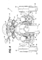
- Fig. 4 is a back view of the vehicle of Fig. 1;
- Fig. 5 is a left side elevation view of the vehicle of Fig. 1;
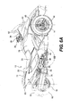
- Fig. 6A is a right side elevation view of the vehicle of Fig. 1;
- Fig. 6B is a close-up view of the section identified in Fig. 6A;
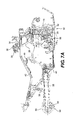
- Fig. 7A is a right side elevation view of a frame of the vehicle of Fig. 1 with the steering and braking components attached thereto;
- Fig. 7B is a close-up view of the section identified in Fig. 7A;
- Fig. 8 is a schematic force diagram of the vehicle of Fig. 1 with a braking force applied to the front left wheel;
- Fig. 9 is a schematic force diagram of the vehicle of Fig. 1 with a braking force applied to the front right wheel;
- Fig. 10 is a schematic force diagram of the vehicle of Fig. 1 with a braking force applied to the rear wheel;
- Fig. 11 is a schematic force diagram of the vehicle of Fig. 1 with a braking force applied to counteract the effects of a left turn on the vehicle;
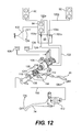
- Fig. 12 is a schematic representation of a first embodiment of a braking system to be used with the vehicle of Fig. 1;
- Fig. 13 is a schematic representation of a second embodiment of a braking system to be used with the vehicle of Fig. 1;
- Fig. 14 is a schematic representation of a third embodiment of a braking system to be used with the vehicle of Fig. 1.
- the present invention will be described herein with respect to a vehicle 10 in having a straddle seat 12, two front wheels 14, and one rear wheel 16, as illustrated in Figs. 1 to 6A. However, it is contemplated that the vehicle 10 could also have one front wheel and two rear wheels. It is also contemplated that some aspects of the present invention could be used in straddle-type vehicles having other wheel configurations.
- the vehicle 10 has a straddle seat 12 located at least partially rearwardly of a center of the vehicle 10 and disposed along the longitudinal centerline 18 (Fig. 2) thereof.
- the straddle seat 12 has a first portion 20 for accommodating a driver, and a second portion 22 for accommodating a passenger behind the driver.
- the second portion 22 is higher than the first portion 20 to permit the passenger to see in front of the vehicle 10 over the driver.
- a pair of handles 24 are provided on either sides of the second portion 22 for the passenger to hold onto. It is contemplated that the straddle seat 12 could be disposed at a different longitudinal location depending on the particular ergonomics of the vehicle 10. It is also contemplated that the straddle seat 12 could only have the first portion 20.
- a steering assembly is disposed forwardly of the straddle seat 12 to allow a driver to steer the two front wheels 14.
- the steering assembly has handlebars 26 connected to a steering column 28 (Fig. 7A).
- the steering column 28 is connected to the two front wheels 14 via a steering linkage (not shown), such that turning the handlebars 26 turns the steering column 28 which, through the steering linkage, turns the wheels 14.
- the steering assembly can optionally be provided with a power steering unit 29 (Fig. 7A) which facilitates steering of the vehicle 10.
- the handlebars 26 are provided with handles 30 for the driver to hold.
- the right handle 30 can twist and acts as the throttle controller for the engine 32 (shown schematically and in phantom in Fig. 5).
- the throttle could also be controlled by a separate lever disposed near one of the handles 30.
- a brake lever in the form of a hand brake lever 34, is provided near the right handle 30 for braking the vehicle 10, as will be explained in greater details below.
- the hand brake lever 34 is provided generally forwardly of the right handle 30 so as to be actuated by multiple fingers of a user, however, it is contemplated that the hand brake lever 34 could be provided generally forwardly of the left handle 30.
- Other types of brake levers commonly known to those skilled in the art are also contemplated.
- a pair of driver foot pegs 36 are provided on either sides of the vehicle 10 below the first portion 20 of the straddle seat 12 for a driver to rest his feet thereon.
- a pair of passenger foot pegs 38 are provided on either sides of the vehicle 10 below the second portion 22 of the straddle seat 12 for a passenger to rest his feet thereon.
- Another brake lever, in the form of a foot brake lever 40 is provided on a right side of the vehicle 10 below the first portion 20 of the straddle seat 12 for braking the vehicle 10, as will be explained in greater details below. As best seen in Fig.
- the foot brake lever 40 is preferably provided near the right driver foot peg 36 such that the driver can actuate the foot brake lever 40 while a portion of his foot remains on the right driver foot peg 36.
- the foot brake lever 40 also preferably pivots about an axis which is coaxial with the right driver foot peg 36 in order to facilitate actuation of the foot brake lever 40 by the driver.
- Each of the two front wheels 14 is mounted to the frame 42 (Fig. 7A) of the vehicle 10 via a suspension assembly 44.
- the suspension assembly 44 is preferably a double A-arm suspension, as best shown in Figs. 2 and 3, but it is contemplated that other types of suspensions could be used, such as a McPherson suspension.
- the front wheels 14 are steered via a steering assembly.
- Each of the two front wheels 14 has a tire 46 thereon which is suitable for road use.
- the tires 46 are preferably inflated to a pressure between 138 kPa and 345 kPa.
- a fairing 48 is disposed over each tire 46 to protect the driver from dirt and water which can be lifted by the tire 46 while it is rolling.
- Each of the two front wheels 14 is also provided with a brake 50.
- the brake 50 is preferably a disc brake mounted onto a wheel hub of each wheel 14, however other types of brakes are contemplated.
- the brakes 50 each have a rotor 52 mounted onto the wheel hub and a stationary caliper 54 straddling the rotor 52.
- the brake pads (not shown) are mounted to the caliper 54 so as to be disposed between the rotor 52 and the caliper 54 on either sides of the rotor 52.
- the brake pads squeeze the rotor 52 which, through friction, brakes the wheel 14.
- the rear wheel 16 is mounted to the frame 42 via a swing arm 56.
- the swing arm 56 preferably has two arms pivotally mounted at a front thereof to the frame 42 and between which the rear wheel 16 is rotatably mounted at the rear of the two arms.
- a shock absorber 58 is disposed between the swing arm 56 and the frame 42.
- the rear wheel 16 has a tire 60 thereon which is suitable for road use.
- the tire 60 is wider than the tires 46. It is contemplated that the tire 60 could have a smaller width or the same width as the tires 46. It is also contemplated that the rear wheel 16 could have two or more tires disposed next to each other thereon.
- the tire 60 is preferably inflated to a pressure between 138 kPa and 345 kPa.
- a fairing 62 is disposed over the tire 60 to protect the driver from dirt and water which can be lifted by the tire 60 while it is rolling.
- the rear wheel 16 is provided with a brake 64.
- the brake 64 is preferably a disc brake mounted to a right side of wheel 16, however other types of brakes are contemplated.
- the brake 64 has a rotor 66, caliper 68, brake pads (not shown), and a piston (not shown) similar to those used with brakes 50.
- the brake 64 brakes the rear wheel 16 in the same way as the brakes 50 brake the front wheels 14.
- a wheel sprocket 70 is mounted to a left side of the rear wheel 16.
- a belt 72 is disposed about the wheel sprocket 70 and an engine sprocket (not shown) to transmit power from the engine 32 to the rear wheel 16.
- the engine sprocket is disposed about the output shaft 74 (shown schematically in Fig. 5) of the engine 32.
- the output shaft 74 extends horizontally and perpendicularly to the longitudinal centerline 18 of the vehicle 10. It is contemplated that a continuously variable transmission (CVT) could be provided between the output shaft 74 and the engine sprocket.
- CVT continuously variable transmission
- a vehicle body 78 is attached to the frame 42 in order to protect the components mounted to the frame 42 from the elements and to make the vehicle 10 aesthetically pleasing.
- a clockwise yaw moment Y v about the center of mass C which induces either an oversteer or an understeer condition can be counteracted by a braking force applied to the front left tire 14 to create a force vector b .
- the braking force b generates a counter-clockwise braking yaw moment Y b to counteract the vehicle's yaw moment Y v .
- a counter-clockwise yaw moment Y v inducing either an oversteer or an understeer condition can be counteracted by a braking force applied to the front right tire 14 to create a force vector b generating a clockwise braking yaw moment Y b that counteracts the vehicle's yaw moment Y v .
- a braking force applied to the rear tire 16 which creates a force vector b , does not generate a significant braking yaw moment in either clockwise or counter-clockwise directions.
- the force vector b may generate a comparatively small braking yaw movement Y b of the type illustrated in Figs. 8 and 9.
- a three-wheeled vehicle such as the vehicle 10 that differs from a four-wheeled vehicle results from the triangular shape of the three-wheeled vehicle.
- the triangular shape establishes roll axes 84, 86 that are not parallel to the longitudinal centerline 18 of the vehicle.
- Fig. 11 provides a schematic diagram of the roll axes 84, 86 for the three-wheeled vehicle 10. Since the roll axes 84, 86 for the three-wheeled vehicle 10 are not parallel to the longitudinal centerline 18 of the vehicle 10, if a braking force b is established by the right front tire 14 while the vehicle 10 is turning left, as shown in Fig.
- the braking force b will have an effect on the vehicle 10 that is explained by the vector diagram 88. As shown, the braking force b will have a first force component 90 that is parallel to the roll axis 84 and a second force component 92 that is perpendicular to the first force component 90 and the roll axis 84. The second force component 92, tends to counteract the tendency for the vehicle 10 to rollover while turning by generating a torque around roll axis 84. The resultant force 94 generates a torque around a transverse axis passing through the center of gravity of the vehicle 10. This has the effect of adding more weight on the front wheels 14 thus making them harder to lift form the ground.
- the vehicle 10 is provided with an electronic stability system (ESS).
- ESS electronic stability system
- the ESS uses an electronic control unit (ECU) (not shown).
- the ECU is responsible for electrical, electronic and closed loop control functions, including power supply to system sensors, recording operating conditions, converting, manipulating, and transmitting data, and network linkage to other controllers if desired.
- the ECU receives inputs from various sensors located on the vehicle 10 and other vehicle operating systems.
- the sensors can include, but are not limited to, a steering sensor, an acceleration sensor, a roll rate sensor, a pitch rate sensor (all not shown), and a yaw sensor 96 (Fig. 7A).
- Each sensor senses an operating condition of the vehicle 10 for which it was designed and sends a corresponding operating condition signal to the ECU.
- the ECU processes the operating condition signals and outputs signals to various control units.
- one control unit is responsible for limiting the speed of the vehicle 10 when turning.
- Another control unit, the electronic brake control unit 98 (Fig. 7A) which is mounted to the frame 42, is responsible for controlling actuation of the front brakes 50 and rear brake 64, as will be described in greater details below. If the control units determine that the value of the signals deviate from a normal operating condition, meaning that they are outside of a predetermined range, they will actuate or control their respective systems. Alternatively, it is contemplated that the determination could be made by the ECU itself. It is contemplated that the electronic brake control unit could be combined with the ECU as a single unit.
- the electronic brake control unit 98 will determine which of the brakes 50, 64 need to be actuated to maintain vehicle stability. For example, if a clockwise yaw moment Y v , as in Fig. 8, is sensed by the yaw sensor 96 and the yaw moment Y v is determined to be outside of a predetermined range, the brake control unit 98 causes the front left wheel 14 to brake. It should be noted that the electronic brake control unit 98 may also brake more than one wheel 14, 16 by applying different braking forces to each of the wheels 14, 16. For example, in the condition illustrated in Fig.
- the electronic brake control unit 98 can control actuation of the two front brakes 50 such that more braking force is applied to the wheels 14 by the brake 50 which is located on a side of the vehicle 10 opposite that of a direction of turning, which in the case of a left turn would be the front right brake 50.
- the electronic brake control unit 98 consists of three main elements.
- the first element is a pump 100 for pumping hydraulic fluid to the brakes 50, 64.
- the second element is a valve box 102 containing at least three valves 103a to 103c (Fig. 12), one for each of the brakes 50, 64.
- the valves are preferably solenoid valves which can be opened, closed, and cycled between these two positions. By modifying the speed and duration of the cycling of the valves, the amount of braking force applied by a brake 50, 64 can be controlled.
- the third element is an electronic controller 104 for receiving the operating condition signal and controlling actuation of the valves and pump 100 according to the operating condition signal.
- the construction of the electronic brake control unit 98 allows it to control actuation of the brakes 50, 64 it two ways.
- the first way consists in regulating the flow of hydraulic fluid to the brakes 50, 64 when the hand or foot brake lever 34, 40 is actuated, as will be explained in greater details below.
- the second way consists in actuating the brakes 50, 64 in response to the operating condition signal even when neither of the hand and foot brake levers 34, 40 have been actuated. This is achieved by actuating the pump 100 to pressurize hydraulic fluid and using that fluid to actuate the brakes 50, 64. It is contemplated that the pump 100 could be used to boost hydraulic pressure in the braking system when the hand or foot brake 34, 40 is actuated as well.
- the vehicle 10 may be similar to a motorcycle, which typically has a hand actuated brake, while others may consider it to be similar to an automobile, which usually has a foot actuated brake, and may thus like to brake the vehicle 10 with the corresponding brake lever type. Therefore, on a three-wheeled vehicle 10 having a straddle seat 12, different people may have different preferences and/or instincts when it comes to the type of actuation for the brakes, which is why the present vehicle 10 has been provided with both a hand brake lever 34 and a foot brake lever 40.
- the electronic brake control unit 98 should preferably be able to control the brakes 50, 64 in the same way regardless of which brake lever 34 or 40 the driver prefers, so as to not increase the complexity of the electronic brake control unit 98.
- Fig. 12 schematically illustrates a first embodiment of a braking system to be used with the vehicle 10.
- both the hand brake lever 34 and the foot brake lever 40 actuate the same master cylinder 106.
- the master cylinder 106 is a device which uses two pistons in a single cylinder to supply hydraulic pressure to two circuits and can be adjusted to provide different hydraulic pressure to the two circuits.
- the master cylinder 106 actuates the brakes 50, 64 through the electronic brake control unit 98 in response to actuation of either of the hand brake lever 34 and the foot brake lever 40.
- the braking system since it is the master cylinder 106 which actuates the brakes 50, 64, the braking system reacts the same way regardless of which lever 34, 40 is actuated. It is contemplated however that the degree of movement of the hand lever 34 may be different from the degree of movement of the foot brake lever 40 to obtain the same braking force. Also, using one master cylinder 106 allows the electronic braking control unit 98 to operate as if there was only one brake lever even though there are two. Therefore, this type of arrangement does not increase the complexity of the electronic braking control unit 98.
- the hand brake lever 34 hydraulically communicates with a slave cylinder 108 via brake line 110.
- the slave cylinder 108 is mounted to the frame 42 of the vehicle 10.
- a hydraulic brake actuator 112 disposed adjacent to and actuated by the hand brake lever 34, hydraulically actuates the slave cylinder via brake line 110.
- the slave cylinder 108 is connected to the foot brake lever 40 at a point 114 offset from the pivot point 116 of the foot brake lever 40.
- the foot brake lever 40 is connected at point 118 to a linkage 120 which, when moved, actuates the master cylinder 106. It is contemplated that the foot brake lever 40 could hydraulically actuate the master cylinder 106 as well.
- a rider actuates the hand brake lever 34, it causes the slave cylinder 108 to actuate the foot brake lever 40.
- the foot brake lever 40 then actuates the master cylinder 106 via linkage 120.
- the hand brake lever 34 could directly mechanically actuate the foot brake lever 40 without the assistance of hydraulic components such as the slave cylinder 108.
- actuating the hand brake lever 34 actuates the foot brake lever 40, it will be understood by those skilled in the art that actuating the foot brake lever 40 does not actuate the hand brake lever 34 due to the hydraulic nature of the communication between these two components.
- the master cylinder 106 hydraulically communicates with the front brakes 50 via brake line 122.
- the master cylinder 106 also hydraulically communicates with the rear brake 64 via brake line 124, thus creating two independent hydraulic circuits. Keeping the hydraulic communications between the master cylinder 106 and the front and rear brakes 50,64 separate allows the vehicle 10 to brake even if one of the hydraulic circuits fails.
- the hydraulic fluid is supplied to the master cylinder 106 by two different hydraulic fluid reservoirs 126, 128.
- the hydraulic fluid reservoir 126 supplies the master cylinder 106 with hydraulic fluid to actuate the front brakes 50.
- the hydraulic fluid reservoir 128 supplies the master cylinder 106 with hydraulic fluid to actuate the rear brakes 64.
- the brake line 122 enters the electronic brake control unit 98 and is separated into two brake lines 122a, 122b in order to control the brakes 50 individually.
- the brake line 122a hydraulically communicates with the left brake 50 and the brake line 122b hydraulically communicates with the right brake 50.
- a valve 103a controls the flow of hydraulic fluid in brake line 122a.
- a valve 103b controls the flow of hydraulic fluid in brake line 122b.
- the brake line 124 also enters the electronic brake control unit 98 and a valve 103c controls the flow of hydraulic fluid in brake line 124.
- the electronic control unit 98 can selectively control actuation of the brakes 50, 64 with the valves 103a to 103c.
- the electronic brake control unit 98 controls the valves 103a to 103c to obtain a braking force, as described above, that will provide a corrective effect, thus stabilizing the vehicle.
- the electronic brake control unit 98 determines that a braking force needs to be applied to the front left tire 14, as in Fig. 8, the electronic control unit would maintain valve 103a opened to permit hydraulic pressure created by the master cylinder 106 to be transmitted from brake line 122 to brake line 122a to actuate the left brake 50 and would close valve 103b to prevent the right brake 50 from being actuated.
- the electronic brake control unit 98 may cycle the valves 103a and 103b between opened and closed positions at different rates such that the left brake 50 provides more braking than the right brake 50.
- the electronic brake control unit 98 may position the valves 103a and 103b differently such that more hydraulic pressure is applied to the left brake 50 than to the right brake 50.
- the electronic brake control unit 98 also determines whether the rear wheel 16 needs to be braked and controls the valve 103c accordingly. It is contemplated that pump 100 can be used to boost the hydraulic pressure inside brake lines 122a, 122b, and 124 should the electronic brake control unit 98 determine that the hydraulic pressure provided by the master cylinder 106 is insufficient.
- the electronic brake control unit 98 When the master cylinder 106 is not actuated and an operating condition signal received by the electronic brake control unit 98 is outside of a predetermined range, which is indicative of an instability of the vehicle 10, the electronic brake control unit causes the pump 100 to be actuated to provide hydraulic pressure to the brakes 50, 64 and the electronic brake control unit controls the valves 103a to 103c, as described above, to correct the instability, thus actuating the brakes independently of the master cylinder 106.
- the electronic brake control unit 98 only selectively controls actuation of the brakes 50, 64 since if the operating condition signals are within a predetermined range, which indicates that the vehicle 10 is stable, the valves 103a to 103c are opened, and the braking system operates as if the electronic brake control unit 98 were not present.
- a parking brake lever 130 in the form of either and hand or foot actuated lever, is linked to the rear brake 64, either mechanically or hydraulically.
- the parking brake lever 130 can actuate the brake 64 independently of the master cylinder 106 to lock the rear wheel 16 in a stationary position when the vehicle 10 is parked. This prevents the vehicle 10 from moving when it is parked.
- the braking mechanism shown in Fig. 12 which consists of the hand brake lever 34, hydraulic brake actuator 112, slave cylinder 108, foot brake lever 40, and master cylinder 106, is described in use with the electronic brake control unit 98, it is contemplated that it could be used without the electronic brake control unit 98 in some applications, such as in motorcycles for example.
- the braking mechanism of Fig. 12 provides a solution for applying the same braking forces regardless of which lever is used.
- the braking mechanism of Fig. 12 also provides an advantageous system, especially in straddle type vehicles.
- Fig. 13 schematically illustrates a second embodiment of a braking system to be used with the vehicle 10.
- This embodiment differs from the first embodiment shown in Fig. 12 in the way in which the master cylinder 106 is actuated. Therefore like elements have been labeled with the same reference numerals and their operations will not be described again.
- the foot brake lever 40 actuates the master cylinder 106 as in the first embodiment, except that the hand brake 34 is not connected to it.
- the hand brake lever 34 actuates the hydraulic brake actuator 112, having a hydraulic fluid reservoir 113, which hydraulically communicates, through hydraulic chamber 132, with the master cylinder 106, such that actuating the hand brake lever 34 actuates the master cylinder 106 independently of the foot brake lever 40. It is contemplated that the hand brake 34 could mechanically actuate the master cylinder 106.
- the second embodiment operates in the same manner as the first embodiment described above.
- Fig. 14 schematically illustrates a third embodiment of a braking system to be used with the vehicle 10.
- the hydraulic brake actuator 112 disposed adjacent to and actuated by the hand brake lever 34, hydraulically actuates the front brakes 50 via brake line 110.
- the master cylinder 106 actuated by foot brake lever 40, hydraulically actuates the rear brake 64 via brake line 124.
- the master cylinder 106 now only has a single hydraulic fluid reservoir 128 since it is used for a single hydraulic system. Therefore, in this embodiment, the hand brake lever 34 actuates only the front brakes 50 and the foot brake lever 40 actuates only the rear brake 64.
- the connections to the brakes 50, 64 could be reversed such that the hand brake lever 34 would actuate only the rear brake 64 and the foot brake lever 40 would actuate only the front brakes 50.
- one pressure sensor is provided for each brake line going through the electronic brake control unit 98.
- Pressure sensor 134 is provided to sense the hydraulic pressure inside brake line 124 and pressure sensor 136 is provided to sense the hydraulic pressure inside brake line 110.
- the electronic brake control unit 98 will use the data provided by the sensors 134, 136 to determine which lever has been actuated and control the valves 103a to 103c accordingly, as described above.
- the pump 100 will be actuated to boost the hydraulic pressure to that (those) brake (s). Also, since each lever 34, 40 only actuates front brakes 50 or the rear brake 64, should the electronic brake control unit 98 determine that braking needs to be applied by the brakes which are not being actuated by the lever the pump 100 will supply hydraulic pressure to those brakes in order to actuate them.
- the pump 100 will provide the hydraulic pressure necessary to actuation of the front brakes 50.
- the valves 103a and 103b will then be controlled by the electronic brake control unit 98 as described above to correct the instability.
Landscapes
- Engineering & Computer Science (AREA)
- Transportation (AREA)
- Mechanical Engineering (AREA)
- Physics & Mathematics (AREA)
- Fluid Mechanics (AREA)
- Regulating Braking Force (AREA)
Abstract
Description
- The present invention relates to straddle-type wheeled vehicle braking systems.
- Motorized three-wheeled vehicles are well known in the art. Such vehicles are typically off-road type or all-terrain vehicles (also known as "ATVs"). Two different configurations of three-wheeled vehicles are generally known. The first configuration has one wheel at the front and two wheels at the back of the vehicle. The second configuration has two wheels at the front and one wheel at the back.
- Regardless of the particular configuration of the three-wheeled vehicle, those skilled in the art recognize that three-wheeled vehicles are intrinsically less stable than four-wheeled vehicles, such as automobiles. Several factors contribute to this instability. For comparable wheelbase, wheeltrack and center of gravity (CG) position, the rollover axes of the three-wheeled vehicle are closer to the CG than they are for a four-wheeled vehicle.
- It should be noted at the outset that the lower stability of a three-wheeled vehicle versus a four-wheeled vehicle should not be understood to mean that a three-wheeled vehicle is unstable to the point that it is dangerous to a user. To the contrary, as would be understood by those skilled in the art, some designs of three-wheeled vehicles are inherently very stable and can even advantageously be compared to some four-wheeled vehicles.
- Another factor that affects the stability of a vehicle is the center of gravity of the vehicle. The height of the center of gravity of a vehicle is measured as a distance from the ground when the vehicle is at rest. The center of gravity changes based on the rider position and the type of seating arrangement provided.
- A straddle seat type vehicle positions the rider higher from the ground and, as a result, typically creates a vehicle with a higher center of gravity than a vehicle that has a recumbent type seat, which may be more stable but requires additional space and have a different weight distribution since the rider cannot be superposed over the engine. Recumbent seat configurations generally position two riders side by side.
- While straddle seats may alter disadvantageously the center of gravity of a vehicle, they offer certain advantages that are not available with recumbent seats. In particular, straddle seats allow a more compact riding position, allow a better vision since the driver is higher, make the rider more visible, and permit the rider to lean into a turn for enhanced handling. Straddle seats also may provide a second passenger seat behind the driver seat, if desired, but the additional rider also tends to raise the center of gravity of the vehicle.
- An advantage of a tandem straddle-type vehicle is that the center of gravity of the vehicle remains laterally symmetrically positioned if there are one or more riders. In contrast, on a recumbent three-wheeler; when only the driver is present the center of gravity is not located in the same lateral position as when there are two riders in the vehicle. When only a driver is present in a three-wheeled vehicle with recumbent seats, the center of gravity will be offset from the longitudinal centerline of the vehicle in a direction towards the driver. As would be appreciated by those skilled in the art, this offset may have an effect on the handling performance of the recumbent-seated vehicle.
- Other factors that affect stability include the distance between the tires. On a vehicle, the wheel base refers to the distance between the front tire(s) and the rear tire(s). The wheel track, on the other hand, refers to the distance between two tires on the same axle. A larger distance between the tires (whether it be the wheel base or the wheel track) enhances the stability of the vehicle, but creates a larger vehicle, in terms of overall length and/or width (as the case may be), which may be less maneuverable because of the vehicle's increased size.
- When operating any vehicle, especially a three-wheeled vehicle, stability is a concern during turning. When negotiating a curve, a vehicle is subject to centrifugal forces, as is readily understood by those of ordinary skill in the art of vehicle design. Generally, a higher center of gravity causes the vehicle to have a lower wheel lift threshold with respect to centrifugal forces than a vehicle with a lower center of gravity.
- Three-wheeled vehicles raise special stability concerns since there is a smaller total tire contact area with the ground as compared with similarly sized four-wheeled vehicles. Usually three-wheeled vehicles have a smaller weight and therefore they are more sensitive to variations in loading, particularly driver, passenger and cargo weight. Moreover, if a straddle seat is employed, the center of gravity can be relatively high as compared with that of a recumbent three-wheeled vehicle.
- To equip a three-wheeled vehicle for road use, road tires must be employed. At high speeds or in sharp turns, the centrifugal forces generated on a road may, under certain conditions, exceed the traction threshold of a road tire, which could cause one or more of the tires to slip on the road surface. The slippage may be so severe that the vehicle could oversteer or understeer under certain circumstances.
- As would be appreciated by those skilled in the art, modem road tires can offer considerable grip on a road surface. The gripping force of modem road tires can be so strong, in fact, that a vehicle with a high center of gravity may, under certain conditions, be subjected to forces that may cause the vehicle to exceed its wheel lift threshold. If the wheel lift threshold is exceeded, one or more of the vehicle's wheels on the inner side of the curve may lift off of the road surface. Under such circumstances, if the rider continues to apply a lateral acceleration to the vehicle, the vehicle may rollover. Tripped rollover can also be experienced under severe oversteering conditions if the tires suddenly recover traction with the ground or hit an obstacle side ways.
- Electronic stability systems (ESS), also known as vehicle stability systems (VSS), are designed to electronically manage different systems on an automotive vehicle to influence and control the vehicle's behavior. An ESS can manage a considerable number of parameters at the same time. This provides an advantage over an automotive vehicle merely operated by a person since the driver can only manage a limited number of parameters at the same time. A typical ESS takes several inputs from the vehicle and applies different outputs to the vehicle to influence the vehicle's behavior. Examples of inputs include steering column rotation, the longitudinal and transverse acceleration of the vehicle, the engine output, the detection of the presence (or absence) of a rider and a passenger, the speed of the four wheels, the brake pressure in the wheel's brakes, the yaw rate, and the yaw rate angle. Traditional ESSs use inputs from all four wheels (on a four wheel vehicle). Some low-cost systems use reduced inputs, but this does not result in optimal behavior interpretation. Inputs from suspension displacement, brake and accelerator pedals displacement can also be provided to the ESS.
- The outputs from the ESS affect an automobile's behavior by generally independently managing the brakes on each wheel, the suspension, and the power output of the engine in order to improve the automobile's handling under certain circumstances. Since ESSs have been specifically developed for four-wheeled vehicles and rely on inputs provided by a four-wheeled vehicle, it is time consuming to adapt this kind of system to a three-wheeled vehicle. This is especially true since an ESS typically uses inputs from each of the four wheels independently and uses the braking system independently on all of the wheels.
- A three-wheeled vehicle configured with a single wheel at one end of the vehicle does not provide all the information/data input required by a four-wheeled vehicle ESS. For example in a two front wheels, one rear wheel configuration, there is only one rear wheel from which the ESS can receive input on speed. Typically, on a vehicle having four wheels, when the brake is applied to one of the rear wheels, a yaw moment is generated about a vertical axis passing through the center of gravity of the vehicle. On a vehicle having only one rear wheel, the rear wheel is positioned in the same plane as the longitudinal axis of the vehicle, which makes it difficult to generate any significant yaw moment by applying the brake to the rear wheel.
- Furthermore, to date, few three-wheeled vehicles have been produced commercially for road use. Therefore, it is difficult to determine the preferred settings of drivers of such vehicles. This is especially true for a three-wheeled vehicle having a straddle seat. Some people may consider this type of vehicle to be a hybrid between a motorcycle, which typically has a hand actuated brake, and an automobile, which usually has a foot actuated brake. Therefore, on a three-wheeled vehicle having a straddle seat, different people may have different preferences when it comes to the type of actuation for the brakes. Thus, this creates a difference in the design of the braking system.
- One example of a three-wheeled vehicle is illustrated in United States published patent publication
US 2004/0035624 A1 . This vehicle has a straddle type seat, two front wheels, and one rear wheel. A foot brake pedal is used to control the braking of both the front wheels and the rear wheel, but, according to the description, preferably only the braking of the rear wheel. A hand brake lever is provided to control the braking of both the front wheels and the rear wheel. However, in this arrangement, the hand brake always applies the same amount of braking to the two front wheels, which may cause the vehicle to become unstable under certain conditions. Also, in this arrangement, since the driver is responsible for maintaining the stability of vehicle, the vehicle may become unstable beyond the wheel lift threshold before the driver reacts to the instability. Finally, in the case where the foot brake pedal is used to control only the braking of the rear wheel, actuating the foot brake pedal would not apply a braking force capable of correcting an instability of the vehicle since it would not create a significant yaw moment. - Therefore, there is a need to provide a braking system for a straddle-type three-wheeled that can function with an ESS.
- One aspect of the invention provides a straddle-type three-wheeled vehicle having a first brake lever, a second brake lever, a master cylinder, and an electronic brake control unit for actuating the brakes of the vehicle.
- Another aspect of the invention provides a straddle-type wheeled vehicle having a frame, a straddle seat mounted to the frame, a first wheel mounted to the frame near a first end thereof, a second wheel mounted to the frame near a second end thereof, a steering assembly mounted to the frame forwardly of the straddle seat for steering at least one of the wheels, an engine mounted to the frame for providing power to at least one of the wheels, a first brake for braking the first wheel, a second brake for braking the second wheel, a first hydraulic brake actuator, a first brake lever for actuating the first hydraulic brake actuator, a second hydraulic brake actuator, and a second brake lever for actuating the second hydraulic brake actuator. The vehicle is characterized in that it also has an electronic brake control unit in operative communication with the first brake and in separate operative communication with the second brake, and a sensor for sensing an operating condition of the vehicle and in operative connection with the electronic brake control unit for sending an operating condition signal to the electronic brake control unit. The first hydraulic brake actuator hydraulically communicates with the electronic brake control unit. The second hydraulic brake actuator hydraulically communicates with the electronic brake control unit. The first hydraulic brake actuator hydraulically actuates the first brake through the electronic brake control unit in response to actuation of the first brake lever. The second hydraulic brake actuator hydraulically actuates the second brake through the electronic brake control unit in response to actuation of the second brake lever. The electronic brake control unit selectively actuates the first and second brakes in response to the operating condition signal independently of actuation of first and second hydraulic brake actuators.
- For purposes of this application, terms used to locate elements on the vehicle, such as "front", "back", "rear", "left", "right", "up", "down", "above", and "below", are as they would normally be understood by a rider of the vehicle sitting on the vehicle in a forwardly facing, driving position. The term "longitudinal" means extending from the front to the back. The term "brake lever" refers to the device through which a driver of the vehicle applies braking, such as, for example, a hand or foot brake lever, a handle, or a brake pedal. A "hand brake lever" is a brake lever that is normally actuated by a driver's hand. Similarly, a "foot brake lever" is a brake lever that is normally actuated by a driver's foot.
- Embodiments of the present invention each have at least one of the above-mentioned aspects, but do not necessarily have all of them.
- Additional and/or alternative features, aspects, and advantages of the embodiments of the present invention will become apparent from the following description, the accompanying drawings, and the appended claims.
- For a better understanding of the present invention, as well as other aspects and further features thereof, reference is made to the following description which is to be used in conjunction with the accompanying drawings, where:
- Fig. 1 is a perspective view, taken from a rear, left side, of a vehicle in accordance with the present invention;
- Fig. 2 is a top view of the vehicle of Fig. 1;
- Fig. 3 is front view of the vehicle of Fig. 1;
- Fig. 4 is a back view of the vehicle of Fig. 1;
- Fig. 5 is a left side elevation view of the vehicle of Fig. 1;
- Fig. 6A is a right side elevation view of the vehicle of Fig. 1;
- Fig. 6B is a close-up view of the section identified in Fig. 6A;
- Fig. 7A is a right side elevation view of a frame of the vehicle of Fig. 1 with the steering and braking components attached thereto;
- Fig. 7B is a close-up view of the section identified in Fig. 7A;
- Fig. 8 is a schematic force diagram of the vehicle of Fig. 1 with a braking force applied to the front left wheel;
- Fig. 9 is a schematic force diagram of the vehicle of Fig. 1 with a braking force applied to the front right wheel;
- Fig. 10 is a schematic force diagram of the vehicle of Fig. 1 with a braking force applied to the rear wheel;
- Fig. 11 is a schematic force diagram of the vehicle of Fig. 1 with a braking force applied to counteract the effects of a left turn on the vehicle;
- Fig. 12 is a schematic representation of a first embodiment of a braking system to be used with the vehicle of Fig. 1;
- Fig. 13 is a schematic representation of a second embodiment of a braking system to be used with the vehicle of Fig. 1; and
- Fig. 14 is a schematic representation of a third embodiment of a braking system to be used with the vehicle of Fig. 1.
- The present invention will be described herein with respect to a
vehicle 10 in having astraddle seat 12, twofront wheels 14, and onerear wheel 16, as illustrated in Figs. 1 to 6A. However, it is contemplated that thevehicle 10 could also have one front wheel and two rear wheels. It is also contemplated that some aspects of the present invention could be used in straddle-type vehicles having other wheel configurations. - As seen in Figs. 1 to 6A, the
vehicle 10 has astraddle seat 12 located at least partially rearwardly of a center of thevehicle 10 and disposed along the longitudinal centerline 18 (Fig. 2) thereof. Thestraddle seat 12 has afirst portion 20 for accommodating a driver, and asecond portion 22 for accommodating a passenger behind the driver. Thesecond portion 22 is higher than thefirst portion 20 to permit the passenger to see in front of thevehicle 10 over the driver. A pair ofhandles 24 are provided on either sides of thesecond portion 22 for the passenger to hold onto. It is contemplated that thestraddle seat 12 could be disposed at a different longitudinal location depending on the particular ergonomics of thevehicle 10. It is also contemplated that thestraddle seat 12 could only have thefirst portion 20. - A steering assembly is disposed forwardly of the
straddle seat 12 to allow a driver to steer the twofront wheels 14. The steering assembly hashandlebars 26 connected to a steering column 28 (Fig. 7A). Thesteering column 28 is connected to the twofront wheels 14 via a steering linkage (not shown), such that turning thehandlebars 26 turns thesteering column 28 which, through the steering linkage, turns thewheels 14. The steering assembly can optionally be provided with a power steering unit 29 (Fig. 7A) which facilitates steering of thevehicle 10. Thehandlebars 26 are provided withhandles 30 for the driver to hold. The right handle 30 can twist and acts as the throttle controller for the engine 32 (shown schematically and in phantom in Fig. 5). It is contemplated, that the throttle could also be controlled by a separate lever disposed near one of thehandles 30. A brake lever, in the form of ahand brake lever 34, is provided near theright handle 30 for braking thevehicle 10, as will be explained in greater details below. As seen in the figures, thehand brake lever 34 is provided generally forwardly of theright handle 30 so as to be actuated by multiple fingers of a user, however, it is contemplated that thehand brake lever 34 could be provided generally forwardly of theleft handle 30. Other types of brake levers commonly known to those skilled in the art are also contemplated. - A pair of driver foot pegs 36 are provided on either sides of the
vehicle 10 below thefirst portion 20 of thestraddle seat 12 for a driver to rest his feet thereon. Similarly a pair of passenger foot pegs 38 are provided on either sides of thevehicle 10 below thesecond portion 22 of thestraddle seat 12 for a passenger to rest his feet thereon. Another brake lever, in the form of afoot brake lever 40, is provided on a right side of thevehicle 10 below thefirst portion 20 of thestraddle seat 12 for braking thevehicle 10, as will be explained in greater details below. As best seen in Fig. 6B, thefoot brake lever 40 is preferably provided near the rightdriver foot peg 36 such that the driver can actuate thefoot brake lever 40 while a portion of his foot remains on the rightdriver foot peg 36. Thefoot brake lever 40 also preferably pivots about an axis which is coaxial with the rightdriver foot peg 36 in order to facilitate actuation of thefoot brake lever 40 by the driver. - Each of the two
front wheels 14 is mounted to the frame 42 (Fig. 7A) of thevehicle 10 via asuspension assembly 44. Thesuspension assembly 44 is preferably a double A-arm suspension, as best shown in Figs. 2 and 3, but it is contemplated that other types of suspensions could be used, such as a McPherson suspension. As previously mentioned, thefront wheels 14 are steered via a steering assembly. Each of the twofront wheels 14 has atire 46 thereon which is suitable for road use. Thetires 46 are preferably inflated to a pressure between 138 kPa and 345 kPa. A fairing 48 is disposed over eachtire 46 to protect the driver from dirt and water which can be lifted by thetire 46 while it is rolling. Each of the twofront wheels 14 is also provided with abrake 50. As best seen in Fig. 7A, thebrake 50 is preferably a disc brake mounted onto a wheel hub of eachwheel 14, however other types of brakes are contemplated. Thebrakes 50 each have arotor 52 mounted onto the wheel hub and astationary caliper 54 straddling therotor 52. The brake pads (not shown) are mounted to thecaliper 54 so as to be disposed between therotor 52 and thecaliper 54 on either sides of therotor 52. By applying hydraulic pressure to a piston (not shown) inside thecaliper 54, as will be discussed in greater details below, the brake pads squeeze therotor 52 which, through friction, brakes thewheel 14. - The
rear wheel 16 is mounted to theframe 42 via aswing arm 56. Theswing arm 56 preferably has two arms pivotally mounted at a front thereof to theframe 42 and between which therear wheel 16 is rotatably mounted at the rear of the two arms. Ashock absorber 58 is disposed between theswing arm 56 and theframe 42. Therear wheel 16 has atire 60 thereon which is suitable for road use. Preferably, thetire 60 is wider than thetires 46. It is contemplated that thetire 60 could have a smaller width or the same width as thetires 46. It is also contemplated that therear wheel 16 could have two or more tires disposed next to each other thereon. Thetire 60 is preferably inflated to a pressure between 138 kPa and 345 kPa. A fairing 62 is disposed over thetire 60 to protect the driver from dirt and water which can be lifted by thetire 60 while it is rolling. Therear wheel 16 is provided with abrake 64. As best seen in Fig. 7A, thebrake 64 is preferably a disc brake mounted to a right side ofwheel 16, however other types of brakes are contemplated. Thebrake 64 has arotor 66,caliper 68, brake pads (not shown), and a piston (not shown) similar to those used withbrakes 50. Thebrake 64 brakes therear wheel 16 in the same way as thebrakes 50 brake thefront wheels 14. Awheel sprocket 70 is mounted to a left side of therear wheel 16. Abelt 72 is disposed about thewheel sprocket 70 and an engine sprocket (not shown) to transmit power from theengine 32 to therear wheel 16. The engine sprocket is disposed about the output shaft 74 (shown schematically in Fig. 5) of theengine 32. Theoutput shaft 74 extends horizontally and perpendicularly to thelongitudinal centerline 18 of thevehicle 10. It is contemplated that a continuously variable transmission (CVT) could be provided between theoutput shaft 74 and the engine sprocket. - Many other components not specifically described in this application are mounted to the
frame 42 to permit proper operation of thevehicle 10. Examples of these components are an air box, radiators, fuel tank, oil tank, and a battery. Anexhaust pipe 76 extending on the right side of thevehicle 10 towards the rear thereof is attached to an exhaust port (not shown) of theengine 32 to improve engine performance and to reduce the noise level of theengine 32. Avehicle body 78 is attached to theframe 42 in order to protect the components mounted to theframe 42 from the elements and to make thevehicle 10 aesthetically pleasing. Components necessary to makevehicle 10 suitable for road use, such aslights 80 and arear view mirror 82, are mounted to thevehicle body 78. - As previously discussed, vehicles such as the one illustrated in Figs. 1-6A are intrinsically less stable than a four-wheeled vehicle. However, as illustrated schematically in Figs. 8 to 10, it is possible to counteract the instability causing forces applied to the
vehicle 10 when turning or when one of thewheels left tire 14 to create a force vector b. The braking force b generates a counter-clockwise braking yaw moment Yb to counteract the vehicle's yaw moment Yv. As illustrated in Fig. 9, a counter-clockwise yaw moment Yv inducing either an oversteer or an understeer condition can be counteracted by a braking force applied to the frontright tire 14 to create a force vector b generating a clockwise braking yaw moment Yb that counteracts the vehicle's yaw moment Yv. As Fig. 10 illustrates, a braking force applied to therear tire 16, which creates a force vector b, does not generate a significant braking yaw moment in either clockwise or counter-clockwise directions. (However, as would be appreciated by those skilled in the art, if the vehicle is provided with a widerear tire 16, the force vector b may generate a comparatively small braking yaw movement Yb of the type illustrated in Figs. 8 and 9.) - One feature of a three-wheeled vehicle, such as the
vehicle 10, that differs from a four-wheeled vehicle results from the triangular shape of the three-wheeled vehicle. In particular, the triangular shape establishes roll axes 84, 86 that are not parallel to thelongitudinal centerline 18 of the vehicle. Fig. 11 provides a schematic diagram of the roll axes 84, 86 for the three-wheeledvehicle 10. Since the roll axes 84, 86 for the three-wheeledvehicle 10 are not parallel to thelongitudinal centerline 18 of thevehicle 10, if a braking force b is established by the rightfront tire 14 while thevehicle 10 is turning left, as shown in Fig. 11, the braking force b will have an effect on thevehicle 10 that is explained by the vector diagram 88. As shown, the braking force b will have afirst force component 90 that is parallel to theroll axis 84 and asecond force component 92 that is perpendicular to thefirst force component 90 and theroll axis 84. Thesecond force component 92, tends to counteract the tendency for thevehicle 10 to rollover while turning by generating a torque aroundroll axis 84. Theresultant force 94 generates a torque around a transverse axis passing through the center of gravity of thevehicle 10. This has the effect of adding more weight on thefront wheels 14 thus making them harder to lift form the ground. Should thevehicle 10 turn right, the same corrective effect could by achieved by applying a braking force b to theleft wheel 14. This corrective effect cannot be established by a four-wheeled vehicle because the roll axes are parallel to the longitudinal centerline of the four-wheeled vehicle. - Although it may be possible for a driver to manually obtain this corrective effect by applying the correct braking force to the correct wheel, it would be very difficult for the driver to assess the proper amount of braking force to be applied. Should the driver apply the braking force to the incorrect wheel, then the result would increase the instability of the
vehicle 10. Current systems brake the wheels evenly for that very reason. Also, the reaction time of the typical driver is too slow to achieve proper control. For these reasons, thevehicle 10 is provided with an electronic stability system (ESS). - The ESS uses an electronic control unit (ECU) (not shown). The ECU is responsible for electrical, electronic and closed loop control functions, including power supply to system sensors, recording operating conditions, converting, manipulating, and transmitting data, and network linkage to other controllers if desired. The ECU receives inputs from various sensors located on the
vehicle 10 and other vehicle operating systems. The sensors can include, but are not limited to, a steering sensor, an acceleration sensor, a roll rate sensor, a pitch rate sensor (all not shown), and a yaw sensor 96 (Fig. 7A). Each sensor senses an operating condition of thevehicle 10 for which it was designed and sends a corresponding operating condition signal to the ECU. The ECU processes the operating condition signals and outputs signals to various control units. For example, one control unit is responsible for limiting the speed of thevehicle 10 when turning. Another control unit, the electronic brake control unit 98 (Fig. 7A) which is mounted to theframe 42, is responsible for controlling actuation of thefront brakes 50 andrear brake 64, as will be described in greater details below. If the control units determine that the value of the signals deviate from a normal operating condition, meaning that they are outside of a predetermined range, they will actuate or control their respective systems. Alternatively, it is contemplated that the determination could be made by the ECU itself. It is contemplated that the electronic brake control unit could be combined with the ECU as a single unit. - Based on the operating condition signals, the electronic
brake control unit 98 will determine which of thebrakes yaw sensor 96 and the yaw moment Yv is determined to be outside of a predetermined range, thebrake control unit 98 causes the frontleft wheel 14 to brake. It should be noted that the electronicbrake control unit 98 may also brake more than onewheel wheels brake control unit 98 can control actuation of the twofront brakes 50 such that more braking force is applied to thewheels 14 by thebrake 50 which is located on a side of thevehicle 10 opposite that of a direction of turning, which in the case of a left turn would be the frontright brake 50. - As best seen in Fig. 7B, the electronic
brake control unit 98 consists of three main elements. The first element is apump 100 for pumping hydraulic fluid to thebrakes valve box 102 containing at least threevalves 103a to 103c (Fig. 12), one for each of thebrakes brake electronic controller 104 for receiving the operating condition signal and controlling actuation of the valves and pump 100 according to the operating condition signal. - The construction of the electronic
brake control unit 98 allows it to control actuation of thebrakes brakes foot brake lever brakes pump 100 to pressurize hydraulic fluid and using that fluid to actuate thebrakes pump 100 could be used to boost hydraulic pressure in the braking system when the hand orfoot brake - As previously mentioned, some people may consider the
vehicle 10 to be similar to a motorcycle, which typically has a hand actuated brake, while others may consider it to be similar to an automobile, which usually has a foot actuated brake, and may thus like to brake thevehicle 10 with the corresponding brake lever type. Therefore, on a three-wheeledvehicle 10 having astraddle seat 12, different people may have different preferences and/or instincts when it comes to the type of actuation for the brakes, which is why thepresent vehicle 10 has been provided with both ahand brake lever 34 and afoot brake lever 40. However, the electronicbrake control unit 98 should preferably be able to control thebrakes brake lever brake control unit 98. - Fig. 12 schematically illustrates a first embodiment of a braking system to be used with the
vehicle 10. As can be seen and as will be explained in greater details below, both thehand brake lever 34 and thefoot brake lever 40 actuate thesame master cylinder 106. Themaster cylinder 106 is a device which uses two pistons in a single cylinder to supply hydraulic pressure to two circuits and can be adjusted to provide different hydraulic pressure to the two circuits. Themaster cylinder 106 actuates thebrakes brake control unit 98 in response to actuation of either of thehand brake lever 34 and thefoot brake lever 40. In this embodiment, since it is themaster cylinder 106 which actuates thebrakes lever hand lever 34 may be different from the degree of movement of thefoot brake lever 40 to obtain the same braking force. Also, using onemaster cylinder 106 allows the electronicbraking control unit 98 to operate as if there was only one brake lever even though there are two. Therefore, this type of arrangement does not increase the complexity of the electronicbraking control unit 98. - In Fig. 12, the
hand brake lever 34 hydraulically communicates with aslave cylinder 108 viabrake line 110. Theslave cylinder 108 is mounted to theframe 42 of thevehicle 10. Ahydraulic brake actuator 112, disposed adjacent to and actuated by thehand brake lever 34, hydraulically actuates the slave cylinder viabrake line 110. Theslave cylinder 108 is connected to thefoot brake lever 40 at apoint 114 offset from thepivot point 116 of thefoot brake lever 40. Thefoot brake lever 40 is connected atpoint 118 to alinkage 120 which, when moved, actuates themaster cylinder 106. It is contemplated that thefoot brake lever 40 could hydraulically actuate themaster cylinder 106 as well. - Therefore, when a rider actuates the
hand brake lever 34, it causes theslave cylinder 108 to actuate thefoot brake lever 40. Thefoot brake lever 40 then actuates themaster cylinder 106 vialinkage 120. It is also contemplated that thehand brake lever 34 could directly mechanically actuate thefoot brake lever 40 without the assistance of hydraulic components such as theslave cylinder 108. When a rider actuates thefoot brake lever 40, it actuates themaster cylinder 106 vialinkage 120. Although actuating thehand brake lever 34 actuates thefoot brake lever 40, it will be understood by those skilled in the art that actuating thefoot brake lever 40 does not actuate thehand brake lever 34 due to the hydraulic nature of the communication between these two components. - The
master cylinder 106 hydraulically communicates with thefront brakes 50 viabrake line 122. Themaster cylinder 106 also hydraulically communicates with therear brake 64 viabrake line 124, thus creating two independent hydraulic circuits. Keeping the hydraulic communications between themaster cylinder 106 and the front andrear brakes vehicle 10 to brake even if one of the hydraulic circuits fails. For the same reason, the hydraulic fluid is supplied to themaster cylinder 106 by two different hydraulicfluid reservoirs hydraulic fluid reservoir 126 supplies themaster cylinder 106 with hydraulic fluid to actuate thefront brakes 50. Thehydraulic fluid reservoir 128 supplies themaster cylinder 106 with hydraulic fluid to actuate therear brakes 64. - As can be seen in Fig. 12, the
brake line 122 enters the electronicbrake control unit 98 and is separated into twobrake lines brakes 50 individually. Thebrake line 122a hydraulically communicates with theleft brake 50 and thebrake line 122b hydraulically communicates with theright brake 50. Avalve 103a controls the flow of hydraulic fluid inbrake line 122a. Avalve 103b controls the flow of hydraulic fluid inbrake line 122b. Thebrake line 124 also enters the electronicbrake control unit 98 and avalve 103c controls the flow of hydraulic fluid inbrake line 124. - By having the
master cylinder 106 actuate thebrakes brake control unit 98, theelectronic control unit 98 can selectively control actuation of thebrakes valves 103a to 103c. When themaster cylinder 106 is actuated by either of thehand brake lever 34 and thefoot brake lever 40 and an operating condition signal received by the electronicbrake control unit 98 is outside of a predetermined range, which is indicative of an instability of thevehicle 10, the electronicbrake control unit 98 controls thevalves 103a to 103c to obtain a braking force, as described above, that will provide a corrective effect, thus stabilizing the vehicle. For example, if the electronicbrake control unit 98 determines that a braking force needs to be applied to the frontleft tire 14, as in Fig. 8, the electronic control unit would maintainvalve 103a opened to permit hydraulic pressure created by themaster cylinder 106 to be transmitted frombrake line 122 to brakeline 122a to actuate theleft brake 50 and would closevalve 103b to prevent theright brake 50 from being actuated. Alternatively, the electronicbrake control unit 98 may cycle thevalves left brake 50 provides more braking than theright brake 50. Also, if thevalves brake control unit 98 may position thevalves left brake 50 than to theright brake 50. The electronicbrake control unit 98 also determines whether therear wheel 16 needs to be braked and controls thevalve 103c accordingly. It is contemplated that pump 100 can be used to boost the hydraulic pressure insidebrake lines brake control unit 98 determine that the hydraulic pressure provided by themaster cylinder 106 is insufficient. When themaster cylinder 106 is not actuated and an operating condition signal received by the electronicbrake control unit 98 is outside of a predetermined range, which is indicative of an instability of thevehicle 10, the electronic brake control unit causes thepump 100 to be actuated to provide hydraulic pressure to thebrakes valves 103a to 103c, as described above, to correct the instability, thus actuating the brakes independently of themaster cylinder 106. The electronicbrake control unit 98 only selectively controls actuation of thebrakes vehicle 10 is stable, thevalves 103a to 103c are opened, and the braking system operates as if the electronicbrake control unit 98 were not present. - As seen in Fig. 12, a
parking brake lever 130, in the form of either and hand or foot actuated lever, is linked to therear brake 64, either mechanically or hydraulically. Theparking brake lever 130 can actuate thebrake 64 independently of themaster cylinder 106 to lock therear wheel 16 in a stationary position when thevehicle 10 is parked. This prevents thevehicle 10 from moving when it is parked. - Although the braking mechanism shown in Fig. 12, which consists of the
hand brake lever 34,hydraulic brake actuator 112,slave cylinder 108,foot brake lever 40, andmaster cylinder 106, is described in use with the electronicbrake control unit 98, it is contemplated that it could be used without the electronicbrake control unit 98 in some applications, such as in motorcycles for example. For applications where two braking levers, such as a hand and a foot brake lever, are required, the braking mechanism of Fig. 12 provides a solution for applying the same braking forces regardless of which lever is used. Also, by not duplicating components, such as themaster cylinder 106, the braking mechanism of Fig. 12 also provides an advantageous system, especially in straddle type vehicles. - Fig. 13 schematically illustrates a second embodiment of a braking system to be used with the
vehicle 10. This embodiment differs from the first embodiment shown in Fig. 12 in the way in which themaster cylinder 106 is actuated. Therefore like elements have been labeled with the same reference numerals and their operations will not be described again. In the second embodiment, thefoot brake lever 40 actuates themaster cylinder 106 as in the first embodiment, except that thehand brake 34 is not connected to it. Thehand brake lever 34 actuates thehydraulic brake actuator 112, having ahydraulic fluid reservoir 113, which hydraulically communicates, throughhydraulic chamber 132, with themaster cylinder 106, such that actuating thehand brake lever 34 actuates themaster cylinder 106 independently of thefoot brake lever 40. It is contemplated that thehand brake 34 could mechanically actuate themaster cylinder 106. Once themaster cylinder 106 is actuated, the second embodiment operates in the same manner as the first embodiment described above. - Fig. 14 schematically illustrates a third embodiment of a braking system to be used with the
vehicle 10. Once again, like elements have been labeled with the same reference numerals. As illustrated in Fig. 14, thehydraulic brake actuator 112, disposed adjacent to and actuated by thehand brake lever 34, hydraulically actuates thefront brakes 50 viabrake line 110. Themaster cylinder 106, actuated byfoot brake lever 40, hydraulically actuates therear brake 64 viabrake line 124. It should be noted that themaster cylinder 106 now only has a singlehydraulic fluid reservoir 128 since it is used for a single hydraulic system. Therefore, in this embodiment, thehand brake lever 34 actuates only thefront brakes 50 and thefoot brake lever 40 actuates only therear brake 64. It is contemplated that the connections to thebrakes hand brake lever 34 would actuate only therear brake 64 and thefoot brake lever 40 would actuate only thefront brakes 50. Since the inputs to the electronicbrake control unit 98 are not always from the same hydraulic brake actuator as in the previous embodiment, one pressure sensor is provided for each brake line going through the electronicbrake control unit 98.Pressure sensor 134 is provided to sense the hydraulic pressure insidebrake line 124 andpressure sensor 136 is provided to sense the hydraulic pressure insidebrake line 110. The electronicbrake control unit 98 will use the data provided by thesensors valves 103a to 103c accordingly, as described above. Should the electronicbrake control unit 98 determine that insufficient braking is being applied by either the hand or thefoot brake lever pump 100 will be actuated to boost the hydraulic pressure to that (those) brake (s). Also, since eachlever front brakes 50 or therear brake 64, should the electronicbrake control unit 98 determine that braking needs to be applied by the brakes which are not being actuated by the lever thepump 100 will supply hydraulic pressure to those brakes in order to actuate them. For example, if thefoot brake lever 40 is being actuated to brake therear brake 64 and the electronicbrake control unit 98 determines that thevehicle 10 is in an unstable condition which needs to be corrected by applying braking from thefront brakes 50, then thepump 100 will provide the hydraulic pressure necessary to actuation of thefront brakes 50. Thevalves brake control unit 98 as described above to correct the instability. - Modifications and improvements to the above-described embodiments of the present invention may become apparent to those skilled in the art. The foregoing description is intended to be exemplary rather than limiting. The scope of the present invention is therefore intended to be limited solely by the scope of the appended claims.
Claims (10)
- A straddle-type wheeled vehicle comprising:a frame (42);a straddle seat (12) mounted to the frame;a first wheel (14) mounted to the frame near a first end thereof;a second wheel (16) mounted to the frame near a second end thereof;a steering assembly mounted to the frame forwardly of the straddle seat for steering at least one of the wheels;an engine (32) mounted to the frame for providing power to at least one of the wheels;a first brake (50) for braking the first wheel;a second brake (64) for braking the second wheel;a first hydraulic brake actuator (112);a first brake lever (34) for actuating the first hydraulic brake actuator;a second hydraulic brake actuator (106); anda second brake lever (40) for actuating the second hydraulic brake actuator;the vehicle being characterized in that the vehicle further comprises:an electronic brake control unit (98) in operative communication with the first brake and in separate operative communication with the second brake; anda sensor (96) for sensing an operating condition of the vehicle and in operative connection with the electronic brake control unit for sending an operating condition signal to the electronic brake control unit;the first hydraulic brake actuator hydraulically communicating with the electronic brake control unit,the second hydraulic brake actuator hydraulically communicating with the electronic brake control unit,the first hydraulic brake actuator hydraulically actuating the first brake through the electronic brake control unit in response to actuation of the first brake lever,the second hydraulic brake actuator hydraulically actuating the second brake through the electronic brake control unit in response to actuation of the second brake lever,the electronic brake control unit selectively actuating the first and second brakes in response to the operating condition signal independently of actuation of first and second hydraulic brake actuators.
- The vehicle of claim 1, wherein the electronic brake control unit selectively controls actuation of the first and second brakes in response to actuation of either of the first and second hydraulic brake actuators and the operating condition signal.
- The vehicle of claim 1 or 2, wherein the first brake lever is a hand brake lever (34) mounted to the steering assembly and the second brake lever is a foot brake lever (40) mounted to the vehicle at a location below the straddle seat.
- The vehicle of any one of claims 1 to 3, further comprising:a third wheel (14) mounted to the frame near a first end thereof; anda third brake (50) for braking the third wheel,wherein the first hydraulic brake actuator hydraulically actuates the third brake through the electronic brake control unit in response to actuation of the first brake lever.
- The vehicle of any one of claims 1 to 4, wherein the first and third wheels are two front wheels, each of the two front wheels being disposed on a different side of a longitudinal centerline (18) of the vehicle, and the third wheel is a rear wheel;
wherein the steering assembly steers the two front wheels; and
wherein when the steering assembly steers the two front wheels to turn the vehicle, the electronic braking unit controls actuation of the first and third brakes such that more braking is applied by the one of the first and third brakes which is located on a side of the vehicle opposite that of a direction of turning. - The vehicle of any one of claims 1 to 5, wherein the first hydraulic brake actuator and the second hydraulic brake actuator are integrated into a master cylinder (106); and
wherein the first brake lever and the second brake lever both actuate the master cylinder. - The vehicle of claim 6, wherein actuating the first brake lever actuates the second brake lever which actuates the master cylinder.
- The vehicle of claim 7, further comprising a slave cylinder (108) operatively connected to the second brake lever and hydraulically communicating with the first brake lever; and
wherein the slave cylinder actuates the second brake lever in response to actuation of the first brake lever. - The vehicle of claims 6, wherein the first brake lever and the second brake lever are capable of actuating the master cylinder independently of each other.
- The vehicle of any one of claims 5 to 9, wherein the first brake lever is a hand brake lever (34) mounted to the steering assembly and the second brake lever is a foot brake lever (40) mounted to the vehicle at a location below the straddle seat.
Priority Applications (1)
| Application Number | Priority Date | Filing Date | Title |
|---|---|---|---|
| EP06008206A EP1847429B1 (en) | 2006-04-20 | 2006-04-20 | Straddle-type three-wheeled vehicle |
Applications Claiming Priority (1)
| Application Number | Priority Date | Filing Date | Title |
|---|---|---|---|
| EP06008206A EP1847429B1 (en) | 2006-04-20 | 2006-04-20 | Straddle-type three-wheeled vehicle |
Publications (2)
| Publication Number | Publication Date |
|---|---|
| EP1847429A1 true EP1847429A1 (en) | 2007-10-24 |
| EP1847429B1 EP1847429B1 (en) | 2012-11-14 |
Family
ID=36968838
Family Applications (1)
| Application Number | Title | Priority Date | Filing Date |
|---|---|---|---|
| EP06008206A Expired - Fee Related EP1847429B1 (en) | 2006-04-20 | 2006-04-20 | Straddle-type three-wheeled vehicle |
Country Status (1)
| Country | Link |
|---|---|
| EP (1) | EP1847429B1 (en) |
Cited By (4)
| Publication number | Priority date | Publication date | Assignee | Title |
|---|---|---|---|---|
| EP1981743A1 (en) * | 2006-05-05 | 2008-10-22 | Bombardier Recreational Products Inc. | Three-wheel vehicle electronic stability system |
| ITPV20110009A1 (en) * | 2011-05-04 | 2012-11-05 | Bruno Gianini | BRAKING DEVICE IN MOTORBIKES WITH THREE OR MORE WHEELS |
| EP2942247A4 (en) * | 2013-10-31 | 2016-05-25 | Yamaha Motor Co Ltd | Brake system and vehicle |
| US9896070B2 (en) | 2013-02-11 | 2018-02-20 | Redevex Corporation | Steering wheel squeeze-activated vehicle braking system |
Citations (7)
| Publication number | Priority date | Publication date | Assignee | Title |
|---|---|---|---|---|
| US6424907B1 (en) * | 1998-07-17 | 2002-07-23 | Continental Teves Ag & Co., Ohg | Method and device for determining and detecting the overturning hazard of a vehicle |
| EP1277635A2 (en) | 2001-07-19 | 2003-01-22 | BOSCH BRAKING SYSTEMS Co., Ltd. | Brake control methods and apparatus for motorcycles |
| US20030102694A1 (en) | 2000-09-13 | 2003-06-05 | Pierre Rondeau | ATV with improved driver positioning and/or multi passenger capacity |
| US20040035624A1 (en) | 2002-02-22 | 2004-02-26 | Berthold Fecteau | Components for a three-wheeled vehicle to permit leaning of the driver |
| EP1419951A2 (en) | 2002-11-18 | 2004-05-19 | General Motors Corporation | Method and apparatus for vehicle stability enhancement system |
| US20040098185A1 (en) * | 2002-11-18 | 2004-05-20 | Wang Everett X. | Computerized automated dynamic control system for single-track vehicles |
| US20040251093A1 (en) | 2003-06-10 | 2004-12-16 | Simmons Walter Joseph | Multiple feed brake caliper |
-
2006
- 2006-04-20 EP EP06008206A patent/EP1847429B1/en not_active Expired - Fee Related
Patent Citations (7)
| Publication number | Priority date | Publication date | Assignee | Title |
|---|---|---|---|---|
| US6424907B1 (en) * | 1998-07-17 | 2002-07-23 | Continental Teves Ag & Co., Ohg | Method and device for determining and detecting the overturning hazard of a vehicle |
| US20030102694A1 (en) | 2000-09-13 | 2003-06-05 | Pierre Rondeau | ATV with improved driver positioning and/or multi passenger capacity |
| EP1277635A2 (en) | 2001-07-19 | 2003-01-22 | BOSCH BRAKING SYSTEMS Co., Ltd. | Brake control methods and apparatus for motorcycles |
| US20040035624A1 (en) | 2002-02-22 | 2004-02-26 | Berthold Fecteau | Components for a three-wheeled vehicle to permit leaning of the driver |
| EP1419951A2 (en) | 2002-11-18 | 2004-05-19 | General Motors Corporation | Method and apparatus for vehicle stability enhancement system |
| US20040098185A1 (en) * | 2002-11-18 | 2004-05-20 | Wang Everett X. | Computerized automated dynamic control system for single-track vehicles |
| US20040251093A1 (en) | 2003-06-10 | 2004-12-16 | Simmons Walter Joseph | Multiple feed brake caliper |
Cited By (5)
| Publication number | Priority date | Publication date | Assignee | Title |
|---|---|---|---|---|
| EP1981743A1 (en) * | 2006-05-05 | 2008-10-22 | Bombardier Recreational Products Inc. | Three-wheel vehicle electronic stability system |
| ITPV20110009A1 (en) * | 2011-05-04 | 2012-11-05 | Bruno Gianini | BRAKING DEVICE IN MOTORBIKES WITH THREE OR MORE WHEELS |
| US9896070B2 (en) | 2013-02-11 | 2018-02-20 | Redevex Corporation | Steering wheel squeeze-activated vehicle braking system |
| EP2942247A4 (en) * | 2013-10-31 | 2016-05-25 | Yamaha Motor Co Ltd | Brake system and vehicle |
| US9751507B2 (en) | 2013-10-31 | 2017-09-05 | Yamaha Hatsudoki Kabushiki Kaisha | Brake system and vehicle |
Also Published As
| Publication number | Publication date |
|---|---|
| EP1847429B1 (en) | 2012-11-14 |
Similar Documents
| Publication | Publication Date | Title |
|---|---|---|
| US20060254842A1 (en) | Vehicle Braking System | |
| CA2707303C (en) | Three wheel vehicle electronic stability system and control strategy therefor | |
| US20060180372A1 (en) | Electronic stability system on a three-wheeled vehicle | |
| US7497525B2 (en) | Roll-related reactive system | |
| US9108531B2 (en) | Vehicle foot board and pedal assembly | |
| US20090152940A1 (en) | Three-wheel vehicle electronic stability system | |
| EP1981743A1 (en) | Three-wheel vehicle electronic stability system | |
| US11260923B2 (en) | Four-wheel off-road vehicle having an anti-lock braking system assembly | |
| EP1847429B1 (en) | Straddle-type three-wheeled vehicle | |
| CA2544196A1 (en) | Vehicle braking system | |
| WO2018003897A1 (en) | Saddle-type vehicle | |
| US11214259B2 (en) | Method for managing wheel slip in a vehicle | |
| US11623625B2 (en) | Braking system for a vehicle having hand and foot brake levers | |
| CA3018722A1 (en) | Method for managing wheel slip in a vehicle | |
| US20230100207A1 (en) | A tilting vehicle with at least three wheels, a safety device, and a method | |
| WO2017072732A1 (en) | Power steering control system |
Legal Events
| Date | Code | Title | Description |
|---|---|---|---|
| PUAI | Public reference made under article 153(3) epc to a published international application that has entered the european phase |
Free format text: ORIGINAL CODE: 0009012 |
|
| AK | Designated contracting states |
Kind code of ref document: A1 Designated state(s): AT BE BG CH CY CZ DE DK EE ES FI FR GB GR HU IE IS IT LI LT LU LV MC NL PL PT RO SE SI SK TR |
|
| AX | Request for extension of the european patent |
Extension state: AL BA HR MK YU |
|
| 17P | Request for examination filed |
Effective date: 20080204 |
|
| 17Q | First examination report despatched |
Effective date: 20080305 |
|
| AKX | Designation fees paid |
Designated state(s): DE FR GB |
|
| REG | Reference to a national code |
Ref country code: DE Ref legal event code: R079 Ref document number: 602006032995 Country of ref document: DE Free format text: PREVIOUS MAIN CLASS: B60T0008175500 Ipc: B62K0005020000 |
|
| GRAP | Despatch of communication of intention to grant a patent |
Free format text: ORIGINAL CODE: EPIDOSNIGR1 |
|
| RIC1 | Information provided on ipc code assigned before grant |
Ipc: B62K 5/02 20060101AFI20120425BHEP Ipc: B60T 8/1755 20060101ALI20120425BHEP |
|
| GRAS | Grant fee paid |
Free format text: ORIGINAL CODE: EPIDOSNIGR3 |
|
| GRAA | (expected) grant |
Free format text: ORIGINAL CODE: 0009210 |
|
| AK | Designated contracting states |
Kind code of ref document: B1 Designated state(s): DE FR GB |
|
| REG | Reference to a national code |
Ref country code: GB Ref legal event code: FG4D |
|
| REG | Reference to a national code |
Ref country code: DE Ref legal event code: R096 Ref document number: 602006032995 Country of ref document: DE Effective date: 20130110 |
|
| PLBE | No opposition filed within time limit |
Free format text: ORIGINAL CODE: 0009261 |
|
| STAA | Information on the status of an ep patent application or granted ep patent |
Free format text: STATUS: NO OPPOSITION FILED WITHIN TIME LIMIT |
|
| 26N | No opposition filed |
Effective date: 20130815 |
|
| REG | Reference to a national code |
Ref country code: DE Ref legal event code: R097 Ref document number: 602006032995 Country of ref document: DE Effective date: 20130815 |
|
| REG | Reference to a national code |
Ref country code: FR Ref legal event code: PLFP Year of fee payment: 11 |
|
| REG | Reference to a national code |
Ref country code: FR Ref legal event code: PLFP Year of fee payment: 12 |
|
| REG | Reference to a national code |
Ref country code: FR Ref legal event code: PLFP Year of fee payment: 13 |
|
| PGFP | Annual fee paid to national office [announced via postgrant information from national office to epo] |
Ref country code: GB Payment date: 20200323 Year of fee payment: 15 |
|
| PGFP | Annual fee paid to national office [announced via postgrant information from national office to epo] |
Ref country code: FR Payment date: 20200319 Year of fee payment: 15 |
|
| PGFP | Annual fee paid to national office [announced via postgrant information from national office to epo] |
Ref country code: DE Payment date: 20200319 Year of fee payment: 15 |
|
| REG | Reference to a national code |
Ref country code: DE Ref legal event code: R119 Ref document number: 602006032995 Country of ref document: DE |
|
| GBPC | Gb: european patent ceased through non-payment of renewal fee |
Effective date: 20210420 |
|
| PG25 | Lapsed in a contracting state [announced via postgrant information from national office to epo] |
Ref country code: GB Free format text: LAPSE BECAUSE OF NON-PAYMENT OF DUE FEES Effective date: 20210420 Ref country code: FR Free format text: LAPSE BECAUSE OF NON-PAYMENT OF DUE FEES Effective date: 20210430 Ref country code: DE Free format text: LAPSE BECAUSE OF NON-PAYMENT OF DUE FEES Effective date: 20211103 |