EP1846873B1 - Intelligent implement having metal encased passive radio frequency transponder and examples of use - Google Patents
Intelligent implement having metal encased passive radio frequency transponder and examples of use Download PDFInfo
- Publication number
- EP1846873B1 EP1846873B1 EP05818173A EP05818173A EP1846873B1 EP 1846873 B1 EP1846873 B1 EP 1846873B1 EP 05818173 A EP05818173 A EP 05818173A EP 05818173 A EP05818173 A EP 05818173A EP 1846873 B1 EP1846873 B1 EP 1846873B1
- Authority
- EP
- European Patent Office
- Prior art keywords
- implement
- transponder
- metal
- housing
- encasement
- Prior art date
- Legal status (The legal status is an assumption and is not a legal conclusion. Google has not performed a legal analysis and makes no representation as to the accuracy of the status listed.)
- Active
Links
- 239000002184 metal Substances 0.000 title claims abstract description 50
- 229910052751 metal Inorganic materials 0.000 title claims abstract description 50
- 239000007787 solid Substances 0.000 claims abstract description 12
- XEEYBQQBJWHFJM-UHFFFAOYSA-N Iron Chemical group [Fe] XEEYBQQBJWHFJM-UHFFFAOYSA-N 0.000 claims abstract description 7
- 150000001875 compounds Chemical class 0.000 claims description 2
- 238000003860 storage Methods 0.000 description 15
- 229910000859 α-Fe Inorganic materials 0.000 description 8
- 238000012360 testing method Methods 0.000 description 7
- 239000011521 glass Substances 0.000 description 5
- 239000000463 material Substances 0.000 description 5
- 230000008878 coupling Effects 0.000 description 4
- 238000010168 coupling process Methods 0.000 description 4
- 238000005859 coupling reaction Methods 0.000 description 4
- 238000000034 method Methods 0.000 description 4
- 230000001954 sterilising effect Effects 0.000 description 4
- 238000004659 sterilization and disinfection Methods 0.000 description 4
- 238000001356 surgical procedure Methods 0.000 description 4
- 238000007726 management method Methods 0.000 description 3
- 238000004519 manufacturing process Methods 0.000 description 2
- 230000004048 modification Effects 0.000 description 2
- 238000012986 modification Methods 0.000 description 2
- 239000011148 porous material Substances 0.000 description 2
- 230000003213 activating effect Effects 0.000 description 1
- 230000004913 activation Effects 0.000 description 1
- 229910045601 alloy Inorganic materials 0.000 description 1
- 239000000956 alloy Substances 0.000 description 1
- 230000003466 anti-cipated effect Effects 0.000 description 1
- 230000008859 change Effects 0.000 description 1
- 230000003292 diminished effect Effects 0.000 description 1
- 229910052742 iron Inorganic materials 0.000 description 1
- 238000003754 machining Methods 0.000 description 1
- 230000000873 masking effect Effects 0.000 description 1
- 230000007246 mechanism Effects 0.000 description 1
- 229910052755 nonmetal Inorganic materials 0.000 description 1
- 230000008520 organization Effects 0.000 description 1
- 239000011347 resin Substances 0.000 description 1
- 229920005989 resin Polymers 0.000 description 1
- 230000004044 response Effects 0.000 description 1
- 239000010935 stainless steel Substances 0.000 description 1
- 229910001220 stainless steel Inorganic materials 0.000 description 1
- 238000006467 substitution reaction Methods 0.000 description 1
Images


Classifications
-
- A—HUMAN NECESSITIES
- A61—MEDICAL OR VETERINARY SCIENCE; HYGIENE
- A61B—DIAGNOSIS; SURGERY; IDENTIFICATION
- A61B34/00—Computer-aided surgery; Manipulators or robots specially adapted for use in surgery
- A61B34/20—Surgical navigation systems; Devices for tracking or guiding surgical instruments, e.g. for frameless stereotaxis
-
- A—HUMAN NECESSITIES
- A61—MEDICAL OR VETERINARY SCIENCE; HYGIENE
- A61B—DIAGNOSIS; SURGERY; IDENTIFICATION
- A61B90/00—Instruments, implements or accessories specially adapted for surgery or diagnosis and not covered by any of the groups A61B1/00 - A61B50/00, e.g. for luxation treatment or for protecting wound edges
- A61B90/90—Identification means for patients or instruments, e.g. tags
- A61B90/98—Identification means for patients or instruments, e.g. tags using electromagnetic means, e.g. transponders
-
- A—HUMAN NECESSITIES
- A61—MEDICAL OR VETERINARY SCIENCE; HYGIENE
- A61B—DIAGNOSIS; SURGERY; IDENTIFICATION
- A61B17/00—Surgical instruments, devices or methods, e.g. tourniquets
- A61B2017/00681—Aspects not otherwise provided for
- A61B2017/00725—Calibration or performance testing
-
- A—HUMAN NECESSITIES
- A61—MEDICAL OR VETERINARY SCIENCE; HYGIENE
- A61B—DIAGNOSIS; SURGERY; IDENTIFICATION
- A61B34/00—Computer-aided surgery; Manipulators or robots specially adapted for use in surgery
- A61B34/20—Surgical navigation systems; Devices for tracking or guiding surgical instruments, e.g. for frameless stereotaxis
- A61B2034/2046—Tracking techniques
- A61B2034/2051—Electromagnetic tracking systems
-
- A—HUMAN NECESSITIES
- A61—MEDICAL OR VETERINARY SCIENCE; HYGIENE
- A61B—DIAGNOSIS; SURGERY; IDENTIFICATION
- A61B34/00—Computer-aided surgery; Manipulators or robots specially adapted for use in surgery
- A61B34/20—Surgical navigation systems; Devices for tracking or guiding surgical instruments, e.g. for frameless stereotaxis
- A61B2034/2046—Tracking techniques
- A61B2034/2055—Optical tracking systems
-
- A—HUMAN NECESSITIES
- A61—MEDICAL OR VETERINARY SCIENCE; HYGIENE
- A61B—DIAGNOSIS; SURGERY; IDENTIFICATION
- A61B90/00—Instruments, implements or accessories specially adapted for surgery or diagnosis and not covered by any of the groups A61B1/00 - A61B50/00, e.g. for luxation treatment or for protecting wound edges
- A61B90/39—Markers, e.g. radio-opaque or breast lesions markers
- A61B2090/397—Markers, e.g. radio-opaque or breast lesions markers electromagnetic other than visible, e.g. microwave
Definitions
- This invention relates to operative, computer assisted surgical implements and related systems, and more particularly, to implements and corresponding systems which include radio frequency identification transponders encased in intelligent instruments used at the operative site.
- the document EP1 308 883 discloses a RFID tag housing structure comprising a metal housing having an opening and a cover, a passive radio-frequency transponder being received within the interior space of the housing. When the housing is closed by the cover, a gap between the housing and the cover allows the magnetic field of the transponder to propagate and thus the signal emitted from the RFID tag can be read.
- the document DE 102 39 710 discloses an intelligent implement for surgical use having an implement body, a passive transponder encased in at least a metal portion of the body and a reference device defined on a handle with which the implement works.
- RFID transponders affixed to an implement.
- Sterilization of implements subjects the instrument to a harsh environment which can damage an RFID transponder.
- a metal-encased passive radio-frequency transponder assembly (10, 110, 110') includes a metal housing (20, 112, 112') having an external surface (22) and an opening (24) accessing an interior space (30), the opening closeable with a metal cover (28) to provide a solid metal encasement (14).
- the interior space (30) of the encasement is defined by the interior walls of the housing and cover.
- the solid metal encasement has a substantially uniform wall thickness (T) between the interior wall surface adjacent which an antenna assembly (70) is disposed and the opposing external surface (22) of less than about 0.5 mm.
- a passive radio-frequency transponder device (124, 124') is received within the interior space (30) of the housing (20, 112, 112').
- the passive transponder device (124, 124') has an iron core antenna assembly (50).
- the antenna assembly (50) is disposed adjacent the interior wall surface of the interior space and oriented to maximally couple a radio-frequency signal present at the interior wall surface to an antenna (70) of the antenna assembly (50).
- a metal housing 20 and metal cover plate 28 encases the passive radio-frequency transponder 124.
- the axis of the antenna 70 is perpendicular to the critical thickness of the cover plate 26.
- the present invention encompasses a fully metal-encased passive radio-frequency transponder device and its exemplary uses.
- the transponder device is fully metal-encased in that the encasement or jacket of the transponder device has no non-metallic gaps, spaces, cracks, pores or the like. In other words, it is an important feature of the present invention that encasement has a continuous metal surface.
- the present metal-encased transponder device is the basic tracking unit of a materiel tracking system, wherein implements to be tracked, especially metallic items include an embedded or affixed transponder device of the present invention.
- an alternative encasement has the capability to be read in two dimensions, x and y. Additionally, this embodiment of the present metal-encased, passive radio-frequency transponder is intended to be fixed to the implements to be tracked rather than having the housing 20a be integral to the item.
- an alternative orientation of the interior space of the housing 20 is suitable for encasement within a rod-shaped encasement. Note that on placement of the transponder device in the housing 20, the antenna 70 maintains a perpendicular orientation to the critical thickness of the encasement, i.e. the cover plate 28. Additionally, in this embodiment, there is a second point of critical thickness at the bottom end of the interior space of the housing 20.
- FIG. 4A-4C an encasement 14 illustrating a housing and cover plate configuration is shown wherein placement of the transponder unit is such that the axis of its antenna is parallel to the critical thickness of the encasement. This allows signal coupling with the antenna in a dimension 90° from that of FIGs. 1 and 3 .
- an arcuate cover plate 16 of critical thickness encases the RFID device of FIG. 4A .
- the fully metal-encased passive radio-frequency transponder device 10 of the present invention thus includes a metal housing 20 having an external surface 22, and an opening 24 allowing access to an interior space 30 within the housing 20.
- the opening 24 is closable with a metal cover 16.
- the metal cover 16 is fixed to the housing 20 with a metallic seal 90 (e.g. welded or soldered) so that the combined housing 20 and cover 16 provide a solid metal encasement 14, with no non-metal gaps, cracks, spaces, pores or the like. This is particularly important in applications where a metal implement being tracked may be subject to conditions that the transponder unit 40 was not designed to be proof against.
- the interior space 30 of the encasement 14 is defined by the interior walls of the housing 20 and cover plate 16.
- the solid metal encasement 14 (the encasement being the combination of the housing 20 and the cover plate 16) has at least one section of its wall that is substantially a uniform thickness T between an interior wall surface 32, adjacent which the antenna 70 of the transponder unit 40 is disposed.
- a test plate C6335 was manufactured from 17-4 Stainless Steel, which is an alloy common in orthopaedic instrumentation. Both 12mm (ITM# 601201) and 13mm (ITM# 601203) read only Glass Unique tags were imbedded into holes drilled in the plate at varying depths of 0.3mm, 0.4mm and 0.5mm. Every other hole was closed with a metallic plug which was subsequently laser-welded into the plate to encapsulate the tag inside. The remaining holes were left open as a control. The Easy Term battery powered reader was then placed adjacent to the side of the plate and prompted to read the RFID tags. In each case the control tag was read first and then the encapsulated tag was read. Exhibit D shows the test setup with the reader in place over an encapsulated RFID tag.
- the present solid metal-encased passive radio-frequency transponder device 10 is enabled and practicable in a metal encasement in the following manner.
- a passive transponder 40 having an iron (ferrite) core antenna assembly 50 was used (part no. 601201: GLASS TAG UNIQUE 2.12 x 12.0 Read Only 64 bit and part no. 601203: GLASS TAG UNIQUE 3.15 x 13.3 Read Only 64 bit; Sokymat S.A., Switzerland).
- the transponder 40 was received within the interior space 30 of the encasement 14.
- FIG. 6C illustrates a test set up device used to elucidate the electro-physical parameters of the present metal-encased, passive RF transponder.
- FIG. 6D illustrates one of the positional relationships between the metal-encased, passive RF transponder test device of FIG. 6C and the read 100 head of a "reader" as used to used to elucidate the electro-physical parameters.
- FIG. 7A is cross-sectional view of a housing 20 showing the cover plate 28 sealed in place and a passive transceiver device 40 disposed in proper orientation within the housing 20 for maximum RF signal coupling to the antenna of the device.
- FIG. 7B a housing 20 is shown with its cover plate 28 sealed in place and a passive transceiver device 40 disposed in proper orientation within the housing 20 as in FIG. 7A , but additionally illustrating the signal relationship between the iron core antenna 70 and a signal source outside (read head 100) and the housing 20.
- the orientation of the antenna 70 relative to the read device head 100 was important. That is, the dimensional or orientation aspect x or y of the antenna 70 relative to the critical thickness T portion of the encasement 14 was enabling when the axis 54 of the antenna 70 was either substantially perpendicular to or parallel with the plane of the critical thickness T portion.
- the antenna 70 was disposed adjacent the interior wall surface 32 of the interior space 30 and oriented to maximally couple a radio-frequency signal present at the interior wall surface to an antenna of the antenna assembly when the axis 54 of the antenna was substantially perpendicular to (the x dimension, see FIG. 3 ) or parallel with (the y dimension, see FIG.
- the encasement 14 of the present transponder device 10 can be configured to have more than one critical thickness T portion, and thus be read from more than one antenna dimensional aspect x or y .
- Other configurations of the encasement 14 are selectable by one of ordinary skill in the art in consideration of the configuration of the implement it is to be incorporated into, and in view of the teachings and drawings disclosed herein. It may be useful in certain applications to scribe an optional orientation mark 18 on the encasement to make readily apparent the optimal location for activating the transponder device 10 with a reader.
- the materiel radio-tracking and inventory system of the present invention has a tertiary organizational structure.
- a metallic implement to be tracked incorporates or has fixed to it the present metal-encased, passive RF transponder device 10 described above.
- the present metal-encased, transponder device 10 is the first passive radio-frequency transponder in the system hierarchy.
- the transponder device 10 of the preferred embodiments disclosed herein was a read-only device. Once it was loaded with its response data, the data could not be changed by an external signal.
- the read-only device has advantages in a material tracking system, in that the code cannot be changed in the field, and the change used to avoid tracking of a more restricted item masking as a less restricted one.
- the transponder device 10 include both read-only and read-write types of transponder units 40.
- a typical storage bin is typically used in hospitals for containing medical instruments and supplies.
- a non-encased passive transceiver is attached to an external surface of the bin - the top, in this case.
- the transponder device 10 is powered up, and its identification coding is read from memory and transmitted when activated by an appropriate reader transceiver device. At other appropriate times, as when the status of the item is changed, the transponder device 10 is read again in conjunction with the status update.
- a storage unit 200 such as a container or bin. See FIG. 8A .
- the storage unit 200 is configured to receive and store at least one implement to be tracked.
- the storage unit 200 has a surface 210 on which a second passive radio-frequency transponder 220 is mounted.
- the second transponder 200 can be mounted on an internal surface or an external surface.
- the second transponder 220 does not have a solid metal encasement. This is not necessary if the storage unit 200 is not metal or RF shielded. It is encapsulated in a housing 230, in resin of the preferred embodiment illustrated, and does have the antenna 240 and electronics 250 typical of such devices.
- the second passive RF transponder 220 is a read-write device, and is disposed to power up, receive and write data to memory, and to read and transmit data from memory as appropriate when activated by a read/write transceiver device.
- the data stored or storable on the second transponder device 220 includes the storage unit identification code and the identification code of the implement to be tracked that is stored in the unit 200.
- a typical bin rack typically used in hospitals holds storage bins.
- the rack has an active transceiver device mounted on it.
- the storage rack 260 is configured to hold the storage units 200 in a manner to expose the second passive radio-frequency transponder 220 to be activated by a read/write.
- this configuration of the storage rack 260 may readily be changed to accommodate other desired features, such as not having the second transponders 220 exposed.
- the storage rack 260 has an active radio-frequency transponder 270 mounted on it.
- the active transponder 270 is disposed to receive and write data to memory, and to read and transmit data from memory as appropriate when activated. Activation of the active transponder 270 can be manual or automatic, and remote or local.
- the active transponder may include a locator device (e.g. a GPS device).
- the read-write and read-only data processable by the active transponder 270 may include a storage rack identification code and the identification code of the storage units held in the rack, as well as location data.
- an intelligent implement 110, 110' for surgical use has an implement body 112, 112', an RFID transponder 124, 124' according to the invention, and a reference device 126, 126'.
- the implement body 112, 112' has a structure having features 120, 120' of precise dimensional characteristics 122, 122'.
- the RFID transponder 124, 124' is encased in the body 112, 112', and is capable of storing information about select precise dimensional characteristics 122, 122' of the body.
- the reference device 126, 126' is defined on the implement, from which the dimensional characteristics are referenced for use in a computer-aided navigation system 130.
- the reference device 126 is preferably a navigational sputnik affixed to the body 112.
- the sputnik 126 has features 132 which enable the navigation system 130 to know the precise orientation of the implement in three dimensional space.
- the sputnik or satellite 126 includes a plurality of spatial reflectors 132 whose location is readable by a position sensing device (e.g. multiple, spatially displaced, infrared detectors 133, radar, GPS, etc) of the navigation system 130 connected to a computer of the navigation system 130 and, given that the plurality of spatial reflectors 132 are located a known vector distance 134 away from a reference plane 136, 137, 136', 137', then the location of this reference plane can be accurately ascertained.
- a position sensing device e.g. multiple, spatially displaced, infrared detectors 133, radar, GPS, etc
- the spatial reflectors 132 are infrared reflectors.
- the reference plane is a tool attachment plane 136.
- the implement 110, 110' is adapted for connecting with a second intelligent implement 110', 110, the two together creating a compound intelligent implement 140.
- An appropriate attachment means may be a bayonet mechanism, such as that shown in WO 03/092513 (PCT/IB03/01725).
- the second implement 110' is a tool which connects to a reference interface 142 located a known distance away from a reference plane 136, 137, the corresponding RFID transponder 124,124' being adapted to store the known distance value 122, 122'.
- the RFID transponder 124, 124' is a readable RFID chip; a readable, writable RFID chip, readable; and/or writable by a reader 125.
- the RFID transponder 124, 124' is embedded or encased in the implement.
- the RFID transponder 124, 124' may be embedded or encased in the implement under a thin metal cover 125.
- the invention is included in an implement which is one of a lot of intelligent implements 110, 110' for use in holding a tool 110 to be used in computer assisted navigation system 130, each implement having an implement body 112, 112' made according to manufacturing processes that reproduce dimensional characteristics which vary amongst themselves within a tolerance band, wherein, in order to provide greater accuracy during computer assisted surgery, prior to delivery to the point of use, each implement 110, 110' is measured for its particular precise dimensional reference characteristic 122, 123, 122', 123' and such dimensional characteristic is recorded via an RFID transponder 124, 124' and affixed thereto, so as to be able to be read and input into a register of a computer conducting computer aided navigational surgery therewith, thus providing the computer with more accurate tool position information.
- the dimensional reference characteristic 123' is the vector distance between a navigational sputnik 126 affixed to the implement and a reference plane 136 of the tool engaging portion 142 of the implement.
- An object of the invention is to provide an implement and a system which is capable of hermetically encasing an RFID transponder in metal, so as to better protect the transponder from harsh sterilization environments.
- Another object of the invention is to provide an implement and a system that improves inventory management of expensive and mission-critical equipment.
- Another object of the invention is to enable the manufacturing of implements using conventional and relatively inexpensive means, while assuring precision when such implements are used in computer assisted navigational surgery.
Landscapes
- Health & Medical Sciences (AREA)
- Surgery (AREA)
- Life Sciences & Earth Sciences (AREA)
- Engineering & Computer Science (AREA)
- Molecular Biology (AREA)
- Public Health (AREA)
- Veterinary Medicine (AREA)
- Biomedical Technology (AREA)
- Heart & Thoracic Surgery (AREA)
- Medical Informatics (AREA)
- Nuclear Medicine, Radiotherapy & Molecular Imaging (AREA)
- Animal Behavior & Ethology (AREA)
- General Health & Medical Sciences (AREA)
- Pathology (AREA)
- Oral & Maxillofacial Surgery (AREA)
- Robotics (AREA)
- Physics & Mathematics (AREA)
- Electromagnetism (AREA)
- Near-Field Transmission Systems (AREA)
- Details Of Aerials (AREA)
- Radar Systems Or Details Thereof (AREA)
- Structure Of Receivers (AREA)
Abstract
Description
- This invention relates to operative, computer assisted surgical implements and related systems, and more particularly, to implements and corresponding systems which include radio frequency identification transponders encased in intelligent instruments used at the operative site.
- The document
EP1 308 883 discloses a RFID tag housing structure comprising a metal housing having an opening and a cover, a passive radio-frequency transponder being received within the interior space of the housing. When the housing is closed by the cover, a gap between the housing and the cover allows the magnetic field of the transponder to propagate and thus the signal emitted from the RFID tag can be read. - The document
DE 102 39 710 discloses an intelligent implement for surgical use having an implement body, a passive transponder encased in at least a metal portion of the body and a reference device defined on a handle with which the implement works. - The need for such encased RFID transponders is known from German Patent application
DE10239710A1 . However, such references do not describe a functioning means of encasing the transponder in metal. - Further, the inventory management of expensive and mission-critical tools may be enhanced through the use of RFID transponders affixed to an implement.
- Sterilization of implements subjects the instrument to a harsh environment which can damage an RFID transponder.
- Further, there is a perceived fear that any plastic encasing material can eventually be broken down in a typical sterilization environment such as in an auto-clave.
- Still further, computer assisted navigational surgery can be improved when precise geometric or dimensional information is stored in and retrievable from a surgical implement. Currently, precision is increased at considerable cost, as more precise machining methods are required to attain the higher and higher precision implements.
- A need therefore exists for an implement and a system which is capable of hermetically encasing an RFID transponder in metal, so as to better protect the transponder from harsh sterilization environments. Further, a need exists for a system and implement for use in the system that improves inventory management of expensive and mission-critical equipment and which also may facilitate use of low precision-manufactured instruments to nonetheless attain a highly precise result. Such implement and assembly are defined in the
independent claims 1 and 2. - A metal-encased passive radio-frequency transponder assembly (10, 110, 110') includes a metal housing (20, 112, 112') having an external surface (22) and an opening (24) accessing an interior space (30), the opening closeable with a metal cover (28) to provide a solid metal encasement (14). The interior space (30) of the encasement is defined by the interior walls of the housing and cover. The solid metal encasement has a substantially uniform wall thickness (T) between the interior wall surface adjacent which an antenna assembly (70) is disposed and the opposing external surface (22) of less than about 0.5 mm. A passive radio-frequency transponder device (124, 124') is received within the interior space (30) of the housing (20, 112, 112'). The passive transponder device (124, 124') has an iron core antenna assembly (50). The antenna assembly (50) is disposed adjacent the interior wall surface of the interior space and oriented to maximally couple a radio-frequency signal present at the interior wall surface to an antenna (70) of the antenna assembly (50).
-
-
FIGs. 1A and 2 are perspective and plan views of a metal housing and metal cover plate for the present metal encased, passive radio-frequency transponder. -
FIG, 1B is an alternative encasement having the capability to be read in two dimensions, x and y. -
FIG. 3 is a partial cross-sectional side view drawing illustrating an alternative orientation of the interior space of the housing for within a rod-type encasement. -
FIG. 4A is a partial cross-sectional side view drawing of an encasement illustrating a housing and cover plate configuration allowing signal coupling with the antenna in adimension 90° from that ofFIGs. 1A ,1B and3 . -
FIG. 4B is a cross-sectional side view of the arcuate cover plate having the critical thickness for the encasement ofFIG. 4A . -
FIG. 4C is a perspective view of a rod portion of the encasement ofFIG. 4A showing the cover plate fixed in place over the opening of the housing. -
FIG. 5 is a schematic representation of the parts layout of a passive transceiver device appropriate for practice in the present invention. -
FIGs. 6A and6B are specification sheets for transponder units practicable in the present metal-encased, passive RF transponder device. -
FIG. 6C is a schematic drawing of the test device used to elucidate the electro-physical parameters of the present metal-encased, passive RF transponder device. -
FIG. 6D illustrates one of two positional relationships between the metal-encased, passive RF transponder device and the read head of the reader. -
FIG. 7A is a cross-sectional view of a housing showing the cover plate sealed in place and a passive transceiver device disposed in proper orientation within the housing for maximum RF signal coupling to the antenna of the device. -
FIG. 7B is a cross-sectional view of a housing showing the cover plate sealed in place and a passive transceiver device disposed in proper orientation within the housing as inFIG. 7A . -
FIG. 8A is a side view of a typical storage bin used in hospitals and such for containing medical instruments and supplies. -
FIG. 8B is a top view schematic representation of the non-encased passive transceiver device. -
FIG. 9 is a side view illustration of a typical bin rack used in hospitals and the like to hold storage bins. -
FIG. 10 is a perspective view of an alternate system of the invention. -
FIG. 11 is a top view of an implement of the invention. -
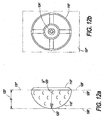
FIG. 12A is a side view of a second implement of the invention. -
FIG. 12B is a bottom view of the second implement of the invention. - Referring now to the drawings, the details of preferred embodiments of the present invention are graphically and schematically illustrated. Like elements in the drawings are represented by like numbers, and any similar elements are represented by like numbers with a different lower case letter suffix.
- Referring now to
FIGs 1A and 2 , ametal housing 20 andmetal cover plate 28 encases the passive radio-frequency transponder 124. In this embodiment, the axis of theantenna 70 is perpendicular to the critical thickness of the cover plate 26. - The present invention encompasses a fully metal-encased passive radio-frequency transponder device and its exemplary uses. The transponder device is fully metal-encased in that the encasement or jacket of the transponder device has no non-metallic gaps, spaces, cracks, pores or the like. In other words, it is an important feature of the present invention that encasement has a continuous metal surface. The present metal-encased transponder device is the basic tracking unit of a materiel tracking system, wherein implements to be tracked, especially metallic items include an embedded or affixed transponder device of the present invention.
- Referring now to
FIG. 1B , an alternative encasement has the capability to be read in two dimensions, x and y. Additionally, this embodiment of the present metal-encased, passive radio-frequency transponder is intended to be fixed to the implements to be tracked rather than having thehousing 20a be integral to the item. - Referring now to
FIG 3 , an alternative orientation of the interior space of thehousing 20 is suitable for encasement within a rod-shaped encasement. Note that on placement of the transponder device in thehousing 20, theantenna 70 maintains a perpendicular orientation to the critical thickness of the encasement, i.e. thecover plate 28. Additionally, in this embodiment, there is a second point of critical thickness at the bottom end of the interior space of thehousing 20. - Referring now to
FIG. 4A-4C , anencasement 14 illustrating a housing and cover plate configuration is shown wherein placement of the transponder unit is such that the axis of its antenna is parallel to the critical thickness of the encasement. This allows signal coupling with the antenna in adimension 90° from that ofFIGs. 1 and3 . As shown inFIG. 4B , anarcuate cover plate 16 of critical thickness encases the RFID device ofFIG. 4A . - Referring now to
FIG. 4C , thecover plate 16 on a rod portion is fixed in place over the opening of thehousing 20. The fully metal-encased passive radio-frequency transponder device 10 of the present invention thus includes ametal housing 20 having anexternal surface 22, and anopening 24 allowing access to aninterior space 30 within thehousing 20. Theopening 24 is closable with ametal cover 16. Themetal cover 16 is fixed to thehousing 20 with a metallic seal 90 (e.g. welded or soldered) so that the combinedhousing 20 and cover 16 provide asolid metal encasement 14, with no non-metal gaps, cracks, spaces, pores or the like. This is particularly important in applications where a metal implement being tracked may be subject to conditions that thetransponder unit 40 was not designed to be proof against. - The
interior space 30 of theencasement 14 is defined by the interior walls of thehousing 20 andcover plate 16. The solid metal encasement 14 (the encasement being the combination of thehousing 20 and the cover plate 16) has at least one section of its wall that is substantially a uniform thickness T between aninterior wall surface 32, adjacent which theantenna 70 of thetransponder unit 40 is disposed. The thickness T, between aninterior wall surface 32 and the opposingexternal surface 22, was less than about 0.5 mm. See Example 1. -
- Feasibility Determination: is it possible to read a passive RF transponder device through solid metal.
- Elucidate a set of electro-physical parametric limits for the capability to read a passive RF transponder device through solid metal.
- ■ Transponder design features
- ■ Thickness of the metal encasement
- ■ Read distance and orientation of the read unit to the antenna of the transponder.
-
- 601201 Sokymat GLASS TAG UNIQUE 2.12 x 12.0 Read Only 64 bit (
FIG. 6A ) - 601203 Sokymat GLASS TAG UNIQUE 3.15 x 13.3 Read Only 64 bit (
FIG. 6B ) - Test Plate C6335 (
FIG. 6C ) - Reader: RFID tag reader with Ferrite Antenna (
FIG. 6D ) - A test plate C6335 was manufactured from 17-4 Stainless Steel, which is an alloy common in orthopaedic instrumentation. Both 12mm (ITM# 601201) and 13mm (ITM# 601203) read only Glass Unique tags were imbedded into holes drilled in the plate at varying depths of 0.3mm, 0.4mm and 0.5mm. Every other hole was closed with a metallic plug which was subsequently laser-welded into the plate to encapsulate the tag inside. The remaining holes were left open as a control. The Easy Term battery powered reader was then placed adjacent to the side of the plate and prompted to read the RFID tags. In each case the control tag was read first and then the encapsulated tag was read. Exhibit D shows the test setup with the reader in place over an encapsulated RFID tag.
- All of the control tags 12mm (ITM# 601201) and 13mm (ITM# 601203) that were imbedded in open holes read successfully in the 0.3mm, 0.4mm and 0.5mm thickness. Both the 12mm (ITM# 601201) and 13mm (ITM# 601203) tag that were completely encapsulated in the metal read through the 0.3mm and 0.4mm, however both were unsuccessful at 0.5mm.
- It is clear that as long as there is an opening in the
metal housing 20 either tag could be read successfully no matter what the depth. When the tags were encapsulated the read distance was diminished but still easily readable at the 0.3mm and 0.4mm thickness. The manufacturer hypothesizes that ferrite material present in their tags and ferrite in the reader contributes to focus the signal into a tight pattern so that it can be read through metal. They believe that the ferrite material creates an alignment of the magnetic fields that attract one another, the reader pushing the signal and the tag pulling it in. Further they hypothesize that as long as the reader has a sufficiently strong ferrite core in its antennae the ferrite in the tag could be removed. Also it is hypothesized that standards tags (e.g., Sokymat's) could be encapsulated in metal and written to. Further testing will be required to prove the theory of reading tags without ferrite cored and writing to their chips through metal. -
- A passive transponder device having an iron core and wound antenna
- Less than 0.5 mm thickness of metal between the reader device and the transponder device.
- An aspect angle of the read unit head to the antenna axis of substantial 0° or 90°.
- Having determined at least one working set of electro-physical parameters the present solid metal-encased passive radio-
frequency transponder device 10 is enabled and practicable in a metal encasement in the following manner. As generally illustrated inFIG. 5 , in the preferred embodiment, apassive transponder 40 having an iron (ferrite)core antenna assembly 50 was used (part no. 601201: GLASS TAG UNIQUE 2.12 x 12.0 Read Only 64 bit and part no. 601203: GLASS TAG UNIQUE 3.15 x 13.3 Read Only 64 bit; Sokymat S.A., Switzerland). Thetransponder 40 was received within theinterior space 30 of theencasement 14. - Referring now to
FIGs. 6A and6B , specification sheets for transponder units which are practicable in the present metal-encased, passive RF transponder device are shown.FIG. 6C illustrates a test set up device used to elucidate the electro-physical parameters of the present metal-encased, passive RF transponder.FIG. 6D illustrates one of the positional relationships between the metal-encased, passive RF transponder test device ofFIG. 6C and theread 100 head of a "reader" as used to used to elucidate the electro-physical parameters. -
FIG. 7A is cross-sectional view of ahousing 20 showing thecover plate 28 sealed in place and apassive transceiver device 40 disposed in proper orientation within thehousing 20 for maximum RF signal coupling to the antenna of the device. InFIG. 7B , ahousing 20 is shown with itscover plate 28 sealed in place and apassive transceiver device 40 disposed in proper orientation within thehousing 20 as inFIG. 7A , but additionally illustrating the signal relationship between theiron core antenna 70 and a signal source outside (read head 100) and thehousing 20. - It was determined that the orientation of the
antenna 70 relative to the read device head 100 (seeFIGs. 6D and7B ) was important. That is, the dimensional or orientation aspect x or y of theantenna 70 relative to the critical thickness T portion of theencasement 14 was enabling when theaxis 54 of theantenna 70 was either substantially perpendicular to or parallel with the plane of the critical thickness T portion. Specifically, theantenna 70 was disposed adjacent theinterior wall surface 32 of theinterior space 30 and oriented to maximally couple a radio-frequency signal present at the interior wall surface to an antenna of the antenna assembly when theaxis 54 of the antenna was substantially perpendicular to (the x dimension, seeFIG. 3 ) or parallel with (the y dimension, seeFIG. 4C ) the plane of the critical thickness T portion of theencasement 14. As illustrated inFIGs. 1B and3 , theencasement 14 of thepresent transponder device 10 can be configured to have more than one critical thickness T portion, and thus be read from more than one antenna dimensional aspect x or y. Other configurations of theencasement 14 are selectable by one of ordinary skill in the art in consideration of the configuration of the implement it is to be incorporated into, and in view of the teachings and drawings disclosed herein. It may be useful in certain applications to scribe anoptional orientation mark 18 on the encasement to make readily apparent the optimal location for activating thetransponder device 10 with a reader. - In a preferred embodiment, the materiel radio-tracking and inventory system of the present invention has a tertiary organizational structure. At the first level of organization, a metallic implement to be tracked incorporates or has fixed to it the present metal-encased, passive
RF transponder device 10 described above. The present metal-encased,transponder device 10 is the first passive radio-frequency transponder in the system hierarchy. Thetransponder device 10 of the preferred embodiments disclosed herein was a read-only device. Once it was loaded with its response data, the data could not be changed by an external signal. The read-only device has advantages in a material tracking system, in that the code cannot be changed in the field, and the change used to avoid tracking of a more restricted item masking as a less restricted one. However, it is intended that thetransponder device 10 include both read-only and read-write types oftransponder units 40. - Referring now to
FIG. 8A , a typical storage bin is typically used in hospitals for containing medical instruments and supplies. A non-encased passive transceiver is attached to an external surface of the bin - the top, in this case. - Methods and procedures for entering an implement into the tracking system are known in the art. Typically, the
transponder device 10 is powered up, and its identification coding is read from memory and transmitted when activated by an appropriate reader transceiver device. At other appropriate times, as when the status of the item is changed, thetransponder device 10 is read again in conjunction with the status update. It is anticipated that the implement will be kept in astorage unit 200, such as a container or bin. SeeFIG. 8A . Thestorage unit 200 is configured to receive and store at least one implement to be tracked. Thestorage unit 200 has asurface 210 on which a second passive radio-frequency transponder 220 is mounted. Thesecond transponder 200 can be mounted on an internal surface or an external surface. - Referring now to
FIG. 8B , a non-encased passive transceiver device of a preferred embodiment is shown. Thesecond transponder 220 does not have a solid metal encasement. This is not necessary if thestorage unit 200 is not metal or RF shielded. It is encapsulated in ahousing 230, in resin of the preferred embodiment illustrated, and does have theantenna 240 andelectronics 250 typical of such devices. The secondpassive RF transponder 220 is a read-write device, and is disposed to power up, receive and write data to memory, and to read and transmit data from memory as appropriate when activated by a read/write transceiver device. The data stored or storable on thesecond transponder device 220 includes the storage unit identification code and the identification code of the implement to be tracked that is stored in theunit 200. - Referring now to
FIG. 9 , a typical bin rack typically used in hospitals holds storage bins. The rack has an active transceiver device mounted on it. Thestorage rack 260 is configured to hold thestorage units 200 in a manner to expose the second passive radio-frequency transponder 220 to be activated by a read/write. However, this configuration of thestorage rack 260 may readily be changed to accommodate other desired features, such as not having thesecond transponders 220 exposed. Additionally, thestorage rack 260 has an active radio-frequency transponder 270 mounted on it. Theactive transponder 270 is disposed to receive and write data to memory, and to read and transmit data from memory as appropriate when activated. Activation of theactive transponder 270 can be manual or automatic, and remote or local. In certain applications where it might be expected that atransportable rack 260 may move considerable distances (or to avoid it moving considerable distances) the active transponder may include a locator device (e.g. a GPS device). The read-write and read-only data processable by theactive transponder 270 may include a storage rack identification code and the identification code of the storage units held in the rack, as well as location data. Taken in combination, these elements alone and in various combinations comprise the metal encased passive radio frequency transponder and materiel tracking system of the present invention. - Referring to
FIGs. 10 ,11 ,12A, and 12B , in another example of use, an intelligent implement 110, 110' for surgical use has an implementbody 112, 112', anRFID transponder 124, 124' according to the invention, and areference device 126, 126'. The implementbody 112, 112' has astructure having features 120, 120' of precisedimensional characteristics 122, 122'. TheRFID transponder 124, 124' is encased in thebody 112, 112', and is capable of storing information about select precisedimensional characteristics 122, 122' of the body. Thereference device 126, 126' is defined on the implement, from which the dimensional characteristics are referenced for use in a computer-aidednavigation system 130. Thereference device 126 is preferably a navigational sputnik affixed to thebody 112. Thesputnik 126 hasfeatures 132 which enable thenavigation system 130 to know the precise orientation of the implement in three dimensional space. - In the implement 110, the sputnik or
satellite 126, includes a plurality ofspatial reflectors 132 whose location is readable by a position sensing device (e.g. multiple, spatially displaced,infrared detectors 133, radar, GPS, etc) of thenavigation system 130 connected to a computer of thenavigation system 130 and, given that the plurality ofspatial reflectors 132 are located a known vector distance 134 away from areference plane - The
spatial reflectors 132 are infrared reflectors. - The reference plane is a
tool attachment plane 136. - In a preferred embodiment, the implement 110, 110' is adapted for connecting with a second intelligent implement 110', 110, the two together creating a compound intelligent implement 140. An appropriate attachment means may be a bayonet mechanism, such as that shown in
WO 03/092513 - The second implement 110' is a tool which connects to a
reference interface 142 located a known distance away from areference plane distance value 122, 122'. - The
RFID transponder 124, 124' is a readable RFID chip; a readable, writable RFID chip, readable; and/or writable by areader 125. - The
RFID transponder 124, 124' is embedded or encased in the implement. - The
RFID transponder 124, 124' may be embedded or encased in the implement under athin metal cover 125. - In another embodiment, the invention is included in an implement which is one of a lot of
intelligent implements 110, 110' for use in holding atool 110 to be used in computer assistednavigation system 130, each implement having an implementbody 112, 112' made according to manufacturing processes that reproduce dimensional characteristics which vary amongst themselves within a tolerance band, wherein, in order to provide greater accuracy during computer assisted surgery, prior to delivery to the point of use, each implement 110, 110' is measured for its particular precise dimensional reference characteristic 122, 123, 122', 123' and such dimensional characteristic is recorded via anRFID transponder 124, 124' and affixed thereto, so as to be able to be read and input into a register of a computer conducting computer aided navigational surgery therewith, thus providing the computer with more accurate tool position information. - The dimensional reference characteristic 123' is the vector distance between a
navigational sputnik 126 affixed to the implement and areference plane 136 of thetool engaging portion 142 of the implement. - An object of the invention is to provide an implement and a system which is capable of hermetically encasing an RFID transponder in metal, so as to better protect the transponder from harsh sterilization environments.
- Another object of the invention is to provide an implement and a system that improves inventory management of expensive and mission-critical equipment.
- Another object of the invention is to enable the manufacturing of implements using conventional and relatively inexpensive means, while assuring precision when such implements are used in computer assisted navigational surgery.
- Multiple variations and modifications are possible in the embodiments of the invention described here. Although certain illustrative embodiments of the invention have been shown and described here, a wide range of modifications, changes, and substitutions is contemplated in the foregoing disclosure. In some instances, some features of the present invention may be employed without a corresponding use of the other features. Accordingly, it is appropriate that the foregoing description be construed broadly and understood as being given by way of illustration and example only, the scope of the invention being limited only by the appended claims.
Claims (14)
- A metal-encased passive radio-frequency transponder assembly (10, 110, 110') comprising:- a metal housing (20, 112, 112') having an external surface (22), an opening (24) accessing an interior space (30), the opening closed with a metal cover (28) to provide a solid metal encasement (14), the interior space (30) of the encasement being defined by the interior walls of the housing and cover; and- a passive radio-frequency transponder device (124, 124'), the passive transponder device received within the interior space (30) of the housing (20, 112, 112'), the passive transponder device having an iron core antenna assembly (50), the antenna assembly being disposed adjacent the interior wall surface of the interior space (30) and oriented to effectively couple a radio-frequency signal present at the interior wall surface to an antenna (70) of the antenna assembly (50), characterized in that that the solid metal encasement (14) has a continuous metal surface and the cover has a substantially uniform wall thickness (T) between the interior wall surface, adjacent which, the antenna assembly (50) is disposed, and the opposing external surface (22), the thickness (T) of the cover being about 0.5 mm or less.
- An intelligent implement (110, 110') for surgical use, the implement comprising:a an implement body (112, 112') having a structure comprising features (120, 120') of precise dimensional characteristics (122, 122');b. a passive radio-frequency transponder (124, 124') encased in at least a metal portion of the body (112, 112') the portion being a metal housing (20) having a continuous metal surface, and having a substantially uniform wall thickness (T) between the interior wall surface adjacent which an antenna assembly (50) of the transponder is disposed and the opposing external surface (22) of less that about 0.5 mm, capable of storing information about select precise dimensional characteristics (122, 122') of the body; andc. a reference device (126, 126') defined on the implement, from which the dimensional characteristics are referenced for use in a computer-aided navigation system (130).
- The implement (110, 110') of claim 2, wherein the reference device (126) is a navigational sputnik affixed to the body (10, 112, 112'), the sputnik (126) having features (132) which enable the navigation system (130) to know the precise orientation of the implement in three dimensional space.
- The implement (110, 110') of claim 3, wherein sputnik (126) comprises a plurality of spatial reflectors (132) whose location is readable by a position sensing device of the navigation system (130) connected to a computer of the navigation system (130) and, given that the plurality of spatial reflectors (132) are located a known vector distance (34) away from a reference plane (136, 137, 136', 137'), then the location of this reference plane can be accurately ascertained.
- The implement (110, 110') of claim 4, wherein the position sensing device is a multiple, spatially displaced, infrared detectors (133).
- The implement (110, 110') of claim 4, wherein the position sensing device is a radar.
- The implement (110, 110') of claim 4, wherein the position sensing device is a GPS.
- The implement (110, 110') of claim 4, wherein the spatial reflectors (132) are infrared reflectors.
- The implement (110, 110') of claim 4, wherein the reference plane is a tool attachment plane (136).
- The implement (110, 110') of claim 2, adapted for connecting with a second intelligent implement (110', 110), the two together creating a compound intelligent implement (140).
- The implement (110, 110') of claim 10, wherein the second implement (110') is a tool which connects to a reference interface (142) located a known distance away from a reference plane (136, 137), the corresponding RFID transponder (124, 124') of which being adapted to store the known distance value (122, 122').
- The implement (110,110') of claim 2, wherein the RFID transponder (124, 124') is a readable RFID chip, readable by a reader (125).
- The implement (110,110') of claim 2, wherein the RFID transponder (124, 124') is a readable, writable RFID chip, readable and writable by a reader (125).
- The implement (110, 110') of claim 2, wherein the RFID transponder (124, 124') is embedded or encased in the implement under a thin metal cover (125).
Applications Claiming Priority (2)
| Application Number | Priority Date | Filing Date | Title |
|---|---|---|---|
| US63923504P | 2004-12-22 | 2004-12-22 | |
| PCT/IB2005/003922 WO2006067610A2 (en) | 2004-12-22 | 2005-12-15 | Intelligent implement having metal encased passive radio frequency transponder and examples of use |
Publications (2)
| Publication Number | Publication Date |
|---|---|
| EP1846873A2 EP1846873A2 (en) | 2007-10-24 |
| EP1846873B1 true EP1846873B1 (en) | 2009-03-25 |
Family
ID=35953323
Family Applications (1)
| Application Number | Title | Priority Date | Filing Date |
|---|---|---|---|
| EP05818173A Active EP1846873B1 (en) | 2004-12-22 | 2005-12-15 | Intelligent implement having metal encased passive radio frequency transponder and examples of use |
Country Status (5)
| Country | Link |
|---|---|
| US (1) | US7819318B2 (en) |
| EP (1) | EP1846873B1 (en) |
| AT (1) | ATE426865T1 (en) |
| DE (1) | DE602005013581D1 (en) |
| WO (1) | WO2006067610A2 (en) |
Families Citing this family (16)
| Publication number | Priority date | Publication date | Assignee | Title |
|---|---|---|---|---|
| DE602005013795D1 (en) * | 2005-11-18 | 2009-05-20 | Airsec Sas | Container and capsule with transponder |
| US8600478B2 (en) | 2007-02-19 | 2013-12-03 | Medtronic Navigation, Inc. | Automatic identification of instruments used with a surgical navigation system |
| FR2930887A1 (en) * | 2008-05-06 | 2009-11-13 | Ats Sferic Stellite S A S Soc | INVASIVE SURGICAL INSTRUMENT WITH TRANSPONDER |
| US8776644B2 (en) | 2012-01-23 | 2014-07-15 | Stanley Black & Decker, Inc. | Electronic identifier attachment for inventory items |
| US8870078B2 (en) | 2012-02-08 | 2014-10-28 | Stanley Black & Decker, Inc. | Hand tool having an electronic identification device |
| BR112014026444A2 (en) * | 2012-04-27 | 2017-06-27 | Vallourec Oil & Gas France | reinforced rfid labels |
| US8690068B2 (en) | 2012-05-21 | 2014-04-08 | Warsaw Orthopedic, Inc. | Miniaturized UHF RFID tag for implantable medical device |
| US9089952B2 (en) | 2012-08-14 | 2015-07-28 | Stanley Black & Decker, Inc. | Electronic identifier attachments for bits |
| ES2535154T5 (en) | 2012-09-24 | 2022-10-26 | Satyatek Sa | Assembly procedure of a radio identification capsule (RFID) |
| CN203338387U (en) * | 2013-05-17 | 2013-12-11 | 鸿富锦精密工业(深圳)有限公司 | Tubular electronic label and suitcase using same |
| ES2670649T3 (en) * | 2015-03-02 | 2018-05-31 | Gemalto Sa | Manufacturing procedure of a radio frequency device with passive wired antenna |
| DE102015120153A1 (en) * | 2015-11-20 | 2017-05-24 | Bilz Werkzeugfabrik Gmbh & Co. Kg | Tool with RFID chip and method for attaching such to a tool |
| EP3698279A1 (en) * | 2017-10-16 | 2020-08-26 | GCL International Sarl | Closure member |
| EP3576248B1 (en) * | 2018-05-31 | 2023-05-31 | STMicroelectronics Austria GmbH | Nfc reader |
| DE102019122349A1 (en) * | 2019-08-20 | 2021-02-25 | Aesculap Ag | Integrated RFID tag holder |
| US11289195B2 (en) * | 2020-08-09 | 2022-03-29 | Kevin Patel | System for remote medical care |
Family Cites Families (17)
| Publication number | Priority date | Publication date | Assignee | Title |
|---|---|---|---|---|
| US3531582A (en) * | 1965-12-15 | 1970-09-29 | Zenith Radio Corp | Subscription television receiver with removable code-bearing element |
| US5370675A (en) * | 1992-08-12 | 1994-12-06 | Vidamed, Inc. | Medical probe device and method |
| US5218187A (en) * | 1990-01-18 | 1993-06-08 | Norand Corporation | Hand-held data capture system with interchangeable modules |
| US5787886A (en) * | 1993-03-19 | 1998-08-04 | Compass International Incorporated | Magnetic field digitizer for stereotatic surgery |
| US5405346A (en) * | 1993-05-14 | 1995-04-11 | Fidus Medical Technology Corporation | Tunable microwave ablation catheter |
| FR2716281B1 (en) * | 1994-02-14 | 1996-05-03 | Gemplus Card Int | Method of manufacturing a contactless card. |
| KR19990064209A (en) * | 1995-10-13 | 1999-07-26 | 트랜스바스큘라, 인코포레이티드 | Apparatus, Systems, and Methods for Interstitial Acupoint Intervention |
| US6176425B1 (en) * | 1998-09-10 | 2001-01-23 | Xerox Corporation | Information management system supporting multiple electronic tags |
| US6254389B1 (en) * | 1999-09-20 | 2001-07-03 | Marc Seghatol | Hand-held microwave intra-oral dental system |
| US6233490B1 (en) * | 1999-02-09 | 2001-05-15 | Kai Technologies, Inc. | Microwave antennas for medical hyperthermia, thermotherapy and diagnosis |
| US6277113B1 (en) * | 1999-05-28 | 2001-08-21 | Afx, Inc. | Monopole tip for ablation catheter and methods for using same |
| DE10014542C2 (en) * | 2000-03-23 | 2003-11-20 | Aesculap Ag & Co Kg | Detection system and detection method for surgical instruments and materials |
| CN1251131C (en) | 2000-07-19 | 2006-04-12 | 株式会社哈尼克斯 | RFID tag housing structure, RFID tag installation structure and RFID tag communication method |
| DE20015893U1 (en) * | 2000-09-14 | 2001-01-25 | Aesculap Ag & Co Kg | Medical instrument |
| US6503191B1 (en) * | 2001-11-09 | 2003-01-07 | Carl W. Miller | Molecular absorption resonance system |
| DE20213243U1 (en) * | 2002-08-29 | 2002-10-17 | Aesculap Ag & Co Kg | Medical instrument |
| ITVR20020112A1 (en) * | 2002-11-05 | 2004-05-06 | Marco Rossi | POSITIVE IDENTIFICATION DEVICE PARTICULARLY FOR |
-
2005
- 2005-12-15 DE DE602005013581T patent/DE602005013581D1/en active Active
- 2005-12-15 US US11/577,092 patent/US7819318B2/en active Active
- 2005-12-15 AT AT05818173T patent/ATE426865T1/en not_active IP Right Cessation
- 2005-12-15 WO PCT/IB2005/003922 patent/WO2006067610A2/en active Application Filing
- 2005-12-15 EP EP05818173A patent/EP1846873B1/en active Active
Also Published As
| Publication number | Publication date |
|---|---|
| WO2006067610A2 (en) | 2006-06-29 |
| EP1846873A2 (en) | 2007-10-24 |
| US20090283595A1 (en) | 2009-11-19 |
| ATE426865T1 (en) | 2009-04-15 |
| WO2006067610B1 (en) | 2006-11-30 |
| WO2006067610A3 (en) | 2006-08-10 |
| US7819318B2 (en) | 2010-10-26 |
| DE602005013581D1 (en) | 2009-05-07 |
Similar Documents
| Publication | Publication Date | Title |
|---|---|---|
| EP1846873B1 (en) | Intelligent implement having metal encased passive radio frequency transponder and examples of use | |
| US8035485B2 (en) | System for tracking vessels in automated laboratory analyzers by radio frequency identification | |
| US8988896B2 (en) | Field device for automation technology | |
| EP1837809A1 (en) | Ic tag storing case | |
| EP1898217A2 (en) | Sample transport rack | |
| US20090315681A1 (en) | Multi-modal transponder and method and apparatus to detect same | |
| US20070008141A1 (en) | Battery identification system and method | |
| CN111868748A (en) | Metal fastener with embedded RFID tag and production method thereof | |
| CN103703475A (en) | Rfid tag | |
| US7227721B1 (en) | Multi-directional cartridge memory antenna designs | |
| KR20050116587A (en) | Survey control point indicator device and survey indicator management system using the same | |
| JP2002049900A (en) | Method and system for managing article by using electromagnetic induction tag | |
| US9803444B2 (en) | Obtaining data from an underwater component | |
| EP2680200B1 (en) | Production tool having RFID device mounted within a dielectric inclusion | |
| US9898698B2 (en) | Production tool having RFID device mounted within a dielectric inclusion | |
| CA2744769C (en) | System and method for multiple reading interface with a simple rfid antenna | |
| JP3141694U (en) | Indicator | |
| US20230252257A1 (en) | Medical instrument having an installed transponder module, and medical transponder communication system | |
| JP2004294288A (en) | Measuring system of covering depth and measuring method of covering depth | |
| JP3837151B2 (en) | Tagged bolt | |
| JP4520759B2 (en) | Meter device and meter management system using the same | |
| US20240164866A1 (en) | Integrated rfid tag in a manual instrument | |
| US20220061760A1 (en) | Hermetic enclosure for implantable sensors | |
| BR102015032172A2 (en) | MONITORING OF SURGICAL INSTRUMENTS BY UHF RADIOFREQUENCY DURING SURGICAL TASK AND CYCLE CLEANING, STERILIZATION AND MAINTENANCE | |
| KR200359649Y1 (en) | Survey Control Point Indicator Device and Survey Indicator Management System Using the Same |
Legal Events
| Date | Code | Title | Description |
|---|---|---|---|
| PUAI | Public reference made under article 153(3) epc to a published international application that has entered the european phase |
Free format text: ORIGINAL CODE: 0009012 |
|
| 17P | Request for examination filed |
Effective date: 20070717 |
|
| AK | Designated contracting states |
Kind code of ref document: A2 Designated state(s): AT BE BG CH CY CZ DE DK EE ES FI FR GB GR HU IE IS IT LI LT LU LV MC NL PL PT RO SE SI SK TR |
|
| DAX | Request for extension of the european patent (deleted) | ||
| GRAP | Despatch of communication of intention to grant a patent |
Free format text: ORIGINAL CODE: EPIDOSNIGR1 |
|
| GRAS | Grant fee paid |
Free format text: ORIGINAL CODE: EPIDOSNIGR3 |
|
| GRAA | (expected) grant |
Free format text: ORIGINAL CODE: 0009210 |
|
| AK | Designated contracting states |
Kind code of ref document: B1 Designated state(s): AT BE BG CH CY CZ DE DK EE ES FI FR GB GR HU IE IS IT LI LT LU LV MC NL PL PT RO SE SI SK TR |
|
| REG | Reference to a national code |
Ref country code: GB Ref legal event code: FG4D |
|
| REG | Reference to a national code |
Ref country code: CH Ref legal event code: EP |
|
| REG | Reference to a national code |
Ref country code: IE Ref legal event code: FG4D |
|
| REF | Corresponds to: |
Ref document number: 602005013581 Country of ref document: DE Date of ref document: 20090507 Kind code of ref document: P |
|
| PG25 | Lapsed in a contracting state [announced via postgrant information from national office to epo] |
Ref country code: FI Free format text: LAPSE BECAUSE OF FAILURE TO SUBMIT A TRANSLATION OF THE DESCRIPTION OR TO PAY THE FEE WITHIN THE PRESCRIBED TIME-LIMIT Effective date: 20090325 Ref country code: SI Free format text: LAPSE BECAUSE OF FAILURE TO SUBMIT A TRANSLATION OF THE DESCRIPTION OR TO PAY THE FEE WITHIN THE PRESCRIBED TIME-LIMIT Effective date: 20090325 Ref country code: LT Free format text: LAPSE BECAUSE OF FAILURE TO SUBMIT A TRANSLATION OF THE DESCRIPTION OR TO PAY THE FEE WITHIN THE PRESCRIBED TIME-LIMIT Effective date: 20090325 |
|
| RAP2 | Party data changed (patent owner data changed or rights of a patent transferred) |
Owner name: GREATBATCH MEDICAL SA |
|
| PG25 | Lapsed in a contracting state [announced via postgrant information from national office to epo] |
Ref country code: PL Free format text: LAPSE BECAUSE OF FAILURE TO SUBMIT A TRANSLATION OF THE DESCRIPTION OR TO PAY THE FEE WITHIN THE PRESCRIBED TIME-LIMIT Effective date: 20090325 Ref country code: LV Free format text: LAPSE BECAUSE OF FAILURE TO SUBMIT A TRANSLATION OF THE DESCRIPTION OR TO PAY THE FEE WITHIN THE PRESCRIBED TIME-LIMIT Effective date: 20090325 Ref country code: AT Free format text: LAPSE BECAUSE OF FAILURE TO SUBMIT A TRANSLATION OF THE DESCRIPTION OR TO PAY THE FEE WITHIN THE PRESCRIBED TIME-LIMIT Effective date: 20090325 Ref country code: SE Free format text: LAPSE BECAUSE OF FAILURE TO SUBMIT A TRANSLATION OF THE DESCRIPTION OR TO PAY THE FEE WITHIN THE PRESCRIBED TIME-LIMIT Effective date: 20090625 |
|
| NLV1 | Nl: lapsed or annulled due to failure to fulfill the requirements of art. 29p and 29m of the patents act | ||
| PG25 | Lapsed in a contracting state [announced via postgrant information from national office to epo] |
Ref country code: BE Free format text: LAPSE BECAUSE OF FAILURE TO SUBMIT A TRANSLATION OF THE DESCRIPTION OR TO PAY THE FEE WITHIN THE PRESCRIBED TIME-LIMIT Effective date: 20090325 |
|
| PG25 | Lapsed in a contracting state [announced via postgrant information from national office to epo] |
Ref country code: PT Free format text: LAPSE BECAUSE OF FAILURE TO SUBMIT A TRANSLATION OF THE DESCRIPTION OR TO PAY THE FEE WITHIN THE PRESCRIBED TIME-LIMIT Effective date: 20090831 Ref country code: ES Free format text: LAPSE BECAUSE OF FAILURE TO SUBMIT A TRANSLATION OF THE DESCRIPTION OR TO PAY THE FEE WITHIN THE PRESCRIBED TIME-LIMIT Effective date: 20090706 Ref country code: EE Free format text: LAPSE BECAUSE OF FAILURE TO SUBMIT A TRANSLATION OF THE DESCRIPTION OR TO PAY THE FEE WITHIN THE PRESCRIBED TIME-LIMIT Effective date: 20090325 Ref country code: CZ Free format text: LAPSE BECAUSE OF FAILURE TO SUBMIT A TRANSLATION OF THE DESCRIPTION OR TO PAY THE FEE WITHIN THE PRESCRIBED TIME-LIMIT Effective date: 20090325 |
|
| PG25 | Lapsed in a contracting state [announced via postgrant information from national office to epo] |
Ref country code: RO Free format text: LAPSE BECAUSE OF FAILURE TO SUBMIT A TRANSLATION OF THE DESCRIPTION OR TO PAY THE FEE WITHIN THE PRESCRIBED TIME-LIMIT Effective date: 20090325 Ref country code: IS Free format text: LAPSE BECAUSE OF FAILURE TO SUBMIT A TRANSLATION OF THE DESCRIPTION OR TO PAY THE FEE WITHIN THE PRESCRIBED TIME-LIMIT Effective date: 20090725 Ref country code: SK Free format text: LAPSE BECAUSE OF FAILURE TO SUBMIT A TRANSLATION OF THE DESCRIPTION OR TO PAY THE FEE WITHIN THE PRESCRIBED TIME-LIMIT Effective date: 20090325 Ref country code: NL Free format text: LAPSE BECAUSE OF FAILURE TO SUBMIT A TRANSLATION OF THE DESCRIPTION OR TO PAY THE FEE WITHIN THE PRESCRIBED TIME-LIMIT Effective date: 20090325 |
|
| REG | Reference to a national code |
Ref country code: FR Ref legal event code: CD |
|
| PG25 | Lapsed in a contracting state [announced via postgrant information from national office to epo] |
Ref country code: BG Free format text: LAPSE BECAUSE OF FAILURE TO SUBMIT A TRANSLATION OF THE DESCRIPTION OR TO PAY THE FEE WITHIN THE PRESCRIBED TIME-LIMIT Effective date: 20090625 Ref country code: DK Free format text: LAPSE BECAUSE OF FAILURE TO SUBMIT A TRANSLATION OF THE DESCRIPTION OR TO PAY THE FEE WITHIN THE PRESCRIBED TIME-LIMIT Effective date: 20090325 |
|
| PLBE | No opposition filed within time limit |
Free format text: ORIGINAL CODE: 0009261 |
|
| STAA | Information on the status of an ep patent application or granted ep patent |
Free format text: STATUS: NO OPPOSITION FILED WITHIN TIME LIMIT |
|
| 26N | No opposition filed |
Effective date: 20091229 |
|
| PG25 | Lapsed in a contracting state [announced via postgrant information from national office to epo] |
Ref country code: MC Free format text: LAPSE BECAUSE OF NON-PAYMENT OF DUE FEES Effective date: 20100701 |
|
| REG | Reference to a national code |
Ref country code: CH Ref legal event code: PL |
|
| PG25 | Lapsed in a contracting state [announced via postgrant information from national office to epo] |
Ref country code: LI Free format text: LAPSE BECAUSE OF NON-PAYMENT OF DUE FEES Effective date: 20091231 Ref country code: CH Free format text: LAPSE BECAUSE OF NON-PAYMENT OF DUE FEES Effective date: 20091231 Ref country code: GR Free format text: LAPSE BECAUSE OF FAILURE TO SUBMIT A TRANSLATION OF THE DESCRIPTION OR TO PAY THE FEE WITHIN THE PRESCRIBED TIME-LIMIT Effective date: 20090626 Ref country code: IE Free format text: LAPSE BECAUSE OF NON-PAYMENT OF DUE FEES Effective date: 20091215 |
|
| PG25 | Lapsed in a contracting state [announced via postgrant information from national office to epo] |
Ref country code: IT Free format text: LAPSE BECAUSE OF FAILURE TO SUBMIT A TRANSLATION OF THE DESCRIPTION OR TO PAY THE FEE WITHIN THE PRESCRIBED TIME-LIMIT Effective date: 20090325 |
|
| PG25 | Lapsed in a contracting state [announced via postgrant information from national office to epo] |
Ref country code: LU Free format text: LAPSE BECAUSE OF NON-PAYMENT OF DUE FEES Effective date: 20091215 |
|
| PG25 | Lapsed in a contracting state [announced via postgrant information from national office to epo] |
Ref country code: HU Free format text: LAPSE BECAUSE OF FAILURE TO SUBMIT A TRANSLATION OF THE DESCRIPTION OR TO PAY THE FEE WITHIN THE PRESCRIBED TIME-LIMIT Effective date: 20090926 |
|
| PG25 | Lapsed in a contracting state [announced via postgrant information from national office to epo] |
Ref country code: TR Free format text: LAPSE BECAUSE OF FAILURE TO SUBMIT A TRANSLATION OF THE DESCRIPTION OR TO PAY THE FEE WITHIN THE PRESCRIBED TIME-LIMIT Effective date: 20090325 |
|
| PG25 | Lapsed in a contracting state [announced via postgrant information from national office to epo] |
Ref country code: CY Free format text: LAPSE BECAUSE OF FAILURE TO SUBMIT A TRANSLATION OF THE DESCRIPTION OR TO PAY THE FEE WITHIN THE PRESCRIBED TIME-LIMIT Effective date: 20090325 |
|
| REG | Reference to a national code |
Ref country code: FR Ref legal event code: PLFP Year of fee payment: 11 |
|
| REG | Reference to a national code |
Ref country code: FR Ref legal event code: PLFP Year of fee payment: 12 |
|
| REG | Reference to a national code |
Ref country code: FR Ref legal event code: PLFP Year of fee payment: 13 |
|
| PGFP | Annual fee paid to national office [announced via postgrant information from national office to epo] |
Ref country code: GB Payment date: 20231026 Year of fee payment: 19 |
|
| PGFP | Annual fee paid to national office [announced via postgrant information from national office to epo] |
Ref country code: FR Payment date: 20231009 Year of fee payment: 19 Ref country code: DE Payment date: 20231017 Year of fee payment: 19 |