EP1845005A2 - Rail vehicle and rail traffic - Google Patents
Rail vehicle and rail traffic Download PDFInfo
- Publication number
- EP1845005A2 EP1845005A2 EP06090030A EP06090030A EP1845005A2 EP 1845005 A2 EP1845005 A2 EP 1845005A2 EP 06090030 A EP06090030 A EP 06090030A EP 06090030 A EP06090030 A EP 06090030A EP 1845005 A2 EP1845005 A2 EP 1845005A2
- Authority
- EP
- European Patent Office
- Prior art keywords
- rail
- track
- vehicle
- rails
- movement
- Prior art date
- Legal status (The legal status is an assumption and is not a legal conclusion. Google has not performed a legal analysis and makes no representation as to the accuracy of the status listed.)
- Withdrawn
Links
Images


Classifications
-
- B—PERFORMING OPERATIONS; TRANSPORTING
- B61—RAILWAYS
- B61B—RAILWAY SYSTEMS; EQUIPMENT THEREFOR NOT OTHERWISE PROVIDED FOR
- B61B15/00—Combinations of railway systems
-
- B—PERFORMING OPERATIONS; TRANSPORTING
- B61—RAILWAYS
- B61K—AUXILIARY EQUIPMENT SPECIALLY ADAPTED FOR RAILWAYS, NOT OTHERWISE PROVIDED FOR
- B61K5/00—Apparatus for placing vehicles on the track; Derailers; Lifting or lowering rail vehicle axles or wheels
- B61K5/02—Devices secured to the vehicles; Turntables integral with the vehicles
Definitions
- the invention has as its object to provide a traffic system which is suitable for passenger and large transport and large parts of air traffic through a wide-branched small rail suitable track rail system, possibly in combination with a partially evacuated tube system for fast long-distance traffic. It should ultimately be possible to enter at almost any point with rail connection in a cabin and even get off on another continent again arbitrarily.
- an individual rail transport is sought, which relies on the passenger transport in small cabins and narrow gauge, by the parallel guidance of several lanes mainly in the amount gradually increased .. Nevertheless, it should also be handled most of the freight traffic with a smooth transition from the present conditions. Due to the variety of possible uses of the invention, the system diversity of similar means of transport should be overcome.
- Entry and exit should be made possible for the public transport network pretty much anywhere without being tied to scheduled stops.
- the traffic should be made smoother, safer, more environmentally friendly and more economical.
- the variety of execution also wants to take account of economic efficiency and meet social psychological expectations. It may be assumed that initially the modellers will be interested in the proposed system, which should therefore also be protected in the form of the toy, even in virtual use as a computer game.
- Elevated rail vehicles are known, but tied to stops or to switch positions; usually they are large vehicles on wide, elaborate rails, the load is only considered separately. Tube tracks have been developed out of the tunnel situation.
- a narrow gauge rail track system which preferably parallel running several rails or tracks, and in turn preferably in each case in the height stepwise but also perpendicularly elevated.
- cabins carrying a device which allows the passage from one of said tracks to an adjacent one at almost any location along the route.
- the device consists of a lifting device for the cabin (with the main vehicle) connected to at least one transverse displacement device (carriage) - both summarized as transport links - wherein motor-driven rollers or runners (as a motor car or driving devices) before changing the car to the other track with this as Rail sliding devices are brought into a rolling or sliding relationship.
- the device can also combine vertical and transverse displacement movement in a common oscillatory movement.
- the elevation of the parallel track is largely sought, but can be omitted for cost reasons, and in places, also.
- the fixed rails can be resorted to flexible, namely ropes.
- At least two on tracks with respect to their rail seat independent of each other driving devices (called below motor car) provided which are connected via a frame with the cabin, that enclosed by them each cabin with at least one of these driving devices a lifting device can be brought at least to the height of the adjacent rail, wherein the thereby entrained rail sliding device (wheel or skid) via a horizontal pushing movement and to obtain a rail undercut for the outer wheel or the outer skid, if necessary, a tilting or lever movement of their holder or the carrying carriage is brought into contact with the adjacent track.
- driving devices called below motor car
- each wheel of a traveling device illustrated as a rectangle represents a wheel with a flange, as shown for example in the top left of FIG.
- An extension of the variations of rails and wheels and training wheels was tried.
- Facilities for the turnout passage with temporary elimination of the support wheels, for finding rails and switches and adjustment of the wheel position to the rails, especially in the vehicle lowering also for freight traffic and novel turnouts are presented.
- the load cabin can be supported on several tracks on separate driving devices and also be enlarged according to the function rooms provided for the claimed tracks. Heavier and longer goods can also be distributed to several load cabins, and distributed with the use of hanging rail slide devices on cables heavy duty further lengthwise on the rails. Controlled by measuring devices lifting devices in conjunction with the driving devices (wheels or runners) allow a functionally favorable load distribution on the latter and thus on the rails, which when included for the transport task of the near-earth holding track of the same is assigned the main load.
- the supports for rails, ropes or tubes can be made of iron, steel or reinforced concrete, but in future may not only consist of toys made of special plastic materials whose interwoven structure may perhaps be bionically designed and used to save weight.
- window blinds connected with screen transmission of a traffic-calmed environment or mirror devices can also be used to remedy the perception of the pillar.
- the corresponding pressure-resistant passenger cabins are preferably spent in a transfer center with tower-like arrangement and vehicle elevator systems each in an assembly cell, where the cabs decoupled from their rail sliding and replaced by a new linear motor.
- seats and containers are exchanged between parallel cabins of different equipment.
- luggage and person control before the smuggling takes place here as possible.
- the presented invention mainly has the advantage that the flowing traffic can be raised especially in urban areas, but at the same time almost at ground level almost at any desired location and can be exited.
- the parking space shortage as it is today characteristic of cars, has an end for the passenger traffic, the number of passenger transport units can be reduced, since they can be circulated to the demand calculated by the section center in corresponding places and parked on less stressed parking lanes.
- the traffic safety can be significantly increased by the ban of the cars on sports tracks for the users of the new means of transport but also for cyclists, pedestrians, especially for children, the traffic flow while avoiding congestion and stop even before intersections are significantly accelerated.
- a maximum traffic density can be achieved by means of closed arranged pylons (columns) with rail arrangement on top of each other, ie when ascending and descending are limited to a few tracks and holding options on bottlenecks are limited to a few tracks. Access may also be provided via elevated sidewalks and sidings. The elevation is also an essential psychological requirement, since the perception closely adjacent traffic, especially oncoming traffic, is unbearable. Since every abandoned car is immediately rearranged in the traffic flow, today's parking space emergency can be effectively countered; In addition, the frequency of accidents can be effectively reduced. Biotopes no longer need to be cut.
- connection of the elevated rail system with a part-evacuated pipe system for long-distance traffic would allow, without changeover and the associated inconvenience or only short-term change, to use the largely automated system also for the reduction of air traffic.
- FIG. 1 shows, in the upper left in a vertical section, right next to it in a cross section and below in two longitudinal sections in the functional stages A and B, on a scale of 1:40, like a climbing vehicle ascending from a track to a higher one.
- the five sub-components namely cabin (21) and with wheels, axle (2) and motor (1) on the rails running motor car (14,16), supported by the (outer) frame (17), of which Cabin is detachable.
- the hinge (19) on the frame (enlarged detail below) allows its slight pivoting.
- Cabin (21) and motor vehicle (16) are raised via their attachment to the inner tube of the telescopic columns (3) under telescopic extension of the articulated column (4) between the cabin and the towing vehicle (14) in stage B.
- a gap in the frame (17) allows the lateral extension of the carriage (5) of the motor vehicle (14) on telescopic tubes on the higher track (see Fig.2).
- the dot-dashed contour lines (27) give an indication of an aerodynamic exterior design.
- the motor vehicle (16) is because of the compressor or circulation pump (15) for the pneumatic or hydraulic actuation of the telescopic connections above the engine and the aerodynamics because (dash-dotted curve) higher than the motor car (14).
- the means for operating the push and pull devices, whether pneumatic or hydraulic pistons, cables or telescopic threads will be described later.
- the stages A - D in Figure 2 describe in vertical section a vehicle ascent by lifting the telescopic columns, which follows the lateral extension of the carriage (5), which follow the rest of the vehicle.
- the second track rail is mounted slightly higher on the ascending spar of the carrier and is functionally stressed from below due to leverage. This becomes clearer from the enlarged vertical section detail at the bottom right with rails (22, 23), motor (1) and axle (2) and a support wheel (25) against overturning.
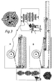
- Figure 3 shows for the operation of the telescopic column by pulley top left a cross section with pulley projections and right of the detail of a cable drum in conjunction with the motor unit in vertical section. in the middle and on the right - on the right about almost the length of the leaf - a longitudinal section through a Motor car with attached telescopic column, the latter being shown on the left in collapsed and right in the extended state.
- the scale is approximately 1:10 for the latter parts.
- Below in scale 1:20 a vertical section through a motor vehicle with the essential parts for the rope drive.
- Bottom right a variant of the pulley assembly on a telescopic column in cross section on a scale of 1: 10. Only for the function of the pulley considerable parts, such as rope pulleys were taken into account.
- the rope runs in a kind of cycle over the smaller cable drum in the opposite direction for the lowering of the telescopic column.
- FIG. 4 shows, in a plan view, on a scale of 1: 20, in the functional stages A - C the use of two pulley trains (31, 32) during the sideward movement of the motor (1) in the carriage of a motor vehicle.
- the movement of the ram (33) of the double-acting hydraulic pump is tripled in terms of the working travel in both directions and the motor spent from its outer positions (A, C) for the right and left extended carriage also under B in the middle position at the same high track rails.
- the figure 5 shows left top in a longitudinal section on a scale of 1:10 with strong length shortening the telescopic threaded tubes (262), which instead of about the hydraulic piston (Fig.9) or pulleys (Fig.3,10) with motor drive of the gear at the left end can serve as a push-pull device.
- the telescopic threaded tubes (262) instead of about the hydraulic piston (Fig.9) or pulleys (Fig.3,10) with motor drive of the gear at the left end can serve as a push-pull device.
- the essential functional elements are again drawn out in a scale of 1: 20, rotated for space reasons by 90 degrees.
- At the top right there is a sketch of the basic circuit for the pump function via a 5/2-way valve.
- the two telescopic columns (3) are arranged lying here in the carriage (5) and can extend this both to the right (B) and to the left (D), depending on which the latching switch (36) are triggered in their expansion by fluid pressure, which hold the ends of the double pumps (34, 35) to the side connecting plates and thus the slide left or right.
- the telescopic columns have mainly the function of the supporting slide frame, their one-sided pump function could also be omitted.
- the hydraulic double pumps (34, 35) staggered for stroke extension by means of slide hinge (37) also allow slide return from both directions as double-acting (the bold black dots denote the attachment of the cylinder-piston elements to the connecting plates).
- FIG. 6 shows a solution for a lateral lead-out of the carriage with the chassis of engine, engine axle and wheels in a better demonstration of superimposed storable parts slightly widened elevation by a towing vehicle in the scale 1: 40, top left with extended (B), right of it in retracted (A) state. Left below the elevation in vertical section details the schematic representation of the tilting function for the motor axis for positioning the wheels between the lower outer (22) and upper inner (23) track rail.
- FIG. 7 shows an exploded motor vehicle in an elevation in the scale of about 1:40, demonstrating the variant of the track rail change;
- the reciprocating motion of a separate slide is used for the tilting of the motor axis.
- Top right in a longitudinal section detail a drive variant for the small slide moving crankshaft; on the left below a greatly enlarged crankshaft detail.
- the vertical section through the motor vehicle in front of the engine-side wall at the end of the cardan shaft as a variant for driving the screw (46).
- the corresponding coupling to the right in longitudinal section detail is provided.
- the variant of the solution in Figure 6 is that apart from the carriage (5) is still a second pendulum slide (46) with the motor and the wheel axle in coordination with the need for Radachsenkippung reciprocated. This is done via the rope circuit (48) on the pendulum slide, which mediates the reciprocation via the crankshaft (47), driven by a gear from the rotation of the screw (41) ago.
- Axis D tilting in stages A - D is effected by wedge displacement on the pendulum slider.
- the detail on the top right shows a drive variant of the endless cable on the implementation of a rack movement on the tube of the carriage (5).
- a slide bottom left is about the transmission of motion from the engine to the transmission and then to the Einkupplung (here as a plate clutch) for the screw movement via a shift linkage means of the auxiliary motor (50).
- Figure 8 schematically illustrates in longitudinal sections on a scale of 1:20 a combination of cooperating hydraulic pistons for the purpose of transporting the motor with the engine axle and wheels over, on and under the track rails, using two at the top, using three hydraulic cylinders at the bottom.
- the cylinder length for the left and right pistons, each of which has articulated rods (51) in communication with one end of the motor shaft (2), has been increased.
- the third middle piston takes over the height compensation when crossing the rail by raising the two outer cylinders, as it is mainly because of the support wheel (25) required.
- FIG. 9 shows at the top in the two functional stages A and B of variants A and B vertical sections on a scale of 1:40 by a towing vehicle (16) in order to reduce the spring-supported frame to the motor axis under the influence of weight under load as in FIG .1 and 11, which is caused here by the wheel attack from below by an uplift.
- a mechanism for Einschwenkung a support wheel to secure the stable rail position is illustrated.
- B A is the support wheel under the engine and presses the outer lower rail (22), in A B , B B , the support wheel is turned from above on the inner upper rail (23).
- the vertical section detail to the left of B B shows a support wheel, which is pressed by means of a double-acting hydraulic piston against the rail; a return is done by raising the cable loop (56) on the switching tongue (55).
- a rigid connection, directly or indirectly, the hydraulic pump with the carriage frame (57) (symbolized by a thick line) results in a function independence of a resilient lowering of the vehicle.
- the axis of rotation (53) for the pivot arm (54) of the support wheel is in A A.
- the small detail at the top in B C in longitudinal section makes it clear how the pivot arm U-shape evades the engine and so the support wheel (25) could be pivoted over the wheel (102). (The function of the just described two springs could also be taken over here by the switching tongue (55), which, for example, the function analogous to A B , B B operated.)
- the figure 10 shows under A and B in the upper left and in the middle of a cross section through the carriage of a motor vehicle by only the sliding hinge, which carries the motor shaft and two hydraulic pistons as shown in Figure 8 for tilting the motor axis;
- the coupling of the compressor or the circulation pump is clarified to the engine.
- the scale is 1:40.
- the plate clutch is shown in the lower left and the sliding hinge in the middle in the detail above, the former enlarged to 1:10.
- the switching mechanism (49) for the coupling was merely given as a box, as known and commercially available.
- the compressor or the circulation pump (15) can be coupled for controlled operations.
- the upper bar of the sliding hinge (58) runs on rollers (59). Attached are the hydraulic cylinders, which can cause the motor tipping around the axis (60) with their pistons.
- a vertical section detail from the upper motor vehicle lot in the scale 1:35 is reproduced to illustrate the variant A of the drive for the sliding hinge with the electric motor and the tilting mechanism for the motor axis, as it corresponds to the longitudinal section to the left thereof.
- a cross-section is reproduced with a variant B of the hinge hinge drive with mitbewegegtem electric motor under a longitudinal section detail of the sliding hinge.
- variant C of the hinge strip drive can be seen in the vertical section detail from the stationary upper hinge strip.
- the two longitudinal sections through a motorcar sledge bottom right show the stages A and B of their lowering on the rail (22).
- the telescopic rails as a supporting slide frame (57)
- the two double pumps 34,35, see Fig.5
- the half-shells 68
- the suspension is lowered onto the wheel and motor axle via the suspension and the large hydraulic pistons.
- the motor complex is independently moved along the longitudinal axis of the carriage by an auxiliary motor (50). In the examples just mentioned, this motor displacement takes place by means of two pulleys (31, 32, cf., Fig. 4) which act on the lower hinge strip, actuated via the auxiliary motor (50) with rope circuit.
- the auxiliary motor (50) is fixed to the partial vertical longitudinal section on the upper side of the sliding hinge (58) by the lowering on the vehicle frame suspension when setting down on the track, which moves up to the upper bar of the sliding hinge (58) and moves the lower bar via toothed rack drive.
- an auxiliary motor with a cable drum or roller (30) and a pulley cable guided by means of deflection rollers are also shown (A).
- the rotation of the lower-hanging auxiliary motor (50) is transmitted via gears to the upper hinge strip.
- the auxiliary motor stands outside on the upper hinge strip and acts through a groove through a gear on the lower hinge bar.
- the square tubes of the carriage (5) are lowered in B with the housing and the double pumps (35). The latter are on oblique end struts (dashed) each with one end of the inner with the carriage extending Kantrohres and connected with a standing outer.
- On rollers (63) and a linkage with compression spring the square tubes are additionally supported in pairs against the plunger of the hydraulic piston.
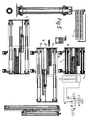
- FIG. 11 shows in a vertical section at the top left, to the right in elevation and below in longitudinal section, the functional stages A and B of a vehicle variant to that shown in FIG.
- the scale is 1:40.
- the telescopically extendable articulation column (4) was laid between the two towing vehicles (14,16).
- the outer frame (17) provides the connection between the outer tube of the telescopic columns and the towing vehicle (14).
- the motor vehicle (16) and the cabin (21) are the functional unit via the inner frame and its connection to the upper end of the inner tube of the telescopic columns. Between the motor vehicle (16) and the cabin are the hinge joints (24) of the attachment.
- the towing vehicle (16) was shown on the right side of the plan in an angled position as on a track curve. It is apparent from the task to restore the straightness of the entire vehicle axle before a rail change.
- the task was solved by the cables (10,11) with intermediate tension springs between the motor vehicle 14 and 16 (end) and by the spring-loaded tongue in the spring-loaded detent switch (26), which fixes the vehicle in the extended position.
- FIG. 12 shows a further variant of the vehicle type on the right, as in FIG. 11 above in a top view and below in two longitudinal sections in two functional stages A and B, which differs mainly from the previously described embodiments in that the motor carriages (14) are connected to the vehicle Cabin were combined on the outer frame and are lifted with the outer tube of the telescopic column (stage A), while the motor car (16) are raised with the inner frame through the inner tube of the telescopic column (stage B) and lowered.
- the telescope column was set accordingly to 180 degrees on the "top". The loads appear so cheaper distributed on the wheels.
- the detailed sketches in the lower left corner represent two solution variants A and B for a track change in curves. It may, for example, be a vehicle according to FIG. 11, in which the motor vehicle (16) is connected to the motor vehicle (14) via the articulation column (4). From the joint column, the drawbar (6) leads to the pivot axis (9), around which the motor vehicle (16) can be rotated. Joint column and pivot axis are about stepper motors or other drives - in the cables (10,11) in Figure 11 top right, the springs could be replaced, for example, by a pair of hydraulic pumps - angle controllable rotatable.
- the detector (12) which is designed here as a metal finder but could also work according to other principles, is present here fourfold.
- At least two detectors report rail proximity for a stop command.
- the motor vehicle (16) can be equipped with one or two motor axles (not shown).
- the slow pivoting of the drawbar may be accompanied by rapid oscillations about the pivoting axis of the motorcar and stopped with the correct placement of the wheels over the rails.
- the small square above the drawbar denotes an electrical contact which is mounted to coincide with that (drawn as inner square) in the middle of the trailing edge of the motor vehicle. This contact closure may be used for precise alignment of the drawbar in its pivot axis in cooperation with the computer.
- Correct axis alignment between the motor vehicles by means of the stepper motor of the articulation column 4 can also be achieved by radiation detector bearing, as shown below in variant B with the dashed line opposite the small hexagon, which indicates the reflection of a measuring beam of a radiation detector (and producer) a mark on the back of the previous motor car - which is shown here, however, lifted up - symbolizes in evaluation and calculation in the computer (as shown above).
- the merging of the central projection axes of the rotatable carriage parts is of special importance if the preceding motor vehicle outline (dash-dotted line in variant B) does not at the same time also determine the alignment of the motor axes.
- the towing vehicle (14) has at least one detector (329), which, working on the reflection principle, scans a selected arcuate area in front of the towing vehicle for contact with a rail by means of preprogrammed oscillating motion.
- the calculated in the (not shown) Calculator rail position and thus curvature is transmitted to the above already to A described pivot motors.
- the alignment of a neighboring motor vehicle can be accomplished on a neighboring track. This becomes clear on the horizontal section below, on which the towing vehicle to be steered in the swivel angle is raised.
- the detector could also make an additional scan in the direction of travel over a very specific distance, thus allowing the track curvature to be calculated.
- the telescopic column can also be mounted between the two motorcars (16,14), wherein the motor vehicle (16) are connected by the outer frame with the outer tube of the telescopic column and the motor car (14) and the cabin with the inner frame and the inner Tube of the telescope column (no longer recorded, see Fig.15 the small plan view).
- FIG. 13 shows, in partial vertical sections on a scale of 1:40, schematized to the utmost, from below the middle left to bottom right to the top left on a two-stage palisade, the functional partial steps A to G of the ascent of such Climbing machine according to the Fig.1, 11 or 12 again.
- stage D temporarily (in stage D), the carriages of all four motor vehicles must be extended horizontally.
- a multi-level palisade (62) there are two vehicles in different climbing positions, the topmost resembling the stadium E below, the lower one with the stadium C below, but the upper one with hanging cabin (21).
- the elevation of a suitable for such an application vehicle variant is shown in the scale 1: 80 left.
- the telescopic column (3) takes over the function of the joint column between the motor vehicle (14) and (16), the last is rigidly connected to the cabin. It will be appreciated that with such deployment in hanger position, twice the height would be required per vehicle.
- the hanging version was therefore further developed with Fig.16 and following Right on the multi-level palisade, two vehicles were drawn one above the other. On the left are tilting positions of one of their motor units.
- the three vehicles in the left center roll on rail sleepers (73) with drainage ditches (74) between them.
- the step pattern of a vehicle ascent according to type Fig.1 or 11 begins in the basic position A with wheel contact of all components on the same two track rails and ends at the top left with G, where the towing cars (14) together with the cabin were pulled up onto the new gels. Opposite the lower rung is at F a counter-pillar with a track-carrying rung for purposes of switching to a parallel track. To the left of G there is also a counter-column, which carries two sidewalks (75) for entry and exit into the cabins on different floors, the sliding grids (76) of which are interlocked with each other, except when a cabin fills the gap (see also Top view below).
- FIG. 14 shows a top view 1:40 scale plan view of a vehicle with stalk legs whose wheels and axles are extended fore and aft on the same track and upright by a fluidic swing motor (pneumatic or hydraulic) as an auxiliary motor (50) Allow the vehicle to approach the vertical position (stage B center, left in the longitudinal direction, right in vertical section C) and above the height of the next higher track.
- the carriage (5) functionally corresponding swivel arms are also equipped with swivel motors (rotors), all with limited swivel range (icon to the far right), which, however, do not work as in the vertical axis, but in the horizontal as the Stelzbeinrotoren.
- stage C of the swivel arm rotated to the next higher track the slide channel (64, see C below) is laid in the longitudinal direction. (It could also be avoided by a telescopic construction of the swivel arm.)
- a frame groove guide engages the cross pin of the end of a swivel arm, depending on the pivoting direction so shortened or extended sideways out of the vehicle floor plan.
- the cross-section D shows how the vehicle is last used in the projected two stages in the course of the grätenden return movement of the pivot arms to the higher track. It is not shown that the Stelzbeine naturally raised slightly up to their lowering onto the new track by their rotor.
- the figure 15 shows right in a cross section, left in a longitudinal section on a scale of 1:40 schematically a device in two functional stages A and B, which serves the track change of a suspension vehicle, which runs on two rails of a track. Lifting and carriage movement are combined in a single movement. It prefigures the idea in Fig.17,18. Each "towing vehicle” is supported by two bow arms, at the end points of which swivel motors with limited swivel range are located (see symbol). On the longitudinal section below, six such motorcars were drawn; if two were used, one would choose the middle one, it could be more.
- FIG. 16 shows in the vertical section on the top left, on a scale of 1:40, a suspension vehicle similar to that of FIG. 15, but with a cabin extending over two parallel tracks and their ascent to a higher track.
- a suspension vehicle similar to that of FIG. 15, but with a cabin extending over two parallel tracks and their ascent to a higher track.
- the synchronized in working arms with swivel motors were moved over retaining bars laterally outside the cabins.
- Such an extension on even more rails, if intended, is of course possible and, in principle, can also be transferred to vehicles on track.
- wheels and engine complexes were also drawn on stanchions, which could be of particular importance for hanging cabins when the tracks are laid at ground level continue.
- the power supply could also be done by the motors above analogous to Fig.33 bottom left.
- the necessary tools such as motor car leave out of the previously easily derived.
- level D two narrow normal cabins are shown side by side.
- the cabin height will be set up so that a track change between the outer and inner track is possible.
- the balconies can also be supported (see C) and the wide cabins can be divided into two halves to normal cabins during the changeover to other tracks and possibly also moved one behind the other (not shown).
- FIG. 17 is for a suspended version of the invention.
- a side view of a hanging cabin and top right on a scale of 1: 20 a hanging cabin for the post and parcel service enlarged as a detail.
- stage B the left half after reaching the telescope tube to the next higher track.
- the longitudinal detail of one of the paired telescopic handlebar ends with the motor drive in two stages of operation.
- the enlarged detail of a booth for mail and parcel conveyance uses, for example, a suspended T-bar (84) with rollers driven by the motor (1) on its T-bar.
- the transmission for power transmission from the motor axis to the roller axes was only indicated by bevel gears.
- the small detail elevation at the top right shows that the bearing for both wheels (102) above the vehicle cab is rotatable about the hinge axis of the inner telescopic tube (8).
- Swivel axles (85) are used for the lateral deflection movement of the telescopic column (3) of the motor vehicle (14) - we want to keep the name for comparison - and the support arm of the motor vehicle (16).
- the frame (17) is reinforced by the (middle) inner frame (18) which, like the lower one (17), is interrupted by the hinge joints which take over the function of the articulated column (4) in Fig. 1, so that the motor vehicles ( 14,16) are mutually laterally pivotable and adapt to track curves.
- the partial longitudinal section B on the right shows the telescopic column extended and in the seat on the next higher track rails.
- a motor vehicle (14) is described in detail.
- the mother shifts and approaches the right wheel of the rail (22) from stage A to stage B.
- the vehicle must overhang to the right to support against the upper rail (23).
- the power transmission to the wheels via the drive belt (86) from the engine (1); the circulation pump (15) for raising the (not shown) telescopic rod is below.
- a variant of the vehicle which manages with two motorcars, one each of the type (14) and (16) by the wheel axles (in turn rotatable about their support tubes) extend gallows over the car roof and approach each other.
- the traction cable (87) extends from the wheel axle on the carrier arm to the right end of the car roof.
- the further tether (88) is unwound to the extent of the cable drum or reel (30) as the telescopic column, at the outer edge of which it is attached. rises, what happens via a functional coupling movement (similar to in Fig. 3)
- the cabin is kept in the horizontal, even if one of the motor car leaves a track.
- FIG. 18 shows a variant of the suspended vehicle of FIG. 17 using a single track rail per route.
- a motor car (14) the A stage of hanging in track contact A and the stage B of reaching out to the next rail, right enlarged details of the engine unit.
- stage A the pivot mechanism of the telescopic column is shown.
- the threaded spindle moves by rotation of an only indicated motor with gear below a threaded sleeve, which engage via hooks in slots of guide blades (dashed lines 89) (shown above in enlarged detail).
- stage B the outer telescopic tube displaceable around a rod in the pivot axis (90) was thus pivoted to the right.
- stage A the lateral support or support wheels are swung out around a respective axis of rotation, while the drive wheel rests on the rail on the axis of the motor (1).
- stage B the angle arms were loaded in continuation of the Stauerradachsen, which is symbolized by the lowering of the pulled around an axis rotatable short pipe sockets (92) rod.
- FIG. 19 gives an example of a runner vehicle for linear motor drive in the form of a stand on two track rails. Above the stages A - C of an ascent from the lower to the middle rail in the partial longitudinal section (the right mirrored halves of the arcades have been omitted). Right in the middle a plan view and above a vertical section in the scale 1: 80 with respect to the larger representation deviating variant of only two, but elliptical telescopic columns (3) with the carriage extended two runners. Below is the enlarged and slightly detailed reproduction in scale just over 1:30.
- the skids (93, 94) are shown as U-shaped rail comprehensive, without going into the problem of magnet assembly and control in more detail
- the lower left rail is continued a bit and then omitted.
- a fourth raised runner can also be carried (not shown). If the lower runners are provided with a lifting device, the higher runner does not require any (here no hydraulic pumps in the sled balcony (95), as they are required for the illustrated raised runner). The slide displacement is done hydraulically by double pumps (see Fig.5). For rail curves, the runners are elastically flexible.
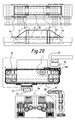
- FIG. 20 shows, on a scale of 1:40, an example of two rail skids (93, 94) which can be transported sideways or upwards via a tracked track, at the top in a plan view, including a side view to demonstrate that the skids are also nested one above the other could be.
- the movement mechanism for the rail skids is illustrated in the middle longitudinal section, below in a 1:20 scale section with enlarged chain details to the right.
- the enlarged cross-section in the center shows a tracked track (96) steered by the four gears (97) and driven by a gear on the motor (1).
- the two track runners (93, 94) are held on the chain track by struts and cables on the endless track and taken along by them when moving. The amount of movement is indicated by an accompanying dot-dashed outline.
- Each two (guide) gears are held by struts that leak in the chain support (98). From the cross-section it is clear that in addition to the carriage control to the right and such can be done to the left.
- the longitudinal section, below, by the towing vehicle in the amount of hydraulic piston shows how the latter are embedded between the tracks and the skids are used lifting and under an expanding receptacle (100) for the blade causes electrical contact closure.
- FIG. 21 shows at the top in longitudinal section details on a scale of 1:40 the functional stages A and B of the descent of a rail scooter vehicle from a higher to a lower rail track.
- the mechanism of pivoting a support wheel is explained. It should be noted here that the two runners must hang on different, separately driven tracked wheels, and that the car and the total load must be shifted more outwards for this rail arrangement is appropriate; for an extension of the carriage in both directions, the cabin would even be moved to the outside in each case.
- the mechanism for swiveling in a jockey wheel can be seen from the A stage.
- the swivel arm (54) with the support wheel (25) is pushed back around its axis to the left. This is effected via the auxiliary motor (50), which can set in motion a cable circuit via the deflection rollers (103, 104), which are also articulated axles. This is illustrated by the motor vehicle (16) in the upper right in the stage (A) of the support wheel hammered onto the track rail (23).
- the use of the telescopic columns (3) and the carriage (5) corresponds to that in FIGS. 1 and 2.
- stage A the runners of the motor vehicle are first lowered under rail (23) and rolled over the track to the right; then the motorcars could be extended through the sled and lowered over the telescopic columns. They are already on the lower level again approximated to the track carrier, so that the left runner can be lowered onto the rail (22).
- stage B is the right skid rolled under the rail (23) and must then be raised before the cab can be made up with their caterpillars.
- a safety rope catching device is shown below A and B in longitudinal section.
- the safety cable (149) may be attached to a cabin but also to an individual airbag and leads to the pivot arm (150) which communicates with the bracket (151).
- Whose ends are connected by hinge joints with the pliers arms (152) which surround the elliptical band (153) that is tied to the top of the strap and suspended on this spring and passes with protruding tabs through slots in the forceps arms.
- the device is held by the swivel arm in a grommet on the cab (21) suspended above the carrying cable.
- the swing arm In the fall, the swing arm is pulled out of the grommet and is exerted by the safety rope train, the elliptical band falls down on the support cable and is pressed upwards over the hinge joint against the pliers arms, which are spread apart and close down (stage B).
- stage B The ends of the pliers arms are barbed, which are verrastern.
- a blasting cartridge to break off the rope is activated in the extension of an intermediate tension spring with control unit (rectangle), if not there at the same time there is normal wheel contact of the vehicle with the rails wirelessly reported.
- the brake (128) on the cable drum is then actuated.
- the telescopic guide of the swivel arm can be appropriately controlled and driven to compensate for fluctuations in the rope height.
- FIG. 22 explains the functional sequence in the transport of persons and notes striking examples with detailed information from the figures discussed. Above all, control operations are mentioned, as they are then further summarized in Fig.23 and Fig.24. In the left column, a vehicle cross section is indicated in the associated stages of the boost A - E of FIG.
- the vibration sensor (105) is symbolized by the current closing by the swinging of a metal tongue loaded with a ball.
- a corresponding contact closure causes the insertion of a U-shaped bolt (38) in the cabin attachment to the frame (Fig.11), which just has to be completed by further pushing the bolt.
- the spring sliding tongue (106) on the pump tappet as Lock switch the correct seat by contact closure for the current flow. Since the two track rails (22,23) serve as a current conductor, the correct seating of the wheels can be measured on them during the power take-off ( Figure 11)
- the telescopic rod (110) On the car roof (Fig.2, left in vertical section) is on a pivot along the crossbar (107) with battery-powered stepper motor (small ring on the longitudinal section detail top left) the telescopic rod (110) extended and seizes electrical power from the next higher rail if the cabin is on the lowest ground level track. Access to the track rail is from below through funnels in the protective grid.
- the enlarged detail on the top right in the longitudinal section indicates with the small circle an optical sensor in the area of the telescopic rod which laterally moves the swivel joint by means of the stepper motor along the crossbar when it comes to rest in front of a pillar (dashed rectangle), which is from the sensor is reported to a computer (see Fig.23, below) and evaluated.
- the distances when extending the telescopic column ( Figure 3) or the hydraulic pump combination ( Figure 9) for raising vehicle parts can be registered by scanning of measuring marks (111) by the sensor head (112) and in the on-board computer as inner control unit (113) for sequencing are processed.
- the corresponding data are also sent to the higher-level control center as an external control unit (114), which determines the autonomous control options and their influencing options by the passenger.
- an external control unit (114) determines the autonomous control options and their influencing options by the passenger.
- a branching on the control transformers for the separate control of the motors (1) for the vehicle drive (142) and for the lifting and moving movements (143) via pneumatic, hydraulic or electric drive (144) in the field of motor vehicle see also Figure 23).
- Fig.6 For lateral displacement of the carriage Fig.6 is used via a spindle drive with the alternative of a hydraulic pump application according to Figure 8, for tilting the motor axis in addition to Figure 12, wherein the impact of the auxiliary wheel (25) by (not shown) electrical contact closure approximately according to the position of the pivot arm (54) is checked. Measuring marks are located (111) along the gate for the swivel arm.
- Fig.8 solves the problem with hydraulic Pumps, the plunger (not shown) wear measuring marks for sensing by a sensor or can easily cause contact shifts when passing., Which are reported back to the computer for function control.
- the sensing of the effective distances can - also in other tasks - be done by simple current contact closure with markers, but also with any more sophisticated technology to the use of optical position sensors using position diodes (Position Sensitive Device, PSD) or the use of removal bearings.
- PSD Position Sensitive Device
- the contact closure between the lowered half-shells 68 and the pump cylinder (only half shown) indicates the correct position of the motor assembly 20.
- the contact closure between the receptacle 100 and the rail runner is in current connection with the rail as a measuring criterion
- the symbolism of the measuring circuit with the interposition of the measuring device (115), which stands for the sequential control, is shown above it.
- the collection of the fetched motor car on the new track corresponds to a reversal of the processes in disposition 7.
- the top view detail in the middle at the bottom can be seen in the cabin lock with the vehicle frame their equipment with two blasting cartridges (116), one of which is shown enlarged on the left.
- the black circle indicates nozzles on the bolt (the corresponding slots for the introduction of the same have been omitted) on which the blasting cartridges are mounted with their piston closure.
- the booster rocket (118) causes the car to be disconnected from the rest of the vehicle. This is done automatically via the on-board computer and control unit even before the cable drum is loaded to the maximum with the brake.
- FIG. 23 gives, with reference to FIG. 11, a vehicle outline a circuit layout plan.
- the oil circuit starts at the pump (15) via a switching throttle (164) after reflux control in the slide valve, which is controlled by the magnetic switch (165) from the electronic drive train (right side) ago. Reflux into the tank (166) from the return line is prevented by the check valve (167).
- the inflow port has a dirt filter and the slip loss is offset by displacement to the left of a Druckgasposter ago free of air.
- the discharge pipes from the spool valve are continued as strokes which reciprocally supply the double-acting pistons below.
- Backflow-controlled check valves (168) in the criss-cross let the pistons stop at any height without Lastfluß and hold in position.
- the two upright pistons are used for lifting vehicle parts, the transverse ones below for the sideways movement of the carriages. (Instead of the two pumps, there are two pairs of each in most examples.)
- At the bottom is a circuit diagram that divides the gate valve into the functionally appropriate two levels.
- the text on the electrical system on the right was to be supplemented by the scheme of modular networking.
- FIG. 24 gives an overview of the relationship between control centers for the central control of the overall traffic system, with reference to two adjacent 1 and 2, and to the cabin or the entire vehicle.
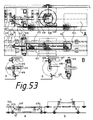
- FIG. 1: 160 The treatment of freight traffic begins with FIG. At the top left in the functional stage A in longitudinal section on a scale of 1:40 a cargo cabin (119) is shown, which is hanging equipped with two snowmobiles, which engage at different track height.
- the analogue bevel gear drive in the tilting axis (120) in the middle on a scale of 1:20 is explained more clearly, the function of a slanting of a four-lane load cabin during the transition from the elevation to level tracks, combined in a vertical and longitudinal section, dealt with in the figure below ,
- vertical section scale 1: 160 two stages (A, B) of the tilting of a cargo cabin were inserted on two tracks, in which the wheel axles are aligned horizontally by pivot motors mounted on the cab (shown as rings); it can be seen that the here telescopically equipped wheel axles are pulled out in the transverse direction.
- the dash-dotted outline cargo cabin (119) is equipped with a trapezoidal designed and about the tilting axis (120) rotatable container (121).
- left gear (122) is indicated for a bevel gear in the tilting axis with representation of the required clutch, including analog and enlarged explained.
- the stationary pair of rollers is mounted on the slide for the upper motor with a pivot. (The tilting mechanism for placing the wheels with the motor shaft moved has been omitted here, as previously discussed extensively.)
- the lower motor hangs on the carrier rail (125), at the left end of which the tilt axis is attached.
- the auxiliary cable (127) when pulling up the roller carriage.
- stage B top right, it is open and the auxiliary rope is on the ground.
- the cable drum with brake (128), to raise the cable drum can be coupled to the motor (1).
- the stadiums A - D are intended to illustrate that with stable rail position by load application from above in the vertical to the wheel axle fixed mounted rods can interact via sliding cuffs on a connecting rod.
- the sliding sleeves must have a pivot for the rods, which in turn can be pushed through them. Screws under the sliding sleeves were brought down in steps on the sketch; without this correction, the frame for the cargo would have arrived in the plane higher than on stilts.
- a simpler solution is the fixation of the pivot joints in the amount of A (vertical sliding joints and screws then omitted) and the involvement of the connecting rod under its duplication in the load-bearing body structure, ie higher in the load cabin best by doubling and shifting to the side walls ( Longitudinal section left outside).
- the crossbars between the sliding sleeves could be laid under the car roof, also the rods fixed on the axles could be doubled and moved close to the side walls.
- brakes symbolized only in places by wedges or triangles
- Such a brake is down in enlarged detail scale 1: 20 using a rack with gear and pawl - it could of course be another brake - outlined.
- the brakes can be spared if separate load containers are each connected to the rods fixedly mounted on the axles according to FIG. 26 top left. (Only one such load container was at A and left of it in Longitudinal section drawn.) With heavier tilting of the spar, an axle load distribution would have to be applied to the connecting rods to the wheel axles (see cylinder-piston symbol).
- a freight vehicle type is presented in a longitudinal section on a scale of 1:80, covering the steel arch arcades (133), which are supported on four landings each with two track rails, in a saddle-like manner by means of the frame framework (134).
- the latter is carried on the track levels 2-4 of motor vehicles on both sides of the arcade central axis and leaves above two passages, on the rails of two passenger cabins (21) are shown, which move independently.
- the freight cabins are hatched.
- Also left side on the stanchion is a passenger vehicle.
- the arched arches are specially reinforced to withstand increased pressure associated with the lower track rails (see Fig. 30).
- FIG. 26 shows at the top left of each other two foursome combinations of freight cars, as shown below in FIG. however, they are here, shown in longitudinal section, pushed together in one plane.
- One of the slide hinges (119) is highlighted in detail on the right.
- the upper cargo cabin variant has crosswise bracing; in the lower cargo cabin variant, the outer frame that encloses the container (121) is reinforced.
- In the upper right is an interrupted track section with two thresholds or steps (of pillars) in plan view at a scale of 1:20 in the sections A and B. It will be demonstrated the transition from a height-different rail guide in such a side by side. In the latter, ie on the lower track section B, the motor axis is centered in the vehicle, which requires more space to the pillar.
- the inner higher track rail must be performed until its elimination to longer arm, which makes stronger angle support to the pillar (175) out necessary as well as a widening of the pillar along the track or a pillar accumulation in the rail transition area.
- the lateral suspension of the inner rail in the pillar area can make a rail increase necessary to ensure the stability of breakage. If a support wheel (25) is operated on top of the rail, the support wheel axis must be raised relative to the cabin over this type of climbing switch.
- this is demonstrated by an eccentric axis guide, wherein the mechanism for Derrismung the eccentric disc (136), because technically known, was not shown.
- the transitional stage to the other rail type can also be seen in the illustration below in the vertical section stage A. There the moment was reproduced, in which three track rails are present, before the higher one falls into omission.
- the shortening right corresponds to an extension of a pull cable between the sliding sleeve and the fork (145) on the left side.
- the cargo cabin describes a tilting movement, as it is the changed angular position of the connecting rod to the motor axis in stage B expressed.
- the cables have been replaced and symbolized by mutually intersecting rods (147), which can effect the vertical alignment of the wheel axle with the distance ratios of the rotatable rod end and fixed points selected.
- Articulated rod end points can also be attached to the spar (137) without a connecting rod (138). Analog to the rope replacement Fig.14 should be used top right.
- the pyramid over it in the scale 1 160 shows how with uniform decrease in height of the pillar steps by 20 per cent (representation cleared off before the zero line) the connecting lines of the step corner points are lowered. On the left side, an opposite line elevation is sketched, omitting the steps.
- each wheel axle has at its outer end fixed gallows, about the hinge joints of the top beams are pivotable. On this shifted approximately to the outer walls of the load beam beams rest on the container fixed mounted oblique rails.
- the second tilted bar contour corresponds to a lowering of the track level (dashed double contour) from stage A to B (see left).
- the hydraulic piston in conjunction with a sliding gallows foot to illustrate the possibility to regulate the load distribution on the various axles under measurement monitoring here.
- the figure 27 is to show with the combination of two track sarkades in vertical section on a scale of 1:80 that heavy and bulky loads can be transported even with low pillar constructions.
- the vehicle units 1-3, 6-8, 9-11 and 14-16 have been presented in dash-dotted outline as a possible unitary freight transport vehicle.
- the dashed outline of the cab should show the possibility of transferring passenger vehicles from one arcade leg to the other. In this way, tracks for rising average speeds can also be arranged descending and low-lying.
- the rectangle for a freight cabin (119) laid out above both arches shows that bulky goods can also be transported in this way.
- the function of a rotatable switch is presented in a vertical section through a double track, including in elevations scale 1: 40 in the two stages A and B, to make in the same track height in the pillar area a Schienenalede Trent.
- the track segment (154) by rotation about the pivot column (155) attached to the pillar of the additional track created (stage B), which is also possible with different height rails.
- stage B the additional track created (stage B)
- the vertical section details below illustrate that two platforms or girders are needed, the second of which, with the tube (156), must be lifted around the pivot below the rail (22); the small side view on the left refers to the slot through which said rail can pass.
- the upper rail may be pivoted across rails by the rail support (157) (dashed line).
- the cargo cabin (119) is here two hanging Motorcar on the lower track and is carried on rope and pulley (31) by a chain of suspension lorries on the higher track.
- the length of the chain is limited by the compressive strength of the connecting frame (177), which is subject to compression.
- the train connection extends between the upper (177) and lower (17) frames. The consideration and distribution of the load on the different motor axles is shown in FIG.
- a pivoting lever protrudes from its hinge joint on the underside of the car obliquely back down; at the end it has a fork, which includes the end of the upwardly spring-back axle of a support wheel close to the same and pushes up as soon as and as long as an obstacle between the track rails, abuts against the pivot lever and displaces it;
- extendable bollards (178) were provided in the switch area.
- This motion pulse can also be stored in a compression spring (not shown).
- the wheel axle can adjust to the rail bend angle at the beginning of the turn curve before it is fixed by the plunger until the pivot lever lowers behind the bollard again. If both plungers are actuated at the same time, then no Radachsenburnung can take place and the vehicle can continue driving on appropriately set switch with fixed axle straight. When extended to the rail contact support wheels get this constantly adjusting the Radachsenwinkel ein the rail curve .. In the area of the handlebars, the additional inner track rails represent, the pivot lever remains the support wheels by a board-like bank (dashed) off or raised by electronic control (see below).
- the device can also be used outside a turnout passage; as well as Abschwenkvorlegien for support wheels can be coupled to the radar device.
- FIG. 28 shows at the top in two schematic longitudinal sections, on a scale of 1: 160 hanging vehicles on ropes, one of which is shown in stages A and B in relation to the distance from the last pillar; including the reduction of rope sag using an upper tether.
- the detail of a vehicle is offered, in which the height compensation is achieved by a lifting device on the cabin.
- the top schematic longitudinal section to demonstrate by sketching of three hanging vehicles simplified illustrated that the rope sag by means of vertical movement can be compensated so far in the vehicle suspension about the telescopic column actuation that the passengers continue to move in the horizontal.
- the detail of the vehicle in the middle below shows that the vertical movement between the towing vehicle and the cab (21) on the frame can be compensated, for example by piston stroke (pump oversized here).
- the control of the height compensation of the cabin can be done in very different ways.
- the angle between the telescopic column and the connecting beam of the wheels lying on the supporting rope can be evaluated by calculation. But there are also height measurements or horizontal bearings in question.
- the changed force when passing the rope sag is compensated by the on-board computer to a uniform speed.
- the small cross-sectional detail on the right under the upper rope is intended to demonstrate the use of top and bottom rail on the rope, for which a rod connection with end hook between the height-different ropes appears expedient.
- the row under the suspension ropes deals with the possibility of a track rail for linear motor drive suspended from two integrated suspension ropes (22, 23) in addition to other auxiliary ropes in cross section, which rests on a runner (93, see Fig. 19) on a scale of 1:20.
- the cast-in solenoid coils were also sketched laterally and downwards and could with the drawn with a Einschwenkarm counter skid for the modulation of the serve necessary gap.
- the upper runner is shown in longitudinal section, as it clings to the rope slack thanks to its elasticity.
- This Gegenkufe is divided again and therefore has a (only shown with his approach) second arm.
- the suspension of such a rail with a double rope core is presented; the cut is guided by the ascending arm of a T-rail, as shown on the right side in another vertical section through rail and runner in stage B of the passage on a rail suspension.
- the wedge on the rail profile namely pushes the elastic track rail apart laterally, so that it evades the rail bracket, which is favored at this by a series of lateral rollers.
- Stage A on the left shows the mechanism in the off state and the state B on the right when switched on.
- the two outer pivot arms (186) extend from the foremost and rearmost towing vehicle and carry spur wheels, which act from the side on each of the support cables.
- the bow (187) is approached via the cable from the winch (188) against the compression springs (189) the motor car and urges with its slopes the spurs on the pivot arms respectively from the outside against the suspension cables.
- Spur extends at slit-like transversely displaceable mounting of the cross member (190) having a pivotable in its center about its vertical axis balance beam (191) whose ends carry inner mating wheels, which press horizontally from the inside against the support cables when the outer Spurrad on the trolley of the cable over a roller bearing at the middle of the bow is brought to the winch.
- the Compression spring (192) brings the spurs back from the suspension ropes. In track curves that are performed on rails, the horizontal wheel guide is turned off.
- the figure 29 shows below in vertical section on a scale of 1:40 stadiums A and B of the transport of a caravan on two different height tracks.
- Stage B shows the left shift of the roof box to make the symmetry and the lowering of the pneumatic tires (199) of the caravan for the rail-independent propulsion by engine coupling.
- Figure 30 addresses the problem of train overload protection for the tracks and motor axles. Left is shown in longitudinal section on a scale 1:10 a shortened pulley, as it can be used according to Fig.27 (below) between freight cars and motor vehicles on different tracks in conjunction with each other by load redistribution in particular on the near-ground track. On the right hand side, the problem of the pressure load for a stand vehicle was treated accordingly.
- the upper outer wheel of the pulley (31) and the rod end of Verstellschlittens (203) are attached to the upper frame (204) and thus also the free end of the cable.
- the large pulley bottom is connected to the lower frame (17) of the truck, both frames indicated only by dashed lines.
- the adjustment slide includes a stepper motor as an auxiliary motor (50), which drives a spindle via a gear, which can move the mounting rod longitudinally and thus change the length of the pulley.
- the stretch mark (205) serves as a measurement indicator for borderline tensile load and sends measurement signals to the computer (dashed line), which in turn sends command signals to the stepper motor.
- the cable loop (206) bridges the cable area around the tension spring (207) in the slotted cylinder and protects against strain on the expansion strip.
- the cable drum with brake (128) and stepper motor is used for rope extension. The latter instrument can be conveniently moved to the long Switzerlandseilende and become and replace the function of the Verstellschlittens in cooperation with the stretch marks. (This alternative was discontinued because it is self-explanatory.)
- the analogue solution on the right for a towing vehicle, which stands on track rails, bottom right also provides in longitudinal section and scale 1: 10 before a load compensation, this time a hydraulic.
- throttle valve (208) obstructs under load of the attached to the hydraulic cylinders frame (17) the flow of oil from the large into the small cylinder while lowering even the small piston against a strong compression spring only as long as the pressure from the Piezoelectric element (209), embedded in substance task-appropriate elasticity, the computer allow this to program.
- the throttle valve is opened, thus shifting load to other engine axles and rails (see Fig. 27 below). It is easy to see that the two balancing mechanisms - once for Tensile, then compressive load - can represent each other for each task solution, if appropriate impact redirections, such as ropes with rollers or levers are made.
- the figure brings in the third row from above vertical sections through palisades as track carrier as already treated in Fig.15 but in variations on a scale of 1:40, at the bottom left again in vertical section on a scale of 1: 80 a kind of railroad track as at ground level in Figure 13 below the small plan view, elevated here on palisades, right next to a kind of ejection seat with airbag is shown.
- On the left in the second row from the top the possibility of a vehicle being shown to cross from one stockade track to another different in height, which lies opposite the stockade, is demonstrated. The vehicle is still in contact with both tracks with its motor vehicles.
- the illustration on the right shows that the same track level can be crossed, outside the palisade pillar itself on the left track.
- FIG. 13 As shown at the very bottom left in the vertical section, what is described on FIG. 13 under the small plan view for ground-level deployment may also take place on higher track floors when using stockade.
- a track floor without intermediate columns can be used for the transport of goods, for example for the supply of department stores, in our case by track deflection to the right outside into upper floors.
- Right in the middle is indicated with elevated track, as well as a single-rail passenger vehicle by means of a rail curve - for example, following the deflection of the inner railways for freight - could change without climbing right to the right.
- FIG. 32 shows schematically in the vertical section on the left in the scale 1: 160 a type of track bench, a bridge with horizontally adjacent tracks on the second track level; including in a cross-section scale 1: 2, as a toy a mounting clamp (219), the corresponding plan view below it in the scale 1: 4; it follows below the associated wire hanger as a rail carrier in longitudinal section and scale 1: 8; at the bottom left it is about a mounted from below track bracket, otherwise the invention is once again parked with the toy model construction and indeed with possible plastic pillars as rail carriers., Can be dismantled for a kit.
- the schematic vertical section at the top left shows a kind of track bench with the effect of a threshold broadening with supports instead of a railway embankment.
- a threshold broadening with supports instead of a railway embankment.
- In the middle of a track segment is lowered as a switch from a higher elevated to a lower track (shown as dashed lines, see Fig.29 center) ..
- dashed lines see Fig.29 center
- the mounting clamp (219) which can be seen in a cross section and a reduced plan view, is used to connect the wire hanger as a track carrier with each other by means of cord or wire with end eyelets.
- the latter can be hooked into the hooks, which are screwed into the bent plate of the mounting clamps and allow the connection of adjacent wire hanger.
- the last wire brackets must each be attached to fixed points in order to stabilize the carrier ensemble.
- stair, knee and extensible piece Predominantly in vertical section are shown top left as components stair, knee and extensible piece as components of a four-sided built pillar in scale 1: 3 and shown mated in the middle.
- the steps have depressions (see small detail arch wire top left) and / or projections to secure the exact lateral distances of the laid rails.
- the connecting sleeve (220) between the bottom step and the baseboard is shown in the center left.
- the ascending leg of the stairway piece has fastening strips for an additional rail or a rope; at the back there is a studded pencil (221), which facilitates the connection of rails (for example also by means of loop-shaped rubber small) and can also be kept smaller.
- Cross sections are given below the staircase on the left.
- Edge strips (222) on the respective outer fitting piece with window allow engagement of the elastic tongue of the inserted part beyond the edge of the window without, for example, standing against a floor rest.
- the recording wedges (223) may have with or without spring sliding tongues for the vertical struts and are mutually releasably grouted.
- the use also overlaps Plates in question, which are connected to each other in the manner of a push button (224), as shown as variant B.
- the lamella ((226) which extends along the tongue underside through the gap in a wedge shape downwards.
- the bottom left shows the core of a (shortened at the fault lines) mold for producing a bellows; the enclosing shapes are inherent in its design and are not shown, except in an intimation of the annular groove (227).
- It can be made of suitable materials, such as Bunan or PVC, in one piece, the supply hose on the left with an annular groove for the insertion of a mounting bracket and at the end of a projecting flange (228); the assembly is much easier, as shown by the hatched wall parts and the bolted mounting ring at the right end. (The ring groove was drawn out enlarged above.)
- the first (A) is locked from below, the lower second (B) screwed together by means of a key through a hole (elbow).
- Supporting cables as in the case of a suspension bridge (see Fig. 28), can be used, but restrict the track change by the vehicles.
- FIG. 33 at the top right, the lateral orientation of the pivotable motor vehicle when changing rails, bottom left general building features. Top right is explained in elevation details, analogous to Fig.12 bottom left, in the stages A and B, the orientation of a motor vehicle over a rail turn.
- the straight direction of the vehicle axle to exclusively change track on straight stretches can be done either by a tab (231) made of stretched elastic material with tendency to stretch, which is attached on the left, on the towing vehicle right but under the loop (232) is displaced and thus constantly strives for straight line , Below meets the tension spring between the articulated vehicle parts the same task.
- Figure 34 was used to complement the task solution with simplified instruments and components mainly for toy manufacture.
- the middle line begins with a perspective view obliquely from the side on a simplified model of a motor car body model.
- Structurally characteristic of the invention are the lack of a bottom part (109) on the housing or at least a wide open at least one side slot for the displacement of wheels and motor axis and the at least partially lack of at least one side wall (234) as a passage for a motor vehicle the carriage (5).
- the camouflage as already known and common model vehicle by screwing or releasable sticking of floor or wall parts, which are intended for removal, should be considered a patent infringement.
- the specification of predetermined breaking and sawing lines for such a distance also using templates and instructions.
- a vertical section shows a vehicle model on a track (22,23) with two types of support wheels (only one version is required).
- the right support wheel makes use of a continuous third upper and inner rail, which may also be a rope, and is located in the stage A of the elimination;
- the lower support wheel is located in lateral engagement on rail (23), ie in the stage B.
- the pivoting of the support wheel during the one-sided external load when changing to another track is caused by current loading of the respective electromagnet (230) - here with repulsion of the poles - while the return of the stop-limited pivoting movement for the support arm of the support wheel is effected about its axis by a small compression spring.
- the horizontal dashed line (sketch far right), which establishes a rigid connection between the motor shaft and support wheel, stands for a preferred solution in toy model construction, to avoid the electromagnetic pivot mechanism and only the tilting movement of the vehicle by unilateral load after leaving the original track Use the connection of the support wheel.
- the support wheel opposite rail (23) Even the wheel flange can be omitted and it is sufficient millimeters of approach to the rail. Since here the tilting of the cross Vehicle axle must be counteracted down, is the support wheel (25) on the outside of the rail (23), here in stage A, the electromagnet acts as a pull magnet.
- the short dashed rail segments extend behind the towing vehicle (14) almost down to the track rail (22), as is the case when the towing vehicles are raised or lowered on another track level. Especially the low motor car can be easily overlooked; Dodge not in time fully braked vehicles over the roof rail with less risk associated.
- a solution for extending the carriage in both directions is shown with only one push and pull device, namely a spring-loaded bellows, by mutual locking with the stationary housing wall or with the carriage wall.
- the pushed-up left latch holds the bellows to the housing wall while the right-hand latch (38) clamps the bellows end to the carriage wall.
- the carriage is extended to the right and stage B is reached.
- stage C the carriage is retracted by the tension spring after release of the gas pressure.
- the bolt (38) functionally represents the latching switch (36, see Fig. 5).
- the bellows thus partially take over the storage function of a compressed gas capsule, as described at the bottom right. (The necessary guidance of the bellows to avoid a lateral evasion before the detent switches was indicated here dashed lines as a telescopic rod.)
- stage A The unfolding of the vertical bellows for motor vehicle lift via pressure transfer from side pipe opening to line a in stage A is followed in stage B by that of the horizontal bellows for sideways movement of the carriage while maintaining the pressure in the vertical bellows. (The states of the bellows are indicated small across the longitudinal sections through the valve respectively.)
- stage C the ventilation opening reaches the conduit a to the vertical bellows, in stage D that to the horizontal bellows, whereby the track change of the vehicle is completed.
- the horizontal bellows is connected to the compressor in stage E, in stage F of the vertical; the order reversal results from reversing the auxiliary motor (50, for driving the sliding spindle for stage A, see D) and reversing the movement of the inner tube to the left.
- the ventilation opening in stage G is led past the line c and in stage H to that at d, which are crossed with the lines b and a connected. Between a and c is a line-free, for the ventilation opening functionless intermediate position.
- a driving arm extends beyond the bearing bushing away from the axle knuckle through a hole in the axis of the retaining cross and also rotates this.
- the axle bushing around the supply hose is rotatable, interchangeable and sealed in itself by O-ring.
- the two hose ends are glued to the bushings (xxxxxx).
- the compression spring always acts maximally in the direction of the gas outlet opening in the inner ring.
- the hoses for the function lines for supplying the bellows begin with end grommets, which prevent withdrawal from the bores of the outer ring and at the same time serve as a sealing element to the inner ring out.
- the elastic inner lip ring to strengthen the seal under pressure from the area of the functional lines is optional.
- On the top left, a hose nozzle with a grommet is shown enlarged.
- the inner ring has only two holes: one, in which the supply hose (243) for gas from the compressor from the inside is firmly embedded and in two switching stages distance a bore for the gas outlet.
- the large gear engages the bottom of the rack and moves it and thus the bridge spring (249) which within a (not taken into account here) valve-free rotary sector, the tip of the slide (250) and an additional function - here the bolt (38) on the bellows - can operate.
- the overhaul of the dome takes place in the final bolt position so during the return movement of the rack in its initial position (which can be done with a second shift operation, reversing the direction of rotation of the large gear).
- Additional switch bars here the longer (252) can be connected concentrically outside.
- a control wire leads to a control lamp on the computer or on the inner control unit (113) and reports the position of the leaf springs when sliding bolt contact.
- the cross-sectional detail of the two rings and switching latch shows the boggy deflection of the leaf springs, which operate independently of the inner ring from the switching latch.
- the power supply to the compressor or its control via a line + - on a metal pin in a non-conductive support tube may take place, which is interrupted as soon as the bellows only a little bloated, the pin thereby lifted over the contact point and the vehicle was only slightly raised.
- the lowering of the vehicle on the neighboring track to sideways displacement by the other bellows is accomplished success-controlled.
- FIG. 38 explains below in a longitudinal section, on a scale of 1: 1.5, a model vehicle composed of four parts (three of which are shown) drawn from a single mold, and on the right a telescopic rail for the carriages in scale 1: 6 and above a rail part in the plan view in scale 1: 3.
- the longitudinal section right on a scale of 1: 1.5 by a motor car belongs to the vertical section above and deals with the mechanism of coupling the engine complex on both sides extending carriage.
- scale 1 3 a coupling mechanism in stadiums A and B.
- a roof rail (see Fig. 34 bottom left) again in vertical section, under the widened outer edge of the roller-like support wheel (25) via a pivot arm about the pivot (141) by pulling force from above is pivoted.
- This protection mechanism against lifting the vehicle from the track should also be automatically activated on a vehicle which is overtaken by another on the roof.
- a toy wheel support wheel (25) is shown secured by the bracket (255).
- a cable leads from there through a hole in the intermediate wall - as a double lamella in the partial top view pulled up slightly to the right - outside on the fixed pulley (bottom right in the plan view) between the pairs of door rollers through the outside on the left locking pulley over to the smaller Werfederblock, the above (in plan view) is attached to the housing.
- the longer spring blocks are in the double-walled roof area, as well as the Glasfederstrang for the same door diagonally to the above described right below (on the longitudinal section) and along the bellows (on the plan view), via pulleys in the partition (on the longitudinal section) in the roof compartment with is connected to the longer Werfederstrang.
- the cable runs over (in plan view) the fixed guide roller right, then above the pairs of door rollers and on the fixed guide pulley left back between the door roller pairs to the longer Switzerlandfederstrang right above. It is achieved so that all spring trains return the carriage extended in both directions together to the starting position.
- the towing vehicle of the double-walled floor can be used for spring accommodation, which act because of the shortening of each parallel to parallel strands via a yoke spring coupled together over a single rope, as shown on the left side.
- Compressor (15) and rotary valve can also be accommodated in the towing vehicle.
- the drums for the hose rewind of the vertical bellows with their leaf spring coils (254) (see Fig. 37) for retrieval were mounted in the bow and the stern of the middle piece.
- the hose connections have not been drawn, the electrical lines can also be long distances inside the hoses, especially where they are pulled out of the center piece when lifting the towing vehicle.) With hydraulic lift one will wind control lines around the cylinders spirally.
- the example of a telescopic rail as it is drawn out right above, trying to get along with a uniform U-rail material and flat strips under slot guide for rivets.
- U-rail segments can also be glued in pairs one above the other or soldered (not shown).
- the lower with elbow fork to the lower left and right angle elbow is inserted into the fork for entrainment to the right, while the left U-bolt from the elbow fork of the upper angle is withdrawn to the right, as illustrated below in the associated longitudinal section.
- the contra-angle handpieces are mutually mounted on rollers and pull each other (here symbolized by the two small triangles) telescopic extensions out.
- the variant to the left shows in plan view the angle pieces are next to each other; only one of the associated locking devices (262), here spring-loaded hooks, has been shown in functional stages A (free) and B (engaged).
- the locking of both contra-angles takes place naturally as well as in the previous variant alternately.
- Roll-up hose reels (265) are located in the bow and stern, rotatable supports (266) for attaching the motor car to the slide supports and intersecting pulleys (267) are recognizable.
- FIG 39 the idea of a model variant begins under the drive of all motion links for the track change by springs, which were previously stretched by a single engine.
- the figure shows in a highly schematic side view on a scale of 1: 4 in the row A the rise and in row B the descent of a vehicle between a lower (solid line) and an upper track (broken line), of a track only one Rail comes to representation.
- the rectangle designates the vehicle body, which is surmounted by two vertical and one horizontally extending and spreading stilts with wheels from the rear and the rear. Under the designations a, b ... f the respective switching stages for the stilt and vehicle movement are listed vertically and horizontally to the rails (cf. Fig. 45, 46); Triangles denote the switching commands made and their direction; the execution is shown in the following picture.
- Figure 40 shows a longitudinal section in the scale 2: 1 by a standing on the lower track vehicle. It consists of the housing (16), the motor (1) for the traction drive with motor axis (2); the power transmission to the wheels (102) is not shown, as is common in railway and automotive engineering; In addition, the entire functional complex of a model railway (such as the company FLEISCHMANN, Nuremberg) could be taken over original.
- the invention-specific climbing functions are operated by the auxiliary motor (50) which drives via the gear (40) a bevel gear, which in turn is in engagement with a bevel gear (268) which drives the vertical axis for the moving assemblies (771,272) and the axis of rotation for the horizontal pivoting stilts (270) forms.
- each vertically pivoting stilt has a hinged joint at the end and continues into a foot piece, with extensions which secure their angular position to the rail during engagement with such.
- the hinged grout joint (275) couples the movement of one stilt with the movement of the pair of the same plane of motion.
- Connecting strip (276) for the horizontal pivoting stilts is only hinted at identical shape and function.
- a shock absorber (281) from the housing between the stilt legs is useful in the descent in the stage of movement a and was symbolized as a compression spring in the bogy pipe segment and enlarged out again below.
- Under the shock absorber at the bottom in the middle, a plan view of a stilt end is shown with wheel and support wheel in the rail contact; In this variant, the plate and jockey wheel are at different radii in order to hear the extent of the action of the plate.
- the bar of the crosspiece holder (280) keeps the plate bridging the rail at a distance from the latter (longitudinal section detail above).
- the wedge gate or wedge segments (273), in the middle above, serves to raise and lower the housing with the horizontally pivoting stilts in the stages of movement b 'and f' in the descent and is described in more detail to Fig.52.
- the upper (282) and lower (283) cranks cause the extension of the stilts by a movement radius of 60 degrees, shown only for the vertically pivoting stilts (see Fig. 43).
- a crossbar support (280) with the leadership of the rectangular bars, each with a support wheel (25) and the plate (287 ) for the rail contact securing over it.
- the current flow over both closed sliding contacts, which only in parallel position of Stilts is possible, is a prerequisite for the start of the up or descent program for the vehicle by pressing the auxiliary motor.
- the control unit is in radio wave or infrared contact with a control unit (114) outside the vehicle.
- the switch equipment and line connection of the outer control unit to the rails (22,23) has been drawn.
- Figure 41 shows at the top left a cross section in the horizontal (271,272,335) and vertical (277,278,279) acting movement units in the scale 2: 1 by a vehicle according to Fig.40 in the stage of up or down to demonstrate above all the operation of the Stitzradapparates
- the auxiliary motor (50) is correctly mounted (see the plan below).
- the vertically pivoting stilts have an additional bend, at the end of which the wheels are mounted.
- On the right an attempt was made to mark a horizontally pivoting stilt half way.
- Auxiliary wheels are under the outer rail edge engaged, which prevents lateral tilting of the vehicle.
- the chassis (560) On the vehicle floor plan, the chassis (560) is shown, which connects the vehicle axles with the wheels (102).
- the two plate diameters on the left represent height-adjacent, the uppermost would no longer touch the rail; the right-hand plates correspond to the upper and lower ones in the projection position on the support wheel shaft. The latter touch the rail surface and can serve as a guide.
- brackets (581, see Fig. 60) under the cabin which effect the placement of the wheels (102) on the rails. Under the plan view, such in the transverse and right of it in longitudinal section, attached to the housing shown.
- the movement unit with the worm thread serves the preferred method of raising the chassis and horizontally pivoting stilts, as described in more detail in Fig.53.
- FIG. 42 shows the plan view of a vehicle which is about to move from a lower (22) to a higher (23) track when horizontally swinging out the stilts in the two stages (A, B).
- the scale is approximately 1.4: 1
- a cable shown in phantom
- a second cable solid line leads from the opposite Radachsenende via the guide roller (290) to a symmetrically mounted on the housing counter-peg.
- Figure 43 begins with the representation of the equipment and function of the movement units in types (a, c, f) according to the various tasks by means of Federblechin (or elastic plastic) in a side view approximately in natural size in different stages of functioning.
- the solution type of Figs. 43 and 44 is to seek the following for a readily understandable summary of the important features of the control of this type of stilt, in order to be able to shorten the description of the other variants later.
- the tongue-shaped operating means are reproduced on the discs in a vertical section on a scale of approximately 3: 1.
- the triggering scheme was also transmitted radially to the disks in plan view, although for each disk (each marked by a triangle) only a maximum of three trigger points partly together, partly successively by one or more release pawls (possibly on different levels, see Fig.44 below ).
- the top row shows a detent tab (496) of a surgical disc (493) before (A) and after (B) snapping into a gap (297) of the adjacent middler disc (293) from which they pass by moving the spring pawl (503, see Figs also below) can be displaced.
- stage A shows a sliding hump of the spring sliding tongue (495) of a middle disc (492), on the steep flank of which driven by the drive, from right to left moving spring pawl (503) attacks and moves the disc (stage A).
- stage B the sliding contact hump of the spring sliding tongue (495) came to lie over a gap of the underlying disc, was displaced into this in from the spring tension pawl, which overtook him in this way.
- the grid tongue falls off hook-shaped; but their end gradually increases in a wedge shape, so that a Verrast réelle only if the spring sliding tongue in the direction of their disc attachment, so the hook is moved.
- the tension springs of the discs become all movement units under rotation of the spring tensioning pawl (503) against the clock in three 60 degrees successively stretched and with movement of the release latch (504) in the clockwise direction, the grid between the discs at a, b, c, d actuated and the release latch (505) the eponymous between surgical disc and stand disc. (Only the functions that are operated in the respective movement unit were shown here.) In this variation, all three pawls are combined in a single one, which is in the starting position at 15 o'clock.
- the three pawls were each outlined in their area of action with overrunning pawls (685, top right as a cross-sectional detail with a planing insert-like spring-loaded slidable plate in the scale 2: 1).
- overtaking pawls laterally pivoting pawls were still drawn out under the influence of friction in the movement, the trigger latch should be supplemented by a second bridge over the spring tension pawl, which were not shown (see similar pawls in Fig.46, 57, center right, ).
- the drawer-like movable inclined plate of the overrunning pawl is displaced in the opposite direction for the portions of the spring tension pawl and the release latches, wherein pressure against the angular shoulder of the inclined plate causes a blocking and closing of the gap above the center disk or the stator disk.
- Electrical contact closure by the contact pins (583.584 Fig.40) after complete spring tension and after completion of a functional cycle (upper row second last presentation) is reported to the control center (467, Fig.42) to shut down the auxiliary motor.
- the triggering scheme has also been radiated to the disks in plan view, although for each disk (each marked by the end of the bow line accompanying the sector movement of the pawls) only two trigger points are operated by the trigger latches.
- the tension spring (499) is clamped between rotatable holder (560) on the housing and a similar holder (605) on the center disc (492).
- the upper two rows refer from A - C to the ascent of a vehicle in the functions a and b, ie under stilt extension. While the discs rotate freely about the axes, the pawls are entrained by the axis driven by the bevel gears (see cross section A Fig. 44 below).
- the spring tension pawl (503) in the upper half of the circle between 15 and 9 o'clock the "Drawer” of the inclined plate closed by tension spring and takes the spring sliding tongue (495).
- the drawer is opened so that it does not obstruct the return to the starting position, regardless of the distribution of the spring-loaded tongue on the spring-loading stage.
- the spring tension travel for a was laid on the first third of the total spring tension travel (see arrow); auspiciously, you will relocate this stage to the last third, since the mainspring for a is particularly strong and the Federspannwege partially overlap with corresponding radial graduation of the spring tongues (here starting from the middle disc) and their associated notches on surgical disc.
- the sector movement of the surgical disc represented by dot-dashed arcs with arrow was carried out by the preceding function d or f via the cam movement by the crank and leads to latching in the release position in all movement agglomerates of this type of operation.
- the spring tension pawl (503) has already passed over the detent gap in the operating disk and thus the spring-loaded tongue on the middle disk.
- the tension spring acts on the latter, but can not be effective moving, since the locking gap of the center disc has reached the lattice tongue of the surgical disc, which in turn is held at a with its lattice tongue from the surgical disc in the gap of the stator blade (491).
- the path described by the spring-shifting tongue of the middle disk is indicated by a solid line and arrow, the path of the gap of the center disk into the screen of the operating disk with dashed arrow.
- the gap in the center disc is 60 degrees - namely the path of the later Stelzenschwenkung - to the left (ie counterclockwise) shifted accordingly shifted is also the starting position of the grid tongue on the surgical disc to choose.
- the triggering pawl Only after solving the Verrasttation between the discs of theraissagglomerates a at grid point b, the triggering pawl cause the function b in the corresponding horizontal agglomeration agile because the bottom cam could not otherwise be lifted by function a passive with the stilt during the function b.
- the trigger pawl (505) reaches the halftone point a when turned clockwise and "drawer” closed by spring so that the detent tab of the surgical disk is displaced from the stator blade and the tension spring is displaced with the center disk
- the coupled operation disc rotates clockwise and the cam (592) presses the stilt downward by pressure on the upper crank (482). Only during the release of b, which serves to extend the horizontally pivoting stems, does the release pawl (504) displace the louver between the discs and release the movement of the surgical disc.
- Figures A - D below provide a solution for functions c and e / d, ie for stalk spreading.
- a pivoting of a protruding tab with the tension spring with one of the disks is necessary.
- this is done by a vertical sliding rail, along which a horizontal telescopic rail with its left end with a pivot pin (686) is connected to the center disc. The right end is secured to the surgical disc by means of a pivot pin (687).
- a pivot pin (687).
- two vertical sliding rails framing the panes could also be used.
- the remainder of the mechanism and its function are largely similar to those of a and b.
- the operation radius and the effective spring travel have been extended by about 30 degrees for function (c) in order to trigger the ratchet slide (510, see Fig. 41) for the holding shafts of the support wheels according to function (c) for function c after spring release in a feed
- stage A the horizontal telescopic rail is above the axis of rotation; The tension spring (499) is still relaxed, the pawls are in the starting position.
- stage B the spring pawl (503) has rotated the center disc 90 degrees by acting on the spring shift tongue (495) on the sector line indicated by the solid line.
- the screen gap on the center disk was thereby rotated into the associated screen tongue (496) at d in the operating disk.
- the movement coupling via the above-described rail cross has lowered the cam of the surgical disk with the same in the starting position and the grid latched at c with the stator blade (491).
- Stage C corresponds to stage B, except for lowering the stilt to the cam already below and moving the pawls to rater point a for deployment.
- the "Drawer" for the spring tension latch now open and the two shutter drawers are closed.
- stage D under the influence of the large tension spring, the two screened disks have rotated back through 90 degrees in a clockwise direction.
- the pintle (686) on the crossbar the pintle (687) was also raised by the center disc and rotated the surgical disc in a counterclockwise direction and lifted the stilt over the cam again into the horizontal.
- a lever linkage with a balance beam is located at the ends, each with a rod to the center disc and in the opposite direction to the surgical disc also causes a reversal of movement and thus the function of the rail cross.
- the function b not shown in the descent which corresponds in mirror image to the function a in the ascent, but is equipped with a weaker spring, the function b 'is preceded. This is reproduced in the lower right in the plan views of stadiums A - C on a scale of 1: 2.
- the movement agglomerate is an operating disk without a spring having a spring tension tongue which corresponds to a gap in the stand plate (491) (not shown) and a spring tension pawl which is effective only when turned to the right.
- stage B the latch has reached the spring tension tongue;
- stage C she has rotated the latter and the surgical disc by 60 degrees. The rotation is transmitted via the right connecting pin (574) either to the wedge segments (473, see FIG.
- the movement agglomerate f as it is treated subsequently to b in side view, consists of an operating disc with spring tongue and locking gap at f in the stator blade (491, see cross-section A).
- This replacement for the function a has the task of absorbing the weight of the sinking vehicle.
- Stage A is based on already stilted stilts and tightly tensioned tension springs, which can be achieved by any relegation maneuver or by manual tuition on a first ascent.
- the surgical disk latched at f with the stand blade is triggered by the overtravel of the latching tongue with open "drawer" during the left movement by 90 degrees to tension the springs of other agglomeration agglomerates on the way back in right turn at f in stage B.
- the spring pawl turns and acts in the lower half of the circle when turned to the left (solid arc with arrow to mark).
- the grid tongue on the surgical disk occurs after spring tension at b in the gap of the segment-arc-shaped stand blade (dash-dotted sheet with arrow).
- the gap of the drive plate occurs with the spring tension at e in the screen tongue of the surgical disk, to be freed from there at the next functional cycle (dashed arc with arrow)
- the cross-section B below already calculates an alternative arrangement according to the principle for the spreading functions c, d and e, as it is carried out in the following examples, such as in Figure 45 in the second row.
- the tension springs of all agglomerations of agitation are tensioned in a single turn of a spring pawl from 15 to 9 o'clock in the upper half of the circle, while the release movements take place in the lower half of the circle, in left turn for ascent and in right turn as the descent of the vehicle.
- the associated movement units can be used for ascent and descent, as assumed in Figure 40 and 41, but in a widened construction (see also the cross sections Fig. 45, 49, 48, 56).
- the pawls attack in multiplicity on different levels.
- Figure 45 is a variant in side views in almost natural size; bottom right around a cross section in the scale 2: 1 tilted by 90 degrees. At the top left, similar to Fig. 43, in vertical section on a scale of about 3: 1 reproduced the tongue-shaped operating means on the discs. On the right side a functional diagram in the form of a reel on the actuation of three release pawls (504,505,506, here shown as cross bars), wherein the disc gaps in which engage the tabs are symbolized as circles, the rectangular boxes indicate blanks.
- the grids at a and b are successively actuated by the tripping latch (504), then c and d by the tripping latch (505).
- the triggering pawl (505) first triggers b and a, and finally the triggering pawl (506) e and f.
- the fastening of the tension spring is laid on an extended extension strip (502) of a disk in order to achieve a lower spring tension increase characteristic by spring travel extension.
- the Federspannwege for different movement units are divided into three consecutive stages of 60 degrees, which lie on different radii and can overlap something, here in the first stage.
- the spring tension is in this example on the first 60 degree stage by the spring tension pawl (572), the release by two in two levels, vertically and (not shown) in two horizontal planes opposite double pairs of release pawls for the rise of the vehicle in counterclockwise motion, for descent in clockwise motion ..
- the driving pins (508 lbs.591, see tilted cross-section) in half ring sector slot (507) of the transport disc (589) or the curved guide slot (588) in the semicircular widened base of the spring tension pawl (586) cause entrainment of the spring tension pawl only when the drive pin moved by the rotation axis (520) is in each case at the slot end.
- tripping movements can be effected in particular on the descent, without intervening to hinder the Federent Proceedingsen or Federspannzien by Federspannklinken.
- the movement of the release pawls is either coupled directly to the rotation axis movement or is transmitted via one in each case an arcuate slot (594) engaging pin on the release latches of the axis of rotation (see cross-section bottom right, in which both Federspannklinkensysteme are drawn, of which, however in each case the one is needed, if at all a slit guide is selected.)
- the cam (592, see Fig.
- the curved slot (575) can be seen in the pulley with the release latches.
- horseshoe-shaped protrudes a pin, which starts from the jacket sleeve, which is moved by the axis of rotation.
- This device is symmetrically arranged on the side of the transport disc (589) for the release of a common pivoting movement of the release latches (503, 504, 555, 585).
- the spring tensioning movement takes place via entrainment of the operating disc at the tongue of the tongue by the spring tensioning pawl (586) via the movement transmission from the driving pin (591) in the curved guide slot (588);
- the co-rotation of the center disc (492) in the counterclockwise direction is limited by the stop bar (587).
- the spring sliding tongue (495) of the surgical disk is 60 degrees of rotation when turned clockwise in front of the corresponding grid gap (497) of the intermediate disc.
- the tension spring (499) as well as the weak return tension spring (572) between the attachment eye (582) on the surgical disk and a fastening strip (573) on the housing are relaxed (first image from the left).
- the ratchet tongue (496) of the surgical disc after rotation thereof at the spring tension by the spring pawl (586) in the first phase of the total spring-biasing movement, enters the gap of the mediator disc at a; the strong tension spring and the weak return tension spring are tensioned (second picture from the left). Interlocking between the discs maintains the strong spring tension while both discs are rotated and the operating disc cam (592) is brought into contact with the stilt's crank by the contraction of the weak return tensioner.
- the mediator disc is finally indexed at b with the stationary disc (494 ) verrastert (third picture).
- the trigger point row drawn for overview was also swiveled and the detent point (triangle) between the discs is now at a and is just reached by the first triggering pawl (504).
- the surgical disc is now rotated in a clockwise direction by the strong tension spring, taking the stilt down with it (fourth image).
- the representation of the top row serves to present the incompleteness of the concept design, since in particular the triggering grids a and b are triggered prematurely during the return pivoting movement.
- the supplement is presented in the second row and in the alternative solution of an overtaking pawl (Fig.46 and Fig.49 center). The same applies to the spreading of the horizontally pivoting stilts by triggering at b.
- the second row applies to the movement units for the extension of the stilts (c, d, e).
- the tension spring (499) is also in this case by means of the holder (500) with the center disc (492) and by means of the holder (605) attached to the surgical disc and everything rotables shifted back to the starting position in the counterclockwise direction.
- the bearing of the tension spring to its extension on the tab (502) applies to its attachment to all other discs (first picture).
- the shorter curved slot (575) is shown in the center disc, in which the driving pin for the release pawls (504, 505, 506, 585) engages.
- the corresponding device is for the release pawls against the latches between the stator blade (494) and the middle disc (492) and the two discs.
- the elastic driving tongues (593, which may be present in plurality) provide for the movement coupling between discs and release latches during the tilting movement to avoid premature raster release.
- the latching of the center plate with the stand plate (494) was already canceled with function b.
- the surgical disc Upon initiation of the latching at c between the movable discs by the rear trigger pawl (505), the surgical disc is rotated counterclockwise by the mainspring and carries along the stilt under extension.
- the functions d and e are carried out accordingly.
- the trigger grid and design of their release pawls of Figure 46 to c; d; e) can take the device for taking the release pawls in the Scheibenkippung, since no premature release is to be feared.
- the third row from above describes under b 'the mechanism for raising the chassis with the horizontally pivoting stilts before the descent. It corresponds to the processes already described in FIG.
- the vehicle lowering takes place in the stage f 'at the end of the descent under actuation of the auxiliary motor for tension of all tension springs.
- b ' is released shortly before b (for a short movement forward see Fig. 49 below, Fig. 50 above).
- the spring tensioning movement takes place via the spring tension pawl (503).
- the fourth row shows at f the process of cushioning the stalk extension in the vertical at the vehicle lowering in descent. These processes were treated analogously in FIG. Bottom right - tilted by 90 degrees - a cross section through the disc arrangement of both the first and the second row in the scale 2: 1 presented. Middle disc (492) and surgical disc (493) are hatched as a solid, the stand blades (491, 494) and the spring clamping pawls (503, 586) and the release latch (504) shown without hatching. The tension spring (499) is cut.
- the driving pin (591) extends angularly into the guide slot (588) for the entrainment of the spring tension pawl (586); the driving pin (508) extends into the half-ring slot (507) of a rotating sleeve with the spring-loaded pawl (503).
- a further curved guide pin goes up and down from a cuff coupled to the rotation axis in order to penetrate into the arc slots (575) of the release latches ; they allow their tilting movement before and after the spring tension.
- the triangles symbolize the grid springs.
- FIG. 46 shows an alternative solution to the problem a of the first row of FIG. also in a side view in almost natural size.
- the pivotable holder (486) is fastened to the housing for the tension spring; the counter support (500) lies outside on the center disc (492) (first picture, top row).
- the center disc is fixed at a by latching with the stand plate (494) (a second picture).
- the cap with wedge (596) is pushed outward by the serpentine spring wire soldered at both ends.
- the cap has an inner upper edge which, when lowered by the cam (592) on the Upper crank (482) locks, pushed back from the round rod (597) below, and with the lifting of the stilt (469) by means of upper crank is raised again to the horizontal.
- the design of the trigger latch (504) with an inner bridge trough (602) allows, when rotated counterclockwise, the crossing of b 'without triggering; the outer bridge trough (498) of the trip latch (505) allows crossing of f without triggering.
- the bridge troughs are shown separately on the cross-sectional detail on the right and in the scale 2: 1 in the center right.
- the trigger pawl (504) triggers the vehicle ascent, so when turning counterclockwise initially the function a, then b; then the tripping catch reaches c and d, triggering both in succession.
- the tension springs are stretched and the latch output position is restored
- the second row from the top corresponds to the function c, ie a top view. Tilting under entrainment by the stilt is preferably avoided here.
- the "lower" (right-hand) crank and therefore also the cam can still be “below” by 60 degrees, without obstructing the preceding function a.
- the tension spring is clamped between the two discs. (first picture). When the center disk is rotated by the spring tension pawl, the tension spring is tensioned and both disks are latched together at c and the center disk at d with the stationary disk (494) (second image).
- the surgical disc was latched at c after the expiry of the function a with the stand blade (491); the stilt was turned downwards and came in contact with the cam of the surgical disc (third picture).
- the release latch (505) counterclockwise to c the patches of the surgical disc with the stand blade (494) and that of the two discs are released; the tension spring relaxes and thereby rotates the surgical disk, the detection of which was triggered at c on the stand blade (491) in the counterclockwise direction; the cam (592) stretches the stilt back up to the horizontal (fourth picture).
- the side walls of the tub are, in the side view below (initially as a plan view), each formed by a fold (600), as they are formed after the cutting out of wide tabs (cut edges dash-dotted contoured).
- the edge of the window is close to the left hammer bevel, while after spring tension in the case of a centered disk, the operating disk has a tendency to move to the right in the direction of the arrow.
- the trigger latch 503 counterclockwise, the left hammer slope is pushed down against the spring tongue and releases the movement of the surgical disc.
- Replacement of the detent tab by a hammer may be required specifically for the a and f functions to more accurately define the breakaway angle of the triggers against the strong spring forces. Inexpensive one will instead of folding the tub for the hammers punch or pour out of sheet metal or plastic outside the disc and stick or solder on the disc.
- Figure 47 corresponds with a side view in almost natural size on discs of the various movement units in different functional positions substantially the figure 46; however, the tension springs are replaced by torsion springs (513).
- the Federspannsch would also better in the stages of function a - e also in the last row shown for the function f thus aligned to a 60 degree Derhung.
- the fastening rod (515) protruding into the movement unit from the housing corresponds functionally to the holder (486) for the tension spring in FIG. 45 as a fixed spring end.
- the pin (516, see second row) holds the spring end loop on the center disc (492).
- the latching corresponds in all rows to that described with reference to FIG.
- the figure 48 shows above two longitudinal sections through a moving aggregate in the scale 2: 1, at A in a state of acting Federspannklinken at B under switched pawls.
- the torsion spring (513) acts between the axis near the mounting rod and the center disc (492).
- the grid between the discs, or a disc and a stand plate are symbolized as triangles.
- the spring pawls (503) and (586) are mounted on two separate about the axis of rotation (520) rotatable and transversely displaceable on this axle jacks via pins which communicate through slots along the axis of rotation with the outer-axis cylinder (528).
- the latter is rotated by the driving hook (525), which is entrained by the transverse to the axis displaceable oval eccentric disc (524) at Drehachsenum loftung.
- Turned 180 degrees sits the driving lever (529) on the outer axis cylinder and abuts against the not transverse to the axis displaceable oval eccentric disc (526).
- the eccentric disc which is displaceable transversely to the axis is urged upwards by the abutment gate (522) against the compression spring (524).
- stage A the eccentric disc displaceable transversely to the axis urges the driving hook in front of it, so that it comes to rest in the B stage before the An explicatkulisse which abdrlindt the eccentric disc, the other half as the driving hook, from the latter under tension of the compression spring.
- the driving lever is thus on the opposite side (the functional cohesion of both is symbolized by the representation as a continuous rectangle).
- stage C the oval-shaped eccentric disc, which is displaceable transversely to the axis on the square axle (604), can be seen with the right-hand end in projection above the driving lever.
- FIG. 49 shows in the stages A - C a repetition of the function a again with a different position of the tension spring; a passing mechanism in the ascent of the cam to the starting position, as described in Fig.46, is required in this solution.
- the tension spring is attached on the left side to a holder on the housing and bottom right on a holder on the center disc (492).
- the clamping movement and the radius of action are extended to about 80 degrees, with the first 20 degrees attributable to the release movement (a) of the grid slide on the vertical stilts with advance of the cam.
- This feed is made possible by the hook-shaped driving pin (567) taken from the axis of rotation in the guide slot (568) of the surgical disk.
- the small cross section right guide bush (556) expresses the leaf spring character. To the right of this, a spring-loaded rocker arm (558) with the same function is indicated as an alternative solution.
- the return of the leaf spring is effected by the leaf springs on the grid slides (594). Of them, one in plan view and on the right of it on a scale of 2: 1 is shown above, in engagement with a support wheel shaft (536) above the support wheel.
- the trip point b ' was moved to the left in front of the release latch (504) in the progression to the scheme on FIG. 46, which allows a shortening of the overall release frame.
- the trigger button f is again on an outer radius and can only be operated by one of the two longer release latches.
- Stage A shows the condition before the spring tension.
- the Federspannklinke at (503) effected by entrainment of the spring sliding tongue (495) of the middle disc, the movement of the grid gap (497) with the center disc to the engagement of the detent tab (466) of the surgical disc (493) in stage B at b.
- the surgical disc is engaged with its latching tongue in the gap of the stand blade (491) at a.
- Figure 50 shows at the top in a side view in natural size three functional stages A - C of a again, the execution of which is preceded by (a), ie the release of the locking slide for the Stitzrad2020fte (see Fig. 49) on the vertically pivoting stilts Only one surgical disc is used and the use of a cam overtaking mechanism in the upward movement (for example, in the middle of Figure 46) is assumed.
- the small crank-type lever (564) (detailed in detail above in longitudinal section on a scale of 2: 1) is rotatable connected to the operating disk near the axis. At the free end of the lever cable (549) is attached, which operates via the pulleys (566) the grid slide.
- stage A the strong tension spring (499) between bracket on the housing left and the holder on the operating disc (493) after its rotation by the spring tension pawl (554) in the counterclockwise direction after entering the gap (497) of the stator blade (491) stretched ,
- the clamping movement takes place in the first stage of the clamping process with a slight overstroke.
- the deflection roller (705) for the tension spring, which is fixed to the housing, was drawn only in A; It ensures that the correct torque is maintained even when the tension spring moves to or beyond the Drehachseninterestion addition.
- the cam (592) of the surgical disc is at a slight distance above the upper crank for the stilt movement. The latter is in the horizontal starting position.
- the grid tongue (496) is at a from the Gap of the stand plate (491) already displaced by the release latch (505).
- stage B the moment of passage is demonstrated, in which the tension spring has brought the cam into contact with the upper crank after a slight sector rotation of the operating disk.
- the small lever (564) has stretched the cable (565) maximum and the locking blade in the locking slide was thereby withdrawn, so that the associated Stützradschaft (see Fig.49, it was shown only a cable of four) was triggered.
- stage C the rotation of the surgical disc was completed with entrainment of the stilt in the spread, the cable relaxed again.
- the longitudinal section details on the top right show on the left side a double-raster slider (561), ie two locking rasters one above the other, in engagement with a support wheel shaft.
- the extended notch in the shaft is clearer and has been pointed to the positional relationships between rail track, the outer rail edge (488) and support wheel (25) and the plate (487) on the support wheel.
- the upper of the two grid slide would have to be triggered when the vehicle lifts off the rail, so that the support wheel can be detached from the outer rail edge. But presumably enough, the extension of the notch to solve the problem, since when tilting the vehicle a clamping action holds the grid slide in the lower notch half; when lifting the vehicle, the clamping action is eliminated.
- the lower row also shows in side view a series of functions A - D for function c; the representation is reduced by a fifth of the natural size.
- the tension spring holding device (500) on the left side of the center disc (492) on the right (605) lies on the surgical disc.
- the weak return spring (598) is contracted between the outer holder on the housing and the center disc (492).
- the intermediate disc preceding the left-hand rotation brings the surgical disc upwards, but the tension spring - not prevented here by a deflection roller as above - exceeds the projection of the rotational axis and thus reverses the direction of rotation to the left (performed in stage C) ,
- the initial position must be restored by the return spring.
- the extended tripping latch (493) with bridge would be the only one to reach the tripping point e, when in the ascent with clockwise rotation of the pawls the release pawl (494) has already released d, whereby the ascent process is aborted.
- FIG. 51 shows above two longitudinal sections in the functional stages before and after raising the housing with wheels, lifting the latter from the track (22) again, with the details of the mechanism required for the function b '.
- the scale is 1: 2. It was searched for a solution under altitude saving. Between longitudinal sections and plan views, a schematic functional representation is given in longitudinal section.
- the vertical motion aggregate (478) for function b is highlighted below for illustration.
- the horizontally pivoting stems (470) abut with overlapping plates about the vertical axis of rotation (520) as seen in the longitudinal sections and are held together and supported laterally by a kind of pot between the flat axis of rotation axis and segment flats rotationally secured segment disc (553) ; the latter consists of circularly attached to the segment disc pins which provide support with discs above the pivot segments of the two stilts and below by a broken auxiliary ring (548) are held together.
- Fixed in height with the stilts are three circumferentially distributed Kantchane (547), of which the rotary axis depending on a round pin, each under a bogie wedge segment (473) engages.
- the edging pins are height-adjustable, each in a square tube (604) emanating from the housing bottom.
- Two opposite wedge segments (473) are mounted under the widened operation disc (493) which is rotatable about an annular groove of the rotation axis. With the rotation of the wedge segments, triggered in stage A, the surgical disc is lifted with the wedge segments to the stage B and with it the axis of rotation and the whole associated with this housing together with wheels. The rotation of the surgical disc is visualized by a hatched segment. For orientation, details of the position of the vertical movement units are indicated. Between longitudinal sections and plan views, the process is explained schematically.
- Figure 52 provides a preferred alternative solution for task b '.
- a worm screw whose inner screw part via the connecting arm (563) with the connecting pin (574, see Fig. 45) are rotated by the surgical disk can.
- the latter is arranged with the pawls around the worm screw around.
- the outer part of a nut corresponding part (535) is attached to the bottom of the chassis (544), which is secured against rotation by means of telescopic supports (607) to the housing.
- the lower stage B shows the state after rotation of the inner screw member by means of the operating disc lifting the chassis and thus lifting the wheels (102) from the rails.
- the auxiliary motor (25) and the transmission axis are arranged horizontally in the housing. The motor for the traction drive or the motion transmission there must also be raised with the chassis (cf. Fig.53).
- Figure 53 is concerned with a solution in which a single motor takes over the functions of traction drive and manual transmission supply. With the lifting of the chassis right at the beginning of a climb or descent to another track, the drive is useless; the motor can therefore be switched to the switching mode for the movement units or the latter can be switched on.
- top is a longitudinal section and below a top view reflect, including two cross sections in the stages A and B through the centrifugal switch (right in longitudinal section detail) for switching the switching functions for the movement units.
- the motor shaft (2) from the motor (1) passes through a bevel gear with the hollow shaft (619) and ends in a small pinion of the gear train (611) from the output gear of the hollow shaft of the bevel gear (620) to the through the flexible shaft (613 ) connected bevel gears (613), via which the drive shaft (621) is driven as the axis of the chassis (560), and engages in the special solution case directly into the bevel gear of the axis of the wheel (102).
- Another bevel gear drive from the drive shaft to the wheels is on the right, all in contact with the track (22).
- the gear output pinion drives via the hollow shaft (619) the bevel gears (468) for the movement units whose contours are partially drawn.
- the current flow is forwarded to the control unit (467) and fed via this a surge of higher voltage to the motor (1) and thus accelerates the rotor movement counterclockwise rapidly.
- the control unit (467) When passing the back of the oval permanent magnet, the rotor is almost outside of its attraction, is displaced by the centrifugal force in the slot of the rotor bar to the outside and gets into the blade after passage of the electrical contacts (623) and drives the disc and thus the movement units while the voltage was reset by the control unit.
- the leaf springs (617) provide the blade movement a conquerable resistance, so that the blade preferably remain in contact with the engine shutdown.
- the resistance of the leaf springs is still supported by the achievement of the starting position in the movement units, since the vehicle is on the track with its weight during the shift transmission operation.
- the engine is stopped at blade position in the leaf springs and very slightly reduced by Stromumpolung so that the rotor can be released from the blade contact and is attracted to the stationary permanent magnet. For handling by turning clockwise, the same applies.
- the vertically pivoting stilts (469) are assigned to the front and rear of the vehicle two separate Kegelradzentren and corresponding movement units.
- the pivot joints with locks of the amount of movement (474) are mounted higher so that they divide the stilt into two parts of similar length.
- the near-aggregate part is lifted in a above the horizontal, which means that the working radius increases above 60 degrees.
- the shaft support (545) for the support wheels releases very slight tilting movements in the vertical direction; the Sperraster there were not located.
- the horizontally pivoting stems (470) are allocated according to the front and rear movement aggregates, which operate synchronously.
- FIG. 54 shows, on the left in the scale of 2: 1, two partial cross sections rotated by 90 degrees by a spring-shift pawl (503) in the manner of a stand plate (494) with a grid point (triangle).
- the pawl function should be switched off in one direction.
- the T-shaped vaginal wall (569) runs parallel to the spring-shift pawl and the elastic spring tongue (571) leads the elastic spring-shift pawl outwards and lifts it away from the grid position when the pawl (under A longitudinal detail left)) moves upwards, i. H. moved in a clockwise direction.
- the spring-shift latch is pressed by the septum to the grid point and this activated.
- Figure 55 provides a full size side view of a surgical disc (493) which is slightly rotated clockwise in stadiums A-F and lowers the upper crank (482) over pressure from sides of the sliding latch (538) which replaces the cam ,
- the slide bar which is shown in detail above in scale 2: 1, is guided by a leaf spring in the direction of a wedge extension on the crank to the axis of rotation; at a return through the wedge extension, it is prevented by the stationary on the housing template ring, where it is not interrupted.
- At the top left, in natural size, is the cross section of a torsion spring movement assembly, which indicates the position of the sliding latch (538) (the small sliding latch on the right is rotated 90 degrees).
- the surgical disc with the strip (537) is rotated as a rail guide for the sliding bolt, it takes the crank on the wedge extension with (A - B), if only weak resistance is present. (For example, at the beginning of a spring tension for the function f). As resistance increases, backward movement through the template ring is prevented (C -D). Finally, because of a gap in the template ring, the sliding bar can overtake the wedge process and thus the crank (D - E). In the return movement, the sliding bar again overtakes the wedge process and is returned from this upward to the starting position. If in stage A the crank offers resistance because, for example, in function f the vehicle stands on the track, then the sliding bar deviates immediately and still overtakes the crank in stage A, so that the vehicle does not ignite when the function f is triggered is raised ..
- FIG. 56 shows cross-sections through movement units for the functions a, b ', b, c / d and f according to FIG. 57 in scale 2: 1.
- the spring tension pawl (586) the operating disc (493) moves counterclockwise to tension the tension spring (499), while the intermediate disc (492) is locked to the stationary blade (494).
- the spring tension pawls applies in this variant that they are tilted independently by rotation in a clockwise direction by a partial radius, so that no Federschiebzept touched and no discs during the vehicle descent in their function are hindered by them.
- the spring tension pawl (503) acts here in relation to the center disc (492), while the surgical disc is determined by an end and thus stop position of the cam (592).
- the function b ' only the surgical disc (493) is required, which is latched here with stand blade (494) as soon as the spring tension pawl (586) can escape the spring sliding tongue (495) in the gap of the stator blade (494).
- the grid tongue (496) is then also locked in stand plate (494) and can be triggered by the release latch (503).
- FIG. 57 shows, on the top left, the detailed representation of engagement of the spring sliding tongue (496) of the center disc (492) in the gap of the stand plate (494) and below the deflection of a spring sliding tongue (495) into a disc gap, both under the action of a spring tension pawl (503)
- the frame can be shortened in comparison with that of Fig. 47 in this way.
- the shift of f from the row should be reminiscent of their displacement on the surgical disc.
- the first row below shows functional stages of a movement aggregate of type a, b in a side view, in the second and third row a plan view and in the fourth line again a side view, in about 80 percent of the natural size.
- Function and presentation largely correspond to those of Fig.45 using a tension spring as a drive means.
- the distribution of the spring tension grid and release buttons as well as details of the pawl design differ. Accordingly, the trigger grid for b 'is still in front (in side view) or under the release latch (504) (see Aufwicklungsschema top right).
- the fourth row serves the function f for catching the vehicle crash.
- the relatively strong tension spring stretches from the bracket (486) on the housing to the bracket (590) on the surgical disk. Spring tension by stilt raising takes place after lowering the stilt and thus the cam of the surgical disc after triggering the latching of the surgical disc with the stationary blade (491) at b '
- the tension spring can be saved if an electrical contact is actuated at b '(627) upon contact by the trip latch during clockwise movement, after which the motor is switched to counterclockwise motion.
- the tension spring is tensioned in the movement unit for the function a and catches the camber movement; at the same time, the spring is tensioned for the function b 'and the vehicle is lowered.
- Figure 58 above shows a longitudinal section in full size by a vehicle with a single motor (1) and two separate pivoting centers for the stilts at both ends of the vehicle. From the engine of the drive via the hollow shaft as the motor axis (2) to the transmission (611) of the first stage, from whose output via the gear coupling (628) drives the drive shaft (612) for the wheels of the driving operation.
- the tripled intermeshing gears of the gear coupling allows the chassis (544) to be raised and lowered. Only the two axes connecting the middle gear, each with a subsequent gear coming in cross-sectional detail below in the positions A of the raised and B of the lowered chassis for illustration.
- the stressessnutbögen in the associated plate frame (629) has not been carried out, since the function of course.
- each bevel gear drive for the movement units is preceded by a ratchet wheel (630), each acting in the opposite direction.
- the left conveys rotations clockwise, ie the vehicle down, the right ones counterclockwise, ie the ascending.
- Each ratchet wheel is secured against idle drive during ratchet grinding by the sprung ratchet tooth (631) mounted on a housing rail.
- Both ratchet gears are of course consecutively on different levels with a corresponding width of the ratchet wheel.
- the number of ratchet teeth must be exactly matched with the number of teeth of the bevel gears or other to maintain the synchronization of the function.
- the coupling of the movement of the stilts of one side with the other of the other is done via the connecting rod (632) at the extended stilt ends.
- the direction of movement of the worm thread (535) must be selected in opposite directions on both sides.
- the vertically pivoting stilts (475) must be connected to their axis of rotation in such a way that they also have motion in the horizontal direction, so that their wheels can follow a rail turn.
- the detail on the right in longitudinal section and in plan view shows such a device by means of slit guide in a Achsmuffe, as in the vehicle ob en was not executed in order not to obscure the bevel gears.
- the first two images of the first row for the function a correspond to the function circle of the vehicle descent through the left bevel gear with axis rotation in the clockwise direction.
- a separate movement unit is provided, that for b 'drives down two opposite worm threads.
- the third and fourth image of the first row correspond to the aggregates for the ascent in counterclockwise rotation of the axis.
- the first and third image correspond to the state after tension spring tension before the function is triggered, the second and fourth after the stance reduction.
- the remaining functional features and stages are taken from Fig.57.
- the peripheral circular ring segments again show the possibility of a favorable distribution of the spring tension sectors (Fig. 3, cf. Fig.57).
- a even a larger functional radius of up to 90 degrees (a) is to be provided, since the vertical stilts in the swivel joint with locking (474) are raised above the horizontal (see Fig. 53 below).
- the trigger points a - d and b '- f were clearly pulled apart, so that the not immediate stop of the engine can be better taken into account.
- Two opposing spring-loaded pawls (503) and release pawls (504) are shown.
- the triggering points can also be contracted to the quadrants and distributed twice over the circumference, doubling the release pawls to four.
- the second row corresponds to two stages of descent in function e with clockwise rotation of the pawls, the third row to the descent with counterclockwise pawl rotation, picture one again in the state of tension spring, picture two in the spring release after the operation.
- Fig.58 can be derived applicable also for vehicles with a single pivot center for the stilts variant.
- the moving aggregates for the slices for ascent and descent are separated and the tension springs are accordingly stretched in opposite directions ..
- the difference to the previous Solutions consists in that only one spring tension and also a release latch per movement unit are present, which rotated from the zero position by 180 degrees to the uniformly fixed spring tension point (he left on the horizontal at "9 o'clock"), there encounter a stop
- the previously loaded functions become over half of the "clock” (for example, the top for the ascent in the clockwise direction) along the row of the The descent functions are actuated in the lower half in this example, that is, loaded by the spring-loaded pawl during the half-circle movement in the clockwise direction and triggered after a reversal of the motion.
- Figure 59 returns again to the conception of the main vehicle preceding and following motor car, the devices to raise the latter to a higher track level and also to move them sideways to the parallel track to the middle part, so belong to the actual vehicle, which is designed here as a toy .
- Above are two longitudinal sections in natural size reproduced, A in the stage of unification on the base track (22) and B when raising the two "motor car", which need no drive. But engine with gearbox and linkage and compressor, control unit, hoses and lines of the main vehicle were not included in this demonstration of lifting frame.
- the vertically acting bellows (634) exit through openings slightly out of the housing roof and frame a horizontal bellows (634).
- the latter is attached to a cage, which is part of the frame (635) whose U-shaped bent ends in the roof area carrier of the "motor" carriage (14, 16).
- a cage which is part of the frame (635) whose U-shaped bent ends in the roof area carrier of the "motor" carriage (14, 16).
- the bellows (633) are folded together and the towing vehicles have rail contact with track (22), in stage B the bellows are inflated and have raised the frame with the towing vehicles.
- the unfolded scissor lattice (636) stops before the tipping over; the horizontal stabilization is supported by the scissor lattices (114). In the lower half the events in the elevation in stages A and B are repeated.
- Figure 60 is concerned with the withdrawal of the support wheels during a track turnout passage, which takes place via a device in the vehicle, which a second device next to the rails in front of the turnout passage on and switched off after a further track to passage.
- a plan view of the details of the wheel and jockey wheel in contact with a rail is shown, and on the right, the corresponding longitudinal section.
- the disc (637) is no longer arranged concentrically on the support wheel (25), but with this over the bar (642) above the track rail (22).
- the crossbar mount (480) is connected to the axle of the wheel (102) and holds the support wheel shaft (536). At this the bar is fixed with the support wheel, the bar runs above the disc.
- this transverse axis is displaced peripherally in an eccentric transverse slot in the roller, which is caused by two wedges (hatched) which are connected via a linkage with a sliding tube on the Stützradachse, and leads to the fixation at a lifting point (stage A) .Vom Schieberohr angled off the gallows (639), from the cross strut of a cable to the bar near the axis of the disc extends.
- stage A lifting point
- .Vom Schieberohr angled off the gallows (639) from the cross strut of a cable to the bar near the axis of the disc extends.
- the gallows end is at the beginning of the rising parallel to the track rail (22) rising (see Fig.61) inner rail as a switching gate (640).
- stage B the wheel rolled on the rail, the boom was slightly raised and the wedges thereby lifted with the sliding tube, wherein the Stauerradachse was moved centrally to the role.
- stage C the gallows was lifted from the arch of the rail accompanying the rail and approaching it so far that the angle between gallows and sliding tube behind the locking leaf spring (641) gets. If the rail switch has happened, the end of the gallows is brought back from the shortening outer beam of the shift gate system installed there according to stage C via B to A back into the locking position for the determination of the support wheel under the rail edge.
- a mechanism is shown at the top in a plan view and below it in the cross-section, which serves to displace the clamp (581, see Fig. 41) under the vehicle cabin into a box of the vehicle housing.
- the clip ends are formed sickle-shaped, so that they are displaced when crossing the diagonally crossing switch parts against a compression spring up into the box.
- FIG. 61 shows in a left-hand top plan, including in two longitudinal sections corresponding to functional stages A and B in natural, a preferred solution for traversing points by raising the support wheel apparatus in detail in association with a wheel while the vehicle has been omitted.
- the sliding sleeve (643) is shown below as a detail in the scale 2: 1. At the top right, a cross section is shown by a rail and a switch template next to the rail.
- the sliding sleeve (643) is along the square bar (644) Bibnverschie closing and has a flange in which the lever (657) is mounted with transverse axis.
- stage A The lower end thereof engages supported by a tension spring in a lower (stage A) or after raising the sliding sleeve in an upper notch of the square bar, which is fixed, connected at the bottom with the axis of the wheel (102).
- the upper end of the lever has the cross bar (645) with roller. The latter is on the shift gate (640), the rising and falling parallel to the track rail (22).
- stage A the support wheel apparatus with disc (637) fixedly connected to the sliding sleeve is located at the engagement of the support wheel (25) under the rail edge in the function of vehicle movement to the left towards the switch (not shown).
- Stage B represents when moving to the right to the transition to the turnout passage. Still, the role is on the part of the shift gate, which rises from the left rising over the right sloping overlapping at the end.
- the spring bow (646) on the shift template there has detected the cross bar (645) of the lever end and thereby pulled the other end of the lever from the upper notch. The role of the lever end falls on the lower shift gate, and lets the lower end of the lever pass the upper notch.
- the roller on the cross bar spring-back on the slope rising from the left of the counter-slope at the point of passage could be led away to the back because to jump on the descending slope, so that the elastic tongue for the counter-movement of the roller to the left due to omission from their roofing would be omitted.
- Figure 62 shows the top of a longitudinal section in natural size in the stages A to B, the lowering of a vehicle cabin on a route without track rail (about a sidewalk), while both motor vehicles still remain on the higher track rails.
- an example was chosen with two parallel rails, which can be easily transferred to other rail arrangements.
- the telescopic column (3) between the motor vehicle (14,16) and the main vehicle (or cabin) were only symbolically indicated and all drive elements have been omitted.
- stage A Of the symmetrically arranged at the vehicle corners on the bottom of radiation sources (647) are in stage A before Kabinenabsenkung after their experience on the telescopic tubes of the carriage (5) flashes of light, acoustic signals and possibly from (not shown) nozzles compressed air surges to the pedestrian warning quite perpendicular to landed. If lateral crossing detector beams (648) encounter an obstacle (649), the cabin lowering operation is interrupted. In stage B, the cabin is lowered at the telescopic columns (3). The warning signals and search pulses (the latter not shown) now go out from the motor car. The cabin doors (not shown) should remain locked until the truck is lowered; unless the cabin is immediately lifted to a new start.
- Another object was to provide supporting surfaces for landed vehicle parts, in addition to or instead of the wheels, in order to protect the vehicle and the ground and also to compensate for lighter irregularities in the procurement of ground. This is done via the at the corners of the vehicle parts or otherwise supported in suitably symmetrical distribution support plates (650) which are preferably resilient in nature and are provided with radiation or contact sensors (651) which report the ground contact or distance to the data processing control unit (467). As contact sensors may preferably be piezo elements in the support plates, which not only touch the ground, but also report the pressure. The support plates are lowered and lifted within shaft guides on the shaft (652).
- the two lower illustrations A and B are schematic longitudinal sections along the outer edge of the cabin (cross-sectional reference dot-dash line).
- the thick lines in solution A symbolize a holder within the cabin housing, which holds the auxiliary motors (50) in the gear engagement with a threaded bushing at a height.
- the spindles which are rotatably mounted below in a support plate were rotated by rotation down until contact via contact in support plate (see B) at ground contact (wavy dashed line) of the control unit (467) the stop command was mediated to the associated auxiliary motor.
- At predetermined limits of exceeding inequality or absence of feedback of the ground contact of one of serving as a shaft (652) spindles omitted the door opening and the cabin via their telescopic columns to the motor car (top longitudinal section B) raised again.
- limit value compliance in the cabin inclination can be used, as monitored by an electronic spirit level (653, at the top of the floor plan).
- the shafts with the electrical ground contacts (654) on ropes are lowered at the corners of the vehicle via pulleys, which are operated by a single auxiliary motor (50) with pulleys.
- the height difference of the extended shafts can also be picked up by a respective sliding contact approximately on the upper shaft end of a measuring point row within the stationary sleeve (656) for the shaft and reported to the control center (467).
- the locking bolt (607), which engages in a toothed rack along the shaft is controlled by a respective electromagnet via signals from the control unit forth (only symbolically drawn). Control cables are incompletely drawn in solid lines.
- Figure 63 shows above a schematic cross section through a rail system as a semi-arcade or harp arc about the scale 1: 80 to represent a projecting from the horizontal rungs in the cabin conveying space T-rail (top) with upwardly and downwardly projecting rail-carrying leg. Between the two thighs, the rung can also continue, so that the configuration of a lying cross arises.
- the difference in the height distances between the track floors results from the demonstration of the equipment with different Radschwenkmechanismen.
- wheels with outer and inner track wreaths were merely exemplary. Support wheels are not essential then.
- the rise of the towing vehicle over a cabin is represented by means of the telescopic columns (only two out of four are shown).
- the motor car is extended further to the left. If the towing vehicle (14) has safe track contact, then the towing vehicle (16) is made up to the right to its own new track contact (not shown).
- the uppermost track level increases as the lower wheel mount is assumed to be rigid so the telescoping columns must lift the vehicle higher to cross the rail.
- the compensation height for the upper (right) wheel increases accordingly.
- Two wheels are shown in the raised and lowered state at the same time.
- the transition to a double-railed standard form with parallel rails at the same height is demonstrated.
- the lower left wheel is moved in a shift box to the left.
- a transport chain is drawn with an auxiliary motor.
- the cross-section in the middle represents a single track level with a vehicle, of which only the wheels are shown in rail contact with the associated engines and the pivoting mechanism for the wheels.
- the extension of the upper support bar for the rail shows that the latter ends in a wedge shape between the upper and lower running rail, while a T-rail has been selected at the bottom.
- a second rail is attached as the beginning of the transition to the later gradually widening common track on which the left lower wheel is guided with motor complex with sprout broadening to the left.
- an aggregate for the transverse displacement could be omitted.
- Figure 64 shows right above in the scale 1: 30 a longitudinal detail about the drive of two shift lever for a runner whose pivot lever (661) behind the pivot axis with an extension in the space between two frames of a horizontally displaceable rack mounted on the Is moved by a motor-driven gear on the opposite side.
- A shows the stage of the runner raised in the rail, B that of the runner retreat.
- a pair of wheels top and bottom
- a rail wedge (664) mounted on a plate is displaced to the left by means of the hydraulic cylinder (665).
- cross pins (666) - which may also be wheels or rollers - engage the pivot lever, so that the latter and thus the wheels are thereby pushed up and down.
- the crank joint (663) is a part fixed to the housing.
- the cross-section between A and B shows in stage B the transverse pins which can also rotate within the rails bordering them and the position of the mutually offset sliding wedges (664).
- FIG. 65 shows in three longitudinal details on a scale of 1:40 in the movement stages A-C a mechanism for exact rail placement of the wheels (102).
- the conveyor member including the telescopic tubes of the carriage (5) and the axle with the wheel (102) so far over the rail (22) lifted that the rising end leg of the probe (668) partially under the Rail level is further displacement of the button would be lifted and thus the spring-loaded contact switches (669) closed and lowered via the control unit (467) with Stakkatoimpulsen to the drive of the vertically effective telescopic columns, the wheel, so that in right shift by the carriage, the outer flange the rail can happen (see stage B), while the larger inner wheel flange encounters the resistance of the rail (cf stage C).
- the two parallel levers which are hinged to fixed bars on the frame, lift the axle with the wheel until it comes into contact with the rail (cf stage C).
- the button is alternatively replaced by the sensor (667), which transmits in horizontal radiation the distance to the rail for the pulse to the control unit and controls the placement of the wheel to stage C via the drive of the telescopic mechanisms.
- the sensor (667) transmits in horizontal radiation the distance to the rail for the pulse to the control unit and controls the placement of the wheel to stage C via the drive of the telescopic mechanisms.
- a larger inner flange are behind and in front of the wheel two wheels (676) used transversely to the rail, which cause the repulsion of the same when approaching from the side of the rail, so that the lever lift can be operated by the further carriage movement.
- the carriage can first be a short distance without entrainment of the associated frame thanks to the slot guide (671) tilting the lever and thus the wheel axle are lowered before the carriage is moved back with the wheel to the left (not shown) ,
- an analog mechanism can be constructed.
- Figure 66 shows bottom left in a schematic longitudinal section (A) along the rear cabin edge and right in two cross sections on a scale of 1:40 in stadiums B and C on the possibility of course on an upper rear rail under lifting the wheels of Gradually change the above lower rail above to a central cable guide.
- A it can be seen that a parallel displacement of an articulated frame around the car by unequal Raising of the motors (1) driven by chains paired wheels (102) on a rising rail is effected.
- the cross-sections show how the vertical telescopic telescopic supports of the frame (with the upper rail elevation see longitudinal section) are lifted by the lower rail guide (672) for the wheels.
- the wheels with motors following a rail turn (shown in phantom) on a bar slope from stage B in a torsion groove guide (not shown) are first pivoted inward by 180 degrees on lifting on the vertical bar and then centered by means of a telescoping sleeve along the bar slope brought to the cabin.
- stage C the upper rail was replaced by the rope after the two lower rails, first the front, then the rear, were broken off.
- the transition from the rope to the rail phase is in reversal of the described process, the upper inner rail has the function of gravity next to collapse the side telescopic rods and push the wheels with motors down to the outside.
- FIG. 67 shows in a cross-section on a scale of 1:40 even more schematically an alternative solution in the functional stages A and B.
- the lever angle (673) is pivotable with the motor (1) and the wheel in the cabin center at the top in the hinge joint (674) and lies in A parallel to the cabin top edge.
- the double flange wheel first rests against the inner upper auxiliary rail and is guided from there to the left into the rope (stage B), (the lower rails and wheels were not drawn.)
- the lever angle in the hinge joint (674 ) and the wheel in the hinge joint (675) is gradually turned 90 degrees to the lever angle axis.
- the coordination of the joint movements can be effected by separate synchronized drives, but more conveniently by an additional rod guide (analogous to Fig.14 top right).
- the cross-sectional detail on the left next to it shows a suspension on two ropes on rods or levers which are hinged to the cabin roof on both sides, so that in case of unequal lateral rope fluctuations the wheels (as in the position shown in dashed lines) can escape laterally.
- the construction also applies analogously to the standard form of a vehicle and is an alternative to the parallel guidance of two cables through a frame with lateral wheels (see FIG.
- FIG. 68 outlines track-slip designs, in particular for wheels with a double-track rim, by means of a rail gap while avoiding laterally applied track tongues.
- the top row shows under A and B in plan view on a scale of 1: 30 two points positions of a single rail, which allow a rail change by means of the slider moved by the hydraulic piston. Underneath left the top view of a double rail track switch with slider. To the right of which two variants A and B of a track rail in longitudinal section. At A, the right end of the rail has a depression and is connected in undercut to the left rail end. In the gap by means of a slider at the bottom right-angled beveled rail segment can be inserted.
- the rail forms for safety purposes by symmetrical bending a trough into which the short points segments are inserted with tongues applied from above.
- the lower two rows of A to C are side views in perspective view to show that straight and curved rail segments can be folded out of and into the track gap both from the side in parallel (A from) as well as door hinged (A rear) can be folded away .
- the bent segment is tipped down to make way for the straight rail segment (C).
- the levers must of course be mounted so that they have no wheel contact.
- the plan view on the right shows the two actuating functions of a switch with double door hinge for the bridge segments.
- Figure 69 shows the detail of a wheel axle unit in plan, as far as used for a toy, in natural size.
- the unit is in conjunction with the wheels (102) on a curve of the track rails (22) upon engagement of the support wheel (25) below the outer projecting rail top edge (488).
- the previously used for the support of the Stauerradschaftes (336) on the rail disc is here replaced by the roller (677), whose axis is pivoted to and around the shaft holder (345).
- the latter is about the crossbar mount (480), which consists of two to one Swivel joint rotatable plates is connected to the wheel axle.
- the shaft holder is again drawn out in the scale 2: 1 below.
- stage B the shaft mounts were swiveled 90 degrees with the rollers and support wheels; The rollers are now parallel to the track and the support wheels are turned away from the track.
- the grid slide (510) for fixing the Stauerradschaftes is connected to the housing (133) and the stilt and is engaged in the stage B in height position c of the spirally extending from below notch.
- Right side views of a Stauerradschaftes (336) are shown with its surroundings in the stadiums A in lowered and B in the raised state. It can be seen that the pivotal movement of the shaft holder via a rotation of the rectangular Stauerradschaftes in its end portion is established (shown by the cross-sectional view right).
- pivotal movements may also be effected by auxiliary motors controlled by contacts on the sliding lines or by distance sensors.
- FIG. 70 follows on from FIG. 64 and supplements it only by the sled telescope (678), as it (without being particularly marked there) for the cabin (21) already in FIG. 13 above (in the application GB0428483.2 ) was applied to allow a track change even when using tracks in stockade arrangement.
- Top left is a longitudinal section in the scale 1: 30 given, below a plan.
- the use on a track palisade is shown on the right in a cross section on a scale of 1:60.
- the cabin (21) was moved out by means of the slide telescope (676) with left track contact, the motor car (as conveyors), of which only one axle is shown with wheels, are raised above the telescopic columns (3) and by means of the carriage ( 5) brought into contact with the upper track.
- the lower right rail suggests a transition into or out of the vehicle's standing form.
- the connecting struts (679) to ensure stability are symbolized by angles. It was not shown how the wheels of the cabin (21) were brought to the left by contracting the slide telescopes (676) and then lifted with the cabin by contraction of the telescopic columns and finally transported by contraction of the telescopes of the carriage (5) on the higher track , It is thus shown that by the telescopic tubes symbolized and represented frame not as in the previous Fig. 13, the motor vehicle must include, but also frame the cabin alone and thereby shorten.
- Bottom right are in cross section in natural size (again based on the toy, but here was less thought) rail variants A - E and their application variants ..
- a - C refers to the increase in lateral stability by a rail channel
- the A at the wheel (102) receives at B the flange and at C by the additional rail (680) offers the possibility of better water drainage.
- D and E are about guiding the support wheel (25). Its friction during the track change of the vehicle is to be reduced at D by the narrow lower rail strip (681), which is located under the widened rail outer edge.
- the support wheel engages from below on the rail outer edge.
- At F engage in a T-rail from above and below runners (it could also be wheels), of the pivotal bow (684) laterally on a (not shown) vehicle around like a clip the rail will be closed. Depending on the height of the attachment could be spoken in such a monorail of standing or hanging form. Under the version with runners such is reproduced with wheels, wherein the function of the wheels is taken over by the support wheels.
- FIG. 71 refers back to FIG. 26 at the top left and expands it by showing an insert of the container units on climbing tracks.
- the transport of a cargo container is reproduced in stadiums A - C, which refer to the lowering of the tracks.
- the object is achieved here so that the left of three containers has a load supporting the pivoting flap and between the side walls of the container telescopic tubes are installed, to the extent of Gleisse lowering these are pushed together.
- a horizontal telescopic connection is still shown as an extension between the lateral telescopic tubes in the region of the (not shown) wheel axles, which allows driving on track steps with varying lateral spacing of the tracks.
- Figure 72 shows at the top in a cross section on a scale of 1:40 the arrangement of two rail support pillars as a semi-arcade or "Harfenbögen" (see Figure 63 above), but not stepped, but curved and transverse struts for the track support expelling.
- One is to indicate a usage variant outlined on the right, which could serve the passenger traffic for psychological reasons preferentially, while freights would be conveyed inside between the pillars.
- the rectangles symbolize cabins. Especially street media in cities would be suitable places.
- the two stages A and B of a passenger increase in transfer towers from one cabin to another are outlined.
- Fig.31 In contrast to the operations in Fig.31 here are not the units or cabins replaced, but the seats (symbolically suspended by a suspension motor on a rack). From the center of the route, the transport device of the left cabin ends the exchange. At the bottom left is a support pillar seen in cross section, which is designed streamlined for better air removal of passing cabins. Two lateral mirrors are designed to attenuate the perception of pillars from the cabin. The cross-section at the bottom right should be a scale 1: 20 through a cabin, the door swung off the side exit but also release the down can. (dashed line). After opening down, seats on a hang-rope device can be lowered to the ground, which could be useful in cramped landing areas.
- Figure 73 shows in the middle in cross section on a scale of 1: 80 a steel support structure are hung on the rope on two parts evacuated tubes made of light metal or plastic.
- the pillar of the carrier has above the bottom of the hinge connection (697) and the cross member to the gallows (691), with which the rocket (690) is connected.
- the girder construction is surrounded by cavities enclosing loosely built brickwork and wire struts to the steel girder of calculated limited tensile strength.
- the constantly maintained cabin traffic in the tubes contributes to the centrifugal force significantly to ensure that the tube system is still stable even if the support under earthquake influence falter.
- stage A On the right and left of stage A, measuring arrangements are sketched; the left symbolizes the determination of limits for vibrations by a resonating rod, the right stands for deflections of a laser beam projected onto a screen and their computational evaluation.
- the detonators (694) are detonated at the carrier foot and explosives along a prepared for separation tube seam, also for a stretch of rockets are launched.
- Figure 74 shows above in longitudinal section, in the scale 1: 80, in the stages A and B, the use of the tube construction under water below the normal swell.
- buoys (703) filled with air or other gas.
- passenger cabins are inserted between load cabins, and larger sections are divided into sections, as here (at the right end) a coupling sluice having a slight rise to nearer below the water surface.
- the kinking site reinforced with armor plates (704, bottom right) is raised by means of the rocket (690). Between the armor plates explosives (black grains) is introduced, to counteract the water pressure and to support the bend.
- the tubes are under water, as shown below in cross-sections, still surrounded by another tube, wherein between two tubes pressure-gas-filled carry cushions have a buffer effect.
- FIG. 75 shows at the top in longitudinal section, scale 1: 80, a longitudinal section through a connecting tower shortened in height with respect to the floors and with retrofitting chambers (compare Fig. 31).
- Such chambers are here on an elevator (699), as he is otherwise used as a paternoster lift continuously running, but would be operated in reality as a lift cage. Radially distributed over the tower many such lifts are set up and there are from the various floors to the outside slowly lowered to the ground tube sections, which are then continued on long distances (not shown). Access is via level and elevated tracks; of which three are shown on the right with vehicles in cross-section.
Landscapes
- Engineering & Computer Science (AREA)
- Mechanical Engineering (AREA)
- Transportation (AREA)
- Toys (AREA)
Abstract
Description
Die Erfindung stellt sich die Aufgabe ein Verkehrssystem zu schaffen, welches beim Personen- und Lasttransport den Auto- und Großbahnenverkehr und große Teile des Luftverkehrs durch ein weitverzweigtes kleinkabinentaugliches Gleisschienensystem eventuell auch in Kombination mit einem teilevakuierten Röhrensystem für den schnellen Fernverkehr zu verdrängen geeignet ist. Es soll letztlich ermöglicht werden, an fast beliebigen Stellen mit Schienenanschluß in eine Kabine einzusteigen und sogar auf einem anderen Kontinent wieder beliebig auszusteigen. Hierzu wird ein Individualschienenverkehr angestrebt, der für den Personenverkehr auf Kleinkabinen und Schmalspur zurückgreift, durch die Parallelführung mehrerer Spuren vornehmlich in die Höhe stufenweise aufgeständert.. Nichtsdestotrotz soll dabei auch den größten Teil des Güterverkehrs bewältigt werden bei reibungslosem Übergang von den jetzigen Verhältnissen. Durch die Vielfalt der Einsatzmöglichkeiten des Erfindungsgemäßen soll die Systemvielfalt ähnlicher Verkehrsmittel überwunden werden. Ein- und Ausstieg sollen für das Nahverkehrsnetz so ziemlich an beliebiger Stelle ohne Bindung an festgesetzte Haltestellen ermöglicht werden.. Der Verkehr soll reibungsloser, sicherer umweltfreundlicher und wirtschaftlicher gestaltet werden. Die Vielfalt der Ausführung will auch der Wirtschaftlichkeit Rechnung tragen und sozialpsychologischen Erwartungen gerecht werden. Es kann angenommen werden, daß sich zunächst die Modellbauer für das vorgeschlagene System interessieren werden, das deshalb auch in der Form des Spielzeuges geschützt sein soll, auch in virtuellem Gebrauch etwa als Computerspiel.The invention has as its object to provide a traffic system which is suitable for passenger and large transport and large parts of air traffic through a wide-branched small rail suitable track rail system, possibly in combination with a partially evacuated tube system for fast long-distance traffic. It should ultimately be possible to enter at almost any point with rail connection in a cabin and even get off on another continent again arbitrarily. For this purpose, an individual rail transport is sought, which relies on the passenger transport in small cabins and narrow gauge, by the parallel guidance of several lanes mainly in the amount gradually increased .. Nevertheless, it should also be handled most of the freight traffic with a smooth transition from the present conditions. Due to the variety of possible uses of the invention, the system diversity of similar means of transport should be overcome. Entry and exit should be made possible for the public transport network pretty much anywhere without being tied to scheduled stops. The traffic should be made smoother, safer, more environmentally friendly and more economical. The variety of execution also wants to take account of economic efficiency and meet social psychological expectations. It may be assumed that initially the modellers will be interested in the proposed system, which should therefore also be protected in the form of the toy, even in virtual use as a computer game.
Aufgeständerte Schienenfahrzeuge sind bekannt, aber an Haltestationen oder an Weichenstellungen gebunden; meist handelt es sich um Großfahrzeuge auf breiten, aufwendigen Schienen, der Lastverkehr wird nur abgesondert berücksichtigt. Röhrenbahnen sind aus der Tunnelsituation heraus entwickelt worden.Elevated rail vehicles are known, but tied to stops or to switch positions; usually they are large vehicles on wide, elaborate rails, the load is only considered separately. Tube tracks have been developed out of the tunnel situation.
Es wird gemäß der Erfindung ein Schmalspurschienebahnsystem vorgestellt, das bevorzugt parallellaufend mehrere Schienen oder Gleise aufweist, und wiederum vorzugsweise jeweils in die Höhe stufenweise aber auch senkrecht aufgeständerte. Zumindest für den Personenverkehr sind Kabinen vorgesehen, welche eine Vorrichtung mit sich führen, welche den Übertritt von einem der genannten Gleise auf ein benachbartes an nahezu beliebigem Ort längs des Streckenverlaufs gestattet.
Die Vorrichtung besteht aus einer Hebevorrichtung für die Kabine (mit dem Hauptfahrzeug) verbunden mit zumindest einer Querverschiebevorrichtung (Schlitten) - beide als Transportglieder zusammengefasst - wobei motorangetriebene Rollen oder Kufen (als Motorwagen oder Fahrvorrichtungen) vor dem Wechsel der Kabine zum anderen Gleis mit diesem als Schienengleitvorrichtungen in einen Roll- oder Gleitzusammenhang gebracht werden. Die Vorrichtung kann als Variante auch Höhen- und Querverschiebungsbewegung in einer gemeinsamen Schwingbewegung vereinigen. Die Aufständerung der parallel geführten Gleise wird größtenteils angestrebt, kann aber aus Kostengründen, und sei es streckenweise, auch unterbleiben.
Anstelle der festen Schienen kann auf biegsame, nämlich Seile, zurückgegriffen werden. Für den Gleiswechsel im Sinne der Erfindung werden mindestens zwei auf Gleisen hinsichtlich ihres Schienensitzes von einander unabhängige Fahrvorrichtungen (unten Motorwagen genannt) vorgesehen, die derart über einen Rahmen mit der Kabine verbunden werden, daß eine von ihnen eingeschlossene Kabine mit jeweils mindestens einer dieser Fahrvorrichtungen über eine Hebevorrichtung wenigstens auf die Höhe der benachbarten Schiene gebracht werden kann, wobei die dabei mitgeführte Schienengleitvorrichtung (Rad oder Kufe) über eine horizontale Schubbewegung und zur Erzielung eines Schienenuntergriffes für das Außenrad oder die Außenkufe, wenn erforderlich, eine Kipp- oder Hebelbewegung ihrer Halterung oder des sie tragenden Schlittens in Kontakt mit dem benachbarten Gleis gebracht wird. Durch Betätigung der Hubvorrichtung in entgegengesetzter Richtung werden dann auch die anderen Schienengleitvorrichtungen vom ursprünglich besetzten Gleis auf die Höhe des benachbarten neubesetzten Gleises gehoben und durch eine seitliche Verschiebevorrichtung (Schlitten) eine Zusammenführung auf dem anderen Gleis bewirkt. Ungleichgewichte während des Gleiswechsels werden durch besondere Schienenkonstruktion, Klammern oder seitliche Stützräder die bevorzugt unter den äußeren Schienenrand greifen, aufgefangen. Die eben erwähnten Variante der Schienenanordnung desselben Gleises unter Höhenversetzung der Außenschiene kann durch trägerabseitige Außenverlagerung der Kabine mittels Achshebeleinsatzes nicht nur bei vorgegebener Trägerspannweite eine größere Spurenzahl ermöglichen, sondern erlaubt auch den Einsatz von Hängekabinen auf der Trägeraußenseite, der Passagier wird damit nicht zwangsweise dem Anblick vorbeiziehender Träger ausgesetzt.
Für die Lösung der Aufgabe werden alle technisch bekannten Mittel erfindungsgemäß mit einbezogen ohne sie in Einzelheiten anzuführen: seien es kräftemäßig Elektrizität, Flüssigkeits- oder Gasdruck, oder für die mechanische Bewegung Motoren, auch linear-elektrischer Art, Schrauben- oder Spindesantrieb, Kraftübertragungen über elektrische Leitungen, Seilzüge über Rollen usw. Der Einfachheit halber wurde die Motorachse als Fortbewegungsmittel in der Regel mit der Radachse vereinigt gezeichnet, obwohl Räder und deren Achsen als Fahrgestell (Basisrahmen der Fahrvorrichtung) in der Praxis meist vom Motor unter Zwischenschaltung eines Getriebes getrennt sind. Es wurde versucht, jeweils zumindest jeweils zwei Ausführungsbeispiele, auch in Varianten, grob schematisch zur besseren funktionalen Hervorhebung ohne genauere Berücksichtigung der Größenverhältnisse wiederzugeben. Insbesondere wurden die Vielfalt der Spurkränze an Rädern und die zugehörigen Schienen- und Weichenformen und überhaupt die Bahn- und Kraftfahrzeugtechnik als bekannt vorausgesetzt. Jedes als Rechteck dargestellte Rad einer Fahrvorrichtung beispielsweise steht für ein Rad mit Spurkranz, wie etwa in Fig.38 oben links wiedergegeben. Eine Erweiterung der Variationsmöglichkeiten von Schienen und Rädern und Stützrädern wurde versucht. Einrichtungen für die Weichenpassage unter vorübergehender Ausschaltung der Stützräder, zur Aufsuchung von Schienen und Weichen und Anpassung der Räderstellung an die Schienen insbesondere bei der Fahrzeugabsenkung auch für den Frachtverkehr und neuartige Weichenkonstruktionen werden vorgestellt.It is presented according to the invention, a narrow gauge rail track system, which preferably parallel running several rails or tracks, and in turn preferably in each case in the height stepwise but also perpendicularly elevated. At least for passenger traffic, there are provided cabins carrying a device which allows the passage from one of said tracks to an adjacent one at almost any location along the route.
The device consists of a lifting device for the cabin (with the main vehicle) connected to at least one transverse displacement device (carriage) - both summarized as transport links - wherein motor-driven rollers or runners (as a motor car or driving devices) before changing the car to the other track with this as Rail sliding devices are brought into a rolling or sliding relationship. As a variant, the device can also combine vertical and transverse displacement movement in a common oscillatory movement. The elevation of the parallel track is largely sought, but can be omitted for cost reasons, and in places, also.
Instead of the fixed rails can be resorted to flexible, namely ropes. For the track change in the meaning of the invention, at least two on tracks with respect to their rail seat independent of each other driving devices (called below motor car) provided which are connected via a frame with the cabin, that enclosed by them each cabin with at least one of these driving devices a lifting device can be brought at least to the height of the adjacent rail, wherein the thereby entrained rail sliding device (wheel or skid) via a horizontal pushing movement and to obtain a rail undercut for the outer wheel or the outer skid, if necessary, a tilting or lever movement of their holder or the carrying carriage is brought into contact with the adjacent track. By operating the lifting device in the opposite direction and then the other rail slide devices are lifted from the originally occupied track to the height of the adjacent replaced track and effected by a lateral displacement device (slide) a merge on the other track. Imbalances during the track change are absorbed by special rail construction, brackets or lateral support wheels which preferably grip under the outer rail edge. The above-mentioned variant of the rail arrangement of the same track under height displacement of the outer rail can by carrier-side outer displacement of Cab by means of Achshebeleinsatzes not only allow for a given carrier span greater numbers of lanes, but also allows the use of hanging cabins on the outside of the carrier, the passenger is thus not necessarily exposed to the sight of passing carrier.
To solve the problem, all technically known means according to the invention are included without mentioning them in detail: be it in terms of electricity, liquid or gas pressure, or for the mechanical movement motors, also linear-electric type, screw or Spindesantrieb, power transmissions via electrical Lines, cables over rollers, etc. For simplicity, the motor axis as a means of transport was usually drawn combined with the wheel axle, although wheels and their axles as a chassis (base frame of the driving device) are usually separated in practice from the engine with the interposition of a transmission. Attempts have been made to reproduce in each case at least two exemplary embodiments, also in variants, in a roughly schematic way for better functional emphasis without more precise consideration of the size relationships. In particular, the variety of wheel flanges and the associated rail and switch shapes and even the railway and automotive technology were assumed to be known. For example, each wheel of a traveling device illustrated as a rectangle represents a wheel with a flange, as shown for example in the top left of FIG. An extension of the variations of rails and wheels and training wheels was tried. Facilities for the turnout passage with temporary elimination of the support wheels, for finding rails and switches and adjustment of the wheel position to the rails, especially in the vehicle lowering also for freight traffic and novel turnouts are presented.
Für den vielgleisigen aufgeständerten Einsatz wird bei hoher Verkehrsdichte zunächst angenommen, daß eine annähernd ebenerdige Grund- oder Haltespur vorgesehen wird, an die sich eine Lande- und Abzweigspur anschließt, auf der in der Regel und bei höherer Verkehrsdichte lediglich ein Tempo von bis 10 km/h vorgeschlagen wird, um den Abstieg auf die Landespur vorzubereiten, bzw. die Weiterfahrt über den nächsten gegebenenfalls auch weichenfreien Gleisabzweig von der Hauptstrecke. Auf die Grund- und Haltespur kann aber auch verzichtet werden, wenn vor der Landung entsprechende Warn- und Sicherheitsvorrichtungen betätigt werden. Auf der jeweils höheren Spur könnte die dort gehaltene Durchschnittsgeschwindigkeit sich jeweils etwa verdoppeln, um einen reibungsarmen Verkehrsfluß zu gewährleisten. Die Verkehrsregelung erfolgt vollautomatisch über Abschnittszentralen ergänzt durch Eigensicherung etwa über die Auswertung einer Art RADAR-Peilung zum jeweils nächsten Fahrzeug und in Sonderfällen auch vom Benutzer teilweise steuerbar. Zur Sicherheit etwa bei Schienenbrüchen wird ein Seilsystem beschrieben und eine Kabinenabseilvorrichtung mit einer der Lastverteilung auf den Tragseilen angepaßter Bremsung. Der Wechsel von Streckenabschnitten geringerer Gleiszahl auf solche mit höheren kann über allmähliche Gleisanhebung und Zuführung zur nächsten Gleisebene vollzogen werden. Für stärkere Gleisanstiege können zusätzliche Streuvorrichtungen mit reibungsvermehrenden Substanzen an den Rädern der Schienengleitvorrichtung eingesetzt werden. Auch kann der Andruck gebremster Stützrädern die Sicherheit erhöhen. Die Annäherung von Stützrädern gegen Schienen oder Seile in deutlich unterschiedener Winkelstellung zu den tragenden Rädern dient vor allem der Absicherung des Schienensitzes auch bei Gewichtsverlagerungen und seitlichem Winddruck etwa während des Klettervorganges.For the multi-pronged elevated use at high traffic density is first assumed that an approximately ground-level ground or stop track is provided, followed by a landing and branch track connects to the usually and at higher traffic density only a pace of up to 10 km / h is proposed to prepare for the descent to the Landespur, or continue on the next possibly also soft track branch from the main line. On the ground and holding track but can also be waived if appropriate warning and safety devices are operated prior to landing. On the higher track, the average speed held there could double, to ensure a low-friction traffic flow. The traffic control is fully automatic via section centers supplemented by self-assurance about the evaluation of a kind RADAR bearing to the next vehicle and in some cases also partially controllable by the user. For safety about rail breaks a cable system is described and Kabinenabseilvorrichtung with a load distribution on the support cables adapted braking. The change from lower track to higher track sections can be accomplished by gradually increasing the track and feeding it to the next track level. For stronger track risers, additional spreaders with friction enhancing substances can be used on the wheels of the rail slide. Also, the pressure of braked training wheels can increase safety. The approach of training wheels against rails or ropes in clearly distinguished angular position to the supporting wheels is mainly used to hedge the rail seat even with weight shifts and lateral wind pressure during the climbing process.
Für den Güterverkehr wird bis auf Sonderfälle auf eine Vorrichtung zum Gleiswechsel (ohne Fahrtrichtungsänderung) in Verbindung mit den Lastkabinen verzichtet. Die Lastkabine kann auf mehrere Gleise über gesonderte Fahrvorrichtungen gestützt und auch entsprechend der für die beanspruchten Gleise vorgesehenen Funktionsräume vergrößert werden. Schwerere und längere Güter können auch auf mehrere Lastkabinen verteilt, und bei Einsatz von hängenden Schienengleitvorrichtungen über Seilzüge Schwerlast weiter längenausdehnungsmäßig auf den Schienen verteilt werden. Von Meßvorrichtungen kontrollierte Hebevorrichtungen in Verbindung mit den Fahrvorrichtungen (Rädern oder Kufen) gestatten eine funktionsgünstige Lastenverteilung auf letztere und damit auch auf die Schienen, wobei bei Einbeziehung für die Transportaufgabe der erdnahen Haltespur derselben die Hauptlast zugewiesen wird. Für den Übergang auf trägerlose Strecken sind besondere Dreh- und Kippvorrichtungen an den Motoraggregaten und Frachtkabinen oder Containern vorgesehen, so daß über Winkelstellungsänderung der Fahrvorrichtungen zu den Lastbehältern die lotrecht Stellung der Fahrvorrichtungen auf den Schienen gewährleistet bleibt. Für den Lastenverkehr sind bei allen dafür beanspruchten Gleisen automatische Weichen an allen Gleisabzweigstellen angebracht. Bei Arkadenbauweise der Träger können für Schwerlasten die Kabinenträgergerüste die Trägerkonstruktion reitsattelartig überdachen, wobei möglichst die Haltespur oder wenigstens eine höhere, vorzugsweise die höchste, für den Personenverkehr freigehalten werden soll.For freight transport is waived except for special cases on a device for changing tracks (without change of direction) in connection with the load cabins. The load cabin can be supported on several tracks on separate driving devices and also be enlarged according to the function rooms provided for the claimed tracks. Heavier and longer goods can also be distributed to several load cabins, and distributed with the use of hanging rail slide devices on cables heavy duty further lengthwise on the rails. Controlled by measuring devices lifting devices in conjunction with the driving devices (wheels or runners) allow a functionally favorable load distribution on the latter and thus on the rails, which when included for the transport task of the near-earth holding track of the same is assigned the main load. For the transition to strapless routes special turning and tilting devices are provided on the engine units and cargo cabins or containers so that the vertical position of the driving devices on the rails remains ensured by angular position change of the driving devices to the load containers. For freight traffic, automatic points are installed at all track branching points on all the tracks used for this purpose. When arcade construction of the carrier for heavy loads, the cabin frame scaffolds roof the support structure riding saddle-like, where possible the Haltespur or at least a higher, preferably the highest, to be kept free for passenger traffic.
Die Träger für Schienen, Seile oder Röhren, aber auch letztere selbst, können aus Eisen, Stahl oder Eisenbeton, zukünftig aber möglicherweise nicht nur für Spielzeug aus speziellen Kunststoffmaterialien bestehen, deren in sich verwobene Struktur vielleicht bionisch entworfen und gewichtssparend eingesetzt werden kann. Bei ebenerdigen Gleisen kann durch Fensterrollos verbunden mit Bildschirmübertragung einer verkehrsberuhigten Umgebung oder über Spiegelvorrichtungen auch Abhilfe gegen die Pfeilerwahrnehmung geschaffen werden.The supports for rails, ropes or tubes, but also the latter themselves, can be made of iron, steel or reinforced concrete, but in future may not only consist of toys made of special plastic materials whose interwoven structure may perhaps be bionically designed and used to save weight. In the case of ground-level tracks, window blinds connected with screen transmission of a traffic-calmed environment or mirror devices can also be used to remedy the perception of the pillar.
Für den Schnell- und Fernverkehr sind mittels Kompressoren abschnittsweise luftarm gehaltene Röhren auf Trägern in der Regel im Doppel, jeweils eine für jede Verkehrsrichtung, vorgesehen, die gegen Erdstöße vorzugsweise über Seile oder verformbare Stützen an den Trägern befestigt sind. Die Stützen selbst können Explosivkapseln enthalten und lassen bei Erdstößen eine Seitwärtsverschiebung ohne Mitnahme der Röhren zu. Die Gradlinigkeit der Strecken kann durch Laserstrahlausrichtung kontrolliert und durch Längenveränderung an den Stützen ausgeglichen werden. Unter Wasser wird eine die beiden Röhren umhüllende größere dritte Röhre vorgesehen, um äußere Stoßbewegungen abzufangen. Als Schleusenbeispiel wird eine solche mit Schiebetoren angegeben. Die entsprechend druckfesten Personenkabinen werden in einer Umsteigezentrale vorzugsweise mit turmartiger Anordnung und Fahrzeugsaufzugssystemen jeweils in eine Montagezelle verbracht, wo die Kabinen von ihren Schienengleitvorrichtungen abgekoppelt und diese durch eine neue linearmotorische ersetzt. In einer Variante werden Sitze und Behälter zwischen parallelstehenden Kabinen verschiedener Ausstattung ausgetauscht. Es findet hier möglichst auch eine Gepäck- und Personenkontrolle vor der Einschleusung statt. Für den Fall eines Unfalles in der Röhre werden die vor der Unfallstelle liegenden Röhrenabschnitte in dem Maße ihrer Entleerung von Kabinen der Reihe nach soweit abgesprengt, daß nachfolgende Kabinen über einen Freiflug gerettet werden können. Sicherheitsvorkehrungen sind in der Erfindung eingeschlossenFor express and long-distance transport by means of compressors sections held air poor tubes on carriers usually in double, one for each direction of traffic provided, which are preferably secured against earth jolts via ropes or deformable supports on the carriers. The columns themselves can contain explosive capsules and allow for lateral collisions sideways movement without entrainment of the tubes. The straightness of the lines can be controlled by laser beam alignment and compensated for by changing the length of the columns. Under water, a larger third tube enclosing the two tubes is provided to absorb external shocks. As sluice example, such is indicated with sliding gates. The corresponding pressure-resistant passenger cabins are preferably spent in a transfer center with tower-like arrangement and vehicle elevator systems each in an assembly cell, where the cabs decoupled from their rail sliding and replaced by a new linear motor. In one variant, seats and containers are exchanged between parallel cabins of different equipment. There is also a luggage and person control before the smuggling takes place here as possible. In the event of an accident in the tube lying in front of the accident site tube sections to the extent of their emptying of cabines in order blasted so far that subsequent cabins can be rescued via a free flight. Safety precautions are included in the invention
Da für Spielzeug die Verschiebevorgänge beim Gleiswechsel auch rasch erfolgen können, kann besonders dabei auf den Antrieb der "Motorwagen" verzichtet werden, d. h. es genügen rad- oder kufentragende Stelzen, die durch über Motorkraft jeweils für jede Gleisumsteigeaktion neu aufgezogene Federn angetrieben werden. Vor einer Landung auf einer Schiene an zu den Seiten hin schräggeführten Schäften herabgelassene Rollstäbe oder Scheiben in Verbindung mit den Stützrädern gestatten das Aufsetzen auf den Schienen auch in Kurven.
Die für das Spielzeug, weil dort bevorzugt, angegebenen Funktions- und Strukturmerkmale (wie Faltenbälge, Ventilkonstruktionen usw.) lassen sich prinzipiell auch für das Gebrauchssystem im größeren Maßstab anwenden und auf dieses übertragen und umgekehrt; auch können sämtliche Erfindungsmerkmale beliebig in neuer Kombination zusammengestellt werden und sollen dabei geschützt sein.
Weitere Lösungsvorschläge sind der Beispielsbeschreibung und den Patentansprüchen zu entnehmen.Since the shifting of track changes can also be done quickly for toys, especially the drive of the "towing vehicle" can be dispensed with, that is to say, wheel or bucket-carrying stilts suffice, each of which is powered by engine power Track change reaction newly wound springs are driven. Rollers or discs, in conjunction with the support wheels, lowered onto landing rails on a rail with shafts inclined toward the sides, allow them to be placed on the rails even in bends.
The functional and structural features (such as bellows, valve constructions, etc.) specified for the toy, because they are preferred, can in principle also be applied to the utility system on a larger scale and transferred to it, and vice versa; Also, all inventive features can be put together arbitrarily in a new combination and should be protected.
Further proposed solutions can be found in the example description and the patent claims.
Gegenüber den bisher verwirklichen oder vorgeschlagenen Lösungen bietet die vorgestellte Erfindung hauptsächlich den Vorzug, daß der fließende Verkehr besonders in Ballungsgebieten aufgeständert werden kann, zugleich aber fast ebenerdig fast an jedem gewünschten Ort ein- und ausgestiegen werden kann. Die Parkraumnot, wie sie heute für Autos kennzeichnend ist, hat für den Personenverkehr ein Ende, die Anzahl der Personentransporteinheiten kann verringert werden, da sie dem von der Abschnittszentrale errechneten Bedarf nach an entsprechenden Orten in Umlauf gebracht und auf minder beanspruchten Standspuren geparkt werden können.
Die Verkehrsicherheit kann durch die Verbannung der Autos auf Sportstrecken für die Benutzer des neuen Verkehrsmittels aber auch für Radfahrer, Fußgänger, vor allem auch für Kinder wesentlich angehoben, der Verkehrsablauf unter Vermeidung von Stauungen und Halt auch vor Kreuzungen wesentlich beschleunigt werden. Diese Vorteile lassen sich nur dadurch voll ausschöpfen, daß das vorgeschlagene System unter fließendem Übergang von den heutigen Zuständen den Individualautoverkehr einschließlich des Lastkraftverkehrs von der Straße verdrängen kann. Lediglich Industrie und Handel haben einen ihren Bedürfnissen jeweils entsprechenden Fuhrpark auf Sonderparkstrecken bereitzuhalten und sind an von der Zentrale zugeteilte verkehrsarme Zeitabschnitte gebunden bei dennoch wesentlich kürzerer Beförderungszeit. Gerade bei der rasch zunehmenden Automobilisierung in Ostasien wäre ohne die Abgasvermeidung durch den Verkehr eine Beschleunigung der ökologischen Katastrophe zu erwarten, die durch den Einsatz der Erfindung vermieden werden könnte. Durch die Aufständerung weiter Teile des Verkehrsnetzes würden weniger Biotope zerschnitten. Andererseits erlaubt die Kombination mit ebenerdiger Schienenverlegung einen wirtschaftlichen Einsatz auch für den Anschluß von Einzelhäusern und solchen in Randgebieten. Unter Verzicht auf kontinuierliche Zwischenhaltmöglichkeit können bereits dreispurige Bahnführung in jeweils beide Richtungen den Anschlußbedarf ganzer Ortschaften an die nächste Stadt decken. Eine maximale Verkehrsdichte kann durch geschlossen angeordnete Pylonen (Säulen) mit Schienenanordnung übereinander erreicht werden, d. h. wenn Auf- und Abstieg auf wenige Spuren begrenzt werden und Haltemöglichkeiten an Flaschenhälsen auf wenige Gleise begrenzt werden. Ein kann Zugang auch zusätzlich über höher gelegene Gehsteige und Gleisverzweigungen ermöglicht werden. Die Aufständerung ist auch ein wesentliches psychologische Erfordernis, da die Wahrnehmung eng benachbarten Verkehrs, insbesondere auch Gegenverkehrs, unerträglich ist.
Da jede verlassene Kabine umgehend wieder in den Verkehrsfluß eingeordnet wird, kann der heutigen Parkraumnot wirksam begegnet werden; außerdem kann die Unfallhäufigkeit wirksam gesenkt werden. Biotope müssen nicht mehr durchschnitten werden. Die Vollautomatisierung wirkt sich kostensenkend aus und erhöht zugleich den Druck auf die Politik, das Problem der Arbeitslosigkeit endlich über die Verkürzung der Lebensarbeitszeit zu lösen.
Die technisch durch den Einsatz von Unter- und Oberschiene ermöglichte Hebelaufhängung von Kabinen ist für die Unterbringung von mehr Fahrspuren bei begrenzter Gesamtbreitenvorgabe als Vorteil noch besonders erwähnenswert.Compared with the previously implemented or proposed solutions, the presented invention mainly has the advantage that the flowing traffic can be raised especially in urban areas, but at the same time almost at ground level almost at any desired location and can be exited. The parking space shortage, as it is today characteristic of cars, has an end for the passenger traffic, the number of passenger transport units can be reduced, since they can be circulated to the demand calculated by the section center in corresponding places and parked on less stressed parking lanes.
The traffic safety can be significantly increased by the ban of the cars on sports tracks for the users of the new means of transport but also for cyclists, pedestrians, especially for children, the traffic flow while avoiding congestion and stop even before intersections are significantly accelerated. These advantages can only be fully exploited by the fact that the proposed system, under continuous transition from today's conditions, can displace individual car traffic, including truck traffic, from the road. Only industry and commerce have a fleet of vehicles appropriate for their needs on special parking distances and are bound to traffic-free periods of time assigned by the central office with nevertheless much shorter transportation time. Especially with the rapidly increasing automobile production in East Asia would be without the avoidance of emissions by traffic an acceleration of ecological disaster to be expected, which could be avoided by the use of the invention. By elevating further parts of the transport network, fewer biotopes would be cut up. On the other hand, the combination with ground-level track laying allows economic use also for the connection of detached houses and those in peripheral areas. By dispensing with the possibility of a continuous intermediate stop, three-lane track guidance in both directions can cover the connection requirements of entire towns to the next town. A maximum traffic density can be achieved by means of closed arranged pylons (columns) with rail arrangement on top of each other, ie when ascending and descending are limited to a few tracks and holding options on bottlenecks are limited to a few tracks. Access may also be provided via elevated sidewalks and sidings. The elevation is also an essential psychological requirement, since the perception closely adjacent traffic, especially oncoming traffic, is unbearable.
Since every abandoned car is immediately rearranged in the traffic flow, today's parking space emergency can be effectively countered; In addition, the frequency of accidents can be effectively reduced. Biotopes no longer need to be cut. Full automation has a cost-cutting effect and at the same time increases the pressure on politicians to finally solve the unemployment problem by shortening their working lives.
The technically enabled by the use of lower and upper rail lever suspension of cabs is for the accommodation of more lanes with limited overall width specification as an advantage especially worth mentioning.
Die Verbindung des aufgeständerten Schienensystems mit einem teilevakuierten Röhrensystem für den Fernverkehr würde es, ohne Umstieg und die damit verbundenen Unbequemlichkeiten oder bei nur kurzdauerndem Umstieg, erlauben, das weitgehend automatisierte System auch zur Reduktion des Luftverkehrs einzusetzen.The connection of the elevated rail system with a part-evacuated pipe system for long-distance traffic would allow, without changeover and the associated inconvenience or only short-term change, to use the largely automated system also for the reduction of air traffic.
Weitere Vorteile werden im Zusammenhang mit der Beispielsbeschreibung genannt.Further advantages are mentioned in connection with the example description.
Die Figur 1 zeigt, links oben in einem Vertikalschnitt, daneben rechts in einem Querschnitt und darunter in zwei Längsschnitten in den Funktionsstadien A und B, im Maßstab 1 : 40, wie ein Kletterfahrzeug, das von einem Gleis zu einem höheren aufsteigt. Hierzu sind die fünf Teilbestandteile, nämlich Kabine (21) und die mit Rädern, Achse (2) und Motor (1) auf den Schienen laufenden Motorwagen (14,16), von dem (äußeren) Rahmen (17) getragen, von dem die Kabine lösbar ist. Das Gelenk (19) am Rahmen (vergrößertes Detail unten) läßt dessen leichte Schwenkung zu. Kabine (21) und Motorwagen (16) sind über ihre Befestigung an der Innenröhre der Teleskopsäulen (3) unter teleskopischem Auszug der Gelenksäule (4) zwischen Kabine und Motorwagen (14) im Stadium B angehoben. Eine Lücke im Rahmen (17) gestattet das seitliche Ausfahren des Schlittens (5) der Motorwagen (14) an Teleskoprohren auf das höhere Gleis (s. Fig.2). Die strichpunktiert gezeichneten Konturlinien (27) geben einen Hinweis auf ein aerodynamisches äußeres Design. Der Motorwagen (16) ist der wegen des Kompresors oder Umwälzpumpe (15) für die pneumatische oder hydraulische Betätigung der Teleskopverbindungen über dem Motor und der Aerodynamik wegen (strichpunktierte Kurve) höher als der Motorwagen (14). Die Mittel für die Betätigung der Schub-und Zugvorrichtungen, seien es pneumatische oder hydraulische Kolben, Seilzüge oder Teleskopgewinde werden später beschrieben.FIG. 1 shows, in the upper left in a vertical section, right next to it in a cross section and below in two longitudinal sections in the functional stages A and B, on a scale of 1:40, like a climbing vehicle ascending from a track to a higher one. For this purpose, the five sub-components, namely cabin (21) and with wheels, axle (2) and motor (1) on the rails running motor car (14,16), supported by the (outer) frame (17), of which Cabin is detachable. The hinge (19) on the frame (enlarged detail below) allows its slight pivoting. Cabin (21) and motor vehicle (16) are raised via their attachment to the inner tube of the telescopic columns (3) under telescopic extension of the articulated column (4) between the cabin and the towing vehicle (14) in stage B. A gap in the frame (17) allows the lateral extension of the carriage (5) of the motor vehicle (14) on telescopic tubes on the higher track (see Fig.2). The dot-dashed contour lines (27) give an indication of an aerodynamic exterior design. The motor vehicle (16) is because of the compressor or circulation pump (15) for the pneumatic or hydraulic actuation of the telescopic connections above the engine and the aerodynamics because (dash-dotted curve) higher than the motor car (14). The means for operating the push and pull devices, whether pneumatic or hydraulic pistons, cables or telescopic threads will be described later.
Die Stadien A - D in Figur 2 beschreiben im Vertikalschnitt einen Fahrzeugaufstieg unter Hebung durch die Teleskopsäulen, welcher das seitliche Ausfahren der Schlitten (5) folgt, die das übrige Fahrzeug nachziehen. In diesem Ausführungsbeispiel ist die zweite Gleisschiene etwas höher auf dem aufsteigenden Holm des Trägers befestigt und wird funktionell von unten her infolge Hebelwirkung beansprucht. Deutlicher wird dies aus dem vergrößerten Vertikalschnittdetail rechts unten mit Schienen (22, 23), Motor (1) und Achse(2) sowie einem Stützrad (25) gegen das Umkippen.The stages A - D in Figure 2 describe in vertical section a vehicle ascent by lifting the telescopic columns, which follows the lateral extension of the carriage (5), which follow the rest of the vehicle. In this embodiment, the second track rail is mounted slightly higher on the ascending spar of the carrier and is functionally stressed from below due to leverage. This becomes clearer from the enlarged vertical section detail at the bottom right with rails (22, 23), motor (1) and axle (2) and a support wheel (25) against overturning.
Die Figur 3 zeigt für die Betätigung der Teleskopsäule mittels Flaschenzuges links oben einen Querschnitt mit Seilrollenprojektionen und rechts davon das Detail einer Seiltrommel in Verbindung mit dem Motoraggregat im Vertikalschnitt. in der Mitte und rechts davon ― rechts über fast die Blattlänge ― einen Längsschnitt durch einen Motorwagen mit angeschlossener Teleskopsäule, wobei letztere links in zusammengeschobenem und rechts in ausgezogenem Zustand dargestellt sind. Der Maßstab ist für die zuletzt genannten Teile ungefähr 1 : 10.
Unten im Maßstab 1 : 20 ein Vertikalschnitt durch einen Motorwagen mit den für den Seilantrieb wesentlichen Teilen. Rechts unten eine Variante der Seilrollenanordnung an einer Teleskopsäule im Querschnitt im Maßstab 1 : 10. Es wurden nur für die Funktion des Flaschenzuges erheblichen Teile, wie etwa Seilumlenkrollen berücksichtigt.Figure 3 shows for the operation of the telescopic column by pulley top left a cross section with pulley projections and right of the detail of a cable drum in conjunction with the motor unit in vertical section. in the middle and on the right - on the right about almost the length of the leaf - a longitudinal section through a Motor car with attached telescopic column, the latter being shown on the left in collapsed and right in the extended state. The scale is approximately 1:10 for the latter parts.
Below in scale 1:20 a vertical section through a motor vehicle with the essential parts for the rope drive. Bottom right, a variant of the pulley assembly on a telescopic column in cross section on a scale of 1: 10. Only for the function of the pulley considerable parts, such as rope pulleys were taken into account.
Die nach Ankupplung an den Motor (1) angetriebene Seilrolle (30) betätigt einen Flaschenzug, dessen Rollenführung am Ende der Teleskopröhren variiert dargestellt ist. Das Seil läuft in einer Art Kreislauf über die kleinere Seiltrommel in gegenläufiger Richtung für die Absenkung der Teleskopsäule ab.The after coupling to the motor (1) driven pulley (30) operates a pulley, the roller guide is shown varies at the end of the telescopic tubes. The rope runs in a kind of cycle over the smaller cable drum in the opposite direction for the lowering of the telescopic column.
Die Figur 4 zeigt in einer Draufsicht, im Maßstab 1 : 20, in den Funktionsstadien A - C den Einsatz von zwei Flaschenzügen (31,32) bei der Seitwärtsbewegung des Motors (1) im Schlittens eines Motorwagens. Die Bewegung des Stößels (33) der doppeltwirkenden Hydraulikpumpe wird hinsichtlich des Arbeitsweges in beiden Richtungen verdreifacht und der Motor von seinen Außenstellungen (A, C) für den nach rechts bzw. links ausgefahrenen Schlitten auch unter B in die Mittelstellung bei gleich hohen Gleisschienen verbracht.FIG. 4 shows, in a plan view, on a scale of 1: 20, in the functional stages A - C the use of two pulley trains (31, 32) during the sideward movement of the motor (1) in the carriage of a motor vehicle. The movement of the ram (33) of the double-acting hydraulic pump is tripled in terms of the working travel in both directions and the motor spent from its outer positions (A, C) for the right and left extended carriage also under B in the middle position at the same high track rails.
Die Figur 5 zeigt links oben in einem Längsschnitt im Maßstab 1 : 10 bei starker Längenverkürzung die Teleskopgewinderohre (262), welche anstelle etwa der hydraulischen Kolben (Fig.9) oder Flaschenzüge (Fig.3,10) bei Motorantrieb des Zahnrades am linken Ende als Schub- Zugvorrichtung dienen kann.
In der Mitte beginnend bietet die Figur in Horizontalschnitten im Maßstab 1 : 40 innerhalb des Umrisses einen Motorwagens lediglich zur Funktionsveranschaulichung fluidische Antriebszylinder für die Seitwärtsbewegung des Motoraggregats mit dem Schlitten nach beiden Seiten hin. Seitlich sind im Maßstab 1: 20 die wesentlichen Funktionselemente nochmals herausgezeichnet, aus Raumgründen um 90 Grad gedreht. Rechts oben noch eine Planskizze über die Grundschaltung für die Pumpenfunktion über ein 5/2-Wegeventil.The figure 5 shows left top in a longitudinal section on a scale of 1:10 with strong length shortening the telescopic threaded tubes (262), which instead of about the hydraulic piston (Fig.9) or pulleys (Fig.3,10) with motor drive of the gear at the left end can serve as a push-pull device.
Beginning in the middle of the figure in horizontal sections on a scale of 1:40 within the outline of a motor vehicle only for functional illustration fluidic drive cylinder for the sideways movement of the motor assembly with the carriage to both sides. On the side of the scale, the essential functional elements are again drawn out in a scale of 1: 20, rotated for space reasons by 90 degrees. At the top right there is a sketch of the basic circuit for the pump function via a 5/2-way valve.
Die beiden Teleskopsäulen (3) sind hier liegend im Schlitten (5) angeordnet und können diesen sowohl nach rechts (B) als auch nach links (D) ausfahren, je nachdem welche der Rastschalter (36) bei ihrer Ausdehnung durch Flüssigkeitsdruck ausgelöst werden, welche die Enden der Doppelpumpen (34, 35) an seitlichen Verbindungsplatten und damit den Schlitten links oder rechts festhalten. Die Teleskopsäulen haben hauptsächlich auch die Funktion des tragenden Schlittenrahmens, ihre einseitige Pumpenfunktion könnte auch entfallen.
Die hydraulischen zur Hubverlängerung mittels Schiebescharnier (37) gestaffelten Doppelpumpen(34, 35) erlauben als doppelwirkende auch eine Schlittenrückführung aus beiden Richtungen.(Die kräftigen schwarzen Punkte bezeichnen jeweils die Befestigung der Zylinder-Kolben-Elemente an den Verbindungsplatten.)The two telescopic columns (3) are arranged lying here in the carriage (5) and can extend this both to the right (B) and to the left (D), depending on which the latching switch (36) are triggered in their expansion by fluid pressure, which hold the ends of the double pumps (34, 35) to the side connecting plates and thus the slide left or right. The telescopic columns have mainly the function of the supporting slide frame, their one-sided pump function could also be omitted.
The hydraulic double pumps (34, 35) staggered for stroke extension by means of slide hinge (37) also allow slide return from both directions as double-acting (the bold black dots denote the attachment of the cylinder-piston elements to the connecting plates).
Die Figur 6 zeigt eine Lösung für eine seitliche Herausführung des Schlittens mit dem Fahrgestell aus Motor, Motorachse und Rädern in einem zur besseren Demonstration auch übereinander lagerbarer Teile etwas verbreiterten Aufriß durch einen Motorwagen im Maßstab 1 : 40, oben links mit ausgefahrenem (B), rechts davon in eingefahrenem (A) Zustand. Links unter dem Aufriß in Vertikalschnittdetails die schematische Darstellung der Kippfunktion für die Motorachse zur Positionierung der Räder zwischen unterer äußerer (22) und oberer innerer (23) Gleisschiene.6 shows a solution for a lateral lead-out of the carriage with the chassis of engine, engine axle and wheels in a better demonstration of superimposed storable parts slightly widened elevation by a towing vehicle in the scale 1: 40, top left with extended (B), right of it in retracted (A) state. Left below the elevation in vertical section details the schematic representation of the tilting function for the motor axis for positioning the wheels between the lower outer (22) and upper inner (23) track rail.
Vom Motor (1) führt die Kraftübertragung über die Kardanwelle (39), die Kupplung (42) und das Getriebe (40) auf die paarige Schraube (41). Auf letzterer bewirkt die fest mit dem Rohr des Schiebers (5) verbundene Schraubenmutter (43) die Mitnahme desselben. Dabei wird die Motor- und Radachse über eine Winkeltaster (45) auf einer feststehenden auf- und absteigenden Kulisse (44) derart gekippt, daß sich das Rad unter der oberen Schiene (23) lösen und das andere Rad über die Schiene (22) bewegen kann. Ein Teleskopschieber am der Winkeltaster erlaubt die Rad- und Achsenanhebung noch bevor der Motor auf dem Weg vom Stadium B zum Stadium A aus der Endstellung rechts nach links mitgenommen wird, wie in den Details der Stadien A - D unten zu erkennen ist.From the engine (1), the power transmission via the cardan shaft (39), the clutch (42) and the transmission (40) on the paired screw (41). On the latter, the screw nut (43) fixedly connected to the tube of the slide (5) causes it to be entrained. The motor and wheel axle via an angle switch (45) on a fixed ascending and descending gate (44) is tilted such that the wheel under the upper rail (23) and solve the other wheel on the rail (22) move can. A telescopic pusher on the angle switch allows the wheel and axle lift to be taken even before the motor is taken along the way from stage B to stage A from the right to left end position, as can be seen in the details of stages A - D below.
Figur 7 gibt oben in einem Aufriß im Maßstab von etwa 1: 40 einen auseinandergezogenen Motorwagen unter Demonstration der Variante des Gleisschienenwechsels wieder; dabei wird für die Kippung der Motorachse die Hin- und Herbewegung eines gesonderten Schiebers eingesetzt. Oben rechts in einem Längsschnittsdetail eine Antriebsvariante für die den kleinen Schieber bewegend Kurbelwelle; links darunter ein stark vergrößerte Kurbelwellendetail. Darunter wiederum der Vertikalschnitt durch den Motorwagen vor der motorabseitigen Wandung am Ende der Kardan-Welle als Variante zum Antrieb der Schraube (46). Die zugehörige Kupplung rechts davon im Längsschnittsdetail.FIG. 7 shows an exploded motor vehicle in an elevation in the scale of about 1:40, demonstrating the variant of the track rail change; In this case, the reciprocating motion of a separate slide is used for the tilting of the motor axis. Top right in a longitudinal section detail a drive variant for the small slide moving crankshaft; on the left below a greatly enlarged crankshaft detail. Below this, in turn, the vertical section through the motor vehicle in front of the engine-side wall at the end of the cardan shaft as a variant for driving the screw (46). The corresponding coupling to the right in longitudinal section detail.
Die Variante zu der Lösung in Fig.6 besteht darin, daß abgesehen vom Schlitten (5) noch ein zweiter Pendelschieber (46) mit dem Motor und der Radachse in Abstimmung mit der Notwendigkeit der Radachsenkippung hin und herbewegt wird. Dies geschieht über den Seilkreislauf (48) auf dem Pendelschieber, der über die Kurbelwelle (47) das Hin- und Her vermittelt, angetrieben über ein Getriebe von der Rotation der Schraube (41) her. Die Achsenkippung in den Stadien A - D wird durch Keilverschiebung auf dem Pendelschieber bewirkt.
Das Detail rechts oben zeigt eine Antriebsvariante des Endlosseiles über die Umsetzung einer Zahnstangenbewegung am Rohr des Schlittens (5).
In den Längsschnittdetails durch einen Schlitten links unten geht es um die Bewegungsübertragung vom Motor auf das Getriebe und dann um die Einkupplung (hier als Tellerkupplung) für die Schraubenbewegung über ein Schaltgestänge mittels des Hilfsmotors (50).The variant of the solution in Figure 6 is that apart from the carriage (5) is still a second pendulum slide (46) with the motor and the wheel axle in coordination with the need for Radachsenkippung reciprocated. This is done via the rope circuit (48) on the pendulum slide, which mediates the reciprocation via the crankshaft (47), driven by a gear from the rotation of the screw (41) ago. Axis D tilting in stages A - D is effected by wedge displacement on the pendulum slider.
The detail on the top right shows a drive variant of the endless cable on the implementation of a rack movement on the tube of the carriage (5).
In the longitudinal section details by a slide bottom left is about the transmission of motion from the engine to the transmission and then to the Einkupplung (here as a plate clutch) for the screw movement via a shift linkage means of the auxiliary motor (50).
Figur 8 beschreibt schematisch in Längsschnitten im Maßstab 1 : 20 eine Kombination zusammenwirkender hydraulischer Kolben zu Zwecken der Beförderung des Motors mit Motorachse und Räder über, auf und unter die Gleisschienen, oben unter Verwendung von zwei, unten unter Einsatz von drei Hydraulikzylindern. Die Plazierung des Stützrades (25) gegenüber der Innenseite der Außenschiene, wie sie im Stadium C erreicht ist, sichert gegen Winddruck von unten oder Lastverschiebung nach rechts beim Austieg.
In der oberen Reihe A - C wurde die Zylinderlänge für den linken wie den rechten Kolben, die jeweils über gelenkig angebrachte Stangen (51) in Verbindung mit einem Ende der Motorachse (2) stehen, vergrößert.Figure 8 schematically illustrates in longitudinal sections on a scale of 1:20 a combination of cooperating hydraulic pistons for the purpose of transporting the motor with the engine axle and wheels over, on and under the track rails, using two at the top, using three hydraulic cylinders at the bottom. The placement of the support wheel (25) against the inside of the outer rail, as reached in stage C, secures against wind pressure from below or load shift to the right during descent.
In the upper row A - C, the cylinder length for the left and right pistons, each of which has articulated rods (51) in communication with one end of the motor shaft (2), has been increased.
In der unteren Reihe D - F übernimmt der dritte mittlere Kolben den Höhenausgleich bei Überquerung der Schiene durch Anhebung der beiden äußeren Zylinder, wie er vor allem wegen des Stützrades (25) erforderlich wird.In the lower row D - F, the third middle piston takes over the height compensation when crossing the rail by raising the two outer cylinders, as it is mainly because of the support wheel (25) required.
Die Figur 9 gibt oben jeweils in den beiden Funktionsstadien A und B der Varianten A und B Vertikalschnitte im Maßstab 1 : 40 durch einen Motorwagen (16) wieder, um an die Absenkung des federgestützten Rahmens auf die Motorachse hin unter Gewichtseinfluß bei Belastung wie in Fig.1 und 11 zu erinnern, die hier wegen des Radangriffs von unten durch eine Hebung bewirkt wird.
In den Längsschnitten darunter, links AA, BA. und rechts AB, BB ebenfalls in zwei Funktionsstadien, wird ein Mechanismus zur Einschwenkung eines Stützrades zur Sicherung der stabilen Schienenlage verdeutlicht. Bei AA, BA wird liegt das Stützrad unter dem Motor und preßt sich der äußeren unteren Schiene (22) an, in AB, BB wird das Stützrad von oben auf die innere obere Schiene (23) umgeschlagen. Ganz rechts unten wird unter Weglassen der Gehäusewand (Längsschnitt darüber) im Längsschnittdetail der zwei Stadien A und B mit einem noch eingeschränkteren Vertikalschnittdetail links oben eine Variante der Angliederung des Stützrad-Schwenkmechanismus an die Motorachse dargestellt.FIG. 9 shows at the top in the two functional stages A and B of variants A and B vertical sections on a scale of 1:40 by a towing vehicle (16) in order to reduce the spring-supported frame to the motor axis under the influence of weight under load as in FIG .1 and 11, which is caused here by the wheel attack from below by an uplift.
In the longitudinal sections below, left A A , B A. and right A B , B B also in two stages of operation, a mechanism for Einschwenkung a support wheel to secure the stable rail position is illustrated. At A A , B A is the support wheel under the engine and presses the outer lower rail (22), in A B , B B , the support wheel is turned from above on the inner upper rail (23). At the bottom right, omitting the housing wall (longitudinal section above) in longitudinal section detail of the two stages A and B with an even more limited vertical section detail top left shows a variant of the affiliation of the jockey wheel swivel mechanism to the motor axis.
Das Vertikalschnittsdetail links von BB zeigt ein Stützrad, welches mittels eines doppelwirkenden Hydraulikkolbens gegen die Schiene gepreßt wird; eine Rückführung erfolgt über die Anhebung der Seilschlinge (56) an der Schaltzunge (55). Eine starre Verbindung, direkt oder indirekt, der Hydraulikpumpe mit dem Schlittenrahmen (57) (symbolisiert durch eine dicke Linie) ergibt eine Funktionsunabhängigkeit von einer federnden Absenkung des Fahrzeuges.The vertical section detail to the left of B B shows a support wheel, which is pressed by means of a double-acting hydraulic piston against the rail; a return is done by raising the cable loop (56) on the switching tongue (55). A rigid connection, directly or indirectly, the hydraulic pump with the carriage frame (57) (symbolized by a thick line) results in a function independence of a resilient lowering of the vehicle.
Die Drehachse (53) für den Schwenkarm (54) des Stützrades wird in AA. AB vom Motorschlitten befördert, im Detail rechts unten für ein Stützrad, das auf Schiene (23) von oben einwirkt, fällt sie mit der Motorachse zusammen, so daß zum Stützpfeiler hin kein zusätzlicher Raum erforderlich wird.
Das Kleindetail oben in BC im Längsschnitt macht deutlich, wie die der Schwenkarm U-förmig dem Motor ausweicht und so das Stützrad (25) über dem Rad (102) eingeschwenkt werden konnte. (Die Funktion der eben geschilderten beiden Federn könnte auch hier von der Schaltzunge (55) übernommen werden, welches beispielsweise die Funktion analog zu AB, BB bedient.)The axis of rotation (53) for the pivot arm (54) of the support wheel is in A A. A B carried by the snowmobile, in detail at the bottom right for a support wheel, which acts on rail (23) from above, it coincides with the motor axis, so that no additional space is required to the buttress.
The small detail at the top in B C in longitudinal section makes it clear how the pivot arm U-shape evades the engine and so the support wheel (25) could be pivoted over the wheel (102). (The function of the just described two springs could also be taken over here by the switching tongue (55), which, for example, the function analogous to A B , B B operated.)
Die Figur 10 zeigt unter A und B oben links und in der Mitte je einen Querschnitt durch den Schlitten eines Motorwagens, indem lediglich das Schiebescharnier, das die Motorachse trägt und zwei Hydraulikkolben wie in Fig.8 zu Ankippung der Motorachse gezeigt werden; außerdem wird die Ankupplung des Kompressors bzw. der Umwälzpumpe an den Motor verdeutlicht. Der Maßstab ist 1 : 40. Die Tellerkupplung ist unten links und das Schiebescharnier in der Mitte oben im Detail, die erstere auf 1:10 vergrößert herausgezeichnet.
Auf dem Längsschnitt links oben ist innerhalb eines Aufbruchs (mittels strichpunktierter Linie) in Projektion auf das linke Rad (102), die Motorachse (2), und das Getriebe (40), der Eingriff der Zahnräder ineinander und ihre Funktion zur Herabsetzung der Umdrehungszahl bei der Übertragung der Bewegung von der Motorachse auf die Kupplung (42) deutlich gemacht. Der Schaltmechanismus (49) für die Kupplung wurde lediglich als Kästchen angegeben, da bekannt und handelsüblich.
Der Kompressor bzw. die Umlaufpumpe (15) kann so für angesteuerte Arbeitsvorgänge angekuppelt werden. Die obere Leiste des Schiebescharniers (58) läuft auf Rollen (59). Angehängt sind die Hydraulikzylinder, welche mit ihren Kolben die Motorkippung um die Achse (60) bewirken können. Die Skizzenwiederholung rechts gilt der Andeutung der Unterbringung einer Hydraulikzylinderkombination mit den Kolben (66,67) wie in Fig.30 rechts näher beschrieben Für die symmetrische Unterbringung zweier solcher Zylinderkombinationen wurde in den unteren Längsschnitten dieselben um 90° gedreht, so daß dort nur der größere Kolben (67) sichtbar wird. Der Schlitten wird von den Teleskopschienen (61) getragen.The figure 10 shows under A and B in the upper left and in the middle of a cross section through the carriage of a motor vehicle by only the sliding hinge, which carries the motor shaft and two hydraulic pistons as shown in Figure 8 for tilting the motor axis; In addition, the coupling of the compressor or the circulation pump is clarified to the engine. The scale is 1:40. The plate clutch is shown in the lower left and the sliding hinge in the middle in the detail above, the former enlarged to 1:10.
On the longitudinal left top left is within a break (in phantom line) in projection on the left wheel (102), the motor axis (2), and the gear (40), the engagement of the gears into each other and their function to reduce the number of revolutions at the transmission of the movement from the motor axis to the clutch (42) made clear. The switching mechanism (49) for the coupling was merely given as a box, as known and commercially available.
The compressor or the circulation pump (15) can be coupled for controlled operations. The upper bar of the sliding hinge (58) runs on rollers (59). Attached are the hydraulic cylinders, which can cause the motor tipping around the axis (60) with their pistons. The sketch repetition on the right applies to the intimation of housing a hydraulic cylinder combination with the pistons (66, 67) as described in more detail on the right in FIG. 30. For the symmetrical accommodation of two such cylinder combinations, the same was rotated through 90 ° in the lower longitudinal sections, so that only the larger one is there Piston (67) is visible. The carriage is carried by the telescopic rails (61).
Rechts oben wird ein Vertikalschnittdetail aus der oberen Motorwagenpartie im Maßstab 1 : 35 wiedergegeben, um die Variante A des Antriebs für das Schiebescharnier mit stehendem Elektromotor und den Kippmechanismus für die Motorachse zu verdeutlichen, wie sie dem Längsschnitt links davon entspricht. Links unten wird unter einem Längsschnittdetail des Schiebscharniers ein Querschnitt mit einer Variante B des Scharnierleistenantriebes bei mitbewegtem Elektromotor wiedergegeben. links darüber findet sich im Vertikalschnittdetail die Variante C des Scharnierleistenantriebes von der stehenden oberen Scharnierleiste aus.In the upper right corner, a vertical section detail from the upper motor vehicle lot in the scale 1:35 is reproduced to illustrate the variant A of the drive for the sliding hinge with the electric motor and the tilting mechanism for the motor axis, as it corresponds to the longitudinal section to the left thereof. Bottom left, a cross-section is reproduced with a variant B of the hinge hinge drive with mitbewegegtem electric motor under a longitudinal section detail of the sliding hinge. On the left above this, variant C of the hinge strip drive can be seen in the vertical section detail from the stationary upper hinge strip.
Die beiden Längsschnitte durch einen Motorwagenschlitten rechts unten, zeigen die Stadien A und B ihrer Absenkung auf die Schiene (22). Dabei werden unterhalb der Teleskopschienen als tragender Schlittenrahmen (57) die beiden Doppelpumpen (34,35, vgl. Fig.5) abgesenkt und mit ihnen die Halbschalen (68) gegen die Umlaufpumpe gedrückt und damit die Rad- und Motorachse gegen Kippbewegungen und Verschiebungen fixiert, auch wenn sie (wie oben) an Seilen hängen. Es kommt dabei zu einem elektrischen Kontaktschluß für eine Rückmeldung an den Computer. Über die Federung und die großen Hydraulikkolben wird die Last dabei auf die Rad- und Motorachse herabgelassen. Die breitgezeichneten Lasche (70, in Wirklichkeit beidseitig) fixiert hinten an der Motorwagenwand den großen Doppelpumpenzylinder, die schmalere fährt, am Schlittenende befestigt, mit dem kleineren Kolben aus dem Motorwagengehäuse heraus. Der Motorkomplex wird entlang der Längsachse des Schlittens unabhängig durch eine Hilfsmotor (50) bewegt. In den eben erwähnten Beispielen geschieht diese Motorverschiebung mittels zweier Flaschenzüge (31,32, vgl. Fig.4), die auf die untere Scharnierleiste ziehend einwirken, betätigt über den Hilfsmotor (50) mit Seilkreislauf.The two longitudinal sections through a motorcar sledge bottom right show the stages A and B of their lowering on the rail (22). Here are below the telescopic rails as a supporting slide frame (57), the two double pumps (34,35, see Fig.5) lowered and pressed with them the half-shells (68) against the circulation pump and thus fixed the wheel and motor axis against tilting movements and displacements even if they hang on ropes (as above). It comes to an electrical contact closure for a response to the computer. The suspension is lowered onto the wheel and motor axle via the suspension and the large hydraulic pistons. The wide-drawn tab (70, in reality, both sides) fixed at the rear of the motor vehicle wall, the large double-pump cylinder, the narrower drives, attached to the carriage end, with the smaller piston out of the motor car body. The motor complex is independently moved along the longitudinal axis of the carriage by an auxiliary motor (50). In the examples just mentioned, this motor displacement takes place by means of two pulleys (31, 32, cf., Fig. 4) which act on the lower hinge strip, actuated via the auxiliary motor (50) with rope circuit.
Auf dem teilweisen Längsschnittdetail rechts oben steht der Hilfsmotor (50) durch die Absenkung auf der Fahrzeugrahmenfederung beim Absetzen auf dem Gleis an beiderseitigen Platten (72) fest, die zur oberen Leiste des Schiebescharniers (58) hinaufreichen und verschiebt über Zahnleistenantrieb die untere Leiste. Als Variante für die Motorachsenkippung wird noch ein Hilfsmotor mit Seiltrommel bzw.-rolle (30) und ein kraft Umlenkrollen geführter Seilzug gezeigt (A). Bei der Variante B ganz links unten wird bei feststehender unterer Scharnierleiste die Rotation des unten hängenden Hilfsmotors (50) über Zahnräder auf die obere Scharnierleiste übertragen. Bei der Variante C, darüber, steht der Hilfsmotor außen auf der oberen Scharnierleiste und wirkt durch eine Nut hindurch mittels Zahnrades auf die untere Scharnierleiste ein. Das Fahrgestell (65) mit Rad Motor Kompressor (15), wird über die Hydraulikkolben (66,67, vgl.Fig. 30) regulierbar über die Winkelstützen mit der unteren und damit auch mit der oberen Scharnierleiste (58) verbunden. Die Vierkantrohren des Schlittens(5) sind in B mit dem Gehäuse und den Doppelpumpen (35) abgesenkt. Letztere sind über schräge Endstreben (gestrichelt) je mit einem Ende des inneren mit dem Schlitten ausfahrenden Kantrohres und mit einem stehenden äußeren verbunden. Auf Rollen (63) und ein Gestänge mit Druckfeder werden die Vierkantrohre zusätzlich paarig gegen die Stößel der Hydraulikkolben abgestützt.The auxiliary motor (50) is fixed to the partial vertical longitudinal section on the upper side of the sliding hinge (58) by the lowering on the vehicle frame suspension when setting down on the track, which moves up to the upper bar of the sliding hinge (58) and moves the lower bar via toothed rack drive. As a variant for the motor axis tilting, an auxiliary motor with a cable drum or roller (30) and a pulley cable guided by means of deflection rollers are also shown (A). In the variant B at the very bottom left, with the lower hinge strip fixed, the rotation of the lower-hanging auxiliary motor (50) is transmitted via gears to the upper hinge strip. In the variant C, above, the auxiliary motor stands outside on the upper hinge strip and acts through a groove through a gear on the lower hinge bar. The chassis (65) with wheel motor compressor (15), via the hydraulic piston (66,67, see Fig. 30) adjustably connected via the angle brackets with the lower and thus also with the upper hinge strip (58). The square tubes of the carriage (5) are lowered in B with the housing and the double pumps (35). The latter are on oblique end struts (dashed) each with one end of the inner with the carriage extending Kantrohres and connected with a standing outer. On rollers (63) and a linkage with compression spring the square tubes are additionally supported in pairs against the plunger of the hydraulic piston.
Die Figur 11 zeigt links oben in einem Vertikalschnitt, rechts davon im Aufriß und darunter in im Längsschnitt stark schematisiert die Funktionsstadien A und B einer Fahrzeugvariante zu der auf Fig.1 dargestellten. Der Maßstab beträgt 1 : 40. Links neben den Längsschnitten wurden im Maßstab 1 : 80 zur Darstellung der Lageverhältnisse von Außen- und Innenrahmen und der Verriegelung zwischen Kabine und Fahrzeugrahmen nochmals Draufsicht und darunter die zwei Funktionsstadien A, B im Längsschnitt wiedergegeben, B nur mit seiner linken Hälfte. Darüber, ganz oben, noch ein Detail im Aufriß, das die Kabinenverriegelung mit dem Rahmen demonstriert.FIG. 11 shows in a vertical section at the top left, to the right in elevation and below in longitudinal section, the functional stages A and B of a vehicle variant to that shown in FIG. The scale is 1:40. To the left of the longitudinal sections in a scale of 1: 80 to represent the positional relationships of the outer and inner frame and the lock between the cabin and vehicle frame again top view and below the two functional stages A, B reproduced in longitudinal section, B only with his left half. Above, there is a detail in the elevation that demonstrates the cabin lock with the frame.
Die teleskopisch ausziehbare Gelenksäule (4) wurde zwischen die beiden Motorwagen (14,16) verlegt. Der äußere Rahmen (17) stellt die Verbindung zwischen der äußeren Röhre der Teleskopsäulen und den Motorwagen (14) her. Die Motorwagen (16) und die Kabine (21) werden über den inneren Rahmen und dessen Verbindung mit dem oberen Ende der inneren Röhre der Teleskopsäulen zur Funktionseinheit. Zwischen den Motorwagen (16) und der Kabine dienen die Scharniergelenke (24) der Befestigung.The telescopically extendable articulation column (4) was laid between the two towing vehicles (14,16). The outer frame (17) provides the connection between the outer tube of the telescopic columns and the towing vehicle (14). The motor vehicle (16) and the cabin (21) are the functional unit via the inner frame and its connection to the upper end of the inner tube of the telescopic columns. Between the motor vehicle (16) and the cabin are the hinge joints (24) of the attachment.
Der Motorwagen (16) wurde rechtsseitig auf dem Grundriß in abgewinkelter Stellung wie auf einer Gleiskurve dargestellt. Es ist daraus die Aufgabe ersichtlich, vor einem Schienenwechsel die Gradlinigkeit der Gesamtfahrzeugachse wieder herzustellen.
Die Aufgabe wurde durch die Seilzüge (10,11) mit dazwischen geschalteten Zugfedern zwischen Motorwagen 14 und 16 (Ende) gelöst sowie durch die in den rückgefederten Rastschalter (26) eindringende Federschiebezunge, die das Fahrzeug in gestreckter Stellung fixiert.The towing vehicle (16) was shown on the right side of the plan in an angled position as on a track curve. It is apparent from the task to restore the straightness of the entire vehicle axle before a rail change.
The task was solved by the cables (10,11) with intermediate tension springs between the
Zur Darstellung der lösbaren Kabinenverriegelung wurde oben links das Kleindetail im Maßstab 1 : 20 herausgezeichnet. Man erkennt dem Rohr des Dachrahmens aufliegend eine schraffiert dargestellte Platte zur Führung des hufeisenförmigen Riegels (38), der in entsprechende Gegenhalte der mit der Kabinenwandung verbundenen Falle eingeschoben ist. Der kleine Kreis zwischen den Beschlägen zum Herausziehen der Riegel liegt das Sperrschloß. In der Praxis sollen zum Kabinen- bzw. Fahrgestellwechsel diese Sperrschlösser automatisch geöffnet und die Riegel automatisch herausgezogen werden können. Eine klare Trennung von äußerem (17) und innerem (18) Rahmen, die einer durch den anderen in die Höhe gehoben werden können, wird darunter in einem Quer-und Längsschnitt Maßstab 1: 80 gezeigtTo illustrate the detachable cab interlocking, the small detail at a scale of 1: 20 was drawn out on the top left. It can be seen the roof frame tube resting on a hatched plate for guiding the horseshoe-shaped bolt (38) which is inserted into corresponding counter-holding connected to the cabin wall case. The small circle between the fittings for pulling out the bolts is the lock. In practice, these locks should be opened automatically to the cabin or chassis change and the bolt can be pulled out automatically. A clear separation of outer (17) and inner (18) frames, which can be lifted up one another by the other, is shown below in a cross-sectional and longitudinal scale of 1:80 scale
Die Figur 12 gibt rechts wie die Fig.11 oben in einer Draufsicht und unten in zwei Längsschnitten in zwei Funktionsstadien A und B eine weitere Variante des Fahrzeugtyps wieder, die sich hauptsächlich dadurch von den bisher beschriebenen unterscheidet, daß die Motorwagen (14) mit der Kabine auf dem äußeren Rahmen vereinigt wurden und mit dem Außenröhre der Teleskopsäule gehoben werden (Stadium A), während die Motorwagen (16) mit dem Innenrahmen durch das innere Röhre der Teleskopsäule gehoben (Stadium B) und gesenkt werden. Die Teleskopsäule wurde entsprechend um 180 Grad auf die "Spitze" gestellt. Die Lasten erscheinen so günstiger auf den Rädern verteilt. Allerdings bedingt die Mitnahme des Kompressors oder der Umwälzpumpe (15) eine Erhöhung der Motorwagen (14) als Vorbau, die aber nicht so gewaltig ausfallen dürfte, wie dargestellt; auch könnte Fluid auch über Schläuche aus einer Pumpe der Motorwagen(16) bezogen werden. Bei beiden Typen könnten nur zwei anstatt der vier Teleskopsäulen in einer Mittelposition die Scharniergelenke ersetzen. Das Scharniergelenk (24) wurde am Rahmen befestigt unter Vermeidung der Teleskopform, was sich auch für die Gelenksäule (4) verwirklichen ließe.FIG. 12 shows a further variant of the vehicle type on the right, as in FIG. 11 above in a top view and below in two longitudinal sections in two functional stages A and B, which differs mainly from the previously described embodiments in that the motor carriages (14) are connected to the vehicle Cabin were combined on the outer frame and are lifted with the outer tube of the telescopic column (stage A), while the motor car (16) are raised with the inner frame through the inner tube of the telescopic column (stage B) and lowered. The telescope column was set accordingly to 180 degrees on the "top". The loads appear so cheaper distributed on the wheels. However, the entrainment of the compressor or the circulation pump (15) causes an increase of the motor car (14) as a stem, but should not turn out so huge, as shown; Fluid could also be obtained via hoses from a pump of the motor vehicle (16). In both types, only two instead of the four telescopic columns in a central position could replace the hinge joints. The hinge joint (24) was attached to the frame avoiding the telescopic shape, which could also be realized for the articulation column (4).
Die Detailskizzen im Aufriß links unten geben zwei Lösungsvarianten A und B für einen Gleiswechsel in Kurven wieder. Es mag sich beispielsweise um ein Fahrzeug nach Fig.11 handeln, bei dem Motorwagen (16) über die Gelenksäule (4) mit dem Motorwagen (14) verbunden ist. Von der Gelenksäule führt die Deichsel (6) zur Schwenkachse (9), um welche der Motorwagen (16) gedreht werden kann. Gelenksäule und Schwenkachse sind über Schrittmotoren oder andere Antriebe ― bei den Seilzügen (10,11) in Fig.11 rechts oben könnten die Federn beispielsweise durch ein Paar Hydraulikpumpen ersetzt werden ― winkelsteuerbar drehbar. Der Detektor (12), der hier als Metallsucher ausgebildet ist aber auch nach anderen Prinzipien arbeiten könnte, ist hier vierfach vorhanden. Kontaktmeldungen zum Rechner (kleines Quadrat oben links) von allen vier Detektoren werden als Steuerbefehle (Pfeile) an den Schrittmotor der Schwenkachse weitergegeben und stoppen eine dort vorprogrammierte suchende Schwenkbewegung unter bremsender Fixierung. Die programmierte pendelnde Suchbewegung des Motorwagens (16) aus einer Stellung mit Achsenverlängerung zu Motorwagen (14) nach rechts und links wird durch gestrichelte Umrisse verdeutlicht. Es ist zu erkennen, daß bei vorausgehender suchender Schwenkbewegung der Gelenksäule (4) der Detektor (12) nach rechts hin nicht auf Metall stößt, aber sehr wohl während der Ausschwenkung nach links. Die exakte Ausrichtung des Motorwagens (16) über den Schienen (22,23) erfolgt dann über die pendelnde Schwenkbewegung um die Schwenkachse des Motorwagens über deren Schrittmotor. Mindestens zwei Detektoren melden Schienennähe für einen Stopbefehl. Der Motorwagen (16) kann dabei mit einer oder zwei Motorachsen (nicht dargestellt) ausgerüstet sein. Es gibt eine Vielzahl von Mustern für die Rechnersteuerung nach denen über Einpendeln die Ausrichtung der Deichsel und der Motorwagenräder erfolgen kann. Die langsame Schwenkung der Deichsel kann von schnellen Schwingungen um die Schwenkachse des Motorwagens begleitet sein und mit der korrekten Plazierung der Räder über den Schienen gestoppt werden. Das kleine Quadrat über der Deichsel bezeichnet einen elektrischen Kontakt, der zur Deckung mit demjenigen (gezeichnet als Innenquadrat) in der Mitte der Hinterkante des Motorwagens angebracht ist. Dieser Kontaktschluß mag für eine genaue Ausrichtung der Deichsel in ihrer Schwenkachse im Zusammenwirken mit dem Rechner genutzt werden.The detailed sketches in the lower left corner represent two solution variants A and B for a track change in curves. It may, for example, be a vehicle according to FIG. 11, in which the motor vehicle (16) is connected to the motor vehicle (14) via the articulation column (4). From the joint column, the drawbar (6) leads to the pivot axis (9), around which the motor vehicle (16) can be rotated. Joint column and pivot axis are about stepper motors or other drives - in the cables (10,11) in Figure 11 top right, the springs could be replaced, for example, by a pair of hydraulic pumps - angle controllable rotatable. The detector (12), which is designed here as a metal finder but could also work according to other principles, is present here fourfold. Contact messages to the computer (small square top left) of all four detectors are used as control commands (arrows) to the stepper motor Passed pivot axis and stop there pre-programmed seeking pivotal movement under braking fixation. The programmed oscillating search movement of the motor vehicle (16) from a position with axle extension to motor vehicle (14) to the right and left is illustrated by dashed outlines. It can be seen that, when the pivoting movement of the articulated column (4) is looking forwards, the detector (12) does not encounter metal to the right, but it does do so during swinging to the left. The exact orientation of the motor vehicle (16) on the rails (22,23) then takes place via the oscillating pivoting movement about the pivot axis of the motor vehicle via the stepping motor. At least two detectors report rail proximity for a stop command. The motor vehicle (16) can be equipped with one or two motor axles (not shown). There are a variety of patterns for the computer control according to which can be done by leveling the alignment of the drawbar and the motor vehicle wheels. The slow pivoting of the drawbar may be accompanied by rapid oscillations about the pivoting axis of the motorcar and stopped with the correct placement of the wheels over the rails. The small square above the drawbar denotes an electrical contact which is mounted to coincide with that (drawn as inner square) in the middle of the trailing edge of the motor vehicle. This contact closure may be used for precise alignment of the drawbar in its pivot axis in cooperation with the computer.
Eine korrekte Achsenausrichtung zwischen den Motorwagen mittels des Schrittmotors der Gelenksäule (4) kann auch durch eine Strahlendetektorpeilung erzielt werden, wie unten bei der Variante B mit der gestrichelten Linie gegenüber dem kleinen Sechseck dargestellt, welche die Reflexion eines Meßstrahles eines Strahlendetektors (und Produzenten) an einer Marke auf der Rückseite des vorhergehenden Motorwagens ― der hier allerdings nach oben angehoben dargestellt ist ― symbolisiert bei Auswertung und Berechnung im Computer (wie oben gezeigt). Die Zusammenführung der mittleren Projektionsachsen der drehbaren Wagenteile ist von gesonderter Bedeutung, wenn der vorausfahrende Motorwagenumriß (in Variante B strichpunktiert angedeutet) nicht zugleich auch die Ausrichtung der Motorachsen bestimmt.Correct axis alignment between the motor vehicles by means of the stepper motor of the
In der Draufsicht der Variante B ist eine Alternativlösung verzeichnet, mit zwei Verbindungslaschen zwischen einem Drehgelenk in der Mitte der Hinterwand des Motorwagens (16) und der Gelenksäule (4), welche durch das Zwischengelenk (13) zusammengefügt werden. Vorausgesetzt, eine teleskopische Deichselverlängerung kann im Anschluß an deren Schwenkbewegungen freigegeben werden (nicht dargestellt), so werden diese Laschen gestreckt und bewirken bei auf den Schienen rollendem Motorwagen (16) die Ausrichtung der Wagenmittelachsenprojektionen durch Zugwirkung.
Es versteht sich beinahe von selbst, daß Seitwärtsschwingungen in Richtung einer nahe vorausgehenden oder gerade benachbarten Pfeilerstütze von der Leitstelle aus unterdrückt werden.
Der Mechanismus für eine eventuelle Motorachsenkippung ist quer zur Bewegungsachse des Motorwagens angeordnet und wird durch die Kolben (69, vgl. Fig.8) symbolisiert.In the plan view of variant B, an alternative solution is recorded, with two connecting straps between a pivot in the middle of the rear wall of the Motor vehicle (16) and the joint column (4), which are joined together by the intermediate joint (13). Provided a telescopic drawbar extension can be released following its pivotal movements (not shown), these tabs are stretched and, with traction carriages (16) rolling on the rails, effect the alignment of the carriage centerline projections by pulling action.
It goes without saying that sideways vibrations are suppressed in the direction of a closely preceding or just adjacent pillar support from the control center.
The mechanism for a possible Motorachsenkippung is arranged transversely to the axis of movement of the motor vehicle and is symbolized by the piston (69, see Fig.8).
Bei der Lösungsvariante B weist der Motorwagen (14) mindestens einen Detektor (329) auf, der auf Reflexionsprinzip arbeitend einen ausgewählten bogenförmigen Bereich vor dem Motorwagen auf den Kontakt mit einer Schiene hin durch vorprogrammierte pendelnde Bewegung abtastet. Die im (nicht dargestellten) Rechner errechnete Schienenposition und damit Krümmung wird an die oben bereits zu A geschilderten Schwenkmotoren übermittelt. Mit dieser Methode kann die Ausrichtung eines Nachbarmotorwagens auch auf einem Nachbargleis bewerkstelligt werden.
Dies wird auf dem Horizontalschnitt darunter deutlich, auf dem der in den Schwenkwinkel zu steuernde Motorwagen angehoben ist. Wie auf dem Aufrißdetail dargestellt, könnte der Detektor auch eine zusätzliche Abtastung in der Fahrtrichtung in ganz bestimmter Streckenlänge vornehmen und so die Schienenkrümmung berechnen lassen. Die Teleskopsäule kann auch zwischen den beiden Motorwagen (16,14) montiert werden, wobei die Motorwagen (16) durch den äußeren Rahmen mit der äußeren Röhre der Teleskopsäule verbunden sind und die Motorwagen (14) und die Kabine mit dem inneren Rahmen und der inneren Röhre der Teleskopsäule (nicht mehr aufgezeichnet, vgl. Fig.15 die kleine Draufsicht).In solution variant B, the towing vehicle (14) has at least one detector (329), which, working on the reflection principle, scans a selected arcuate area in front of the towing vehicle for contact with a rail by means of preprogrammed oscillating motion. The calculated in the (not shown) Calculator rail position and thus curvature is transmitted to the above already to A described pivot motors. With this method, the alignment of a neighboring motor vehicle can be accomplished on a neighboring track.
This becomes clear on the horizontal section below, on which the towing vehicle to be steered in the swivel angle is raised. As shown on the elevation detail, the detector could also make an additional scan in the direction of travel over a very specific distance, thus allowing the track curvature to be calculated. The telescopic column can also be mounted between the two motorcars (16,14), wherein the motor vehicle (16) are connected by the outer frame with the outer tube of the telescopic column and the motor car (14) and the cabin with the inner frame and the inner Tube of the telescope column (no longer recorded, see Fig.15 the small plan view).
Die Figur 13 gibt in partiellen Vertikalschnitten im Maßstab 1: 40 aufs Äußerste schematisiert, von unterhalb der Mitte links nach rechts unten bis links oben auf einer zweistufigen Palisade die funktionalen Teilstufen A - G des Aufstieges einer derartigen Klettermaschine gemäß der Fig.1, 11 oder 12 wieder. Hierzu müssen zeitweilig (im Stadium D) horizontal die Schlitten aller vier Motorwagen ausgefahren sein.FIG. 13 shows, in partial vertical sections on a scale of 1:40, schematized to the utmost, from below the middle left to bottom right to the top left on a two-stage palisade, the functional partial steps A to G of the ascent of such Climbing machine according to the Fig.1, 11 or 12 again. For this purpose, temporarily (in stage D), the carriages of all four motor vehicles must be extended horizontally.
Links in der Mitte sind zwei ebenerdig auf Schienen laufende Fahrzeuge dargestellt. Rechts oben an einer mehrstufigen Palisade (62) befinden sich zwei Fahrzeuge in verschiedener Kletterposition, die oberste etwa dem Stadium E unten ähnelnd, die untere dem Stadium C unten, aber die obere mit hängender Kabine (21). Der Aufriß einer für einen solchen Einsatz tauglichen Fahrzeugvariante wird im Maßstab 1: 80 links dargestellt. Die Teleskopsäule (3) übernimmt dabei auch die Funktion der Gelenksäule zwischen Motorwagen (14) und (16), der letzte ist starr mit der Kabine verbunden. Man erkennt, daß bei derartigem Einsatz in Hängeposition die doppelte Höhe je Fahrzeug benötigt würden. Die Hängeversion wurde deshalb mit Fig.16 und folgenden weiterentwickelt Rechts an der mehrstufigen Palisade wurden zwei Fahrzeuge übereinander eingezeichnet. links sind Kippositionen eines ihrer Motoraggregate dargestellt.On the left in the middle are two vehicles running at ground level on rails. At the top right of a multi-level palisade (62) there are two vehicles in different climbing positions, the topmost resembling the stadium E below, the lower one with the stadium C below, but the upper one with hanging cabin (21). The elevation of a suitable for such an application vehicle variant is shown in the scale 1: 80 left. The telescopic column (3) takes over the function of the joint column between the motor vehicle (14) and (16), the last is rigidly connected to the cabin. It will be appreciated that with such deployment in hanger position, twice the height would be required per vehicle. The hanging version was therefore further developed with Fig.16 and following Right on the multi-level palisade, two vehicles were drawn one above the other. On the left are tilting positions of one of their motor units.
Die Drei Fahrzeuge links in der Mitte rollen auf Schienenschwellen (73) mit Drainagegräben (74) zwischen ihnen.The three vehicles in the left center roll on rail sleepers (73) with drainage ditches (74) between them.
Für alle auf parallel auf gleicher Ebene geführten Schienenpaare gilt ― obwohl in allen anderen Beispielen nicht erwähnt ― die Notwendigkeit der Absicherung gegen Abkippen von den Schienen infolge Ungleichgewichts nach beiden Seiten hin, nicht zuletzt auch infolge Winddrucks.
Beim linken der ebenerdig eingesetzten Motorwagen wurde die Möglichkeit äußerer Stützräder (25) mit Einschwenkarm skizziert; bei den rechts folgenden Motorwagen wird das Problem durch abwechselnden Einsatz von inneren Stützrädern gelöst, wie in dem Draufsichtdetail links unten in beispielsweiser Verteilung in Beziehung zu den Gleisschienen (22,23) demonstriert wird. (Beide Arten von Stützrädern sind ungefähr horizontal angeordnet.) Werden wie beim linken Motorwagen, an einer Achse je ein in Schienenkontakt mitlaufendes Stützrad an jeder der Schienen eingesetzt ― bevorzugterweise werden es zwei innere sein bei in Wirklichkeit verhältnismäßig größerer Achslänge ― so können Gleiskurven auch mit selbstständig beweglichen Motorwagen bewältigt werden, die nur eine einzige Achse besitzen, was der Längenverkürzung eines Fahrzeuges dienen kann. Die unterste der sich unten anschließenden Draufsichtdetails lassen dies erkennen.For all rail pairs routed in parallel at the same level - although not mentioned in all other examples - the need to protect against tipping from the rails due to imbalance on both sides applies, not least due to wind pressure.
On the left hand side of the towing vehicle, the possibility of external support wheels (25) with pivoting arm was outlined; in the right following motor vehicles, the problem is solved by alternate use of internal support wheels, as demonstrated in the top left detail plan view in exemplary distribution in relation to the track rails (22, 23). (Both types of support wheels are arranged approximately horizontally.) Are used as the left towing vehicle, on an axle depending on a rail contact jockey wheel on each of the rails - preferably there will be two inner with actually relatively larger axle length - so track curves with be handled independently movable motor car, which have only a single axis, which is the length shortening a vehicle can serve. The lowest of the top view details that follow are indicative of this.
Das Stufenschema eines Fahrzeugaufstieges gemäß Typ Fig.1 oder 11 beginnt in der Grundposition A mit Räderkontakt aller Komponenten auf den selben beiden Gleisschienen
und endet oben links mit G, wo die Motorwagen (14) zusammen mit der Kabine nach oben auf das neue Gels gezogen wurden.
Gegenüber der unteren Sprosse befindet sich bei F ein Gegenpfeiler mit einer gleistragenden Sprosse zu Zwecken des Wechsel auf ein Parallelgleis.
Links bei G ist noch eine Gegensäule eingezeichnet, die zwei Gehsteige (75) zum Ein-und Ausstieg in die Kabinen in verschieden Etagen trägt, deren Schiebegitter (76) jeweils gegeneinander verriegelt sind, ausgenommen, wenn eine Kabine die Lücke füllt (siehe auch die Draufsicht unten).The step pattern of a vehicle ascent according to type Fig.1 or 11 begins in the basic position A with wheel contact of all components on the same two track rails
and ends at the top left with G, where the towing cars (14) together with the cabin were pulled up onto the new gels.
Opposite the lower rung is at F a counter-pillar with a track-carrying rung for purposes of switching to a parallel track.
To the left of G there is also a counter-column, which carries two sidewalks (75) for entry and exit into the cabins on different floors, the sliding grids (76) of which are interlocked with each other, except when a cabin fills the gap (see also Top view below).
Die Figur 14 zeigt oben in einem Grundriß Maßstab 1: 40 im Stadium A ein Fahrzeug mit Stelzbeinen, deren Räder und Achsen nach vorn und hinten auf demselben Gleis ausgestreckt sind und durch einen fluidischen Schwenkmotor (pneumatisch oder hydraulisch) als Hilfsmotor (50) ein Aufrichten des Fahrzeuges unter Annäherung bis zur Senkrechtstellung (Stadium B Mitte, links im Längs-, rechts im Vertikalschnitt C) bis über die Höhe des nächst höheren Gleise erlauben. Die dem Schlitten (5) funktionell entsprechenden Schwenkarme sind ebenfalls mit Schwenkmotoren (Rotoren), alle mit begrenztem Schwenkbereich (Symbol dazu ganz rechts), ausgestattet, die allerdings nicht wie bei den Stelzbeinrotoren in der Senkrechten, sondern in der Horizontalen arbeiten.FIG. 14 shows a top view 1:40 scale plan view of a vehicle with stalk legs whose wheels and axles are extended fore and aft on the same track and upright by a fluidic swing motor (pneumatic or hydraulic) as an auxiliary motor (50) Allow the vehicle to approach the vertical position (stage B center, left in the longitudinal direction, right in vertical section C) and above the height of the next higher track. The carriage (5) functionally corresponding swivel arms are also equipped with swivel motors (rotors), all with limited swivel range (icon to the far right), which, however, do not work as in the vertical axis, but in the horizontal as the Stelzbeinrotoren.
Rechts neben dem Grundtriß (B oben) wird an einem Detail anhand eines Schwenkarmes gezeigt, wie von eine Stangenverbindung von einer feststehenden Lasche zur Radachse ― letztere vom Gelenk des Schwenkarmes ausgehend ― bei der Schwenkung dieselbe ständig parallel zum Gleis gehalten wird. Eine elliptische Kulissenrinne (29) an einer Art Balkon sorgt dafür, daß sich der Abstand zwischen Räder und Fahrzeug beim Ausfahren zur Seite hin verkürzt. (Er könnte auch zur Anpassung an verschiedene Gleisabstände durch eine Schraubspindel gesteuert werden.) Die Verlängerung in Stellung längs des Gleises wird erforderlich, da unterhalb und näher am Fahrzeug die Stelzbeine für die Hebung untergebracht sind.
B (unten) gibt links einen Längsschnitt durch die Fahrzeugskizze wieder.To the right of the basic tear (B above) is shown in detail on the basis of a swivel arm, as from a rod connection from a fixed tab to the wheel axle - the latter from the joint of the swivel arm starting - during pivoting the same is constantly held parallel to the track. An elliptical slide groove (29) on a kind of balcony ensures that the distance between the wheels and the vehicle when extending to the side shortens. (It could also be controlled by a screw spindle to adapt to different track distances.) The extension in position along the track is required because below and closer to the vehicle, the Stelzbeine are housed for the uplift.
B (below) shows on the left a longitudinal section through the vehicle sketch.
Auf dem Querschnitt von Stadium C des zum nächst höheren Gleis gedrehten Schwenkarmes ist die Kulissenrinne (64, vgl. C unten) in die Längsrichtung verlegt. (Sie könnte auch durch eine Teleskopkonstruktion des Schwenkarmes vermieden werden.) In die von einem Rahmen gehaltene Rillenführung greift der Querbolzen des Endes eines Schwenkarmes ein, der je nach Schwenkrichtung so verkürzt oder verlängert seitwärts aus dem Fahrzeuggrundriß heraustragt.
Stehen bei B oben im Längsschnitt die Räder von Mittelteil und der Stelzbeine (die Schwenkarme wurden der Übersichtlichkeit halber weggelassen) noch mit den Spurkränzen über dem Schienenränder, so wurden sie unter C (s. Vertikalschnitt) durch das Weggrätschen der Stelzbeine (nicht dargestellt) auf das Gleis herabgelassen. Der Querschnitt D zeigt, wie in übereinander projizierten zwei Stufen im Verlauf der grätschenden Rückbewegung der Schwenkarme das Fahrzeug zuletzt an das höhere Gleis herangezogen wird. Nicht dargestellt wird, daß die Stelzbeine bis zu ihrem Herablassen auf das neue Gleis durch ihren Rotor natürlich leicht angehoben werden.On the cross-section of stage C of the swivel arm rotated to the next higher track, the slide channel (64, see C below) is laid in the longitudinal direction. (It could also be avoided by a telescopic construction of the swivel arm.) In the held by a frame groove guide engages the cross pin of the end of a swivel arm, depending on the pivoting direction so shortened or extended sideways out of the vehicle floor plan.
Standing at B above in longitudinal section, the wheels of the middle part and the Stelzbeine (the swivel arms have been omitted for clarity) nor with the flanges over the rail edges, they were under C (s. Vertical section) through the Weggrätschen the Stelzbeine (not shown) lowered the track. The cross-section D shows how the vehicle is last used in the projected two stages in the course of the grätenden return movement of the pivot arms to the higher track. It is not shown that the Stelzbeine naturally raised slightly up to their lowering onto the new track by their rotor.
Die Figur 15 zeigt rechts in einem Querschnitt, links in einem Längsschnitt im Maßstab 1 : 40 schematisch eine Vorrichtung in zwei Funktionsstadien A und B, welche dem Gleiswechsel eines Hängefahrzeuges dient, das auf zwei Schienen eines Gleises fährt. Hub- und Schlittenbewegung werden in eine einzige Bewegung zusammengefaßt. Es wird damit auf die Idee in Fig.17,18 vorgegriffen. Jeder "Motorwagen" wird von zwei Bogenarmen getragen, an dessen Endpunkten sich Schwenkmotoren mit eingeschränkter Schwenkbereich befinden (s. Symbol).
Auf dem Längsschnitt unten wurden sechs derartige Motorwagen eingezeichnet; würden zwei davon angewandt, so würde man die mittleren wählen, es könnten auch mehr sein. Sie wurden zur Demonstration einer Variante mit Kufensegmenten für linearmotorischen Antrieb dargestellt, mit denen dann alle Schwenkarme ausgestattet sind, um auf und unter entsprechende Schienen plaziert zu werden (Schienenquerschnitt darüber).
Im Stadium A hängt das Fahrzeug mit zwei Bogenarmpaaren am unteren Gleis mit hebelartig belasteter unterer und oberer Schiene, während zwei andere Paare nach oben ausgeschwenkt wurden und bereits mit dem höheren Gleis Kontakt haben. Gestrichelt ist (im Vertikalschnitt) das Fahrzeug unter Stadium B eingezeichnet, bei dem alle vier Motorwagen auf das höhere Gleis gebracht und alle Bogenarme im Mittelgelenk gefaltet wurden. Zur Einleitung des Wechsels muß der Motorwagen zunächst nach kurzer Anhebung vom Schwenkmotor auf dem Kabinendach durch Bewegung dieses Schwenkmotors in einer Schienenführung gegen eine Druckfeder so weit nach außen gegen gezogen werden, daß das äußere Rad (oder Kufe) die Schiene verläßt. Mit dem Hochfahren des Bogenarmpaarendes muß der daran drehbare Motorwagen nach unten gekippt werden. Anstelle der auf den Bogenarmen gelagerten Schwenkmotore, deren Versorgungsleitungen nicht dargestellt sind, können auch Scharniergelenke und Seilzüge angewandt werden. Auch diese Alternative ist eingezeichnet, der Anschaulichkeit halber wurden auf dem Vertikalschnitt die Seiltrommeln (30) nebeneinander gezeichnet und wird von einer Einzelversorgung jeder Trommel mit einem Elektromotor ausgegangen.
Man könnte natürlich auch hier, wie auch in Fig. 17 (zu rechts unten im Text) erwähnt, die Umsteigvorrichtung der zusammenfaltbaren Bogenarme anstatt im Dachbereich im Bodenbereich des Fahrzeuges anwenden und an den Radachsen angreifen lassen; die Bogenarme, oder dann Bogenbeine, könnten auch zusätzlich in der Horizontalebene schwenken und auch noch mit Teleskopgliedern ausgestattet sein. So wäre auch auf ebenerdigen Schienen ein Gleiswechsel möglich.The figure 15 shows right in a cross section, left in a longitudinal section on a scale of 1:40 schematically a device in two functional stages A and B, which serves the track change of a suspension vehicle, which runs on two rails of a track. Lifting and carriage movement are combined in a single movement. It prefigures the idea in Fig.17,18. Each "towing vehicle" is supported by two bow arms, at the end points of which swivel motors with limited swivel range are located (see symbol).
On the longitudinal section below, six such motorcars were drawn; if two were used, one would choose the middle one, it could be more. They were presented to demonstrate a variant with linear motor drive segment segments, with which all the swing arms are then fitted to be placed on and below corresponding rails (rail cross-section above).
In stage A, the vehicle hangs with two pairs of bow arms on the lower track lever-loaded lower and upper rails, while two other pairs have been swung up and are already in contact with the higher track. Dashed (in vertical section) the vehicle is marked under Stadium B, in which all four towing vehicles were brought to the higher track and folded all bow arms in the middle joint. To initiate the change of the motor vehicle must first be pulled so far out against the spring after a short increase of the swing motor on the car roof by moving this swing motor in a rail against a compression spring, that the outer wheel (or skid) leaves the rail. With the start of Bogenarmpaarendes the rotatable motor car must be tilted down. Instead of the pivot arms mounted on the bow arms whose supply lines are not shown, hinge joints and cables can be applied. This alternative is shown, for the sake of clarity, the rope drums (30) were drawn side by side on the vertical section and is assumed by a single supply each drum with an electric motor.
One could of course also here, as also mentioned in Fig. 17 (bottom right in the text), apply the transfer device of the collapsible bow arms instead of the roof area in the floor area of the vehicle and attack on the axles; The bow arms, or then bow legs, could also pivot in the horizontal plane and also be equipped with telescopic links. So a track change would be possible on ground-level rails.
Die Figur 16 zeigt oben links im Vertikalschnitt, im Maßstab 1 : 40 ein Hängefahrzeug konstruktiv analog zu derjenigen von Fig.15, jedoch mit einer über zwei Parallelgleise sich erstreckenden Kabine und ihren Aufstieg auf ein höheres Gleis.
Rechts in der Mitte ist der zugehörige Längsschnitt wiedergegeben. Die synchronisiert in Funktion befindlichen Arme mit Schwenkmotoren wurden über Haltebalken seitlich nach außerhalb der Kabinen verlagert. Eine solche Erweiterung auf noch mehr Schienen, wenn beabsichtigt, ist natürlich möglich und kann prinzipiell auch auf auf Gleisen stehende Fahrzeuge übertragen werden. Auf dem Vertikalschnitt wurden zusätzlich noch Räder und Motorkomplexe auf Standgleisen eingezeichnet, wie sie besonders für Hängekabinen von Bedeutung werden könnten, wenn die Gleise ebenerdig verlegt weiterführen. Die Kraftversorgung könnte auch von den Motoren oben erfolgen analog zu Fig.33 links unten. Unten wird im Längsschnitt anhand von zwei verkoppelten Wagen gezeigt, daß Fahrzeuge auch zugartig in Reihe miteinander gekoppelt werden können. Die Schwenkmotoren an den Armen sind durch Bremsen für den Gleisabstieg ergänzt, was natürlich auch für die späteren Beispiele mit analogem Umstiegsmechanismus gilt.
Links unter dem Vertikalschnitt wird ein weiterer solcher Vertikalschnitt im Maßstab 1 : 80 vorgestellt, der als Gleisvariante eine Aufständerung von Doppelgleisen auf derselben Ebene bietet, indem die höhere Gleisstufe die untere jeweils balkonartig um eine Gleisbreite überdacht. Es können so Kabinen von doppelter Breite eingesetzt werden. Auf der Höhenstufe A wird eine solche Breitkabine gezeigt; auf der Höhenstufe B eine weitere, die um ein Gleis nach außen gerückt ist, etwa um einer schmaleren Einzelkabine Platz zum überholen zu gewähren oder um die Gleisstufe zu wechseln, hier etwa nach Stufe C. Die hierzu notwendigen Instrumente, wie Motorwagen, lassen aus dem bisher Beschriebenen leicht ableiten. Auf Stufe D werden zwei schmale Normalkabinen nebeneinander gezeigt. Man wird die Kabinenhöhe so einrichten, dass ein Gleiswechsel zwischen Außen- und Innengleis ermöglicht wird.
Die Balkone können auch abgestützt werden (siehe C) und die Breitkabinen während des Umsteigens auf andere Gleise in zwei Hälften zu Normalkabinen geteilt und eventuell auch hintereinander verschoben werden (nicht mehr gezeigt).FIG. 16 shows in the vertical section on the top left, on a scale of 1:40, a suspension vehicle similar to that of FIG. 15, but with a cabin extending over two parallel tracks and their ascent to a higher track.
Right in the middle of the corresponding longitudinal section is reproduced. The synchronized in working arms with swivel motors were moved over retaining bars laterally outside the cabins. Such an extension on even more rails, if intended, is of course possible and, in principle, can also be transferred to vehicles on track. On the vertical section, wheels and engine complexes were also drawn on stanchions, which could be of particular importance for hanging cabins when the tracks are laid at ground level continue. The power supply could also be done by the motors above analogous to Fig.33 bottom left. Below is shown in longitudinal section on the basis of two coupled car that vehicles can also be coupled train-like in series. The swivel motors on the arms are supplemented by brakes for the track descent, which of course also applies to the later examples with analog changeover mechanism.
On the left below the vertical section, another such vertical section is presented on a scale of 1:80, which, as a track variant, offers an elevation of double tracks on the same level, as the higher track level covers the lower one balcony-like by one track width. It can be used so cabins of double width. At height level A, such a wide cabin is shown; at the height level B another, which is moved around a track to the outside, about a narrower single cabin to allow space to overtake or to change the track level, here about to level C. The necessary tools, such as motor car leave out of the previously easily derived. At level D, two narrow normal cabins are shown side by side. The cabin height will be set up so that a track change between the outer and inner track is possible.
The balconies can also be supported (see C) and the wide cabins can be divided into two halves to normal cabins during the changeover to other tracks and possibly also moved one behind the other (not shown).
Die Figur 17 gilt einer Hängeversion der Erfindung. Oben ist ein Längsschnitt durch einen Arkadenträger eingezeichnet mit einer (leicht überdimensionierten) Hängekabine im Maßstab von etwa 1 : 80. links darunter eine Seitenansicht einer Hängekabine und oben rechts im Maßstab 1: 20 eine Hängekabine für den Post und Paketdienst als Detail vergrößert. Darunter im Stadium A in schematisierter Seitenansicht Maßstab 1: 40 eine Hängekabine mit vier Motorwagen. Rechts davon im Stadium B die linke Hälfte nach dem Ausgriff der Teleskopröhre zum nächst höheren Gleis. In der Mitte darunter das Längsschnittsdetail eines der paarigen Teleskopbügelenden mit dem Motorantrieb in zwei Funktionsstadien. Links und rechts die zugehörige Verschiebespindel mit Schrittmotor um 90 Grad gekippt dargestellt.. Unten eine Variante des Bügelapparates in den Stadien A und B zu derjenigen, die darüber gezeigt wird. Motorwagen können so bei Hängefahrzeugen ersetzt werden.
Rechts unten wird im Maßstab 1: 80 eine Fahrzeugvariante skizziert, welche durch Ausbalancieren des Kabinengewichts es ermöglicht, mit zwei Motoraggregaten aus zukommen.
Die paarigen Gleisschienen (21,22) sind hängend montiert, wie links oben in der Seitenansicht eines Arkadenbogens als Gleisträger (81) erkennbar ist. Die Klauen (82, 83), wie im Stadium B unter der Figurbezeichnung von einem der Bügel im Detail gezeigt, sind bei dem etwas an Größe überzeichneten Fahrzeug im Querschnitt um die Gleisschienen geschlossen. Das vergrößerte Detail einer Kabine für die Post- und Paketbeförderung bedient sich beispielsweise einer hängenden T-Schiene(84) mit vom Motor (1) angetriebenen Rollen auf deren T-Träger. Das Getriebe zur Kraftübertragung von der Motorachse zu den Rollenachsen wurde durch Kegelräder nur angedeutet.
Der kleine Detailaufriß ganz oben rechts zeigt, daß das Lager für beiden Räder (102) über der Fahrzeugkabine jeweils um die Gelenkachse der inneren Teleskopröhre (8) drehbar ist. Schwenkachsen (85) dienen der seitlichen Auslenkbewegung der Teleskopsäule (3) des Motorwagens (14) ― wir wollen die Bezeichnung zum Vergleichen beibehalten ― und des Trägerarms des Motorwagens (16). Der Rahmen (17) wird verstärkt durch den (mittleren) inneren Rahmen (18), der wie der untere (17) durch die Scharniergelenke unterbrochen wird, welche die Funktion der Gelenksäule (4) in Fig.1 übernehmen, so daß die Motorwagen (14,16) gegeneinander seitlich schwenkbar sind und sich Gleiskurven anpassen. Der Teillängsschnitt B rechts zeigt die Teleskopsäule ausgefahren und im Sitz auf den nächst höheren Gleisschienen.FIG. 17 is for a suspended version of the invention. Above is a longitudinal section through an arcade support marked with a (slightly oversized) hanging cabin in the scale of about 1:80. Left below a side view of a hanging cabin and top right on a scale of 1: 20 a hanging cabin for the post and parcel service enlarged as a detail. Below in stage A in schematic side view scale 1: 40 a hanging cabin with four motorcars. To the right of this, in stage B, the left half after reaching the telescope tube to the next higher track. In the middle below the longitudinal detail of one of the paired telescopic handlebar ends with the motor drive in two stages of operation. On the left and right the associated displacement spindle with stepper motor tilted by 90 degrees .. Below a variant of the ironing apparatus in stages A and B to the one shown above. Motor car can so with Suspension vehicles are replaced.
On the lower right, a vehicle variant is sketched at a scale of 1: 80, which, by balancing the cabin weight, makes it possible to use two engine units.
The pair of track rails (21,22) are mounted hanging, as can be seen in the top left side view of an arcade arc as a track carrier (81). The claws (82, 83), as shown in detail in stage B under the figure designation of one of the brackets, are closed in cross-section around the track rails in the somewhat oversized vehicle. The enlarged detail of a booth for mail and parcel conveyance uses, for example, a suspended T-bar (84) with rollers driven by the motor (1) on its T-bar. The transmission for power transmission from the motor axis to the roller axes was only indicated by bevel gears.
The small detail elevation at the top right shows that the bearing for both wheels (102) above the vehicle cab is rotatable about the hinge axis of the inner telescopic tube (8). Swivel axles (85) are used for the lateral deflection movement of the telescopic column (3) of the motor vehicle (14) - we want to keep the name for comparison - and the support arm of the motor vehicle (16). The frame (17) is reinforced by the (middle) inner frame (18) which, like the lower one (17), is interrupted by the hinge joints which take over the function of the articulated column (4) in Fig. 1, so that the motor vehicles ( 14,16) are mutually laterally pivotable and adapt to track curves. The partial longitudinal section B on the right shows the telescopic column extended and in the seat on the next higher track rails.
Im Detail im Längsschnitt unter der Figurenbezeichnung wird ein Motorwagen (14) näher beschrieben. Über die Drehung der Verschiebespindel verschiebt sich die Mutter und nähert vom Stadium A zum Stadium B das rechte Rad der Schiene (22) an. Das Fahrzeug muß nach rechts überhängen, um sich gegen die obere Schiene (23) abstützen zu können. Die Kraftübertragung zu den Rädern erfolgt über die Treibriemen (86) vom Motor (1); die Umwälzpumpe (15) für die Anhebung der (nicht gezeigten) Teleskopstange liegt darunter.
Unten links unter A noch die Variante eines Einschwenkens des Motors mit Radachse auf eine Schiene mittels eines am Kabinendach befestigten Schwenkbügels gezeigt und eine Vorrichtung zur Verriegelung nach dem Einschwenken (Stadium B).In detail in longitudinal section below the figure designation a motor vehicle (14) is described in detail. About the rotation of the shift spindle, the mother shifts and approaches the right wheel of the rail (22) from stage A to stage B. The vehicle must overhang to the right to support against the upper rail (23). The power transmission to the wheels via the drive belt (86) from the engine (1); the circulation pump (15) for raising the (not shown) telescopic rod is below.
Below left under A nor the variant of a pivoting of the motor with wheel axle on a rail by means of a fixed to the cabin roof swivel bracket shown and a device for locking after swiveling in (stage B).
Rechts unten wird eine Fahrzeugvariante gezeigt, welche mit zwei Motorwagen auskommt, je einer von der Art (14) und (16), indem die Radachsen (wiederum jeweils um ihre Trägerröhren drehbar) galgenartig über das Kabinendach reichen und sich annähern. Das Zugseil (87) reicht von der Radachse am Trägerarm zum rechten Ende des Kabinendaches. Das weitere Halteseil (88) wird in dem Maße von der Seiltrommel oder -rolle (30) abgespult, wie die Teleskopsäule, an deren äußerem Rand es befestigt ist. sich anhebt, was über eine funktionelle Bewegungskoppelung geschieht (ähnlich wie in Fig. 3) Die Kabine wird so in der Waagerechten gehalten, auch wenn einer der Motorwagen ein Gleis verläßt.
Entsprechend könnte auch eine (hier nicht gezeigte) Standversion ausgearbeitet werden, in welcher also die Motorwagen unter der Kabine angeordnet sind. Das Zugseil (87) müßte durch eine Teleskopstange ersetzt werden und Seilrolle (28) müßte für den Antrieb besagter Teleskopstange eingesetzt oder durch einen anderen Antrieb für diese ersetzt werden.At the bottom right, a variant of the vehicle is shown, which manages with two motorcars, one each of the type (14) and (16) by the wheel axles (in turn rotatable about their support tubes) extend gallows over the car roof and approach each other. The traction cable (87) extends from the wheel axle on the carrier arm to the right end of the car roof. The further tether (88) is unwound to the extent of the cable drum or reel (30) as the telescopic column, at the outer edge of which it is attached. rises, what happens via a functional coupling movement (similar to in Fig. 3) The cabin is kept in the horizontal, even if one of the motor car leaves a track.
Accordingly, a (not shown here) stand version could be worked out, in which so the motor car are arranged under the car. The pull cable (87) would have to be replaced by a telescopic rod and pulley (28) would have to be used for driving said telescopic rod or replaced by another drive for this.
Die Figur 18 zeigt eine Variante zum Hängefahrzeug der Fig.17 unter Verwendung einer einzigen Gleisschiene je Streckenführung. Links oben im Querschnitt im Maßstab 1 : 20 werden bei einem Motorwagen (14) das Stadium A des Hängens im Gleiskontakt A gezeigt und das Stadium B des Ausgreifens zur nächsten Schiene, rechts davon vergrößerte Details des Motoraggregats.FIG. 18 shows a variant of the suspended vehicle of FIG. 17 using a single track rail per route. At the top left in the cross section on a scale of 1: 20 are shown in a motor car (14) the A stage of hanging in track contact A and the stage B of reaching out to the next rail, right enlarged details of the engine unit.
Darunter in den Stadien A - D der Aufstieg einer Hängekabine auf der Innenseite einer Gleisträgerarkade, dargestellt an einem Motorwagen ebenfalls im Querschnitt im Maßstab 1: 40. Ganz rechts die Skizzierung des seitlichen Räderschlusses um eine Gleisschiene durch das Gewicht eines rollenden Stand-Fahrzeuges.Below in the stadiums A - D the rise of a hanging cabin on the inside of a track-bearing arcade, shown on a motor car also in cross-section in the scale 1: 40th On the far right the outline of the lateral wheel lock to a track rail by the weight of a rolling stand-vehicle.
Im Stadium A oben links wird der Schwenkmechanismus der Teleskopsäule gezeigt. Die Gewindespindel bewegt durch Rotation von einem nur angedeuteten Motor mit Getriebe darunter eine Gewindemuffe, welche über Haken in Schlitze von Führungslamellen (89, gestrichelt) eingreifen (oben in vergrößertem Detail dargestellt). Im Stadium B wurde so die um einen Stab in der Schwenkachse (90) verschiebliche äußere Teleskopröhre nach rechts geschwenkt.In stage A at the top left, the pivot mechanism of the telescopic column is shown. The threaded spindle moves by rotation of an only indicated motor with gear below a threaded sleeve, which engage via hooks in slots of guide blades (dashed lines 89) (shown above in enlarged detail). In stage B, the outer telescopic tube displaceable around a rod in the pivot axis (90) was thus pivoted to the right.
Rechts daneben das vergrößerte Detail, um die seitliche Heranführung des linken Stützrades (91) an die Schiene unter dessen Schwenkung in die Horizontale über eine Spiralführung auf seiner Schiebeachse und Zugseilwirkung beim Absenken einer Hülse unter Wirkung des Kabinengewichts zu erklären.Right next to the enlarged detail to explain the lateral approach of the left support wheel (91) to the rail under the pivoting in the horizontal via a spiral guide on its sliding axis and Zugseilwirkung when lowering a sleeve under the effect of the cabin weight.
Im Detail rechts im Querschnitt wird die Möglichkeit der Anwendung einer Einschienenbahn ähnlich wie bei der HALWEG-Bahn bei einer Standbahn angedeutet.
Oben im Stadium A sind die seitlichen Stütz- oder Stützräder um jeweils eine Drehachse ausgeschwenkt, während das Antriebsrad auf der Achse des Motors (1) auf der Schiene aufliegt. Im Stadium B wurden die Winkelarme in Fortsetzung der Stützradachsen belastet, was durch die Absenkung des durch um eine Achse drehbarer kurzer Rohrmuffen (92) gezogenen Stabes symbolisiert wird.In detail on the right in the cross-section, the possibility of using a monorail is similar to the HALWEG railway indicated at a standard track.
At the top of stage A, the lateral support or support wheels are swung out around a respective axis of rotation, while the drive wheel rests on the rail on the axis of the motor (1). In stage B, the angle arms were loaded in continuation of the Stützradachsen, which is symbolized by the lowering of the pulled around an axis rotatable short pipe sockets (92) rod.
Die Figur 19 gibt ein Beispiel für ein Kufenfahrzeug für linearmotorischen Antrieb in der Standform auf zwei Gleisschienen. Oben die Stadien A - C eines Aufstieges von der unteren auf die mittlere Schiene im partiellen Längsschnitt (die rechte spiegelbildliche Hälften der Arkaden wurden weggelassen). Rechts in der Mitte eine Draufsicht und darüber ein Vertikalschnitt im Maßstab 1 : 80 mit gegenüber der größeren Darstellung abweichenden Variante nur zweier, dafür aber elliptischer Teleskopsäulen (3) bei mit dem Schlitten ausgefahrenen zwei Kufen. Unten folgt die vergrößerte und leicht detaillierte Wiedergabe im Maßstab etwas über 1 : 30.FIG. 19 gives an example of a runner vehicle for linear motor drive in the form of a stand on two track rails. Above the stages A - C of an ascent from the lower to the middle rail in the partial longitudinal section (the right mirrored halves of the arcades have been omitted). Right in the middle a plan view and above a vertical section in the scale 1: 80 with respect to the larger representation deviating variant of only two, but elliptical telescopic columns (3) with the carriage extended two runners. Below is the enlarged and slightly detailed reproduction in scale just over 1:30.
Die Stadien des Fahrzeugaufstieges sind aus dem bei Fahrzeugen mit Rädern Gesagten verständlich, die Ausstattung des Schlittens mit hydraulischen Doppelzylindern aus Fig.5. Die Lage der Teleskopsäulen (3) und Gelenksäulen (4) ist angegeben.The stages of the vehicle ascent are understandable from what is said with vehicles with wheels, the equipment of the carriage with hydraulic double cylinders of Figure 5. The position of the telescopic columns (3) and joint columns (4) is indicated.
Die Kufen (93, 94) werden als U-förmig die Schiene umfassend dargestellt, ohne auf die Problematik der Magnetbestückung und Steuerung näher einzugehen
Auf dem Querschnitt links in der Mitte wurde zusätzlich noch eine dritte höher montierte Schiene eingezeichnet, gegen die sich eine dritte vom Fahrzeug in ganzer Länge in Teilen mitgeführte Schiene abstützt, indem der Kolben am Schlittenbalkon (95) hochgefahren wurde.The skids (93, 94) are shown as U-shaped rail comprehensive, without going into the problem of magnet assembly and control in more detail
On the cross-section left in the middle of a third higher-mounted rail was also drawn, against which a third supported by the vehicle in full length rail is supported by the piston on the carriage balcony (95) was raised.
Das Ausfahren der Schlitten erfolgt in Analogie zu Fig.9 durch zusammenwirkende Doppelkolben, von denen ein Paar jeweils ausgezogen ist. Das zusammengeschobene Pumpenpaar kann dem Ausfahren des Schlittens nach der Gegenseite (hier nach oben auf dem Blatt) dienen.The extension of the carriage takes place in analogy to Figure 9 by cooperating double piston, of which one pair is pulled out respectively. The pushed together pair of pumps can serve to extend the carriage to the opposite side (here up on the sheet).
Zum Wechsel auf den neuen Gleistyp mit erhöhter Innenschiene wird die linke untere Schiene ein Stück weit weitergeführt und dann weggelassen. Für den Wechsel zur Gegenseite des Gleises auf gleichem Niveau (etwa zu einer Nebenarkade links, vgl. Fig.27 oben) kann auch eine vierte erhöhte Kufe mitgeführt werden (nicht dargestellt). Wenn die unteren Kufen mit einer Hebevorrichtung versehen sind, so benötigt die höhere Kufe keine (hier keine Hydraulikpumpen im Schlittenbalkon (95), wie sie für die dargestellte erhöhte Kufe erforderlich sind). Die Schlittenverschiebung erfolgt hier hydraulisch durch Doppelpumpen (vgl. Fig.5). Für Schienenkurven sind die Kufen elastisch biegsam.To change to the new type of track with elevated inner rail, the lower left rail is continued a bit and then omitted. For the change to the opposite side of the track at the same level (for example to a secondary arcade on the left, cf. Fig. 27 above), a fourth raised runner can also be carried (not shown). If the lower runners are provided with a lifting device, the higher runner does not require any (here no hydraulic pumps in the sled balcony (95), as they are required for the illustrated raised runner). The slide displacement is done hydraulically by double pumps (see Fig.5). For rail curves, the runners are elastically flexible.
Die Figur 20 bringt im Maßstab 1 : 40 ein Beispiel zweier Schienenkufen (93,94), welche über eine Kettenraupe seitwärts oder nach oben transportiert werden können, oben in einer Draufsicht, darunter ein einer Seitenansicht zur Demonstration, daß die Kufen hier auch übereinander verschachtelt sein können. Der Bewegungsmechanismus für die Schienenkufen wird im mittleren Längsschnitt verdeutlicht, unten in einem Querschnitt im Maßstab 1 : 20 mit vergrößerten Kettendetails rechts davon.FIG. 20 shows, on a scale of 1:40, an example of two rail skids (93, 94) which can be transported sideways or upwards via a tracked track, at the top in a plan view, including a side view to demonstrate that the skids are also nested one above the other could be. The movement mechanism for the rail skids is illustrated in the middle longitudinal section, below in a 1:20 scale section with enlarged chain details to the right.
Der Vergrößerte Querschnitt in der Mitte (Maßstab 1: 20) zeigt eine Kettenraupe (96), die von den vier Zahnrädern (97) gelenkt und durch ein Zahnrad am Motor (1) angetrieben wird. Auf der Kettenraupe werden im Abstand von fast einer Kettenraupenbreite die zwei Schienenkufen (93,94) über Streben und Seile an der Raupenkette festgehalten und von ihr bei Bewegung mitgenommen. Das Bewegungsausmaß ist durch eine begleitende strichpunktierte Außenlinie bezeichnet. Je zwei (Führungs-) Zahnräder werden von Streben gehalten, die in der Kettenauflage (98) auslaufen. Aus dem Querschnitt wird deutlich, daß neben der Schlittenaussteuerung nach rechts auch eine solche nach links erfolgen kann.The enlarged cross-section in the center (scale 1:20) shows a tracked track (96) steered by the four gears (97) and driven by a gear on the motor (1). At a distance of almost one track width, the two track runners (93, 94) are held on the chain track by struts and cables on the endless track and taken along by them when moving. The amount of movement is indicated by an accompanying dot-dashed outline. Each two (guide) gears are held by struts that leak in the chain support (98). From the cross-section it is clear that in addition to the carriage control to the right and such can be done to the left.
Der Längsschnitt, unten, durch den Motorwagen in Höhe der hydraulischen Kolben zeigt, wie letztere zwischen den Kettenraupen eingebettet sind und die Kufen hebend zum Einsatz kommen und unter einer sich spreizenden Aufnahme (100) für die Kufe elektrischen Kontaktschluß bewirkt. Die besondere Form der Kettenglieder, wie sie rechts vergrößert herausgezeichnet, soll durch die vergrößerten radartig wirkenden Schloßscheiben (101) das Kettengleiten auf der festen Kettenauflage erleichtern.The longitudinal section, below, by the towing vehicle in the amount of hydraulic piston shows how the latter are embedded between the tracks and the skids are used lifting and under an expanding receptacle (100) for the blade causes electrical contact closure. The special shape of the chain links, as drawn out enlarged right, to facilitate the chain sliding on the fixed chain support by the enlarged wheel-like lock washers (101).
Die Figur 21 zeigt oben in Längsschnittsdetails im Maßstab 1: 40 die Funktionsstadien A und B des Abstiegs eines Schienenkufenfahrzeuges von einem höheren zu einem tieferen Schienengleis. Außerdem wird beispielsweise der Mechanismus des Einschwenkens eines Stützrades erläutert.
Es muß hier zu angemerkt werden, daß die beiden Kufen an verschiedenen, getrennt angetriebenen Kettenraupen hängen müssen, und daß die Kabine und die Gesamtlast stärker nach außen verlagert werden muß, damit diese Schienenanordnung zweckvoll ist; für ein Ausfahren des Schlittens nach beiden Richtungen müßte die Kabine sogar jeweils zur Außenseite verschoben werden.FIG. 21 shows at the top in longitudinal section details on a scale of 1:40 the functional stages A and B of the descent of a rail scooter vehicle from a higher to a lower rail track. In addition, for example, the mechanism of pivoting a support wheel is explained.
It should be noted here that the two runners must hang on different, separately driven tracked wheels, and that the car and the total load must be shifted more outwards for this rail arrangement is appropriate; for an extension of the carriage in both directions, the cabin would even be moved to the outside in each case.
Der Mechanismus zur Einschwenkung eines Stützrades ist aus dem Stadium A ersichtlich. Links unten auf dem Motorwagen (14) ist der Schwenkarm (54) mit dem Stützrad (25) um seine Achse nach links zurückgeschlagen. Bewirkt wird dies über den Hilfsmotor (50), der über die Umlenkrollen (103,104), die zugleich Gelenkachse sind, einen Seilkreislauf in Gang setzen kann. Verdeutlicht wird dies beim Motorwagen (16) rechts oben im Stadium (A) des auf die Gleisschiene (23) eingeschlagenen Stützrades. Der Rastschalter (36, vgl. Fig.11), der auch ein elektrisch betriebener sein kann, ist dabei in eine mit seinem Stößel in eine Kerbe des Achsrohres eingerastet und fixiert so das Stützrad in seiner Funktionsstellung bis zur Auslösung des Rastschalters (vergrößertes Detail darunter). Der Einsatz der Teleskopsäulen (3) und der Schlitten (5) entspricht dem in den Fig. 1 und 2.
Im Stadium A werden zunächst die Kufen der Motorwagen unter Schiene (23) abgesenkt und über die Raupenkette nach rechts weggerollt; dann konnten die Motorwagen durch den Schlitten ausgefahren und über die Teleskopsäulen abgesenkt werden. Sie sind auf der unteren Stufe bereits wieder dem Gleisträger angenähert, so daß die linke Kufe auf die Schiene (22) abgesenkt werden kann. Im Stadium B ist die rechte Kufe unter die Schiene (23) gerollt und muß dann angehoben werden, ehe die Kabine mit ihren Raupen nachgeholt werden kann.The mechanism for swiveling in a jockey wheel can be seen from the A stage. On the bottom left of the towing vehicle (14), the swivel arm (54) with the support wheel (25) is pushed back around its axis to the left. This is effected via the auxiliary motor (50), which can set in motion a cable circuit via the deflection rollers (103, 104), which are also articulated axles. This is illustrated by the motor vehicle (16) in the upper right in the stage (A) of the support wheel hammered onto the track rail (23). The detent switch (36, see Fig.11), which may also be an electrically operated, is locked in one with its plunger in a notch of the axle tube and thus fixes the support wheel in its functional position until the release of the latch switch (enlarged detail below ). The use of the telescopic columns (3) and the carriage (5) corresponds to that in FIGS. 1 and 2.
In stage A, the runners of the motor vehicle are first lowered under rail (23) and rolled over the track to the right; then the motorcars could be extended through the sled and lowered over the telescopic columns. They are already on the lower level again approximated to the track carrier, so that the left runner can be lowered onto the rail (22). In stage B is the right skid rolled under the rail (23) and must then be raised before the cab can be made up with their caterpillars.
Eine Sicherheits-Seilfang-Vorrichtung ist darunter A und B im Längsschnitt abgebildet. Das Fangseil (149) kann an einer Kabine aber auch an einem Airbag für Einzelpersonen befestigt sind und führt zum Schwenkarm (150), der mit dem Bügel (151) in Verbindung steht. Dessen Enden sind über Scharniergelenke mit den Zangenarmen (152) verbunden, die das Ellipsenband (153) umschließen, daß oben am Bügel angebunden und an diesem federnd aufgehängt ist und mit ausladenden Laschen durch Schlitze in den Zangenarmen hindurchtritt. In diesem Stadium A wird die Vorrichtung vom Schwenkarm in einer Tülle auf der Kabine (21) schwebend über dem Tragseil gehalten. Im Sturz wird der Schwenkarm aus der Tülle herausgezogen und wird vom Fangseil aus Zug ausgeübt, das Ellipsenband fällt auf das Tragseil hinab und wird nach oben über dem Scharniergelenk gegen die Zangenarme gepreßt, die oben auseinandergespreizt werden und sich unten schließen (Stadium B). Die Enden der Zangenarme sind mit Widerhaken versehen, die sich verrastern. Eine Sprengpatrone zum Absprengen des Seiles wird bei Ausstreckung einer zwischengeschalteten Zugfeder mit Kontrolleinheit (Rechteck) aktiviert, wenn nicht gleichzeitig dort normaler Radkontakt des Fahrzeuges mit den Schienen drahtlos gemeldet wird. Die Bremse (128) an der Seiltrommel wird dann betätigt. Die Teleskopführung des Schwenkarmes kann entsprechend gesteuert und angetrieben Schwankungen der Seilhöhe ausgleichen.A safety rope catching device is shown below A and B in longitudinal section. The safety cable (149) may be attached to a cabin but also to an individual airbag and leads to the pivot arm (150) which communicates with the bracket (151). Whose ends are connected by hinge joints with the pliers arms (152) which surround the elliptical band (153) that is tied to the top of the strap and suspended on this spring and passes with protruding tabs through slots in the forceps arms. At this stage A, the device is held by the swivel arm in a grommet on the cab (21) suspended above the carrying cable. In the fall, the swing arm is pulled out of the grommet and is exerted by the safety rope train, the elliptical band falls down on the support cable and is pressed upwards over the hinge joint against the pliers arms, which are spread apart and close down (stage B). The ends of the pliers arms are barbed, which are verrastern. A blasting cartridge to break off the rope is activated in the extension of an intermediate tension spring with control unit (rectangle), if not there at the same time there is normal wheel contact of the vehicle with the rails wirelessly reported. The brake (128) on the cable drum is then actuated. The telescopic guide of the swivel arm can be appropriately controlled and driven to compensate for fluctuations in the rope height.
Figur 22 erläutert den Funktionsablauf bei der Personenbeförderung und vermerkt dabei markante Beispiele mit Detailhinweisen aus den erörterten Figuren. Vor allem werden Kontrollvorgänge erwähnt, wie sie in Fig.23 und Fig.24 dann weiter zusammengefaßt werden. In der linken Spalte wird ein Fahrzeugquerschnitt in den zugehörigen Stadien der Anhebung A - E nach Fig.40angegeben.FIG. 22 explains the functional sequence in the transport of persons and notes striking examples with detailed information from the figures discussed. Above all, control operations are mentioned, as they are then further summarized in Fig.23 and Fig.24. In the left column, a vehicle cross section is indicated in the associated stages of the boost A - E of FIG.
Der Erschütterungssensor (105) wird durch den Stromschluß durch das Schwingen einer mit Kugel belasteten Metallzunge symbolisiert. Einen entsprechenden Kontaktschluß bewirkt das Einschieben eines U-förmigen Riegels (38) bei der Kabinenbefestigung mit dem Rahmen (Fig.11), der hier durch weiteres Hineinschieben des Riegels gerade noch vollzogen werden muß. Erst nach Geraderichtung des Motorwagens (Fig.11 rechts) meldet die Federschiebezunge (106) auf dem Pumpenstößel als Sperrschalter den korrekten Sitz durch Kontaktschluß für den Stromdurchfluß. Da die beiden Gleisschienen (22,23) als Stromleiter dienen, kann der korrekte Sitz der Räder auf ihnen bei der Stromabnahme gemessen werden (Fig.11)The vibration sensor (105) is symbolized by the current closing by the swinging of a metal tongue loaded with a ball. A corresponding contact closure causes the insertion of a U-shaped bolt (38) in the cabin attachment to the frame (Fig.11), which just has to be completed by further pushing the bolt. Only after straightening the motor vehicle (Fig.11 right) the spring sliding tongue (106) on the pump tappet as Lock switch the correct seat by contact closure for the current flow. Since the two track rails (22,23) serve as a current conductor, the correct seating of the wheels can be measured on them during the power take-off (Figure 11)
Auf dem Kabinendach (Fig.2, links im Vertikalschnitt) ist an einem Schwenkgelenk längs der Querstange (107) mit batteriegespeistem Schrittmotor (kleiner Ring auf dem Longitudinalschnittdetail oben links) die Teleskopstange (110) ausgefahren und greift elektrischen Strom von der nächst höheren Schiene ab, falls die Kabine auf dem untersten erdnahen Gleis steht. Der Zugang zur Gleisschiene erfolgt von unten durch Trichter im Schutzgitter.
Das vergrößerte Detail rechts oben im Longitudinalschnitt deutet noch mit dem kleinen Kreis einen optischen Sensor im Bereich der Teleskopstange an, welcher das Schwenkgelenk mittels des Schrittmotors längs der Querstange seitlich wegbewegt, wenn sie vor einen Pfeiler (gestricheltes Rechteck) zu liegen kommt, was vom Sensor an einen Rechner (vgl. um Fig.23, unten) gemeldet und ausgewertet wird..On the car roof (Fig.2, left in vertical section) is on a pivot along the crossbar (107) with battery-powered stepper motor (small ring on the longitudinal section detail top left) the telescopic rod (110) extended and seizes electrical power from the next higher rail if the cabin is on the lowest ground level track. Access to the track rail is from below through funnels in the protective grid.
The enlarged detail on the top right in the longitudinal section indicates with the small circle an optical sensor in the area of the telescopic rod which laterally moves the swivel joint by means of the stepper motor along the crossbar when it comes to rest in front of a pillar (dashed rectangle), which is from the sensor is reported to a computer (see Fig.23, below) and evaluated.
Die Strecken beim Ausfahren der Teleskopsäule (Fig.3) oder der hydraulischen Pumpenkombination (Fig.9) zur Anhebung von Fahrzeugteilen können durch Abtasten von Meßmarken (111) durch den Sensorkopf (112) registriert und im Bordcomputer als innere Steuereinheit (113) zur Folgesteuerung verarbeitet werden. Die entsprechenden Daten gehen auch an die übergeordnete Leitstelle als äußere Steuereinheit (114), welche die selbständigen Steuerungsmöglichkeiten und dessen Beeinflussungsmöglichkeiten durch Fahrgast bestimmt. Dabei kann eine Verzweigung auf die Steuertransformatoren für die getrennte Regelung der Motoren (1) für den Fahrzeugantrieb (142) und für die Hebe- und Verschiebebewegungen (143) über Pneumatik, Hydraulik oder Elektroantrieb (144) im Bereich der Motorwagen statthaben (vgl. auch Fig.23).The distances when extending the telescopic column (Figure 3) or the hydraulic pump combination (Figure 9) for raising vehicle parts can be registered by scanning of measuring marks (111) by the sensor head (112) and in the on-board computer as inner control unit (113) for sequencing are processed. The corresponding data are also sent to the higher-level control center as an external control unit (114), which determines the autonomous control options and their influencing options by the passenger. In this case, a branching on the control transformers for the separate control of the motors (1) for the vehicle drive (142) and for the lifting and moving movements (143) via pneumatic, hydraulic or electric drive (144) in the field of motor vehicle (see also Figure 23).
Zur Seitwärtsverschiebung des Schlittens wird die Fig.6 über einen Spindelantrieb herangezogen mit der Alternative einer hydraulischen Pumpenanwendung nach Fig.8 , zur Kippung der Motorachse zusätzlich die Fig.12, wobei auch der Einschlag des Zusatzrades (25) durch (nicht gezeigten) elektrischen Kontaktschluß etwa entsprechend der Stellung des Schwenkarmes (54) überprüft wird. Meßmarken befinden sich (111) entlang der Kulisse für den Schwenkarm. Fig.8 löst die Aufgabe mit hydraulischen Pumpen, deren Stößel (nicht dargestellte) Meßmarken zum Abtasten durch einen Sensor tragen oder einfacher beim Passieren Kontaktschlüsse bewirken können., die dem Rechner zur Funktionssteuerung zurückgemeldet werden. Das Abtasten der Wirkstrecken kann ― auch bei anderen Aufgaben ― durch einfachen Stromkontaktschluß mit Streckenmarken erfolgen, aber auch mit jeder anspruchsvolleren Technik bis hin zum Einsatz optischer Positionssensoren unter Anwendung von Positionsdioden (Position Sensitive Device, PSD) oder dem Einsatz von Entfemungspeilungen.
In Fig.10 meldet Kontaktschluß zwischen den abgesenkten Halbschalen (68) und dem (nur zur Hälfte dargestellten Pumpenzylinder die korrekte Stellung des Motoraggregates. In Fig.20 wird der Kontaktschluß zwischen der Aufnahme (100) mit der Schienenkufe in Stromschluß mit der Schiene als Meßkriterium herangezogen. Die Symbolik des Meßkreislaufes mit der Zwischenschaltung des Meßgerätes (115), das für die Folgesteuerung steht, wird darüber gezeigt.For lateral displacement of the carriage Fig.6 is used via a spindle drive with the alternative of a hydraulic pump application according to Figure 8, for tilting the motor axis in addition to Figure 12, wherein the impact of the auxiliary wheel (25) by (not shown) electrical contact closure approximately according to the position of the pivot arm (54) is checked. Measuring marks are located (111) along the gate for the swivel arm. Fig.8 solves the problem with hydraulic Pumps, the plunger (not shown) wear measuring marks for sensing by a sensor or can easily cause contact shifts when passing., Which are reported back to the computer for function control. The sensing of the effective distances can - also in other tasks - be done by simple current contact closure with markers, but also with any more sophisticated technology to the use of optical position sensors using position diodes (Position Sensitive Device, PSD) or the use of removal bearings.
10, the contact closure between the lowered half-
Das Hochholen des Motorwagens über den Einzug der Teleskopsäule (Fig.3) bzw. der Pumpen (Fig.9) sind eine Umkehrung der Vorgänge in Disposition 6.The raising of the motor vehicle on the entry of the telescopic column (Figure 3) and the pump (Figure 9) are a reversal of the processes in disposition. 6
Die Einholung des hochgeholten Motorwagens auf das neue Gleis entspricht einer Umkehrung der Vorgänge in Disposition 7.The collection of the fetched motor car on the new track corresponds to a reversal of the processes in
Das Draufsichtdetail in der Mitte ganz unten läßt im Bereich der Kabinenverriegelung mit dem Fahrzeugrahmen deren Ausstattung mit zwei Sprengpatronen (116) erkennen, von denen eine links vergrößert herausgezeichnet ist. Der schwarze Kreis bezeichnet Stutzen auf dem Riegel (die zugehörigen Schlitze für die Einführung derselben wurden weggelassen) auf denen die Sprengpatronen mit ihrem Kolbenverschluß gelagert sind. Bei Explosion über den Elektronenfluß in der Stromschleife (117) wird der Riegel heraus gesprengt, was mit allen Riegeln geschieht. Die Schubrakete (118) bewirkt, daß die Kabine vom übrigen Fahrzeug getrennt wird. Dies geschieht automatisch über Bordcomputer und Steuerzentrale noch bevor die Seiltrommel mit der Bremse maximal belastet wird.The top view detail in the middle at the bottom can be seen in the cabin lock with the vehicle frame their equipment with two blasting cartridges (116), one of which is shown enlarged on the left. The black circle indicates nozzles on the bolt (the corresponding slots for the introduction of the same have been omitted) on which the blasting cartridges are mounted with their piston closure. Upon explosion over the flow of electrons in the current loop (117), the bar is blown out, which happens to all the bars. The booster rocket (118) causes the car to be disconnected from the rest of the vehicle. This is done automatically via the on-board computer and control unit even before the cable drum is loaded to the maximum with the brake.
Die Figur 23 gibt unter Anlehnung an Fig.11 hinsichtlich eines Fahrzeuggrundrisses einen Schaltungsaufbauplan. Links ist die Hydraulik, rechts die Elektrik an Hand von Hauptfunktionen vertreten. Der Ölkreislauf beginnt bei der Pumpe (15) führt über eine Schaltdrossel (164) nach Rückflußsteuerung in das Schieberventil, das durch den Magnetschalter (165) vom elektronischen Antriebsstrang (rechte Seite) her gesteuert wird. Ein Rückfluß in den Tank (166) aus der Rückleitung wird durch das Rückschlagventil (167) verhindert. Der Zuflußstutzen weist ein Schmutzfilter auf und der Schlupfverlust wird über Verdrängung links von einem Druckgasposter her luftfrei ausgeglichen. Die Austrittsrohre aus dem Schieberventil werden als Striche fortgesetzt, welche die doppelwirkenden Kolben darunter wechselseitig versorgen. Rückfluß gesteuerte Rückschlagventile (168) im Kreuzschluß lassen die Kolben in jeder Höhe ohne Lastfluß abstoppen und in Position halten. Die beiden aufrechten Kolben werden für die Anhebung von Fahrzeugteilen eingesetzt, die querliegenden darunter für die Seitwärtsverschiebung der Schlitten. (Anstelle der zwei Pumpen sind deren je zwei Paare in den meisten Beispielen vorhanden.)
Ganz unten ein Schaltplan, der das Schieberventil in die funktionell zweckmäßigen zwei Stufen aufteilt. Hinter einem, d. h. hier oberhalb eines wechselseitig magnetbeaufschlagten 4/3-Wege-Ventils mit den Ausgängen H (Hebung, Hub) und S (Schlit-ten, Seitwärtsverschiebung) sind je zwei 4/2-Wege-Ventile angeschlossen, wel-che bei Ventilstellung P - A den jeweiligen doppelläufigen Kolben vorwärts betätigen und bei P - B den Kolbenrücklauf bewerkstelligen. Das 4/3-Wege-Ventil ist in Nullstellung eingezeichnet, in dem das Fluid in einem Kreislauf kurzgeschlossen ist (R = Rückfluß).FIG. 23 gives, with reference to FIG. 11, a vehicle outline a circuit layout plan. On the left is the hydraulics, on the right the electrical system is represented by main functions. The oil circuit starts at the pump (15) via a switching throttle (164) after reflux control in the slide valve, which is controlled by the magnetic switch (165) from the electronic drive train (right side) ago. Reflux into the tank (166) from the return line is prevented by the check valve (167). The inflow port has a dirt filter and the slip loss is offset by displacement to the left of a Druckgasposter ago free of air. The discharge pipes from the spool valve are continued as strokes which reciprocally supply the double-acting pistons below. Backflow-controlled check valves (168) in the criss-cross let the pistons stop at any height without Lastfluß and hold in position. The two upright pistons are used for lifting vehicle parts, the transverse ones below for the sideways movement of the carriages. (Instead of the two pumps, there are two pairs of each in most examples.)
At the bottom is a circuit diagram that divides the gate valve into the functionally appropriate two levels. Behind one, ie here above a mutually magnetbeaufschlagten 4/3-way valve with the outputs H (uplift, stroke) and S (carriage, sideways displacement) are each connected to two 4/2-way valves, wel-che at Press the valve position P - A forwards on the respective double - acting piston and at P - B bring about the piston return. The 4/3-way valve is shown in zero position, in which the fluid is short-circuited in a circuit (R = reflux).
Der Text zur Elektrik rechts war noch durch das Schema der modularen Vernetzung zu ergänzen. Die Module für die Motorsteuerung (169), die Getriebesteuerung (170), die Steuerung der Hebebühnen- und seitlichen Schlittenbewegung (143), die Gleiskontakt-und Verriegelungssteuerung (171), die Steuerung des Schwenkarmes zum Tragseil und Noteinrichtungen wie Seilbremse (128, vgl.Fig.21 unten), Zentralmodul (Bordcomputer, 140) mit nicht dargestellten Verknüpfungen zur Kommunikation in Kabine und mit Leitstelle (vgl. Fig.24). Es folgen die Module für die Türsteuerung (172,173) wie Schlüsselfunktion und Öffnung.The text on the electrical system on the right was to be supplemented by the scheme of modular networking. The modules for the engine control (169), the transmission control (170), the control of the lift and side slide movement (143), the track contact and locking control (171), the control of the swing arm to the support cable and emergency devices such as rope brake (128, see .Fig.21 below), central module (on-board computer, 140) with links, not shown, for communication in cabin and with control center (see Fig.24). This is followed by the modules for the door control (172.173) such as key function and opening.
Die Figur 24 gibt Übersichtsplan das Verhältnis zwischen Leitstellen für die zentrale Steuerung des Gesamtverkehrssystems, und dies anhand zweier aneinander grenzender 1 und 2, und zur Kabine bzw. dem Gesamtfahrzeug wieder.FIG. 24 gives an overview of the relationship between control centers for the central control of the overall traffic system, with reference to two adjacent 1 and 2, and to the cabin or the entire vehicle.
Auf dem Übersichtsplan wurde als schwarzes Rechteck eine einzige Kabine (21) auf einem sich verzweigenden Streckenzug unter Aneinanderreihung von Arkadengrundrissen als Gleisträger skizziert. Da die Kabine sich im Areal befindet, für das die Leitstelle 1 zuständig ist, ergibt sich ein Signal-, d. h. Informationsaustausch von der Leitstelle 1 zur Kabine und auch von dort wieder als Kommandos an den Bordcomputer zurück (gekennzeichnet durch die Pfeilrichtung der gestrichelten Linien). Datentransfer mit Meßdaten über die Kabine ― aber auch über den Gleiszustand selbst ― in Richtung Leitstelle, etwa solche von deren Entfernung von den nächsten Arkadenpfeilern, erfolgt auch von diesen benachbarten Gleisträgern aus. Vom und hinten am Fahrzeug orten Radareinrichtungen die nächsten Hindernisse.
Im vergrößerten Detail rechts der Leitstelle 1 wird dargestellt, wie die Kabine über Funk mit den Pfeilern in Kontakt steht, dieselben aber wiederum über Funk und über eine Leitungsverbindung (174) mit der Leitstelle 1. Der Gebrauch von Frequenzmodulation und entsprechender Methoden über den Gleichstrom für die Motoren für die Nachrichten- und Befehlsübermittlung ist nahezu selbstverständlich.
Da die bezeichnete Kabine sich mit dem Ziel einer Überschreitung der Arealgrenze dem Gebiet der Leiststelle 2 nähert, erhält auch diese Daten von ihr übermittelt. Die als Linie vereinfachte Strecke stellt sich in Wirklichkeit als von viele Gleisschienen gebildet heraus, wie anhand zweier vergrößerter Detailstücke ― begrenzt durch zwei Gleisträger-Arkaden ― innerhalb des Areals jeder Leitstelle dargestellt wird. Von jeweils dem Schienenpaar oberhalb der Standspur gehen im Bereich der Pfeiler (175) schräg Abzweiggleise (176) mit oder ohne Stellweiche ab, und dies in beiden Fahrtrichtungen. Von vorn sich nähernde und nachfolgende Fahrzeuge werden mit Radar (177) verfolgt und die Meßsignale sowohl dem Bordcomputer als auch der Leiststelle vermittelt.On the map, as a black rectangle, a single cabin (21) was sketched on a branching line of trains, lining up arcade floor plans as track carriers. Since the car is located in the area for which the
In the enlarged detail on the right of the
Since the designated cabin is approaching the area of the
Links der Mitte werden noch Spielmarken aufgeführt, die sich in Form, Beschriftung und Farbe beliebig unterscheiden können, um etwa bei Modellwettrennen den Ort der Aufnahme und den Zielort zu markieren. Der gelenkige Winkelarm mit Federung nach unten und Permanentmagnet am Ende könnte seitlich am Fahrzeug befestigt metallene Marken aufsammeln. Eine solche Startmarke (a) zur Ansteuerung im Spiel und Verbringung zur Zielmarke (A) sind auf dem Übersichtsplan eingezeichnet. Bei einer Wettfahrt stünden Geschicklichkeit bei der Streckenauswahl und bei den Überholmanövern über Kletterschienen in Frage.On the left side of the center, you can also find counters that can vary in shape, lettering and color, for example, to mark the location of the shot and the destination at model race. The articulated angle arm with suspension down and permanent magnet at the end could be attached to the side of the vehicle metallic Collect brands. Such a start mark (a) for driving in the game and transfer to the target mark (A) are shown on the map. In a race skill in the route selection and in the overtaking maneuvers on climbing rails in question.
Mit der Figur 25 beginnt die Behandlung des Frachtverkehrs.
Oben links ist im Funktionsstadium A im Längsschnitt im Maßstab 1 : 40 eine Frachtkabine (119) dargestellt, die hängend mit zwei Motorschlitten ausgestattet ist, welche auf verschiedener Gleishöhe eingreifen. Deutlicher wird der analoge Kegelradantrieb in der Kippachse (120) in der Mitte im Maßstab 1: 20 erklärt, die Funktion einer Schräglegung einer vierspurigen Lastkabine beim Übergang von der Aufständerung auf ebene Gleise, kombiniert in einem Vertikal- und Längsschnitt, in der unteren Abbildung abgehandelt.
In die Mitte oben wurden im Vertikalschnitt Maßstab 1 : 160 noch zwei Stadien (A, B) der Kippung einer Frachtkabine auf zwei Gleisen eingefügt, bei der die Radachsen durch an der Kabine befestigte Schwenkmotoren (als Ringe dargestellt) horizontal ausgerichtet werden; man erkennt, daß dabei die hier teleskopisch ausgestatteten Radachsen in querer Richtung ausgezogen werden.
Darunter, zwischen der aufgeständerten Frachtkabine oben und dem Kegelantrieb befinden sich die Stadien A - D eines Rahmens für die Frachtbeförderung bei Verminderung der Pfeilersstufenhöhe bis zum Übergang zu ebenen Parallelgleisen im Vertikalschnitt im Maßstab 1 . 80 und rechts davon eine Alternativlösung A B. Darunter findet sich im Maßstab 1 : 15 eine Funktionsskizze des Steuerungsabgleichs zwischen den Getrieben für die Räder zur Fortbewegung und den Getrieben zur der Motorachse für deren Seitwärtsschwenkung. Rechts in der Mitte ein Längsschnitt durch eine Pfeilerarkade mit einer Schwerlastkabine, die noch für Personenverkehr Raum läßt, im Maßstab 1 : 80.The treatment of freight traffic begins with FIG.
At the top left in the functional stage A in longitudinal section on a scale of 1:40 a cargo cabin (119) is shown, which is hanging equipped with two snowmobiles, which engage at different track height. The analogue bevel gear drive in the tilting axis (120) in the middle on a scale of 1:20 is explained more clearly, the function of a slanting of a four-lane load cabin during the transition from the elevation to level tracks, combined in a vertical and longitudinal section, dealt with in the figure below ,
In the middle above, in vertical section scale 1: 160, two stages (A, B) of the tilting of a cargo cabin were inserted on two tracks, in which the wheel axles are aligned horizontally by pivot motors mounted on the cab (shown as rings); it can be seen that the here telescopically equipped wheel axles are pulled out in the transverse direction.
Underneath, between the elevated cargo cabin at the top and the bevel drive, are the stadiums A - D of a frame for transporting cargo, reducing the pillar step height to the transition to level parallel tracks in
Die strichpunktiert umrissene Frachtkabine (119) ist mit einem trapezförmig gestalteten und um die Kippachse (120) drehbaren Behälter (121) ausgestattet. Am unteren Motor (1) ist links das Getriebe (122) für einen Kegelradantrieb in der Kippachse mit Darstellung der erforderlichen Kupplung angedeutet, darunter analog und vergrößert erläutert. Zur Kraftverstärkung bei der Kabinenkippung wird der Flaschenzug mit dem stehenden Rollenpaar (123) und dem Rollenschlitten (124) angewandt. Das stehende Rollenpaar ist mit einer Drehachse auf dem Schlitten für den oberen Motor befestigt. (Die Kippmechanik zur Plazierung der Räder unter Bewegung der Motorachse wurde hier weggelassen, da früher ausgiebig erörtert.) Der untere Motor hängt an der Trägerschiene (125), an deren linken Ende die Kippachse befestigt ist. Rechts unten befindet sich noch die Achse der Bodenklappe(126). Letztere wird durch das Hilfsseil (127) beim Hochziehen des Rollenschlittens geschlossen. Im Stadium B, rechts oben, ist sie geöffnet und das Hilfsseil liegt am Boden. Zum Ablassen des Behälters dient die Seiltrommel mit Bremse (128), zur Anhebung kann die Seiltrommel an den Motor (1) angekuppelt werden.The dash-dotted outline cargo cabin (119) is equipped with a trapezoidal designed and about the tilting axis (120) rotatable container (121). On the lower engine (1) left gear (122) is indicated for a bevel gear in the tilting axis with representation of the required clutch, including analog and enlarged explained. To boost the power in the cab tilting the pulley with the standing roller pair (123) and the roller carriage (124) applied. The stationary pair of rollers is mounted on the slide for the upper motor with a pivot. (The tilting mechanism for placing the wheels with the motor shaft moved has been omitted here, as previously discussed extensively.) The lower motor hangs on the carrier rail (125), at the left end of which the tilt axis is attached. At the bottom right is still the axis of the bottom flap (126). The latter is closed by the auxiliary cable (127) when pulling up the roller carriage. In stage B, top right, it is open and the auxiliary rope is on the ground. To empty the container, the cable drum with brake (128), to raise the cable drum can be coupled to the motor (1).
Die Stadien A - D sollen verdeutlichen, daß bei stabiler Schienenlage durch Lasteinwirkung von oben in der Senkrechten zur Radachse festmontierte Stangen über Schiebemanschetten auf einer Verbindungsstange zusammenwirken können. Die Schiebemanschetten müssen ein Schwenkgelenk für die Stangen aufweisen, die ihrerseits durch sie hindurch geschoben werden können. Schrauben unter des Schiebemanschetten wurden auf der Skizze in Stufen nach unten gebracht; ohne diese Korrektur würde der Rahmen für die Ladung in der Ebene angekommen höher wie auf Stelzen liegen. Eine einfachere Lösung ist die Fixierung der Schwenkgelenke in Höhe von A (senkrechte Schiebegelenke und Schrauben entfallen dann) und die Einbeziehung der Verbindungsstange unter dessen Verdoppelung in den die Last aufnehmenden Karosserieaufbau, also höher in der Lastkabine am besten durch Verdoppelung und Verlagerung an die Seitenwände (Längsschnitt links außen).
Die Querstangen zwischen den Schiebemanschetten könnten bis unter das Kabinendach verlegt werden, auch die auf den Achsen festmontierten Stangen könnten verdoppelt und nahe an die Seitenwände verlagert werden. Um besonders im Stadium A eine Überlastung der untersten Achse zu vermeiden, sind Bremsen (nur stellenweise durch Keile oder Dreiecke symbolisiert) zweckmäßig, die vom Rechner etwa nach den Meßergebnissen einer Vorrichtung nach Fig. 30 betätigt werden. Eine derartige Bremse ist unten im vergrößerten Detail Maßstab 1 : 20 unter Verwendung einer Zahnstange mit Zahnrad und Sperrklinke ― es könnte natürlich auch eine andere Bremse sein ― herausgezeichnet. Die Bremsen können erspart werden, wenn getrennt Lastbehälter jeweils auf mit den fest auf den Achsen montierten Stäben verbunden werden entsprechend Fig.26 links oben. (Nur ein solcher Lastbehälter wurde bei A und links davon im Längsschnitt eingezeichnet.)
Bei stärkerer Kippung des Holmes müßte eine Achslastverteilung bei den Verbindungsstangen zu den Radachsen ansetzen (s. Zylinder-Kolben-Symbol).The stadiums A - D are intended to illustrate that with stable rail position by load application from above in the vertical to the wheel axle fixed mounted rods can interact via sliding cuffs on a connecting rod. The sliding sleeves must have a pivot for the rods, which in turn can be pushed through them. Screws under the sliding sleeves were brought down in steps on the sketch; without this correction, the frame for the cargo would have arrived in the plane higher than on stilts. A simpler solution is the fixation of the pivot joints in the amount of A (vertical sliding joints and screws then omitted) and the involvement of the connecting rod under its duplication in the load-bearing body structure, ie higher in the load cabin best by doubling and shifting to the side walls ( Longitudinal section left outside).
The crossbars between the sliding sleeves could be laid under the car roof, also the rods fixed on the axles could be doubled and moved close to the side walls. In order to avoid overloading the lowermost axle, especially in stage A, brakes (symbolized only in places by wedges or triangles) are expedient, which are actuated by the computer approximately according to the measurement results of a device according to FIG. Such a brake is down in enlarged detail scale 1: 20 using a rack with gear and pawl - it could of course be another brake - outlined. The brakes can be spared if separate load containers are each connected to the rods fixedly mounted on the axles according to FIG. 26 top left. (Only one such load container was at A and left of it in Longitudinal section drawn.)
With heavier tilting of the spar, an axle load distribution would have to be applied to the connecting rods to the wheel axles (see cylinder-piston symbol).
Rechts neben A - D eine Altemativlösung, bei der während der Höhenminderung der Gleisstufen und Schienen das Motoraggregat bzw. die Radachse längs des Holmes (137) unter Abbremsung in je einer Schiebemuffe (139) abgesenkt wird , die auch, ja hauptsächlich, auf einer Stange gebremst gesenkt wird, die senkrecht mit der Radachse verbunden ist. Der Antrieb dazu könnte von einer Meßvorrichtung, wie unten im Detail gezeigt, gesteuert werden, welcher auf eine Abkippung der Kabine (21), die dadurch waagerecht bleibt, gegensteuernd reagieren läßt. Als Streckenverkürzungsmittel wurde unten das Detail eines auf einer Zahnstange laufenden Zahnrades herausgezeichnet. Alternativ kann auf eine Meß- und Kontrollvorrichtung gemäß Fig.30 beispielsweise bei der Regelung der Abbremsung der Bewegung in einer Achsmuffe (139, vgl. Fig.26, Mitte links) zurückgegriffen werden. Als Beispielsvorrichtung hierfür wurden rechts in Analogie zu Fig.9 gestaffelte Hydraulikkolben (69, vgl auch Fig.29) für den Höhenstufenausgleich gewählt.
Unten wurde das Absteigen von Gleisen in zwei übereinander projizierten Sichtweisen dargestellt. Links und rechts stehen im perspektivisch abgewandelten Vertikalschnitt auf treppenartigen Stufen zu einem einzigen Fahrzeug verbundene Frachtkabinen, welche einen schräghängenden auf den breiten Rollen (129) gelagerten Behälter (121) befördern. Zwischen den Vertikalschnitten durch die an Höhe abnehmenden Pfeilern symbolisiert jede der abfallenden Linie im Längsschnitt ein ganzes Gleis. Der Abfall der Schienen unter verschiedenen Winkelgraden hat zur Folge, daß sich die Gesamtfahrzeugachse allmählich neigt und damit auch der Behälter einer waagerechten Lage sich nähert, die auf ebenerdigen Schienen erreicht wird.
Zur Darstellung der Funktionssteuerung der während des Abstieges auf den Schienen erforderlichen Änderung des Motorachsenstandes ist darüber ein Schaltplan aufgezeichnet. Vom Getriebe (122) mit Kegelradantrieb für die Motorachsenschwenkung werden Meßwerte für den Drehwinkel gewonnen und im Meßgerät (130) umgeformt und dem Rechner (131) zugeleitet. Dieser erhält entsprechende Winkelmeßwerte auch über die Drehung der Motorachse (2) über das Meßgerät und steuert jeder von einem Achslot (132) gemeldete Abweichung von der Senkrechten durch Beeinflussung der Fahrgeschwindigkeit gegen. (Es könnte die Stärke der Motorachsenschwenkung aber auch der Fahrzeuggeschwindigkeit angeglichen werden.) Die Verhältnisse werden auf Fig. 30 weiter verdeutlicht.Right next to A - D a Altemativlösung, in which during the reduction in height of the track steps and rails, the engine unit or the wheel along the spar (137) while braking in each sliding sleeve (139) is lowered, which also, yes mainly, on a rod braked is lowered, which is perpendicular to the wheel axle. The drive could be controlled by a measuring device, as shown in detail below, which reacts to a tilting of the car (21), which thereby remains horizontal. As a track shortening device, the detail of a gear wheel running on a rack was drawn out below. Alternatively, reference may be made to a measuring and control device according to FIG. 30, for example in the regulation of the deceleration of the movement in an axle sleeve (139, cf. FIG. 26, center left). As an example device for this purpose, staggered hydraulic pistons (69, also see FIG. 29) for the height level compensation were selected on the right in analogy to FIG.
Below, the descent of tracks was shown in two superimposed views. On the left and right are in the perspective modified vertical section on stair-like steps connected to a single vehicle cargo cabins, which carry a skewed on the wide rollers (129) mounted container (121). Between the vertical sections through the pillars which decrease in height, each of the sloping lines in longitudinal section symbolizes an entire track. The drop of the rails at different degrees of angularity has the consequence that the overall vehicle axle gradually tilts and thus also the container approaches a horizontal position which is reached on ground level rails.
To illustrate the function control required during the descent on the rails change the engine axle level a circuit diagram is recorded above. From the transmission (122) with bevel gear drive for the motor axis pivoting measured values for the rotation angle are obtained and converted in the measuring device (130) and fed to the computer (131). This receives appropriate Winkelmeßwerte also on the rotation of the motor axis (2) via the meter and controls each of a Anchslot (132) reported deviation from the vertical by influencing the Driving speed against. (It could be the strength of Motorachsenschwenkung but also the vehicle speed to be equalized.) The conditions are further illustrated in FIG. 30.
In der Mitte rechts wird im Längsschnitt im Maßstab 1 : 80 ein Frachtfahrzeugtyp vorgestellt, der die auf vier Treppenabsätzen je zwei Gleisschienen tragende Stahlbogen-Arkaden (133) sattelartig mittels des Rahmengerüstes (134) überdacht. Letzteres wird auf den Gleisstufen 2 - 4 von Motorwagen beiderseits der Arkadenmittelachse getragen und läßt oben zwei Durchlässe, auf deren Schienen zwei Personenkabinen (21) abgebildet sind, die sich selbständig bewegen. Die Frachtkabinen sind schraffiert dargestellt. Auch linksseitig auf dem Standgleis steht ein Personenfahrzeug. Zum Pfeilersockel hin sind die Stahlbogen-Arkaden besonders verstärkt, um vermehrtem Druck standzuhalten, wie er den unteren Gleisschienen zugeordnet wird (siehe Fig.30).In the middle right, a freight vehicle type is presented in a longitudinal section on a scale of 1:80, covering the steel arch arcades (133), which are supported on four landings each with two track rails, in a saddle-like manner by means of the frame framework (134). The latter is carried on the track levels 2-4 of motor vehicles on both sides of the arcade central axis and leaves above two passages, on the rails of two passenger cabins (21) are shown, which move independently. The freight cabins are hatched. Also left side on the stanchion is a passenger vehicle. Towards the pillar base, the arched arches are specially reinforced to withstand increased pressure associated with the lower track rails (see Fig. 30).
Die Figur 26 bringt oben links untereinander zwei Vierer-Kombinationen von Frachtkabinen, wie sie unten in Fig.25 aufgezeigt wurden; jedoch sind sie hier, im Längsschnitt gezeigt, auf eine Ebene zusammengeschoben. Eines der Schiebescharniere (119) ist rechts vergrößert im Detail hervorgehoben.
Die obere Frachtkabinenvariante weist kreuzweise Verstrebungen auf; bei der unteren Frachtkabinenvariante ist der äußere Rahmen verstärkt, der den Behälter (121) umschließt.
Rechts oben ist ein unterbrochener Gleisabschnitt mit zwei Schwellen oder Treppenstufen (von Pfeilern) in Draufsicht bei einem Maßstab von 1 : 20 in den Streckenabschnitten A und B dargestellt.
Es soll der Übergang von einer höhenverschiedenen Schienenführung in eine solche nebeneinander demonstriert werden. Bei letzterer, also auf dem unteren Gleisabschnitt B, steht die Motorachse mittig im Fahrzeug, das zum Pfeiler hin mehr Platz benötigt. Links von der Draufsicht sind die zugehörigen Vertikalschnitte im Detail um die Schienenbefestigung eingezeichnet. Die innere höhere Gleisschiene muß bis zu seinem Wegfall an länger Arm geführt werden, was stärkere Winkelstützung zum Pfeiler (175) hin notwendig macht sowie eine Verbreiterung des Pfeilers längs der Strecke bzw. eine Pfeiler Anhäufung im Schienenübergangsbereich.FIG. 26 shows at the top left of each other two foursome combinations of freight cars, as shown below in FIG. however, they are here, shown in longitudinal section, pushed together in one plane. One of the slide hinges (119) is highlighted in detail on the right.
The upper cargo cabin variant has crosswise bracing; in the lower cargo cabin variant, the outer frame that encloses the container (121) is reinforced.
In the upper right is an interrupted track section with two thresholds or steps (of pillars) in plan view at a scale of 1:20 in the sections A and B.
It will be demonstrated the transition from a height-different rail guide in such a side by side. In the latter, ie on the lower track section B, the motor axis is centered in the vehicle, which requires more space to the pillar. To the left of the plan view, the associated vertical sections are shown in detail around the rail fastening. The inner higher track rail must be performed until its elimination to longer arm, which makes stronger angle support to the pillar (175) out necessary as well as a widening of the pillar along the track or a pillar accumulation in the rail transition area.
Überhaupt kann die seitliche Aufhängung der inneren Schiene im Pfeilerbereich eine Schienenerhöhung zur Sicherung der Bruchstabilität nötig machen. Wird dabei ein Stützrad (25) oben auf der Schiene betrieben, so muß über diese Art Kletterweiche hinweg die Stützradachse relativ zur Kabine angehoben werden. Hier wird dies durch eine exzentrische Achsenführung demonstriert, wobei der Mechanismus für die Derhung des Excenterscheibe (136), weil technisch bekannt, nicht dargestellt wurde. Das Übergangsstadium zum anderen Schienentyp ist auch in der Darstellung unten im Vertikalschnitt Stadium A zu erkennen. Dort wurde das Moment wiedergegeben, in welchem drei Gleisschienen vorhanden sind, bevor das höhere in Wegfall gerät.In general, the lateral suspension of the inner rail in the pillar area can make a rail increase necessary to ensure the stability of breakage. If a support wheel (25) is operated on top of the rail, the support wheel axis must be raised relative to the cabin over this type of climbing switch. Here, this is demonstrated by an eccentric axis guide, wherein the mechanism for Dernehmung the eccentric disc (136), because technically known, was not shown. The transitional stage to the other rail type can also be seen in the illustration below in the vertical section stage A. There the moment was reproduced, in which three track rails are present, before the higher one falls into omission.
Oberhalb der Mitte im Vertikalschnitt, wiederum Maßstab 1 : 40, wird eine mechanische Lösung für die Querachsenkippung im Zuge der Schräglagerung einer Frachtkabine aufgezeigt, wie sie in Fig.25 unten in der Mitte mit dem Schaltplan für eine Lösung mit Servomotor alternativ dargelegt wurde. Die Schrägstellung des Holmes (137), der die Motoraggregate verbindet, gegenüber den horizontal zu haltenden Motorachsen als Bezugslinien wird dazu genutzt, auf der jeweiligen Verbindungsstange (138) zum Gehäuse der Frachtkabine (121) die Schiebemuffe (139) dort über eine weitere drehbar dort befestigte Muffe absenken zu lassen. Diese Abwärtsbewegung wird über ein Zugseil über eine Rolle an der Verbindungsstange rechtsseitig auf die schwenkbare Gabel (145) für die Motorachse übertragen (Stadium A). Der Verkürzung rechts entspricht eine Verlängerung eines Zugseiles zwischen der Schiebemuffe und der Gabel (145) linksseitig. Relativ zur horizontal zum Gleis ausgerichteten Motor- und Radachse beschreibt die Frachtkabine eine Kippbewegung, wie sie der veränderten Winkelstellung der Verbindungsstange zur Motorachse im Stadium B zum Ausdruck kommt. In der Detailskizze rechts wurden die Seile durch gegenseitig sich kreuzende Stangen (147) ersetzt und symbolisiert, die bei entsprechend gewählten Abstandsverhältnissen der drehbaren Stangenend- und Fixpunkte die vertikale Radachsenausrichtung bewerkstelligen können. Gelenkige Stangenendpunkte können auch ohne Verbindungsstange (138) am Holm (137) befestigt werden. Analog zum Seilersatz wäre Fig.14 oben rechts heranzuziehen.Above the center in vertical section, again scale 1: 40, a mechanical solution for the Querachsenkippung in the course of the angular position of a cargo cabin is shown, as shown in Fig.25 bottom center with the circuit diagram for a solution with servomotor alternatively set forth. The inclination of the spar (137) connecting the motor units to the horizontal motor axes to be held as reference lines is used on the respective connecting rod (138) to the housing of the cargo cabin (121), the sliding sleeve (139) there over another rotatable there lower the attached sleeve. This downward movement is transmitted via a pull rope via a roller on the connecting rod on the right side on the pivotable fork (145) for the motor axis (stage A). The shortening right corresponds to an extension of a pull cable between the sliding sleeve and the fork (145) on the left side. Relative to the horizontal to the track-oriented engine and wheel axle, the cargo cabin describes a tilting movement, as it is the changed angular position of the connecting rod to the motor axis in stage B expressed. In the detailed sketch on the right, the cables have been replaced and symbolized by mutually intersecting rods (147), which can effect the vertical alignment of the wheel axle with the distance ratios of the rotatable rod end and fixed points selected. Articulated rod end points can also be attached to the spar (137) without a connecting rod (138). Analog to the rope replacement Fig.14 should be used top right.
In der Mitte im Maßstab 1 : 80 wird skizzenhaft wiederum die Absenkung von Gleisschienen gezeigt, wie unten in Fig.25, jedoch unter Herabsetzung der Zahl der Pfeilertreppen und Gleise.In the middle at a scale of 1: 80, the lowering of track rails is again sketchily shown, as shown below in Fig. 25, but with the number of pillar steps and tracks being reduced.
Die Pyramide darüber im Maßstab 1 : 160 zeigt wie bei gleichmäßiger Höhenabnahme der Pfeilerstufen um 20 Prozent (Darstellung deutlich vor der Nullinie abgebrochen) die Verbindungslinien der Stufeneckpunkte sich absenken. Linksseitig wird eine gegenläufige Linienanhebung unter Weglassen der Stufen noch skizziert.The pyramid over it in the scale 1: 160 shows how with uniform decrease in height of the pillar steps by 20 per cent (representation cleared off before the zero line) the connecting lines of the step corner points are lowered. On the left side, an opposite line elevation is sketched, omitting the steps.
Unten wird hierzu wieder in einer Mischung von Vertikal- und Längsschnitt wie in Fig.27 unten eine Doppelgleis-Frachtkabine gezeigt, welche unter Absenkung auf Erdniveau um 90 Winkelgrade gekippt wird. Anhand des Holms (137) in Verbindung mit Gelenklaschen zu den Motorachsen wird zusätzlich die Möglichkeit demonstriert, die untere (in Stadium A) und später linke (im Stadium B) Motorachse mit Motor und Rädern nach auswärts zu verschieben. Damit wird der Übergang auf verschieden weit voneinander am Boden verlegte Gleisschienen ermöglicht, also auf solche mit verschiedener Spurweite. Hinsichtlich des Verschiebemechanismus sei auf Fig.6 und auf Fig.9 bezüglich der Schlittenbewegung verwiesen, bezüglich der Motorachsenschwenkung auf das Detail Fig.25 Mitte links und das eben oben Beschriebene. Der Abbruch des oberen Gleises und die Absenkung auch des höheren Motoraggregats unter Achsenkippung durch Anhebung und Rechtsschwenkung mit nachfolgender Absenkung mittels des Kranhakens (148) wäre eine andere Alternative für den Güterverkehr. (Ein Trageband um das gesamte Fahrzeug wird durch eine strichpunktierte Line symbolisiert.)Below is shown again in a mixture of vertical and longitudinal section as shown in Fig.27 below a double track freight cabin, which is tilted by lowering it to ground level by 90 degrees. Using the handlebar (137) in conjunction with joint plates to the motor axles, the possibility is also demonstrated of shifting the lower (in stage A) and later left (in stage B) motor axis with motor and wheels outwards. Thus, the transition is made possible on different far from each other laid on the ground track rails, so on those with different gauge. With regard to the displacement mechanism, reference is made to FIG. 6 and to FIG. 9 with respect to the carriage movement, with respect to the motor axis pivoting to the detail FIG. 25, center left, and what has just been described above. The demolition of the upper track and the lowering of the higher engine aggregate under Achsenkippung by raising and swiveling right with subsequent lowering by means of the crane hook (148) would be another alternative for freight. (A lanyard around the entire vehicle is symbolized by a dot-dash line.)
Ganz rechts wird im Querschnitt noch eine Variante gezeigt, bei der von den Radachsen keine gemeinsame Verbindung zu einem Holm besteht. Jede Radachse weist an ihrem äußeren Ende befestigte Galgen auf, um deren Scharniergelenke oben Balken schwenkbar sind. Auf diesen etwa an die Außenwände des Lastbehälters verlagerten Balken ruhen am Behälter festmontierte schräge Schienen. Die zweite geschwenkte Balkenkontur (gestrichelte Linien) entspricht einer Gleisstufenerniedrigung (gestrichelte Doppelkontur) von Stadium A nach B (vgl. links).
Der Hydraulikkolben in Verbindung mit einem verschieblichen Galgenfuß soll die Möglichkeit verdeutlichen, auch hier unter Meßüberwachung die Lastverteilung auf die verschiedenen Radachsen zu regulieren.On the far right, a variant is shown in cross section, in which there is no common connection to a spar of the wheel axles. Each wheel axle has at its outer end fixed gallows, about the hinge joints of the top beams are pivotable. On this shifted approximately to the outer walls of the load beam beams rest on the container fixed mounted oblique rails. The second tilted bar contour (dashed lines) corresponds to a lowering of the track level (dashed double contour) from stage A to B (see left).
The hydraulic piston in conjunction with a sliding gallows foot to illustrate the possibility to regulate the load distribution on the various axles under measurement monitoring here.
Die Figur 27 soll mit der Kombination zweier Gleisarkaden im Vertikalschnitt im Maßstab 1 : 80 zeigen, daß auch bei niedrigen Pfeilerkonstruktionen schwere und voluminöse Lasten befördert werden können. Als Anwendungsbeispiel für die Vorzüge derartiger Gleisparallelzusammenfassungen wurden die Fahrzeugeinheiten 1 - 3, 6 - 8, 9 - 11 und 14 - 16 in strichpunktierten Umrissen als mögliches einheitliches Frachttransportfahrzeug vorgestellt. In den Beispielen 4,5 und 12, 13 soll der gestrichelte Kabinenumriß die Möglichkeit des Umsteigens von Personenfahrzeugen von einem Arkadenschenkel zum anderen aufzeigen. Auf diese Weise können Gleise für steigende Durchschnittgeschwindigkeiten auch absteigend und tiefliegend angeordnet werden. Das oben beiden Arkaden aufgelegte Rechteck für eine Frachtkabine (119) zeigt, daß auch Sperrgüter so befördert werden können.The figure 27 is to show with the combination of two track sarkades in vertical section on a scale of 1:80 that heavy and bulky loads can be transported even with low pillar constructions. As an application example of the merits of such track parallel summaries, the vehicle units 1-3, 6-8, 9-11 and 14-16 have been presented in dash-dotted outline as a possible unitary freight transport vehicle. In Examples 4, 5, and 12, 13, the dashed outline of the cab should show the possibility of transferring passenger vehicles from one arcade leg to the other. In this way, tracks for rising average speeds can also be arranged descending and low-lying. The rectangle for a freight cabin (119) laid out above both arches shows that bulky goods can also be transported in this way.
Im Zwischenraum zwischen den Arkaden wird in einem Vertikalschnitt durch ein Doppelgleis, darunter in Aufrissen Maßstab 1 : 40 in den beiden Stadien A und B die Funktion einer drehbaren Weiche vorgestellt, um in derselben Gleishöhe im Pfeilerbereich eine Schienenabzweigung, vorzunehmen. Hierzu wird aus dem Stadium A heraus mit einer Plattform das Gleisbogensegment (154) durch Drehung um die am Pfeiler befestigte Drehsäule (155) dem Zusatzgleis angelegt (Stadium B), was auch bei höhenverschiedenen Schienen möglich ist. Die Vertikalschnittdetails darunter verdeutlichen, daß zwei Plattformen oder Trägergerüste nötig sind, von denen das zweite mit der Röhre (156) um die Drehsäule unter der Schiene (22) hindurch angehoben werden muß; die kleine Seitenansicht links verweist auf den Schlitz, durch den die genannte Schiene hindurchtreten kann. Alternativ kann die obere Schiene durch den Schienenträger (157) über Fahrzeuge hinweg geschwenkt werden (gestrichelte Darstellung).In the space between the arcades, the function of a rotatable switch is presented in a vertical section through a double track, including in elevations scale 1: 40 in the two stages A and B, to make in the same track height in the pillar area a Schienenabzweigung. For this purpose, from the A stage with a platform, the track segment (154) by rotation about the pivot column (155) attached to the pillar of the additional track created (stage B), which is also possible with different height rails. The vertical section details below illustrate that two platforms or girders are needed, the second of which, with the tube (156), must be lifted around the pivot below the rail (22); the small side view on the left refers to the slot through which said rail can pass. Alternatively, the upper rail may be pivoted across rails by the rail support (157) (dashed line).
In der Mitte links wird im Längsschnitt in den Funktionsstadien A und B zwischen zwei Pfeilern eine Gleisweiche zur Verkehrsablenkung nach unten skizziert. Hierfür sind Drehachsen (158) für die Schienenabknickung und Motorseilwinden (159) auf dem Gegenpfeiler mit Sperr- und Verbindungsriegel (160) zweckmäßig. Letztere werden im Stadium B auf Rollen zurückgezogen, der obere stärker als der untere. Zu den Gleisschienenenden und zu den jeweiligen beiden Enden der Verbindungsriegel bestehen hierfür Seilzugverbindungen von den Trommeln der Motorseilwinden.In the middle left is sketched in longitudinal section in the function stages A and B between two pillars a track switch for traffic deflection down. For this purpose, rotary axes (158) for the Schienenabknickung and motor winches (159) on the opposite pillar with locking and connecting bolt (160) are expedient. The latter are withdrawn on rollers in stage B, the upper one stronger than the lower one. For the track rail ends and to the respective two ends of the connecting bolt there are cable connections of the drums of the motor winches.
Unten links ist im Längsschnitt und Maßstab 1 : 80 ein spezielles Frachtfahrzeug für längere und schwere Lasten dargestellt. Die Frachtkabine (119) liegt hier zwei hängenden Motorwagen auf dem unteren Gleis auf und wird über Seil und Flaschenzug (31) von einer Kette von Hängemotorwagen auf dem höheren Gleis mitgetragen. Die Länge der Kette wird durch die Druckfestigkeit des verbindenden Rahmens (177) begrenzt, auf den eine Stauchung einwirkt. Die Zugverbindung erstrecken sich zwischen dem obern (177) und dem unteren (17) Rahmen. Über die Berücksichtigung und Verteilung der Belastung auf die verschiedenen Motorachsen handelt die Fig.30.At the bottom left, in longitudinal section and scale 1:80, a special cargo vehicle for longer and heavier loads is shown. The cargo cabin (119) is here two hanging Motorcar on the lower track and is carried on rope and pulley (31) by a chain of suspension lorries on the higher track. The length of the chain is limited by the compressive strength of the connecting frame (177), which is subject to compression. The train connection extends between the upper (177) and lower (17) frames. The consideration and distribution of the load on the different motor axles is shown in FIG.
Unten rechts wird im Längsschnitt im Maßstab 1 : 40 das in einem Motorwagen befindliche Detail einer Vorrichtung zur automatischen Anhebung seitlicher Stützräder über konventionelle Gleisweichen hinweg in den Funktionsstadien A und B vorgestellt. Ein Schwenkhebel ragt von seinem Scharniergelenk an der Wagenunterseite schräg nach hinten unten; am Ende weist er eine Gabel auf, welche das Ende der nach oben hin rückgefederten Achse eines Stützrades nahe an demselben umfaßt und hochschiebt, sobald und solange ein Hindernis zwischen den Gleisschienen, gegen den Schwenkhebel stößt und diesen verdrängt; es wurden hierzu im Weichenbereich ausfahrbare Poller (178) vorgesehen.
Oberhalb, also in der Mitte rechts, werden (mit den darauf laufenden Rädern zu schmal gezeichnete) Gleisschienen im Weichenbereich in einer Draufsicht wiedergegeben.
Die isoliert dargestellten Stützräder befinden sich bei A in seitlichem Schienenkontakt, während sie bei B unter dem Einfluß der Radlenker auf den Schwenkhebel gegen eine Druckfeder nach oben gedrängt wurden (gestrichelte Konturen). Bei Kufenanwendung kann der Schwenkhebel durch eine Kufe ersetzt werden, die auf die Kante gestellt seitlich auf die Gleisschiene eingeschwenkt werden kann (nicht dargestellt).
Wird durch einen Poller unter Vermittlung des Schwenkhebels der Stößel (179) gehoben so wirkt er auf das schrägverzahnte Zahnrad (180) drehend ein, der rechte Stößel rechtsdrehend, der linke linksdrehend. Dieser Bewegungsimpuls kann auch in einer Druckfeder gespeichert werden (nicht dargestellt). Dadurch kann sich die Radachse auf den Schienenkrümmungswinkel zu Beginn der Weichenkrümmung einstellen, ehe sie durch den Stößel fixiert wird bis der Schwenkhebel sich hinter dem Poller wieder absenkt. Werden beide Stößel zugleich betätigt, so kann keine Radachsendrehung erfolgen und das Fahrzeug kann auf entsprechend eingestellter Weiche mit fixierter Radachse geradeaus weiterfahren. Bei zum Schienenkontakt ausgefahrenen Stützrädern besorgen diese ständig die Anpassung der Radachsenwinkelstellung an die Schienenkrümmung.. Im Bereich der Radlenker, die zusätzliche innere Gleisschienen darstellen, bleibt der Schwenkhebel die Stützräder durch eine brettartige Bank (gestrichelt) ausschaltend oder durch elektronische Steuerung (siehe nachfolgend) angehoben. (Anstelle des Pollers wurde ein Schienenquerschnitt eingezeichnet.) Noch weiter oben wird als alternative Lösung eine computergesteuerte Vorrichtung im Längsschnitt skizziert, welche (ähnlich wie bei Fig.12 links unten) einen Sensor mit Radareigenschaften gegen ein Hindernis richtet: diesmal eng begrenzt auf hochgefahrene Poller innerhalb des Streckengleises und zurückmeldet. Die durchgezogenen Linien sollen den Steuerleitungen entsprechen und über diese dann die Umlaufpumpe für die Anhebung des hydraulischen Kolbens mit dem Stützrad bewirken. (Jeder andere Antrieb kann die Hydraulik natürlich ersetzen.)
Links oben am Ende des Fahrzeuges in der Draufsicht sind zwei entsprechende Sensoren nochmals eingezeichnet. Es genügen solche ganz vom, da der Computer für die nachfolgenden Stützräder der Fahrtgeschwindigkeit entsprechend den richtigen Zeitpunkt für das Anheben der einzelnen Stützräder berechnen kann. Die Vorrichtung kann auch außerhalb einer Weichenpassage eingesetzt werden; wie denn auch Abschwenkvorrichtungen für Stützräder mit der Radarvorrichtung gekoppelt werden können.
Auf die Konizität der Stützräder, mit dem kleineren Durchmesser unten, zugunsten eines sicheren Absetzens beim Einschwenken auf das Gleis sei hingewiesen (vgl. Fig.34, rechts unten).At the bottom right, the detail of a device for automatically raising lateral support wheels over conventional track switches in functional stages A and B is presented in a longitudinal section on a scale of 1:40. A pivoting lever protrudes from its hinge joint on the underside of the car obliquely back down; at the end it has a fork, which includes the end of the upwardly spring-back axle of a support wheel close to the same and pushes up as soon as and as long as an obstacle between the track rails, abuts against the pivot lever and displaces it; For this purpose extendable bollards (178) were provided in the switch area.
Above, ie in the center on the right, track rails (with the wheels running on them too narrowly drawn) in the switch area are reproduced in a top view.
The support wheels shown isolated are at A in lateral rail contact, while they were pushed at B under the influence of the Radlenker on the pivot lever against a compression spring up (dashed contours). When using skids, the swivel lever can be replaced by a runner, which can be swiveled laterally onto the track rail on the edge (not shown).
If lifted by a bollard mediating the pivot lever of the plunger (179) so it acts on the helical gear (180) rotating a, the right ram clockwise, the left anti-clockwise. This motion pulse can also be stored in a compression spring (not shown). As a result, the wheel axle can adjust to the rail bend angle at the beginning of the turn curve before it is fixed by the plunger until the pivot lever lowers behind the bollard again. If both plungers are actuated at the same time, then no Radachsendrehung can take place and the vehicle can continue driving on appropriately set switch with fixed axle straight. When extended to the rail contact support wheels get this constantly adjusting the Radachsenwinkelstellung the rail curve .. In the area of the handlebars, the additional inner track rails represent, the pivot lever remains the support wheels by a board-like bank (dashed) off or raised by electronic control (see below). (Instead of the bollard, a rail cross section was drawn.) Still further above, a computer-controlled device is sketched in longitudinal section as an alternative solution (similar to Figure 12, bottom left) directs a sensor with radar properties against an obstacle: this time narrowly limited to powered bollards within the track track and back. The solid lines should correspond to the control lines and then cause the circulation pump for raising the hydraulic piston with the support wheel. (Any other drive can of course replace the hydraulics.)
Top left at the end of the vehicle in plan view two corresponding sensors are drawn again. It is sufficient for such from the very, because the computer for the following training wheels of the speed can calculate according to the right time for lifting the individual support wheels. The device can also be used outside a turnout passage; as well as Abschwenkvorrichtungen for support wheels can be coupled to the radar device.
Reference should be made to the conicity of the support wheels, with the smaller diameter below, in favor of a safe settling when swiveling on the track (see Fig. 34, bottom right).
Die Figur 28 zeigt oben in zwei schematischen Längsschnitten, im Maßstab 1 : 160 Hängefahrzeuge an Seilen, wovon eines in den Stadien A und B bezogen auf die Entfernung vom letzten Pfeiler zur Darstellung kommt; darunter die Minderung des Seildurchhanges unter Einsatz eines oberen Halteseiles.
In der Mitte zwischen den Längsschnitten wird das Detail eines Fahrzeuges geboten, in welchem der Höhenausgleich durch eine Hebevorrichtung an der Kabine erzielt wird. Der Aufriß in der Mitte und links, im Maßstab 1 : 40, zeigt ein Fahrzeug für den Standeinsatz auf zwei Seilen, vom und hinten mit einer Rahmen- und Rollenvorrichtung zur Sicherung des Gleisabstandes für die Räder an den Motorachsen. Darunter ein kleines Längsschnittsdetail vom Kabinenboden.FIG. 28 shows at the top in two schematic longitudinal sections, on a scale of 1: 160 hanging vehicles on ropes, one of which is shown in stages A and B in relation to the distance from the last pillar; including the reduction of rope sag using an upper tether.
In the middle between the longitudinal sections, the detail of a vehicle is offered, in which the height compensation is achieved by a lifting device on the cabin. The elevation in the middle and left, on a scale of 1:40, shows a vehicle for standing on two ropes, from and behind with a frame and roller device to secure the track distance for the wheels on the motor axles. Below is a small longitudinal detail from the cabin floor.
Der oberste schematische Längsschnitt soll durch Skizzierung von drei vereinfacht dargestellten Hängefahrzeugen demonstrieren, daß der Seildurchhang mittels Vertikalbewegung im Bereich der Fahrzeugaufhängung etwa über die Teleskopsäulenbetätigung soweit ausgeglichen werden kann, daß die Passagiere sich weiter in der Horizontalen bewegen.
Das Fahrzeugdetail in der Mitte darunter zeigt, daß die Vertikalbewegung auch zwischen Motorwagen und Kabine (21) auf dem Rahmen, etwa durch Kolbenhub (Pumpe hier überdimensioniert gezeichnet), ausgeglichen werden kann.
Die Steuerung des Höhenausgleichs der Kabine kann auf sehr unterschiedliche Weise erfolgen. So kann der Winkel zwischen Teleskopsäule und dem Verbindungsbalken der dem Tragseil auf liegenden Räder rechnerisch ausgewertet werden. Es kommen aber auch Höhenmessungen oder horizontale Peilungen in Frage. Der veränderte Kraftaufwand beim Passieren des Seildurchhanges wird vom Bordcomputer zu einer einheitlichen Geschwindigkeit ausgeglichen.
Das kleine Querschnittsdetail rechts unter dem oberen Seil soll die Anwendung von Ober- und Unterschiene am Seil demonstrieren, wofür eine Stangenverbindung mit Endhaken zwischen den höhenverschiedenen Seilen zweckdienlich erscheint.The top schematic longitudinal section to demonstrate by sketching of three hanging vehicles simplified illustrated that the rope sag by means of vertical movement can be compensated so far in the vehicle suspension about the telescopic column actuation that the passengers continue to move in the horizontal.
The detail of the vehicle in the middle below shows that the vertical movement between the towing vehicle and the cab (21) on the frame can be compensated, for example by piston stroke (pump oversized here).
The control of the height compensation of the cabin can be done in very different ways. Thus, the angle between the telescopic column and the connecting beam of the wheels lying on the supporting rope can be evaluated by calculation. But there are also height measurements or horizontal bearings in question. The changed force when passing the rope sag is compensated by the on-board computer to a uniform speed.
The small cross-sectional detail on the right under the upper rope is intended to demonstrate the use of top and bottom rail on the rope, for which a rod connection with end hook between the height-different ropes appears expedient.
Im Längsschnitt darüber wird übertrieben die Druckauswirkung auf das Tragseil durch das Rad von unten gezeigt, eine Anwendungsart , die sich wegen Labilität nicht empfiehlt und auch auf Seilstrecken kaum notwendig wird, da dort kaum an Arkadenweite gespart werden muß.
Rechts davon im Maßstab 1 : 20 eine an zwei integrierten Tragseilen neben anderen Hilfsseilen aufgehängte Gleisschiene für linearmotorischen Antrieb im Querschnitt, der eine Kufe (93, vgl. Fig. 19) aufliegt.In longitudinal section above exaggerated the effect of pressure on the suspension rope by the wheel from below, an application that is not recommended for lability and is hardly necessary on cable routes, since there hardly has to be saved in arcade width.
On the right of it in the scale 1: 20 a track rail mounted on two integrated suspension ropes next to other auxiliary ropes for linear motor drive in cross-section, which rests on a runner (93, see Fig. 19).
Darunter wird als gestrichelte Linie die Möglichkeit der Stützung einer Schiene nach Art einer Hängebrücke angedeutet. Links darunter ein Standfahrzeug während der Passage von Seilaufhängungsstangen.Below this, the possibility of supporting a rail in the manner of a suspension bridge is indicated as a dashed line. On the left there is a stand-by vehicle during the passage of rope suspension poles.
Die Reihe unter den Tragseilen beschäftig sich mit der Möglichkeit einer an zwei integrierten Tragseilen (22,23) neben anderen Hilfsseilen aufgehängte Gleisschiene für linearmotorischen Antrieb im Querschnitt, der eine Kufe (93, vgl. Fig. 19) aufliegt im Maßstab 1 : 20.
Die eingegossenen Magnetspulen wurden auch seitlich und unten skizziert und könnten mit der mit einem Einschwenkarm eingezeichneten Gegenkufe zur Aussteuerung des notwendigen Spaltraumes dienen. Oben im Maßstab 1 : 80 wird die obere Kufe im Längsschnitt gezeigt, wie sie sich dank ihrer Elastizität dem Seildurchhang anschmiegt.The row under the suspension ropes deals with the possibility of a track rail for linear motor drive suspended from two integrated suspension ropes (22, 23) in addition to other auxiliary ropes in cross section, which rests on a runner (93, see Fig. 19) on a scale of 1:20.
The cast-in solenoid coils were also sketched laterally and downwards and could with the drawn with a Einschwenkarm counter skid for the modulation of the serve necessary gap. At the top of the scale 1: 80, the upper runner is shown in longitudinal section, as it clings to the rope slack thanks to its elasticity.
Diese Gegenkufe ist wieder in sich geteilt und weist deshalb einen (nur mit seinem Ansatz gezeigten) zweiten Schwenkarm auf. In einem Planschnitt wird die Aufhängung einer solchen Schiene mit einer doppelten Seilseele vorgestellt; der Schnitt wird durch den aufsteigenden Arm einer T-Schiene geführt, wie sie rechtsseitig in einem weiteren Vertikalschnitt durch Schiene und Kufe im Stadium B der Passage an einer Schienenaufhängung gezeigt wird. Der Keil am Schienenprofil drängt nämlich die elastische Gleisschiene seitlich auseinander, so daß sie der Schienenhalterung ausweicht, was an dieser durch eine Reihe seitlicher Rollen begünstigt wird.This Gegenkufe is divided again and therefore has a (only shown with his approach) second arm. In a plan section, the suspension of such a rail with a double rope core is presented; the cut is guided by the ascending arm of a T-rail, as shown on the right side in another vertical section through rail and runner in stage B of the passage on a rail suspension. The wedge on the rail profile namely pushes the elastic track rail apart laterally, so that it evades the rail bracket, which is favored at this by a series of lateral rollers.
Längs einer Kufe sind in kurzen Abständen mehrere T-Schienensegmente an einem Schienenträger angeordnet. (Die gestrichelt dargestellten unter Biegung ausweichenden Linien sollen den der Festigkeit dienenden feineren Hilfsseilzüge innerhalb der Kufe entsprechen.) Durch den entstehenden Schlitz zwischen den unteren Kufenhälften ― die Einschwenkarme sind natürlich im Trägerbereich ausgerastet, so daß sie gefedert zurück weichen können (nicht dargestellt) ― könnten auch an den Trägern befestigte Seile in das Tragseil hochgeführt und dort eingespleißt werden.Along a runner several T-rail segments are arranged on a rail carrier at short intervals. (The dashed lines evade bending under bending to the strength serving fine auxiliary cables within the runner correspond.) Through the resulting slot between the lower runner halves - the Einschwenkarme are of course disengaged in the support area so that they can yield spring back (not shown) - could also be fixed to the straps ropes attached to the support cable and spliced there.
In der Mitte folgt eine Draufsicht im Maßstab 1 : 40 auf ein Standfahrzeug mit zwei seitlichen und einem inneren Schwenkarm mit Spurrädern für die Seilabstandssicherung bei zwei Tragseilen als Schienen (22,23). Das Stadium A links zeigt den Mechanismus in ausgeschaltetem, das Stadium B rechts in eingeschaltetem Zustand. Die beiden äußeren Schwenkarme (186) erstrecken sich vom vordersten und hintersten Motorwagen und tragen Spurräder, welche von seitlich auf jedes der Tragseile einwirken. Hierzu wird der Bogen (187) über den Seilzug von der Winde (188) gegen die Druckfedern (189) dem Motorwagen genähert und drängt mit seinen Schrägen die Spurräder an den Schwenkarmen jeweils von außen gegen die Tragseile. Zwischen den Achsen der letztgenannten Spurräder erstreckt sich bei schlitzartig quer verschiebbarer Lagerung der Querholm (190) mit einem in seinem Mittelpunkt um seine Vertikalachse drehbaren Waagebalken (191), dessen Enden innere Gegenräder tragen, die von innen horizontal gegen die Tragseile drücken, wenn das äußere Spurrad am Waggebalken vom Seilzug über ein Rollenlager an der Bogenmitte zur Winde herangeholt wird. Die Druckfeder (192) holt die Spurräder von den Tragseilen zurück. In Gleiskurven, die auf Schienen ausgeführt werden, wird die horizontale Räderführung ausgeschaltet.In the middle follows a plan view in the scale 1:40 on a stationary vehicle with two lateral and an inner arm with spur wheels for the cable distance protection at two suspension ropes as rails (22,23). Stage A on the left shows the mechanism in the off state and the state B on the right when switched on. The two outer pivot arms (186) extend from the foremost and rearmost towing vehicle and carry spur wheels, which act from the side on each of the support cables. For this purpose, the bow (187) is approached via the cable from the winch (188) against the compression springs (189) the motor car and urges with its slopes the spurs on the pivot arms respectively from the outside against the suspension cables. Between the axes of the latter Spurräder extends at slit-like transversely displaceable mounting of the cross member (190) having a pivotable in its center about its vertical axis balance beam (191) whose ends carry inner mating wheels, which press horizontally from the inside against the support cables when the outer Spurrad on the trolley of the cable over a roller bearing at the middle of the bow is brought to the winch. The Compression spring (192) brings the spurs back from the suspension ropes. In track curves that are performed on rails, the horizontal wheel guide is turned off.
Unter der Kabine ist mindestens ein weitere Paar von horizontal und beiderseits gegen die Tragseile gerichteten Führungsrädern an einem Waagebalken montiert, welche jeweils gegen eine Druckfeder über Seilzug von der Winde (193) aus einander das Tragseil umklammernd genähert werden. (Lediglich dieses letztere Stadium wird hier angezeigt.) Dabei werden die Räder über die sich nähernde Riegel (194) lösbar verrastert. Die Horizontal- oder Querachse (195), welche ein beschränktes Bewegungsspiel der Führungsräder in der Vertikalen zulassen, gleichen den Seildurchhang aus und entsprechen in der Analogie der Funktion der senkrechten Drehachse zum Ausgleich von Schienenkurven. Vom und hinten am Fahrzeug übernimmt die Querachse (196) diese Ausgleichsfunktion. Bordcomputer (140) und Batterie (197) sind noch eingezeichnet, die bei Unfall nach Herausreißen des Waagebalkens (198) mit den Rädern durch Veranlassung von Sprengungen und Seiltrommelauslösung reagieren (vgl. Fig.21 unten).Under the cabin, at least one further pair of horizontally and on both sides directed against the support ropes guide wheels mounted on a balance beam, which are each against a compression spring by cable from the winch (193) from each other, the carrying rope umklammerd approached. (Only this latter stage is displayed here.) The wheels are releasably locked on the approaching bolt (194). The horizontal or transverse axis (195), which allow a limited play of movement of the guide wheels in the vertical, compensate for the rope sag and correspond in the analogy of the function of the vertical axis of rotation to compensate for rail curves. From and behind the vehicle, the transverse axis (196) takes over this compensation function. On-board computer (140) and battery (197) are still drawn, which react in an accident after ripping out of the balance beam (198) with the wheels by causing blasting and Seiltrommelauslösung (see Fig.21 below).
Die Figur 29 zeigt unten im Vertikalschnitt im Maßstab 1 : 40 die Stadien A und B des Transportes eines Wohnwagens auf zwei höhenverschiedenen Gleisen. Stadium B zeigt die Linksverschiebung des Dachkastens zur Herstellung der Symmetrie und das Absenken auf die pneumatischen Reifen (199) des Wohnwagens für den schienenunabhängigen Eigenantrieb durch Motorumkoppelung. Darüber in noch schematisierteren Längsschnittsskizzen das Prinzip einer hydraulischen Abhebung der Motoraggregate von den Schienen und der Linksverschiebung des Dachkastens (hier letztere über Seilzug, unten über Schub der Stange 200 gegenüber der Kardanwelle).. Eine Ausstattung mit einer Klettervorrichtung wäre denkbar, aber wenig wünschenswert, da ein Verlassen des Gleises an beliebiger Stelle gar nicht zugelassen werden sollte. Es werden also Abstieggleise für Wohnwagen an bestimmten Plätzen vorgesehen werden. Rechts unten noch in verkleinertem Querschnitt die Linksverschiebung des Motors sowohl als auch des Dachkasten durch den Seilzug (202) unter Abstützung auf dem Boden durch die hydraulische Stütze (201).The figure 29 shows below in vertical section on a scale of 1:40 stadiums A and B of the transport of a caravan on two different height tracks. Stage B shows the left shift of the roof box to make the symmetry and the lowering of the pneumatic tires (199) of the caravan for the rail-independent propulsion by engine coupling. In more schematicized longitudinal section sketches the principle of a hydraulic lifting of the motor units from the rails and the left shift of the roof box (here the latter via cable, down over thrust of the
Die Figur 30 befaßt sich mit dem Problem eines Zug- bzw. Drucküberlastungsschutzes für die Gleise und Motorachsen. Links ist im Längsschnitt im Maßstab 1 : 10 ein verkürzter Flaschenzug dargestellt, wie er nach Fig.27 (unten) zwischen Frachtkabinen und Motorwagen auf verschiedenen Gleisen im Verbund untereinander durch Lastumverteilung insbesondere auf das erdnahe Gleis eingesetzt werden kann. Rechterhand wurde das Problem der Druckbelastung für ein Standfahrzeug entsprechend behandelt.Figure 30 addresses the problem of train overload protection for the tracks and motor axles. Left is shown in longitudinal section on a scale 1:10 a shortened pulley, as it can be used according to Fig.27 (below) between freight cars and motor vehicles on different tracks in conjunction with each other by load redistribution in particular on the near-ground track. On the right hand side, the problem of the pressure load for a stand vehicle was treated accordingly.
Das Obere äußere Rad des Flaschenzuges (31) und das Stangenende des Verstellschlittens (203) sind am oberen Rahmen (204) befestigt und damit auch das freie Seilzugende. Die große Seilrolle unten ist mit dem unteren Rahmen (17) des Lastfahrzeuges verbunden, beide Rahmen nur gestrichelt angedeutet. Der Verstellschlitten enthält einen Schrittmotor als Hilfsmotor (50), der über ein Getriebe eine Spindel antreibt, welche die Befestigungsstange längs verschieben und damit die Flaschenzuglänge verändern kann. Der Dehnungsstreifen (205) dient als Meßindikator für grenzwertige Zugbelastung und sendet Meßsignale zum Rechner (gestrichelte Linie), der wiederum Befehlssignale an den Schrittmotor aussendet. Die Seilschlinge (206) überbrückt den Seilbereich um die Zugfeder (207) im geschlitzten Zylinder und schützt vor Überlastung des Dehnungsstreifens. Die Seiltrommel mit Bremse (128) und Schrittmotor dient der Seilverlängerung. Letzteres Instrument kann zweckmäßigerweise an das lange Zugseilende verlegt und werden und im Zusammenwirken mit dem Dehnungsstreifen die Funktion des Verstellschlittens ersetzen. (Diese Alternative wurde nicht weiter ausgeführt, weil in sich verständlich.)The upper outer wheel of the pulley (31) and the rod end of Verstellschlittens (203) are attached to the upper frame (204) and thus also the free end of the cable. The large pulley bottom is connected to the lower frame (17) of the truck, both frames indicated only by dashed lines. The adjustment slide includes a stepper motor as an auxiliary motor (50), which drives a spindle via a gear, which can move the mounting rod longitudinally and thus change the length of the pulley. The stretch mark (205) serves as a measurement indicator for borderline tensile load and sends measurement signals to the computer (dashed line), which in turn sends command signals to the stepper motor. The cable loop (206) bridges the cable area around the tension spring (207) in the slotted cylinder and protects against strain on the expansion strip. The cable drum with brake (128) and stepper motor is used for rope extension. The latter instrument can be conveniently moved to the long Zugseilende and become and replace the function of the Verstellschlittens in cooperation with the stretch marks. (This alternative was discontinued because it is self-explanatory.)
Die analoge Lösung rechts für einen Motorwagen, der auf Gleisschienen steht, rechts unten sieht ebenfalls im Längsschnitt und Maßstab 1 : 10 einen Belastungsausgleich vor, diesmal einen hydraulischen. Das vom Rechner (131) gesteuerte Drosselventil (208) behindert bei Belastung des an den Hydraulikzylindern befestigten Rahmens (17) den Ölstrom vom großen in den kleinen Zylinder unter Absenkung auch des kleinen Kolbens gegen eine starke Druckfeder nur so lange, wie die Druckmeßströme aus dem Piezoelement (209), eingebettet in Substanz aufgabenentsprechender Elastizität, zum Rechner dies zu programmgemäß zulassen. Bei einer kritischen Belastung vom Rahmen her wird das Drosselventil geöffnet und damit Belastung auf andere Motorachsen und Schienen verlagert (vgl. Fig.27 unten).
Es ist leicht einzusehen, daß die beiden Ausgleichsmeßmechanismen ― einmal für Zug-, dann für Druckbelastung ― sich zu jeder Aufgabenlösung gegenseitig vertreten können, wenn entsprechende Wirkungsumlenkungen, etwa über Seile mit Rollen oder Hebel, vorgenommen werden.The analogue solution on the right for a towing vehicle, which stands on track rails, bottom right also provides in longitudinal section and scale 1: 10 before a load compensation, this time a hydraulic. Controlled by the computer (131) throttle valve (208) obstructs under load of the attached to the hydraulic cylinders frame (17) the flow of oil from the large into the small cylinder while lowering even the small piston against a strong compression spring only as long as the pressure from the Piezoelectric element (209), embedded in substance task-appropriate elasticity, the computer allow this to program. At a critical load from the frame, the throttle valve is opened, thus shifting load to other engine axles and rails (see Fig. 27 below).
It is easy to see that the two balancing mechanisms - once for Tensile, then compressive load - can represent each other for each task solution, if appropriate impact redirections, such as ropes with rollers or levers are made.
Die Figur 31 gibt einen Einblick in die Wartung von Personenfahrzeugen und deren rascher Umrüstung mit anderen Motorwagen und Antriebsmitteln. Ein U-förmiger Hängearm (210) wird hier auf Zahnrädern mittels Stufenmotors über die Zahnschiene (211) gefahren. Auf Längsschnitten, Maßstab 1 : 80, durch beide Fahrzeugtyps, wie sie bei der Umrüstung aus derselben Kabine entstehen, werden Decken- und Bodenschienen (212) gezeigt, in die die unteren Schenkel der Hängearme eingeschoben werden. (Man könnte günstigerweise auch den Verriegelungsmechanismus in besagte Decken-und Bodenschienen einbauen, wie er früher in Fig. 13, link und auf Fig.22, unten rechts beschrieben wurde.
Das oben rechts beschriebene Fahrzeug, das mit einer Kufe und einem Linearmotor ausgestattet ist ― hier in einem Längsschnitt Maßstab 1: 40 ―, enthält einen Fallschirm (213) in Verbindung mit einem Schleudersitz (217, s. Detail unten) mit Airbag im absprengbaren Heck für den Fahrzeugeinsatz in teilevakuiertren Röhren. Die Kabine ist zum Bug und Heck, also vom und hinten im Rahmen, mit Scharniergelenken (215) befestigt, die aufsprengbar sind und hat im Bodenbereich spreizbare Flügel (216). Im Bug befindet sich der Airbag (218). Für den Einsatz auf freien Trägerschienen ist der Schleudersitz mit der Seilrolle mit Bremse (128) verbunden.
- A: Der U-förmige Hängearm (210) ist mit seinen unteren Schenkeln in die (nicht dargestellten) Decken- und Bodenschienen der Kabine (21) eingeschoben
- B: Der Hängearm wurde mit der Kabine in die rechte Hälfte der Umrüstungskammer gerollt und damit die Räder der Motorwagen von den Schienen auf einen kammereigenes vielachsiges Rollenlager (214) verbracht. (Der notwendige Freiraum in der Höhe und die Hebemechanismen für die Lösung der Räder von den Schienen wurden nicht noch einmal berücksichtig.) Motorwagen und Kabine sind nunmehr getrennt.
- C: Das Schienenfahrzeug wurde aus dem linken Teil der Umrüstungskammer weggerollt und dafür ein kufenbestückter Rahmen als Motorwagen nachgerückt..
- D: Die Kabine (21) wurde durch Linksverschiebung des U-förmigen Hängearms (210) in die Mitte des neuen Motorwagens zur Verriegelung verbracht.
The vehicle described above on the right, which is equipped with a runner and a linear motor - here in a longitudinal scale of 1: 40 -, contains a parachute (213) in conjunction with an ejection seat (217, see detail below) with airbag in the removable rear end for vehicle use in partially evacuated tubes. The cabin is attached to the bow and stern, so from the rear and in the frame, with hinge joints (215) which are aufsprengbar and has spreadable wings in the floor area (216). In the bow is the airbag (218). For use on free carrier rails, the ejection seat is connected to the pulley with brake (128).
- A: The U-shaped hanging arm (210) is inserted with its lower legs in the (not shown) ceiling and floor rails of the cabin (21)
- B: The hanging arm was rolled into the right half of the conversion chamber with the cab, thus moving the wheels of the towing vehicles from the rails to a chamber-own multi-axis roller bearing (214). (The necessary clearance in the height and the lifting mechanisms for the release of the wheels from the rails were not taken into account again.) The towing vehicle and cab are now separated.
- C: The railcar was rolled away from the left part of the retrofit chamber and moved to a skid-mounted frame as a towing vehicle.
- D: The cab (21) was moved to the left of the U-shaped hanging arm (210) in the middle of the new motor car for locking.
Die Figur bringt in dritter Reihe von oben Vertikalschnitte durch Palisaden als Gleisträger wie bereits in Fig.15 behandelt aber in Variationen im Maßstab 1: 40, ganz unten links wieder im Vertikalschnitt im Maßstab 1 : 80 eine Art Gleisbank wie ebenerdig in Fig.13 unter der kleinen Draufsicht, hier aufgeständert auf Palisaden, rechts daneben wird eine Art Schleudersitz mit Airbag gezeigt.
Links in zweiter Reihe von oben wird die Möglichkeit für ein Fahrzeug demonstriert, von einem Palisaden-Gleis auf ein anderes höhenverschiedenes, das auf der Palisade gegenüber liegt, überzusteigen. Das Fahrzeug hält mit seinen Motorwagen noch Kontakt mit beiden Gleisen. Die Darstellung rechts zeigt, daß auf gleicher Gleisebene übergestiegen werden kann, außerhalb der Palisadenpfeiler selbst weiter auf das linke Gleis.The figure brings in the third row from above vertical sections through palisades as track carrier as already treated in Fig.15 but in variations on a scale of 1:40, at the bottom left again in vertical section on a scale of 1: 80 a kind of railroad track as at ground level in Figure 13 below the small plan view, elevated here on palisades, right next to a kind of ejection seat with airbag is shown.
On the left in the second row from the top, the possibility of a vehicle being shown to cross from one stockade track to another different in height, which lies opposite the stockade, is demonstrated. The vehicle is still in contact with both tracks with its motor vehicles. The illustration on the right shows that the same track level can be crossed, outside the palisade pillar itself on the left track.
Wie ganz unten links im Vertikalschnitt gezeigt, kann was auf Fig. 13 unter der kleinen Draufsicht für den ebenerdigen Einsatz beschrieben wird, auch auf höheren Gleisetagen stattfinden, wenn Palisaden verwendet werden. Eine derartige Gleisetage ohne Zwischensäulen kann für den Gütertransport genutzt werden, etwa zur Versorgung von Kaufhäusern, in unserem Fall durch Gleisablenkung nach rechts außen in obere Etagen hinein. Rechts in der Mitte wird mit überhöhtem Gleis angedeutet, wie auch eingleisig ein Personenfahrzeug mittels Schienenkurve ― etwa im Anschluß an der Ablenkung der inneren Gleise für den Güterverkehr ― ohne Klettern ganz nach rechts überwechseln könnte.As shown at the very bottom left in the vertical section, what is described on FIG. 13 under the small plan view for ground-level deployment may also take place on higher track floors when using stockade. Such a track floor without intermediate columns can be used for the transport of goods, for example for the supply of department stores, in our case by track deflection to the right outside into upper floors. Right in the middle is indicated with elevated track, as well as a single-rail passenger vehicle by means of a rail curve - for example, following the deflection of the inner railways for freight - could change without climbing right to the right.
Figur 32 gibt oben links schematisch im Vertikalschnitt im Maßstab 1 : 160 eine Art Gleisbank, eine Brücke mit horizontal nebeneinander liegenden Gleisen auf der zweiten Gleisebene, wieder; darunter in einem Querschnitt Maßstab 1 : 2, als Spielzeug eine Befestigungsklemme (219), die zugehörige Draufsicht darunter im Maßstab 1 : 4; es folgt weiter unten der zugehörige Drahtbügel als Gleisträger im Längsschnitt und Maßstab 1 : 8; ganz links unten geht es um eine von unten angebrachte Gleisklammer, im übrigen ist die Erfindung noch einmal mit dem Spielzeugmodellbau abgestellt und zwar mit möglichen Plastikpfeilern als Schienenträgern., zerlegbar für einen Baukasten.FIG. 32 shows schematically in the vertical section on the left in the scale 1: 160 a type of track bench, a bridge with horizontally adjacent tracks on the second track level; including in a cross-section scale 1: 2, as a toy a mounting clamp (219), the corresponding plan view below it in the scale 1: 4; it follows below the associated wire hanger as a rail carrier in longitudinal section and scale 1: 8; at the bottom left it is about a mounted from below track bracket, otherwise the invention is once again parked with the toy model construction and indeed with possible plastic pillars as rail carriers., Can be dismantled for a kit.
Der schematische Vertikalschnitt ganz oben links zeigt eine Art Gleisbank mit der Wirkung einer Schwellenverbreiterung mit Stützen anstelle eines Bahndamms. In der Mitte ist ein Gleissegment als Weiche von einem höheren aufgeständerten zu einem tieferen Gleis abgesenkt (als gestrichelte Linien dargestellt, vgl. Fig.29 Mitte).. Außer der Möglichkeit eines seitlichen Gleiswechsels ohne Weichen, ist auf diese Weise die Möglichkeit gegeben, zu einem häufig besuchten Ort abbiegende Fahrzeuge vor einer solchen Wieche ohne Wechsel zu Außengleisen zu sammeln.The schematic vertical section at the top left shows a kind of track bench with the effect of a threshold broadening with supports instead of a railway embankment. In the middle of a track segment is lowered as a switch from a higher elevated to a lower track (shown as dashed lines, see Fig.29 center) .. In addition to the possibility of a lateral track change without points, in this way given the opportunity to To gather a frequently visited place vehicles in front of such a lane without changing to external tracks.
Die Befestigungsklemme (219), die in einem Querschnitt und verkleinerter Draufsicht zu sehen ist, dient zur Verbindung der Drahtbügel als Gleisträger untereinander mittels Schnur oder Draht mit Endösen. Letztere können in die Haken eingehängt werden, die in das gebogene Blech der Befestigungsklemmen eingeschraubt werden und die Verbindung benachbarter Drahtbügel ermöglichen. Die letzten Drahtbügel müssen jeweils an Fixpunkten befestigt werden, um das Trägerensemble zu stabilisieren.The mounting clamp (219), which can be seen in a cross section and a reduced plan view, is used to connect the wire hanger as a track carrier with each other by means of cord or wire with end eyelets. The latter can be hooked into the hooks, which are screwed into the bent plate of the mounting clamps and allow the connection of adjacent wire hanger. The last wire brackets must each be attached to fixed points in order to stabilize the carrier ensemble.
Überwiegend im Vertikalschnitt werden links oben als Bauteile Treppen-, Knie- und Streckstück als Bestandteile eines hier viergleisig aufgebauten Pfeilers im Maßstab 1 : 3 wiedergegeben und in der Mitte zusammengesteckt dargestellt. Die Treppenstufen weisen Einsenkungen (s. Kleindetail Drahtbogen links oben) und/oder Vorsprünge auf, um die genauen seitlichen Abstände der aufgelegten Schienen zu sichern.
Die Verbindungsmuffe (220) zwischen dem untersten Treppenstück und der Fußleiste wird in der Mitte links gezeigt.
Der aufsteigende Schenkel der Treppenstückes weist Befestigungsleisten für eine zusätzliche Schiene oder ein Seil auf; an der Hinterseite befinden sich ein Noppenstift (221), welche die Anbindung von Schienen (etwa auch mittels schleifenförmiger Gummischnürchen) erleichtert und auch kleiner gehalten werden kann.
Unter dem Treppenstück links werden Querschnitte angegeben. Randleisten (222) am jeweiligen äußeren Paßstück mit Fenster erlauben ein Einrasten der elastischen Zunge des eingeschobenen Teils über den Fensterrand hinaus, ohne etwa einer Bodenauflage entgegenzustehen.
Anstelle von Streckstücken können als Standhilfe für die Pfeiler auch Platten herangezogen werden, die Aufnahmekeile (223) mit oder ohne Federschiebezungen für die senkrechten Streben aufweisen können und gegenseitig lösbar verfugt sind.
Anstelle der seitlichen Einschiebung in die Fuge kommt auch der Gebrauch überlappender Platten in Frage, die nach Art eines Druckknopfes (224) miteinander verbunden werden., wie als Variante B gezeigt.
Zum Lösen der elastischen Zunge (225, ganz oben nochmals vergrößert herausgezeichnet) dient die Lamelle ((226), die längs der Zungenunterseite durch den Spalt keilförmig nach unten ragt.Predominantly in vertical section are shown top left as components stair, knee and extensible piece as components of a four-sided built pillar in scale 1: 3 and shown mated in the middle. The steps have depressions (see small detail arch wire top left) and / or projections to secure the exact lateral distances of the laid rails.
The connecting sleeve (220) between the bottom step and the baseboard is shown in the center left.
The ascending leg of the stairway piece has fastening strips for an additional rail or a rope; at the back there is a studded pencil (221), which facilitates the connection of rails (for example also by means of loop-shaped rubber small) and can also be kept smaller.
Cross sections are given below the staircase on the left. Edge strips (222) on the respective outer fitting piece with window allow engagement of the elastic tongue of the inserted part beyond the edge of the window without, for example, standing against a floor rest.
Instead of stretched pieces can also be used as a stand aid for the pillar plates, the recording wedges (223) may have with or without spring sliding tongues for the vertical struts and are mutually releasably grouted.
Instead of the lateral insertion into the joint, the use also overlaps Plates in question, which are connected to each other in the manner of a push button (224), as shown as variant B.
To release the elastic tongue (225, at the top of enlarged again drawn) is the lamella ((226) which extends along the tongue underside through the gap in a wedge shape downwards.
Links unten wird der Kern einer (an den Bruchlinien verkürzten) Gußform zur Herstellung eines Faltenbalges vorgeführt; die umschließenden Formen ergeben sich aus seiner Gestaltung zwangläufig und werden ― ausgenommen in einer Andeutung um die Ringnut (227) herum ― nicht gezeigt. Es können so aus geeigneten Stoffen, wie Bunan oder PVC, in einem Stück der Zufuhrschlauch links mit einer Ringnut für das Durchstecken einer Befestigungsklammer und am Ende ein ausladender Flansch (228) gefertigt werden; die Montage wird dadurch wesentlich erleichtert, wie die schraffierten Wandteile und der angeschraubte Befestigungsring am rechten Ende zeigen. (Die Ringnut wurde oben vergrößert herausgezeichnet.)The bottom left shows the core of a (shortened at the fault lines) mold for producing a bellows; the enclosing shapes are inherent in its design and are not shown, except in an intimation of the annular groove (227). It can be made of suitable materials, such as Bunan or PVC, in one piece, the supply hose on the left with an annular groove for the insertion of a mounting bracket and at the end of a projecting flange (228); the assembly is much easier, as shown by the hatched wall parts and the bolted mounting ring at the right end. (The ring groove was drawn out enlarged above.)
Rechts unten wird im Längsschnitt, im Maßstab 1 : 6, noch aufgezeigt, daß mit derselben Stecktechnik sich Schienen auch senkrecht übereinander in Palisaden anordnen lassen; im gezeigten Beispiel je zwei Gleise nebeneinander. Der Gleiswechsel erfolgt dann analog zu Fig. 13. Das in einen Standfuß eingeführte "H" soll ein einziges Bauteil sein und wie ein Zwischenstecker funktionieren.
Ganz unten rechts werden nochmals zwei Knieteile für Träger gezeigt, die aus solidem Material gefertigt an ihren Enden Haken aufweisen, die mittels Schiebemanschette verriegelt werden.
Wie links davon gezeigt sind von unten angebracht Gleisklammern (229) zweckmäßig, da die Schienen ja außerhalb der Pfeiler frei hängen, wie ganz in der Mitte unten gezeigt wird. Zwei Varianten, nämlich A und B, einer solchen Gleisklammer werden unten im Längsschnitt um Schwellen (schraffiert) geschlossen gezeigt. Die erste (A) wird von unten eingerastet, die untere zweite (B) mittels Schlüssels durch eine Bohrung (Winkelstück) zusammengeschraubt. Stützseile wie bei einer Hängebrücke (vgl. Fig.28) können angewandt werden, schränken dabei aber den Gleiswechsel durch die Fahrzeuge ein. Zweckmäßigerweise werden die Gleisklammern (229) mit einander durch eine Art U-Schienen zur horizontalen Stabilisierung verbunden (kleiner Querschnitt rechts).Bottom right, in the scale 1: 6, is shown below, that with the same plug-in technique rails can also be arranged vertically one above the other in palisades; in the example shown two tracks side by side. The track change then takes place analogously to FIG. 13. The "H" inserted into a pedestal should be a single component and function like an intermediate plug.
At the bottom right again two knee parts are shown for wearers who have made of solid material at their ends hooks, which are locked by means of sliding sleeve.
As shown to the left of it, track brackets (229) are useful from below, as the rails are hanging freely outside the pillars, as shown in the very center below. Two variants, namely A and B, such a track clamp are shown below in longitudinal section to sleep (hatched) closed. The first (A) is locked from below, the lower second (B) screwed together by means of a key through a hole (elbow). Supporting cables, as in the case of a suspension bridge (see Fig. 28), can be used, but restrict the track change by the vehicles. Conveniently, the track brackets (229) with each other connected by a kind of U-rails for horizontal stabilization (small cross section right).
In der Figur 33 geht es rechts oben um die seitliche Ausrichtung der schwenkbaren Motorwagen beim Schienenwechsel, links unten um allgemeine Baumerkmale.
Rechts oben wird, in Aufrißdetails, analog zu Fig.12 links unten, in den Stadien A und B die Ausrichtung eines Motorwagens über einer Schienenkurve erläutert. Es werden hierzu vier elektrische Spulen eingesetzt, welche bei Stromzufuhr aus der Batterie (oder Leitung aus dem Schienennetz) über einen Schalter nach Schlittenausfahrt aus dem Motorwagen (14) auf das nächste Gleis ein elektrisches Feld erzeugen und so den Motorwagen (16) unter senkrechter Einstellung der Spulen auf den Eisenschienen (22,23) ― im Modellbau können auch Permanentmagnete als Elektromagnete (230) eingesetzt werden ― unter Drehung in der Gelenksäule (4) aber auch im zentralen Gelenk der Motorachsen (2) des Motorwagens (16) so ausrichten, daß das Fahrzeug auf die Schienen abgesenkt werden kann. Voraussetzung ist natürlich, eine durch Anschläge beschränkte Achsenrotation.
Das horizontal ausgerichtete, etwas stärker verkleinerte Draufsichtsdetail darunter in der Mitte entspricht weitgehend der Aufgabenlösung der Fig.11 oben rechts. Die Geraderichtung der Fahrzeugachse zum ausschließlichen Gleiswechsel auf geraden Strecken kann entweder durch eine Lasche (231) aus gestrecktem elastischem Material mit Streckungstendenz erfolgen, die links angeheftet ist, auf dem Motorwagen rechts jedoch unter der Schlaufe (232) verschiebbar ist und so ständig die Geradestellung anstrebt. Unten erfüllt die Zugfeder zwischen den gelenkig verbundenen Fahrzeugteilen dieselbe Aufgabe.In FIG. 33, at the top right, the lateral orientation of the pivotable motor vehicle when changing rails, bottom left general building features.
Top right is explained in elevation details, analogous to Fig.12 bottom left, in the stages A and B, the orientation of a motor vehicle over a rail turn. For this purpose, four electric coils are used, which generate an electrical field when power is supplied from the battery (or line from the rail network) via a switch to carriage exit from the motor vehicle (14) on the next track and so the motor car (16) under vertical adjustment the coils on the iron rails (22,23) - in the model can also permanent magnets as electromagnets (230) are used - aligned with rotation in the joint column (4) but also in the central joint of the motor axles (2) of the motor car (16), that the vehicle can be lowered onto the rails. A prerequisite, of course, is an axis rotation limited by stops.
The horizontally oriented, slightly more reduced top view detail below in the middle largely corresponds to the task solution of Figure 11 top right. The straight direction of the vehicle axle to exclusively change track on straight stretches can be done either by a tab (231) made of stretched elastic material with tendency to stretch, which is attached on the left, on the towing vehicle right but under the loop (232) is displaced and thus constantly strives for straight line , Below meets the tension spring between the articulated vehicle parts the same task.
Unten links ein "Motorwagen", der aber keinen eigenen Antrieb besitzt, sondern dessen Radachsen vom Motor eines benachbarten Motorwagens über eine Art Kardangetriebe in Drehung versetzt werden. Die Darstellung um den Motor (1) wurde aus Fig.10 links oben abgeleitet, jedoch nimmt der Motor jetzt die Position des Kompressors dort ein, und das Getriebe muß hinsichtlich der Zahnradanordnung entsprechend umgerüstet werden. Die rechte Kupplung dient dann der Ankopplung des Radachsen, die linke (die man in Wirklichkeit hinter der rechten Kupplung anordnen würde) überträgt über Kegelräder die Kraft auf die Achsen des benachbarten Motorwagens unter Zwischenschaltung einer Teleskopsäule, die jenen hier hochgehoben hat.
Es wäre auch möglich, Motorwagen über einen Hydraulikmotor von der Umlaufpumpe eines anderen Motorwagens antreiben zu lassen oder auf weitere Motore zu verzichten und den Gleiswechsel aus dem Schwung der Fahrt heraus kurze Zeit ohne Antrieb im Leerlauf zu vollziehen.
Rechts davon wiederum wird in einer Draufsicht der vordere Teil eines mehrachsigen Fahrzeuges gezeigt, dem ein einachsiger Motorwagen auf einer Gleiskurve vorausfährt. Dabei ist die Achse des Motorwagens mit der vordersten Achse des nachfolgenden Fahrzeuges über zwei Hebelarme verbunden und weisen zwischen sich einen gemeinsamen Drehpunkt aus. Dieser liegt hier zur Prinzipverdeutlichung auf einer Kantstange ― die in der Wirklichkeit durch eine gegen Drehung gesicherte Teleskopstange zu ersetzen wäre ― längs derer der Hebelarm des Motorwagens mit einer Vierkantbuchse höhenverschieblich ist. Da die Enden der Hebelarme gelenkabseitig starr mit den Motor- oder Radachsen verbunden sind, kann von einer Art Kurbel gesprochen werden, wie der Längsschnitt rechts daneben verdeutlicht, der auch die Anhebung des Motorwagens auf die höhere Gleisebene erkennen läßt. Die Schwenkachse mit Hebelarmen sind links über der Draufsicht vergrößert herausgezeichnet. Die Koppelung der Schwenkbewegung ermöglicht die Kurvenanpassung von einachsigen Fahrzeugen und damit eine Verkürzung der Fahrzeuggesamtlänge. Ein einziger auf die vorangehende Gleisstrecke gerichtet Sensorkopf (112) entweder am Motorwagen oder am Restfahrzeug genügt, um etwa vor Weichen Stützräder an den Fahrzeugteilen in verschiedener Gleishöhe von den Schienen wegbewegen zu lassen.
Es wurde am unteren Motorwagen in den Funktionsstadien A und B noch ein zusätzliches Rad, mit Radachsenverbindung gezeigt, das paarig durch Ausfahren einer teleskopischen Mittelachse unter den oberen Motorwagen geschoben werden (Stadium B) und so auch die Radachse des oberen Motorwagens exakt und ständig auf Gleiskurven ausrichten kann.
Ganz rechts in der Mitte wird noch im Längsschnitt im Maßstab 1 : 2 ein "Windschalter" (233) skizziert, der aus einem hinten teilweise offenen Rahmen besteht und vorn eine elastische Membran aufweist, die durch Anblassen mittels einer Röhre gerade zum Rahmen hin gewölbt wird und mit ihm in Kontakt tritt. Da die Membran und der Rahmen elektrisch leitfähig sind (die gegenseitige Isolierung ist durch ein kleines Rechteck angedeutet) kommt es zum Stromschluß, was zur Betätigung einer Modellfunktion benutzt werden kann. Windschalter werden natürlich nach rückwärts gerichtet auf Fahrzeugen montiert. Darunter die Darstellung eines Berührungsschalters oder "Erdschlusses", d. h der Auslösung einer Schaltfunktion mittels FingerberührungBottom left a "motor car", but does not have its own drive, but the wheel axles are rotated by the engine of a neighboring motor car via a kind cardan gear in rotation. The representation around the engine (1) was derived from the top left of Fig. 10, but now the engine is taking the position of the compressor there, and the transmission must be converted accordingly with respect to the gear assembly. The right-hand clutch then serves as the coupling of the wheel axles, the left-hand one (which in reality would be located behind the right-hand clutch) transmits the force to the axles of the adjacent motor vehicle via bevel gears with interposition a telescopic column that has lifted those here.
It would also be possible to drive motor car via a hydraulic motor from the circulation pump of another motor car or to dispense with other engines and to make the track change out of the momentum of driving out a short time without drive idle.
On the right of this, in turn, the front part of a multi-axle vehicle is shown in a plan view, which is preceded by a uniaxial motor vehicle on a track curve. In this case, the axis of the motor vehicle is connected to the frontmost axle of the following vehicle via two lever arms and have between them a common pivot point. This is here to clarify the principle on a Kant rod - which would in reality be replaced by a secured against rotation telescopic rod - along which the lever arm of the motor vehicle with a square bushing is höhenverschieblich. Since the ends of the lever arms are hinge side rigidly connected to the engine or wheel axles, can be spoken of a kind of crank, as the longitudinal section to the right illustrates, which also reveals the raising of the motor car on the higher track level. The pivot axis with lever arms are shown enlarged on the left above the plan view. The coupling of the pivoting movement allows the curve fitting of single-axle vehicles and thus a shortening of the total vehicle length. A single sensor head (112) directed at the preceding track section is sufficient either on the towing vehicle or on the rest of the vehicle in order to allow the support wheels on the vehicle parts to move away from the rails at different track heights before points.
It was shown on the lower motor vehicle in the functional stages A and B, an additional wheel, with wheel axle connection, which are pushed in pairs by extending a telescopic central axis under the upper motor vehicle (stage B) and so also the wheel axle of the upper motor car exactly and constantly on track curves can align.
On the far right in the middle, a "wind switch" (233) is sketched in a longitudinal section on a scale of 1: 2, which consists of a rear partially open frame and front has an elastic membrane, which is curved by tarnishing by means of a tube straight towards the frame and get in touch with him. Since the membrane and the frame are electrically conductive (the mutual insulation is indicated by a small rectangle) it comes to the current, which can be used to actuate a model function. Of course, wind switches will turn backwards directed mounted on vehicles. Including the representation of a touch switch or "ground fault", d. h the triggering of a switching function by means of finger touch
Figur 34 wurde genutzt, um die Aufgabenlösung mit vereinfachten Instrumenten und Bauelementen hauptsächlich für die Spielzeugfabrikation zu ergänzen. Links in der oberen Zeile zunächst ein Längsschnitt durch einen Schlitten, wie er in der Mitte perspektivisch dargestellt wurde. Es werden für das Anschrauben der Abschlußplatte ― die Schrauben werden durch die beiden, Dreiecke symbolisiert ― nach außen gebogene Leisten vorgesehen, für den Einschub der Teleskopschienen als tragender Schlittenrahmen (57) entsprechend weiter von der Abschlußplatte entfernt eine Innenleiste.(Entsprechend könnte auch statt dessen mit dem Deckelbereich verfahren werden.) Vertikalschnittdetails durch Varianten eines Teilstückes einer Pfeilerarkade aus Draht oder Blechstreifen mit ihrem Befestigungsfuß folgen rechts. Zwar dürfte es zweckmäßiger sein, die Trägerpfeiler für Schienen im Spritzgußverfahren aus Plastik zu fertigen, aber der Bastler könnte sie sich auch aus Draht (siehe ganz links) beliebigen Querschnitts oder Blechstreifen (siehe rechts, unten im Querschnitt) zurechtbiegen. Zweckmäßig dürften dabei Fußbefestigungen an Querlatten sein, die ganz unterschiedlich bewerkstelligt werden können. (Die Dreiecke sollen Befestigungsschrauben symbolisieren.)Figure 34 was used to complement the task solution with simplified instruments and components mainly for toy manufacture. On the left in the upper row, first a longitudinal section through a carriage, as it was shown in perspective in the middle. There are provided for screwing the end plate - the screws are symbolized by the two triangles - outwardly bent strips for the insertion of the telescopic rails as a supporting slide frame (57) corresponding further away from the end plate an inner bar. (Accordingly, could instead to be moved with the cover area.) Vertical section details through variants of a section of a pillar arcade made of wire or sheet metal strips with their attachment foot follow to the right. Although it might be more appropriate to manufacture the support pillars for rails by injection molding of plastic, but the hobbyist could also be made of wire (see far left) arbitrary cross-section or sheet metal strips (see right, bottom in cross section) to correct. Appropriately foot wells should be on crossbars, which can be accomplished quite different. (The triangles should symbolize mounting screws.)
Die mittlere Zeile beginnt mit einer perspektivischen Ansicht von schräg seitlich auf ein vereinfachtes Modellgehäuse eines Motorwagens. Strukturell kennzeichnend für die Erfindung sind an einem Motorwagen das Fehlen eines Bodenteiles (109) am Gehäuse oder doch wenigstens ein breiter nach wenigstens einer Seite offener Schlitz für die Verschiebung von Räder und Motorachse sowie das zumindest teilweise Fehlen wenigstens einer Seitenwand (234) als Durchlaß für den Schlitten (5). Die Tarnung als bereits bekanntes und gebräuchliches Modellfahrzeug durch Anschrauben oder lösbares Ankleben von Boden- oder Wandteilen, die zur Wegnahme bestimmt sind, soll als Patentverletzung angesehen werden. Ebenso das Vorgeben von Sollbruch- und Sägelinien für eine derartige Entfernung auch unter Nutzung von Schablonen und Anleitungen. Es sollen auch Durchbrüche und Befestigungsleisten (235) sowie wenigstens teilweise Befestigungstüllen(236) für Hebe- und Senkwerkzeuge als geschützt gelten sowie Schlitten (5), insbesondere solche mit Teleskopführungen (Rohre oder Schienen), wie einer davon rechts aus dem Gehäuse wie eine Schublade herausgezogen skizziert wird. Befestigungsleisten könnten auch im Dachbereich liegen und eventuell bis über einen Motorwagen vorspringen.The middle line begins with a perspective view obliquely from the side on a simplified model of a motor car body model. Structurally characteristic of the invention are the lack of a bottom part (109) on the housing or at least a wide open at least one side slot for the displacement of wheels and motor axis and the at least partially lack of at least one side wall (234) as a passage for a motor vehicle the carriage (5). The camouflage as already known and common model vehicle by screwing or releasable sticking of floor or wall parts, which are intended for removal, should be considered a patent infringement. Likewise, the specification of predetermined breaking and sawing lines for such a distance also using templates and instructions. It should also breakthroughs and fastening strips (235) and at least partially Befestigungstüllen (236) for lifting and lowering tools are considered protected and carriage (5), especially those with telescopic guides (pipes or rails), such as one of them right out of the case like a drawer is sketched out. Mounting strips could also be in the roof area and possibly projecting over a motor vehicle.
Ganz rechts in der unteren Zeile wird im Vertikalschnitt ein Fahrzeugmodell auf einem Gleis (22,23) dargestellt, das zwei Arten von Stützräder aufweist (wovon nur eine Version erforderlich ist).
Das rechte Stützrad macht von einer durchgehenden dritten oberen und inneren Schiene, die auch ein Seil sein kann, Gebrauch und befindet sich im Stadium A der Ausschaltung; das untere Stützrad findet sich im seitlichen Eingriff auf Schiene (23), also im Stadium B. Das Einschwenken des Stützrades während der einseitigen Außenbelastung beim Umsteigen auf ein anderes Gleis wird durch Strombeschickung des jeweiligen Elektromagneten (230) bewirkt ― hier unter Abstoßung der Pole ―, während die Rückführung der anschlagbegrenzten Schwenkbewegung für den Trägerarm des Stützrades um seine Achse durch eine kleine Druckfeder bewirkt wird. Auf der Seitenwand (234) der perspektivischen Darstellung links, die dann als Seitenwand des Schlittens aufgeschraubt werden würde, wurde der Mechanismus zum Stützradeinschwenken mit vertikaler Achsrichtung und verkleinerter Magnetspule eingezeichnet. Das Stützrad könnte auch ständig auf einer dritten Schiene oder einem Seil mitlaufen. Die Magnetspule in natürlicher Größe verlangt nach einer Mulde (237, strich-punktiertes Rechteck) in der Seitenwand. Das auf das Bodenbrett projizierte Stützrad mit Schwenkmechanismus mit vertikaler Achse soll daran erinnern, daß vom Boden her ― etwa vom Motoraggregat ― auch eine horizontale Einschwenkung eines Stützrades auf die Schiene (23) möglich ist.
Die waagerechte gestrichelte Linie (Skizze ganz rechts), welche eine starre Verbindung zwischen Motorachse und Stützrad herstellt, steht für eine vor allem im SpielzeugModellbau bevorzugte Lösung, den elektromagnetischen Schwenkmechanismus zu vermeiden und allein die Kippbewegung des Fahrzeuges durch einseitige Belastung nach Verlassen des ursprünglichen Gleises zur Zuschaltung des Stützrades auszunutzen. Beim Stützrad gegenüber Schiene (23) kann sogar der Spurkranz entfallen und es genügen Millimeter der Annäherung an die Schiene. Da hier der Abkippung der queren Fahrzeugachse nach unten entgegengewirkt werden muß, befindet sich das Stützrad (25) auf der Außenseite der Schiene (23), hier im Stadium A, der Elektromagnet wirkt als Zugmagnet.
Links unten finden wir noch einen Längsschnitt, im Maßstab 1 : 40, um 45 Grad gedreht, welches Dachschiensegmente (238) über einem Motorwagen (14) zeigt und die Aufklappung der Folgesegmente über den Motorwagen (16) hinweg zum Dach der nur zur Hälfte dargestellten Kabine (21). Darunter im Vertikalschnitt der Motorwagen (16) mit dem Schwenkarm für eine zusätzliche Dachschiene, die rechts bis zum Schwenkarm des entsprechenden Motorwagens reicht (nicht mehr zu sehen). Letzteres Dachschienensegment ist langgestrichelt und fast schon über der rechten Dachschiene des Motorwagens eingeschwenkt. Für das Wegschwenken der Dachschienen der Motorwagen (14) sind am Schienenstoß jeweils von Getrieben drehbare Gelenke vorgesehen, von denen die drei in Funktion befindlichen als Ringe eingezeichnet sind. Die kurzgestrichelten Schienensegmente reichen hinter dem Motorwagen (14) bis fast auf die Gleisschiene (22) hinab, wie dies der Fall ist, wenn die Motorwagen sich hochgehoben oder abgesenkt auf einer anderen Gleisstufe befinden. Gerade die niedrigen Motorwagen können leichter übersehen werden; auch ist ein Ausweichen nicht rechtzeitig vollständig abgebremster Fahrzeuge über die Dachschiene hinweg mit geringeren Risiken verbunden.On the far right in the bottom line, a vertical section shows a vehicle model on a track (22,23) with two types of support wheels (only one version is required).
The right support wheel makes use of a continuous third upper and inner rail, which may also be a rope, and is located in the stage A of the elimination; The lower support wheel is located in lateral engagement on rail (23), ie in the stage B. The pivoting of the support wheel during the one-sided external load when changing to another track is caused by current loading of the respective electromagnet (230) - here with repulsion of the poles - while the return of the stop-limited pivoting movement for the support arm of the support wheel is effected about its axis by a small compression spring. On the side wall (234) of the left perspective view, which would then be screwed on as a side wall of the carriage, the mechanism for Stützradeinschwenken was drawn with vertical axis direction and reduced solenoid. The support wheel could also constantly run on a third rail or a rope. The natural sized solenoid requires a trough (237, dash-dotted rectangle) in the sidewall. The projecting onto the floorboard jockey wheel with vertical axis pivot mechanism should remember that from the bottom - about the motor unit - a horizontal swinging a support wheel on the rail (23) is possible.
The horizontal dashed line (sketch far right), which establishes a rigid connection between the motor shaft and support wheel, stands for a preferred solution in toy model construction, to avoid the electromagnetic pivot mechanism and only the tilting movement of the vehicle by unilateral load after leaving the original track Use the connection of the support wheel. With the support wheel opposite rail (23) even the wheel flange can be omitted and it is sufficient millimeters of approach to the rail. Since here the tilting of the cross Vehicle axle must be counteracted down, is the support wheel (25) on the outside of the rail (23), here in stage A, the electromagnet acts as a pull magnet.
Bottom left we find a longitudinal section, in 1:40 scale, rotated by 45 degrees, which roof rail segments (238) on a towing vehicle (14) and the folding of the following segments on the motor car (16) away to the roof of only half shown Cabin (21). Including in vertical section of the motor car (16) with the swivel arm for an additional roof rail, the right to the swivel arm of the corresponding motor vehicle extends (not visible). The latter roof rail segment is long-dashed and almost swung over the right roof rail of the motor vehicle. For the pivoting away of the roof rails of the motor vehicle (14) rotatable joints are provided on the rail joint each of gears, of which the three are located in function as rings. The short dashed rail segments extend behind the towing vehicle (14) almost down to the track rail (22), as is the case when the towing vehicles are raised or lowered on another track level. Especially the low motor car can be easily overlooked; Dodge not in time fully braked vehicles over the roof rail with less risk associated.
In Figur 35 oben links im Vertikalschnitt im Maßstab 1 : 40 durch einen Motorwagen wird der Faltenbalg (242) gegen die innen dargestellte Zugfeder (239) über einen nicht dargestellten Kompressor aufgebläht und aus dem Stadium A in dasjenige B überführt. Das Stadium A kann durch Ablassen des Gasdruckes unter Einwirkung der Zugfeder bewirkt werden.In Figure 35 top left in vertical section on a scale of 1:40 by a motor vehicle, the bellows (242) is inflated against the inside tension spring (239) via a compressor, not shown, and transferred from the stage A in that B. The stage A can be effected by releasing the gas pressure under the action of the tension spring.
Rechts daneben im Grundriß jeweils zur Hälfte verkürzt, der Einsatz eines Scherengitters (240) unter der Brückenplatte (241) zur Abstützung des ausgefahrenen SchlittenShortened to the right in the plan in each case in half, the use of a scissor lattice (240) under the bridge plate (241) to support the extended slide
Links in der Mitte in der Draufsicht wird hochschematisiert eine Lösung zum Ausfahren des Schlittens in beide Richtungen mit nur einer Schub- und Zugvorrichtung, nämlich einem rückgefederten Faltenbalg, mittels wechselseitiger Verriegelung mit der festsstehenden Gehäusewand oder mit der Schlittenwand gezeigt. In der Grundstellung (A) hält der hochgeschobene linke Riegel den Faltenbalg an der Gehäusewand fest, während der rechte nach unten geschobene Riegel (38) das Faltenbalgende mit der Schlittenwand verklammert. Bei Druckgaszufuhr in den Faltenbalg wird der Schlitten nach rechts ausgefahren und das Stadium B erreicht. Im Stadium C ist der Schlitten durch die Zugfeder nach Nachlassen des Gasdruckes wieder eingefahren. Es wurde dann der linke Riegel gesenkt und damit der Faltenbalg vom Gehäuse gelöst und mit der Wandung des Schlittens verriegelt, während durch Hebung des rechten Riegels dort eine Verriegelung mit dem Gehäuse erfolgte und die Schlittenwand freigegeben wurde. Bei Gasdruck fährt dann der Schlitten nach links aus, und das Stadium D wird erreicht. (Die Seitenansicht bei C macht noch einmal deutlich, wie der Riegel vom Gehäuse nach unten zurückgezogen ist und nun den gestrichelt dargestellten Schlitten festklammert.) Der Riegel (38) vertritt funktionell den Rastschalter (36, vgl. Fig. 5).On the left in the middle of the plan view, a solution for extending the carriage in both directions is shown with only one push and pull device, namely a spring-loaded bellows, by mutual locking with the stationary housing wall or with the carriage wall. In the In the basic position (A), the pushed-up left latch holds the bellows to the housing wall while the right-hand latch (38) clamps the bellows end to the carriage wall. When compressed gas is fed into the bellows, the carriage is extended to the right and stage B is reached. In stage C, the carriage is retracted by the tension spring after release of the gas pressure. It was then lowered the left latch and thus the bellows detached from the housing and locked with the wall of the carriage, while by lifting the right bolt there was a lock with the housing and the carriage wall was released. At gas pressure then the slide moves to the left, and the stage D is reached. (The side view at C makes it clear once again how the bolt is retracted from the housing down and now clamps the slide shown in dashed lines.) The bolt (38) functionally represents the latching switch (36, see Fig. 5).
Rechts daneben oben einer Draufsicht im Maßstab 1 : 80 wird das schematisierte Detail eines Faltenbalges etwa innerhalb eines Schlittens zum seitlichen Ausfahren bei Druckgaszufuhr geboten, wobei die Zugfedern neben dem Faltenbalg aber über Seilzug und Umlenkrollen auch Zugfedern im oder neben dem Gehäuse zusätzlich gespannt werden. Die Gesamtzugspannung kann dadurch gemindert werden.Right next to a top view on a scale of 1: 80 is the schematic detail of a bellows about within a carriage for lateral extension offered in compressed gas supply, the tension springs in addition to the bellows but via cable and pulleys and tension springs are additionally tensioned in or next to the housing. The total tension can be reduced.
Darunter schematisch eine Variante für den Einsatz von Faltenbälgen zur Anhebung von Fahrzeugteilen und zum seitlichen Ausfahren von Schlitten, welche diese gefährdenden Phasen beschleunigen soll. Die Zusammenführung der Drucklufterzeugung zweier Kompressoren (15) kann auch durch einen besonders starken Kompressor ersetzt werden. Über das vereinfacht dargestellte Schieberventil werden beide Balgsysteme hier gleichzeitig mit Druckgas beschickt. Die an einer Schraube verstellbar federbelastete Rastschalter (36) hindert den stehenden Faltenbalg so lange daran sich nach unten auszudehnen, bis der Druck im Balginneren den Federdruck der Rastklinke übersteigt. Es kommt dann zu einer explosionsartigen Teilentfaltung und Schubwirkung. Die Freigabe der Bewegung des waagerechten Faltenbalges erfolgt durch den Rückzug des Riegels (38) mittels eines Bowdenzuges. Die Faltenbälge übernehmen damit teilweise die Speicherfunktion einer Druckgaskapsel, wie sie ganz rechts unten beschrieben wird. (Die notwendige Führung der Faltenbälge zur Vermeidung eines seitlichen Ausweichens vor den Rastschaltern wurde hier als Teleskopstange gestrichelt angedeutet.)Below is a schematic representation of a variant for the use of bellows for raising vehicle parts and the lateral extension of carriages, which should accelerate these hazardous phases. The combination of the compressed air generation of two compressors (15) can also be replaced by a particularly strong compressor. Both bellows systems are simultaneously charged with pressurized gas via the gate valve shown in simplified form. The latch spring (36) which is spring-loaded on a screw prevents the standing bellows from expanding downwards until the pressure inside the bellows exceeds the spring pressure of the latch. It then comes to an explosive partial development and thrust. The release of the movement of the horizontal bellows is effected by the withdrawal of the bolt (38) by means of a Bowden cable. The bellows thus partially take over the storage function of a compressed gas capsule, as described at the bottom right. (The necessary guidance of the bellows to avoid a lateral evasion before the detent switches was indicated here dashed lines as a telescopic rod.)
Unten links ein Sicherheitsventil in den Stadien A und B mit Rückmeldung an den Rechner durch Stromunterbrechung zwischen den Polen */-, wenn der Stopfen (32) innerhalb des sich unter Gasdruck ausdehnenden Faltenbalges durch die angespannte Saite von den metallisierten Oberflächen weggezogen ist. Die Länge der Saite kann außen Stiften für den Endring der Gleisspurweite angeglichen werden.Bottom left, a safety valve in stadiums A and B with feedback to the computer through current interruption between the poles * / -, when the plug (32) within the bellows under gas pressure by the tensioned string pulled away from the metallized surfaces. The length of the string can be adjusted outside pins for the end ring of the track gauge.
Rechts davon das Detail im Längsschnitt durch einen Kompressor mit Rohrverbindung über ein Gasreservoir und über ein Drosselventil gehört zu einer Versorgungseinrichtung des Faltenbalges links unten. Auch der Einsatz von Druckgaskapseln (etwa mit CO2) ohne Kompressor ist natürlich möglich.To the right of the detail in longitudinal section through a compressor with pipe connection via a gas reservoir and a throttle valve belongs to a supply device of the bellows bottom left. The use of compressed gas capsules (such as CO2) without a compressor is of course possible.
Mit Figur 36 werden die Probleme der Ventilsteuerung aufgegriffen, zumal die im Handel befindlichen Kompressoren fast alle nur auf Druck und nicht auf Sog arbeiten. In der oberen Hälfte werden Längsschnitte durch eine aus Schieberohren bestehende Ventilsteuerung etwa in natürlicher Größe wiedergegeben; unten folgt als Variante ein radiär gestaltetes Ventil etwa im Maßstab 2:1. Der Kompressor (15) ist zu klein dargestellt und soll als Symbol verstanden werden.
Das häufigere Hin- und Herfahren eines Schieberohres (wie in einem hier weggelassenen Beispiel) wird im oberen Beispiel dadurch vermieden, daß bei beweglichem Innenrohr dessen Teilung durch eine Trennwand vorgenommen wird, wobei der Druckzufuhr aus der rechten Hälfte über den Zufuhrschlauch (243) vom Kompressor mit Öffnung zum feststehenden Rohr erfolgt; mit zwei Schaltstufen Abstand schließt sich die Belüftungsöffnung im linken Rohrabschnitt an. Der Entfaltung des vertikalen Faltenbalges zur Motorwagenhebung über Druckweiterleitung aus seitlicher Rohröffnung nach Leitung a im Stadium A folgt im Stadium B diejenige des horizontalen Faltenbalges für die Seitwärtsbewegung des Schlittens, während der Druck im vertikalen Faltenbalg gehalten wird. (Die Zustände der Faltenbälge sind klein über den Längsschnitten durch das Ventil jeweils angezeigt.) Im Stadium C erreicht die Belüftungsöffnung die Leitung a zum vertikalen Faltenbalg, im Stadium D diejenige zum horizontalen Faltenbalg, womit der Gleiswechsel des Fahrzeuges vollzogen ist.With Figure 36, the problems of valve control are taken up, especially since the compressors in commerce almost all work only on pressure and not on suction. In the upper half of longitudinal sections are represented by an existing of slide tubes valve control approximately in natural size; Below follows as a variant a radial designed valve approximately in the scale 2: 1. The compressor (15) is shown too small and should be understood as a symbol.
The more frequent reciprocation of a pusher tube (as in an example omitted here) is avoided in the upper example, that is made with movable inner tube whose division by a partition, the pressure supply from the right half of the supply hose (243) from the compressor done with opening to the fixed tube; with two switching stages distance, the ventilation opening in the left pipe section connects. The unfolding of the vertical bellows for motor vehicle lift via pressure transfer from side pipe opening to line a in stage A is followed in stage B by that of the horizontal bellows for sideways movement of the carriage while maintaining the pressure in the vertical bellows. (The states of the bellows are indicated small across the longitudinal sections through the valve respectively.) In stage C, the ventilation opening reaches the conduit a to the vertical bellows, in stage D that to the horizontal bellows, whereby the track change of the vehicle is completed.
Auf der rechten Seite werden die Stadien eines Abstieges des Fahrzeuges vom oberen zum unteren Gleis dargestellt. Hierzu wird im Stadium E der horizontale Faltenbalg an den Kompressor angeschlossen, im Stadium F der vertikale; die Vertauschung der Reihenfolge ergibt sich aus der Umpolung des Hilfsmotors (50, für den Antrieb der Verschiebespindel für Stadium A, siehe unter D) und der Bewegungsumkehr des Innenrohres nach links. Um auch für die Belüftung der Faltenbälge eine Umkehr der Reihenfolge zu erzielen wird die Belüftungsöffnung im Stadium G an der Leitungsabzeigung c und im Stadium H an derjenigen bei d vorbeigeführt, die gekreuzt mit den Leitungen b und a verbunden sind. Zwischen a und c liegt eine leitungsfreie, für die Belüftungsöffnung funktionslose Zwischenposition.
Unter I und J wird die Möglichkeit einer zusätzlichen pneumatisch angetriebenen Arbeitsfunktion eingetragen. Für die Belüftung wird das Innenrohr so weit nach links verschoben, daß hinter dem Leitungsabgang kein Dichtungsring mehr zu liegen kommt, so daß die Luft entweichen kann.
Unter K und L wird die Möglichkeit aufgezeigt, daß am Innenrohrende eine Gabel befestigt ist, die auf den Endknopf eines Stößels trifft, der über ein Gestänge eine weitere Bewegung auf den Ventilkolbens (244) überträgt und diesen in seinem Zylinder über dem äußeren Rohr nach rechts außen schiebt, falls die Schiebebewegung des Innenrohres nach rechts über die Leitungsabgänge am Außenrohr hinaus fortgesetzt wird.
Bei L liegt der Ventilkolben über den Durchtrittsöffnungen für Druckluft für ein zweites (nicht dargestelltes) Faltenbalgsystem in einem anderen Motorwagen und sperrt damit dessen Funktion. Über die freigelassene Parallelöffnungen kann vom Kompressor der Gasstrom in den Zufuhrschlauch (243) am Ende des Innenrohres eingeleitet werden; dieser Gaszufuhrschlauch ist natürlich länger und muß die Bewegungen des Innenrohres mitmachen können. Die Kleindetails rechts darunter zeigen wie bei wieterer Rechtsverschiebung des Innenrohres die Klammer über den Knopf des Ventilstößels geschoben wird, (links eine Draufsicht auf die Stößel), da der Ventilkolben beiderseits durch Anschläge in seiner Bewegung begrenzt ist. Unter Linksverschiebung des Innenkolbens wurde so unten der Ventilkolben wieder über die linke Durchflußöffnung geschoben, ehe die Klammer den Knopf verläßt.On the right side the stages of a descent of the vehicle from the upper to the lower track are shown. For this purpose, the horizontal bellows is connected to the compressor in stage E, in stage F of the vertical; the order reversal results from reversing the auxiliary motor (50, for driving the sliding spindle for stage A, see D) and reversing the movement of the inner tube to the left. In order to achieve a reversal of order also for the ventilation of the bellows, the ventilation opening in stage G is led past the line c and in stage H to that at d, which are crossed with the lines b and a connected. Between a and c is a line-free, for the ventilation opening functionless intermediate position.
Under I and J, the possibility of an additional pneumatically driven work function is entered. For ventilation, the inner tube is moved so far to the left that no sealing ring comes to rest behind the cable outlet, so that the air can escape.
Under K and L, the possibility is shown that at the inner tube end a fork is fixed, which meets the end button of a plunger, which transmits via a linkage further movement on the valve piston (244) and this in his cylinder over the outer tube to the right pushes outside, if the sliding movement of the inner tube is continued to the right beyond the pipe outlets on the outer tube addition.
At L, the valve piston is above the passage openings for compressed air for a second (not shown) bellows system in another motor vehicle and thus locks its function. About the released parallel openings can be introduced from the compressor, the gas flow in the supply hose (243) at the end of the inner tube; This gas supply hose is of course longer and must be able to join the movements of the inner tube. The small details on the right underneath show, as in the case of a further rightward shift of the inner tube, the clip is pushed over the button of the valve stem (left a plan view of the plunger), since the valve piston is limited on both sides by stops in its movement. Under left shift of the inner piston so below the valve piston was pushed over the left flow opening again, before the clip leaves the button.
Links der Mitte zu wird das Funktionsstadium A nochmals wiederholt und gezeigt, daß die Schiebebewegung des Innenrohres platzsparend über eine Spindel im Rohrzentrum erfolgen kann. Auf dem Ende des Außenrohres dreht sich dafür ein kappenartig gegen Verschiebung gesichertes Zahnrad, das mit über ein Getriebe vom Hilfsmotor (50) angetrieben wird. Rechtseitig werden durch vertikale Striche Signalleitungen angedeutet, die von Kontakten auf der Innenseite des Außenrohres ausgehen und über die metallisierten O-Ringe bei deren Passage einen Steuerimpuls für die Steuerung des Hilfsmotors an die innere Steuereinheit (113 , siehe unten) abgeben.To the left of the center, the functional stage A is repeated again and shown that the sliding movement of the inner tube saves space via a spindle in the pipe center can be done. On the end of the outer tube rotates a cap-like secured against displacement gear, which is driven by a gear from the auxiliary motor (50). On the right side, vertical lines indicate signal lines which originate from contacts on the inside of the outer tube and deliver a control pulse for controlling the auxiliary motor to the inner control unit (113, see below) via the metallized O-rings as they pass through.
Unterhalb der Mitte wird in einem Horizontalschnitt im Maßstab 2 : 1 eine radiär angeordnete Ventilkonstruktion zur Platzersparnis vorgestellt, die auch ohne Richtungswechsel und Motorumpolung auskommen kann. Innerhalb eines feststehenden Außenringes (245) wird das auf gleicher Achse befestigte große Zahnrad (246) ― der Deutlichkeit halber wurde es hier, wie die Klammer zeigt, nach unten verlagert ― über ein Getriebe vom Hilfsmotor (50) angetrieben. An diesem großen Zahnrad, das mit einem Haltekreuz für den Innenring (247) auch das Achslager mit leicht ovaler Gabel für das letztere trägt, stützt sich eine Druckfeder (253) ab, welche die Achse und damit jeweils eine Hälfte des Innenringes im Spaltraum zum Außenring letzterem ständig mit der Drehung mitgehend leicht annähert.Below the center, in a horizontal section on a scale of 2: 1, a radially arranged valve construction is presented to save space, which can also manage without changing direction and engine reversal. Within a stationary outer ring (245), the large gear (246) fixed on the same axis - for the sake of clarity, it has been displaced downwards, as the clamp points - is driven by the auxiliary motor (50) via a gear. At this large gear, which carries with a retaining cross for the inner ring (247) and the axle with slightly oval fork for the latter, a compression spring (253) is supported, which is the axis and thus one half of the inner ring in the gap to the outer ring the latter is constantly approaching with the rotation.
Links unten sind in einem Vertikalschnitt im Maßstab von etwa 1 : 1,1 Ventiltrommel und Zahnrad mit Zahnstange nochmals dargestellt, letztere verdoppelt und mit eigenen Achsen den Innenring einschließend und über die Druckfedern auf den (schwarzgezeichneten) Noppen deren Achse tragend. Zur Rotationsmitnahme dient der Gleitriegel (248), der, am Haltekreuz des großen Zahnrades befestigt, mit rollenbestückter Gabel das Haltekreuz des Innenringes umfaßt.
Oberhalb des Hilfsmotors (50) wird noch eine Achsenvariante gezeigt, bei der anstelle des Gleitriegels (248) eine Lagerbuchse verwendet wird, die von der Achsnoppe des großen Zahnrades mitgedreht wird und in deren Längsschlitz die Achse des Haltekreuzes des Innenringes aufliegt. Ein Mitnehmerarm reicht über die Lagerbuchse hinweg von der Achsnoppe durch eine Bohrung in der Achse des Haltekreuzes hinein und dreht auch dieses. Die Achsbuchse um den Zufuhrschlauch ist drehbar, austauschbar und in sich durch O-Ring gedichtet. Die beiden Schlauchenden sind mit den Buchsenhülsen verklebt (xxxxxx). Die Druckfeder wirkt immer maximal in Richtung auf die Gasaustrittsöffnung im Innenring.Bottom left are shown in a vertical section in the scale of about 1: 1.1 valve drum and gear with rack again, the latter doubled and with its own axes enclosing the inner ring and the compression springs on the (black drawn) knobs bearing their axis. For Rotational driving is the slide bar (248), which, attached to the holding cross of the large gear, with roll-equipped fork includes the holding cross of the inner ring.
Above the auxiliary motor (50), an axle variant is still shown in which instead of the slide bar (248) a bearing bush is used, which is rotated by the Achsnoppe the large gear and rests in the longitudinal slot, the axis of the holding cross of the inner ring. A driving arm extends beyond the bearing bushing away from the axle knuckle through a hole in the axis of the retaining cross and also rotates this. The axle bushing around the supply hose is rotatable, interchangeable and sealed in itself by O-ring. The two hose ends are glued to the bushings (xxxxxx). The compression spring always acts maximally in the direction of the gas outlet opening in the inner ring.
Die Schläuche für die Funktionsleitungen zur Versorgung der Faltenbälge beginnen mit Endtüllen, die ein Herausziehen aus den Bohrungen des Außenringes hindern und zugleich als Dichtungselement zum Innenring hin dienen. Der elastische Innenlippenring zur Verstärkung der Abdichtung bei Druck aus dem Bereich der Funktionsleitungen ist fakultativ. Links oben ist ein Schlauchstutzen mit Tülle vergrößert herausgezeichnet. Der Innenring weist nur zwei Bohrungen auf: eine, in welche der Zufuhrschlauch (243) für Gas aus dem Kompressor von innen her fest eingelassen ist und in zwei Schaltstufen Abstand eine Bohrung für den Gasaustritt. Das große Zahnrad greift unten in die Zahnstange ein und verschiebt diese und damit die Brückenfeder (249) welche innerhalb eines (hier nicht berücksichtigten) ventilfreien Drehsektors die Kuppe des Schiebers (250) mitnimmt und eine Zusatzfunktion ― hier den Riegel (38) am Faltenbalg ― betätigen kann. Die Überholung der Kuppe erfolgt in der Riegelendstellung also während der Rückbewegung der Zahnstange in ihre Ausgangslage (was mit einem zweiten Verschiebevorgang unter Umkehr der Drehrichtung des großen Zahnrades erfolgen kann).The hoses for the function lines for supplying the bellows begin with end grommets, which prevent withdrawal from the bores of the outer ring and at the same time serve as a sealing element to the inner ring out. The elastic inner lip ring to strengthen the seal under pressure from the area of the functional lines is optional. On the top left, a hose nozzle with a grommet is shown enlarged. The inner ring has only two holes: one, in which the supply hose (243) for gas from the compressor from the inside is firmly embedded and in two switching stages distance a bore for the gas outlet. The large gear engages the bottom of the rack and moves it and thus the bridge spring (249) which within a (not taken into account here) valve-free rotary sector, the tip of the slide (250) and an additional function - here the bolt (38) on the bellows - can operate. The overhaul of the dome takes place in the final bolt position so during the return movement of the rack in its initial position (which can be done with a second shift operation, reversing the direction of rotation of the large gear).
Der Schieber einer bevorzugten Variation eines derartigen Schaltriegels, bei dem die Brückenfeder am Innenring befestigt ist, wurde links gestrichelt eingezeichnet. Derartige Schaltriegel lassen sich auch ohne Zahnstange tangential zum äußeren oder inneren Ring anbringen und durch Brückenfedern vom inneren Ring aus betätigen. Durch Umkehr der Drehrichtung können ohne Erweiterung der wirksamen Gesamtstrecke ein oder mehrere Schaltvorgänge unter Schubwirkung vollzogen werden, indem Riegel mit Rundkuppen in Endstellung bei normaler Drehrichtung wirkungslos überfahren werden. So läßt sich die gleichzeitige Entriegelung von Türen und Mitnahme des Motorkomplexes mit dem Schlitten auf drei solcher Schaltriegel (251) kräfteteilend verteilen, eine obligate Richtungsänderung des Innenringes nach jedem Schaltzyklus, wie bei Einsatz der Zahnstange unvermeidbar, ist so vermeidbar.
Weitere Schaltriegel, hier der längere (252) lassen sich konzentrisch außen anschließen. Ein Kontrolldraht führt zu einer Kontrollampe am Rechner bzw an der inneren Steuereinheit (113) und meldet die Stellung der Blattfedern bei Schieberiegelkontakt. Das Querschnittdetail der beiden Ringe und Schaltriegel zeigt das bogige Ausweichen der Blattfedern, welche vom Innenring aus die Schaltriegel unabhängig betätigen.The slider of a preferred variation of such a latch, in which the bridge spring is attached to the inner ring, was shown by dashed lines on the left. Such switching latch can be attached tangentially to the outer or inner ring without a rack and operated by bridge springs from the inner ring. By reversing the direction of rotation, one or more shifts under thrust effect can be accomplished without extending the effective total distance by passing over bars with round tops in the end position with normal direction of rotation ineffective. Thus, the simultaneous unlocking of doors and entrainment of the motor complex with the carriage on three such switching latch (251) distribute force dividing, obligatory change in direction of the inner ring after each switching cycle, as inevitable when using the rack is so avoidable.
Additional switch bars, here the longer (252) can be connected concentrically outside. A control wire leads to a control lamp on the computer or on the inner control unit (113) and reports the position of the leaf springs when sliding bolt contact. The cross-sectional detail of the two rings and switching latch shows the boggy deflection of the leaf springs, which operate independently of the inner ring from the switching latch.
Außer dem großen Zahnrad wird noch ein Rad mit Wellenprofil von der gemeinsamen Achse mitgenommen, von dem links ganz unten lediglich ein Stück Aufrollung gezeigt wird und eine rückgefederte (hier zu beengte) Rastkugel, die über leitende Partien in den Wellentälern den stabilisierten mechanischen Schaltfunktionszustand an den Rechner weiterleitet. Unter Nutzung der Kontaktrückmeldungen von jedem Faltenbalg (vgl. Fig.35 links unten) nach dessen Entfaltung und bei dessen Kollaps (siehe den unter dem horizontalen Faltenbalg eingezeichneter Kontaktschluß durch Faltenannäherung) und im Zusammenhang auch mit der Auswertung des Gleiskontakts der Fahrvorrichtungen (vgl.. Fig.22) wäre eine Funktionssteuerung des Hilfsmotors ohne Rechner möglich, jedoch wird man auf die bekannte Elektronik nicht verzichten.
Rechts vom Kompressor (15) wird die günstigere Lösung gezeigt, daß eine Blattfeder vom Rad mit Wellenprofil angehoben wird und jedesmal, wenn sie sich in ein Wellental senkt einen elektrischen Kontaktschluß außerhalb des Rades bewirkt, der ausgewertet werden kann.In addition to the large gear still a wheel with wave profile of the common axis is taken, from the bottom left only a piece of reel is shown and a spring-loaded (too cramped) detent ball, the conductive mechanical switching function state via conductive parts in the troughs to the Computer forwards. Using the contact feedback of each bellows (see Fig.35 bottom left) after its unfolding and during its collapse (see the recorded under the horizontal bellows contact closure by folding approach) and in connection with the evaluation of the track contact of the driving devices (see. Fig.22) would be a function control of the auxiliary motor without a computer possible, but you will not do without the known electronics.
To the right of the compressor (15), the cheaper solution is shown that a leaf spring is lifted from the wheel with wave profile and every time it sinks into a trough causes an electrical contact closure outside the wheel, which can be evaluated.
Der Funktionsablauf für die Gasstromkontrolle unter Drehung des Innenringes bedient sich wieder der Überkreuzung von Leitungen (vgl. Fig.37) zur Umkehr der Reihenfolge; die strichpunktierten Bögen sollen an die jeweilige Nachführung der Entlüftungsöffnung erinnern ― und versteht sich wie folgt:
- A : Der Zufuhrschlauch (243) steht bei a und läßt den vertikalen Faltenbalg aufblähen; während die Belüftungsöffnung über g ja den anderen Schaltzyklus betrifft und dessen Faltenbalgkollaps nicht beeinflußt_
- B: Der Zufuhrschlauch steht bei B und läßt den horizontalen Faltenbalg aufblähen; die Belüftungsöffnung über h ist bedeutungslos.
- C: Der Zufuhrschlauch steht bei c, dessen Stutzen verschlossen ist und bleibt ohne Auswirkung; dagegen bewirkt die Belüftungsöffnung über a, daß der vertikale Faltenbalg kollabiert.
- D: Der Zufuhrschlauch steht bei d, dessen Stutzen aber verschlossen ist; über die Belüftungsöffnung bei b erfolgt aber Kollaps des vertikalen Faltenbalges.
- E: Der Zufuhrschlauch steht bei e und bläht den horizontalen Faltenbalg auf; die Belüftungsöffnung über c kann sich wegen des Stutzenverschlusses nicht auswirken.
- F: Der Zufuhrschlauch steht über f und bläht unter Öffnung des Rückschlagventils den vertikalen Faltenbalg auf; wogegen sich die Belüftungsöffnung über den verschlossenen stutzen d nicht auswirken kann,; beide Faltenbälge bleiben gebläht.
- G: Der Zufuhrschlauch steht über g, dessen Stutzen verschlossen ist; über die Belüftungsöffnung bei e entwicht das Gas aus dem horizontalen Faltenbalg.
- H: Der Zufuhrschlauch steht bei h, dessen Stutzen verschlossen ist; über die Belüftungsöffnung bei f wird der vertikale Faltenbalg belüftet.
- A: The supply hose (243) stands at a and inflates the vertical bellows; while the ventilation opening via g yes affects the other switching cycle and its Faltenbalgkollaps not affected_
- B: The supply hose is at B and inflates the horizontal bellows; the ventilation opening over h is meaningless.
- C: The supply hose is at c, the nozzle is closed and remains without effect; on the other hand causes the vent opening over a, that the vertical bellows collapses.
- D: The supply hose is at d, but the nozzle is closed; but collapse of the vertical bellows takes place via the ventilation opening at b.
- E: The supply hose is at e and inflates the horizontal bellows; The ventilation opening above C can not affect because of the neck closure.
- F: The supply hose is above f and under the opening of the check valve inflates the vertical bellows; whereas the ventilation opening can not affect the closed connection d; both bellows remain inflated.
- G: The supply hose is above g, the nozzle is closed; The gas escapes from the horizontal bellows via the ventilation opening at e.
- H: The supply hose is at h, the nozzle is closed; The vertical bellows are ventilated via the ventilation opening at f.
Für das Übersteigen auf ein Gleis derselben Höhe mag, wie beim linken (vertikalen) Faltenbalg dargestellt, die Stromversorgung für den Kompressor oder deren Steuerung über eine Leitung + - an einem metallenen Stift in einem nichtleitenden Stützrohr erfolgen, die unterbrochen ist, sobald der Faltenbalg sich nur ein wenig aufgebläht, der Stift dabei über die Kontaktstelle gehoben und das Fahrzeug nur wenig gehoben wurde. Die Absenkung des Fahrzeuges auf das Nachbargleis nach Seitwärtsverschiebung durch den andere Faltenbalg wird erfolgskontrolliert bewerkstelligt.To climb a track of the same height, as shown in the left (vertical) bellows, the power supply to the compressor or its control via a line + - on a metal pin in a non-conductive support tube may take place, which is interrupted as soon as the bellows only a little bloated, the pin thereby lifted over the contact point and the vehicle was only slightly raised. The lowering of the vehicle on the neighboring track to sideways displacement by the other bellows is accomplished success-controlled.
In Figur 37 links ist im Stadium A oben im Längs- und unten im Querschnitt im Maßstab 1 : 40 eine Kabine nur mit einem linken Motorwagen zu sehen, um den Einzug der Schlauchverbindung zwischen dem Rotationsventil (siehe Fig.36) und dem horizontalen Faltenbalg im Motorwagen zu demonstrieren. Es geschieht dies über einen Seilzug der nach einer Umlenkrolle an einer Zugfeder befestigt ist, deren anderes Ende am Gehäuse festsitzt. (Die Seilendenbefestigung am Schlauch ist durch einen schwarzen Pfeil markiert.)
Wie in der schematischen Draufsicht darunter zu sehen liegen die Schläuche mit ihren Zugeinrichtungen ― nur die linke ist ausgeführt ― in seitlichen Schubfächern von den vertikalen Faltenbälgen getrennt. Über dem Längsschnitt ist vergrößert der Bereich um Kompressor und Rotationsventil im Funktionsstadium B herausgezeichnet. Man erkennt die Überkreuzung der Schlauchbrücken an den Ausgängen, welche der Funktionsumkehr beim Gleisumstieg des Fahrzeuges entspricht.
Rechts unten im Stadium B sind die vertikalen Faltenbälge ausgefahren und die erforderliche Schlauchstrecke wurde durch Herausziehen über die Rolle in der linken oberen Ecke der Kabine (21). Darüber ebenfalls im Längsschnitt wird im Maßstab 1 : 20 eine Trommel gezeigt, auf welcher der Schlauch zum Motorwagen aufgewickelt ist und durch die Blattfederspirale (254) nach dem Schlauchauszug diesen wieder zurückrollen kann.In Figure 37 left is in stage A at the top in the longitudinal and below in the cross section on a scale of 1:40 a cabin only with a left motor car to see the entry of the hose connection between the rotary valve (see Figure 36) and the horizontal bellows in Demonstrating motorcars. This is done via a cable which is attached to a pulley on a tension spring whose other end is stuck to the housing. (The cable end attachment on the hose is marked by a black arrow.)
As can be seen in the schematic top view, the hoses with their drawbars - only the left one is executed - are separated from the vertical bellows in side drawers. Above the longitudinal section, the area around the compressor and rotary valve in function stage B is enlarged. One recognizes the crossover of the hose bridges at the outputs, which corresponds to the reversal of the function when the track changes the vehicle.
Right down in stage B, the vertical bellows are extended and the required length of tubing has been removed by pulling it over the roller in the upper left corner of the cab (21). In addition, also in longitudinal section is shown in the scale 1: 20, a drum on which the hose is wound to the motor car and through the leaf spring coil (254) after the hose extract this can roll back again.
Die Figur 38 erklärt unten in einem Längsschnitt, im Maßstab 1 : 1,5, ein Modellfahrzeug, das sich aus vier Teilen zusammensetzt (drei davon abgebildet), die aus einer Einzelgußform gezogen sind, rechts anschließend eine Teleskopschiene für die Schlitten im Maßstab 1 : 6 und darüber ein Schienenteil in der Draufsicht im Maßstab 1 : 3. Der Längsschnitt rechts im Maßstab 1 : 1,5 durch einen Motorwagen gehört zum Vertikalschnitt darüber und befaßt sich mit dem Mechanismus der Ankopplung des Motorkomplexes an den beiderseits ausfahrenden Schlitten. Links neben dem Vertikalschnitt eine Variante in Draufsicht und links von dieser im Vertikalschnitt, Maßstab 1 : 3 einen Ankopplungsmechanismus in den Stadien A und B.FIG. 38 explains below in a longitudinal section, on a scale of 1: 1.5, a model vehicle composed of four parts (three of which are shown) drawn from a single mold, and on the right a telescopic rail for the carriages in scale 1: 6 and above a rail part in the plan view in scale 1: 3. The longitudinal section right on a scale of 1: 1.5 by a motor car belongs to the vertical section above and deals with the mechanism of coupling the engine complex on both sides extending carriage. To the left of the vertical section, a variant in plan view and to the left of this in vertical section, scale 1: 3 a coupling mechanism in stadiums A and B.
Das Detail ganz oben links gibt vergrößert zum Maßstab 4: 1 eine Dachschiene (vgl. Fig. 34 links unten) im Vertikalschnitt wieder, unter deren verbreitertem Außenrand das rollenartige Stützrad (25) über einen Schwenkarm um das Drehgelenk (141) durch Zugkraft von oben eingeschwenkt ist. Dieser Schutzmechanismus gegen ein Abheben des Fahrzeuges vom Gleis soll auch automatisch bei einem Fahrzeug in Tätigkeit gesetzt werden, das über das Dach von einem anderen überholt wird. In einer Seitenansicht im Maßstab 4 : 1 wird ein Stützrad (25) für ein Spielzeugfahrzeug gezeigt, das durch die Klammer (255) befestigt ist.
Rechts noch eine Schiene mit innerer seitliche Anschrägung, auf welche ein Stützrad von schräg unten eingeschwenkt werden kann, das dann die Funktion obiger Rollen mitübernehmen kann.The detail at the top left is enlarged to scale 4: 1 a roof rail (see Fig. 34 bottom left) again in vertical section, under the widened outer edge of the roller-like support wheel (25) via a pivot arm about the pivot (141) by pulling force from above is pivoted. This protection mechanism against lifting the vehicle from the track should also be automatically activated on a vehicle which is overtaken by another on the roof. In a 4: 1 scale side view, a toy wheel support wheel (25) is shown secured by the bracket (255).
Right still a rail with inner lateral bevel, on which a support wheel can be swung from obliquely down, which then can take over the function of the above roles.
Ganz unten, in einem Längsschnitt, im Maßstab 1 : 1,5, folgt ein Modellfahrzeug, das sich aus vier Teilen zusammensetzt (drei davon abgebildet), die aus einer Einzelgußform gezogen sind, über dem Längsschnitt eine teilweise Draufsicht , rechts anschließend eine Teleskopschiene für die Schlitten im Maßstab 1 : 6 und darüber ein Schienenteil in der Draufsicht im Maßstab 1 : 3. Der Längsschnitt rechts im Maßstab 1 : 1,5 durch einen Motorwagen gehört zum Vertikalschnitt darüber und befaßt sich mit dem Mechanismus der Ankopplung des Motorkomplexes an den beiderseits ausfahrenden Schlitten. Links neben dem Vertikalschnitt eine Variante in Draufsicht und links von dieser im Vertikalschnitt, Maßstab 1 : 3 ein Ankopplungsmechanismus in den Stadien A und B.At the bottom, in a longitudinal section, on a scale of 1: 1.5, followed by a model vehicle, which consists of four parts (three of which are shown), which are drawn from a Einzelgußform, on the longitudinal section a partial plan view, right then a telescopic rail for the slide in the scale 1: 6 and above a rail part in the plan view in scale 1: 3. The longitudinal section right in scale 1: 1.5 by a motor car belongs to the vertical section above and is concerned with the mechanism of coupling the engine complex on both sides extending carriage. Left next to the vertical section a variant in plan view and left of this in vertical section, scale 1: 3 a coupling mechanism in the stages A and B.
Es wurde nach einer preiswerten Lösung gesucht, Motorwagen und Kabine oder Mittelstück des Fahrzeuges mit gangbarem Design aus einer Gußform herzustellen und in der Längsachse zu entkernen. Für das Mittelstück werden dann zwei Teile mit der Aushöhlung gegeneinander verschraubt und durch die Klammer (256) zwischen zwei Teleskopschienen zusammengehalten. Die seitlichen hinteren Partien werden für die Schlittenbewegung in beiden Richtungen quer zur Fahrtrichtung freigelassen und nach außen durch an die Faltenbalgenden geklebten oder geschraubten Türblätter (257) abgedeckt. Letztere, aber auch die Tragestreben (258) an den vertikalen Faltenbälgen oben vom Mittelstück hin zu den Gehäusedächern der Motorwagen (der rechte wurde nicht gezeichnet) können wie auch die Gelenkplatte (259) die brückenartig über die Tragestreben geführt wird und zumindest vom am Gehäuse des Motorwagens befestigt ist, um die im Bug des Mittelstückes eingeschraubte Achse (260) drehbar, als Stanzteile gefertigt werden; die Gelenkplatte könnte auch aus der gleichen Gußform gezogen werden und bei Bedarf hinten abgeschnitten. Anstelle von Quereinschüben in die Gußform für die Öffnungen oben im Mittelteil für die vertikalen Faltenbälge können auch Lochfräsungen vorgenommen werden.It was sought after a cheap solution to produce motor car and cabin or center piece of the vehicle with viable design of a mold and to corer in the longitudinal axis. For the middle piece then two parts with the cavity are screwed against each other and held together by the clip (256) between two telescopic rails. The lateral rear parts are released for the carriage movement in both directions transverse to the direction of travel and covered on the outside by glued or screwed to the Faltenbalgenden door leaves (257). The latter, but also the Tragestreben (258) on the vertical bellows at the top of the center to the housing roofs of the motor car (the right was not drawn) as well as the hinge plate (259) is guided like a bridge on the support struts and at least from the housing of the Motor car is mounted to rotate the screwed in the bow of the central axis (260), are produced as stamped parts; The hinge plate could also be drawn from the same mold and cut back if necessary. Instead of transverse inserts in the mold for the openings above in the middle part for the vertical bellows and hole milling can be made.
Nur zwei von vielleicht acht Federzugsträngen werden als Mittel vorgestellt, die Schlitten mit den horizontalen und vertikalen Faltenbälgen zurückzubringen, nachdem sie in beide Richtung ausgefahren sind. Umlenkrollen für die die Federn verbindenden Seile sind an den Gehäuseenden, in den Türen und in der Mitte an der Zwischenwand (261) zwischen den beiden Hälften des Fahrzeugmittelstückes befestigt; das funktionelle Konzept bezieht sich auf das auf das in Fig.35 Mitte rechts Gesagte.
Lediglich zwei diagonal angeordnete Federzugsstrecken wurden der Deutlichkeit wegen eingezeichnet. Besonders auf der Draufsicht erkennt man, daß rechts vom ein Federstrang auf Druck hin beansprucht wird, indem er, ergänzt durch Hülsenführung außen, von innen her bei Stabführung zusammengezogen wird. Ein Seilzug führt von dort durch eine Bohrung in der Zwischenwand ― als Doppellamelle in der teilweisen Draufsicht oben etwas nach rechts auseinander gezogen ― außen auf der feststehenden Umlenkrolle (rechts unten in der Draufsicht) zwischen den Türrollenpaaren hindurch außen an der linken feststellenden Umlenkrolle vorbei zum kleineren Zugfederblock, der oben (in der Draufsicht) am Gehäuse befestigt ist. Die längeren Federblöcke liegen im doppelwandigen Dachbereich, so auch der Zugfederstrang für dieselbe Tür diagonal zum eben beschriebenen rechts unten (auf dem Längsschnitt) und entlang dem Faltenbalg (auf der Draufsicht), der über Umlenkrollen in der Zwischenwand (auf dem Längsschnitt) im Dachfach mit dem längeren Zugfederstrang verbunden ist. Der Seilzug läuft über (in der Draufsicht) die feststehende Umlenkrolle rechts, dann oben über die Türrollenpaare und über die feststehende Umlenkrolle links zurück zwischen den Türrollenpaaren zum längeren Zugfederstrang rechts oben. Es wird so erreicht, daß alle Federzüge den in beide Richtungen ausgefahrenen Schlitten gemeinsam in die Ausgangsposition zurückbringen. In den Motorwagen kann der doppelwandige Boden zur Federunterbringung benützt werden, wobei wegen der Längenverkürzung jeweils zu parallel liegenden Strängen über ein Joch zusammengekoppelte Federn über ein einziges Seil wirken, wie linksseitig gezeigt wird.Only two out of perhaps eight spring struts are envisioned as a means of returning the carriages with the horizontal and vertical bellows after they have extended in both directions. Pulleys for the cables connecting the springs are fixed to the housing ends, in the doors and in the middle on the intermediate wall (261) between the two halves of the vehicle center piece; the functional concept refers to what has been said in the middle right in Fig. 35.
Only two diagonally arranged Federzugsstrecken were drawn for clarity. Especially on the plan view can be seen that right of a spring strand is subjected to pressure, by he, is complemented by sleeve guide outside, contracted from the inside at Stabführung. A cable leads from there through a hole in the intermediate wall - as a double lamella in the partial top view pulled up slightly to the right - outside on the fixed pulley (bottom right in the plan view) between the pairs of door rollers through the outside on the left locking pulley over to the smaller Zugfederblock, the above (in plan view) is attached to the housing. The longer spring blocks are in the double-walled roof area, as well as the Zugfederstrang for the same door diagonally to the above described right below (on the longitudinal section) and along the bellows (on the plan view), via pulleys in the partition (on the longitudinal section) in the roof compartment with is connected to the longer Zugfederstrang. The cable runs over (in plan view) the fixed guide roller right, then above the pairs of door rollers and on the fixed guide pulley left back between the door roller pairs to the longer Zugfederstrang right above. It is achieved so that all spring trains return the carriage extended in both directions together to the starting position. In the towing vehicle of the double-walled floor can be used for spring accommodation, which act because of the shortening of each parallel to parallel strands via a yoke spring coupled together over a single rope, as shown on the left side.
Kompressor (15) und Rotationsventil (siehe Fig.36) können auch in den Motorwagen untergebracht werden. Die Trommeln für die Schlauchaufwicklung der vertikalen Faltenbälge mit ihren Blattfederspiralen (254) (vgl. Fig.37) zur Rückholung wurden in Bug und Heck des Mittelstückes montiert. (Die Schlauchverbindungen wurden nicht eingezeichnet, die elektrischen Leitungen können auch weite Strecken innerhalb der Schläuche liegen, insbesondere wo diese aus dem Mittelstück bei Anhebung der Motorwagen herausgezogen werden. Bei hydraulischer Hebebühne wird man Steuerleitungen spiralig um die Zylinder wickeln.)
Das Beispiel einer Teleskopschiene wie es rechts darüber herausgezeichnet wird, versucht mit einheitlichem U-Schienenmaterial und Flachleisten unter Schlitzführung für Nieten auszukommen. U-Schienensegmente können auch paarweise übereinander verklebt oder verlötet werden (nicht dargestellt).Compressor (15) and rotary valve (see Fig.36) can also be accommodated in the towing vehicle. The drums for the hose rewind of the vertical bellows with their leaf spring coils (254) (see Fig. 37) for retrieval were mounted in the bow and the stern of the middle piece. (The hose connections have not been drawn, the electrical lines can also be long distances inside the hoses, especially where they are pulled out of the center piece when lifting the towing vehicle.) With hydraulic lift one will wind control lines around the cylinders spirally.)
The example of a telescopic rail as it is drawn out right above, trying to get along with a uniform U-rail material and flat strips under slot guide for rivets. U-rail segments can also be glued in pairs one above the other or soldered (not shown).
Bei nach beiden Seiten ausfahrenden Schlitten müssen nicht nur an den Türen Riegel (38, vgl. Fig.11)― hier über Bowdenzüge ― wechselseitig betätigt werden, sondern auch Sperrvorrichtungen (262) an der Befestigungsplatte (263) für den Motor (1), die von Winkelstücke (264) getragen wird, die hinter der Tür jeweils am Faltenbalg befestigt sind.
Rechts über der Teleskopschienendarstellung wird hierzu im Vertikalschnitt durch den Schlitten eines Motorwagens dargestellt, wie letzterer auf (hier) zwei Rollen von der Befestigungsplatte für den Motor mit zwei rollenbestückten Galgen die beiden übereinander liegenden und auf Rollen gelagerten Winkelstücke umgreift. Von den beiden U-Riegeln (als Sperrvorrichtungen 262) auf der Befestigungsplatte ist der untere mit Winkelstückgabel nach links unten und Winkelarm zum Faltenbalgende rechts für die Mitnahme nach rechts in die Gabel eingeschoben, während der linke U-Riegel von der Winkelstückgabel des oberen Winkels nach rechts zurückgezogen ist, wie unten im zugehörigen Längsschnitt verdeutlicht wird. Die Winkelstücke sind gegenseitig auf Rollen gelagert und ziehen sich (hier nur durch die beiden kleinen Dreiecke symbolisiert) gegenseitig Teleskopverlängerungen heraus.When extending on both sides carriage not only on the door latch (38, see Fig.11) - here via Bowden cables - are mutually operated, but also locking devices (262) on the mounting plate (263) for the engine (1), which is supported by elbows (264), which are each attached to the bellows behind the door.
To the right of the telescopic rail illustration is shown for this purpose in a vertical section through the carriage of a motor vehicle, as the latter on (here) two roles of the Mounting plate for the motor with two roller-mounted boom, the two superposed and mounted on rollers angle pieces engages around. Of the two U-bolts (as locking devices 262) on the mounting plate, the lower with elbow fork to the lower left and right angle elbow is inserted into the fork for entrainment to the right, while the left U-bolt from the elbow fork of the upper angle is withdrawn to the right, as illustrated below in the associated longitudinal section. The contra-angle handpieces are mutually mounted on rollers and pull each other (here symbolized by the two small triangles) telescopic extensions out.
Die Variante links davon zeigt in Draufsicht die Winkelstücke nebeneinander liegen; von den zugehörigen Sperrvorrichtungen (262), hier rückgefederte Haken, wurde nur einer in den Funktionsstadien A (frei) und B (eingerastet) gezeigt. Die Verriegelung beider Winkelstücke erfolgt natürlich wie auch in der vorigen Variante wechselseitig. Sich aufrollende Schlauchwinden (265) sind in Bug und Heck untergebracht, drehbare Stützen (266) für die Befestigung der Motorwagen an den Schlittenträgem und sich stellenweise kreuzende Seilrollen (267) sind erkennbar.The variant to the left shows in plan view the angle pieces are next to each other; only one of the associated locking devices (262), here spring-loaded hooks, has been shown in functional stages A (free) and B (engaged). The locking of both contra-angles takes place naturally as well as in the previous variant alternately. Roll-up hose reels (265) are located in the bow and stern, rotatable supports (266) for attaching the motor car to the slide supports and intersecting pulleys (267) are recognizable.
Mit Figur 39 beginnt die Vorstellung einer Modellvariante unter Antrieb aller Bewegungsglieder für den Geleiswechsel durch Federn, die von einem einzigen Motor zuvor gespannt wurden. Die Abbildung zeigt in stark schematisierter Seitenansicht im Maßstab von 1 : 4 in der Reihe A den Aufstieg und in Reihe B den Abstieg eines Fahrzeuges zwischen einem unteren (ausgezogene Linie) und einem oberen Gleis (unterbrochene Linie), wobei von einem Gleis nur jeweils eine Schiene zur Darstellung kommt. Das Rechteck bezeichnet den Fahrzeugkörper, der vom und hinten von zwei vertikal und einer horizontal sich streckenden und spreizenden Stelzen mit Rädern überragt wird. den Unter den Bezeichnungen a, b ...f werden die jeweiligen Schaltstadien für die Stelzen- und Fahrzeugbewegung senkrecht und horizontal zu den Schienen aufgeführt (vgl.Fig.45, 46); Dreiecke bezeichnen die getätigten Schaltbefehle und deren Richtung; die Ausführung wird im jeweils nachfolgenden Bild gezeigt.With Figure 39, the idea of a model variant begins under the drive of all motion links for the track change by springs, which were previously stretched by a single engine. The figure shows in a highly schematic side view on a scale of 1: 4 in the row A the rise and in row B the descent of a vehicle between a lower (solid line) and an upper track (broken line), of a track only one Rail comes to representation. The rectangle designates the vehicle body, which is surmounted by two vertical and one horizontally extending and spreading stilts with wheels from the rear and the rear. Under the designations a, b ... f the respective switching stages for the stilt and vehicle movement are listed vertically and horizontally to the rails (cf. Fig. 45, 46); Triangles denote the switching commands made and their direction; the execution is shown in the following picture.
Das Fahrzeug steht auf dem vorderen unteren Gleis und die Steuereinheit gibt den Befehl:
- a = Streckung der vertikalen schwenkenden Stelzen;
- b = Streckung der horizontal schwenkenden Stelzen;
- (c) = Auslösen der Hilfsräder über dem oberen Gleis; c = Spreizung der vertikal schwenkenden Stelzen;
- d = Spreizen der horizontal schwenkenden Stelzen; d' = Absenkung des Fahrzeugkörpers. (durch Spannung der Federn mittels Getriebemotors).
- a = extension of the vertical pivoting stilts;
- b = extension of the horizontal pivoting stilts;
- (c) = release the auxiliary wheels above the upper track; c = spreading of the vertically pivoting stilts;
- d = spreading the horizontally pivoting stilts; d '= lowering of the vehicle body. (by tension of the springs by geared motor).
Das Fahrzeug steht auf dem hinteren oberen Gleis mit dem Befehl:
- b' = Anhebung der horizontal schwenkenden Stelzen; b = Streckung der horizontal schwenkenden Stelzen;
- (a) = Auslösen der Hilfsräder über dem unteren Gleis; a = Streckung der vertikal schwenkenden Stelzen;
- e = Spreizung der horizontal schwenkenden Stelzen;
- (f) = Auslösen der Hilfsräder der horizontal schwenkenden Stelzen; f = Spreizung der vertikalschwenkenden Stelzen; f' = Absenkung des Fahrzeugkörpers (durch Spannung der Federn mittels Getriebemotors).
- b '= raising the horizontally pivoting stilts; b = extension of the horizontal pivoting stilts;
- (a) = release the auxiliary wheels above the lower track; a = extension of the vertically pivoting stilts;
- e = spreading of the horizontally pivoting stilts;
- (f) = release the auxiliary wheels of the horizontally pivoting stilts; f = spreading of vertical pivoting stilts; f '= lowering of the vehicle body (by tension of the springs by geared motor).
Figur 40 zeigt einen Längsschnitt im Maßstab 2 : 1 durch eine auf dem unteren Gleis stehendes Fahrzeug. Es besteht aus dem Gehäuse (16), dem Motor (1) für den Fahrantrieb mit Motorachse (2); die Kraftübertragung zu den Rädern (102) wird nicht gezeigt, da in der Eisenbahn- und Kraftfahrzeugtechnik geläufig; außerdem könnte auch der gesamte Funktionskomplex aus einer Modelleisenbahn (etwa der Fa. FLEISCHMANN, Nürnberg) original übernommen werden. Die erfindungsspezifischen Kletterfunktionen werden vom Hilfsmotor (50) bedient, der über das Getriebe (40) ein Kegelzahnrad antreibt, das seinerseits im Eingriff mit einem Kegelzahnrad (268) steht, welche die senkrechte Achse für die Bewegungsaggregate (771,272) antreibt und die Drehachse für die horizontal schwenkenden Stelzen (270) bildet. Über ein weiteres Kegelzahnrad der senkrechten Achse, um welche die Stelzen (269) in der Vertikalen schwenken, wird die horizontale Achse für die Bewegungsaggregate (277,278,279) angetrieben. Es wird nur das vordere vertikale Stelzenpaar gezeigt und zwar einmal gestreckt bei Räderkontakt mit der vorderen unteren Gleisschiene (22) und ein zweites Mal in gestreckter Stellung. Jede vertikal schwenkende Stelze weist am Ende ein Scharniergelenk auf und setzt sich in ein Fußstück fort, mit Fortsätzen, welche deren Winkelstellung zur Schiene beim Eingriff auf eine solche sichern. Die gelenkige Leistenverbindung (275) koppelt die Bewegung von jeweils einer Stelze mit der Bewegung der paarigen der gleichen Bewegungsebene. Verbindungsleiste (276) für das horizontal schwenkende Stelzenpaar ist bei identischer Form und Funktion nur angedeutet. Ein Stoßdämpfer (281) vom Gehäuse aus zwischen den Stelzenschenkeln ist beim Abstieg im Bewegungsstadium a dienlich und wurde als Druckfeder im bogigen Rohrsegment symbolisiert und unten vergrößert nochmals herausgezeichnet.
Unter dem Stoßdämpfer, unten in der Mitte, wird eine Draufsicht auf ein Stelzenende gezeigt mit Rad und Stützrad im Schienenkontakt; in dieser Variante liegen Teller und Stützrad auf verschiedenen Radien, um den Wirkungsumfang des Tellers zu erhören. Die Leiste der Quersteghalterung (280) hält den Teller die Schiene überbrückend in Distanz von letzterer (Längsschnittsdetail darüber).
Die Keilkulisse bzw. Keilsegmente (273), in der Mitte oben, dient der Anhebung und Absenkung des Gehäuses mit den horizontal schwenkenden Stelzen in den Bewegungsstadien b' und f' im Abstieg und wird zu Fig.52 näher beschrieben.
Die obere (282) und untere (283) Kurbel bewirken die Streckung bzw. Spreizung der Stelzen um einen Bewegungsradius von 60 Grad, dargestellt nur für die vertikal schwenkenden Stelzen (vgl. Fig.43). An den Fußstücken der vertikal schwenkenden Stelzen und an den rechtwinkelig nach unten gebogenen Enden der horizontal schwenkenden Stelzen nahe den Rädern (102) befindet sich je eine Quersteghalterung (280) mit der Führung der Rechteckstangen mit je einem Stützrad (25) und dem Teller (287) für die Schienenkontaktsicherung darüber. Mittels Herausziehens der horizontale Ausziehstange (559) mit Teller zum Anfassen lässt sich die Streckbewegung der vertikal schwenkenden Stelzen zum Zweck des Gleiswechsels auf gleicher Ebene beschränken, mittels mehrerer Teleskopglieder könnte das Ausmaß der Bewegungshemmung vorbestimmt werden. Dargestellt ist diese Wahlmöglichkeit nur für die Alternativlösung mittels Seilzugs mit Haken (577) oder Ösen am freien Ende zwischen der vertikal schwenkenden Stelze und einer Knopfreihe am Gehäuse zur Längenbegrenzung des Seiles mittels der Haken oder Ösen.
An der elektronischen Steuereinheit (113) insbesondere für den Hilfsmotor (50) sind Schleifkontakte zu den horizontal schwenkenden (284) und zu den vertikal schwenkenden (285) Stelzen eingezeichnet in Drahtverbindung zur Steuereinheit. Der Stromdurchlauf über beide geschlossenen Schleifkontakte, welche nur bei Parallelstellung der Stelzen möglich ist, ist Voraussetzung für den Start des Auf- oder Abstiegprogramms für das Fahrzeug mittels Betätigung des Hilfsmotors. Beispielsweise steht die Steuereinheit in Funkwellen- oder Infrarotkontakt zur einer Steuereinheit (114) außerhalb des Fahrzeuges. Die Schalterausstattung und Leitungverbindung der äußeren Steuereinheit zu den Schienen (22,23) wurde eingezeichnet.Figure 40 shows a longitudinal section in the scale 2: 1 by a standing on the lower track vehicle. It consists of the housing (16), the motor (1) for the traction drive with motor axis (2); the power transmission to the wheels (102) is not shown, as is common in railway and automotive engineering; In addition, the entire functional complex of a model railway (such as the company FLEISCHMANN, Nuremberg) could be taken over original. The invention-specific climbing functions are operated by the auxiliary motor (50) which drives via the gear (40) a bevel gear, which in turn is in engagement with a bevel gear (268) which drives the vertical axis for the moving assemblies (771,272) and the axis of rotation for the horizontal pivoting stilts (270) forms. About another bevel gear of the vertical axis, about which the stilt (269) pivot in the vertical, the horizontal axis for the moving aggregates (277,278,279) is driven. Only the front vertical pair of stilts is shown, once stretched when in wheel contact with the front lower track rail (22) and a second time in the extended position. Each vertically pivoting stilt has a hinged joint at the end and continues into a foot piece, with extensions which secure their angular position to the rail during engagement with such. The hinged grout joint (275) couples the movement of one stilt with the movement of the pair of the same plane of motion. Connecting strip (276) for the horizontal pivoting stilts is only hinted at identical shape and function. A shock absorber (281) from the housing between the stilt legs is useful in the descent in the stage of movement a and was symbolized as a compression spring in the bogy pipe segment and enlarged out again below.
Under the shock absorber, at the bottom in the middle, a plan view of a stilt end is shown with wheel and support wheel in the rail contact; In this variant, the plate and jockey wheel are at different radii in order to hear the extent of the action of the plate. The bar of the crosspiece holder (280) keeps the plate bridging the rail at a distance from the latter (longitudinal section detail above).
The wedge gate or wedge segments (273), in the middle above, serves to raise and lower the housing with the horizontally pivoting stilts in the stages of movement b 'and f' in the descent and is described in more detail to Fig.52.
The upper (282) and lower (283) cranks cause the extension of the stilts by a movement radius of 60 degrees, shown only for the vertically pivoting stilts (see Fig. 43). At the foot pieces of the vertically pivoting stilts and at the right angles bent down ends of the horizontally pivoting stilts near the wheels (102) is ever a crossbar support (280) with the leadership of the rectangular bars, each with a support wheel (25) and the plate (287 ) for the rail contact securing over it. By pulling out the horizontal extension rod (559) with plate to touch the stretching movement of the vertically pivoting stilts for the purpose of track change on the same level limit, by means of several telescopic members, the extent of movement inhibition could be predetermined. Shown is this option only for the alternative solution by means of cable with hooks (577) or eyelets at the free end between the vertically pivoting stilt and a Knopfreihe the housing for limiting the length of the rope by means of hooks or eyes.
On the electronic control unit (113), in particular for the auxiliary motor (50), sliding contacts to the horizontally pivoting (284) and to the vertically pivoting (285) stilts are shown in wire connection to the control unit. The current flow over both closed sliding contacts, which only in parallel position of Stilts is possible, is a prerequisite for the start of the up or descent program for the vehicle by pressing the auxiliary motor. For example, the control unit is in radio wave or infrared contact with a control unit (114) outside the vehicle. The switch equipment and line connection of the outer control unit to the rails (22,23) has been drawn.
Figur 41 zeigt oben links einen Querschnitt im Bereich der horizontalen (271,272,335) und vertikalen (277,278,279) wirkenden Bewegungsaggregate im Maßstab 2 : 1 durch eine Fahrzeug nach Fig.40 im Stadium des Auf- oder Abstiegs, um vor allem die Funktionsweise des Stützradapparates zu demonstrieren, der das Aufsuchen der Schienen während eines Klettervorganges ermöglichen und Umkippen des Fahrzeuges durch ungleiche Belastung verhindern soll. Der Hilfsmotor (50) ist waggerecht montiert (vgl. den Grundriß unten).
Die vertikal schwenkenden Stelzen lassen eine zusätzliche Abknickung, an deren Ende die Räder montiert sind, erkennen. Rechts wurde versucht, eine horizontal schwenkende Stelze auf halben Wege kenntlich zu machen. Hilfsräder finden sich unter der äußeren Schienenkante im Eingriff, was ein seitliches Abkippen des Fahrzeugs verhindert. Auf der rechten Seite ist die Stelze mit der Querachse und den Rädern (102) horizontal etwas herausgeschwenkt, Die Ausziehstange (559) ist links im Längsschnitt erkennbar. Nur die obere Kurbel (283), welche zwei gegenüberliegende vertikale Stelzen verbindet und letztere mittels des Bewegungsaggregats (277) mittels Stößel an der Operationsscheibe (Rechteck) absenkt und spreizt, ist dargestellt.Figure 41 shows at the top left a cross section in the horizontal (271,272,335) and vertical (277,278,279) acting movement units in the scale 2: 1 by a vehicle according to Fig.40 in the stage of up or down to demonstrate above all the operation of the Stützradapparates To allow the exploration of the rails during a climbing process and prevent tipping over of the vehicle by unequal loading. The auxiliary motor (50) is correctly mounted (see the plan below).
The vertically pivoting stilts have an additional bend, at the end of which the wheels are mounted. On the right, an attempt was made to mark a horizontally pivoting stilt half way. Auxiliary wheels are under the outer rail edge engaged, which prevents lateral tilting of the vehicle. On the right side, the stilt with the transverse axis and the wheels (102) is swung out slightly horizontally. The pull-out rod (559) can be seen on the left in the longitudinal section. Only the upper crank (283), which connects two opposite vertical stilts and the latter by means of the moving unit (277) by means of plunger on the operating disc (rectangle) lowers and spreads, is shown.
Einer der schräggestellten Stützradschäfte (536) ist rechts im Detail im Maßstab 4 : 1, bei rechteckigem Querschnitt von der Breitseite gesehen, herausgezeichnet. In die Schafthalterung (545) ist der Rasterschieber (510) erkennbar, der von der Blattfeder (511) in einen Schlitz des Stützradschaftes gedrückt wird. Zwischen oberem Stützradschaftende und Schafthalterung ist die Zugfeder (509) ausgespannt, die denn Schaft nach dem über den Seilzug bewirkten Wegziehen des Rasterschiebers mit dem Stützrad am Ende nach unten zieht.One of the inclined Stützradschäfte (536) is right in detail in the scale 4: 1, seen in rectangular cross-section of the broad side, drawn out. In the shaft holder (545) of the grid slide (510) can be seen, which is pressed by the leaf spring (511) in a slot of Stützradschaftes. Between upper Stützradschaftende and shank support the tension spring (509) is stretched, which pulls the shaft after the pulling over the cable pulling away the grid slide with the support wheel at the end down.
Im Maßstab 2 : 1 in der Mitte unter dem Querschnitt links zwei Stellungs- und Formvarianten des Hilfsrads und seines Tellers unter Vermeidung eines andauernden Schleifkontaktes mit der Schienenoberfläche.
Rechts davon im Maßstab 4 : 1 davon zwei Varianten einer verlängerten Schienenaußenkante für ein sicheres Untergreifen durch das Stützrad. Die Randverbreiterung oben schließt an die Schienenoberfläche an, die untere ist stufig von der Oberfläche abgesetzt.
Ganz links und ganz rechts Konstruktionsentwürfe je eines Stützradschaftes mit Stützrad und Teller in drei verschiedenen Höhenstellungen in einem Querschnitt im Maßstab 2 : 1 im Bezug zur Schiene (22) und mit Bezug auf die Draufsicht auf ein Fahrzeug darunter.
Man erkennt, dass die Neigung des Stützradschaftes (536) links zu groß ist, als daß bei dessen Absenkung der Teller (287) auf der Schiene (22) Widerstand finden könnte, wie das bei der geringeren Neigung rechtsseitig der Fall ist. Die strichpunktiert eingezeichneten Konstruktionswinkel geben die Neigung der Stützradschaftachsen wieder. Insgesamt kommt es bei entsprechender Winkelabstimmung beim Absenken des Fahrzeuges nach Herablassen der Stützräder auf die Schienen zu einer Zangenbewegung, so daß die Räder (102) zuletzt auf die Schienen gelenkt werden.In the scale 2: 1 in the middle under the cross section left two position and shape variants of the auxiliary wheel and its plate while avoiding a continuous sliding contact with the rail surface.
On the right of it in the scale 4: 1 of which two variants of an extended rail outer edge for a safe grip under the support wheel. The edge broadening at the top adjoins the rail surface, while the lower one is staggered from the surface.
On the far left and far right designs of each support wheel shaft with jockey wheel and plate in three different height positions in a cross section in the scale 2: 1 in relation to the rail (22) and with reference to the top view of a vehicle below.
It can be seen that the inclination of the Stützradschaftes (536) is too large on the left, that when lowering the plate (287) on the rail (22) could find resistance, as is the case at the lower inclination on the right side. The dot-dashed design angles reflect the inclination of the Stützradschaftachsen. Overall, it comes with a corresponding angle adjustment when lowering the vehicle after lowering the support wheels on the rails to a pincer movement, so that the wheels (102) are last directed to the rails.
Auf dem Fahrzeuggrundriß ist das Fahrgestell (560) dargestellt, das die Fahrzeugachsen mit den Rädern (102) verbindet. Die beiden Tellerdurchmesser links stellen höhenbenachbarte dar, der oberste würde die Schiene nicht mehr berühren; die rechtsseitigen Teller entsprechen den obern und der unteren in der Projektionsstellung auf dem Stützradschaft. Letztere berühren die Schienenoberfläche und können als Leitmittel dienen. Alternativ zu den Stützrädern (25) mit verkürztem Stützradschaft können unter der Kabine auch Klammern (581, vgl. Fig.60) eingesetzt werden, welche die Plazierung der Räder (102) auf den Schienen bewirken. Unter der Draufsicht ist eine solche im Quer-und rechts davon im Längsschnitt, am Gehäuse befestigt, dargestellt. Da die Stelzen bereits durch ihren Schienensitz das Fahrzeug ausgerichtet haben, sind nur geringe seitliche Justierbewegungen bei Absenken des Fahrzeuges auf die Schiene erforderlich. Das Bewegungsaggregat mit dem Schneckengewinde (535, s. Querschnitt) dient der bevorzugten Methode der Anhebung von Fahrgestell und horizontal schwenkenden Stelzen, wie zu Fig.53 näher beschrieben.On the vehicle floor plan, the chassis (560) is shown, which connects the vehicle axles with the wheels (102). The two plate diameters on the left represent height-adjacent, the uppermost would no longer touch the rail; the right-hand plates correspond to the upper and lower ones in the projection position on the support wheel shaft. The latter touch the rail surface and can serve as a guide. As an alternative to the support wheels (25) with shortened support wheel shank, it is also possible to use brackets (581, see Fig. 60) under the cabin, which effect the placement of the wheels (102) on the rails. Under the plan view, such in the transverse and right of it in longitudinal section, attached to the housing shown. Since the stilts have already aligned the vehicle through their rail seat, only slight lateral adjustment movements are required when lowering the vehicle to the rail. The movement unit with the worm thread (535, see cross section) serves the preferred method of raising the chassis and horizontally pivoting stilts, as described in more detail in Fig.53.
In der Blattmitte wird in zwei Querschnittdetails im Maßstab 1: 1 demonstriert, wie auch Formvarianten der Teller und Anstellwinkel zur Schiene dazu dienen können, die Dauerreibung des Tellers auf der Schiene zu vermeiden. Der Schienenquerschnitt im Maßstab 2 : 1 zeigt eine verbreiterte Außenkante (288), welche die Sicherheit des Stützraduntergriffs erhöhen kann.In the middle of the sheet, in two cross-sectional details on a scale of 1: 1, it is demonstrated how shape variations of the plates and angle of attack to the rail can also be used to prevent the plate from being permanently rubbed on the rail. The rail cross section in the Scale 2: 1 shows a widened outer edge (288), which can increase the safety of the Stützraduntergriffs.
Figur 42 bringt die Draufsicht auf ein Fahrzeug, das im Begriff ist von einem unteren (22) auf ein höheres (23) Gleis überzusteigen beim horizontalen Ausschwenken der Stelzen in den zwei Stadien (A, B) Der Maßstab ist etwa 1,4 : 1 Die Ausführung der Schwenkbewegungen unter Beibehaltung der Radachsenstellung rechtwinkelig zum Gleisverlauf mittels Seilzüge wird nur rechtsseitig gezeigt. Ein Seilzug (gestrichelt dargestellt) führt von einem Radachsenende über die Umlenkrolle (290) nahe der Schwenkachse zum Pflock (289); ein zweiter Seilzug (durchgezogene Linie) führt vom entgegengesetzten Radachsenende über die Umlenkrolle (290) zu einem symmetrisch am Gehäuse angebrachten Gegenpflock.
Bei der Streckung der horizontal schwenkenden Stelze (470) verkürzt sich der gestrichelt dargestellte Seilzug, während der durchgezeichnete Seilzug sich um die selbe Strecke verlängert, so dass die Radachse über Vermittlung der Quersteghalterung (280) bei Drehung desselben in einem Gelenk am Stelzendende die gewünschte Stellung beibehält.
Rechts in B wird das Detail eines Rasterschiebers (510) im Eingriff an eine Langkerbe (554) im übertrieben geneigten Stützradschaft (536) dargestellt. Die Langkerbe und der Rasterschieber sind links im Maßstab 2 : 1 herausgezeichnet. Man erkennt daß die Schieberzunge (schraffiert) durch eine Blattfeder gegen den Seilzug hinten rechts (gestrichelt) in die Kerbe geschoben wird. Die Langkerbe erlaubt das Hochziehen des Stützradschaftes bis das Stützrad die Schienenkante passieren kann. Rechts oben unter A wird ein Doppelrasterschieber (561) gezeigt, von denen der untere kurz vor Hebung der Stelze zu tätigen wäre; falls die Reibungskräfte bei der Gewichtverlagerung während des Schienenwechsels für die zuvor beschriebene Lösung einer Fixierung im oberen Rasterschieber (als alleinigem) nicht hinreichen. Rechts unten wird als Alternative gezeigt, wie Zug an einer Scheide der Stelze über einen Stab zu einer Konushülse um den Stützradschaft, diesen aus der mit der Stelze verbundenen Halterung herausziehen kann und darnach ein Nachaußenkippen des Stützrades und damit eine Lösung aus der Schienenoberkante erlaubt. Über den Stift, der von der Stelze aus in einen Längsschlitz der Hülse ragt, wird der Hub der Hülse auf die Stelze übertragen.FIG. 42 shows the plan view of a vehicle which is about to move from a lower (22) to a higher (23) track when horizontally swinging out the stilts in the two stages (A, B). The scale is approximately 1.4: 1 The execution of the pivoting movements while maintaining the Radachsenstellung perpendicular to the track course by cables is shown only on the right side. A cable (shown in phantom) leads from a Radachsenende via the guide roller (290) near the pivot axis to the peg (289); a second cable (solid line) leads from the opposite Radachsenende via the guide roller (290) to a symmetrically mounted on the housing counter-peg.
In the extension of the horizontally pivoting stilt (470) shortens the cable shown in dashed lines, while the drawn-through cable extended by the same distance, so that the wheel axle through the intermediary of the crossbar holder (280) upon rotation of the same in a joint on Stelzendende the desired position maintains.
On the right in Fig. B, the detail of a ratchet pusher (510) is shown engaged with a long groove (554) in the over-inclined support wheel shaft (536). The long notch and the grid slide are outlined on the left in the scale 2: 1. It can be seen that the slide tongue (hatched) is pushed by a leaf spring against the cable rear right (dashed) in the notch. The long notch allows pulling up the Stützradschaftes until the jockey wheel can pass the rail edge. At the top right under A, a double-raster slider (561) is shown, of which the lower one would be to be made shortly before the stilt is raised; if the frictional forces in the weight shift during the rail change for the solution described above, a fixation in the upper grid (as sole) is not sufficient. Bottom right is shown as an alternative, as train on a sheath of the stilt on a rod to a conical sleeve around the Stützradschaft, this can pull out of the associated with the stilt holder and then allows Nachaußenkippen the support wheel and thus a solution of the rail top. About the pin, which protrudes from the stilt in a longitudinal slot of the sleeve, the stroke of the sleeve is transferred to the stilt.
Figur 43 beginnt mit der Darstellung der Ausstattung und Funktion der Bewegungsaggregate in Typen (a, c, f) entsprechend der verschiedenen Aufgaben mittels Federblechscheiben (oder elastischer Plastik) in einer Seitenansicht etwa in natürlicher Größe in verschiedenen Funktionsstadien. Die Lösungsart der Fig.43 und 44 sucht den nachfolgenden gegenüber nach einer leicht verständlichen Zusammenfassung der wichtigen Erfindungsmerkmale der Steuerung dieses Stelzentyps, um später die Beschreibung der anderen Varianten kürzen zu können.
Links oben werden im Vertikalschnitt im Maßstab von etwa 3 : 1 die zungenförmigen Operationsmittel auf den Scheiben wiedergegeben.Figure 43 begins with the representation of the equipment and function of the movement units in types (a, c, f) according to the various tasks by means of Federblechscheiben (or elastic plastic) in a side view approximately in natural size in different stages of functioning. The solution type of Figs. 43 and 44 is to seek the following for a readily understandable summary of the important features of the control of this type of stilt, in order to be able to shorten the description of the other variants later.
At the top left, the tongue-shaped operating means are reproduced on the discs in a vertical section on a scale of approximately 3: 1.
Das Auslöseschema wurde radiär verlaufend auch auf die Scheiben in der Draufsicht übertragen, obwohl bei jeder Scheibe (jeweils durch Dreieck markiert) nur höchstens drei Auslösepunkte teils miteinander, teils nacheinander durch einen oder mehrere Auslöseklinken (eventuell auf verschiedenen Ebenen, vgl. Fig.44 unten) betätigt werden.
Die obere Reihe zeigt eine Rasterzunge (496) einer Operationsscheibe (493) vor (A) und nach (B) dem Einrasten in eine Lücke (297) der benachbarten Mittlerscheibe (293), aus der sie durch das Vorbeibewegen der Federspannklinke (503, siehe auch darunter) verdrängt werden kann.
Die Reihe darunter zeigt einen schleifenden Buckel der Federschiebezunge (495) einer Mittlerscheibe (492), an dessen Steilflanke die von der Antriebsache angetriebener, sich von rechts nach links bewegende Federspannklinke (503) angreift und die Scheibe verschiebt (Stadium A). Im Stadium B kam der Schleifkontaktbuckel der Federschiebezunge (495) über eine Lücke der darunter liegenden Scheibe zu liegen, wurde in diese hinein von der Federspannklinke verdrängt, die ihn auf diese Weise überholt. Die Rasterzunge fällt hakenförmig ab; ihr Ende steigt aber allmählich keilförmig an, so daß eine Verrasterung nur statthat, wenn die Federschiebezunge in Richtung ihrer Scheibenbefestigung, also des Hakens, bewegt wird.
Lediglich zur Darstellung der Scheibendrehung wurden auf den Seitenansichten in etwa natürlicher Größe darunter Segmentschlitze freigelassen und zur besseren Unterscheidung von der gestrichelt dargestellten Mittlerscheibe (492) die Operationsscheibe (493) strichpunktiert gezeichnet. Letztere schließt sich der Standlamelle (491) an, die als Kreissegmentbogen im oberen Teil sich nach unten auf dem Gehäuse abstützt (vgl. Querschnitt Fig. 44 unten). Als Antriebmittel wurde hier je eine Zugfeder (499) gewählt, obgleich auch der Einsatz von Druckfedern möglich wäre. Um den Aufstieg des Fahrzeuges gemäß Fig. 39 zu bewerkstelligen werden die Zugfedern der Scheiben aller Bewegungsaggregate unter Drehung der Federspannklinke (503) gegen den Uhrzeiger in drei 60 Gradetappen nacheinander gespannt und unter Bewegung der Auslöserklinke (504) in Uhrzeigerrichtung die Raster zwischen den Scheiben bei a, b, c, d betätigt und die Auslöserklinke (505) die gleichnamigen zwischen Operationsscheibe und Standlamelle. (Eingezeichnet wurden hier nur die Funktionen, die im jeweiligen Bewegungsaggregat bedient werden.) Bei dieser Variation sind alle drei Klinken in eine einzige zusammengefasst, die in der Ausgangsposition bei 15 Uhr steht. Die drei Klinken wurden jeweils in ihrem Einwirkungsbereich mit Überholklinken (685, ganz oben rechts als Querschnittsdetail mit einer Hobeleinsatz-ähnlichen gefedert verschieblichen Schrägplatte im Maßstab 2 : 1 herausgezeichnet). Als alternative Überholklinken wurden noch unter Reibungseinfluß bei der Bewegung seitlich schwenkende Klinken herausgezeichnet, wobei die Auslöserklinke durch eine zweite einer Brücke über die Federspannklinke folgende ergänzt werden müßte, was nicht dargestellt wurden (vgl. ähnliche Klinken in Fig.46, 57, Mitte rechts,).
Die schubladenartig bewegliche Schrägplatte der Überholklinke wird für die Anteile der Federspannklinke und die Auslöserklinken in je entgegengesetzter Richtung verschoben, wobei Druck gegen die Winkelschulter der Schrägplatte eine Sperrung und Schließung des Spaltes über der Mittlerscheibe oder der Standlamelle bewirkt. Elektrischer Kontaktschluß durch die Kontaktstifte (583,584 Fig.40) nach kompletter Federspannung und nach Abschluß eines Funktionszyklus (obere Reihe zweitletzte Darstellung) wird zur Steuerzentrale (467, Fig.42) gemeldet zur Abschaltung des Hilfsmotors.
Das Auslöseschema wurde radiär verlaufend auch auf die Scheiben in der Draufsicht übertragen, obwohl bei jeder Scheibe (jeweils durch das Ende der die Sektorbewegung der Klinken begleitenden Bogenlinie durch die Pfeilspitze markiert) nur zwei Auslösepunkte durch die Auslöserklinken bedient werden. Die Zugfeder (499) ist zwischen drehbaren Halterung (560) am Gehäuse und einer ebensolchen Halterung (605) an der Mittlerscheibe (492) eingespannt.The triggering scheme was also transmitted radially to the disks in plan view, although for each disk (each marked by a triangle) only a maximum of three trigger points partly together, partly successively by one or more release pawls (possibly on different levels, see Fig.44 below ).
The top row shows a detent tab (496) of a surgical disc (493) before (A) and after (B) snapping into a gap (297) of the adjacent middler disc (293) from which they pass by moving the spring pawl (503, see Figs also below) can be displaced.
The row below shows a sliding hump of the spring sliding tongue (495) of a middle disc (492), on the steep flank of which driven by the drive, from right to left moving spring pawl (503) attacks and moves the disc (stage A). In stage B, the sliding contact hump of the spring sliding tongue (495) came to lie over a gap of the underlying disc, was displaced into this in from the spring tension pawl, which overtook him in this way. The grid tongue falls off hook-shaped; but their end gradually increases in a wedge shape, so that a Verrasterung only if the spring sliding tongue in the direction of their disc attachment, so the hook is moved.
Only for the representation of the disk rotation were on the side views of approximately natural size including segment slits released and drawn to better distinguish from the dashed median disc (492) the surgical disc (493) dash-dotted lines. The latter is followed by the stand plate (491), which is supported as a circular arc segment in the upper part down on the housing (see cross section Fig. 44 below). The drive means here ever a tension spring (499) was selected, although the use of compression springs would be possible. In order to accomplish the ascent of the vehicle according to FIG. 39, the tension springs of the discs become all movement units under rotation of the spring tensioning pawl (503) against the clock in three 60 degrees successively stretched and with movement of the release latch (504) in the clockwise direction, the grid between the discs at a, b, c, d actuated and the release latch (505) the eponymous between surgical disc and stand disc. (Only the functions that are operated in the respective movement unit were shown here.) In this variation, all three pawls are combined in a single one, which is in the starting position at 15 o'clock. The three pawls were each outlined in their area of action with overrunning pawls (685, top right as a cross-sectional detail with a planing insert-like spring-loaded slidable plate in the scale 2: 1). As an alternative overtaking pawls laterally pivoting pawls were still drawn out under the influence of friction in the movement, the trigger latch should be supplemented by a second bridge over the spring tension pawl, which were not shown (see similar pawls in Fig.46, 57, center right, ).
The drawer-like movable inclined plate of the overrunning pawl is displaced in the opposite direction for the portions of the spring tension pawl and the release latches, wherein pressure against the angular shoulder of the inclined plate causes a blocking and closing of the gap above the center disk or the stator disk. Electrical contact closure by the contact pins (583.584 Fig.40) after complete spring tension and after completion of a functional cycle (upper row second last presentation) is reported to the control center (467, Fig.42) to shut down the auxiliary motor.
The triggering scheme has also been radiated to the disks in plan view, although for each disk (each marked by the end of the bow line accompanying the sector movement of the pawls) only two trigger points are operated by the trigger latches. The tension spring (499) is clamped between rotatable holder (560) on the housing and a similar holder (605) on the center disc (492).
Die oberen beiden Reihen beziehen sich von A - C auf den Aufstieg eines Fahrzeuges in den Funktionen a und b, also unter Stelzenstreckung. Während die Scheiben frei um die Achsen rotieren, werden die Klinken von der durch die Kegelzahnräder angetriebenen Achse mitgenommen (vgl. Querschnitt A Fig.44 unten). Während der Bewegung der Federspannklinke (503) in der oberen Kreishälfte zwischen 15 und 9 Uhr wird die "Schublade" der Schrägplatte durch Zugfeder geschlossen und nimmt die Federschiebezunge (495) mit. Während der Auslösefunktion unter Klinkenbewegung in Uhrzeigerrichtung von 9 bis 15 Uhr wird die Schublade geöffnet, so daß sie ungeachtet der Verteilung der Federschiebezunge auf die Federspannetappe die Rückkehr zur Ausgangsposition nicht behindert.
In der Darstellung wurde der Federspannweg für a auf das erste Drittel des Gesamtfederspannweges verlegt (siehe Pfeil); günstigererweise wird man diese Etappe auf das letzte Drittel verlegen, da die Zugfeder für a besonders stark ist und sich die Federspannwege teilweise auch überlappen bei entsprechend radiärer Staffelung der Federzungen (hier von der Mittlerscheibe ausgehend) und ihrer zugehörigen Rastlücken auf Operationsscheibe. Die durch strichpunktierten Bogen mit Pfeil dargestellte Sektorbewegung der Operationsscheibe wurde durch die vorausgehende Funktion d oder f über die Nockenbewegung durch die Kurbel ausgeführt und führt bei allen Bewegungsagglomeraten dieser Funktionsart zur Verrasterung in der Auslöseposition.
Ausgehend vom Stadium A hat im Stadium B die Federspannklinke (503) die Rastlücke in der Operationsscheibe und damit die Federschiebezunge auf der Mittlerscheibe bereits überfahren. Die Zugfeder greift an letzterer an, kann aber nicht bewegend wirksam werden, da die Rastlücke der Mittlerscheibe die Rasterzunge der Operationsscheibe erreicht hat, die ihrerseits ja bei a mit ihrer Rasterzunge aus der Operationsscheibe in der Lücke der Standlamelle (491) festgehalten wird. Der Weg, den die Federschiebezunge der Mittlerscheibe beschrieb, ist mit durchgezogener Linie und Pfeil eingezeichnet, der Weg der Lücke der Mittlerscheibe in die Rasterzunge der Operationsscheibe mit gestricheltem Pfeil.
Im Stadium A liegt die Lücke in der Mittlerscheibe um 60 Grad - nämlich um den Weg der späteren Stelzenschwenkung - nach links (also im Gegenuhrzeigersinn) verschoben, entsprechend verschoben ist auch die Ausgangslage der Rasterzunge auf der Operationsscheibe zu wählen. Nur nach Lösung der Verrasterung zwischen den Scheiben des Bewegungsagglomerates a bei Rasterpunkt b kann die Auslöseklinke die Funktion b im entsprechenden horizontalen Bewegungsagglomerat bewirken, da die unten stehende Nocke nach Funktion a sonst nicht passiv mit der Stelze während der Funktion b gehoben werden könnte.
Bei C erreicht die Auslöseklinke (505) den Rasterpunkt a bei Drehung im Uhrzeigersinn und durch Feder geschlossener "Schublade", so daß die Rasterzunge der Operationsscheibe aus der Standlamelle verdrängt wird und die Zugfeder mit der Mittlerscheibe auch die verkoppelte Operationsscheibe im Uhrzeigersinn dreht und deren Nocke (592) über Druck auf die obere Kurbel (482) die Stelze nach unten streckt. Erst während der Auslösung von b, das der Streckung der horizontal schwenkenden Stelzen dient, verdrängt die Auslöseklinke (504) die Rasterzunge zwischen den Scheiben und gibt die Bewegung der Operationsscheibe frei.The upper two rows refer from A - C to the ascent of a vehicle in the functions a and b, ie under stilt extension. While the discs rotate freely about the axes, the pawls are entrained by the axis driven by the bevel gears (see cross section A Fig. 44 below). During the movement of the spring tension pawl (503) in the upper half of the circle between 15 and 9 o'clock the "Drawer" of the inclined plate closed by tension spring and takes the spring sliding tongue (495). During the tripping action, clockwise from 9 to 15 o'clock, the drawer is opened so that it does not obstruct the return to the starting position, regardless of the distribution of the spring-loaded tongue on the spring-loading stage.
In the illustration, the spring tension travel for a was laid on the first third of the total spring tension travel (see arrow); auspiciously, you will relocate this stage to the last third, since the mainspring for a is particularly strong and the Federspannwege partially overlap with corresponding radial graduation of the spring tongues (here starting from the middle disc) and their associated notches on surgical disc. The sector movement of the surgical disc represented by dot-dashed arcs with arrow was carried out by the preceding function d or f via the cam movement by the crank and leads to latching in the release position in all movement agglomerates of this type of operation.
Starting from stage A, in stage B, the spring tension pawl (503) has already passed over the detent gap in the operating disk and thus the spring-loaded tongue on the middle disk. The tension spring acts on the latter, but can not be effective moving, since the locking gap of the center disc has reached the lattice tongue of the surgical disc, which in turn is held at a with its lattice tongue from the surgical disc in the gap of the stator blade (491). The path described by the spring-shifting tongue of the middle disk is indicated by a solid line and arrow, the path of the gap of the center disk into the screen of the operating disk with dashed arrow.
In stage A, the gap in the center disc is 60 degrees - namely the path of the later Stelzenschwenkung - to the left (ie counterclockwise) shifted accordingly shifted is also the starting position of the grid tongue on the surgical disc to choose. Only after solving the Verrasterung between the discs of the Bewegungsagglomerates a at grid point b, the triggering pawl cause the function b in the corresponding horizontal agglomeration agile because the bottom cam could not otherwise be lifted by function a passive with the stilt during the function b.
At C, the trigger pawl (505) reaches the halftone point a when turned clockwise and "drawer" closed by spring so that the detent tab of the surgical disk is displaced from the stator blade and the tension spring is displaced with the center disk Also, the coupled operation disc rotates clockwise and the cam (592) presses the stilt downward by pressure on the upper crank (482). Only during the release of b, which serves to extend the horizontally pivoting stems, does the release pawl (504) displace the louver between the discs and release the movement of the surgical disc.
Die Abbildungen A - D unten bringen eine Lösung für die Funktionen c und e/d, also für die Stelzenspreizung. In späteren Beispielen wird dabei ein Schwenken einer ausladenden Lasche mit der Zugfeder mit einer der Scheiben notwendig. Hier wird versucht Einbauraum durch Mittel der Bewegungsumkehr zu sparen. In dem hier vorgestellten Beispiel geschieht dies durch eine vertikale Verschiebeschiene, längs derer eine waagerechte Teleskopschiene mit ihrem linken Ende mit einem Drehbolzen (686) an der Mittlerscheibe in Verbindung steht. Das rechte Ende ist mittels Drehbolzens (687) an der Operationsscheibe befestigt.
Je nach Raumerfordernissen könnten auch zwei die Scheiben rahmende senkrechte Verschiebeschienen eingesetzt werden. Der übrige Mechanismus und seine Funktion gleicht weitgehend dem a und b Erläuterten. Der Operationsradius und der wirksame Federweg wurden für Funktion (c ) um etwa 30 Grad erweitert, um bei Funktion c nach Federauslösung in einem Vorlauf zunächst den Rasterschieber (510, vgl. Fig.41) für die Halteschäfte der Stützräder entsprechend Funktion (c) auszulösen Hierfür besteht zwischen den beiden Scheiben eine segmentbogige Schlitzführung mit Mitnehmerstift (567), um den Vorlauf ohne Mitnahme der Stelze zu bewirken und dabei den kleinen Kurbelhebel zu betätigen (siehe Fig.50, 364)..
Im Stadium A steht die waagerechte Teleskopschiene oberhalb der Drehachse; die Zugfeder (499) ist noch entspannt, die Klinken stehen in der Ausgangsstellung. Im Stadium B hat die Federspannklinke (503) die Mittlerscheibe über Einwirkung auf die Federschiebezunge (495) auf der mit ausgezogener Linie bezeichneten Sektorstrecke um 90 Grad gedreht. Die Rasterlücke auf der Mittlerscheibe wurde dabei in die zugehörige Rasterzunge (496) bei d in der Operationsscheibe gedreht. Die Bewegungskoppelung über das eben beschriebene Schienenkreuz hat die Nocke der Operationsscheibe mit derselben in die Ausgangstellung gesenkt und deren Rasterunge bei c mit der Standlamelle (491) verrastert. Das Stadium C entspricht dem Stadium B ausgenommen der Absenkung der Stelze auf die bereits unten stehende Nocke und dem Weiterfahren der Klinken auf den Raterpunkt a zur Auslösung. Von den Klinken ist die "Schublade" für die Federspannklinke jetzt offen und die beiden Auslöserschubladen sind geschlossen. Im Stadium D haben sich unter Einfluß der großen Zugfeder die beiden verrasterten Scheiben um 90 Grad im Uhrzeigersinn zurückgedreht. Mit dem Drehbolzen (686) am Schienenkreuz wurde dabei von der Mittlerscheibe auch der Drehbolzen (687) angehoben und hat die Operationsscheibe im Gegenuhrzeigersinn gedreht und über die Nocke die Stelze wieder in die Horizontale gehoben.
Unter E ist unter Weglassen weiterer Einzelheiten ein Hebelgestänge mit einem Waagebalken eingezeichnet, an dessen Enden mit je einer Stange zur Mittlerscheibe und einer in entgegengesetzter Richtung zur Operationsscheibe ebenfalls eine Bewegungsumkehr bewirkt und damit die Funktion des Schienenkreuzes übernommen werden könnte.Figures A - D below provide a solution for functions c and e / d, ie for stalk spreading. In later examples, a pivoting of a protruding tab with the tension spring with one of the disks is necessary. Here is trying to save installation space by means of the movement reversal. In the example presented here, this is done by a vertical sliding rail, along which a horizontal telescopic rail with its left end with a pivot pin (686) is connected to the center disc. The right end is secured to the surgical disc by means of a pivot pin (687).
Depending on the space requirements, two vertical sliding rails framing the panes could also be used. The remainder of the mechanism and its function are largely similar to those of a and b. The operation radius and the effective spring travel have been extended by about 30 degrees for function (c) in order to trigger the ratchet slide (510, see Fig. 41) for the holding shafts of the support wheels according to function (c) for function c after spring release in a feed For this purpose, there is a segment-curved slot guide with driving pin (567) between the two discs, to effect the flow without entrainment of the stilt while the small crank lever to operate (see Fig.50, 364).
In stage A, the horizontal telescopic rail is above the axis of rotation; The tension spring (499) is still relaxed, the pawls are in the starting position. In stage B, the spring pawl (503) has rotated the center disc 90 degrees by acting on the spring shift tongue (495) on the sector line indicated by the solid line. The screen gap on the center disk was thereby rotated into the associated screen tongue (496) at d in the operating disk. The movement coupling via the above-described rail cross has lowered the cam of the surgical disk with the same in the starting position and the grid latched at c with the stator blade (491). Stage C corresponds to stage B, except for lowering the stilt to the cam already below and moving the pawls to rater point a for deployment. Of the pawls is the "Drawer" for the spring tension latch now open and the two shutter drawers are closed. In stage D, under the influence of the large tension spring, the two screened disks have rotated back through 90 degrees in a clockwise direction. With the pintle (686) on the crossbar, the pintle (687) was also raised by the center disc and rotated the surgical disc in a counterclockwise direction and lifted the stilt over the cam again into the horizontal.
Under E omitting further details, a lever linkage with a balance beam is located at the ends, each with a rod to the center disc and in the opposite direction to the surgical disc also causes a reversal of movement and thus the function of the rail cross.
Für den Abstieg des Fahrzeuges gemäß Figur 44 bewegt sich die Federspannklinke im Uhrzeigersinn und damit auf der unteren Scheibenhälfte, während die Auslösungen in umgekehrter Drehrichtung bewirkt werden. Es handelt sich oben und in der Mitte um Draufsichten in etwa natürlicher Größe. Der zugehörige Querschnitt im Maßstab 2 : 1 für die Funktionen ist ebenfalls unten unter A aufgeführt. Dabei handelt es sich um eine spiegelbildliche Konstruktion im Vergleich zu derjenigen in Fig.43 und um entsprechend analoge seitenverkehrte Abläufe. Von den Auslöseklinken (505) werden auf den verschiedenen Bewegungsagglomeraten zunächst b und a und zuletzt f und von der Auslöseklinke (504) e ausgelöst (vgl. Querschnitt A unten). Der nicht dargestellten Funktion b im Abstieg, die spiegelbildlich der Funktion a im Aufstieg entspricht, aber mit schwächerer Zugfeder ausgestattet ist, geht die Funktion b' voraus. Diese wird rechts unten in den Draufsichten der Stadien A - C im Maßstab 1 : 2 wiedergegeben. Es handelt sich bei dem Bewegungsagglomerat um eine Operationsscheibe ohne Feder mit einer Federspannzunge, der eine Lücke in der Standlamelle (491) entspricht (nicht dargestellt) und eine Federspannklinke, die nur bei Rechtsdrehung wirksam ist. Im Stadium B hat die Klinke die Federspannzunge erreicht; im Stadium C hat sie letztere und die Operationsscheibe um 60 Grad gedreht. Die Drehung wird über den rechten Verbindungsstift (574) entweder auf die Keilsegmente (473, siehe Fig.52 oben) oder über eine Winkelstangenführung an geeigneter Stelle an den Kegelräder (468, siehe Fig.42) auf das Schneckengewinde (535), siehe Fig.52 unten) übertragen und dabei die Fahrzeugräder den Schienen abgehoben (Stadium C). Die Rückholbewegung in die Ausgangsposition erfolgt über eine Winkelstange (hier die linke) mit Anlaufen der ausgelösten Operationsscheibe für die Funktion b, wobei die Fahrzeugräder wieder gesenkt werden. Die Umrisse der genannten Bewegungsteile sind unten in einem Längsschnitt im natürlicher Größe skizziert.For the descent of the vehicle according to Figure 44, the spring tension pawl moves clockwise and thus on the lower half disc, while the tripping be effected in the reverse direction. Above and in the middle are plan views of approximately natural size. The corresponding cross-section in the scale 2: 1 for the functions is also listed under A below. This is a mirror-image construction in comparison to that in Fig. 43 and correspondingly analogous reversed processes. Of the tripping pawls (505), b and a and finally f and of the tripping latch (504) e are triggered on the various agglomeration agglomerates (see cross-section A below). The function b not shown in the descent, which corresponds in mirror image to the function a in the ascent, but is equipped with a weaker spring, the function b 'is preceded. This is reproduced in the lower right in the plan views of stadiums A - C on a scale of 1: 2. The movement agglomerate is an operating disk without a spring having a spring tension tongue which corresponds to a gap in the stand plate (491) (not shown) and a spring tension pawl which is effective only when turned to the right. In stage B, the latch has reached the spring tension tongue; In stage C, she has rotated the latter and the surgical disc by 60 degrees. The rotation is transmitted via the right connecting pin (574) either to the wedge segments (473, see FIG. 52 above) or via an angle rod guide at a suitable location on the bevel wheels (468, see FIG. 42) to the worm thread (535), see FIG .52 below) while lifting the vehicle wheels off the rails (stage C). The return movement to the starting position via an angle bar (here the left) with start of the triggered operation disc for the function b, wherein the vehicle wheels are lowered again. The outlines of said moving parts are outlined below in a longitudinal section in the natural size.
Das Bewegungsagglomerat f , wie es anschließend an b in Seitenansicht behandelt wird, besteht aus einer Operationsscheibe mit Federspannzunge und Rastlücke bei f in der Standlamelle (491, siehe Querschnitt A). Dieser Ersatz für die Funktion a hat die Aufgabe, das Gewicht des absinkenden Fahrzeuges aufzufangen. Im Stadium A wird von bereits gestreckten Stelzen und gespannter kräftiger Zugfeder ausgegangen, was durch jedes Abstiegsmanöver oder durch manuelle Nachhilfe bei einem ersten Aufstieg erreicht werden kann. Die bei f mit der Standlamelle verrasterte Operationsscheibe wird durch die nach Überholen der Rasterzunge mit offener "Schublade" während der Linksbewegung um 90 Grad zur Spannung der Federn anderer Bewegungsagglomerate auf dem Rückweg in Rechtsdrehung bei f im Stadium B ausgelöst. Die herabsausenden Nocken und vertikalen Stelzen wirken der Sturzbewegung entgegen, anschließend wird die Zugfeder zunehmen wieder durch das Gewicht des absinkenden Fahrzeuges bis zum Einrasten der Rasterzunge der Operationsscheibe bei f gespannt. Das Stadium A ist damit wieder erreicht.
Zu der oberen Reihe A - C für die Funktion b ist nachzutragen, daß für die Funktion (a) der Vorlauf von 30 Grad eingerichtet wurde, um den kleinen - hier nicht gezeigten - Kurbelhebel (vgl. Fig.50,364) zu drehen und dabei die Rasterschieber (510,594) zur Zug zu lösen und damit die Stützradschäfte an den Stelzen herabzulassen. Den notwendige Spielraum für eine Drehung der Mittlerscheibe vor Mitnahme der Operationsscheibe gewährt der Mitnehmerstift (567) im Bogenschlitz der Mitnehmerscheibe. Die Federspannklinke dreht und wirkt in der unteren Kreishälfte bei Drehung nach links (ausgezogener Bogen mit Pfeil zur Markierung). Die Rasterzunge auf der Operationsscheibe tritt nach Federspannung bei b in die Lücke der segmentbogenförmigen Standlamelle ein (strichpunktierter Bogen mit Pfeil). Die Lücke der Mitnehmerscheibe tritt mit der Federspannung bei e in die Rasterzunge der Operationsscheibe ein, um von dort beim nächsten Funktionszyklus befreit zu werden (gestrichelter Bogen mit Pfeil)
Der Querschnitt B unten rechnet bereits zu einer alternativen Anordnung nach dem Prinzip für die Spreizfunktionen c, d bzw. e, wie sie in den nachfolgenden Beispielen, etwa in Figur 45 in der zweiten Reihe, ausgeführt wird. Die nachstehende Lösungsalternative für die Stelzenspreizung versteht sich schon allein aus dem Querschnitt B im Zusammenhang mit dem bisher Vorgetragenen und den Abbildungen aus den nachfolgenden Beispielen (etwa Fig.45 zweite Reihe).
Ein Ende der Zugfeder (499) muß dabei über eine drehbare Halterung mit der Operationsscheibe verbunden sein, damit nach Spannung des anderen Endes an der Halterung der Mittlerscheibe durch Drehung der letzteren im Gegenuhrzeigersinn bei Hemmung der Operationsscheibe (493) am Anschlag (519, oben links unter A) zwischen beiden Scheiben eine Spannung aufgebaut wird. Die Mittlerscheibe (492) durch die Federspannklinke (503) bis zu ihrer Verrasterung über Einrasten ihrer mitgeführten Lücke auf der Federzunge der Standlamelle (494) am Ort der eben gewünschten Funktionsauslösung gedreht. Nach Absenken der Nocke der Operationsscheibe bei der vorausgehenden Streckfunktion ist deren Rasterzunge beim Ort der nachfolgenden Funktionsauslösung in der Lücke der Mittlerscheibe verrastert. Wird nun die Verrasterung der Mittlerscheibe mit der Standlamelle (494) durch die Auslöserklinke (506) gelöst, so dreht die Zugfeder mit der Mittlerscheibe auch die Operationsscheibe unter Spreizung der Stelzen. Bei Drehung der Federspannklinke für die nächste Funktion überfährt die Auslöseklinke (504) den Punkt der Scheibenverrasterung. Bei einem Aktionsradius über 60 Grad muß zusätzlich eine schwache Rücksstellzugfeder (572) an der Mittlerscheibe eingesetzt werden.
Die Zusatzklinke links hat lediglich für Funktionen in den nachfolgenden Beispielen Bedeutung, so für die Spannung einer an der Operationsscheibe befestigten Zugfeder. Bei den folgenden Beispielen werden die Zugfedern aller Bewegungsagglomerate in einer einzigen Schwenkung einer Federspannklinke von 15 nach 9 Uhr in der oberen Kreishälfte gespannt, während die Auslösebewegungen in der unteren Kreishälfte stattfinden, in Linksdrehung für den Aufstieg und in Rechtsdrehung beim Abstieg des Fahrzeuges. Durch den Einsatz mehrerer Auslöseklinken, davon zwei (nämlich 504 und 504) in Ausgangsposition die Funktionspunkte a und b einfassend, können die zugehörigen Bewegungsaggregate für Auf- und Abstieg benutzt werden, wie in Figur 40 und 41 noch vorausgesetzt, allerdings in verbreiterter Konstruktion (vgl. auch die Querschnitte Fig. 45, 49,48,56). Die Klinken greifen in Vielzahl auf verschiedenen Ebenen an.The movement agglomerate f, as it is treated subsequently to b in side view, consists of an operating disc with spring tongue and locking gap at f in the stator blade (491, see cross-section A). This replacement for the function a has the task of absorbing the weight of the sinking vehicle. Stage A is based on already stilted stilts and tightly tensioned tension springs, which can be achieved by any relegation maneuver or by manual tuition on a first ascent. The surgical disk latched at f with the stand blade is triggered by the overtravel of the latching tongue with open "drawer" during the left movement by 90 degrees to tension the springs of other agglomeration agglomerates on the way back in right turn at f in stage B. The herabsausenden cam and vertical stilts counteract the camber movement, then the tension spring will increase again tensioned by the weight of the sinking vehicle until the locking tongue of the surgical disc at f. Stage A is thus reached again.
Regarding the upper row A - C for the function b, it must be added that for the function (a) the supply of 30 degrees has been set up in order to rotate the small crank lever (not shown) (see Fig.50,364), with the To loosen grid slide (510,594) to train and thus lower the Stützradschäfte on the stilts. The necessary scope for a rotation of the center disc before entrainment of the surgical disk granted the driving pin (567) in the curved slot of the drive plate. The spring pawl turns and acts in the lower half of the circle when turned to the left (solid arc with arrow to mark). The grid tongue on the surgical disk occurs after spring tension at b in the gap of the segment-arc-shaped stand blade (dash-dotted sheet with arrow). The gap of the drive plate occurs with the spring tension at e in the screen tongue of the surgical disk, to be freed from there at the next functional cycle (dashed arc with arrow)
The cross-section B below already calculates an alternative arrangement according to the principle for the spreading functions c, d and e, as it is carried out in the following examples, such as in Figure 45 in the second row. The following alternative solution for stalk spreading is already understood from the cross section B alone in connection with what has been said so far and the illustrations from the following examples (for example Fig. 45 second row).
One end of the tension spring (499) must be connected via a rotatable support with the surgical disk so that after tension of the other end to the holder of the middle disc by rotation of the latter counterclockwise with inhibition of the surgical disc (493) on the stop (519, top left under A) a voltage is built up between both disks. The center disc (492) by the spring tensioning pawl (503) until its latching on engagement of their entrained gap on the spring tongue of the stator blade (494) rotated at the location of the just desired function release. After lowering the cam of the surgical disc in the previous stretching function whose lattice tongue is locked at the location of the subsequent function triggering in the gap of the center disc. If now the latching of the center disc with the stand blade (494) is released by the release latch (506), then the tension spring with the middle disc also rotates the surgical disc while spreading the stilts. As the spring tension pawl rotates for the next function, the trip pawl (504) overruns the point of disk panning. If the radius of action exceeds 60 degrees, a weak return tension spring (572) must additionally be used on the center disc.
The additional pawl left has meaning only for functions in the following examples, so for the tension of an attached to the operating disc tension spring. In the following examples, the tension springs of all agglomerations of agitation are tensioned in a single turn of a spring pawl from 15 to 9 o'clock in the upper half of the circle, while the release movements take place in the lower half of the circle, in left turn for ascent and in right turn as the descent of the vehicle. By using a plurality of release pawls, two of them (namely 504 and 504) in the starting position enclosing the function points a and b, the associated movement units can be used for ascent and descent, as assumed in Figure 40 and 41, but in a widened construction (see also the cross sections Fig. 45, 49, 48, 56). The pawls attack in multiplicity on different levels.
Bei Figur 45 handelt sich es sich um eine Variante in Seitenansichten in fast natürlicher Größe; rechts unten um einen Querschnitt im Maßstab 2 : 1 um 90 Grad gekippt.
Links oben werden, ähnlich wie in Fig.43, im Vertikalschnitt im Maßstab von etwa 3 : 1 die zungenförmigen Operationsmittel auf den Scheiben wiedergegeben.
Rechtsseitig ein Funktionsschema in Gestalt einer Aufrollung über die Betätigung dreier Auslöseklinken (504,505,506, hier als Querholme dargestellt), wobei die Scheibenlücken, in die die Rasterzungen eingreifen, als Kreise symbolisiert werden, die Rechteckkästchen bezeichnen Leerstellen.
Um den Aufstieg des Fahrzeuges gemäß Fig.39 zu bewerkstelligen werden nacheinander die Raster bei a und b durch die Auslöseklinke (504) betätigt, dann c und d durch die Auslöseklinke (505).
Für den Abstieg des Fahrzeuges werden von der Auslöseklinke (505) zunächst b und a, und von der Auslöseklinke (506) schließlich e und f ausgelöst. Wie in der zweiten Reihe links einmalig dargestellt, wird die Befestigung der Zugfeder auf eine verlängerte Auslegeleiste (502) einer Scheibe verlegt, um durch Federwegverlängerung eine geringere Anstiegscharakteristik bei der Federspannung zu erreichen. Die Federspannwege für verschiedene Bewegungsaggregate sind auf drei einander folgende Etappen von jeweils 60 Grad aufgeteilt, die auf verschiedenen Radien liegen und sich so etwas überlappen können, hier in der ersten Etappe. Die Federspannung erfolgt in diesem Beispiel auf der ersten 60 Grad-Etappe durch die Federspannklinke (572), die Auslösung durch zwei in zwei Ebenen, vertikal und (nicht dargestellt) in zwei Horizontalbenen gegenüberliegende Doppelpaare von Auslöseklinken zum Aufstieg des Fahrzeuges in Gegenuhrzeigerbewegung, zum Abstieg in Uhrzeigerbewegung.. Die Mitnahmestifte (508 bzw.591, siehe gekippter Querschnitt) im Halbringsektorschlitz (507) der Transportscheibe (589) bzw. der bogige Führungsschlitz (588) in der halbkreisförmig verbreiterten Basis der Federspannklinke (586) bewirken eine Mitnahme der Federspannklinke nur, wenn der von der Drehachse (520) bewegte Mitnehmerstift jeweils am Schlitzende steht. So können Auslösebewegungen insbesondere beim Abstieg bewirkt werden, ohne daß es dazwischen zur Behinderung der Federentspannungen oder zu Federspannbewegungen durch Federspannklinken kommt. Die Bewegung der Auslöseklinken ist entweder direkt mit der Drehachsenbewegung gekoppelt oder wird über je einen in je einen Bogenschlitz (594) eingreifenden Stift auf die Auslöserklinken von der Drehachse übertragen (vgl. Querschnitt rechts unten, in dem auch beide Federspannklinkensysteme eingezeichnet sind, wovon jedoch nur jeweils das eine benötigt wird, soweit überhaupt eine Schlitzführung gewählt wird.) Die auf die jeweilige Kurbel (482,483) für die Stelzenbewegung einwirkenden Nocke (592, vgl. Fig.3) wurde zur Vereinfachung .- auch auf den späteren Beispielen - nicht von dieser gesondert eingezeichnet
Auf dem Querschnitt rechts unten (im Maßstab 2 : 1) ist der Bogenschlitz (575) in der Scheibe mit den Auslöserklinken zu erkennen. In den Bogenschlitz ragt hufeisenförmig ein Stift, der von der Mantelhülse ausgeht, die von der Drehachse bewegt wird. Diese Vorrichtung findet sich symmetrisch angelegt auf Seiten der Transportscheibe (589) für die Freigabe einer gemeinsamen Schwenkbewegung der Auslöserklinken (503,504,505, 585).In Figure 45 is a variant in side views in almost natural size; bottom right around a cross section in the scale 2: 1 tilted by 90 degrees.
At the top left, similar to Fig. 43, in vertical section on a scale of about 3: 1 reproduced the tongue-shaped operating means on the discs.
On the right side a functional diagram in the form of a reel on the actuation of three release pawls (504,505,506, here shown as cross bars), wherein the disc gaps in which engage the tabs are symbolized as circles, the rectangular boxes indicate blanks.
In order to accomplish the ascent of the vehicle according to Fig. 39, the grids at a and b are successively actuated by the tripping latch (504), then c and d by the tripping latch (505).
For the descent of the vehicle, the triggering pawl (505) first triggers b and a, and finally the triggering pawl (506) e and f. As shown uniquely on the left in the second row, the fastening of the tension spring is laid on an extended extension strip (502) of a disk in order to achieve a lower spring tension increase characteristic by spring travel extension. The Federspannwege for different movement units are divided into three consecutive stages of 60 degrees, which lie on different radii and can overlap something, here in the first stage. The spring tension is in this example on the first 60 degree stage by the spring tension pawl (572), the release by two in two levels, vertically and (not shown) in two horizontal planes opposite double pairs of release pawls for the rise of the vehicle in counterclockwise motion, for descent in clockwise motion .. The driving pins (508 bzw.591, see tilted cross-section) in half ring sector slot (507) of the transport disc (589) or the curved guide slot (588) in the semicircular widened base of the spring tension pawl (586) cause entrainment of the spring tension pawl only when the drive pin moved by the rotation axis (520) is in each case at the slot end. Thus, tripping movements can be effected in particular on the descent, without intervening to hinder the Federentspannungen or Federspannbewegungen by Federspannklinken. The movement of the release pawls is either coupled directly to the rotation axis movement or is transmitted via one in each case an arcuate slot (594) engaging pin on the release latches of the axis of rotation (see cross-section bottom right, in which both Federspannklinkensysteme are drawn, of which, however in each case the one is needed, if at all a slit guide is selected.) The cam (592, see Fig. 3) acting on the respective crank (482,483) for the stilt movement did not become of this - also on the later examples - for the sake of simplicity drawn separately
On the cross-section bottom right (in the scale 2: 1), the curved slot (575) can be seen in the disc with the release latches. In the arch slot horseshoe-shaped protrudes a pin, which starts from the jacket sleeve, which is moved by the axis of rotation. This device is symmetrically arranged on the side of the transport disc (589) for the release of a common pivoting movement of the release latches (503, 504, 555, 585).
.Auf dem Querschnitt rechts unten (im Maßstab 2 : 1) ist der Bogenschlitz (575) in der Scheibe mit den Auslöserklinken zu erkennen. In den Bogenschlitz ragt hufeisenförmig ein Stift, der von der Mantelhülse ausgeht, die von der Drehachse bewegt wird. Diese Vorrichtung findet sich symmetrisch angelegt auf Seiten der Transportscheibe (589) für die Freigabe einer gemeinsamen Schwenkbewegung der Auslöserklinken (503,504,505, 585).On the lower right cross section (in 2: 1 scale), the curved slot (575) can be seen in the pulley with the release latches. In the arch slot horseshoe-shaped protrudes a pin, which starts from the jacket sleeve, which is moved by the axis of rotation. This device is symmetrically arranged on the side of the transport disc (589) for the release of a common pivoting movement of the release latches (503, 504, 555, 585).
In der oberen Reihe für den Einsatz bei Funktion a und b, wurde durch Anhebung der Stelze in die horizontale Ausgangslage am Ende der vorausgegangenen Funktion die Nocke (592, zweites Bild von links) und auch die Scheiben zusammen mit der für die Funktion a besonders starken Zugfeder (499) um 60 Grad gekippt. Die Zugfeder ist zwischen der beweglichen Halterung (500) an der Mittlerscheibe und an derjenigen (605) der Operationsscheibe eingespannt. Die schwache Rückstellzugfeder (572) zwischen der Befestigungsöse (S82) an der Operationsscheibe und einer Befestigungsleiste (573) am Gehäuse ist entspannt (erstes Bild von links). Die Federspannbewegung erfolgt über Mitnahme der Operationsscheibe an deren Federschiebezunge durch die Federspannklinke (586) über die Bewegungsübertragung vom Mitnehmerstift (591) im bogigen Führungsschlitz (588); die Mitdrehung der Mittlerscheibe (492) im Gegenuhrzeigersinn ist durch die Anschlagleiste (587) begrenzt. Die Federschiebezunge (495) der Operationsscheibe liegt um 60 Winkelgrade bei Drehung im Uhrzeigersinn vor der zugehörigen Rasterlücke (497) der Vermittlerscheibe. Die Zugfeder (499) ist ebenso wie die schwache Rückstellzugfeder (572) zwischen der Befestigungsöse (582) an der Operationsscheibe und einer Befestigungsleiste (573) am Gehäuse entspannt (erstes Bild von links). Die Rasterzunge (496) der Operationsscheibe gerät nach Drehung derselben bei der Federspannung durch die Federspannklinke (586) in der ersten Phase der Gesamtfederspannbewegung in die Lücke der Vermittlerscheibe bei a; die starke Zugfeder und die schwache Rückstellzugfeder werden dabei gespannt (zweites Bild von links). Durch die Verrasterung zwischen den Scheiben bleibt die starke Federspannung erhalten, während beide Scheiben gedreht und die Nocke (592) der Operationsscheibe durch die Kontraktion der schwachen Rückstellzugfeder in Kontakt mit der Kurbel der Stelze gebracht werden Die Vermittlerscheibe wird zuletzt bei b mit der Standlamelle (494) verrastert (drittes Bild). Die zur Übersicht eingezeichnete Auslösepunktreihe wurde mitgeschwenkt und der Rastpunkt (Dreieck) zwischen den Scheiben liegt jetzt bei a und wird gerade von der ersten Auslöseklinke (504) erreicht.
Die Operationsscheibe wird nun im Uhrzeigersinn durch die starke Zugfeder gedreht und nimmt dabei die Stelze mit nach unten (viertes Bild). Die Darstellung der obersten Reihe dient der Vorstellung der Unvollständigkeit der Konzeptausführung, da insbesondere die Auslöserraster a und b bei der Rückschwenkbewegung vorzeitig ausgelöst werden. Die Ergänzung wird in der zweiten Reihe und in der Alternativlösung einer Überholklinke (Fig.46 und Fig.49 Mitte) vorgestellt. Für die Spreizung der horizontal schwenkenden Stelzen durch Auslösung bei b gilt Entsprechendes.
Die zweite Reihe gilt für den Bewegungsaggregaten für die Streckung der Stelzen (c, d, e).Die Zugfeder (499) ist auch in diesem Falle mittels der Halterung (500) mit der Mittlerscheibe (492) und mittels der Halterung (605) an der Operationsscheibe befestigt und alles Drehbare wieder in die Ausgangsstellung im Gegenuhrzeigersinn verlagert. Die Lagerung der Zugfeder zu ihrer Verlängerung auf der Lasche (502) gilt für ihre Befestigung auf allen anderen Scheiben (erstes Bild). Anstelle des Führungsschlitze für die Mitnehmerstifte der Federspannklinken, ist hier der kürzere Bogenschlitz (575) in der Mittlerscheibe eingezeichnet, in den der Mitnehmerstift für die Auslöseklinken (504, 505, 506, 585) eingreift. Die entsprechende Vorrichtung besteht für die Auslöseklinken gegenüber den Rasterzungen zwischen Standlamelle (494) und der Mittlerscheibe (492) und den beiden Scheiben. Die elastische Mitnehmerzungen (593, die in Mehrzahl vorhanden sein können) sorgen für die Bewegungskoppelung zwischen Scheiben und Auslöserklinken bei der Kippbewegung zur Vermeidung einer vorzeitigen Rasterauslösung. Die Verrasterung der Mittlerscheibe mit der Standlamelle (494) war bereits mit Funktion b aufgehoben. Während der Federspannung für die Funktion c unter Mitnahme der Mittlerscheibe (492) an der entsprechenden Rasterzunge (495) durch die Federspannklinke (503) im Gegenuhrzeigersinn in der zweiten Phase der gesamten Federspannbewegung wird die Operationsscheibe mit ihrer Nocke vom Anschlag (519) für die Kurbel und Stelze (beide nicht getrennt dargestellt) festgehalten (zweites Bild) Die Klinken sind doppelkonturiert, um ihre Funktionsmöglichkeit in verschiedenen Zeichenebenen anzudeuten. In der Rasterlücke der Mittlerscheibe bei c erfolgt die Verrasterung der beiden Scheiben; nach Rückkippung infolge Stelzenabsenkung in Funktion a wird die Mittlerscheibe mit der Standlamelle (494) bei d verrastert (drittes Bild). Nach Auslösung der Verrasterung bei c zwischen den beweglichen Scheiben durch die hintere Auslöseklinke (505) wird die Operationsscheibe von der Zugfeder im Gegenuhrzeigersinn gedreht und nimmt die Stelze unter Streckung mit. Die Funktionen d und e erfolgen entsprechend.
Bei der bevorzugten Anordnung der Auslöseraster und Ausgestaltung ihrer Auslöseklinken nach Fig.46 zu c; d; e) kann die Vorrichtung zur Mitnahme der Auslöseklinken bei der Scheibenkippung entfallen, da keine vorzeitige Auslösung zu befürchten ist.In the upper row for use in function a and b, raising the stilt to the horizontal starting position at the end of the previous function, the cam (592, second picture from the left) and also the discs together with the for the function a particularly strong Tension spring (499) tilted 60 degrees. The tension spring is clamped between the movable support (500) on the center disc and on that (605) of the surgical disc. The weak return tension spring (572) between the attachment eye (S82) on the surgical disk and a fastening strip (573) on the housing is relaxed (first image from the left). The spring tensioning movement takes place via entrainment of the operating disc at the tongue of the tongue by the spring tensioning pawl (586) via the movement transmission from the driving pin (591) in the curved guide slot (588); The co-rotation of the center disc (492) in the counterclockwise direction is limited by the stop bar (587). The spring sliding tongue (495) of the surgical disk is 60 degrees of rotation when turned clockwise in front of the corresponding grid gap (497) of the intermediate disc. The tension spring (499) as well as the weak return tension spring (572) between the attachment eye (582) on the surgical disk and a fastening strip (573) on the housing are relaxed (first image from the left). The ratchet tongue (496) of the surgical disc, after rotation thereof at the spring tension by the spring pawl (586) in the first phase of the total spring-biasing movement, enters the gap of the mediator disc at a; the strong tension spring and the weak return tension spring are tensioned (second picture from the left). Interlocking between the discs maintains the strong spring tension while both discs are rotated and the operating disc cam (592) is brought into contact with the stilt's crank by the contraction of the weak return tensioner. The mediator disc is finally indexed at b with the stationary disc (494 ) verrastert (third picture). The trigger point row drawn for overview was also swiveled and the detent point (triangle) between the discs is now at a and is just reached by the first triggering pawl (504).
The surgical disc is now rotated in a clockwise direction by the strong tension spring, taking the stilt down with it (fourth image). The representation of the top row serves to present the incompleteness of the concept design, since in particular the triggering grids a and b are triggered prematurely during the return pivoting movement. The supplement is presented in the second row and in the alternative solution of an overtaking pawl (Fig.46 and Fig.49 center). The same applies to the spreading of the horizontally pivoting stilts by triggering at b.
The second row applies to the movement units for the extension of the stilts (c, d, e). The tension spring (499) is also in this case by means of the holder (500) with the center disc (492) and by means of the holder (605) attached to the surgical disc and everything rotables shifted back to the starting position in the counterclockwise direction. The bearing of the tension spring to its extension on the tab (502) applies to its attachment to all other discs (first picture). Instead of the guide slots for the driving pins of the spring tensioning pawls, here the shorter curved slot (575) is shown in the center disc, in which the driving pin for the release pawls (504, 505, 506, 585) engages. The corresponding device is for the release pawls against the latches between the stator blade (494) and the middle disc (492) and the two discs. The elastic driving tongues (593, which may be present in plurality) provide for the movement coupling between discs and release latches during the tilting movement to avoid premature raster release. The latching of the center plate with the stand plate (494) was already canceled with function b. During the spring tension for the function c with the middle plate (492) on the corresponding latch (495) by the spring tension pawl (503) counterclockwise in the second phase of the entire spring tension movement, the operation disc with its cam from the stop (519) for the crank and stilt (both not shown separately) recorded (second picture) The pawls are double contoured to their function in to indicate different levels of drawing. In the grid gap of the center disc at c, the latching of the two discs takes place; after tilting as a result of stilt lowering in function a, the center disc is latched to the stand plate (494) at d (third picture). Upon initiation of the latching at c between the movable discs by the rear trigger pawl (505), the surgical disc is rotated counterclockwise by the mainspring and carries along the stilt under extension. The functions d and e are carried out accordingly.
In the preferred arrangement, the trigger grid and design of their release pawls of Figure 46 to c; d; e) can take the device for taking the release pawls in the Scheibenkippung, since no premature release is to be feared.
Ganz rechts in der dritten Reihe wird eine Möglichkeit auf gezeigt, die funktionsgleichen Stadien d und e durch ein einziges Bewegungsaggregat zu bedienen. Bei der Drehung im Gegenuhrzeigersinn (also beim Fahrzeugaufstieg) wird der Auslösepunkt d in der 7. und letzten Schaltposition erreicht. Beim Abstieg unter Klinkendrehung im Uhrzeigersinn, löst die Klinke (504) zunächst a und b aus, die Klinke (506) erreicht dann e, was mit d identisch ist; zuletzt erreicht die Klinke (585) den Auslösepunkt f, während die Klinke (506) eine Leerposition zwischen d und c einnimmt. Die übrigen Zeichnungen einschließlich des Funktionsschemas oben rechts gehen davon aus, daß für d und e gesonderte Bewegungsaggregate vorhanden sind und das eben beschriebene Schema, daß b' und b zusammen ausgelöst werden, was die Loslösung der Stützräder von den Schienen erschwert.On the far right in the third row, a possibility is shown to serve the functionally identical stages d and e by a single movement aggregate. When turning counterclockwise (ie when climbing the vehicle), the tripping point d is reached in the 7th and last shift position. When descending under latch rotation in a clockwise direction, the pawl (504) first releases a and b, the pawl (506) then reaches e, which is identical to d; last the pawl (585) reaches the triggering point f, while the pawl (506) occupies an empty position between d and c. The remaining drawings, including the functional scheme at the top right, assume that there are separate motion units for d and e, and the scheme just described is that b 'and b are triggered together, making it difficult to detach the support wheels from the rails.
Die dritte Reihe von oben beschreibt unter b' den Mechanismus zur Anhebung des Fahrgestelles mit den horizontal schwenkenden Stelzen vor dem Abstieg. Sie entspricht den bereits in Fig.44 beschriebenen Vorgängen. Die Fahrzeugabsenkung erfolgt im Stadium f' zum Schluß des Abstieges unter Betätigung des Hilfsmotors zur Spannung aller Zugfedern. Bei Beginn des Abstieges wird b' kurz vor b ausgelöst (zum kurzen Bewegungsvorlauf vgl.Fig.49 unten, Fig.50 oben). Die Federspannbewegung erfolgt über die Federspannklinke (503).The third row from above describes under b 'the mechanism for raising the chassis with the horizontally pivoting stilts before the descent. It corresponds to the processes already described in FIG. The vehicle lowering takes place in the stage f 'at the end of the descent under actuation of the auxiliary motor for tension of all tension springs. At the beginning of the descent, b 'is released shortly before b (for a short movement forward see Fig. 49 below, Fig. 50 above). The spring tensioning movement takes place via the spring tension pawl (503).
Die vierte Reihe zeigt bei f den Vorgang der Abfederung der Stelzenstreckung in der Vertikalen bei der Fahrzeugsenkung im Abstieg. Diese Vorgänge wurden analog in Fig.44 behandelt.
Rechts unten wird ― um 90 Grad gekippt ― ein Querschnitt durch die Scheibenanordnung sowohl der ersten als auch der zweiten Reihe im Maßstab 2 : 1 dargeboten. Mittlerscheibe (492) und Operationsscheibe (493) sind als durchgehende schraffiert, die Standlamellen (491, 494) sowie die Federspannklinken (503, 586) und die Auslöseklinke (504) ohne Schraffur dargestellt. Die Zugfeder (499) ist angeschnitten.
Von der vom Hilfsmotor angetriebene Drehachse (520) reicht der Mitnehmerstift (591) winkelig in den Führungsschlitz (588) für die Mitnahme der Federspannklinke (586); der Mitnehmerstift (508) reicht entsprechend in den Halbringschlitz (507) einer Drehmanschette mit der Federspannklinke (503).Von einer mit der Drehachse gekoppelten Manschette gehen oben und unten je ein weiterer gebogener Führungsstift aus, um in die Bogenschlitze (575) der Auslöserklinken einzudringen; sie ermöglichen deren Kippbewegung vor und nach der Federspannung. Die Dreiecke symbolisieren die Rasterfedern.The fourth row shows at f the process of cushioning the stalk extension in the vertical at the vehicle lowering in descent. These processes were treated analogously in FIG.
Bottom right - tilted by 90 degrees - a cross section through the disc arrangement of both the first and the second row in the scale 2: 1 presented. Middle disc (492) and surgical disc (493) are hatched as a solid, the stand blades (491, 494) and the spring clamping pawls (503, 586) and the release latch (504) shown without hatching. The tension spring (499) is cut.
Of the rotational axis driven by the auxiliary motor (520), the driving pin (591) extends angularly into the guide slot (588) for the entrainment of the spring tension pawl (586); the driving pin (508) extends into the half-ring slot (507) of a rotating sleeve with the spring-loaded pawl (503). A further curved guide pin goes up and down from a cuff coupled to the rotation axis in order to penetrate into the arc slots (575) of the release latches ; they allow their tilting movement before and after the spring tension. The triangles symbolize the grid springs.
Figur 46 bringt eine Alternativlösung zur Aufgabe a der ersten Reihe der Fig.45. ebenfalls in einer Seitenansicht in fast natürlicher Größe. Analog zu Fig.45 b' und f wird die schwenkbare Halterung (486) für die Zugfeder am Gehäuse befestigt; die Gegenhalterung(500) liegt außen auf der Mittlerscheibe (492) (erstes Bild, oberste Reihe). Nach Federspannbewegung der letzteren im Gegenuhrzeigersinn durch die Federspannklinke (503) erfolgt die Verrasterung mit der Operationsscheibe bei b. Zugleich wird die Mittlerscheibe durch Verrasterung mit der Standlamelle (494) bei a fixiert (zweites Bild). Nach Auslösung der Mittlerscheibe bei a durch die Auslöseklinke (505) drehen Federscheibe und Operationsscheibe im Uhrzeigersinn und ihre Nocke (592) nimmt über die Vermittlung der oberen Kurbel (hier nicht dargestellt) die vertikal schwenkende Stelze nach unten mit (drittes Bild). Die Anhebung der Stelze in die horizontale Ausgangslage ― auch die Nocke und damit die Operationsscheibe werden dabei zurückgedreht ― erfolgt durch die untere Kurbel in Funktion c nach Auslösung der Verrasterung zwischen Mittlerscheibe und Operationsscheibe. unter Betätigung eines Überholmechanismus wie er beispielsweise im Schema unterhalb im Maßstab 2 : 1 entwickelt wird. Für die Funktion b gilt Entsprechendes.
Die Überholklinke im Maßstab 2 : 1 in den Funktionsstadien A - E in der Mitte ist um die Drehachse frei drehbar. In der Scheide (595) wird die Kappe mit Keil (596) durch den an beiden Enden angelöteten geschlängelten Federdraht nach außen gedrückt. Die Kappe hat eine innere Oberkante, die bei Absenkung durch die Nocke (592) auf die obere Kurbel (482) sperrt, vom Rundstab (597) unten zurückgedrängt, und mit der Hebung der Stelze (469) mittel oberer Kurbel wieder in die Horizontale gehoben wird.FIG. 46 shows an alternative solution to the problem a of the first row of FIG. also in a side view in almost natural size. Analogous to Fig.45 b 'and f, the pivotable holder (486) is fastened to the housing for the tension spring; the counter support (500) lies outside on the center disc (492) (first picture, top row). After Federspannbewegung the latter in a counterclockwise direction by the spring tension pawl (503), the latching with the surgical disc at b. At the same time, the center disc is fixed at a by latching with the stand plate (494) (a second picture). After triggering the center disc at a through the trigger pawl (505) rotate the spring washer and surgical disc clockwise and her cam (592) takes over the intermediary of the upper crank (not shown here) the vertically pivoting stilt down with (third image). The lifting of the stilt in the horizontal starting position - the cam and thus the surgical disc are thereby turned back - carried out by the lower crank in function c after triggering the latching between the center disc and the surgical disc. by operating a passing mechanism as it is developed, for example in the scheme below in the scale 2: 1. The same applies to the function b.
The overtaking pawl in the scale 2: 1 in the function stages A - E in the middle is freely rotatable about the rotation axis. In the sheath (595), the cap with wedge (596) is pushed outward by the serpentine spring wire soldered at both ends. The cap has an inner upper edge which, when lowered by the cam (592) on the Upper crank (482) locks, pushed back from the round rod (597) below, and with the lifting of the stilt (469) by means of upper crank is raised again to the horizontal.
Die Ausgestaltung der Auslöserklinke (504) mit einer inneren Brückenmulde (602), erlaubt bei Drehung gegen den Uhrzeigersinn die Überquerung von b' ohne auszulösen; die äußere Brückenmulde (498) der Auslöseklinke (505) ermöglicht das Überqueren von f ohne auszulösen. Die Brückenmulden werden auf dem Querschnittsdetail rechts und im Maßstab 2 : 1 vergrößert in der Mitte rechts gesondert gezeigt. Die Auslöseklinke (504) löst beim Fahrzeugaufstieg, also bei Drehung im Gegenuhrzeigersinn zunächst die Funktion a aus, dann b; dann erreicht die Auslöseklinke c und d, beide nacheinander auslösend. Bei der Bewegung im Uhrzeigersinn zum Fahrzeugabstieg mittels der Brückenmulde löst die Auslöseklinke (505) b' und anschließend b und a aus: die Auslöseklinke (506) erreicht dann auslösend d, e, und zuletzt f. Bei einer wieteren Drehung bis zusammen 360 Grad beim Aufstieg und nach Richtungswechsel nach dem Abstieg sind die Zugfedern gespannt und ist die Klinkenausgangsstellung wieder hergestelltThe design of the trigger latch (504) with an inner bridge trough (602) allows, when rotated counterclockwise, the crossing of b 'without triggering; the outer bridge trough (498) of the trip latch (505) allows crossing of f without triggering. The bridge troughs are shown separately on the cross-sectional detail on the right and in the scale 2: 1 in the center right. The trigger pawl (504) triggers the vehicle ascent, so when turning counterclockwise initially the function a, then b; then the tripping catch reaches c and d, triggering both in succession. During the movement in a clockwise direction to the vehicle descent by means of the bridge trough triggers the trigger pawl (505) b 'and then b and a: the triggering pawl (506) then reaches triggering d, e, and finally f. In another rotation up to 360 degrees during ascent and after change of direction after descent, the tension springs are stretched and the latch output position is restored
Die zweite Reihe von oben entspricht der Funktion c, also einer Draufsicht. Eine Kippung unter Mitnahme durch die Stelze wird hier bevorzugterweise vermieden. In der Ausgangsstellung der horizontal schwenkenden Stelze kann nämlich die "untere" (rechte) Kurbel und damit auch die Nocke noch um 60 Grad "unterhalb" liegen, ohne die vorausgehende Funktion a zu behindern. Die Zugfeder ist zwischen den beiden Scheiben eingespannt. (erstes Bild). Bei Drehung der Mittlerscheibe durch die Federspannklinke wird die Zugfeder gespannt und beide Scheiben werden bei c miteinander verrastert und die Mittlerscheibe bei d mit der Standlamelle (494) (zweites Bild). Die Operationsscheibe war bei c nach Ablauf der Funktion a mit der Standlamelle (491) verrastert; die Stelze war nach unten gedreht und trat in Kontakt mit der Nocke der Operationsscheibe (drittes Bild). Nach Drehung der Auslöseklinke (505) im Gegenuhrzeigersinn auf c, werden die Verrasterungen der Operationsscheibe mit der Standlamelle (494) und diejenige der beiden Scheiben gelöst; die Zugfeder entspannt sich und dreht dabei die Operationsscheibe, deren Feststellung an der Standlamelle (491) bei c ausgelöst worden war, im Gegenuhrzeigersinn; die Nocke (592) streckt die Stelze wieder nach oben in die Horizontale (viertes Bild).The second row from the top corresponds to the function c, ie a top view. Tilting under entrainment by the stilt is preferably avoided here. In the starting position of the horizontally pivoting stilt, the "lower" (right-hand) crank and therefore also the cam can still be "below" by 60 degrees, without obstructing the preceding function a. The tension spring is clamped between the two discs. (first picture). When the center disk is rotated by the spring tension pawl, the tension spring is tensioned and both disks are latched together at c and the center disk at d with the stationary disk (494) (second image). The surgical disc was latched at c after the expiry of the function a with the stand blade (491); the stilt was turned downwards and came in contact with the cam of the surgical disc (third picture). After rotation of the release latch (505) counterclockwise to c, the patches of the surgical disc with the stand blade (494) and that of the two discs are released; the tension spring relaxes and thereby rotates the surgical disk, the detection of which was triggered at c on the stand blade (491) in the counterclockwise direction; the cam (592) stretches the stilt back up to the horizontal (fourth picture).
Rechts unten ist links in einem Längsschnitt, darunter in einer Seitenansicht und rechts im Querschnitt das Detail eines Auslöserrasters für den Funktionsablauf nach a im Maßstab 2 : 1 angegeben. Auf der ausgeschnittenen und nach unten im Winkel abgebogenen Zunge (601) der Operationsscheibe (493) ist um ein ausladende Achse am linken Ende kippbares Hämmerchen (599) aus Kunststoff (etwa Delrin) gelagert, das durch das Rechteckfenster der darüberliegenden Mittlerscheibe (492) hindurchreicht. Von links nach rechts eingeschnittene seitliche Zungenlappen (603) deren Ende nach oben aufgebogen ist, bilden rechts ein Gegenlager für das Hämmerchen. Die Seitenwände der Wanne werden, in der Seitenansicht unten (zunächst wie eine Draufsicht anmutend), je von einer Falz (600) gebildet, wie sie nach dem Herausschneiden breiter Lappen (Schnittkanten strichpunktiert konturiert) gebildet werden. Die Fensterkante liegt der linken Hammerschrägen dicht an, während nach Federspannung bei verrasterter Mittlerscheibe die Operationsscheibe eine Bewegungstendenz nach rechts in Pfeilrichtung hat. Infolge Verschiebung der Auslöserklinke (503) im Gegenuhrzeigersinn wird die linke Hammerschräge nach unten gegen die Federzunge abgedrängt und gibt die Bewegung der Operationsscheibe frei. Der Ersatz der Rasterzunge durch ein Hämmerchen kann speziell für die Funktionen a und f erforderlich sein, um gegen die starken Federkräfte den Losbrechwinkel der Auslöser genauer zu definieren. Preiswerter wird man anstelle von Falzungen der Wanne für das Hämmerchen eine solche aus Blech oder Kunststoff außerhalb der Scheibe stanzen oder gießen und auf die Scheibe aufkleben oder löten.On the bottom right, in a longitudinal section on the left, below in a side view and on the right in cross-section, the detail of a trigger raster for the functional sequence according to a in the scale 2: 1 is given. On the cut out and bent down at an angle tongue (601) of the surgical disc (493) tiltable mallet (599) made of plastic (about Delrin) is mounted about a projecting axis at the left end, which extends through the rectangular window of the overlying median disc (492) , Lateral tongue lobes cut from left to right (603) whose end is bent upwards form on the right an abutment for the hammers. The side walls of the tub are, in the side view below (initially as a plan view), each formed by a fold (600), as they are formed after the cutting out of wide tabs (cut edges dash-dotted contoured). The edge of the window is close to the left hammer bevel, while after spring tension in the case of a centered disk, the operating disk has a tendency to move to the right in the direction of the arrow. As a result of displacement of the trigger latch (503) counterclockwise, the left hammer slope is pushed down against the spring tongue and releases the movement of the surgical disc. Replacement of the detent tab by a hammer may be required specifically for the a and f functions to more accurately define the breakaway angle of the triggers against the strong spring forces. Inexpensive one will instead of folding the tub for the hammers punch or pour out of sheet metal or plastic outside the disc and stick or solder on the disc.
Figur 47 entspricht mit einer Seitenansicht in fast natürlicher Größe auf Scheiben der verschiedenen Bewegungsaggregate in verschiedenen Funktionsstellungen im wesentlichen der Figur 46; die Zugfedern sind jedoch durch Torsionsfedern (513) ersetzt. Die Federspannverhältnisse würden besser auch in den Funktionsstadien a - e auch den in der letzten Reihe für die Funktion f dargestellten entsprechen also auf eine 60 Grad Derhung ausgerichtet.
In der oberen Reihe für die Funktionen a und b entspricht der in das Bewegungsaggregat vom Gehäuse her hineinragende Befestigungsstab (515) als fixes Federende funktionell der Halterung (486) für die Zugfeder in Fig.45. Der Stift (516, siehe zweite Reihe) hält die Federendschlaufe auf der Mittlerscheibe (492). Die Verrasterung entspricht in allen Reihen der zu Fig.45 beschriebenen. In der zweiten Reihe für Funktion c wird der Befestigungsstab fixiert und das Zugfederende bewegt. In der Mittelreihe wurde rechts eine gestreckte schematische Darstellung des Auslöseschemas analog zu dem der Fig.45 wiedergegeben, wobei die Querholme den drei Auslöserklinken entsprechen und die Rasterpunkte um b' vermehrt wurden. Die beiden längeren Auslöseklinken (siehe Seitenansicht links des Schemas) können auf Raster f einwirken. Es kann also durch jede 180 Gradschwenkung der Klinken die Ausgangsposition hergestellt werden.Figure 47 corresponds with a side view in almost natural size on discs of the various movement units in different functional positions substantially the figure 46; however, the tension springs are replaced by torsion springs (513). The Federspannverhältnisse would also better in the stages of function a - e also in the last row shown for the function f thus aligned to a 60 degree Derhung.
In the upper row for the functions a and b, the fastening rod (515) protruding into the movement unit from the housing corresponds functionally to the holder (486) for the tension spring in FIG. 45 as a fixed spring end. The pin (516, see second row) holds the spring end loop on the center disc (492). The latching corresponds in all rows to that described with reference to FIG. In the second row for Function c, the mounting rod is fixed and moves the Zugfederende. In the center row on the right, a stretched schematic representation of the triggering scheme was reproduced analogously to that of FIG. 45, wherein the transverse bars correspond to the three trigger latches and the grid points were increased by b '. The two longer release buttons (see side view left of the scheme) can act on grid f. It can therefore be prepared by every 180 degree pivoting of the pawls, the starting position.
Die Figur 48 zeigt oben zwei Längsschnitte durch ein Bewegungsaggregat im Maßstab 2 : 1, bei A in einem Zustand einwirkender Federspannklinken, bei B unter ausgeschalteten Klinken. Als Antrieb, etwa für Funktion a, wirkt die Torsionsfeder (513) zwischen dem achsennahen Befestigungsstab und der Mittlerscheibe (492). Die Raster zwischen den Scheiben, bzw. einer Scheibe und einer Standlamelle sind als Dreiecke symbolisiert. Die Federspannklinken (503) und (586) sind auf zwei getrennten um die Drehachse (520) drehbaren und auf dieser quer verschiebbaren Achsbuchsen über Stifte befestigt, welche durch Schlitze längs der Drehachse mit dem Außenachsenzylinder (528) in Verbindung stehen. Letzterer wird vom Mitnahmehaken (525) gedreht, der von der quer zur Achse verschieblichen ovalären Exzenterscheibe (524) bei Drehachsenumdrehung mitgenommen wird. Um 180 Grad gedreht sitzt der Mitnahmehebel (529) auf dem Außenachsenzylinder und stößt gegen die nicht quer zur Achse verschiebliche ovaläre Exzenterscheibe (526). Die quer zur Achse verschiebliche Exzenterscheibe wird von der Anstoßkulisse (522) gegen die Druckfeder (524) nach oben gedrängt.The figure 48 shows above two longitudinal sections through a moving aggregate in the scale 2: 1, at A in a state of acting Federspannklinken at B under switched pawls. As a drive, such as for function a, the torsion spring (513) acts between the axis near the mounting rod and the center disc (492). The grid between the discs, or a disc and a stand plate are symbolized as triangles. The spring pawls (503) and (586) are mounted on two separate about the axis of rotation (520) rotatable and transversely displaceable on this axle jacks via pins which communicate through slots along the axis of rotation with the outer-axis cylinder (528). The latter is rotated by the driving hook (525), which is entrained by the transverse to the axis displaceable oval eccentric disc (524) at Drehachsenumdrehung. Turned 180 degrees sits the driving lever (529) on the outer axis cylinder and abuts against the not transverse to the axis displaceable oval eccentric disc (526). The eccentric disc which is displaceable transversely to the axis is urged upwards by the abutment gate (522) against the compression spring (524).
Der Fünktionsmechanismus wird unter dem Längsschnitt im Querschnitt in den Funktionsstadien A - D erläutert. Im Stadium A drängt die quer zur Achse verschiebliche Exzenterscheibe den Mitnahmehaken vor sich her, so daß er im Stadium B vor die Anstoßkulisse zu liegen kommt, welche die Exzenterscheibe , ihrer anderen Hälfte als der Mitnahmehaken anliegend, vom letzteren unter Anspannung der Druckfeder abdrängt. Der Mitnahmehebel liegt also auf der Gegenseite (der funktionelle Zusammenhalt beider wird durch die Darstellung als durchgehendes Rechteck symbolisiert). Im Stadium C ist die auf der Vierkantachse (604) quer zur Achse verschiebliche ovaläre Exzenterscheibe mit dem rechten Ende in Projektion oberhalb des Mitnahmehebels zu erkennen. Letzterer wird erst wieder von der nicht quer zur Achse verschieblichen Exzenterscheibe (501, siehe auch Längsschnittdetail unter C)) weitertransportiert und gedreht, wenn diese ihn, nach dem Stadium D, zusammen mit der quer zur Achse verschieblichen Exzenterscheibe erreicht. Es erfolgt während der Drehachsenrotation mit der Exzenterscheibendrehung (während der Auslösefunktion) in der unteren Kreishälfte also kein Transport der Federspannklinken.The mechanism of action is explained below the longitudinal section in cross section in the functional stages A - D. In stage A, the eccentric disc displaceable transversely to the axis urges the driving hook in front of it, so that it comes to rest in the B stage before the Anstoßkulisse which abdrängt the eccentric disc, the other half as the driving hook, from the latter under tension of the compression spring. The driving lever is thus on the opposite side (the functional cohesion of both is symbolized by the representation as a continuous rectangle). In stage C, the oval-shaped eccentric disc, which is displaceable transversely to the axis on the square axle (604), can be seen with the right-hand end in projection above the driving lever. The latter is again transported by the non-transverse to the axis displaceable eccentric disc (501, see also longitudinal detail below C)) and rotated when they move him, after the stage D, together with the transverse to the axis Eccentric disc achieved. It takes place during the rotation axis rotation with the Exzenterscheibendrehung (during the triggering function) in the lower half of the circle thus no transport of the spring pawls.
Die durch Dreiecke symbolisierten Raster zwischen den Scheiben im Längsschnitt oben werden durch die Standlamelle (491) und die hier U-förmig gestaltete Standlamelle (494) in Kontakt zusammengehalten. Dagegen werden die Federspannklinke (503) und (586) durch Blattfedern (530) (siehe Detail zwischen A und B unten) von den Scheiben (492, 493) und damit von den Rastern abgedrängt. Dies ist rechts im Stadium B der Fall, während im Stadium A der Druck der Drehachsenstifte auf die dreh-gesicherten mit dem Gehäuse verbundenen Abschlusskappen (521) die Federspannklinken gegen die Scheiben presst. Die Kappenbreite der oberen Hälfte geht dafür in ein niedereres Niveau auf der unteren Hälfte über.
Für Aufgabenlösung nach Fig.46 und 47 wird die Abspreizung nur rechtsseitig vorgenommen und linksseitig blockiert; für die Aufgabenstellung Fig.45 Funktion A wird rechtsseitig blockiert; bei der jeweils anderen Hälfte wird die Achsbuches fest mit der Drehachse verbunden und so an einer Verschiebung gehindert; die entsprechenden Blattfedern (530) entfallen. Die Vorrichtung erlaubt Auslösebewegungen von Auslöseklinken auf dem unteren Funktionshalbkreis ohne Funktionsbehinderungen durch Federspannklinken im oberen Halbkreis. Im dargestellten Fall würden allerdings unter B auch Auslöseraster ausgeschaltet; dies zu vermeiden, müßte die Abspreizbewegung sich auf die in Fig.45 rechts unten beschriebene Federspannklinke (586) erstrecken.The symbolized by triangles grid between the discs in the longitudinal section above are held together by the stand plate (491) and here U-shaped stand plate (494) in contact. On the other hand, spring-loaded pawls (503) and (586) are urged by leaf springs (530) (see detail between A and B below) from the discs (492, 493) and thus from the grids. This is the case on the right in stage B, while in stage A, the pressure of the rotary axis pins on the non-rotatably secured end caps (521), which press the housing, presses the spring pawls against the discs. The cap width of the upper half goes over to a lower level on the lower half.
For task solving according to FIGS. 46 and 47, the spread is made only on the right side and blocked on the left side; for the task Fig.45 Function A is blocked on the right side; in the other half, the Achsbuches is firmly connected to the axis of rotation and thus prevented from shifting; the corresponding leaf springs (530) are eliminated. The device allows tripping movements of tripping pawls on the lower functional semicircle without functional hindrances by Federspannklinken in the upper semicircle. In the case shown, however, release button would also be turned off under B; To avoid this, the Abspreizbewegung should extend to the right in Fig.45 described below Federspannklinke (586).
Ganz oben auf dem Längsschnitt A werden zwei Bremsschrauben (606) gezeigt, deren Schaftende gegen den Außenrand der Operationsscheibe gerichtet ist. Auf das Ende der linken Bremsschraube ist eine Gummikappe aufgeschoben, die gegen ein Profilband der Operationsscheibe gerichtet ist. (Ein Stück des Profilbandes mit variierbaren Oberflächenunterbrechungen ist vergröbert links herausgezeichnet.)
Auf dem Längsschnitt B befindet sich die Oberflächenunterbrechung auf dem Ende der Operationsscheibe (hier beispielsweise vergröbert wellenförmig links im Teilstück herausgezeichnet). Darüber ist ein elastischer Streifen zwischen zwei Bremsschrauben mit feststehender Führung ausgespannt. In beiden Fällen kann durch Schraubendrehung der Druck des elastischen Materials auf die Unregelmäßigkeit der Oberfläche der Operationsscheibe verändert und deren Drehgeschwindigkeit damit beeinflusst werden.At the top of the longitudinal section A two brake screws (606) are shown, the shaft end is directed against the outer edge of the surgical disc. On the end of the left brake screw a rubber cap is pushed, which is directed against a profile band of the surgical disc. (A piece of profile tape with variable surface breaks is coarsely drawn out on the left.)
On the longitudinal section B is the surface interruption on the end of the surgical disc (here, for example coarsely drawn out undulating left in the section). An elastic strip between two brake screws with a fixed guide is stretched over it. In both cases, by screw rotation of the Pressure of the elastic material is changed to the irregularity of the surface of the surgical disc and its rotational speed can be influenced.
Die Figur 49 gibt in den Stadien A - C eine Wiederholung der Funktion a wieder bei anderer Lage der Zugfeder; ein Überholmechanismus beim Aufstieg der Nocke in die Ausgangsposition, wie zu Fig.46 beschrieben, ist bei dieser Lösung erforderlich. Die Zugfeder ist linksseitig an einer Halterung am Gehäuse befestigt und rechts unten an einer Halterung an der Mittlerscheibe (492). Die Spannbewegung und der Wirkungsradius sind auf etwa 80 Grad erweitert, wobei die ersten 20 Grad auf die Auslösebewegung (a) der Rasterschieber an den vertikalen Stelzen unter Vorlauf der Nocke entfallen. Dieser Vorlauf wird durch den von der Drehachse mit genommenen hakenförmigen Mitnehmerstift (567) im Führungsschlitz (568) der Operationsscheibe ermöglicht. Beim Fahrzeugaufstieg ist diese Auslösebewegung unerheblich, da das Fahrzeug ja erst darnach bei a von den Schienen abhebt.
Für die Auslösebewegung greift die Nocke der Operationsscheibe am Winkel einer Blattfeder in der Führungsbuchse (532) an und zieht diese um die Auslösestrecke nach unten; diese Zugbewegung wird über Bowdenzüge (557) auf die vier Rasterschieber übertragen. Am Ende der Zugsstrecke weicht die Blattfeder der Kante der Nocke aus und wird von dieser überholt. Eine Keilschräge auf der Oberseite der Nocke verdrängt den Blattfederwinkel und überholt ihn wieder zur horizontalen Ausgangslage . Letztere wurde hier mit der Stelzenlage der Einfachheit halber als identisch eingezeichnet; liegt aber natürlich höher. Die Auslösermitnahme könnte auch durch die obere Kurbel ermöglicht werden. Der kleine Querschnitt rechts Führungsbuchse (556) drückt den Blattfedercharakter aus. Rechts davon ist wird ein rückgefederter Kipphebel (558) gleicher Funktion als Alternativlösung angedeutet. Die Rückstellung der Blattfeder erfolgt durch die Blattfedern auf den Rasterschiebern (594). Von ihnen wird oben einer in Draufsicht und rechts davon im Maßstab 2 : 1 ein ebensolcher im Eingriff an einem Stützradschaft (536) oberhalb des Stützrades gezeigt.
Wie das gestreckte Schema zur Rasterauslösung links anzeigt, wurde im Fortschritt zum Schema auf Fig.46 der Auslösepunkt b' nach links vor die Auslöseklinke (504) verlegt, was eine Verkürzung des Gesamtauslöserahmens erlaubt. Der Auslöseraster f liegt wieder auf einem Außenradius und kann nur von einer der beiden längeren Auslöserklinken betätigt werden.FIG. 49 shows in the stages A - C a repetition of the function a again with a different position of the tension spring; a passing mechanism in the ascent of the cam to the starting position, as described in Fig.46, is required in this solution. The tension spring is attached on the left side to a holder on the housing and bottom right on a holder on the center disc (492). The clamping movement and the radius of action are extended to about 80 degrees, with the first 20 degrees attributable to the release movement (a) of the grid slide on the vertical stilts with advance of the cam. This feed is made possible by the hook-shaped driving pin (567) taken from the axis of rotation in the guide slot (568) of the surgical disk. When vehicle ascent this release movement is irrelevant, since the vehicle so only at a lift off the rails at a.
For the release movement, the cam of the surgical disc engages the angle of a leaf spring in the guide bushing (532) and pulls them down to the triggering distance; This pulling movement is transmitted via Bowden cables (557) to the four grid slides. At the end of the train path, the leaf spring deviates from the edge of the cam and is overtaken by this. A wedge slope on the top of the cam displaces the leaf spring angle and overtakes him again to the horizontal starting position. For the sake of simplicity, the latter was depicted here as identical with the stilt position; but of course it is higher. Triggering could also be enabled by the upper crank. The small cross section right guide bush (556) expresses the leaf spring character. To the right of this, a spring-loaded rocker arm (558) with the same function is indicated as an alternative solution. The return of the leaf spring is effected by the leaf springs on the grid slides (594). Of them, one in plan view and on the right of it on a scale of 2: 1 is shown above, in engagement with a support wheel shaft (536) above the support wheel.
As shown in the extended scheme on the left hand side of the diagram, the trip point b 'was moved to the left in front of the release latch (504) in the progression to the scheme on FIG. 46, which allows a shortening of the overall release frame. The trigger button f is again on an outer radius and can only be operated by one of the two longer release latches.
Das Stadium A zeigt den Zustand vor der Federspannung. Die Federspannklinke bei (503) bewirkt durch Mitnahme der Federschiebezunge (495) der Mittlerscheibe die Bewegung der Rasterlücke (497) mit der Mittlerscheibe bis zum Einrasten der Rasterzunge (466) der Operationsscheibe (493) im Stadium B bei b. Die Operationsscheibe ist mit ihrer Rasterzunge in der Lücke der Standlamelle (491) bei a eingerastet. Nach Auslösung durch die Klinke (504) bei a wird das Stadium C erreicht, da die Zugfeder die gegenseitig verrasterten Scheiben im Uhrzeigersinn dreht und zunächst bis zum Anschlag des Mitnehmerstiftes (567) die Rasterschieber der Stützräder durch Mitnahme des elastischen Schiebers (555) durch die entsprechend keilförmige Nocke auslöst und dann mittels derselben die vertikal schwenkende Stelze gegen die Schiene spreizt. Bei Auslösung der Funktion c wird die Verrasterung beider Scheiben gelöst. Mit der Anhebung der Stelze in die Horizontale während der Funktion c, wird die Nocke und damit die Operationsscheibe in die Ausgangslage zurückversetzt.Stage A shows the condition before the spring tension. The Federspannklinke at (503) effected by entrainment of the spring sliding tongue (495) of the middle disc, the movement of the grid gap (497) with the center disc to the engagement of the detent tab (466) of the surgical disc (493) in stage B at b. The surgical disc is engaged with its latching tongue in the gap of the stand blade (491) at a. After release by the pawl (504) at a stage C is reached, since the tension spring rotates the mutually verrasterten discs in a clockwise direction and first until the stop of the driving pin (567), the grid slide of the support wheels by entrainment of the elastic slide (555) through the correspondingly wedge-shaped cam triggers and then spread by means of the same vertically pivoting stilt against the rail. When function c is triggered, the latching of both discs is released. By raising the stilt in the horizontal position during the function c, the cam and thus the surgical disc is returned to the starting position.
Figur 50 gibt oben in einer Seitenansicht in natürlicher Größe drei Funktionsstadien A - C aus a wieder, deren Ausführung diejenige von (a) vorgelagert ist, also die Auslösung der Sperrschieber für die Stützradschäfte (vgl. Fig. 49) an den vertikal schwenkenden Stelzen
Es wird lediglich eine Operationsscheibe angewandt und die Anwendung eines Überholmechanismus für die Nocken in der Aufwärtsbewegung (beispielsweise nach Fig.46 Mitte) vorausgesetzt. Zur Rasterschieberauslösung ist achsennahe mit der Operationsscheibe verbunden der kleine kurbelartige Hebel (564) (oben im Längsschnitt im Maßstab 2 : 1 näher detailliert) drehbar. Am freien Hebelende ist der Seilzug (549) befestigt, der über die Umlenkrollen (566) den Rasterschieber betätigt.
Im Stadium A ist die starke Zugfeder (499) zwischen Halterung auf dem Gehäuse links und der Halterung auf der Operationsscheibe (493) nach deren Drehung durch die Federspannklinke (554) im Gegenuhrzeigersinn nach Eintritt in die Lücke (497) der Standlamelle (491) gespannt. Die Spannbewegung erfolgt in der ersten Etappe des Spannvorganges mit leichtem Überhub. Die Ablenkrolle (705) für die Zugfeder, die am Gehäuse feststeht, wurde nur in A eingezeichnet; sie gewährleistet, daß das richtige Drehmoment auch erhalten bleibt, wenn sich die Zugfeder zur oder über die Drehachsenprojektion hinaus bewegt. Die Nocke (592) der Operationsscheibe steht dabei in leichtem Abstand oberhalb der oberen Kurbel für die Stelzenbewegung. Letztere befindet sich in horizontaler Ausgangsstellung. Die Rasterzunge (496) ist bei a aus der Lücke der Standlamelle (491) bereits durch die Auslöseklinke (505) verdrängt.
Im Stadium B wird der Durchgangsmoment demonstriert, in dem die Zugfeder die Nocke nach leichter Sektordrehung der Operationsscheibe mit der oberen Kurbel in Kontakt gebracht hat. Der kleine Hebel (564) hat dabei den Seilzug (565) maximal gespannt und die Rastlamelle im Sperrschieber wurde dabei zurückgezogen, so daß der zugeordnete Stützradschaft (vgl. Fig.49, es wurde nur ein Seilzug von vieren gezeigt) ausgelöst wurde.
Im Stadium C wurde die Drehung der Operationsscheibe unter Mitnahme der Stelze in die Spreizstellung abgeschlossen, der Seilzug wieder entspannt.
Die Längsschnittsdetails oben rechts zeigen linksseitig einen Doppelrasterschieber (561), d.h. zwei Sperrraster übereinander, im Eingriff in einen Stützradschaft. Rechts ist die verlängerte Rasterkerbe im Schaft deutlicher und wurde noch auf die Lagebeziehungen zwischen Gleisschiene, deren äußerem Schienenrand (488) und Stützrad (25) sowie dem Teller (487) auf dem Stützrad hingewiesen. Der obere der beiden Rasterschieber müßte ausgelöst werden, wenn das Fahrzeug von der Schiene abhebt, damit das Stützrad sich vom äußeren Schienenrand lösen kann. Vermutungsweise aber genügt die Verlängerung der Rastkerbe zur Problemlösung, da bei Ankippung des Fahrzeuges eine Klemmwirkung den Rasterschieber in der unteren Kerbhälfte festhält; bei Anhebung des Fahrzeuges fällt die Klemmwirkung weg.Figure 50 shows at the top in a side view in natural size three functional stages A - C of a again, the execution of which is preceded by (a), ie the release of the locking slide for the Stützradschäfte (see Fig. 49) on the vertically pivoting stilts
Only one surgical disc is used and the use of a cam overtaking mechanism in the upward movement (for example, in the middle of Figure 46) is assumed. For grid slide release, the small crank-type lever (564) (detailed in detail above in longitudinal section on a scale of 2: 1) is rotatable connected to the operating disk near the axis. At the free end of the lever cable (549) is attached, which operates via the pulleys (566) the grid slide.
In stage A, the strong tension spring (499) between bracket on the housing left and the holder on the operating disc (493) after its rotation by the spring tension pawl (554) in the counterclockwise direction after entering the gap (497) of the stator blade (491) stretched , The clamping movement takes place in the first stage of the clamping process with a slight overstroke. The deflection roller (705) for the tension spring, which is fixed to the housing, was drawn only in A; It ensures that the correct torque is maintained even when the tension spring moves to or beyond the Drehachsenprojektion addition. The cam (592) of the surgical disc is at a slight distance above the upper crank for the stilt movement. The latter is in the horizontal starting position. The grid tongue (496) is at a from the Gap of the stand plate (491) already displaced by the release latch (505).
In stage B, the moment of passage is demonstrated, in which the tension spring has brought the cam into contact with the upper crank after a slight sector rotation of the operating disk. The small lever (564) has stretched the cable (565) maximum and the locking blade in the locking slide was thereby withdrawn, so that the associated Stützradschaft (see Fig.49, it was shown only a cable of four) was triggered.
In stage C, the rotation of the surgical disc was completed with entrainment of the stilt in the spread, the cable relaxed again.
The longitudinal section details on the top right show on the left side a double-raster slider (561), ie two locking rasters one above the other, in engagement with a support wheel shaft. On the right, the extended notch in the shaft is clearer and has been pointed to the positional relationships between rail track, the outer rail edge (488) and support wheel (25) and the plate (487) on the support wheel. The upper of the two grid slide would have to be triggered when the vehicle lifts off the rail, so that the support wheel can be detached from the outer rail edge. But presumably enough, the extension of the notch to solve the problem, since when tilting the vehicle a clamping action holds the grid slide in the lower notch half; when lifting the vehicle, the clamping action is eliminated.
Die untere Reihe zeigt ebenfalls in Seitenansicht eine Funktionsreihe A - D für Funktion c; die Darstellung ist um ein Fünftel der natürlichen Größe herabgesetzt.
Bei A, vor der Federspannung, liegt die Haltevorrichtung (500) für die Zugfeder links auf der Mittlerscheibe (492) rechts (605) auf der Operationsscheibe. Die schwache Rückstellfeder (598) liegt zusammengezogen zwischen äußerer Halterung am Gehäuse und Mittlerscheibe (492). Die Funktionsweise versteht sich leicht in Analogie zu dem bisher Erklärten. Die in Linksdrehung vorausgehende Mittlerscheibe holt nach Auslösung der Funktion c die Operationsscheibe nach oben nach, indem aber die Zugfeder - hier nicht durch eine Ablenkrolle wie oben gehindert - über die Projektion der Drehachse hinaussteigt und so die Drehrichtung nach links umkehrt (in Stadium C vollzogen). Die Ausgangslage muß durch die Rückstellfeder wieder hergestellt werden. Die verlängerte Auslöseklinke (493) mit Brücke würde als einzige den Auslösepunkt e erreichen, wenn im Aufstieg bei Rechtsdrehung der Klinken die Auslöseklinke (494) bereits d aus gelöst hat, womit der Aufstiegsprozeß jedoch abgebrochen wird.The lower row also shows in side view a series of functions A - D for function c; the representation is reduced by a fifth of the natural size.
At A, in front of the spring tension, the tension spring holding device (500) on the left side of the center disc (492) on the right (605) lies on the surgical disc. The weak return spring (598) is contracted between the outer holder on the housing and the center disc (492). The functionality is easily understood in analogy to the previously explained. The intermediate disc preceding the left-hand rotation, after triggering the function c, brings the surgical disc upwards, but the tension spring - not prevented here by a deflection roller as above - exceeds the projection of the rotational axis and thus reverses the direction of rotation to the left (performed in stage C) , The initial position must be restored by the return spring. The extended tripping latch (493) with bridge would be the only one to reach the tripping point e, when in the ascent with clockwise rotation of the pawls the release pawl (494) has already released d, whereby the ascent process is aborted.
Figur 51 gibt oben zwei Längsschnitte in den Funktionsstadien vor und nach Anhebung des Gehäuses mit Rädern unter Abhebung der letzteren vom Gleis (22) wieder, mit den Details des für die Funktion b' erforderlichen Mechanismus. Darunter werden die zugeordneten Draufsichten gezeigt. Der Maßstab ist 1 : 2. Es wurde nach einer Lösung unter Höhenersparnis gesucht. Zwischen Längsschnitten und Draufsichten wird im Längsschnitt ein schematische Funktionsdarstellung gegeben. Das vertikale Bewegungsaggregat (478) für Funktion b ist zur Erläuterung unten herausgezeichnet.
Die horizontal schwenkenden Stelzen (470) stoßen, wie auf den Längsschnitten ersichtlich, mit überlappenden Platten um die vertikale Drehachse (520) zusammen und werden zwischen dem flachen Drehachsenkopf und durch Gehäuseanstoß der Segmentabflachung drehgesicherten Segmentscheibe (553) zusammengehalten und durch eine Art Topf seitlich abgestützt; letzterer besteht aus an der Segmentscheibe zirkulär befestigten Stiften, die mit Scheiben oben den Schwenksegmenten der beiden Stelzen Halt bieten und unten von einem unterbrochenen Hilfsring (548) zusammengehalten werden. Mit den Stelzen höhenfixiert sind auch drei auf dem Umfang verteilte Kantstifte (547), von denen zur Drehachse hin je ein Rundstift unter je ein bogiges Keilsegment (473) eingreift. Die Kantstifte stehen höhenverschieblich je in einem vom Gehäuseboden ausgehenden Vierkantrohr (604). Zwei gegenüberliegende Keilsegmente (473) sind unter der verbreiterten Operationsscheibe (493) befestigt, die um eine Ringnut der Drehachse drehbar ist. Mit der Drehung der Keilsegmente, ausgelöst im Stadium A, wird die Operationsscheibe mit den Keilsegmenten zum Stadium B angehoben und mit ihr die Drehachse und das gesamte mit dieser verbundene Gehäuse samt Rädern. Die Drehung der Operationsscheibe wird durch ein schraffiertes Segment sichtbar gemacht. Zur Orientierung werden noch Details der Lage der vertikalen Bewegungsaggregate angedeutet. Zwischen Längsschnitten und Draufsichten wird der Vorgang schematisch erläutert.FIG. 51 shows above two longitudinal sections in the functional stages before and after raising the housing with wheels, lifting the latter from the track (22) again, with the details of the mechanism required for the function b '. Below the assigned plan views are shown. The scale is 1: 2. It was searched for a solution under altitude saving. Between longitudinal sections and plan views, a schematic functional representation is given in longitudinal section. The vertical motion aggregate (478) for function b is highlighted below for illustration.
The horizontally pivoting stems (470) abut with overlapping plates about the vertical axis of rotation (520) as seen in the longitudinal sections and are held together and supported laterally by a kind of pot between the flat axis of rotation axis and segment flats rotationally secured segment disc (553) ; the latter consists of circularly attached to the segment disc pins which provide support with discs above the pivot segments of the two stilts and below by a broken auxiliary ring (548) are held together. Fixed in height with the stilts are three circumferentially distributed Kantstifte (547), of which the rotary axis depending on a round pin, each under a bogie wedge segment (473) engages. The edging pins are height-adjustable, each in a square tube (604) emanating from the housing bottom. Two opposite wedge segments (473) are mounted under the widened operation disc (493) which is rotatable about an annular groove of the rotation axis. With the rotation of the wedge segments, triggered in stage A, the surgical disc is lifted with the wedge segments to the stage B and with it the axis of rotation and the whole associated with this housing together with wheels. The rotation of the surgical disc is visualized by a hatched segment. For orientation, details of the position of the vertical movement units are indicated. Between longitudinal sections and plan views, the process is explained schematically.
Figur 52 bietet eine bevorzugte Alternativlösung für die Aufgabe b'. Hierzu befindet sich um die vertikale Drehachse herum frei drehend der Fahrzeugunterseite zu eine Schneckenschraube, deren innerer Schraubenteil über den Verbindungsarm (563) mit dem Verbindungsstift (574, vgl. Fig. 45) von der Operationsscheibe gedreht werden kann. Zur Höhenersparnis ist letztere mit den Klinken um die Schneckenschraube herum angeordnet. Der äußere einer Mutter entsprechende Teil (535) ist unten am Fahrgestell (544) befestigt, das mittels Teleskopstützen (607) zum Gehäuse hin drehgesichert ist. Das untere Stadium B zeigt den Zustand nach Drehung des inneren Schraubteiles mittels der Operationsscheibe unter Anhebung des Fahrgestelles und damit Abhebung der Räder (102) von den Schienen.
Der Hilfsmotor (25) und die Getriebeachse sind waagerecht im Gehäuse angeordnet. Der Motor für den Fahrantrieb oder die Bewegungsübertragung dorthin muß ebenfalls mit dem Fahrgestell angehoben werden (vgl.Fig.53).Figure 52 provides a preferred alternative solution for task b '. For this purpose, there is freely rotating about the vertical axis of rotation of the underside of the vehicle to a worm screw whose inner screw part via the connecting arm (563) with the connecting pin (574, see Fig. 45) are rotated by the surgical disk can. To save height, the latter is arranged with the pawls around the worm screw around. The outer part of a nut corresponding part (535) is attached to the bottom of the chassis (544), which is secured against rotation by means of telescopic supports (607) to the housing. The lower stage B shows the state after rotation of the inner screw member by means of the operating disc lifting the chassis and thus lifting the wheels (102) from the rails.
The auxiliary motor (25) and the transmission axis are arranged horizontally in the housing. The motor for the traction drive or the motion transmission there must also be raised with the chassis (cf. Fig.53).
Figur 53 befaßt sich mit einer Lösung, in welcher ein einziger Motor die Funktionen von Fahrantrieb und Schaltgetriebeversorgung übernimmt. Mit dem Abheben des Fahrgestelles gleich zu Beginn eines Auf- oder Abstieges zu einem anderen Gleis ist der Fahrantrieb nutzlos; der Motor kann deshalb auf den Schaltbetrieb für die Bewegungsaggregate umgeschaltet oder letztere können zugeschaltet werden.
In etwa natürlicher Größe ist oben ein Längsschnitt und darunter eine Draufsicht wiedergeben, darunter zwei Querschnitte in den Stadien A und B durch den Fliehkraftschalter (rechts im Längsschnittdetail) zur Zuschaltung der Schaltfunktionen für die Bewegungsaggregate. Die Motorachse (2) vom Motor (1) führt durch ein Kegelzahnrad mit der Hohlachse (619) hindurch und endet in einem kleinen Ritzel des Fahrwerkgetriebes (611) von dessen Ausgangszahnrad die Hohlachse des Kegelrades (620) zu den durch die biegsame Welle (613) verbundenen Kegelrädern (613), über welche die Antriebswelle (621) als Achse des Fahrgestells (560) angetrieben wird, und hier im speziellen Lösungsfall direkt in das Kegelrad der Achse des Rades (102) eingreift. Ein weiterer Kegelradantrieb von der Antriebswelle zu den Rädern befindet sich rechts, alle in Kontakt mit dem Gleis (22).
Über die Hohlachse des Kegelrades (620) wird eine Läuferleiste (615) mit in seinem Schlitz verschieblicher Rolle eines Permanentmagnetes (siehe Detail unten) angerieben, welcher nach Einschaltung als Fliehkraftschalter, durch höhere Geschwindigkeit, in Kontakt mit der Schaufel (616) an einer Scheibe über ein weiteres Hohlachsensegment das Eingangsritzel für das Getriebe für die Bewegungsaggregate (612) antreibt, welches die Drehzahl weiter herabsetzt. Das Getriebeausgangsritzel treibt über die Hohlachse (619) die Kegelräder (468) für die Bewegungsaggregate, deren Konturen teilweise eingezeichnet sind.Figure 53 is concerned with a solution in which a single motor takes over the functions of traction drive and manual transmission supply. With the lifting of the chassis right at the beginning of a climb or descent to another track, the drive is useless; the motor can therefore be switched to the switching mode for the movement units or the latter can be switched on.
In about natural size top is a longitudinal section and below a top view reflect, including two cross sections in the stages A and B through the centrifugal switch (right in longitudinal section detail) for switching the switching functions for the movement units. The motor shaft (2) from the motor (1) passes through a bevel gear with the hollow shaft (619) and ends in a small pinion of the gear train (611) from the output gear of the hollow shaft of the bevel gear (620) to the through the flexible shaft (613 ) connected bevel gears (613), via which the drive shaft (621) is driven as the axis of the chassis (560), and engages in the special solution case directly into the bevel gear of the axis of the wheel (102). Another bevel gear drive from the drive shaft to the wheels is on the right, all in contact with the track (22).
About the hollow axis of the bevel gear (620) is a rotor bar (615) with sliding in its slot role of a permanent magnet (see detail below) ground, which after switching as a centrifugal switch, by higher speed, in contact with the blade (616) on a disc via a further hollow axle segment, the input pinion for the transmission for the moving units (612) drives, which further reduces the speed. The gear output pinion drives via the hollow shaft (619) the bevel gears (468) for the movement units whose contours are partially drawn.
Die Details lassen erkennen, daß die Läuferleiste (615) in Berührungskontakt mit einem feststehenden ovalen Permanentmagneten (614) steht und dass von der Schaufel (616) die elektrischen Kontakte (622, 623) bei Rotation mit der Scheibe nacheinander kurzgeschlossen werden können. Der Stromfluß wird zur Steuereinheit (467) weitergeleitet und über diese ein Stromstoß höherer Spannung dem Motor (1) zugeleitet und damit die Rotorbewegung im Gegenuhrzeigersinn rasch beschleunigt. Bei Passage der Rückseite des ovalen Permanentmagnetes befindet sich der Rotor fast außerhalb von dessen Anziehungskraft, wird durch die Fliehkraft im Schlitz der Läuferleiste nach außen verschoben und gerät nach Passage der elektrischen Kontakte (623) in die Schaufel und treibt deren Scheibe und damit die Bewegungsaggregate an, während die Voltzahl über die Steuereinheit zurückgesetzt wurde. Die Blattfedern (617) bieten der Schaufelbewegung einen überwindbaren Widerstand, so daß die Schaufel bevorzugt bei Motorabschaltung in deren Kontakt stehen bleiben. Der Widerstand der Blattfedern wird noch durch die Erreichung der Ausgangsposition in den Bewegungsaggregaten unterstützt, da das Fahrzeug mit seinem Gewicht während der Schaltgetriebebetätigung auf dem Gleis steht. Zum Abschalten des zweiten Getriebes wird der Motor bei Schaufelstellung bei den Blattfedern gestoppt und über Stromumpolung ganz geringfügig zurückgefahren, so dass sich der Rotor aus dem Schaufelkontakt lösen kann und vom feststehenden Permanentmagneten angezogen wird. Für die Handhabung unter Drehung im Uhrzeigersinn gilt Entsprechendes.The details indicate that the runner bar (615) is in touching contact with a fixed oval permanent magnet (614), and that from the blade (616) the electrical contacts (622, 623) can be sequentially shorted upon rotation with the disk. The current flow is forwarded to the control unit (467) and fed via this a surge of higher voltage to the motor (1) and thus accelerates the rotor movement counterclockwise rapidly. When passing the back of the oval permanent magnet, the rotor is almost outside of its attraction, is displaced by the centrifugal force in the slot of the rotor bar to the outside and gets into the blade after passage of the electrical contacts (623) and drives the disc and thus the movement units while the voltage was reset by the control unit. The leaf springs (617) provide the blade movement a conquerable resistance, so that the blade preferably remain in contact with the engine shutdown. The resistance of the leaf springs is still supported by the achievement of the starting position in the movement units, since the vehicle is on the track with its weight during the shift transmission operation. To switch off the second gear, the engine is stopped at blade position in the leaf springs and very slightly reduced by Stromumpolung so that the rotor can be released from the blade contact and is attracted to the stationary permanent magnet. For handling by turning clockwise, the same applies.
Unten ist eine schematische Strichzeichnung analog zu derjenigen von Fig.39 in Seitenansicht im Maßstab von etwa 1: 5 gegeben, welche sich auf ein Fahrzeugmodell gemäß demjenigen in Fig.58 bezieht und auf die Stadien a und b beispielsweise beschränkt.
Die vertikal schwenkenden Stelzen (469) sind vorn und hinten am Fahrzeug zwei getrennten Kegelradzentren und entsprechenden Bewegungsaggregaten zugeordnet. Die Schwenkgelenke mit Arretierungen des Bewegungsausmaßes (474) sind höher angebracht, so dass sie die Stelze in zwei Teile ähnlicher Länge teilen. Der aggregatnahe Teil ist in a über die Horizontale gehoben, was bedeutet, daß sich der Arbeitsradius über 60 Grad erhöht. Die Schafthalterung (545) für die Stützräder gibt ganz leichte Kippbewegungen in der Vertikalen frei; die Sperraster dort wurden nicht eingezeichnet. Die horizontal schwenkenden Stelzen (470) sind entsprechend dem vorderen und hinteren Bewegungsaggregat zugeteilt, die synchron arbeiten.Below is a schematic line drawing analogous to that of Figure 39 in side view on a scale of about 1: 5, which refers to a vehicle model according to that in Fig.58 and on the stages a and b, for example, limited.
The vertically pivoting stilts (469) are assigned to the front and rear of the vehicle two separate Kegelradzentren and corresponding movement units. The pivot joints with locks of the amount of movement (474) are mounted higher so that they divide the stilt into two parts of similar length. The near-aggregate part is lifted in a above the horizontal, which means that the working radius increases above 60 degrees. The shaft support (545) for the support wheels releases very slight tilting movements in the vertical direction; the Sperraster there were not located. The horizontally pivoting stems (470) are allocated according to the front and rear movement aggregates, which operate synchronously.
Figur 54 zeigt links im Maßstab von 2 : 1 zwei um 90 Grad gedrehte teilweise Querschnitte durch eine Federschiebeklinke (503) in Anlehnung an eine Standlamelle (494) mit einer Rasterstelle (Dreieck). Die Klinkenfunktion soll in einer Laufrichtung ausgeschaltet werden. Die T-förmiger Scheidenwand (569) verläuft parallel zur Federschiebeklinke und die elastische Federzunge (571) leitet die elastische Federschiebeklinke nach außen ab und hebt sie von der Rasterstelle ab wenn sich die Klinke (unter A Detaillängsschnitt links)) nach oben, d. h. in Uhrzeigersinn bewegt. In der Gegenrichtung unter B wird die Federschiebeklinke von der Scheidewand an die Rasterstelle angedrückt wird und diese aktiviert.FIG. 54 shows, on the left in the scale of 2: 1, two partial cross sections rotated by 90 degrees by a spring-shift pawl (503) in the manner of a stand plate (494) with a grid point (triangle). The pawl function should be switched off in one direction. The T-shaped vaginal wall (569) runs parallel to the spring-shift pawl and the elastic spring tongue (571) leads the elastic spring-shift pawl outwards and lifts it away from the grid position when the pawl (under A longitudinal detail left)) moves upwards, i. H. moved in a clockwise direction. In the opposite direction under B, the spring-shift latch is pressed by the septum to the grid point and this activated.
Figur 55 bietet in natürlicher Größe eine Seitenansicht auf eine Operationsscheibe (493), welche in den Stadien A - F leicht im Uhrzeigersinn gedreht wird und die obere Kurbel (482) über Druck von Seiten des Schieberiegels (538), der die Nocke ersetzt, absenkt. Der Schieberiegel, der oben im Maßstab 2 : 1 im Detail dargestellt ist, wird durch eine Blattfeder in Richtung auf einen Keilfortsatz an der Kurbel zur Drehachse hin geführt; an einer Rückführung durch den Keilfortsatz wird er durch den am Gehäuse feststehenden Schablonenring gehindert, wo dieser nicht unterbrochen ist. Oben links ist in natürlicher Größe der Querschnitt durch ein Bewegungsaggregat mit Torsionsfeder, welche die Lage des Schieberiegels (538) bezeichnet (der kleine Schieberiegel rechts ist um 90 Grad gedreht).
Wird die Operationsscheibe mit Leiste (537) als Schienenführung für dem Schieberiegel gedreht, so nimmt er die Kurbel am Keilfortsatz mit (A - B), wenn nur schwacher Widerstand vorhanden ist. (etwa bei Beginn einer Federspannung für die Funktion f). Beim Ansteigen des Widerstandes wird die Rückwärtsbewegung durch den Schablonenring verhindert (C -D) . Schließlich kann der Schieberiegel wegen einer Lücke im Schablonenring den Keilfortsatz und damit die Kurbel überholen (D - E). Bei der Rückführungsbewegung überholt der Schieberiegel wieder den Keilfortsatz und wird von diesem nach oben in die Ausgangslage zurückgeführt.
Bietet im Stadium A die Kurbel Widerstand, weil etwa in der Funktion f das Fahrzeug auf dem Gleis steht, so weicht der Schieberiegel sofort zurück und überholt noch im Stadium A die Kurbel, so daß das Fahrzeug etwa bei Auslösung der Funktion f nicht angehoben wird..Figure 55 provides a full size side view of a surgical disc (493) which is slightly rotated clockwise in stadiums A-F and lowers the upper crank (482) over pressure from sides of the sliding latch (538) which replaces the cam , The slide bar, which is shown in detail above in scale 2: 1, is guided by a leaf spring in the direction of a wedge extension on the crank to the axis of rotation; at a return through the wedge extension, it is prevented by the stationary on the housing template ring, where it is not interrupted. At the top left, in natural size, is the cross section of a torsion spring movement assembly, which indicates the position of the sliding latch (538) (the small sliding latch on the right is rotated 90 degrees).
If the surgical disc with the strip (537) is rotated as a rail guide for the sliding bolt, it takes the crank on the wedge extension with (A - B), if only weak resistance is present. (For example, at the beginning of a spring tension for the function f). As resistance increases, backward movement through the template ring is prevented (C -D). Finally, because of a gap in the template ring, the sliding bar can overtake the wedge process and thus the crank (D - E). In the return movement, the sliding bar again overtakes the wedge process and is returned from this upward to the starting position.
If in stage A the crank offers resistance because, for example, in function f the vehicle stands on the track, then the sliding bar deviates immediately and still overtakes the crank in stage A, so that the vehicle does not ignite when the function f is triggered is raised ..
Figur 56 zeigt Querschnitte durch Bewegungsaggregate für die Funktionen a, b', b, c/ d und f gemäß Fig.57 im Maßstab 2 : 1. Zur Funktion a) (und mit schwächerer Zugfeder auch b) wird von der Federspannklinke (586) die Operationsscheibe (493) zur Spannung der Zugfeder (499) im Gegenuhrzeigersinn bewegt, während die Mittlerscheibe (492) mit der Standlamelle (494) verrastert ist. Für alle Federspannklinken gilt in dieser Variante, daß sie bei Drehung im Uhrzeigersinn durch Reibung um einen Teilradius selbständig gekippt werden, so daß keine Federschiebzungen berührt und keine Scheiben während des Fahrzeugabstieges in ihrer Funktion durch sie behindert werden. In einem Seitenansichtsdetail in den Funktionen a (bei Drehung im Gegenuhrzeigersinn) und b' gekippt und damit funktionell ausgeschaltet, ist sichtbar, wie die beiden gegenüberliegenden Federspannklinken mit den das Ausmaß der Kippung begrenzenden Anschlägen von den Klammern (624) mit der Drehachse zusammengehalten und von ihr befördert werden. Die Operationsscheibe weist einen erhöhten Rand auf, der eine Scheibe trägt, auf welche die Federschiebezunge (495, Dreieck oben) montiert ist; eine Behinderung der Auslöseklinke (504) wird so ausgeschlossen. Der elastische Belag (625) auf der Operationsscheibe sichert durch Reibung die Kippfunktion der Federspannklinken. Zur Darstellung kommen auch die Bogenschlitze (574) mit den von der Mantelhülse der Drehachse gedrehten hufeisenförmigen Stiften, die in sie eingreifen. Durch sie wird der Kippmechanismus für die Auslöseklinken bedient (vgl. Fig.57, erste Reihe erstes und zweites Bild).
Dieser letztere Mechanismus ist für die Funktion b entbehrlich. Die Federspannklinke (503) wirkt hier gegenüber der Mittlerscheibe (492), während die Operationsscheibe durch eine End- und damit Anschlagsposition der Nocke (592) festgestellt ist.
Bei der Funktion b' ist lediglich die Operationsscheibe (493) erforderlich, die hier mit Standlamelle (494) verrastert ist, sobald die Federspannklinke (586) die Federschiebezunge (495) in die Lücke der Standlamelle (494) ausweichen kann. Die Rasterzunge (496) ist dann ebenfalls in Standlamelle (494) eingerastet und kann durch die Auslöseklinke (503) ausgelöst werden.
Für die Funktion f zum Auffangen der Absturzbewegung des Fahrzeuges ist kein Antrieb von der Drehachse aus erforderlich. Die Spannung der Zugfeder (499) gegenüber ihrer am Gehäuse feststehende Halterung erfolgt mit der Nockenbewegung an der Operationsscheibe unter Einwirkung der oberen Kurbel (482) bis zum Einrasten der Rasterzunge in der Lücke der Standlamelle (491). Von dort kann sie durch die Klappe (626) in einer Brückenmulde der Auslöseklinke (504) befreit werden. In schematischer Seitenansicht wurden links oben die Funktion dieser Klappe demonstriert. Im Stadium A verschließt sie bei Klinkenbewegung im Gegenuhrzeigersinn die Brückenmulde, wobei sie durch einen Anschlag (Rechteck) in Stellung gehalten wird. Das Stadium B zeigt das Wegdrehen der Klappe von der Rasterlücke bei Drehung der Klinke im Uhrzeigersinn.FIG. 56 shows cross-sections through movement units for the functions a, b ', b, c / d and f according to FIG. 57 in scale 2: 1. For function a) (and with weaker tension spring also b), the spring tension pawl (586) the operating disc (493) moves counterclockwise to tension the tension spring (499), while the intermediate disc (492) is locked to the stationary blade (494). For all spring pawls applies in this variant that they are tilted independently by rotation in a clockwise direction by a partial radius, so that no Federschiebzungen touched and no discs during the vehicle descent in their function are hindered by them. In a side view detail in the functions a (counterclockwise rotation) and b 'tilted and thus functionally disabled, it is visible how the two opposing spring pawls with the extent of tilt limiting stops held together by the brackets (624) with the axis of rotation and you are promoted. The surgical disc has a raised rim which carries a disc on which the spring-shift tongue (495, triangle top) is mounted; a disability of the release latch (504) is thus excluded. The elastic pad (625) on the surgical disc secures by friction the tilting function of the spring pawls. The arched slots (574) with the horseshoe-shaped pins rotated by the jacket sleeve of the rotary axis, which engage in them, are also shown. They operate the tilting mechanism for the release pawls (see Fig.57, first row first and second picture).
This latter mechanism is unnecessary for the function b. The spring tension pawl (503) acts here in relation to the center disc (492), while the surgical disc is determined by an end and thus stop position of the cam (592).
In the function b ', only the surgical disc (493) is required, which is latched here with stand blade (494) as soon as the spring tension pawl (586) can escape the spring sliding tongue (495) in the gap of the stator blade (494). The grid tongue (496) is then also locked in stand plate (494) and can be triggered by the release latch (503).
For the function f to catch the crash movement of the vehicle no drive from the rotation axis is required. The tension of the tension spring (499) relative to its fixed to the housing holder is carried out with the cam movement on the operating disc under the action of the upper crank (482) to the engagement of the Raster tongue in the gap of the stand plate (491). From there it can be released through the flap (626) in a bridge recess of the release latch (504). In a schematic side view, the function of this flap was demonstrated in the upper left corner. In stage A, it closes the bridge recess counterclockwise when the catch is moved, held in position by a stop (rectangle). Stage B shows the flap turning away from the grid gap when the latch is turned clockwise.
Figur 57 gibt links oben die Detaildarstellung des Einrastens der Federschiebezunge(496) der Mittlerscheibe (492) in die Lücke der Standlamelle (494) und darunter das Ausweichen einer Federschiebezunge (495) in eine Scheibenlücke wieder, beide unter Einwirkung einer Federspannklinke (503) in den Stadien A und B im Maßstab 2 : 1, rechts oben folgt eine schematische Aufrollung der Auslösepunkte innerhalb eine Rahmens, dessen Sprossen die Auslöseklinken symbolisieren. Durch Anfügung von b' nach einer Leerstelle nach a kann der Rahmen gegenüber demjenigen der Fig.47 auf diese Weise verkürzt werden. Die Verschiebung von f aus der Reihe soll an deren Verlagerung auf der Operationsscheibe erinnern.
Die erste Reihe darunter zeigt Funktionsstadien eines Bewegungsaggregats nach Typ a, b in einer Seitenansicht, in der zweiten und dritten Reihe eine Draufsicht und in vierter Linie wieder eine Seitenansicht, in etwa 80 Prozent der natürlichen Größe. Funktion und Darstellung entsprechen weitgehend derjenigen zu Fig.45 unter Verwendung einer Zugfeder als Antriebsmittel. Die Verteilung der Federspannraster und Auslöseraster sowie auch Einzelheiten der Klinkengestaltung weichen ab. Dementsprechend liegt der Auslöseraster für b' noch vor (in Seitenansicht) bzw. unter der Auslöseklinke (504) (siehe Aufwicklungsschema rechts oben).FIG. 57 shows, on the top left, the detailed representation of engagement of the spring sliding tongue (496) of the center disc (492) in the gap of the stand plate (494) and below the deflection of a spring sliding tongue (495) into a disc gap, both under the action of a spring tension pawl (503) The stadiums A and B in the scale 2: 1, top right followed by a schematic rewinding of the trigger points within a frame whose rungs symbolize the release pawls. By adding b 'after a space after a, the frame can be shortened in comparison with that of Fig. 47 in this way. The shift of f from the row should be reminiscent of their displacement on the surgical disc.
The first row below shows functional stages of a movement aggregate of type a, b in a side view, in the second and third row a plan view and in the fourth line again a side view, in about 80 percent of the natural size. Function and presentation largely correspond to those of Fig.45 using a tension spring as a drive means. The distribution of the spring tension grid and release buttons as well as details of the pawl design differ. Accordingly, the trigger grid for b 'is still in front (in side view) or under the release latch (504) (see Aufwicklungsschema top right).
Die Lösung zeigt große Ähnlichkeit mit derjenigen in Fig.45; es werden jedoch zwei gegenüberliegende Federspannkliniken eingesetzt und die Federspannwege gemäß der peripheren Ringsegmente auf dem dritten Bild der oberen Reihe auf der Scheibe sich gegenüberlieg3end anders verteilt. Die Zeichnung kann für die ersten drei Reihen nach dem Vorgehenden aus sich heraus verstanden werden.The solution is very similar to that in Fig. 45; however, two opposing spring-loaded clinics are used and the spring-biasing paths according to the peripheral ring segments on the third image of the upper row on the disc are distributed differently. The drawing can be understood by itself for the first three rows after the preceding one.
Die vierte Reihe bedient die Funktion f zum Auffangen des Fahrzeugabsturzes. Die verhältnismäßig starke Zugfeder spannt sich von der Halterung (486) am Gehäuse zur Halterung (590) an der Operationsscheibe. Federspannung durch Stelzenanhebung erfolgt nach der Absenkung der Stelze und damit der Nocke der Operationsscheibe nach der Auslösung der Verrasterung der Operationsscheibe mit der Standlamelle (491) bei b'
Die Zugfeder kann eingespart werden, wenn ein elektrischer Kontakt bei b' (627) bei Berührung durch die Auslöseklinke während der Bewegung im Uhrzeigersinn betätigt wird, wonach der Motor auf die Bewegung im Gegenuhrzeigsinn umgeschaltet wird. Dabei wird die Zugfeder im Bewegungsaggregat für die Funktion a gespannt und fängt die Sturzbewegung auf; gleichzeitig wird die Feder für die Funktion b' gespannt und das Fahrzeug dabei gesenkt. Das mechanisch skizzierte Detail (627), bei dem ein Kontaktstift vom Rand der Operationsscheibe nur bei Bewegung im Uhrzeigersinn den Kontakt (+/-) betätigt, ist nur eine visuelle Verdeutlichung für einen elektronischen Schaltvorgang in der Steuerzentrale.
Die noch weiter verkleinerte schematische Seitenansicht ganz rechts auf eine Scheibe mit der Schaltpunktskala entwirft eine Auslösungsrasterverteilung für die selbständige Versorgung der Bewegungsaggregate je für Aufstieg und Abstieg des Fahrzeuges. Damit wird auch eine klare Zuteilung zu getrennten Arealen für die Federspannung möglich (s. Ringsektoren) .Die Auslöseklinken mit Brückenmulde für die Auslösepunkte e - f , die auf einem inneren Radius liegen, gewährleistet die funktionelle Trennung für die beiden Bewegungsrichtungen. Die vier Auslöseklinken stehen in gleichem Abstand. Die Skizze leitet zu den Operationen von Fig.58 (Mitte und unten) über.The fourth row serves the function f for catching the vehicle crash. The relatively strong tension spring stretches from the bracket (486) on the housing to the bracket (590) on the surgical disk. Spring tension by stilt raising takes place after lowering the stilt and thus the cam of the surgical disc after triggering the latching of the surgical disc with the stationary blade (491) at b '
The tension spring can be saved if an electrical contact is actuated at b '(627) upon contact by the trip latch during clockwise movement, after which the motor is switched to counterclockwise motion. The tension spring is tensioned in the movement unit for the function a and catches the camber movement; at the same time, the spring is tensioned for the function b 'and the vehicle is lowered. The mechanically sketched detail (627), in which a contact pin actuates contact (+/-) from the edge of the surgical disk only when moved in a clockwise direction, is only a visual illustration of an electronic switching operation in the control center.
The even smaller schematic side view to the far right of a disc with the switching point scale designs a release grid distribution for the independent supply of the movement units depending on the ascent and descent of the vehicle. Thus, a clear allocation to separate areas for the spring tension is possible (see ring sectors) .The release pawls with bridge recess for the trigger points e - f, which lie on an inner radius, ensures the functional separation for the two directions of movement. The four release buttons are at the same distance. The sketch leads to the operations of Fig.58 (middle and bottom).
Figur 58 zeigt oben einen Längsschnitt in natürlicher Größe durch ein Fahrzeug mit einem einzigen Motor (1) und zwei getrennt Schwenkzentren für die Stelzen an beiden Enden des Fahrzeuges. Vom Motor geht der Antrieb über die Hohlachse als Motorachse (2) zum Getriebe (611) der ersten Stufe, von dessen Ausgang über die Zahnradkopplung (628) die Antriebswelle (612) für die Räder des Fahrbetriebs antreibt. Das Tripled ineinander greifender Zahnräder der Zahnradkopplung erlaubt eine Hebung und Senkung des Fahrgestells (544). Nur die beiden das mittlere Zahnrad mit je einem anschließenden Zahnrad verbindenden Achsen kommen im Querschnittsdetail darunter in den Positionen A des angehobenen und B des abgesenkten Fahrgestells zur Darstellung. Die Führungsnutbögen im zugehörigen Plattenrahmen (629) wurde nicht weiter ausgeführt, da aus der Funktion selbstverständlich. Vom Ausgangszahnrad des ersten Getriebes führt ein Mantelrohrsegment zum Fliehkraftschalter (610, vgl. Fig.57) und von dort ein weiteres zum Eingangszahnrad des zweiten Getriebes (612). Dessen Ausgangszahnrad treibt die zentrale Drehachse (520) zu den Kegelrädern der Bewegungsaggregate an, durch die Motorachse hindurch auch das rechte. Jedem Kegelradantrieb für die Bewegungsaggregate ist je ein Sperrzahnrad (630) vorgeschaltet, jedes in entgegengesetzter Richtung wirkend. Das linke vermittelt Drehungen im Uhrzeigersinn, also des Fahrzeugabstieges, das rechte diejenigen im Gegenuhrzeigersinn, also die des Aufstieges. Jedes Sperrzahnrad wird gegen eine Mitnahme im Leerlauf beim Sperrzahnschleifen durch den gefederten Sperrzahn (631) abgesichert, der auf einer Gehäuseleiste montiert ist. Beide Sperrzahnräder stehen natürlich hintereinander auf verschiedenen Ebenen bei entsprechender Breite des Sperrzahnrades. Die Zahl der Sperrzähne muß genau mit der Zahl der Zähne der Kegelräder oder anderer abgestimmt sein, um die Synchronisierung der Funktion zu wahren.
Die Koppelung der Bewegung der Stelzen einer Seite mit derjenigen der anderen geschieht über die Pleuelstange (632) an den verlängerten Stelzenenden. Die Bewegungsrichtung des Schneckengewindes (535) muß beiderseits funktionsgemäß gegenläufig gewählt werden.
Die vertikal schwenken Stelzen (475) müssen dergestalt mit ihrer Drehachse verbunden werden, daß sie auch in horizontaler Richtung Bewegungsspiel haben, damit ihre Räder einer Schienenkurve folgen können. Das Detail rechts im Längsschnitt und in Draufsicht zeigt eine solche Vorrichtung mittels Schlitzführung in einer Achsmuffe an, wie sie aber im Fahrzeug ob en nicht ausgeführt wurde, um die Kegelzahnräder nicht zu verdecken.Figure 58 above shows a longitudinal section in full size by a vehicle with a single motor (1) and two separate pivoting centers for the stilts at both ends of the vehicle. From the engine of the drive via the hollow shaft as the motor axis (2) to the transmission (611) of the first stage, from whose output via the gear coupling (628) drives the drive shaft (612) for the wheels of the driving operation. The tripled intermeshing gears of the gear coupling allows the chassis (544) to be raised and lowered. Only the two axes connecting the middle gear, each with a subsequent gear coming in cross-sectional detail below in the positions A of the raised and B of the lowered chassis for illustration. The Führungsnutbögen in the associated plate frame (629) has not been carried out, since the function of course. From the output gear of the first transmission leads a jacket pipe segment to the centrifugal switch (610, see Fig.57) and from there another to the input gear of the second transmission (612). Its output gear drives the central axis of rotation (520) to the bevel gears of the moving units, through the motor axis through the right. Each bevel gear drive for the movement units is preceded by a ratchet wheel (630), each acting in the opposite direction. The left conveys rotations clockwise, ie the vehicle down, the right ones counterclockwise, ie the ascending. Each ratchet wheel is secured against idle drive during ratchet grinding by the sprung ratchet tooth (631) mounted on a housing rail. Both ratchet gears are of course consecutively on different levels with a corresponding width of the ratchet wheel. The number of ratchet teeth must be exactly matched with the number of teeth of the bevel gears or other to maintain the synchronization of the function.
The coupling of the movement of the stilts of one side with the other of the other is done via the connecting rod (632) at the extended stilt ends. The direction of movement of the worm thread (535) must be selected in opposite directions on both sides.
The vertically pivoting stilts (475) must be connected to their axis of rotation in such a way that they also have motion in the horizontal direction, so that their wheels can follow a rail turn. The detail on the right in longitudinal section and in plan view shows such a device by means of slit guide in a Achsmuffe, as in the vehicle ob en was not executed in order not to obscure the bevel gears.
Darunter finden sich in der Seitenansicht Beispiele für zugehörige Funktionsabläufe in den Bewegungsaggregaten. Die ersten beiden Bilder der ersten Reihe für die Funktion a entsprechen dem Funktionskreis des Fahrzeugabstieges durch das linke Kegelradgetriebe unter Achsendrehung im Uhrzeigersinn. Die Notwendigkeit einer Kippung der Federspannklinken entfällt, da es ja keine Bewegung in der Gegenrichtung gibt. Für jede Einzelfunktion, also auch für a und b sowie d und e ist ein gesondertes Bewegungsaggregat vorgesehen, dasjenige für b' treibt unten zwei gegenläufige Schneckengewinde an.Among them are the side view examples of associated functional processes in the movement units. The first two images of the first row for the function a correspond to the function circle of the vehicle descent through the left bevel gear with axis rotation in the clockwise direction. The need for tilting the spring pawls deleted, since there is no movement in the opposite direction. For each individual function, that is to say also for a and b as well as d and e, a separate movement unit is provided, that for b 'drives down two opposite worm threads.
Das dritte und vierte Bild der ersten Reihe entspricht den Aggregaten für den Aufstieg bei Achsendrehung im Gegenuhrzeigersinn. Das erste und dritte Bild entspricht dem Zustand nach Zugfederspannung vor Funktionsauslösung, das zweite und vierte dem nach Stelzenabsenkung. Die übrigen Funktionsmerkmale und -stadien seien Fig.57 entnommen.
Die peripheren Kreisringsegmente zeigen wieder die Möglichkeit günstiger Verteilung der Federspannsektoren an (Bild drei, vgl. Fig.57). Für die Funktion a ist sogar ein größerer Funktionsradius bis zu 90 Grad, (a) eingerechnet, vorzusehen, da die vertikalen Stelzen im Schwenkgelenk mit Arretierung (474) über die Horizontale angehoben wird (vgl. Fig.53 unten). Die Auslösepunkte a - d bzw. b' - f wurden deutlich auseinandergezogen, womit dem nicht sofortigen Stoppen des Motors besser Rechnung getragen werden kann. Es sind zwei je gegenüberliegende Federspannklinken (503) und Auslöseklinken (504) dargestellt. Wie im schematischen Beispiel rechts in der dritten Reihe der Scheibendarstellung in Fig.57 schon vorbereitet, können die Auslösepunkte auch auf die Quadranten zusammengezogen und zweimal über den Umfang verteilt werden unter Verdoppelung der Auslösklinken auf vier.
Die zweite Reihe entspricht zwei Abstiegsstadien in Funktion e mit Drehung der Klinken im Uhrzeigersinn, die dritte Reihe dem Abstieg mit Klinkendrehung im Gegenuhrzeigersinn, Bild eins wieder im Zustand der Zugfederspannung, Bild zwei in dem der Federentspannung nach der Operation. Besonders demonstriert werden sollte die Lagerung der Zugfederhalterung auf einer Leiste (502) in Verbindung mit einer Scheibe; in der Funktion e ist die Mittlerscheibe (492) die leistentragende und in diesem Funktionsstadien festgestellte. Bei Rückstellung der Mittlerscheibe wird die Leiste angehoben (nicht gezeigt). In der vierten Reihe wurde der Lage des Bewegungsaggregates an der rechten Fahrzeugseite dadurch Rechnung getragen, daß die Leiste (502) nach links ausgestreckt ist., in diesen Funktionsstadien links oben.
Die fünfte Reihe für Funktion f muß ebenfalls mit längerer Feder analog den vorigen vorgestellt werden, die sich in die der Lage angepasste Richtung nach rechts erstrecken. Das erste Bild zeigt den Zustand vor dem Fahrzeugabstieg, das zweite das darnach.The third and fourth image of the first row correspond to the aggregates for the ascent in counterclockwise rotation of the axis. The first and third image correspond to the state after tension spring tension before the function is triggered, the second and fourth after the stance reduction. The remaining functional features and stages are taken from Fig.57.
The peripheral circular ring segments again show the possibility of a favorable distribution of the spring tension sectors (Fig. 3, cf. Fig.57). For the function a, even a larger functional radius of up to 90 degrees (a) is to be provided, since the vertical stilts in the swivel joint with locking (474) are raised above the horizontal (see Fig. 53 below). The trigger points a - d and b '- f were clearly pulled apart, so that the not immediate stop of the engine can be better taken into account. Two opposing spring-loaded pawls (503) and release pawls (504) are shown. As already prepared in the schematic example on the right in the third row of the disc representation in Fig. 57, the triggering points can also be contracted to the quadrants and distributed twice over the circumference, doubling the release pawls to four.
The second row corresponds to two stages of descent in function e with clockwise rotation of the pawls, the third row to the descent with counterclockwise pawl rotation, picture one again in the state of tension spring, picture two in the spring release after the operation. Particular emphasis should be placed on mounting the tension spring mount on a ledge (502) in conjunction with a washer; in the function e the center disc (492) is the force-bearing and in this functional stages detected. Upon recovery of the center disc, the bar is raised (not shown). In the fourth row, the position of the moving aggregate on the right-hand side of the vehicle was taken into account by extending the bar (502) to the left, in these functional stages on the top left.
The fifth row for function f must also be presented with a longer spring, analogous to the previous ones, which extend in the position adapted direction to the right. The first picture shows the condition before the vehicle descent, the second one after that.
Aus der Fig.58 läßt sich eine auch für Fahrzeuge mit einem einzigen Schwenkzentrum für die Stelzen anwendbare Variante ableiten. Bei dieser sind wiederum die Bewegungsaggregate für die Scheiben für Aufstieg und Abstieg getrennt und die Zugfedern werden entsprechend gegenläufig gespannt.. Der Unterschied zu den bisherigen Lösungen besteht darin, daß nur eine Federspann- und auch eine Auslöserklinke je Bewegungsaggregat vorhanden sind, die aus der Nullstellung um 180 Grad zum einheitlich festgelegten Federspannpunkt (er liege links in der Horizontalen bei ,,9 Uhr") gedreht, dort auf einen Anschlag stoßen, der nicht überholt werden kann. Dort wird ein elektrischer Kontakt betätigt, der die Bewegungsrichtung der Drehung umschaltet. Während der Umkehrphase werden die zuvor geladenen Funktionen über die Hälfte der "Uhr" (beispielweise die obere für den Aufstieg in Uhrzeigerrichtung) entlang der Reihe der Auslösepunkte ausgelöst. Die Abstiegsfunktionen werden in diesem Beispiel in der unteren Hälfte betätigt, also während der halben Kreisbewegung im Uhrzeigersinn durch die Federspannklinke geladen und nach Bewegungsumkehr ausgelöst.From Fig.58 can be derived applicable also for vehicles with a single pivot center for the stilts variant. In this turn, the moving aggregates for the slices for ascent and descent are separated and the tension springs are accordingly stretched in opposite directions .. The difference to the previous Solutions consists in that only one spring tension and also a release latch per movement unit are present, which rotated from the zero position by 180 degrees to the uniformly fixed spring tension point (he left on the horizontal at "9 o'clock"), there encounter a stop During the inversion phase, the previously loaded functions become over half of the "clock" (for example, the top for the ascent in the clockwise direction) along the row of the The descent functions are actuated in the lower half in this example, that is, loaded by the spring-loaded pawl during the half-circle movement in the clockwise direction and triggered after a reversal of the motion.
Figur 59 kehrt nochmals zur Konzeption der dem Hauptfahrzeug vorausgehenden und nachfolgenden Motorwagen zurück, wobei die Vorrichtungen, um letztere auf eine höhere Gleisebene anzuheben und auch diejenige sie seitwärts zum Parallelgleis zu verschieben dem Mittelteil, also dem eigentlichen Fahrzeug zugehören, das hier als Spielzeug konzipiert ist. Oben sind zwei Längsschnitte in natürlicher Größe wiedergegeben, A im Stadium der Vereinigung auf dem Grundgleis (22) und B bei Anhebung der beiden "Motorwagen", die keinen Antrieb benötigen. Aber auch Motor mit Getriebe und Gestänge sowie Kompressor, Steuereinheit, Schläuche und Leitungen des Hauptfahrzeuges wurden bei dieser Demonstration des Heberahmens nicht berücksichtigt. Die vertikal wirkenden Faltenbälge (634) treten durch Öffnungen etwas aus dem Gehäusedach heraus und rahmen einen horizontalen Faltenbalg (634) ein. Letzterer ist an einem Käfig befestigt, der Teil des Rahmens (635) ist dessen U-förmig umgebogene Enden im Dachbereich Träger der "Motor"wagen (14, 16) sind. Im Stadium A sind die Faltenbälge (633) zusammengefaltet und die Motorwagen haben Schienenkontakt mit Gleis (22), im Stadium B sind die Faltenbälge aufgebläht und haben den Rahmen mit den Motorwagen angehoben. Dabei bietet das entfaltete Scherengitter (636) Halt vor dem Wegkippen; die horizontale Stabilisierung wird durch die Scherengitter (114) unterstützt. In der unteren Hälfte wird das Geschehen im Aufriß in den Stadien A und B wiederholt.Figure 59 returns again to the conception of the main vehicle preceding and following motor car, the devices to raise the latter to a higher track level and also to move them sideways to the parallel track to the middle part, so belong to the actual vehicle, which is designed here as a toy , Above are two longitudinal sections in natural size reproduced, A in the stage of unification on the base track (22) and B when raising the two "motor car", which need no drive. But engine with gearbox and linkage and compressor, control unit, hoses and lines of the main vehicle were not included in this demonstration of lifting frame. The vertically acting bellows (634) exit through openings slightly out of the housing roof and frame a horizontal bellows (634). The latter is attached to a cage, which is part of the frame (635) whose U-shaped bent ends in the roof area carrier of the "motor" carriage (14, 16). In stage A, the bellows (633) are folded together and the towing vehicles have rail contact with track (22), in stage B the bellows are inflated and have raised the frame with the towing vehicles. The unfolded scissor lattice (636) stops before the tipping over; the horizontal stabilization is supported by the scissor lattices (114). In the lower half the events in the elevation in stages A and B are repeated.
Figur 60 befaßt sich mit dem Rückzug der Stützsräder während einer Gleisweichenpassage, welche über eine Vorrichtung im Fahrzeug erfolgt, welche über eine zweite Vorrichtung neben den Schienen vor der Weichenpassage an- und über eine weitere nach Gleispassage abgeschaltet wird. Oben ist links in natürlicher Größe ein Grundriß des Details um Rad und Stützrad in Kontakt mit einer Schiene wiedergegeben und rechts der zugehörige Längsschnitt. Die Scheibe (637) ist nicht mehr konzentrisch auf dem Stützrad (25) angeordnet, sondern mit diesem über die Leiste (642) oberhalb der Gleisschiene (22). Die Quersteghalterung (480) ist mit der Achse des Rades (102) verbunden und hält den Stützradschaft (536). An diesem ist die Leiste mit dem Stützrad befestigt, wobei die Leiste oberhalb der Scheibe verläuft. Auf diese Weise kann eine engere Kurvenführung der Gleise aufgefangen werden. Der Lagebezug zum Stützradschaft (536) ist nur angedeutet, der diesem zugeordnete Sperraster wurde nicht dargestellt.
In der Mitte beginnend wird ebenfalls in natürlicher Größe im Querschnitt in drei Stadien A - C ein Mechanismus für das seitliche Ausschwenken des Stützradapparates während der Weichenquerung im Detail skizziert. Die Scheibe (637), die übrigens auch durch die Leiste allein funktionell ersetzt werden könnte, ist allerdings nach außerhalb der Schiene verlagert; dies Verlagerung könnte mit in den Mechanismus einbezogen werden. Die Quersteghalterung (480) zur Radachse enthält eine Walze (638), um die die Achse des Stützrades (25) um eine Querachse schwenkbar ist. Diese Querachse ist aber in einem exzentrischen Querschlitz in der Walze nach peripher verlagert, was durch zwei Keile (schraffiert) die über ein Gestänge mit einem Schieberohr über der Stützradachse verbunden sind, bewirkt wird und zur Fixierung an einem Anschlagspunkt führt (Stadium A).Vom Schieberohr geht winkelig der Galgen (639) ab, von dessen Querstrebe ein Seilzug zur Leiste in Achsennähe der Scheibe sich erstreckt.
Das Galgenende liegt zu Beginn dem parallel zur Gleisschiene (22) verlaufenden ansteigenden (vgl. Fig.61) inneren Holm als Schaltkulisse (640) auf.
Im Stadium B ist das Rad auf der Schiene weitergerollt, der Galgen wurde leicht angehoben und die Keile dabei mit dem Schiebrohr gehoben, wobei die Stützradachse zentrisch zur Rolle verlagert wurde. Im Stadium C wurde der Galgen vom Bogen des die Schiene begleitenden und sich ihr nähernden Holmes soweit gehoben, daß der Winkel zwischen Galgen und Schieberohr hinter die arretierende Blattfeder (641) gerät. Wurde die Schienenweiche passiert, so wird das Galgenende vom sich verkürzenden äußeren Holm der dort angebrachten Schaltkulissenanlage gemäß Stadium C über B nach A wieder in die Raststellung für die Feststellung des Stützrade unter dem Schienenrand zurückgebracht.Figure 60 is concerned with the withdrawal of the support wheels during a track turnout passage, which takes place via a device in the vehicle, which a second device next to the rails in front of the turnout passage on and switched off after a further track to passage. At the top left, in natural size, a plan view of the details of the wheel and jockey wheel in contact with a rail is shown, and on the right, the corresponding longitudinal section. The disc (637) is no longer arranged concentrically on the support wheel (25), but with this over the bar (642) above the track rail (22). The crossbar mount (480) is connected to the axle of the wheel (102) and holds the support wheel shaft (536). At this the bar is fixed with the support wheel, the bar runs above the disc. In this way, a narrower curve guidance of the tracks can be absorbed. The position reference to Stützradschaft (536) is only indicated, the associated Sperraster was not shown.
Beginning in the middle, a mechanism for the lateral swinging out of the support wheel apparatus during the crossover of points is also outlined in detail in natural size in cross section in three stages A - C. The disk (637), which incidentally could be functionally replaced by the rail alone, is, however, shifted to the outside of the rail; this shift could be included in the mechanism. The crossbar support (480) to the wheel axle includes a roller (638) about which the axis of the support wheel (25) is pivotable about a transverse axis. However, this transverse axis is displaced peripherally in an eccentric transverse slot in the roller, which is caused by two wedges (hatched) which are connected via a linkage with a sliding tube on the Stützradachse, and leads to the fixation at a lifting point (stage A) .Vom Schieberohr angled off the gallows (639), from the cross strut of a cable to the bar near the axis of the disc extends.
The gallows end is at the beginning of the rising parallel to the track rail (22) rising (see Fig.61) inner rail as a switching gate (640).
In stage B, the wheel rolled on the rail, the boom was slightly raised and the wedges thereby lifted with the sliding tube, wherein the Stützradachse was moved centrally to the role. In stage C, the gallows was lifted from the arch of the rail accompanying the rail and approaching it so far that the angle between gallows and sliding tube behind the locking leaf spring (641) gets. If the rail switch has happened, the end of the gallows is brought back from the shortening outer beam of the shift gate system installed there according to stage C via B to A back into the locking position for the determination of the support wheel under the rail edge.
Unten rechts ist oben in einem Grundriß und darunter im Querschnitt in natürlicher Größe ein Mechanismus aufgezeigt, welcher der Verdrängung der Klammer (581, vgl. Fig.41) unter der Fahrzeugkabine in einen Kasten des Fahrzeuggehäuses dient. Wie im Längsschnitt unter A gezeigt sind die Klammerenden sichelförmig ausgebildet, so daß sie beim Queren der schräg kreuzenden Weichenteile gegen eine Druckfeder nach oben in den Kasten verdrängt werden.At the bottom right, a mechanism is shown at the top in a plan view and below it in the cross-section, which serves to displace the clamp (581, see Fig. 41) under the vehicle cabin into a box of the vehicle housing. As shown in the longitudinal section A, the clip ends are formed sickle-shaped, so that they are displaced when crossing the diagonally crossing switch parts against a compression spring up into the box.
Figur 61 zeigt links oben in einem Grundriß, darunter in zwei Längsschnitten entsprechend den Funktionsstadien A und B in natürlicher eine bevorzugte Lösung für ein Queren von Weichen unter Anhebung des Stützradapparates im Detail in Zuordnung zu einem Rad, während das Fahrzeug weggelassen wurde. Die Schiebemanschette (643) ist darunter als Detail im Maßstab 2 : 1 herausgezeichnet.
Rechts oben wird ein Querschnitt durch eine Schiene und eine Schaltschablone neben der Schiene gezeigt. Die Schiebemanschette (643) ist längs des Vierkantstabes (644) höhenverschieblich und weist einen Flansch auf, in dem der Hebel (657) mit Querachse gelagert ist. Das untere Ende desselben greift unterstützt von einer Zugfeder in eine untere (Stadium A) oder nach Anhebung der Schiebemanschette in eine obere Rastkerbe des Vierkantstabes ein, der feststeht, unten mit der Achse des Rades (102) verbunden. Das obere Hebelende weist die Querstange (645) mit Rolle auf. Letztere liegt auf der Schaltkulisse (640), die an- und absteigend parallel zur Gleisschiene (22) verläuft. Im Stadium A befindet sich der fest mit der Schiebemanschette verbundene Stützradapparat mit Scheibe (637) bei Eingriff des Stützrades (25) unter dem Schienenrand in Funktion bei Fahrzeugbewegung nach links in Richtung Weiche (nicht dargestellt). Bei Fortsetzung der Bewegung wird die Rolle an der Querstange auf der Schräge der Schaltkulisse angehoben und zunächst gegen die Zugfeder das untere Hebelende aus der unteren Rastkerbe gezogen und anschließend die Schiebemanschette bis zum Einrasten des Hebelendes in der oberen Rastkerbe angehoben (nicht gezeigt). Stadium B stellt bei Fahrzeugbewegung nach rechts den Übergang nach der Weichenpassage dar. Noch liegt die Rolle auf dem Teil der Schaltkulisse, der von links ansteigend die nach rechts abfallende überlappend am Ende überragt. Der Federbogen (646) an der Schaltschablone dort hat die Querstange (645) des Hebelendes erfasst und dabei das andere Hebelende aus der oberen Rastkerbe gezogen. Die Rolle am Hebelende fällt auf die untere Schaltkulisse, und läßt das untere Hebelende die obere Rastkerbe passieren. Längs der unteren (rechten) Schaltkulisse wird die Schiebemanschette und der Stützradapparat bis zu dessen Feststellung in der unteren Rastkerbe weiter abgesenkt (nicht gezeigt). Auf dem Draufsichtdetail links oben von der Schaltkulisse wird die Querstange (645) mit der Rolle links im Stadium B und rechts im Stadium A gezeigt. Von links ist der elastische Zungendurchlaß (658) bereits passiert, durch den die Rolle bei der Rechtsbewegung hindurchtreten und die überdachende Schräge verlassen kann. Rechts oben das Querschnittsdetail durch die Schaltschablone links neben der Gleisschiene an der Überlappungsstelle der beiden Schrägen zeigt den Durchlaß der von rechts her bewegten Rolle. Alternativ könnte die Rolle auf der Querstange rückgefedert auf der von links aufsteigenden Schräge von der Gegenschräge an der Durchtrittsstelle nach hinten weggeführt werden, um denn nach vom auf die absteigende Schräge zu springen, so daß die elastische Zunge für die Gegenbewegung der Rolle nach links wegen Wegfalls von deren Überdachung entfiele.FIG. 61 shows in a left-hand top plan, including in two longitudinal sections corresponding to functional stages A and B in natural, a preferred solution for traversing points by raising the support wheel apparatus in detail in association with a wheel while the vehicle has been omitted. The sliding sleeve (643) is shown below as a detail in the scale 2: 1.
At the top right, a cross section is shown by a rail and a switch template next to the rail. The sliding sleeve (643) is along the square bar (644) höhenverschieblich and has a flange in which the lever (657) is mounted with transverse axis. The lower end thereof engages supported by a tension spring in a lower (stage A) or after raising the sliding sleeve in an upper notch of the square bar, which is fixed, connected at the bottom with the axis of the wheel (102). The upper end of the lever has the cross bar (645) with roller. The latter is on the shift gate (640), the rising and falling parallel to the track rail (22). In stage A, the support wheel apparatus with disc (637) fixedly connected to the sliding sleeve is located at the engagement of the support wheel (25) under the rail edge in the function of vehicle movement to the left towards the switch (not shown). Continuing the movement, the roller is raised on the crossbar on the slope of the shift gate and initially pulled against the tension spring, the lower end of the lever from the lower notch and then raised the sliding sleeve until the engagement of the lever end in the upper notch (not shown). Stage B represents when moving to the right to the transition to the turnout passage. Still, the role is on the part of the shift gate, which rises from the left rising over the right sloping overlapping at the end. The spring bow (646) on the shift template there has detected the cross bar (645) of the lever end and thereby pulled the other end of the lever from the upper notch. The role of the lever end falls on the lower shift gate, and lets the lower end of the lever pass the upper notch. Along the lower (right) shift gate, the sliding sleeve and the Stützradapparat lowered until its detection in the lower notch further (not shown). On the top left of the control gate, the cross bar (645) with the roller on the left in stage B and on the right in stage A is shown. From the left, the elastic tongue passage (658) has already passed, through which the roller can pass during the rightward movement and leave the roofing slope. Top right, the cross-sectional detail through the template to the left of the track rail at the overlap point of the two slopes shows the passage of the right-moving roller. Alternatively, the roller on the cross bar spring-back on the slope rising from the left of the counter-slope at the point of passage could be led away to the back because to jump on the descending slope, so that the elastic tongue for the counter-movement of the roller to the left due to omission from their roofing would be omitted.
Figur 62 zeigt oben im Längsschnitt in natürlicher Größe in den Stadien A bis B die Absenkung einer Fahrzeugkabine auf eine Wegstrecke ohne Gleisschiene (etwa einen Bürgersteig), während beide Motorwagen noch auf den höheren Gleisschienen verbleiben. Wie der Grundriß unter A zeigt, wurde ein Beispiel mit zwei Parallelschienen gewählt, das sich leicht auch auf andere Schienenanordnungen übertragen läßt. Die Teleskopsäule (3) zwischen den Motorwagen (14,16) und dem Hauptfahrzeug (bzw. Kabine) wurden nur symbolisch angedeutet und alle Antriebelemente wurden weggelassen. Von den symmetrisch an den Fahrzeugecken auf dessen Unterseite angeordneten Strahlenquellen (647) werden im Stadium A vor der Kabinenabsenkung nach deren Ausfahrung über die Teleskoprohre des Schlittens (5) Lichtblitze, akustische Signale und eventuell aus (nicht gezeigten) Düsen Druckluftstöße zur Passantenwarnung ziemlich senkrecht auf die Landestelle abgegeben. Treffen seitliche kreuzende Detektorstrahlen (648) auf ein Hindernis (649), so wird der Vorgang der Kabinenabsenkung unterbrochen. Im Stadium B ist die Kabine an den Teleskopsäulen (3) abgesenkt. Die Warnsignale und Suchimpulse (letztere nicht dargestellt) gehen nun von den Motorwagen aus. Die Kabinentüren (nicht dargestellt) sollten bis zur Motorwagenabsenkung verriegelt bleiben; es sei denn, die Kabine werde sogleich zu einem Neustart wieder gehoben. Eine weitere Aufgabe war es, zusätzlich oder anstelle der Räder Auflageflächen für gelandeten Fahrzeugteile zu schaffen, um Fahrzeug und Untergrund zu schonen und außerdem leichtere Unregelmäßigkeiten der Bodenbeschaffung auszugleichen. Dies geschieht über die an den Ecken der Fahrzeugteile oder sonst in geeigneter symmetrischer Verteilung herabgelassenen Auflageplatten (650), die vorzugsweise elastische Beschaffenheit haben und mit Strahlen- oder Kontaktsensoren (651) ausgestattet sind, welche den Bodenkontakt oder -abstand in die Steuereinheit (467) zur Datenverarbeitung melden. Als Kontaktsensoren können bevorzugt Piezoelemente in den Auflageplatten dienen, welche nicht nur Bodenberührung, sondern auch die Druckstärke melden. Die Auflageplatten werden innerhalb von Schachtführungen jeweils am Schaft (652) herabgelassen und gehoben.
Die beiden unteren Darstellungen A und B sind schematische Längsschnitte längs der Kabinenaußenkante (Schnittführungsbezug strichpunktiert).
Die dicken Striche in Lösung A symbolisieren eine Halterung innerhalb des Kabinengehäuses, welche die Hilfsmotoren (50) im Zahnradeingriff mit je einer Gewindebuchse auf Höhe hält. Die Spindeln, die unten in je einer Auflageplatte drehbar gelagert sind wurden über Rotation nach unten gedreht, bis über Kontaktschluß in Auflageplatte (siehe B) bei Bodenberührung (wellige gestrichelte Linie) der die Steuereinheit (467) das Stopkommando an den zugeordneten Hilfsmotor vermittelt wurde. Bei vorbestimmte Grenzwerte überscheitender Ungleichheit oder Ausbleiben von Rückmeldung der Bodenberührung von einer der als Schaft (652) dienenden Spindeln unterbleibt die Türöffnung und wird die Kabine über ihre Teleskopsäulen zu den Motorwagen (oben Längsschnitt B) wieder angehoben. Als Steuerungsinstrument allein oder in Ergänzung können auch Grenzwerteinhaltung in der Kabinenneigung herangezogen werden, wie sie von einer elektronischen Wasserwaage (653, oben auf dem Grundriß) überwacht wird.
Bei der Variante B werden an den Fahrzeugecken die Schäfte mit den elektrischen Bodenkontakten (654) an Seilen über Umlenkrollen herabgelassen, die von einem einzigen Hilfsmotor (50) mit Seilrollen bedient werden. Ein Längenausgleich erfolgt über je eine Zugfeder zwischen oberem Schaftende und Umlenkrolle. Die Höhendifferenz der ausgefahrenen Schäfte kann auch von jeweils einem Schleifkontakt etwa auf dem oberen Schaftende von einer Messpunktreihe innerhalb der feststehenden Manschette (656) für den Schaft abgegriffen und der Steuerzentrale (467) gemeldet werden. Der Sperriegel (607), der in eine Zahnstange längs des Schaftes eingreift wird durch je einen Elektromagneten über Signale von der Steuereinheit her gesteuert (nur symbolisch eingezeichnet). Steuerleitungen sind unvollständig in ausgezogenen Linien eingezeichnet.Figure 62 shows the top of a longitudinal section in natural size in the stages A to B, the lowering of a vehicle cabin on a route without track rail (about a sidewalk), while both motor vehicles still remain on the higher track rails. As the plan under A shows, an example was chosen with two parallel rails, which can be easily transferred to other rail arrangements. The telescopic column (3) between the motor vehicle (14,16) and the main vehicle (or cabin) were only symbolically indicated and all drive elements have been omitted. Of the symmetrically arranged at the vehicle corners on the bottom of radiation sources (647) are in stage A before Kabinenabsenkung after their experience on the telescopic tubes of the carriage (5) flashes of light, acoustic signals and possibly from (not shown) nozzles compressed air surges to the pedestrian warning quite perpendicular to landed. If lateral crossing detector beams (648) encounter an obstacle (649), the cabin lowering operation is interrupted. In stage B, the cabin is lowered at the telescopic columns (3). The warning signals and search pulses (the latter not shown) now go out from the motor car. The cabin doors (not shown) should remain locked until the truck is lowered; unless the cabin is immediately lifted to a new start. Another object was to provide supporting surfaces for landed vehicle parts, in addition to or instead of the wheels, in order to protect the vehicle and the ground and also to compensate for lighter irregularities in the procurement of ground. This is done via the at the corners of the vehicle parts or otherwise supported in suitably symmetrical distribution support plates (650) which are preferably resilient in nature and are provided with radiation or contact sensors (651) which report the ground contact or distance to the data processing control unit (467). As contact sensors may preferably be piezo elements in the support plates, which not only touch the ground, but also report the pressure. The support plates are lowered and lifted within shaft guides on the shaft (652).
The two lower illustrations A and B are schematic longitudinal sections along the outer edge of the cabin (cross-sectional reference dot-dash line).
The thick lines in solution A symbolize a holder within the cabin housing, which holds the auxiliary motors (50) in the gear engagement with a threaded bushing at a height. The spindles, which are rotatably mounted below in a support plate were rotated by rotation down until contact via contact in support plate (see B) at ground contact (wavy dashed line) of the control unit (467) the stop command was mediated to the associated auxiliary motor. At predetermined limits of exceeding inequality or absence of feedback of the ground contact of one of serving as a shaft (652) spindles omitted the door opening and the cabin via their telescopic columns to the motor car (top longitudinal section B) raised again. As a control instrument alone or in addition, limit value compliance in the cabin inclination can be used, as monitored by an electronic spirit level (653, at the top of the floor plan).
In variant B, the shafts with the electrical ground contacts (654) on ropes are lowered at the corners of the vehicle via pulleys, which are operated by a single auxiliary motor (50) with pulleys. A length compensation via a respective tension spring between the upper shaft end and pulley. The height difference of the extended shafts can also be picked up by a respective sliding contact approximately on the upper shaft end of a measuring point row within the stationary sleeve (656) for the shaft and reported to the control center (467). The locking bolt (607), which engages in a toothed rack along the shaft is controlled by a respective electromagnet via signals from the control unit forth (only symbolically drawn). Control cables are incompletely drawn in solid lines.
Figur 63 zeigt oben einen schematischen Querschnitt durch eine Schienenanlage als Halbarkade oder Harfenbogen etwa im Maßstab 1 : 80 zur Darstellung einer von den waagerechten Sprossen in den Kabinenbeförderungsraum hineinragende T-Schiene (oben) mit nach oben und nach unten ragendem schienentragendem Schenkel. Zwischen den beiden Schenkeln kann sich die Sprosse auch fortsetzen, so daß die Konfiguration eines liegendes Kreuzes entsteht. Die Verschiedenheit der Höhenabstände zwischen den Gleisetagen ergibt sich aus der Demonstration der Ausstattung mit unterschiedlichen Radschwenkmechanismen. Als neue Variante wurden Räder mit Außen- und Innenspurkränzen lediglich beispielhaft. Stützräder sind dann nicht unbedingt erforderlich. Zwischen der zweithöchsten und der höchsten Gleisstufe wird der Aufstieg der Motorwagen über eine Kabine mittels der Teleskopsäulen (nur zwei von vier werden gezeigt) dargestellt. Dabei wird zur besseren Ausbalancierung des Gewichtes der eine Motorwagen (14) über die Teleskoprohre der Schlitten nicht nur so weit nach links verschoben, daß das rechte obere Rad aus dem Schienenkontakt gelöst und die Steigbewegung freigegeben wird, sondern in dem Maße wie der andere Motorwagen (16) sich dem höheren Gleis nach rechts nähert, wird der Motorwagen weiter nach links ausgefahren. Hat der Motorwagen (14) sicheren Gleiskontakt, so wird der Motorwagen (16) nach rechts bis zum eigenen neuen Gleiskontakt nachgeholt (nicht gezeigt). Die oberste Gleisstufe erhöht sich, da die untere Radbefestigung als starr angenommen wird, so daß die Teleskopsäulen das Fahrzeug zum Überqueren der Schiene höher anheben müssen. Die Ausgleichshöhe für das obere (rechte) Rad erhöht sich entsprechend. Zwei Räder sind in angehobenen und abgesenkten Zustand zugleich dargestellt. Im Beispiel auf der unteren Gleisstufe wird der Übergang zu einer zweischienigen Standform mit Parallelschienen in gleicher Höhe demonstriert. Hierfür wird das untere linke Rad in einem Verschiebekasten nach links verschoben. Als Mechanismus wird beispielsweise eine Transportkette mit Hilfsmotor eingezeichnet. In Bereichen dichten Stadtverkehrs, so ein Einsatz im Überhang zweckmäßig ist, wird so bei etwa gleichmäßigem Verkehrsfluß in den meisten benachbarten Gleisetagen die Überbelastung der oberen (linken Außen-) schiene durch die linken unteren Räder durch den Gegendruck von unten auf den Unterteil der höheren Schiene durch die rechten oberen Räder aller Fahrzeuge dieser unteren Spur ausgeglichen wird. Das Schwenken der Räder in der Längsebene wird anstelle des früher dargestellten quer wirkenden Wippenmechanismus über eine Art Kurbelmechanismus (vgl. Fig.64) bewirkt. Rechts noch das Längsschnittsdetail eines Rades (102) mit Außenspurkranz; es wird der Gedanke angeregt, längs einer Gleisschiene Räder mit Innen- und Außenspurkranz zur Erhöhung der seitlichen Stabilität sich abwechseln zu lassen.Figure 63 shows above a schematic cross section through a rail system as a semi-arcade or harp arc about the scale 1: 80 to represent a projecting from the horizontal rungs in the cabin conveying space T-rail (top) with upwardly and downwardly projecting rail-carrying leg. Between the two thighs, the rung can also continue, so that the configuration of a lying cross arises. The difference in the height distances between the track floors results from the demonstration of the equipment with different Radschwenkmechanismen. As a new variant, wheels with outer and inner track wreaths were merely exemplary. Support wheels are not essential then. Between the second highest and the highest track level, the rise of the towing vehicle over a cabin is represented by means of the telescopic columns (only two out of four are shown). In this case, for better balancing of the weight of a motor vehicle (14) on the telescopic tubes of the carriage not only so far moved to the left that the upper right wheel released from the rail contact and the climbing movement is released, but to the extent as the other motor car ( 16) approaches the higher track to the right, the motor car is extended further to the left. If the towing vehicle (14) has safe track contact, then the towing vehicle (16) is made up to the right to its own new track contact (not shown). The uppermost track level increases as the lower wheel mount is assumed to be rigid so the telescoping columns must lift the vehicle higher to cross the rail. The compensation height for the upper (right) wheel increases accordingly. Two wheels are shown in the raised and lowered state at the same time. In the example on the lower track level, the transition to a double-railed standard form with parallel rails at the same height is demonstrated. For this purpose, the lower left wheel is moved in a shift box to the left. As a mechanism, for example, a transport chain is drawn with an auxiliary motor. In areas of dense city traffic, so use in the overhang is appropriate, so at about even traffic flow in most adjacent track floors, the overload of the upper (left outer) rail by the lower left wheels by the back pressure from below on the lower part of the higher rail is balanced by the upper right wheels of all vehicles of this lower lane. The pivoting of the wheels in the longitudinal plane is effected by means of a kind of crank mechanism (see Fig. 64) instead of the transverse rocker mechanism previously shown. Right still the longitudinal section detail of a wheel (102) with outer track rim; it becomes the thought stimulated, along a track rail wheels with inner and outer track ring to increase the lateral stability to alternate.
Der Querschnitt in der Mitte stellt im Maßstab 1 : 40 eine einzige Gleisstufe mit einem Fahrzeug dar, von dem nur die Räder in Schienenkontakt mit den zugehörigen Motoren und der Schwenkmechanismus für die Räder eingezeichnet sind. Die Verlängerung der oberen Haltesprosse für die Schiene zeigt, daß letztere zwischen oberer und unterer Laufschiene keilförmig ausläuft., während unten eine T-Schiene ausgewählt wurde. Rechtsseitig auf der unteren Haltesprosse ist eine zweite Schiene angebracht als Beginn der Umstellung auf das sich später allmählich verbreiternde übliche Gleis, auf der das linke untere Rad mit Motorkomplex bei Sprossenverbreiterung nach links geführt wird. Bei Rädern mit Doppelspurkranz könnte ein Aggregat für die Querverschiebung (siehe das unterste Fahrzeug oben) entfallen. Dasselbe gilt bei Verwendung des eingezeichneten Stützrades (25), das fest mit dem Motorblock verbunden mittels des Schwenkmechanismus (660) mit demselben der Schiene in einer Kurbelbewegung genähert werden kann. (Das Rad könnte auch mit einem Doppelspurkranz ausgestattet sein.) Als weitere Variante wurde der Schwenkmotor (662) eingezeichnet, der ein gesondertes Abschwenken des Stützrades gestatten würde. Rechtsseitig in Nähe des aufsteigenden Schienenträgers wird ein Rad mit Motor gezeigt, das über das mit Kette von diesem Motor getriebenen Getriebes vom Schwenkhebel (661) nach oben gedreht werden kann (gestrichelte Darstellung) und dann in Kontakt mit der oberen Gleisschiene kommt. Für den Übergang auf ein breiteres von derselben Trägersprosse gestütztes Gleis sind dann zusätzliche Räder mit starrer Achse erforderlich, die sich nur bei Gleiskontakt passiv mitdrehen. Man kann sich aber auch den oberen Rad-Motorkomplex oder ein oberes Rad mit Kettenantrieb als zusätzliche Ausrüstung zum unteren auf gemeinsamer Schwenkachse (die Verlängerung des Schwenkhebels istr gestrichelt eingezeichnet) denken. Für das Einschwenken der Räder ist dann nur ein geringer Schwenkradius erforderlich.The cross-section in the middle, on a scale of 1:40, represents a single track level with a vehicle, of which only the wheels are shown in rail contact with the associated engines and the pivoting mechanism for the wheels. The extension of the upper support bar for the rail shows that the latter ends in a wedge shape between the upper and lower running rail, while a T-rail has been selected at the bottom. On the right side of the lower retaining rung, a second rail is attached as the beginning of the transition to the later gradually widening common track on which the left lower wheel is guided with motor complex with sprout broadening to the left. For double lane wheels, an aggregate for the transverse displacement (see the bottom vehicle above) could be omitted. The same applies when using the indicated support wheel (25), which can be fixedly connected to the engine block by means of the pivoting mechanism (660) with the same of the rail in a crank movement can be approached. (The wheel could also be equipped with a double lane wreath.) As a further variant of the swing motor (662) was drawn, which would allow a separate pivoting of the support wheel. On the right side in the vicinity of the ascending rail carrier, a wheel with motor is shown, which can be turned over the chain driven by this engine transmission from the pivot lever (661) upwards (dashed line) and then comes into contact with the upper track rail. For the transition to a wider supported by the same support rail track then additional wheels are required with a rigid axle, which passively rotate only with track contact. But you can also think of the upper wheel-motor complex or a top wheel with chain drive as additional equipment to the lower on common pivot axis (the extension of the pivot lever istr dashed drawn). For swinging the wheels then only a small swing radius is required.
Unten wird der schematische Längsschnitt durch ein Fahrzeug mit linearmotorisch angetriebenen Kufen (102,103) im Maßstab 1 : 60 gezeigt. Die zugehörigen elektrischen Spulen und Stromzuleitungen wurden, da bekannt, weggelassen. Die als kurze dicke Striche wiedergegebenen Schwenkarme sind oben zum Schienenkontakt ausgereckt und unten zur Abhebung von der Schiene geschwenkt.Below is the schematic longitudinal section through a vehicle with linear motor driven skids (102,103) in the scale 1:60 shown. The associated electrical coils and power supply lines, as known, have been omitted. The reproduced as a short thick bars pivot arms are raised to the rail contact and pivoted down to lift off the rail.
Rechts davon im Querschnitt ist auch hier ein Verschiebekasten zur Anpassung an eine andere Spurbreite angedeutet. Die obere Kufe im Schienenkontakt wurde als Detail im Maßstab 1 :30 herausgezeichnet.To the right of this in cross-section, a shift box for adaptation to another track width is also indicated here. The upper runner in the rail contact was drawn out as a detail on a scale of 1:30.
Figur 64 zeigt rechts oben im Maßstab 1 : 30 ein Längsschnittdetail über den Antrieb zweier Verschiebehebel für eine Kufe, deren Schwenkhebel (661) hinter der Schwenkachse mit einer Verlängerung, die in den Raum zwischen je zwei Zargen einer horizontal verschieblich gelagerten Zahnstange, die auf der Gegenseite durch ein motorangetriebenes Zahnrad verschoben wird. A zeigt das Stadium der in die Schiene angehobenen Kufe, B das des Kufenrückzuges.
Linksseitig wird unter A ein Längsschnittsdetail im Maßstab 1 : 30 durch ein Fahrzeug während des Abstieges der Kabine auf ein tieferes Gleis gezeigt. Die Kabine ist durch die ausgefahrenen Teleskopsäulen (3) abgesenkt. Je ein Räderpaar (oben und unten) ist über je einen Kurbelhebel um das gemeinsame Kurbelgelenk (663) schwenkbar. Durch die Schwenkachse läuft die Welle für ein Zahnrad, das über eine Kette von einem Motor (1) angetrieben ist,:die Motorwagen (14,16) haben je einen Motor und die Kabine zwei Motore. Eine Alternative wird auf dem Querschnitt unten für die linke Hälfte demonstriert, wobei ein einziger Antriebsmotor (1) von der Kabine aus nicht nur deren Antriebsachsen, sondern über die rotierende Teleskopsäulen (3) auch die horizontalen Teleskoprohre des Schlittens (5) antreibt, deren Rotation über eine Kupplung entsprechend derjenigen in Fig.10 auf die Räder der Motorwagen übertragen wird. Ein Mechanismus für die Kurbelschwenkung wird rechts im Längsschnittsdetail in den Stadien A der aus den Schienen (22,23) zurückgezogenen Räder und B der Räder in Schienenkontakt dargestellt. Dabei wird längs der Gehäusewände ein auf einer Platte montierter Schienenkeil (664) mittels des Hydraulikzylinders (665) nach links verschoben. In die Schienen greifen Querstifte (666) - die auch Räder oder Rollen sein können - der Schwenkhebel ein, so daß letztere und damit auch die Räder dabei nach oben und unten geschoben werden. Das Kurbelgelenk (663) ist ein dabei ein am Gehäuse fixierter Teil.
Der Querschnitt zwischen A und B zeigt im Stadium B die Querstifte, die auch rotieren können, innerhalb der sie einfassenden Schienen und die Lage der gegenseitig höhenversetzten Schiebekeile (664).Figure 64 shows right above in the scale 1: 30 a longitudinal detail about the drive of two shift lever for a runner whose pivot lever (661) behind the pivot axis with an extension in the space between two frames of a horizontally displaceable rack mounted on the Is moved by a motor-driven gear on the opposite side. A shows the stage of the runner raised in the rail, B that of the runner retreat.
On the left side, A shows a longitudinal section detail on a scale of 1: 30 through a vehicle during the descent of the cabin to a lower track. The cabin is lowered by the extended telescopic columns (3). Depending on a pair of wheels (top and bottom) is pivotable about a respective crank lever to the common crank joint (663). Through the pivot axis of the shaft for a gear, which is driven by a chain of a motor (1), runs: the motor vehicle (14,16) each have a motor and the cabin two motors. An alternative is demonstrated on the cross-section below for the left half, wherein a single drive motor (1) from the cab not only their drive axles, but via the rotating telescopic columns (3) and the horizontal telescopic tubes of the carriage (5) drives, their rotation is transmitted via a clutch corresponding to that in Fig.10 on the wheels of the motor vehicle. A mechanism for crank pivoting is shown on the right in longitudinal section detail in stadiums A of the wheels retracted from the rails (22, 23) and B of the wheels in rail contact. In this case, along the housing walls, a rail wedge (664) mounted on a plate is displaced to the left by means of the hydraulic cylinder (665). In the rails cross pins (666) - which may also be wheels or rollers - engage the pivot lever, so that the latter and thus the wheels are thereby pushed up and down. The crank joint (663) is a part fixed to the housing.
The cross-section between A and B shows in stage B the transverse pins which can also rotate within the rails bordering them and the position of the mutually offset sliding wedges (664).
Figur 65 zeigt in drei Längsschnittsdetails im Maßstab 1 : 40 in den Bewegungsstadien A - C einen Mechanismus zur exakten Schienenplazierung der Räder (102). Mittels der vertikalen Teleskopsäulen (nicht gezeigt) werden das Beförderungsglied einschließlich der Teleskoprohre des Schlittens (5) und die Achse mit dem Rad (102) so weit über die Schiene (22) gehoben, daß der ansteigende Endschenkel des Tasters (668) teilweise unter dem Schienenniveau liegt Bei weiterer Verschiebung würde der Taster gehoben und damit der rückgefederte Kontaktschaltern (669) geschlossen und über die Steuereinheit (467) mit Stakkatoimpulsen an den Antrieb der vertikal wirksamen Teleskopsäulen das Rad abgesenkt, so daß bei Rechtsverschiebung durch den Schlitten der äußere Spurkranz die Schiene passieren kann (vgl. Stadium B), während der größere innere Spurkranz auf den Widerstand der Schiene stößt (vgl. Stadium C). Dank der Kraftübertragung vom Schlitten direkt auf die Schiebemanschette (670) wird über die beiden parallelen Hebel , die gelenkig an festen Stangen am Rahmens verbunden sind die Achse mit dem Rad bis zum Laufkontakt mit der Schiene angehoben (vgl. Stadium C).FIG. 65 shows in three longitudinal details on a scale of 1:40 in the movement stages A-C a mechanism for exact rail placement of the wheels (102). By means of the vertical telescopic columns (not shown) the conveyor member including the telescopic tubes of the carriage (5) and the axle with the wheel (102) so far over the rail (22) lifted that the rising end leg of the probe (668) partially under the Rail level is further displacement of the button would be lifted and thus the spring-loaded contact switches (669) closed and lowered via the control unit (467) with Stakkatoimpulsen to the drive of the vertically effective telescopic columns, the wheel, so that in right shift by the carriage, the outer flange the rail can happen (see stage B), while the larger inner wheel flange encounters the resistance of the rail (cf stage C). Thanks to the power transmission from the slide directly to the sliding cuff (670), the two parallel levers, which are hinged to fixed bars on the frame, lift the axle with the wheel until it comes into contact with the rail (cf stage C).
Unter B und C wird der Taster alternativ durch den Sensor (667) ersetzt, der in waagerechter Strahlung die Entfernung zur Schiene für die Impulsgebung an die Steuereinheit weitergibt und über den Antrieb der Teleskopmechanismen die Plazierung des Rades ins Stadium C steuert. Anstelle eines größeren inneren Spurkranzes werden hinter und vor dem Laufrad zwei Räder (676) quer zur Schiene eingesetzt, welche bei Annäherung von der Seite an die Schiene die Abstoßung von denselben bewirken, so daß die Hebelanhebung durch die weitere Schlittenbewegung betätigt werden kann. Zur Absenkung des Rades aus dem Schienenkontakt kann der Schlitten zunächst eine kurze Strecke ohne Mitnahme des zugehörigen Rahmens dank der Schlitzführung (671) unter Schrägstellung der Hebel und damit die Radachse gesenkt werden, ehe der Schlitten mit dem Rad nach links zurückgefahren wird (nicht gezeigt). Für die unteren Räder ist ein analoger Mechanismus konstruierbar.Under B and C, the button is alternatively replaced by the sensor (667), which transmits in horizontal radiation the distance to the rail for the pulse to the control unit and controls the placement of the wheel to stage C via the drive of the telescopic mechanisms. Instead of a larger inner flange are behind and in front of the wheel two wheels (676) used transversely to the rail, which cause the repulsion of the same when approaching from the side of the rail, so that the lever lift can be operated by the further carriage movement. To lower the wheel from the rail contact, the carriage can first be a short distance without entrainment of the associated frame thanks to the slot guide (671) tilting the lever and thus the wheel axle are lowered before the carriage is moved back with the wheel to the left (not shown) , For the lower wheels, an analog mechanism can be constructed.
Figur 66 zeigt links unten in einem schematischen Längsschnitt (A) längs der hinteren Kabinenkante und rechts in zwei Querschnitten im Maßstab 1: 40 in den Stadien B und C die Möglichkeit auf, vom Kurs auf einer oberen hinteren Schiene unter Abheben der nicht dargestellten Laufräder von der eingezeichneten vordem unteren Schiene oben allmählich zu einer mittigen Seilführung überzuwechseln. In A erkennt man, daß eine Parallelverschiebung eines gelenkigen Rahmen um die Kabine durch ungleiche Anhebung der von den Motoren (1) über Ketten angetriebenen paarigen Rädern (102) auf einer ansteigenden Schiene bewirkt wird.
Auf den Querschnitten ist zu sehen, wie die vertikalen ausgezogenen Teleskopstützen des Rahmens (mit der oberen Schienenanhebung s. Längsschnitt) durch die untere Schienenführung (672) für die Räder gehoben werden. Auch werden die Räder mit Motoren einem Schienenkurve (gestrichelt dargestellt) folgend auf einer Stangenschräge aus dem Stadium B in einer Torsionsnutführung (nicht gezeigt) beim Anheben an der senkrechten Stange zunächst um 180 Grad nach innen geschwenkt und dann mittels einer Teleskophülse längs der Stangenschräge in Mittelposition zur Kabine gebracht. Im Stadium C wurde die obere Schiene durch das Seil ersetzt, nachdem die beiden unteren Schienen, zuerst die vordere, dann die hintere, abgebrochen wurden. Der Übergang von der Seil- zur Schienenphase erfolgt in Umkehrung des geschilderten Vorganges, wobei die obere innere Schiene die Funktion hat neben der Schwerkraft die seitlichen Teleskopstangen wieder zusammenzuschieben und die Räder mit Motoren nach unten außen drängen.Figure 66 shows bottom left in a schematic longitudinal section (A) along the rear cabin edge and right in two cross sections on a scale of 1:40 in stadiums B and C on the possibility of course on an upper rear rail under lifting the wheels of Gradually change the above lower rail above to a central cable guide. In A it can be seen that a parallel displacement of an articulated frame around the car by unequal Raising of the motors (1) driven by chains paired wheels (102) on a rising rail is effected.
The cross-sections show how the vertical telescopic telescopic supports of the frame (with the upper rail elevation see longitudinal section) are lifted by the lower rail guide (672) for the wheels. Also, the wheels with motors following a rail turn (shown in phantom) on a bar slope from stage B in a torsion groove guide (not shown) are first pivoted inward by 180 degrees on lifting on the vertical bar and then centered by means of a telescoping sleeve along the bar slope brought to the cabin. In stage C, the upper rail was replaced by the rope after the two lower rails, first the front, then the rear, were broken off. The transition from the rope to the rail phase is in reversal of the described process, the upper inner rail has the function of gravity next to collapse the side telescopic rods and push the wheels with motors down to the outside.
Figur 67 zeigt im Querschnitt im Maßstab 1 : 40 noch stärker schematisiert eine Alternativlösung in den Funktionsstadien A und B an. Der Hebelwinkel (673) ist mit dem Motor (1) und dem Rad in der Kabinenmitte oben im Scharniergelenk (674) schwenkbar und liegt in A parallel zur Kabinenoberkante. Das Rad mit doppeltem Spurkranz liegt zunächst der inneren oberen Zusatzschiene auf und wird von dieser bis zum Übergang in das Seil (Stadium B) nach links innen geführt, (die unteren Schienen und Räder wurden nicht gezeichnet.) Dabei werden der Hebelwinkel im Scharniergelenk (674) nach oben geschwenkt und das Rad im Scharniergelenk (675) allmählich um 90 Grad zur Hebelwinkelachse gedreht. Die Koordination der Gelenkbewegungen kann durch gesonderte synchronisierte Antriebe bewirkt werden, zweckmäßiger aber durch eine zusätzliche Stangenführung (analog zu Fig.14 oben rechts). Das Querschnittdetail links daneben zeigt eine Aufhängung an zwei Seilen über Stangen oder Hebel die gelenkig am Kabinendach beiderseits befestigt sind, so daß bei ungleichen seitlichen Seilschwankungen die Räder (etwa in die gestrichelt dargestellte Lage) seitlich ausweichen können. Die Konstruktion gilt analog auch für die Standform eines Fahrzeuges und ist eine Alternative zur Parallelführung zweier Seile durch einen Rahmen mit seitlichen Rädern (vgl. Fig.29)FIG. 67 shows in a cross-section on a scale of 1:40 even more schematically an alternative solution in the functional stages A and B. The lever angle (673) is pivotable with the motor (1) and the wheel in the cabin center at the top in the hinge joint (674) and lies in A parallel to the cabin top edge. The double flange wheel first rests against the inner upper auxiliary rail and is guided from there to the left into the rope (stage B), (the lower rails and wheels were not drawn.) The lever angle in the hinge joint (674 ) and the wheel in the hinge joint (675) is gradually turned 90 degrees to the lever angle axis. The coordination of the joint movements can be effected by separate synchronized drives, but more conveniently by an additional rod guide (analogous to Fig.14 top right). The cross-sectional detail on the left next to it shows a suspension on two ropes on rods or levers which are hinged to the cabin roof on both sides, so that in case of unequal lateral rope fluctuations the wheels (as in the position shown in dashed lines) can escape laterally. The construction also applies analogously to the standard form of a vehicle and is an alternative to the parallel guidance of two cables through a frame with lateral wheels (see FIG.
Figur 68 skizziert Gleisweichenkonstruktionen insbesondere für Räder mit Doppelspurkranz mittels einer Schienenlücke unter Vermeidung seitlich angelegter Gleiszungen. Die obere Reihe zeigt unter A und B in Draufsicht im Maßstab 1 : 30 zwei Weichenstellungen einer Einzelschiene, die mittels des durch den Hydraulikkolben bewegten Schiebers einen Schienenwechsel ermöglichen. Darunter links die Draufsicht auf eine Doppelschienen-Gleisweiche mit Schieber. Rechts davon zwei Varianten A und B einer Gleisschiene im Längsschnitt. Bei A weist das rechte Schienenende eine Absenkung auf und ist in Unterschneidung mit dem linken Schienenende verbunden. In die Lücke ist mittels eines Schiebers ein am rechten Ende unten angeschrägtes Schienensegment einschiebbar. Beim Einsatz von Doppelradpaaren etwa bei Frachtfahrzeugen, welche die nur auf einem Gleis für Personenfahrzeuge vorgesehene Gleisabbiegung nicht mitvollziehen können, da sie auf mehreren Gleisen laufen, könnte auch auf das gerade die Lücke füllende Gleissegment verzichtet werden; die Frachtfahrzeuge dürfen dann aber nur in Pfeilrichtung passieren. Unter B bildet die Schiene zu Sicherheitszwecken durch symmetrische Abknickung eine Wanne, in welche die kurzen Weichensegmente mit von oben angelegten Zungen eingeschoben werden.
Die unteren beiden Reihen von A bis C sind Seitenansichten in perspektivischer Darstellung, um zu zeigen, daß aus und in die Gleislücke gerade oder gebogene Schienensegmente über Hebel sowohl von der Seite her parallelverschoben (A vom) als auch türangelartig (A hinten) weggeklappt werden können. Bei B wird das gebogene Segment nach unten abgekippt, um dem geraden Schienensegment Platz zu machen (C). Die Hebel müssen natürlich so angebracht werden, daß sie keine Radberührung haben. Die Draufsicht rechts zeigt die beiden Stellfunktionen einer Weiche mit doppeltem Türscharnier für die Brückensegmente.FIG. 68 outlines track-slip designs, in particular for wheels with a double-track rim, by means of a rail gap while avoiding laterally applied track tongues. The top row shows under A and B in plan view on a scale of 1: 30 two points positions of a single rail, which allow a rail change by means of the slider moved by the hydraulic piston. Underneath left the top view of a double rail track switch with slider. To the right of which two variants A and B of a track rail in longitudinal section. At A, the right end of the rail has a depression and is connected in undercut to the left rail end. In the gap by means of a slider at the bottom right-angled beveled rail segment can be inserted. When using Doppelradpaaren approximately in freight vehicles, which can not accompany the intended only on a track for passenger vehicles track deflection, as they run on multiple tracks, could also be dispensed with the just filling the gap track segment; however, the freight vehicles may only pass in the direction of the arrow. Under B, the rail forms for safety purposes by symmetrical bending a trough into which the short points segments are inserted with tongues applied from above.
The lower two rows of A to C are side views in perspective view to show that straight and curved rail segments can be folded out of and into the track gap both from the side in parallel (A from) as well as door hinged (A rear) can be folded away , At B, the bent segment is tipped down to make way for the straight rail segment (C). The levers must of course be mounted so that they have no wheel contact. The plan view on the right shows the two actuating functions of a switch with double door hinge for the bridge segments.
Figur 69 zeigt das Detail einer Radachseneinheit im Grundriß, soweit für ein Spielzeug eingesetzt, in natürlicher Größe. Im Stadium A befindet sich die Einheit in Verbindung mit den Rädern (102) auf einer Kurve der Gleisschienen (22) bei Eingriff des Stützrades (25) unter die äußere vorstehende Schienenoberkante (488). Die für die Abstützung des Stützradschaftes (336) auf der Schiene bisher verwendete Scheibe ist her durch die Rolle (677) ersetzt, deren Achse mit der und um die Schafthalterung (345) geschwenkt wird. Letztere ist über die Quersteghalterung (480), die aus zwei um ein Schwenkgelenk drehbare Platten besteht mit der Radachse verbunden. Die Schafthalterung ist im Maßstab 2 :1 unten nochmals herausgezeichnet. Im Stadium B wurde die Schafthalterungen um 90 Grad mit den Rollen und Stützrädern ausgeschwenkt; die Rollen stehen jetzt parallel zum Gleis und die Stützräder sind vom Gleis weggedreht. Der Rasterschieber (510) für das Fixieren des Stützradschaftes ist mit dem Gehäuse (133) bzw. der Stelze verbunden und ist im Stadium B in Höhenposition c der spiralig von unten her verlaufenden Rastkerbe eingerastete.
Rechts sind Seitenansichten eines Stützradschaftes (336) mit dessen Umgebung in den Stadien A in abgesenkten und B im angehobenen Zustand dargestellt. Man erkennt, daß die Schwenkbewegung der Schafthalterung über eine Drehung des rechteckigen Stützradschaftes in seinem Endabschnitt zustande kommt (dargestellt durch die Querschnittsdarstellung rechts). Die Absenkung des Schaftes wurde durch den Knick (links im Querschnittdetail als Winkel) der von der Schafthalterung ausgehenden Blattfeder (683) in Höhe c gehemmt (nicht dargestellt), bis nach Drehung der Schafthalterung in die Höhenposition b das Gewicht des sinkenden Fahrzeuges den Federknick über das Hindernis gezogen hat.Figure 69 shows the detail of a wheel axle unit in plan, as far as used for a toy, in natural size. In stage A, the unit is in conjunction with the wheels (102) on a curve of the track rails (22) upon engagement of the support wheel (25) below the outer projecting rail top edge (488). The previously used for the support of the Stützradschaftes (336) on the rail disc is here replaced by the roller (677), whose axis is pivoted to and around the shaft holder (345). The latter is about the crossbar mount (480), which consists of two to one Swivel joint rotatable plates is connected to the wheel axle. The shaft holder is again drawn out in the scale 2: 1 below. In stage B, the shaft mounts were swiveled 90 degrees with the rollers and support wheels; The rollers are now parallel to the track and the support wheels are turned away from the track. The grid slide (510) for fixing the Stützradschaftes is connected to the housing (133) and the stilt and is engaged in the stage B in height position c of the spirally extending from below notch.
Right side views of a Stützradschaftes (336) are shown with its surroundings in the stadiums A in lowered and B in the raised state. It can be seen that the pivotal movement of the shaft holder via a rotation of the rectangular Stützradschaftes in its end portion is established (shown by the cross-sectional view right). The lowering of the shaft was inhibited by the kink (left in cross-sectional detail as angle) of the shaft holder outgoing leaf spring (683) in height c (not shown) until after rotation of the shaft holder in the height position b, the weight of the sinking vehicle on the Federknick over pulled the obstacle.
Links neben B ist eine Variante des Mechanismus zum Einschwenken der Rolle auf die Schiene im Längsschnitt in natürlicher Größe dargestellt. In einem mit dem Gehäuse verbundenen Rohr ist der runde Stützradschaft höhenverschieblich und wird von der Zugfeder zwischen Schaft und Rohr auf die Schiene herabgezogen. Mit dem unteren Ende des Stützradschaftes ist die Schafthalterung fest verbunden. Bei Anhebung des Gehäuses wird die Federschiebezunge des Rasterschiebers in der über die Schafthälfte sich ziehende Langkerbe nach oben gezogen und der Stützradschaft mittels des auf fester Zunge von hinten unten mit der Schafthalterung verbundenen Führungsbolzens, der in eine Schrägnut im Rohr ragt, gedreht und mit ihm Rolle und Stützrad von der Schiene abgeschwenkt. Dies wird durch die anfängliche Arretierung des Stützrades an der Schienenkante ermöglicht. Während der weiteren Gehäusehebung bleibt die Zugfeder bis zur Auslösung des Rasterschiebers teilgespannt. Nach der Auslösung des Rasterschiebers wird in der Endphase die Einschwenkung der Schafthalterung auf die Schiene durch die Blattfeder (683) gehemmt, eine Sperre, die durch Aufstoßen einer senkrechten Stütze auf die Schiene ausgelöst wird. Wie bei allen derartigen Mechanismen können Schwenkbewegungen auch durch Hilfsmotoren bewirkt werden, die von Kontakten auf den Schiebestrecken oder durch Abstandssensoren gesteuert werden.To the left of B, a variant of the mechanism for pivoting the roller onto the rail is shown in longitudinal section in its natural size. In a pipe connected to the housing, the round Stützradschaft is höhenverschieblich and is pulled down by the tension spring between the shaft and tube to the rail. With the lower end of the Stützradschaftes the shaft holder is firmly connected. When raising the housing, the spring sliding tongue of the grid slide in pulling over the shaft half long notch is pulled up and the Stützradschaft by means of solid tongue on the back of the bottom connected to the shaft holder guide pin, which projects into a slanted groove in the tube, rotated and with him role and jockey wheel swung from the rail. This is made possible by the initial locking of the support wheel on the rail edge. During the further housing elevation, the tension spring remains partially tensioned until the grid slide is triggered. After the release of the grid slide in the final phase, the pivoting of the shaft holder on the rail by the leaf spring (683) inhibited, a barrier that is triggered by the collapse of a vertical support on the rail. As with all such mechanisms, pivotal movements may also be effected by auxiliary motors controlled by contacts on the sliding lines or by distance sensors.
Rechts außen noch die Variante einer Aufteilung in zwei Rollen, so daß bei rechtwinkeligem Achsenstand zur Schiene, diese keine Rollenberührung mehr hat.Right outside still the variant of a division into two roles, so that at right-angled axle stand to the rail, this no longer has roller contact.
Figur 70 knüpft an die Figur 64 an und ergänzt sie lediglich durch das Schlittenteleskop (678), wie es (ohne dort besonders bezeichnet zu sein) für die Kabine (21) bereits in Fig. 13 oben (in der Anmeldung
Die Kabine (21) wurde mittels des Schlittenteleskops (676) bei noch erhaltenem Gleiskontakt nach links herausgefahren, die Motorwagen (als Beförderungsglieder), von denen nur eine Achse mit Rädern dargestellt wird, sind über die Teleskopsäulen (3) angehoben und mittels der Schlitten (5) in Kontakt mit dem oberen Gleis gebracht. Die rechte untere Schiene spricht für einen Übergang in die oder aus der Standform des Fahrzeuges. Die Verbindungsstreben (679) zur Sicherung der Stabilität werden durch Winkel symbolisiert. Nicht dargestellt wurde, wie über Zusammenziehen der Schlittenteleskope (676) die Räder der Kabine (21) nach links geholt, und dann mit der Kabine durch Kontraktion der Teleskopsäulen angehoben und endlich durch Kontraktion des Teleskope des Schlittens (5) auf das höhere Gleis transportiert werden. Es wird damit gezeigt, daß durch die Teleskoprohre symbolisierte und vertretene Rahmen nicht wie in der früheren Fig. 13 die Motorwagen umfassen muß, sondern auch die Kabine allein einrahmen und dadurch verkürzen.
Rechts unten sind im Querschnitt in natürlicher Größe (wieder am Spielzeug orientiert, an das hier aber weniger gedacht wurde) Schienenvarianten A - E und ihre Anwendungsvarianten.. A - C bezieht sich auf die Erhöhung seitlicher Stabilität durch eine Schienenrinne, die bei A das Rad (102) aufnimmt, bei B den Spurkranz und bei C durch die Zusatzschiene (680) die Möglichkeit besseren Wasserabflusses bietet.
Bei D und E geht es um Führung des Stützrades (25). Dessen Reibung während des Gleisumstieges des Fahrzeuges soll bei D durch die schmale Unterschienenleiste (681) herabgesetzt werden, die sich unter der verbreiterten Schienenaußenkante befindet. In E greift das Stützrad von unten an der Schienenaußenkante an. Bei F greifen in eine T-Schiene von oben und unten Kufen (es könnten auch Räder sein) ein, die von dem Schwenkbogen (684) seitlich an einem (nicht dargestellten) Fahrzeug klammerartig um die Schiene geschlossen werden. Je nach Höhe der Anbringung könnte bei solcher Einschienenbahn von Stand- oder Hängeform gesprochen werden. Unter der Version mit Kufen ist eine solche mit Rädern wiedergegeben, wobei die Funktion der Räder von den Stützrädern übernommen wird.FIG. 70 follows on from FIG. 64 and supplements it only by the sled telescope (678), as it (without being particularly marked there) for the cabin (21) already in FIG. 13 above (in the application
The cabin (21) was moved out by means of the slide telescope (676) with left track contact, the motor car (as conveyors), of which only one axle is shown with wheels, are raised above the telescopic columns (3) and by means of the carriage ( 5) brought into contact with the upper track. The lower right rail suggests a transition into or out of the vehicle's standing form. The connecting struts (679) to ensure stability are symbolized by angles. It was not shown how the wheels of the cabin (21) were brought to the left by contracting the slide telescopes (676) and then lifted with the cabin by contraction of the telescopic columns and finally transported by contraction of the telescopes of the carriage (5) on the higher track , It is thus shown that by the telescopic tubes symbolized and represented frame not as in the previous Fig. 13, the motor vehicle must include, but also frame the cabin alone and thereby shorten.
Bottom right are in cross section in natural size (again based on the toy, but here was less thought) rail variants A - E and their application variants .. A - C refers to the increase in lateral stability by a rail channel, the A at the wheel (102) receives at B the flange and at C by the additional rail (680) offers the possibility of better water drainage.
D and E are about guiding the support wheel (25). Its friction during the track change of the vehicle is to be reduced at D by the narrow lower rail strip (681), which is located under the widened rail outer edge. In E, the support wheel engages from below on the rail outer edge. At F engage in a T-rail from above and below runners (it could also be wheels), of the pivotal bow (684) laterally on a (not shown) vehicle around like a clip the rail will be closed. Depending on the height of the attachment could be spoken in such a monorail of standing or hanging form. Under the version with runners such is reproduced with wheels, wherein the function of the wheels is taken over by the support wheels.
Figur 71 greift auf Fig.26 links oben zurück und erweitert diese durch die Darstellung eines Einsatzes der Behältereinheiten auf Klettergleisen. Im Längsschnitt im Maßstab 1 : 40 wird in den Stadien A - C , die sich auf die Absenkung der Gleisstufen beziehen, die Beförderung eines Frachtbehälters wiedergegeben. Die Aufgabe wird hier so gelöst, daß der linke von drei Behältern eine die Last abstützende schwenkbare Klappe besitzt und zwischen den Seitenwänden der Behälter Teleskoprohre eingebaut sind, in dem Maße der Gleisstufenabsenkung werden diese zusammengeschoben. Links oben wird als Erweiterung noch zwischen den seitlichen Teleskoprohren in der Gegend der (nicht gezeigten) Radachsen eine horizontale Teleskopverbindung gezeigt, die das Befahren von Gleisstufen mit wechselndem Seitenabstand der Gleise erlaubt.FIG. 71 refers back to FIG. 26 at the top left and expands it by showing an insert of the container units on climbing tracks. In the longitudinal section on a scale of 1: 40, the transport of a cargo container is reproduced in stadiums A - C, which refer to the lowering of the tracks. The object is achieved here so that the left of three containers has a load supporting the pivoting flap and between the side walls of the container telescopic tubes are installed, to the extent of Gleisse lowering these are pushed together. On the top left, a horizontal telescopic connection is still shown as an extension between the lateral telescopic tubes in the region of the (not shown) wheel axles, which allows driving on track steps with varying lateral spacing of the tracks.
Figur 72 zeigt oben in einem Querschnitt im Maßstab von 1 : 40 die Anordnung zweier Schienensstützpfeiler als Halbarkade oder "Harfenbögen" (vgl. Figur 63 oben), jedoch nicht gestuft, sondern geschwungen und quere Streben für die Gleisauflage ausweisend. Eine ist zur Andeutung einer Nutzungsvariante außen rechts eingezeichnet, die dem Personenverkehr aus psychologischen Gründen bevorzugt dienen könnte, während Frachten innen zwischen den Pfeilern befördert würden. Die Rechtecke symbolisieren Kabinen. Besonders Straßenmittelstreifen in Städten wären geeignete Einsatzstellen.
In der Mitte ebenfalls in Querschnitten sind die zwei Stadien A und B eines Personenumstieges in Umsteigetürmen von einer Kabine zu einer anderen skizziert.
Im Unterschied zu den Vorgängen in Fig.31 werden hier nicht die Fahraggregate bzw. Kabinen ausgetauscht, sondern die Sitze (symbolisch über einen Hängemotor an einer Zahnstange) verschoben. Ab der Streckenmitte führt die Transporteinrichtung der linken Kabine den Austausch zu Ende.
Unten links ist ein Trägerpfeiler im Querschnitt zu sehen, der zur besseren Luftabfuhr vorbeifahrender Kabinen stromlinienförmig gestaltet ist. Zwei seitliche Spiegel sollen die Pfeilerwahrnehmung aus der Kabine heraus abschwächen.
Der Querschnitt rechts unten soll ein solcher im Maßstab 1 : 20 durch eine Kabine sein, der Tür abgeschwenkt den seitlichen Ausstieg aber auch den nach unten freigeben kann. (gestrichelte Darstellung). Nach Öffnung unten können Sitze an einer Hängeseilvorrichtung auf den Boden heruntergelassen werden, was bei beengten Landeflächen nützlich sein könnte.Figure 72 shows at the top in a cross section on a scale of 1:40 the arrangement of two rail support pillars as a semi-arcade or "Harfenbögen" (see Figure 63 above), but not stepped, but curved and transverse struts for the track support expelling. One is to indicate a usage variant outlined on the right, which could serve the passenger traffic for psychological reasons preferentially, while freights would be conveyed inside between the pillars. The rectangles symbolize cabins. Especially street media in cities would be suitable places.
In the middle, also in cross sections, the two stages A and B of a passenger increase in transfer towers from one cabin to another are outlined.
In contrast to the operations in Fig.31 here are not the units or cabins replaced, but the seats (symbolically suspended by a suspension motor on a rack). From the center of the route, the transport device of the left cabin ends the exchange.
At the bottom left is a support pillar seen in cross section, which is designed streamlined for better air removal of passing cabins. Two lateral mirrors are designed to attenuate the perception of pillars from the cabin.
The cross-section at the bottom right should be a scale 1: 20 through a cabin, the door swung off the side exit but also release the down can. (dashed line). After opening down, seats on a hang-rope device can be lowered to the ground, which could be useful in cramped landing areas.
Figur 73 zeigt in der Mitte im Querschnitt im Maßstab 1 : 80 eine stählerne Trägerkonstruktion an der an Seilen zwei teilevakuierte Röhren aus Leichtmetall oder Plastik aufgehängt sind. Der Pfeiler des Trägers weist über dem Boden die Gelenkverbindung (697) auf und der Querträger den Galgen(691) auf, mit dem die Rakete (690) verbunden ist. Die Trägerkonstruktion ist von Hohlräume umschließendem locker gebautem Ziegelwerk umgeben und Drahtseilverstrebungen zum Stahlgerüst von berechnet begrenzter Zugfestigkeit. Der ständig aufrechterhaltene Kabinenverkehr in den Röhren trägt über die Fliehkraft wesentlich dazu bei, daß das Röhrensystem auch dann noch lagestabil ist, wenn die Träger unter Erdbebeneinfluß ins Wanken geraten. Rechts und links des Stadiums A sind Meßanordnungen skizziert; die linke symbolisiert die Grenzwertbestimmung für Schwingungen durch einen mitschwingenden Stab, die rechte steht für Ablenkungen eines auf einen Messschirm projizierten Laserstrahls und deren rechnerische Auswertung. Im Katastrophenfall werden die Sprengkapseln (694) am Trägerfuß zur Detonation gebracht und Sprengstoff längs einer zur Trennung vorbereiteten Röhrennaht, auch werden für einen Streckenabschnitt die Raketen gestartet. Letztere heben - inzwischen sind auch die Masten gekippt und das Ziegelwerk zusammengebrochen - den oberen Röhrenteil für eine Zeit senkrecht ab, die genügt, daß die Kabinen mittels unter ihrem Boden zuvor zusammengefalteter Flügel, die durch den Luftdruck bis zur Seilspannung entfaltet werden, wegfliegen, wobei sich aus dem Heck ein Fallschirm (693) und aus Bug- und Heck Airbags entfalten (nicht dargestellt).
Unter A ist noch deutlich, daß die linearmotorische Schiene an der Röhre federnd aufgehängt und daß die Kabine seitlich Stützräder aufweist, deren Höhenbewegung durch eine obere und Laufschiene mit Spielraum zwischen ihnen begrenzt wird. Der Ausfall der linearmotorischen Anziehung - oder Abstoßung falls eine Laufschiene von unten eingesetzt wird, kann durch die Stützräder aufgefangen werden., die rechte das rechnerische Erfassen der Ablenkung eines Laserstrahles auf einer Strahlenmessfläche. Für den Fall eines heftigen:
Für den Fall zu heftiger Erdstöße,Figure 73 shows in the middle in cross section on a scale of 1: 80 a steel support structure are hung on the rope on two parts evacuated tubes made of light metal or plastic. The pillar of the carrier has above the bottom of the hinge connection (697) and the cross member to the gallows (691), with which the rocket (690) is connected. The girder construction is surrounded by cavities enclosing loosely built brickwork and wire struts to the steel girder of calculated limited tensile strength. The constantly maintained cabin traffic in the tubes contributes to the centrifugal force significantly to ensure that the tube system is still stable even if the support under earthquake influence falter. On the right and left of stage A, measuring arrangements are sketched; the left symbolizes the determination of limits for vibrations by a resonating rod, the right stands for deflections of a laser beam projected onto a screen and their computational evaluation. In case of disaster, the detonators (694) are detonated at the carrier foot and explosives along a prepared for separation tube seam, also for a stretch of rockets are launched. The latter lift - meanwhile the masts have also been tilted and the brickwork has collapsed - the upper tube part for a time vertical, which is sufficient that the cabins fly away by previously folded under their ground wings, which are unfolded by the air pressure to the rope tension, flying from the rear of a parachute (693) and bow and rear airbags deploy (not shown).
Under A is still clear that the linear motor rail suspended from the tube and that the cabin has laterally supporting wheels whose height movement is limited by an upper and running rail with clearance between them. The failure of the linear motor attraction - or repulsion if a running rail is inserted from below, can be collected by the support wheels., The right of the computational detection of the deflection of a laser beam on a beam measuring surface. In the case of a fierce:
In the case of violent earthquakes,
Figur 74 zeigt oben im Längsschnitt, im Maßstab 1 : 80, in den Stadien A und B den Einsatz der Röhrenkonstruktion unter Wasser unterhalb des normalen Wellenganges. Die Röhren - hier nur als einfache dargestellt - liegen hier auf Stützen (695) und werden auch von mit Luft oder anderem Gas gefüllten Bojen (703) getragen. Zur Risikoverminderung werden Personenkabinen zwischen Lastkabinen eingeschleust, auch werden größere Strecken in Abschnitt geteilt, wie hier (am rechten Ende) eine Koppelungsschleuse aufweisend bei leichtem Anstieg bis näher unter die Wasseroberfläche. Im Katastrophenfall wird die mit Panzerplatten (704,Detail rechts unten) bewehrte Knickstelle mittels der Rakete (690) hochgezogen. Zwischen den Panzerplatten ist Sprengstoff (schwarze Körner) eingebracht, um dem Wasserdruck entgegenzuwirken und die Biegung zu unterstützen. Die Röhren sind unter Wasser, wie unten in Querschnitten gezeigt, noch von einer weiteren Röhre umgeben, wobei zwischen beiden Röhren druckgasgefüllte Tragekissen eine Pufferwirkung entfalten.Figure 74 shows above in longitudinal section, in the scale 1: 80, in the stages A and B, the use of the tube construction under water below the normal swell. The tubes - shown here only as a simple one - lie here on supports (695) and are also carried by buoys (703) filled with air or other gas. To reduce risk, passenger cabins are inserted between load cabins, and larger sections are divided into sections, as here (at the right end) a coupling sluice having a slight rise to nearer below the water surface. In the event of a catastrophic event, the kinking site reinforced with armor plates (704, bottom right) is raised by means of the rocket (690). Between the armor plates explosives (black grains) is introduced, to counteract the water pressure and to support the bend. The tubes are under water, as shown below in cross-sections, still surrounded by another tube, wherein between two tubes pressure-gas-filled carry cushions have a buffer effect.
In der Mittelzeile rechts neben der Figurbezeichnung sehen wir links im Längsschnitt Maßstab 1 : 2 eine Spielzeugvariante, indem eine Kabine in einen Rahmen mit einer elastischen Dichtungsglocke (423) am Heck versehen wird und mit einem (hier trapezförmigen) Gewicht in der Bugkapsel; letztere ist noch von drei bis vier Rädern zur Röhre hin umgeben.
Ganz rechts eine Draufsicht auf ein Stück zweier Hängearme (294, vgl. Fig.75) und der Sie begleitenden Rastklammer (424), unten auch in Seitenansicht, welche mit einem Knick hinter eine (nicht gezeigte) Querleiste an der Kabine (21) einrasten können, um dieselbe nach Vorschieben über die Leiste wieder herausziehen zu können. Das Fahrzeug wurde in eine durchsichtige Plastikröhre eingeschoben und wird durch Kompressoren vorwärtsgetrieben und angesaugt (siehe links).In the middle row to the right of the figure designation, we see on the left in the longitudinal section scale 1: 2 a toy variant, by a cabin is provided in a frame with an elastic seal bell (423) at the rear and with a (here trapezoidal) weight in the bow capsule; the latter is still surrounded by three to four wheels to the tube.
On the far right is a plan view of a piece of two hanging arms (294, see Fig.75) and the accompanying locking clip (424), below in a side view, which engage with a kink behind a (not shown) cross bar on the cab (21) can be pulled out to the same after advancing over the bar again. The vehicle was inserted into a transparent plastic tube and is propelled and sucked in by compressors (see left).
Figur 75 zeigt oben im Längsschnitt, Maßstab 1 : 80, einen Längsschnitt durch einen hinsichtlich der Etagen in der Höhe verkürzten Umsteigeturm mit Umrüstungskammern (vgl. Fig.31). Solche Kammern sind hier an einem Aufzug (699), wie er als Paternoster-Fahrstuhl sonst durchlaufend eingesetzt wird, eingezeichnet, würden aber in der Wirklichkeit einzeln als Fahrstuhlkorb betätigt werden. Radiär über den Turm verteilt sind viele solche Aufzüge einzurichten und es gibt von den verschiedenen Etagen nach draußen langsam zum Boden abgesenkte Röhrenabschnitte, die dann auf Langstrecken weitergeführt werden (nicht dargestellt). Der Zugang erfolgt über ebene und aufgeständerte Gleise; von denen rechts drei mit Fahrzeugen im Querschnitt dargestellt sind. Linksseitig sind im Maßstab 1: 40 zwei Schleusenkammern mit vorderem (700)und hinterem (701) Schleusentor, hier zur Seite wegschiebbar, im Längsschnitt getroffen. In der Mitte im Maßstab 1 : 40 ein Fahrzeug mit Rädern für den Nahverkehr Typ Fig.1 mit links herausgezeichneter lösbarer Verriegelung mit den Motorwagen (vgl.Fig.31) und den Schienenaufnahmen (702) oben und unten für die Schienen der quer verschiebbaren Kabine. In der Abbildung darunter ist diese Kabine in den Rahmen eines Fahrzeuges mit Linearmotor eingeschoben. Im absprengbaren Heck ist der Fallschirm (693) eingezeichnet. Unten wird nochmals im Querschnitt in den Stadien A und B die Umrüstung in einer Umrüstungskammer vorgeführt.FIG. 75 shows at the top in longitudinal section, scale 1: 80, a longitudinal section through a connecting tower shortened in height with respect to the floors and with retrofitting chambers (compare Fig. 31). Such chambers are here on an elevator (699), as he is otherwise used as a paternoster lift continuously running, but would be operated in reality as a lift cage. Radially distributed over the tower many such lifts are set up and there are from the various floors to the outside slowly lowered to the ground tube sections, which are then continued on long distances (not shown). Access is via level and elevated tracks; of which three are shown on the right with vehicles in cross-section. On the left side, in a scale of 1: 40, two lock chambers with front (700) and rear (701) lock gates, here pushed away to the side, are struck in longitudinal section. In the middle in the scale 1: 40 a vehicle with wheels for the public transport type Fig.1 with left drawn releasable lock with the motor car (vgl.Fig.31) and the rail supports (702) above and below for the rails of transversely displaceable cabin , In the figure below, this cab is inserted into the frame of a vehicle with a linear motor. The parachute (693) is shown in the tailgate. At the bottom, the conversion into a conversion chamber is again demonstrated in cross-section in stadiums A and B.
Wenn zunächst auch nur ein spielerisches Interesse an der Erfindung erwartet werden darf, so soll dieses auch erzieherisch genutzt werden. So soll neben der Vollautomatisierung aller Funktionen wie bei Modelleisenbahnen auch die Abschaltung der Automatik in Teilbereichen möglich sein. So kann die Geschicklichkeit und das Einfühlungsvermögen dadurch gefördert werden, daß etwa die Schub- und Zugvorrichtungen mit Steuerknüppeln oder dergleichen gesteuert werden können; auch können Funktionen an den Fahrzeugen etwa über Berührungsschalter oder Windschalter (vgl. Fig. 33 Mitte rechts) die Mobilität und den Kontakt der Teilnehmer fördern.If initially only a playful interest in the invention may be expected, then this should also be used educationally. Thus, in addition to the full automation of all functions such as model trains and the shutdown of the automatic transmission in sub-areas should be possible. Thus, the skill and the empathy can be promoted by the fact that about the push and pull devices can be controlled with sticks or the like; Functions on the vehicles, for example via touch switches or wind switches (see Fig. 33, center right), can also promote the mobility and the contact of the participants.
Claims (110)
dadurch gekennzeichnet,
daß es mit Rahmen und Kabine oder Behälter zur Aufnahme oder Befestigung von Gütern mit Antriebsmotor und Schienengleitvorrichtungen, Rädern oder Kufen, aufweist und mit zusätzlichen Schienengleitvorrichtungen ausgestattete beweglich am Rahmen befestigte Beförderungsglieder, d. h. Hub- und Schubvorrichtungen und/oder Drehvorrichtungen, die geeignet sind, die Schienengleitvorrichtungen nacheinander in hebender und senkender und nach Art eines Schlittens seitlich verschiebender Bewegung auf ein benachbartes Gleis zu bringen und alle Fahrzeugteile zuletzt dort zu vereinigen,
und auch Vorrichtungen vorhanden sind, um den korrekten Schienensitz der Schienengleitvorrichtungen vorzubereiten und herzustellen,
wobei die Gleise zumindest streckenweise und in der Regel gestuft aufgeständert sind, und wobei Fahrzeugteile wie Schienen der Aufgabe angepasst sind, Winddruck und Gewichtsverlagerung während des Gleiswechsels auszugleichen und auch Gleichweichen auszuweichen und/oder entsprechend angeglichene Weichenkonstruktionen einzusetzen und auch Mittel, um sicher auf Gleisen und auch eventuell auf gleisfreier Standspur zu landen,
und worin mindestens eine Steuereinheit für die Motoren der Antriebsräder und Beförderungsglieder und ergänzende Funktionen vorhanden ist, wobei in der Regel eine innere mit einer äußeren Steuereinheit zusammenwirken, und wobei der Antrieb beider Funktionen, nämlich des Fahrantriebes und des Antriebes der Beförderungsglieder und/oder ihr Motorantrieb über Kupplung mit Getriebe vereinigt sein können, und worin bei anspruchsvollerer Ausführung Sensorvorrichtungen im funktionellen Zusammenhang mit mindestens einer Steuereinheit im Inneren und/oder außerhalb vorhanden sind, die der Einhaltung des Sicherheitsabstandes zu benachbarten Fahrzeugen und anderen Sicherheitsfunktionen dienen, eingeschlossen von Sicherheitseinrichtungen. 1. Rail vehicle and rail vehicle components as a toy for at least temporarily driving on several tracks
characterized,
that it comprises frames and cabin or containers for receiving or fastening goods with drive motor and rail slide devices, wheels or runners, and equipped with additional rail slide devices movably mounted on the frame conveyor members, ie lifting and pusher devices and / or rotating devices that are suitable Rail sliding devices successively in lifting and lowering and moving laterally on the movement of a carriage on an adjacent track to bring all vehicle parts last there,
and also devices are provided to prepare and manufacture the correct rail seat of the rail slide devices,
wherein the tracks are at least partially elevated and usually stepped, and wherein vehicle parts such as rails adapted to the task of balancing wind pressure and weight shift during the track change and also dodge avoidance and / or use appropriately aligned turnout structures and also means to safely on tracks and also possibly to land on a track-free lane,
and wherein there is provided at least one control unit for the motors of the drive wheels and conveyors and ancillary functions, usually interacting with an inner control unit with an outer control unit, and driving the two functions of driving and driving the conveyor members and / or their motor drive may be associated with the transmission via a clutch, and wherein, in a more sophisticated design, sensor devices are operatively associated with at least one control unit inside and / or outside to maintain the safe distance to adjacent vehicles and other safety functions, including safety devices.
dadurch gekennzeichnet,
daß ein äußerer Rahmen die auf die Längsachse des Gesamtfahrzeuges bezogen die äußeren Schienengleitvorrichtungen verbindet (Fig.1, 11 - 17, 19, 20, 38). 2. Rail vehicle according to claim 1,
characterized,
in that an outer frame connects the outer rail slide devices relative to the longitudinal axis of the entire vehicle (Figs. 1, 11-17, 19, 20, 38).
dadurch gekennzeichnet,
daß am inneren Rahmen, der die Kabine umfaßt, die Bewegungsglieder für die zusätzlichen Schienengleitvorrichtungen befestigt sind (Fig.40.41.42,64). 3. Rail vehicle according to claim 1,
characterized,
that on the inner frame which includes the cabin, the movement members are secured for the additional Schienengleitvorrichtungen (Fig.40.41.42,64).
dadurch gekennzeichnet,
daß wenigstens eine Hebe- und Senkvorrichtung als Beförderungsglied vorhanden ist; um dieses etwa in die Gleishöhe des benachbarten Gleises zu befördern (Fig.1,2,10,11,13,17,18,19-22,28,33,35-38,59,70,71). 4. Rail vehicle according to claim 1,
characterized,
that at least one lifting and lowering device is present as a conveyor member; in order to transport this approximately to the track height of the adjacent track (Fig.1,2,10,11,13,17,18,19-22,28,33,35-38,59,70,71).
dadurch gekennzeichnet,
daß wenigstens eine Schub- und Zugvorrichtung als Beförderungsglied vorhanden ist, um den Basisrahmen der Schienengleitvorrichtung, Räder mit Achsen oder Kufen, längs der Schlittenverschiebungsachse auch unabhängig von der Bewegung des Schlittens als Halteelement seitwärts quer zur Fahrtrichtung zu verschieben (Fig.3,5, 6, 9, 10, 11, 15, 16,20,21). 5. Rail vehicle according to claim 1,
characterized,
in that at least one pushing and pulling device is present as a conveying member in order to displace the base frame of the rail slide device, wheels with axles or runners, along the carriage displacement axis sideways, transversely to the direction of travel, independently of the movement of the carriage as a holding element (FIGS. 3, 5, 6) , 9, 10, 11, 15, 16, 20, 21).
dadurch gekennzeichnet,
daß wenigstens eine Schwenkvorrichtung als Beförderungsglied vorhanden ist; um dieses etwa in die Gleishöhe des benachbarten Gleises zu befördern (Fig.15,16,18,17). 6. Rail vehicle according to claim 1,
characterized,
that at least one pivoting device is present as a conveyor member; to transport this approximately to the track height of the adjacent track (Fig.15,16,18,17).
dadurch gekennzeichnet,
daß es wenigstens ein Stützelement, Rad oder Kufe, aufweist um abweichend von der Einwirkungsrichtung wenigstens einer Schienengleitvorrichtung auf solche Flächen wenigstens einer Gleisschiene einwirkt, die nicht von Schienengleitvorrichtungen selbst beansprucht werden (Fig. 8, 9, 13,14, 21, 24, 25, 27, 28, 34) 5. Rail vehicle according to claim 1,
characterized,
that it has at least one support element, wheel or runner, to deviate from the direction of action of at least one rail slide device acts on such surfaces of at least one rail track, which are not claimed by rail slide devices themselves (Fig. 8, 9, 13,14, 21, 24, 25 , 27, 28, 34)
dadurch gekennzeichnet,
daß es als Hängefahrzeuge unter Nutzung wenigstens eines Hebelarmes als Halteelement und Beförderungsglied, der zugleich Schlittenfunktion haben kann, einen Einsatz längs an der Außenseite gestufter Stützpfeiler vorbei erlaubt (Fig.14 , 20, 21, 15, 16, 39). 7. Rail vehicle according to claim 1,
characterized,
that it as hanging vehicles using at least one lever arm as a holding element and conveyor member, which may also have a slide function, an insert along the outside stepped support pillars over allowed (Fig.14, 20, 21, 15, 16, 39).
dadurch gekennzeichnet,
daß eine Schienengleitvorrichtung oberhalb der Kabine mit wenigstens einer Teleskopverbindung zur Kabine ausgestattet ist und dabei eine Annäherung und Entfernung der Schienengleitvorrichtungen an ein Gleis oder Tragseil und durch eine Schub- und Zugeinrichtung als Beförderungsglied quer zum Gleisverlauf erzielt wird (Fig.17, 18). 8. Rail vehicle according to claim 1,
characterized,
in that a rail slide device is provided above the cabin with at least one telescopic connection to the cabin, whereby an approach and removal of the rail slide devices on a track or carrying cable and by a push and pull device as a conveyor member is achieved transversely to the track course (FIGS. 17, 18).
dadurch gekennzeichnet,
daß eine zeitweise auf die Schienengleitvorrichtung mit Rädern und Achsen oder Kufen einwirkende Hebe- und Absenkvorrichtung als weitere Schub- und Zugvorrichtung und Beförderungsglied bei einem Schlitten als Halteelement, zum seitlichen Ausfahren von Schienengleitvorrichtungen für ein wenig über der Gleisschienenhöhe liegenden Bewegungsausmaß vorhanden ist, welche bei Bedarf auch eine Kippbewegung dieser Achse bewirken kann (Fig. 6 - 9, 15, 16, 18, 19). 9. Rail vehicle according to claim 1,
characterized,
that a temporarily acting on the rail slide device with wheels and axles or runners lifting and lowering device as further push and pull device and conveyor member in a carriage as a holding element, for lateral extension of rail slide devices for a little above the track rail height movement amount is present, which if necessary can also cause a tilting movement of this axis (Fig. 6 - 9, 15, 16, 18, 19).
dadurch gekennzeichnet,
daß ein Fahrzeug mit wenigstens zwei Kufen für linearmotorischen Antrieb ausgestattet ist (Fig.15, 18 - 21, 28). 10. Rail vehicle according to claim 1,
characterized,
that a vehicle is equipped with at least two runners for linear motor drive (Figure 15, 18-21, 28).
dadurch gekennzeichnet,
daß eine Art motorangetriebene Raupenketten vorhanden sind, welche an wenigstens einem Schlitten eine Verschiebung von Kufen quer zur Fahrzeughauptachse ermöglichen (Fig.20,21). 11. Rail vehicle according to claim 1,
characterized,
that a kind of motor-driven crawler belts are present, which enable at least one carriage a displacement of skids transverse to the vehicle main axis (Fig.20,21).
dadurch gekennzeichnet,
daß es als Kraftfahrzeug mit selbständigem gleisschienenunabhängigem Reifenantrieb neben gleisgebundenen Schienengleitvorrichtungen auf mindestens zwei höhengestuften Gleisen verteilt, dadurch in eine symmetrische Form gebracht wird, daß ein Dachkasten nach Absenkung des Fahrzeuges auf den Boden und Umkehr der Höhendifferenz zwischen Gleisrädern und Straßenrädern über eine Schub- und Zugsvorrichtung als Beförderungsglied verschoben wird (Fig.29). 12. Rail vehicle according to claim 1,
characterized,
that it is distributed as a motor vehicle with independent rail track independent tire drive in addition to track-bound rail slide on at least two graded tracks, is brought into a symmetrical shape that a roof box after lowering the vehicle to the ground and reversing the height difference between track wheels and road wheels via a push and pull device is moved as a conveyor (Fig.29).
dadurch gekennzeichnet,
daß es für die Landung auf gleisfreiem Boden in symmetrischer Anordnung mit die Bodenauflage verbreiternden Stützen versehen ist und mit einem Mechanismus, diese unter die Fortbewegungsmittel abzusenken und wieder anzuheben (Fig.61). 13. Rail vehicle according to claim 1,
characterized,
that it is provided for landing on track-free ground in symmetrical arrangement with the ground support broadening supports and with a mechanism to lower it below the means of transport and lift again (Fig.61).
dadurch gekennzeichnet,
daß eine fluidisches Ventil vorhanden ist, das aus einem inneren Zufuhrrohr und einem äußeren Verteilerrohr mit Abgangsöffnungen in Versorgungsschläuche zu Arbeitsorganen besteht, wovon ein Rohr über eine Schraubspindel von einem Motor bewegt wird (Fig.36,37). 14. Rail vehicle according to claim 1,
characterized,
that a fluidic valve is present, which consists of an inner supply pipe and an outer manifold with outlet openings in supply hoses to work organs, of which a pipe is moved via a screw from a motor (Fig.36,37).
dadurch gekennzeichnet,
daß die Fluidzufuhr zu einer Schub- und Zugvorrichtung als Beförderungsglied des Schlittens als Halteelement durch ein Ventilvorrichtung erfolgt, in welcher das Ende einer Zufuhrleitung in einer Bohrung nacheinander zweimal in Kontakt nach Bewegung über zwei gleiche Abstandseinheiten, d. h. Schaltstufen, mit zwei Verteilerleitungen tritt, deren Länge durch den Abstand der Verteilerleitungen bestimmt wird, und wobei eine Ableitungsöffnung jeweils um zwei Abstandseinheiten nachgeführt wird, um erst nach zwei Schaltstufen die bei jeder Bewegung zuvor beschickte Leitung zu entleeren und wobei die beiden Verteilerleitungen wechselnd jeweils mit verschieden arbeitenden Beförderungsgliedern verbunden sind (Fig.36). 15. Rail vehicle according to claim 1,
characterized,
that the fluid supply to a push and pull device as a conveying member of the carriage as a holding element is effected by a valve device in which the end of a supply line in a bore successively twice in contact after movement over two equal distance units, ie switching stages, with two distribution lines occurs whose length is determined by the distance of the distribution lines, and wherein a discharge opening is tracked by two distance units to empty only after two switching stages the previously charged with each movement line and wherein the two distribution lines are alternately connected to different working conveyor members (Fig.36).
dadurch gekennzeichnet,
daß zwei Ringe als Verteilerventil für den Antrieb von Beförderungsgliedern ineinander gedreht werden von denen einer zwei radiale Bohrungen aufweist für die Anfügung einer Zufuhrleitung und für eine Rückflußleitung und der andere Ring radiale Bohrungen für Leitungen zu den Arbeitsorganen, wobei Dichtungen der Zufuhr-und Abflußöffnungen zum drehenden Ring eingerichtet sind (Fig.36). 16. Rail vehicle according to claim 1,
characterized,
that two rings are rotated as a distribution valve for the drive of conveyors into each other, one of which has two radial bores for the addition of a supply line and for a return line and the other ring radial bores for lines to the working organs, said seals the supply and discharge openings for rotating Ring are set up (Fig.36).
dadurch gekennzeichnet,
daß mindestens ein Schieberiegel im Umkreis eines ringförmigen Verteilerventüs derart angeordnet ist, daß ein vorstehender Teil federnd von einem Teil mitgenommen wird, der am drehenden Ring des Ventils befestigt ist, so daß die Verschiebung des Ringes für Schaltzwecke genutzt werden kann (Fig.38). 17. Rail vehicle according to claim 16,
characterized,
in that at least one sliding bolt is arranged in the vicinity of an annular distributor valve such that a projecting part is resiliently carried along by a part which is fastened to the rotating ring of the valve, so that the displacement of the ring can be used for switching purposes (FIG. 38).
dadurch gekennzeichnet,
daß eine Kabine eine Verriegelung im Rahmen, der sie mit dem übrigen Fahrzeug verbindet, aufweist, die rasch geöffnet werden kann, so daß die Kabine von den Schienengleitvorrichtungen getrennt werden und, wenn gewünscht, mit anderen Schienengleitvorrichtungen ausgestattet werden kann (Fig.11, 22, 28, 31). 18. Rail vehicle according to claim 1,
characterized,
that a cab, having a locking in the frame, which connects it to the rest of the vehicle, which can be opened rapidly so that the cabin is separated from the Schienengleitvorrichtungen and, if desired, can be equipped with other Schienengleitvorrichtungen (Fig.11, 22 , 28, 31).
dadurch gekennzeichnet,
daß Räder als Schienengleitvorrichtungen einen inneren und äußeren Flansch aufweisen (Fig.66). 19. Rail vehicle according to claim 1,
characterized,
that wheels as rail slide devices have an inner and outer flange (Fig.66).
dadurch gekennzeichnet,
daß bei Verteilung der Schienengleitvorrichtungen eines Fahrzeuges auf mehrere Gleise jedem Gleis gesonderte Rahmeneinheiten mit Schienengleitvorrichtungen zugeteilt sind, die am Übergang zueinander Teleskopverbindungen aufweisen, die vertikal ausziehbar sind, so daß die waagerechte Lage der Schienengleitvorrichtungen auch bei Veränderung des Höhenabstandes zwischen den Gleisen erhalten bleibt (Fig.71). 20. Rail vehicle according to claim 1,
characterized,
that when distributing the rail slide of a vehicle on several tracks each track separate frame units are assigned with rail sliding devices having at the transition to each other telescopic connections which are vertically extendable, so that the horizontal position of the rail slide is maintained even when changing the height distance between the tracks (Fig .71).
dadurch gekennzeichnet,
daß die Beförderungsglieder teilweise aus Stelzen bestehen, die von wenigstens einem Motor um ein Scharniergelenk am Rahmen oder an der Kabine als Rahmen geschwenkt werden und zwar jeweils paarweise einen Winkel einschließend bei gegenseitiger Annäherung Rahmen und Kabine anheben und bei Winkelstreckung auf eine Schiene absenken und dabei an ihren freien Enden Schienengleitvorrichtungen tragen und wobei sowohl vertikal als auch horizontal schwenkende Stelzenpaare vorhanden sind (Fig.39-42,53) 21. Rail vehicle according to claim 1,
characterized,
that the conveyor members are partially made of stilts, which are pivoted by at least one motor to a hinge joint on the frame or on the cabin as a frame and in pairs an angle including mutual approach frame and raise cabin and lower at angular extension to a rail and at bear rail slide devices at their free ends and where both vertically and horizontally pivoting pairs of stilts are present (FIGS. 39-42, 53)
dadurch gekennzeichnet,
daß zwischen aus je zwei auf der Breitseite des Fahrzeuges gegenüber liegende Stelzen eine Stange eingeschaltet ist, die von einer einzigen Motorkraft angetrieben werden kann und dabei beide Stelzen gleichlaufend betätigt (Fig.41,53,58). 22. Rail vehicle according to claim 1 and 21,
characterized,
that between each two on the broad side of the vehicle opposite stilts, a rod is turned on, which can be driven by a single engine power while both stilts operated concurrently (Fig.41,53,58).
dadurch gekennzeichnet,
daß zwischen zwei auf der Längsseite des Fahrzeugs jeweils gegenläufig schwenkenden Stelzen eine Excenterstangenverbindung besteht, so daß beide Stelzen durch eine an nur einer Stelze angreifende Motorkraft gleichzeitig gegenläufig betätigt werden (Fig. 58). 23. Rail vehicle according to claim 1 and 21,
characterized,
that between two on the longitudinal side of the vehicle in each case counter-pivoting stiles an eccentric rod connection, so that both stilts are simultaneously operated in opposite directions by acting on only one stilt motor force (Fig. 58).
dadurch gekennzeichnet,
daß die Stelzen von einem Motor angetrieben werden, der gleichzeitig auf zwei etwa in der gewichtsausbalanzierten Mitte der Längsachse des Fahrzeuges auf zueinander senkrecht stehende Achsen und über sie auf Klinken und über diese auf Scheiben einwirkt, die dort auf ihre der Einwirkungsrichtung der Stelzen entsprechenden Bewegungsaggregate verteilt sind (Fig.53).. 24. Rail vehicle according to claim 1 and 21,
characterized,
that the stilts are driven by a motor, the same time on two approximately in the weight-balanced center of the longitudinal axis of the vehicle to each other perpendicular axes and acting on them on pawls and on these on disks, which are distributed there on their the direction of action of the stilts corresponding movement aggregates (Fig.53) ..
dadurch gekennzeichnet,
daß zwei Bewegungszentren von der Mitte der Längsachse und von einander deutlich entfernt vorhanden sind, von denen aus jeweils ein Stelzenpaar in entgegengesetzter Richtung schwenkt wie das zugehörige Stelzenpaar des längs gegenüberliegenden Bewegungszentrums (Fig.58). 25. Rail vehicle according to claim 1 and 21,
characterized,
that two centers of movement from the center of the longitudinal axis and from each other are significantly removed, from which each a pair of stilts pivots in the opposite direction as the associated pair of stilts longitudinally opposed movement center (Fig.58).
dadurch gekennzeichnet,
daß in Koppelung mit der Schwenkbewegung von Stelzen als Bewegungsglieder wenigstens eine Scheibe vorhanden ist, die frei um eine Drehachse drehbar ist und wenn nur eine, dann als Operationsscheibe, über die Mitnahme eines Funktionsgliedes wie etwa den Verbindungsstift (574) zum Schneckengewinde (535) für die Fahrzeuganhebung (Fig.44,52) von wenigstens einer mit der Drehachse verbundene Klinke in der Phase der Federspannung anderer Bewegungsfunktionen wirksam wird,
wobei die Drehachse von einem Motor angetrieben wird, der auch über die Scheibendrehung die Funktion einer inneren Steuereinheit übernimmt (Fig.45-58). 26. Rail vehicle according to claim 1 and 21,
characterized,
that in coupling with the pivotal movement of stilts as movement members at least one disc is provided which is freely rotatable about an axis of rotation and if only one, then as an operating disc, via the entrainment of a functional member such as the connecting pin (574) to the worm thread (535) for the vehicle lift (FIGS. 44, 52) of at least one pawl connected to the axis of rotation becomes effective in the phase of the spring tension of other movement functions,
wherein the axis of rotation is driven by a motor, which also assumes the function of an inner control unit via the disc rotation (Fig.45-58).
dadurch gekennzeichnet,
daß eine Feder als Kraftspeicher für die Ausführung von Funktionen vorhanden ist,
die mit einer Scheibe in Verbindung steht und bei der Drehung der Klinke über Auslösung einer Verrasterung zwischen einer Operationsscheibe mit einer Nocke zur Bewegung wenigstens Stelze vorzugsweise von zwei Stelzen über die Bewegung einer Kurbel und einer Mittlerscheibe oder der Verrasterung zwischen einer der Scheiben mit einer Standlamelle die Stelzenbewegung bewirkt oder bei Stelzenspreizung im Fahrzeugabstieg (Funktion f Fig.44,45,47,54,57) hemmt (Fig.45-58). 27. Rail vehicle according to claim 1 and 21,
characterized,
that a spring is present as a force store for the execution of functions,
which is in communication with a disc and upon rotation of the pawl via triggering a Verrasterung between a surgical disc with a cam for moving at least stilt preferably of two stilts on the movement of a crank and a center disc or the Verrasterung between one of the discs with a stand plate Stilt movement causes or in Stelzenspreizung in vehicle descent (function f Fig.44,45,47,54,57) inhibits (Fig.45-58).
dadurch gekennzeichnet,
daß eine Federschiebezunge (495, Fig.43,45) an einer Scheibe und eine Federspannklinke (503,586) vorhanden sind, wobei letztere durch Mitnahme der ersteren bei ihrer Drehung die Federspannung bewirkt, wobei bei Vorhandensein einer Lücke in der benachbarten Scheibe oder Standlamelle, in die die Federspannklinke ausweichen kann, die Federspannklinke die Federschiebezunge überholen kann (Fig.45-58).. 28. Rail vehicle according to claim 1 and 21,
characterized,
that a spring-sliding tongue (495, Fig.43,45) on a disc and a spring tension pawl (503,586) are provided, the latter causes by entrainment of the former in its rotation, the spring tension, wherein in the presence of a gap in the adjacent disc or stator blade, in the spring tensioning pawl can escape, the spring tension pawl can overtake the spring sliding tongue (Fig.45-58) ..
dadurch gekennzeichnet,
daß wenigstens eine Rasterzunge (496,Fig.43,45) an einer Scheibe oder Standlamelle vorhanden ist und wenigstens eine korrespondierende Lücke zwischen den verrasterten Teilen und wenigstens eine Auslöserklinke (504, 505,506,Fig.44,45), welche die Rasterzunge aus der Lücke verdrängt und so eine Scheibendrehung freigibt (Fig.45-58). 29. Rail vehicle according to claim 1 and 21,
characterized,
in that at least one latching tongue (496, Fig. 43, 45) is present on a disk or stand blade and at least one corresponding gap between the latched parts and at least one release latch (504, 505, 506, Fig. 44, 45), which pulls the latching tongue out of Gap displaces and thus releases a disc rotation (Fig.45-58).
dadurch gekennzeichnet,
daß eine Federzunge durch ein festes kleines Glied aus Metall oder Synthetik verstärkt ist, um die genauen Winkelpositionen im Hinblick auf die Losbrechkräfte zu sichern (Fig.46). 30. Rail vehicle according to claim 1 and 21,
characterized,
that a spring tongue is reinforced by a fixed small member made of metal or synthetic, in order to secure the exact angular positions with respect to the breakaway forces (Fig.46).
dadurch gekennzeichnet,
daß eine Klemmvorrichtung vorhanden ist, die auf eine Scheibe dergestalt einwirkt, daß deren Drehbewegung verlangsamt wird (Fig.49). 31. Rail vehicle according to claim 1 and 21,
characterized,
that a clamping device is provided which acts on a disc such that its rotational movement is slowed (Fig.49).
dadurch gekennzeichnet,
daß zwischen die Nocke einer Operationsscheibe und einer auf die Stelzen wirkende Kurbel eine Art Überholklinke eingeschaltet ist, welche die Mitnahme der Stelzen nur in einer Drehrichtung zulässt (Fig.46,55). 32. Rail vehicle according to claim 1 and 21,
characterized,
that between the cam of an operating disc and a crank acting on the stilts a kind of overtaking pawl is turned on, which allows the entrainment of the stilts only in one direction of rotation (Fig.46,55).
dadurch gekennzeichnet,
daß die Vorrichtung zur Herstellung eines korrekten Schienensitzes der Schienengleitvorrichtungen, Räder oder Kufen, aus paarigen Schäften besteht an deren Ende sich jeweils mindestens ein Stützrad oder eine Art Kufe befindet und quer zum Schienenverlauf ein Hindernis, etwa eine Scheibe, Stange oder eine Rolle, das beim Herablassen der Schäfte nach Auslösung ihrer Raster beiderseits aus einer Schrägführung jeder in einer Schafthalterung, die mit dem Gehäuse oder mit Bewegungsgliedern in Verbindung steht, wobei die Schäfte sich annähern von beiden Seiten den an die Schienen jeweils auf die nächste der Schienen legt und bei Absenkung des Fahrzeuges eine Anhebung der Schäfte in der Schafthalterung dadurch bewirken,
wobei sich die Stützradpaare oder Kufen wie eine Zange um das Gleis schließen und damit zuletzt die Schienengleitvorrichtungen senkrecht auf das Gleis aufsetzen (Fig.40,41,42,49,50,69). 33. Rail vehicle according to claim 1,
characterized,
in that the device for producing a correct rail seat of the rail slide devices, wheels or skids, consists of paired shanks at the end of which at least one support wheel or a type of skid is located and an obstacle, such as a disc, rod or a roller, transverse to the track Lowering the shafts after triggering their grid on both sides of a skewed guide each in a shaft holder, which communicates with the housing or with motion links, the shafts approaching from both sides of the rails to the next of the rails sets and lowering the vehicle cause an increase of the shafts in the shaft holder in
with the Stützradpaare or runners close like a pair of pliers around the track and thus last put the rail slide devices perpendicular to the track (Fig.40,41,42,49,50,69).
dadurch gekennzeichnet
daß Stützvorrichtungen, Rad oder Kufe, während des Kreuzens von Weichen durch einen Mechanismus aus dem Schienenbereich herausgebracht werden (Fig.27, 28, 33,60,61). 34. Rail vehicle according to claim 1,
characterized
that support devices, wheel or runner, are brought out of the rail area by a mechanism during the crossing of switches (FIGS. 27, 28, 33, 60, 61).
dadurch gekennzeichnet,
daß sie auf benachbarte Gleise mittels Höhen- und Seitwärtsverschiebung zusätzlicher Schienengleitvorrichtungen unter Nutzung wenigstens eines Beförderungsgliedes mit Antrieb und Mitteln zur Herstellung und Sicherung des Gleiskontaktes, Steuerungsmittel für alle genannten Funktionen eingeschlossen, zumindest kurzzeitig sich auf mindestens zwei Gleisen bewegend und dann auf wenigstens ein benachbartes Gleis übersteigend, fortbewegen kann,
wobei die Vielgleisigkeit auch für den Güterverkehr zur Lastenverteilung genutzt werden kann und dann auch ohne Überstieg auf andere Gleise. 35. Procedure with rail vehicles also as toys,
characterized,
that they included on adjacent tracks by means of height and sideways displacement of additional rail slide devices using at least one conveyor member with drive and means for producing and securing the track contact, control means for all mentioned functions, at least temporarily moving on at least two tracks and then on at least one adjacent track can exceed, move,
where the Vielgleisigkeit can also be used for freight transport to load distribution and then without exceeding on other tracks.
dadurch gekennzeichnet,
daß ein Ausfahren des Schlittens für die Verlagerung einer Schienengleitvorrichtung mit Rädern und Achsen oder Kufen nach beiden Richtungen durch eine einzige Schub-und Zugvorrichtung in Verbindung mit dem Schlitten als Teil-Beförderungsglied erfolgen kann, indem diese Vorrichtung an ihren Enden wechselseitig, auf beiden Seiten je gegenläufig, mit dem Gehäuse der Schienengleitvorrichtung oder am Schlitten als Ergänzungsbeförderungsglied verriegelt wird (Fig.5, 20, 35). 36. The method of claim 35;
characterized,
that an extension of the carriage for the displacement of a rail slide device with wheels and axles or runners in both directions by a single push and pull device in conjunction with the carriage as a partial conveyor member can be done by this device at their ends mutually, on each side in opposite directions, with the housing of the rail slide or on the carriage is locked as a supplementary conveyor member (Fig.5, 20, 35).
dadurch gekennzeichnet,
daß mindestens ein Beförderungsglied für eine Schienengleitvorrichtung aus einer Position vorzugsweise längs der Fahrzeuglängsachse ausgeschwenkt wird und dabei zumindest zwei Teilstücke hat, die sämtlich von ihrer Befestigung am Fahrzeug bis hin zur Schienengleitvorrichtung auf dem Gegenende mit Motorkraft insgesamt vertikal und seitlich schwenkbar sind und auf diese Weise ihre Schienengleitvorrichtung mit einem anderen Gleis in Kontakt zu bringen und durch erneute Faltung der Beförderungsglieder das übrige Fahrzeug nachziehen können (Fig.15,16) 37. The method of claim 35;
characterized,
that at least one conveyor member for a rail slide device is preferably pivoted out of a position along the vehicle longitudinal axis and thereby has at least two sections, all of which are vertically and laterally pivotable from their attachment to the vehicle to the rail slide on the opposite end with engine power and in this way their Rail slide can be brought into contact with another track and re-folding of the conveyor members can retighten the rest of the vehicle (Fig.15,16)
dadurch gekennzeichnet,
daß nach vom und hinten längs der Fahrtrichtung bei einem Fahrzeug Beförderungsglieder mit Schienengleitvorrichtungen so ausgestreckt sind, daß sie mit Motorkraft einander in der Vertikalen oder Horizontalen genähert und das Fahrzeug mindestens auf die Höhe des nächst höheren Gleises aufgerichtet werden oder seitlich dorthin verschoben werden kann (Fig. 16,39). 38. The method according to claim 35,
characterized,
that are conveyed from behind and along the direction of travel in a vehicle conveyors with rail sliding devices so that they are approached by engine power each other in the vertical or horizontal and the vehicle can be raised at least to the height of the next higher track or laterally moved there (Fig 16:39).
dadurch gekennzeichnet,
daß für die Betätigung von Beförderungsgliedern auf Speicherkräfte wie Federn oder komprimierte Gase zurückgegriffen wird (Fig.35-39,59). 39. The method according to claim 35,
characterized,
that for the actuation of conveyors on storage forces such as springs or compressed gases is used (Fig.35-39,59).
dadurch gekennzeichnet,
daß der den Anstellwinkel der Längsachse einer Schienengleitvorrichtung gegenüber der Fahrzeuggesamtlängsachse auf die Krümmung des unter ihm liegenden Gleisabschnittes zu Zwecken des Gleiswechsels mittels eines Mechanismus eingestellt wird, noch bevor die Schienengleitvorrichtung auf das Gleis abgesenkt wird (Fig.11, 12, 33). 40. The method according to claim 35,
characterized,
that of the angle of attack of the longitudinal axis of a rail slide opposite the total vehicle longitudinal axis is adjusted to the curvature of the underlying track section for purposes of track change by means of a mechanism before the rail slide is lowered onto the track (Figure 11, 12, 33).
dadurch gekennzeichnet,
daß der korrekte Sitz der Schienengleitvorrichtungen beim deren Herablassen auf Schienen dadurch gewährleistet wird, daß Sensoren auf die Schienen gerichtet sind,
die deren Verlauf erfassen und über einen Mechanismus auf korrigierend auf den Anstellwinkel der Schienengleitvorrichtungen der Bewegungsglieder zum übrigen Fahrzeug einwirken. (Fig.11,12,33). 41. The method according to claim B and ??
characterized,
that the correct seating of the rail slide devices is ensured when they are lowered on rails by the fact that sensors are directed to the rails,
grasp their course and act via a mechanism on correcting the angle of attack of the rail slide devices of the moving members to the rest of the vehicle. (Fig.11,12,33).
dadurch gekennzeichnet,
daß die Ausrichtung einer mit dem nächsten Fahrzeugteil über Gelenk verbundenen Schienengleitvorrichtung über einer Gleisschienenkurve bei beschränktem Schwenkungsradius der Schienengleitvorrichtung unter der Anziehungskraft von mindestens einem Magneten auf die Gleisschienen bewirkt wird (Fig.33). 42. The method according to claim 35,
characterized,
in that the alignment of a rail sliding device connected to the next vehicle part by means of a joint is effected over a rail track curve with a limited pivoting radius of the rail slide device under the force of attraction of at least one magnet on the track rails (Fig.33).
dadurch gekennzeichnet,
daß ein Fahrzeug mit die Fassungskraft einer Kabine übersteigenden Lasten ständig von auf mehrere Gleise verteilten Schienengleitvorrichtungen getragen wird (Fig.25,26). 43. The method according to claim 35,
characterized,
that a vehicle with the capacity of a cabin exceeding loads is constantly supported by distributed on several tracks rail slide devices (Fig.25,26).
dadurch gekennzeichnet,
daß für eine Lastumverteilung insbesondere auf die bodennahe Gleisschienen eine Zugmessung im Sinne molekularer Beanspruchung wenigstens an einer Stelle, welche sich auf die Gewichtsübertragung auf eine Schienengleitvorrichtung auswirkt, vorgenommen wird und in einem Rechner mit den Meßergebnissen von analogen Meßpunkten mit Auswirkung auf die anderen Fortbewegungseinrichtungen verglichen, um Befehle an Beförderungsglieder zwischen lastragenden Teilen mit Auswirkung auf Fortbewegungseinrichtungen auszusenden, welche deren Länge im Sinne der Zielsetzung einer Überlastungsvermeidung und einer Lastumverteilung besonders auf das erdnahe Gleis beeinflussen (Fig.30). 44. The method according to claim 35,
characterized,
that for a load redistribution in particular on the ground-level track rails a tensile measurement in the sense of molecular stress at least at one point, which affects the weight transfer to a rail slide device is made and compared in a computer with the measurement results of analog measuring points with effect on the other locomotion devices, to send commands to conveyors between load bearing parts with effect on locomotives, their length in the sense of Objective of a congestion avoidance and a load redistribution particularly affect the near-ground track (Fig.30).
dadurch gekennzeichnet,
daß ein Fahrzeug von Schienengleitvorrichtungen zumindest zeitweise auf höhengestuften Gleisen getragen wird (Fig.15,16,25,26). 45. The method according to claim 35,
characterized,
that a vehicle is supported by rail slide devices at least temporarily on height graded tracks (Fig.15,16,25,26).
dadurch gekennzeichnet,
daß eine Halte- oder Landespur des Gleises weggelassen oder unterbrochen wird und Fahrzeuge nach Betätigung von mindestens einer Sensorvorrichtung zur Untersuchung der Eignung eines Landeplatzes und mindestens einer Warnvorrichtung auf den Boden herabgelassen werden, und wenigstens eine Messvorrichtung aufweisen, welche eine etwa bei der Landung auftretende Schrägstellung der Kabine feststellen kann, um eventuell einen Landungsabbruch über die Steuereinheit und die Antriebsvorrichtungen der Beförderungsglieder zu bewirken (Fig.62). 46. The method according to claim 35,
characterized,
that a holding or land track of the track is omitted or interrupted and vehicles are lowered after actuation of at least one sensor device for testing the suitability of a landing site and at least one warning device on the ground, and at least one measuring device, which has an approximately occurring on landing skew the cabin can be determined to possibly cause a landing on the control unit and the drive means of the conveyor members (Fig.62).
dadurch gekennzeichnet,
daß die Schwenkbewegung der Stelzen als Bewegungsglieder über eine Nocke an einer sich unter Federkraftwirkung um eine Achse drehenden Arbeitsscheibe, die auch indirekt über die Verrasterung mit einer Mittlerscheibe mittels Auslöserzunge erfolgen kann, auf jeweils wenigstens eine Stelze übertragen wird, nachdem die Feder über die Drehung einer Federspannklinke im Eingriff auf eine Federschiebezunge auf der Operationsscheibe oder im zweiten Fall auf der Mittlerscheibe gespannt worden war,
wobei eine vorzeitige Drehung unter Federspannung durch Verrasterung an einem Auslösepunkt verhindert wird und je nach anstehender Funktion auch Rastvorrichtungen an feststehenden Lamellen gegenüber eine der Scheibe wirksam sind, und wobei jede Funktionseinheit, d. h. jedes Bewegungsaggregat als innere Steuereinheit mit anderen Bewegungsaggregaten durch eine vorprogrammierte Abfolge der Auslösepunkte auf den Scheiben zusammenschlossen ist und die Auslösepunkte für die zum Gleiswechsel benötigten Schwenkbewegungen so über jeweils eine der Scheiben eines jeden Bewegungsaggregates verteilt sind, daß während der synchronisierten Umlaufbewegung der Auslöserklinken die erforderlichen Operationen nacheinander ausgelöst werden (Fig.45-58). 47. The method according to claim 35,
characterized,
that the pivoting movement of the stilts as movement members via a cam on a rotating under spring force about an axis working disk, which can also be done indirectly via Verrasterung with a median disc by means of trigger tongue on at least one stilt after the spring on the rotation of a Federspannklinke had been clamped on a spring tongue on the operating disc or in the second case on the center disc,
wherein a premature rotation under spring tension is prevented by latching at a trigger point and depending on the upcoming function and locking devices on fixed slats against one of the disc are effective, and wherein each functional unit, ie each movement unit as inner control unit with other motion units by a preprogrammed sequence of tripping points is combined on the discs and the trigger points for the swivel movements required for track changes are distributed over each one of the discs of each movement unit, that during the synchronized orbital motion of the triggering latches, the required operations are triggered sequentially (Fig.45-58).
daß die Bewegungsaggregate für den Aufstieg und für den Abstieg des Fahrzeuges jeweils einer Drehrichtung der Federspannklinke zugeordnet sind, die Drehrichtung der Auslöserklinken der jeweils entgegengesetzten Drehrichtung (Fig.45-58). 48. The method according to claim 35 and 47,
that the movement units for the rise and for the descent of the vehicle are each assigned to a direction of rotation of the spring tension pawl, the direction of rotation of the release latches of the opposite direction of rotation (Fig.45-58).
dadurch gekennzeichnet,
daß die Federn aller Bewegungsaggregate durch die Drehung der Federspannklinken in einer Richtung gespannt werden, während die Auslöseklinken für Auf- und Abstieg des Fahrzeugs in entgegengesetzten Richtungen betätigend bewegt werden (Fig.43,44) 49. The method according to claim 35 and 47,
characterized,
in that the springs of all the moving assemblies are tensioned in one direction by the rotation of the spring pawls while the release pawls are actuated in opposite directions for ascending and descending the vehicle (Figs.4, 43).
dadurch gekennzeichnet,
daß eine Umkehr der Drehbewegung der Operationsscheibe im Verhältnis zur Drehbewegung der Mittlerscheibe über eine Art Hebelvorrichtung bewirkt wird (Fig.43). 50. The method according to claim 35 and 47,
characterized,
that a reversal of the rotational movement of the surgical disc in relation to the rotational movement of the intermediate disc is effected via a type of lever device (Fig.43).
dadurch gekennzeichnet,
daß bei der Querung von Schienen durch Schienengleitvorrichtungen und zur Herstellung eines neuen Schienenkontaktes während des Gleisumstieges Wippbewegungen der Querachsen, also quer zur Fahrtrichtung, der Schienengleitvorrichtungen durch einen Mechanismus bewirkt werden (Fig.6,7,8,9). 51. The method according to claim 35,
characterized,
that during the traverse of rails by rail slide devices and for the production of a new rail contact during the track swaying movements of the transverse axes, ie transversely to the direction of travel, the rail slide devices are effected by a mechanism (Fig.6,7,8,9).
dadurch gekennzeichnet,
daß bei der Querung von Schienen durch Schienengleitvorrichtungen und zur Herstellung eines neuen Schienenkontaktes während des Gleisumstieges Kurbelbewegungen der Querachsen, also längs zur Fahrtrichtung, der Schienengleitvorrichtungen durch einen Mechanismus bewirkt werden (Fig.63,64,65). 52. The method according to claim 35,
characterized,
that during the traverse of rails by rail sliding devices and for the production of a new rail contact during the track change crank movements of the transverse axes, ie longitudinal to the direction of travel, the rail slide devices are effected by a mechanism (Fig.63,64,65).
dadurch gekennzeichnet,
bei der nach der horizontaler Verschiebung eine Rades mittels Antriebsvorrichtung in die Vertikalprojektion einer Schiene, das Rad an einer weiteren Verschiebung durch eine Art von der Radachse ausgehendem Anschlag gehindert wird, und bei Fortsetzung der horizontalen Verschiebebewegung mit dem Gehäuse verbundene Kurbelarme in der Vertikalen verschoben werden, die eine Annäherung des Rades an die Schiene bewirken (Fig.66).. 53. The method according to claim 35,
characterized
in which, after the horizontal displacement, a wheel is prevented from being vertically displaced by means of a drive device into the rail, the wheel being further displaced by a type of stop extending from the wheel axle, and, when the horizontal sliding movement is continued, being displaced vertically with the housing; causing the wheel to approach the rail (Fig. 66).
dadurch gekennzeichnet,
daß der Raster, der den Stützrad- oder Kufenschaft blockiert über die Ankoppelung an eine Teildrehung einer Scheibe ausgelöst wird, welche eine entsprechende Aufstiegs-oder Abstiegsbewegung des Fahrzeuges einleitet (Fig.49,50). 54. The method according to claim 35,
characterized,
that the grid which blocks the Stützrad- or runners shaft is triggered by the coupling to a partial rotation of a disc, which initiates a corresponding ascent or descent movement of the vehicle (Fig.49,50).
dadurch gekennzeichnet,
daß Überholklinken eingesetzt werden, die jeweils nur ein einer Drehrichtung wirksam sind (Fig.43,44,46,54,56). 55. The method according to claim 35,
characterized,
that overrunning pawls are used, which are effective only one direction of rotation (Fig.43,44,46,54,56).
dadurch gekennzeichnet,
daß sie durch besondere Formgebung der Aufgabe angepasst sind, die sich aus dem auch weichenfreien Gleiswechsel und der zumindest zeitweise mehrgleisigen Unterbringung von Fahrzeugteilen ergeben und auch daraus, daß die Gleise zumindest streckenweise und in der Regel übereinander gestuft aufgeständert sind, um insbesondere Winddruck und Gewichtsverlagerung auszugleichen, einschließlich von Vorrichtungen, herkömmliche Weichenzungen vermeiden und auch seitlichen Gleiswechsel vollziehen zu können.. 56. rails for multi-track traffic, including as toys,
characterized,
that they are adapted by special shaping of the task, resulting from the soft-free track change and the at least temporary multi-lane housing of vehicle parts and also from the fact that the tracks at least in sections and are usually stacked one above the other elevated to compensate for wind pressure and weight shift in particular including devices to avoid conventional switch points and to be able to make side changes of track.
dadurch gekennzeichnet,
daß wenigstens ein Fläche, die nicht von der Schienengleitvorrichtung beansprucht werden für den Kontakt mit Stützelementen, Rad oder Kufe, angepaßt sind (Fig. 8, 9, 13,14, 21, 24, 25, 27, 28, 34). 57. rails according to claim 56,
characterized,
that at least one surface that are not occupied by the Schienengleitvorrichtung are for contact with support elements, wheel or skid adapted (Fig. 8, 9, 13, 14, 21, 24, 25, 27, 28, 34).
dadurch gekennzeichnet,
daß an Stelle herkömmlicher Weichen mit horizontal querenden Gleiszungen als Gleisabzweigungsvorrichtung eine Gleislücke besteht, die durch den Einschub gerader oder die Richtung ändernder Schienenteile geschlossen wird (Fig.68).. 58. rails according to claim 56,
characterized,
that instead of conventional switches with horizontally crossing track tongues as track branching device there is a track gap which is closed by the insertion of straight or the direction changing rail parts (Fig.68).
dadurch gekennzeichnet,
daß mindestens eine Schiene eine Art in der Vertikalen wirkendes Scharniergelenk und eine Vorrichtung zur Absenkung auf ein tiefer gelegenes Gleis aufweist, um einen Gleiswechsel zu ermöglichen. (Fig.27). 59. rails according to claim 56,
characterized,
that at least one rail has a kind of vertically acting hinge joint and a device for lowering to a lower track to allow a track change. (Fig.27).
dadurch gekennzeichnet,
daß je eine äußere Gleisschiene eines Gleisträgers die Form eines liegenden T am am Gleisträger hat und sowohl eine Anteil zur Befahrung von oben als auch einen solchen zur Befahrung von unten aufweist, eventuell auch solche von seitlich. (Fig.63,70). 60. rails according to claim 56,
characterized,
that ever an outer track rail of a track carrier has the shape of a lying T on the track carrier and both a share for driving from above and such for driving from below, possibly also from the side. (Fig.63,70).
dadurch gekennzeichnet,
daß Rinnen zur Aufnahme von Radbestandteilen verwendet werden (Fig.70). 61. rails according to claim 56,
characterized,
that gutters are used to receive wheel components (Fig. 70).
dadurch gekennzeichnet
daß eine verbreiterte äußere Außenkante aufweisen, um das Untergreifen eines Stützrades zu sichern und auch ein Umfassen durch ein von unten rollendes Stützrad oder eine Klammer zu ermöglichen. 62. rails according to claim 56,
characterized
that have a widened outer outer edge, in order to secure the under reaching of a support wheel and also to allow a grasping by a rolling from below support wheel or a clamp.
dadurch gekennzeichnet,
daß eine Schienenkante eine schmalere Unterkante aufweist, um während der Berührung durch Stützrad oder Klammer die Reibung herabzusetzen. 63. rails according to claim 56,
characterized,
in that a rail edge has a narrower lower edge in order to reduce friction during contact with the support wheel or clamp.
dadurch gekennzeichnet,
daß zwei Tragseile vorhanden sind und an den Bewegungsgliedern Gelenke zum Rahmen, um den sich verändernden Abstand zwischen den beiden Tragseilen für die Schienengleitvorrichtungen auf den Tragseilen auszugleichen (Fig.67). 64. rails according to claim 56,
characterized,
that two suspension cables are present and joints on the motion links to the frame, to compensate for the changing distance between the two support cables for the rail slide on the support cables (Fig.67).
dadurch gekennzeichnet,
daß um die in Kunststoff eingebettet linearmotorische Bestandteile eines Tragseiles vorhanden sind, welche zum Antrieb wenigstens einer linearmotorischer Kufe dienen (Fig.28). 65. Travel rails according to claim 56,
characterized,
that are present around the embedded in plastic linear motor components of a support cable, which serve to drive at least a linear motor skid (Fig.28).
dadurch gekennzeichnet,
daß die Gleise mindestens stellenweise in verschiedenen Höhenstufen parallel und vorzugsweise aufgeständert verlegt sind (Fig. 2, 11 - 21, 25 - 29, 31, 34, 39). und konstruktiv die Aufgaben räumlicher Enge durch die Art der Schienen- und Trägeranordnung und -gestaltung lösen und dabei der Art und Form der Fahrzeuge und der Wirtschaftlichkeit gerecht werden. 66. Multi-track track layout as a traffic procedure, also for toy use,
characterized,
that the tracks are laid at least in places in different height levels parallel and preferably elevated (Fig. 2, 11 - 21, 25 - 29, 31, 34, 39). and structurally solve the problems of spatial confinement by the nature of the rail and carrier arrangement and design and thereby meet the nature and shape of the vehicles and the economy.
dadurch gekennzeichnet,
daß von zwei Gleisschienen die eine am aufsteigenden Schenkel des Trägerpfeilers höher montiert ist wie die andere auf einem weiter horizontal nach außen verlaufenden Schenkel, wobei die Schienengleitvorrichtung der Gleisschiene auf dem horizontalen Schenkel von oben aufliegt, die Gleisschiene am aufsteigenden Pfeilerschenkel jedoch in der Regel von unten aufsteigend belastet wird (Fig.6, 7, 13, 14, 15, 16,17, 18 20, 21, 22, 25 - 27, 29, 32, 39) 67. The method according to claim 66,
characterized,
that one of the two track rails one is mounted higher on the rising leg of the support pillar as the other on a further horizontal outwardly extending legs, the rail slide of the track rail rests on the horizontal leg from above, the track rail on the ascending column legs, however, usually from below in ascending order (FIGS. 6, 7, 13, 14, 15, 16, 17, 18, 20, 21, 22, 25 - 27, 29, 32, 39)
dadurch gekennzeichnet,
daß die Träger für die auf- und absteigende Gleisstufen zu einer Arkade zusammengeschlossen werden (Fig.25-27) 68. The method according to claim 66,
characterized,
that the carriers for the ascending and descending track steps are joined together to form an arcade (FIGS. 25-27)
dadurch gekennzeichnet,
daß mindestens zwei Arkadenbogen nebeneinander zu einer Funktionseinheit zusammengeschlossen werden (Fig.27). 69. The method according to claim 66,
characterized,
that at least two arcade arcs are joined together next to one another to form a functional unit (FIG. 27).
dadurch gekennzeichnet,
daß die Träger für die aufsteigenden Gleisstufen als Halbarkadenbogen aufgestellt werden (Fig.2,16,18,19,21,25,32,63,71,72). 70. The method according to claim 66,
characterized,
in that the carriers for the ascending track steps are set up as a semicircular arc (FIGS. 2, 16, 18, 19, 21, 25, 32, 63, 71, 72).
dadurch gekennzeichnet,
daß zwei Halbarkaden paarweise so zusammengestellt werden, daß ihre Krümmung nach außen zeigt (Fig.72). 71. The method according to claim 66,
characterized,
that two Halbarkaden be paired together so that their curvature faces outward (Fig.72).
dadurch gekennzeichnet,
daß von zwei Gleisschienen die eine am aufsteigenden Schenkel des Trägerpfeilers höher montiert ist wie die andere auf einem weiter horizontal nach außen verlaufenden Schenkel, wobei die Lage der von Schienengleitvorrichtungen befahrbaren Schienenoberfläche der Gleisschiene auf dem horizontalen Schenkel von oben aufliegt, diejenige der Gleisschiene am aufsteigenden Pfeilerschenkel dagegen nach unten zeigt (Fig. 6, 7, 13, 14, 15, 17, 18 20, 21, 22, 25 - 27, 29, 32, 39). 72. The method according to claim 66,
characterized,
that one of the two track rails one is mounted higher on the rising leg of the support pillar as the other on a further horizontally outwardly extending leg, the position of the rail slide railable surface of the track rail rests on the horizontal leg from above, that of the track rail on the ascending column legs on the other hand, pointing downward (Figures 6, 7, 13, 14, 15, 17, 18, 20, 21, 22, 25-27, 29, 32, 39).
dadurch gekennzeichnet,
daß auf einem gestuften Stützpfeiler auf wenigstens einer Stufe zwei parallele Gleise vorhanden sind, wobei von weiteren Gleisen auf gleicher aber nächsthöherer Pfeilerstufe das äußere das untere innere Gleis dachartig überragt (Fig.16). 73. The method according to claim 66,
characterized,
that on a stepped buttress on at least one stage two parallel tracks are present, wherein the outer roof of the upper inner track protrudes from other tracks on the same but next higher pillar level (Fig.16).
dadurch gekennzeichnet,
daß an aufgeständerten Trägerpfeilern ihrem Krümmungsbogen entgegen außen in Abständen entsprechend den Höhenstufen Haltearme als Schienenträger angebracht sind (Fig.16,73). 74. The method according to claim 66,
characterized,
that on curved support pillars their curvature arc outwards at intervals corresponding to the height levels holding arms are attached as a rail support (Fig.16,73).
dadurch gekennzeichnet,
daß mindestens ein Tragseil anstelle einer Gleisschiene angewandt wird, wobei beim Passieren des Seildurchhanges die horizontale Kabinenlage durch eine Hebe- und Absenkvorrichtung ausgeglichen wird (Fig.28). 75. The method according to claim 66,
characterized,
that at least one carrying rope is used instead of a track rail, wherein when passing through the rope sag, the horizontal cabin position is compensated by a lifting and lowering device (Fig.28).
dadurch gekennzeichnet,
daß eine tragseilumschließende Kufe mit linearmotorischen Vorrichtungen von vom Fahrzeug ausgehenden Schwenkarmen gehaltene Anteile hat, welche an Trägern für das Tragseil auseinandertreten und einen Schlitz freigeben, welcher der Tragschienenbefestigung dient (Fig.28). 76. The method according to claim 66,
characterized,
in that a load-rope-enclosing runner with linear motor devices has parts held by swing arms extending from the vehicle, which parts disengage from carriers for the carrying cable and release a slot which serves for the mounting rail fastening (FIG. 28).
dadurch gekennzeichnet, daß die Zahl der Gleisstufen verändert und dabei die Gleise an- und absteigend angeordnet werden (Fig.26). 77. The method according to claim 66,
characterized in that the number of track steps changed while the tracks are arranged on and descending (Fig.26).
dadurch gekennzeichnet,
daß bei gleichbleibender Zahl der Gleisstufen der Höhe allmählich verringert wird, so daß eine Überleitung auf zu Parallelgleisen erzielt wird (Fig.25) 78. The method according to claim 66,
characterized,
that with a constant number of track steps the height is gradually reduced, so that a transition to parallel tracks is achieved (Fig.25)
dadurch gekennzeichnet,
daß die Gleisstufenhöhe zumindest vom Vertikalschnitt aus betrachtet gleichmäßig vermindert wird ausgenommen die unterste der angestrebten Ebene, um bei auf mehreren Gleisen verteilten Fahrzeugen deren Übergang auf Parallelgleise auf gleicher Ebene zu ermöglichen, wobei dieser Prozeß auch umgekehrt werden kann, um aus einer Gleisebene herauszukommen (Fig.25, 26). 79. The method according to claim 66,
characterized,
that the Gleisstufenhöhe viewed at least from the vertical section of view is uniformly reduced except the lowest of the desired level to allow for distributed on multiple tracks their transition to parallel tracks on the same level, this process can also be reversed to come out of a track level (Fig .25, 26).
dadurch gekennzeichnet,
daß der Innenraum zwischen Trägerarkaden für Gleisschienen zu Transportzwecken genutzt wird, während der Personenverkehr überwiegend auf dem Außenraum abgewickelt wird (Fig.17,72). 80. The method according to claim 66,
characterized,
that the interior is used between carrier arcades for track rails for transport purposes, while the passenger traffic is mainly handled on the outside space (Fig.17,72).
dadurch gekennzeichnet,
daß die Stellung der schienenkontaktnehmenden Teile der Schienengleitvorrichtungen, Räder oder Kufen, zu den Gleisen bei Änderung der Winkels der queren Fahrzeugachse zum jeweils queren horizontalen Gleisverlauf auf die Senkrechten zum Gleisverlauf ausgerichtet werden, auch wenn die quere Fahrzeugachse geneigt wird (Fig.25, 26). 81. The method according to claim 66,
characterized,
in that the position of the rail-contacting parts of the rail slide devices, wheels or runners, are aligned with the tracks when the angle of the transverse vehicle axle changes to the respective horizontal horizontal track on the perpendicular to the track, even if the transverse vehicle axle is inclined (FIGS. 25, 26). ,
dadurch gekennzeichnet,
daß die Fortbewegungsmittel eines mehr als ein Gleis nutzenden Fahrzeuges bei Abnahme der Gleisstufenhöhe dadurch in der Senkrechten gehalten werden, daß die Verbindung der Schienengleitvorrichtungen mit den jeweils darüber legenden Fahrzeugteilen durch jeweils mindestens ein Beförderungsglied gewährleistet wird, das sich entsprechend der Gleisstufenminderung verlängert, um eine Neigung der queren Fahrzeugachse zu vermeiden (Fig.25). 82. The method according to claim 66,
characterized,
in that the means of locomotion of a vehicle using more than one track are held perpendicularly when the track height is reduced, ensuring the connection of the rail sliding devices with the vehicle parts laying above each by at least one conveyor member which extends according to the reduction of the track inclination to incline to avoid the transverse vehicle axle (Fig.25).
dadurch gekennzeichnet,
daß während des Überganges eines Fahrzeuges von der Stand- zur Hängeform und umgekehrt und sei dies nur mit Schienengleitvorrichtungen, Rad oder Kufe, der einen Seite diese mit ihren Befestigungsvorrichtungen, vom Querschnitt aus betrachtet, von einer Seit- in eine ungefähre Mittelposition zum Fahrzeug verschoben werden. 83. The method according to claim 66,
characterized,
that during the transition of a vehicle from the stationary to the hanging form and vice versa and this only with rail sliding devices, wheel or skid, the one side with their fastening devices, viewed from the cross section, are moved from a side to an approximate center position to the vehicle ,
dadurch gekennzeichnet,
daß während des Überganges eines Fahrzeuges von der Stand- in die Hängeform oder während des Wechsels zwischen einem Gleis mit höherer und niedrigerer Schiene und einem solchen von Schienen auf gleicher Ebene drei oder vier Schienen zugleich pro Gleisstufe eingesetzt werden (Fig.26,27,31,75). 84. The method according to claim 66,
characterized,
that during the transition of a vehicle from the stand to the hanging form or during the change between a track with higher and lower rail and one of rails on the same level three or four rails are used at the same time per track level (Fig.26,27,31 , 75).
dadurch gekennzeichnet,
daß je Gleissstufe lediglich eine Schiene eingesetzt wird (Fig. 18,70). 85. The method according to claim 66,
characterized,
that only one rail is used per track stage (FIGS. 18, 70).
dadurch gekennzeichnet,
daß es Kabine oder Behälter zur Aufnahme oder Befestigung von Gütern mit Antriebsmotor und Schienengleitvorrichtungen, Rädern oder Kufen, aufweist und mit zusätzlichen Schienengleitvorrichtungen ausgestattete beweglich am Rahmen befestigte Beförderungsglieder, d. h. Hub- und Schubvorrichtungen und/oder Drehvorrichtungen, die geeignet sind, die Schienengleitvorrichtungen nacheinander in hebender und senkender und nach Art eines Schlittens seitlich verschiebender Bewegung auf ein benachbartes Gleis zu bringen und alle Fahrzeugteile zuletzt dort zu vereinigen, und auch Vorrichtungen vorhanden sind, um den korrekten Schienensitz der Schienengleitvorrichtungen vorzubereiten und herzustellen,
wobei die Gleise zumindest streckenweise und in der Regel gestuft aufgeständert sind, und wobei Fahrzeugteile wie Schienen der Aufgabe angepasst sind, Winddruck und Gewichtsverlagerung während des Gleiswechsels auszugleichen und auch Gleichweichen auszuweichen und/oder entsprechend angeglichene Weichenkonstruktionen einzusetzen und auch Mittel, um sicher auf Gleisen und auch eventuell auf gleisfreier Standspur zu landen,
und worin mindestens eine Steuereinheit für die Motoren der Antriebsräder und Beförderungsglieder und ergänzende Funktionen vorhanden ist, wobei in der Regel eine innere mit einer äußeren Steuereinheit zusammenwirken, und wobei der Antrieb beider Funktionen, nämlich des Fahrantriebes und des Antriebes der Beförderungsglieder und/oder ihr Motorantrieb über Kupplung mit Getriebe vereinigt sein können,
und worin bei anspruchsvollerer Ausführung Sensorvorrichtungen im funktionellen Zusammenhang mit mindestens einer Steuereinheit im Inneren und/oder außerhalb vorhanden sind, die der Einhaltung des Sicherheitsabstandes zu benachbarten Fahrzeugen und anderen Sicherheitsfunktionen dienen, eingeschlossen von Sicherheitseinrichtungen und die Möglichkeit eingeschlossen, sich des Überwechselns in ein Schienensystems aus durchsichtigen Röhren unter Wechsel oder Ergänzung der Antriebsausstattung zu bedienen. 86. rail vehicle as a toy,
characterized,
that it comprises cabin or container for receiving or fastening goods with drive motor and rail slide devices, wheels or skids, and equipped with additional rail slide devices movably mounted on the frame conveyor members, ie lifting and pusher devices and / or rotating devices, which are suitable, the rail sliding devices in succession lifting and lowering and sliding sideways movement on an adjacent track and joining all vehicle parts there last, and also providing means to prepare and manufacture the correct rail seat of the rail slide devices;
wherein the tracks are at least partially elevated and usually stepped, and wherein vehicle parts such as rails adapted to the task of balancing wind pressure and weight shift during the track change and also dodge avoidance and / or use appropriately aligned turnout structures and also means to safely on tracks and also possibly to land on a track-free lane,
and wherein there is provided at least one control unit for the motors of the drive wheels and conveyors and ancillary functions, usually interacting with an inner control unit with an outer control unit, and driving the two functions of driving and driving the conveyor members and / or their motor drive can be combined via clutch with gear,
and wherein, in more sophisticated design, sensor devices are operatively associated with at least one interior and / or exterior control unit for maintaining safety distance to adjacent vehicles and other safety functions, including safety devices and including the possibility of switching to a rail system transparent tubes to change or supplement the drive equipment to operate.
dadurch gekennzeichnet,
daß als Trägerelemente für die Gleisschienen mittels Kupplungen verbundene Knie-oder Treppenteilen vorhanden sind (Fig.32). 87. Rail vehicle according to claim 86,
characterized,
that connected as support elements for the track rails by means of couplings knee or stair parts are present (Fig.32).
dadurch gekennzeichnet,
daß die horizontalen Schenkel der Trägerelemente für die Gleisschienen Einsenkungen und/oder Vorsprünge aufweisen, um einen genauen seitlichen Gleisabstand zu gewährleisten (Fig.32). 88. Rail vehicle according to claim 86,
characterized,
that the horizontal legs of the support elements for the track rails have depressions and / or projections in order to ensure an accurate lateral track spacing (Fig.32).
dadurch gekennzeichnet,
daß Drahtbügel mehrfach stufenweise hochgebogen und dann wieder zur Seite abgewinkelt als Gleisträger dienen (Fig.32, 34). 89. Rail vehicle according to claim 86,
characterized,
that wire bow bent several times stepwise and then angled back to the side serve as a rail carrier (Fig.32, 34).
dadurch gekennzeichnet,
daß ein Motor als Antriebsvorrichtung und eine zwischengeschaltete Fliehkraftkupplung vorhanden sind, wobei der Motor sowohl den Antrieb der Räder für die Fahrt übernimmt als denjenigen wenigsten eine anderen Funktion (Fig.53). 90. Rail vehicle according to claim 86,
characterized,
that a motor as a drive device and an intermediate centrifugal clutch are present, wherein the motor takes over both the drive of the wheels for the drive than those least another function (Fig.53).
dadurch gekennzeichnet,
daß schienenwärts eine Art gespreizte offene Klammern montiert sind, um beim Herablassen auf die Gleise, den korrekten Schienensitz einzustellen (Fig.60). 91. Rail vehicle according to claim 86,
characterized,
that seemed Windwärts a type of spread open brackets are mounted in order to adjust the correct rail seat during lowering onto the tracks, (Fig.60).
dadurch gekennzeichnet,
daß Dachgleisschienen vorhanden sind, welche über wenigstens einen Fahrzeugteil hinweg im Bogen längs der Laufschienen bis fast in Höhe dieser Gleisschienen reichen, um ein Ausweichen eines nachfolgenden Fahrzeuges zu ermöglichen (Fig.34). 92. Rail vehicle according to claim 86,
characterized,
that roof track rails are present, which extend over at least one vehicle part away in the arc along the rails to almost at the level of these track rails to allow evasion of a subsequent vehicle (Fig.34).
dadurch gekennzeichnet,
daß ein Fahrzeuggehäuse bei der Herstellung in Guß- oder Stanztechnik seitlich zur Fahrtrichtung wenigstens eine Lücke für die Aufnahme des seitlichen Schlittens aufweist (Fig.34). 93. Rail vehicle according to claim 86,
characterized,
that a vehicle housing in the production in casting or punching technology laterally to Direction of travel has at least one gap for receiving the side carriage (Fig.34).
dadurch gekennzeichnet,
daß es mit einer Dichtungsglocke ausgestattet ist und in durchsichtigen Röhren als Schienen rohrpostartig Luftdruckunterschieden ausgesetzt wird (Fig.74). 94. Rail vehicle according to claim 86,
characterized,
that it is equipped with a sealing bell and tube-like air pressure differences is exposed in transparent tubes as rails (Fig.74).
dadurch gekennzeichnet,
daß als Windschalter eine Membran vorhanden ist, bei deren Bewegung durch den Einfluß des Anblasens elektrischer Kontaktschluß bewirkt und damit mindestens eine Funktion des Fahrzeuges beeinflusst wird (Fig.31). 95. Rail vehicle according to claim 86,
characterized,
that as a wind switch, a membrane is present, in the movement caused by the influence of the blowing electrical contact closure and thus at least one function of the vehicle is affected (Fig.31).
dadurch gekennzeichnet,
daß Karosseriegußteile mit Heck-, bzw. Bugkonturen für jede Fahrzeugkonstruktion jeweils viermal eingesetzt werden, nämlich an beiden Längsenden des Fahrzeuges und für die Umkleidung von Teilen der Beförderungsglieder (Fig.38.) 96. Procedure with rail vehicles as toys,
characterized,
that body parts with rear or bow contours are used four times each for each vehicle construction, namely at both longitudinal ends of the vehicle and for covering parts of the conveyor members (FIG. 38).
dadurch gekennzeichnet,
daß die zwischen den Trägerelementen aufgeständerten Gleisschienen mittels Klammern von unten zusammengehalten und gestützt werden (Fig.32). 97. The method according to claim 95,
characterized,
that the track rails raised between the carrier elements are held together and supported by means of clamps from below (FIG. 32).
dadurch gekennzeichnet,
daß mindestens eine Vorrichtung für Personen, Kabinen oder Frachtbehälter als Bestandteil einer Umrüstungskammer vorhanden ist, um die genannten in ein nahestehendes Fahrzeug zu verschieben oder um die Schienengleitvorrichtungen eines Fahrzeuges auszutauschen und die Schnellbeförderung in einer teilevakuierten Röhre unter entsprechenden Sicherheitsvorkehrungen zu ermöglichen (Fig.31,72,75). 98. Rail vehicle equipment for the mediation between local and regional traffic as well as long-distance and high-speed traffic, also as toys,
characterized,
that at least one device for persons, cabins or freight containers is present as part of a conversion chamber for moving said vehicles into a related vehicle or for exchanging the rail slide devices of a vehicle and for enabling rapid transportation in a partially evacuated tube under appropriate safety precautions (Fig. 72.75).
dadurch gekennzeichnet,
daß für Umstieg oder Umrüstung ein turmartiges Gebäude dient, in dem radiär verteilt Aufzüge vorhanden sind, um Fahrzeuge in verschiedene Etagen zu bringen (Fig.75). 99. rail vehicle device according to claim 98,
characterized,
that for conversion or conversion, a tower-like building is used, in which there are radial distributed elevators to bring vehicles to different floors (Fig.75).
dadurch gekennzeichnet,
daß zumindest Personenfahrzeuge auf Gleisen vorzugsweise in Umsteige- oder Umrüstungskammern so dicht aneinander herangeführt werden, daß ein direktes Übersteigen oder Verschieben von Personen oder Beförderungsteilen von einem Fahrzeug in ein anderes möglich ist (Fig.31,72,75),. 100. Procedure with rolling stock in the connection between local and regional traffic and long-distance and high-speed rail transport,
characterized,
that at least passenger vehicles on tracks preferably in connecting or retrofitting chambers are brought so close to each other that a direct overshooting or moving people or transport parts of a vehicle in another is possible (Fig.31,72,75).
dadurch gekennzeichnet,
daß Haltemittel für den Fall eines Absturzes oder zur Vermeidung eines Zusammenpralls Mittel zur Lageveränderung oder zum Lageerhalt vorhanden sind und solche Mittel zumindest Personen aus ihrer Verbindung mit dem verunfallten Fahrzeug oder die Kabine vom Gleis zu lösen, wobei den Besonderheiten der Fahrzeug- und Schienenkonstruktion Rechnung getragen wird, die in der Aufständerung von Schienen oder deren Verbringung in teilevakuierte Röhren verbunden sind (Fig.31). 101. safety device in rail transport,
characterized,
that means for holding in the event of a fall or to avoid a collision means for changing the position or to maintain the situation and to solve such means at least people from their connection with the accident vehicle or cabin from the track, taking into account the specifics of the vehicle and rail construction which are connected in the elevation of rails or their shipment in partially evacuated tubes (Fig.31).
dadurch gekennzeichnet,
daß mindestens ein Seilzug als Haltemittel vorhanden ist, um an Personen, Sitzen oder Kabinen im Zusammenwirken mit besonderen Vorrichtungen zur Lösung vom Fahrzeug befestigt, mit dem anderen Ende an oder über einem Tragseil während der Fahrt mitgeführt wird, um ein Abfangen im Katastrophenfall nach Betätigung eines Lösungsmechanismus von der Schiene oder dem Fahrzeug, soweit erforderlich, zu ermöglichen (Fig.31,72). 102. Safety device according to claim 101,
characterized,
that at least one cable is present as a holding means to be attached to persons, seats or cabins in cooperation with special devices for solving the vehicle, with the other end on or over a carrying cable while driving is carried to a capture in case of disaster after actuation of a Solution mechanism of the rail or the vehicle, if necessary, to allow (Fig.31,72).
dadurch gekennzeichnet,
daß teilevakuierte Röhren in Leichtbauweise als Träger je wenigstens einer inneren Schiene an Trägern als Haltemittel aufgehängt sind, die gegenüber Erdbewegungen nachgiebig konstruiert sind (Fig.73). 103. Safety device according to claim 101,
characterized,
that partially evacuated tubes are suspended in lightweight construction as a carrier depending on at least one inner rail of carriers as holding means, in relation to earth movements are constructed yielding (Fig.73).
dadurch gekennzeichnet,
daß die Röhren abschnittsweise eine Längsnaht als Sollbruchstelle als Lösungsmittel aufweisen, die unter Mithilfe von Explosivstoffen und zumindest von Raketen, die obere Rohrabschnittshälfte im Katastrophenfall anheben, um Kabinen freizusetzen. (Fig.73). 104. Safety device according to claim 101 and 103,
characterized,
that the tubes have in sections a longitudinal seam as a predetermined breaking point as a solvent that raise with the help of explosives and at least rockets, the upper half pipe section in case of disaster to release cabins. (Fig.73).
dadurch gekennzeichnet,
daß eine Kabine mit Hilfsflügeln als Haltemittel ausgestattet ist, die sich im Katastrophenfall entfalten (Fig.73). 103. Safety device according to claim 101,
characterized,
that a cabin is equipped with auxiliary wings as holding means, which unfold in the event of a disaster (Fig.73).
dadurch gekennzeichnet,
daß für den Unterwassereinsatz eine weitere Röhre als Haltemittel vorhanden ist, in welcher die teilevakuierte Beförderungsröhre elastisch gelagert ist (Fig.74). 105. Safety device according to claim 101,
characterized,
that for underwater use, a further tube is provided as a holding means, in which the part-evacuated transport tube is elastically mounted (Fig.74).
dadurch gekennzeichnet,
daß Röhrenabschnitte als Haltemittel im Unterwassereinsatz an- und absteigend gelagert werden, unerstützt durch Mittel zur Aufbiegung mittels Gelenkes in Richtung Wasseroberfläche als Mittel der Lösung vom Gleis (Fig.74). 106. Safety device according to claim 101,
characterized,
that tube sections are stored in ascending and descending manner as holding means in the underwater application, supported by means for articulation by means of articulation in the direction of the water surface as means of the solution from the track (FIG. 74).
dadurch gekennzeichnet,
daß für eine angenehmere Pfeilerpassage letztere für den Fahrtwind windschnittig gestaltet oder mit Spiegelvorrichtungen versehen werden (Fig.72). 107. The method according to claim 66,
characterized,
that for a more pleasant pillar passage the latter are designed streamlined for the airstream or provided with mirror devices (Fig.72).
dadurch gekennhzeichnet,
daß Behältnisse für die Post- und Paketzustellung auf mindestens einer gesonderten Schiene befördert werden, was bei Arkadenbauweise vorzugsweise im Firstbereich stattfindet (Fig.17). 108. The method according to claim 66,
characterized by
that containers for postal and parcel delivery are transported on at least one separate rail, which takes place in Arkadenbauweise preferably in the ridge area (Fig.17).
Applications Claiming Priority (1)
| Application Number | Priority Date | Filing Date | Title |
|---|---|---|---|
| GB0428485A GB0428485D0 (en) | 2004-12-30 | 2004-12-30 | A method and device for a rail bound solution of the passenger traffic and transportation of goods for toys too |
Publications (2)
| Publication Number | Publication Date |
|---|---|
| EP1845005A2 true EP1845005A2 (en) | 2007-10-17 |
| EP1845005A3 EP1845005A3 (en) | 2008-01-02 |
Family
ID=34131019
Family Applications (1)
| Application Number | Title | Priority Date | Filing Date |
|---|---|---|---|
| EP06090030A Withdrawn EP1845005A3 (en) | 2004-12-30 | 2005-12-30 | Rail vehicle and rail traffic |
Country Status (2)
| Country | Link |
|---|---|
| EP (1) | EP1845005A3 (en) |
| GB (1) | GB0428485D0 (en) |
Cited By (3)
| Publication number | Priority date | Publication date | Assignee | Title |
|---|---|---|---|---|
| DE102018209174A1 (en) * | 2018-06-08 | 2019-12-12 | Kuka Deutschland Gmbh | ride |
| US11180263B2 (en) | 2020-04-06 | 2021-11-23 | Workhorse Group Inc. | Flying vehicle systems and methods |
| US11685414B2 (en) | 2019-06-14 | 2023-06-27 | Josef Wiegand Gmbh & Co. Kg | Device for transporting at least one passenger |
Families Citing this family (3)
| Publication number | Priority date | Publication date | Assignee | Title |
|---|---|---|---|---|
| CN109706981B (en) * | 2018-12-29 | 2023-09-22 | 中铁二院工程集团有限责任公司 | Vibrating table model test system for high-steep slope pier foundation stress deformation characteristics |
| CN109760702B (en) * | 2019-03-13 | 2023-09-29 | 常州今创风挡系统有限公司 | Outer windshield of high-speed motor train unit |
| CN111415344B (en) * | 2020-03-19 | 2023-06-20 | 北京城建勘测设计研究院有限责任公司 | Disease detection method and device for horseshoe-shaped tunnel |
Citations (4)
| Publication number | Priority date | Publication date | Assignee | Title |
|---|---|---|---|---|
| DE29612484U1 (en) * | 1996-07-18 | 1997-08-21 | Chen Xingyu | Stop for the magnetic railway |
| US6363857B1 (en) * | 2000-06-07 | 2002-04-02 | John Kauffman | Transportation system |
| FR2827826A1 (en) * | 2001-07-30 | 2003-01-31 | Socofer | Road/rail truck transfer system comprises vertical and horizontal hydraulic jacks |
| DE10308205A1 (en) * | 2002-02-28 | 2003-09-18 | Dieter-Wolfgang Schramek | Magnetic rapid railway track has two level track with vehicles having paired drive and guide units underneath them with which vehicles can move on upper or lower track |
-
2004
- 2004-12-30 GB GB0428485A patent/GB0428485D0/en not_active Ceased
-
2005
- 2005-12-30 EP EP06090030A patent/EP1845005A3/en not_active Withdrawn
Patent Citations (4)
| Publication number | Priority date | Publication date | Assignee | Title |
|---|---|---|---|---|
| DE29612484U1 (en) * | 1996-07-18 | 1997-08-21 | Chen Xingyu | Stop for the magnetic railway |
| US6363857B1 (en) * | 2000-06-07 | 2002-04-02 | John Kauffman | Transportation system |
| FR2827826A1 (en) * | 2001-07-30 | 2003-01-31 | Socofer | Road/rail truck transfer system comprises vertical and horizontal hydraulic jacks |
| DE10308205A1 (en) * | 2002-02-28 | 2003-09-18 | Dieter-Wolfgang Schramek | Magnetic rapid railway track has two level track with vehicles having paired drive and guide units underneath them with which vehicles can move on upper or lower track |
Cited By (15)
| Publication number | Priority date | Publication date | Assignee | Title |
|---|---|---|---|---|
| DE102018209174A1 (en) * | 2018-06-08 | 2019-12-12 | Kuka Deutschland Gmbh | ride |
| US11685414B2 (en) | 2019-06-14 | 2023-06-27 | Josef Wiegand Gmbh & Co. Kg | Device for transporting at least one passenger |
| US11407527B2 (en) | 2020-04-06 | 2022-08-09 | Workhorse Group Inc. | Flying vehicle systems and methods |
| US11332264B2 (en) | 2020-04-06 | 2022-05-17 | Workhorse Group Inc. | Flying vehicle systems and methods |
| US11370561B2 (en) | 2020-04-06 | 2022-06-28 | Workhouse Group Inc. | Flying vehicle systems and methods |
| US11383859B1 (en) | 2020-04-06 | 2022-07-12 | Workhorse Group Inc. | Flying vehicle systems and methods |
| US11254446B2 (en) | 2020-04-06 | 2022-02-22 | Workhorse Group Inc. | Flying vehicle systems and methods |
| US11472572B2 (en) | 2020-04-06 | 2022-10-18 | Workhorse Group Inc. | Flying vehicle systems and methods |
| US11485518B2 (en) * | 2020-04-06 | 2022-11-01 | Workhorse Group Inc. | Flying vehicle systems and methods |
| US11498701B2 (en) | 2020-04-06 | 2022-11-15 | Workhorse Group Inc. | Flying vehicle systems and methods |
| US11603219B2 (en) | 2020-04-06 | 2023-03-14 | Workhorse Group Inc | Flying vehicle systems and methods |
| US11180263B2 (en) | 2020-04-06 | 2021-11-23 | Workhorse Group Inc. | Flying vehicle systems and methods |
| US11787564B2 (en) | 2020-04-06 | 2023-10-17 | Workhorse Group Inc. | Carriage lock mechanism for an unmanned aerial vehicle |
| US11787563B2 (en) | 2020-04-06 | 2023-10-17 | Workhorse Group Inc. | Unmanned aerial vehicle including equipment mounted in recessed seat of apex support structure |
| US11820533B2 (en) | 2020-04-06 | 2023-11-21 | Workhorse Group Inc. | Flying vehicle systems and methods |
Also Published As
| Publication number | Publication date |
|---|---|
| EP1845005A3 (en) | 2008-01-02 |
| GB0428485D0 (en) | 2005-02-02 |
Similar Documents
| Publication | Publication Date | Title |
|---|---|---|
| US20070107620A1 (en) | Method and a device for the rail traffic on multiply, parallel guide-ways also as toys | |
| WO1981003004A1 (en) | Method for the embarking of passengers,airport installation and ad hoc vehicle | |
| DE2701889A1 (en) | CONVEYOR SYSTEM FOR LOADING AND STORAGE | |
| EP1845005A2 (en) | Rail vehicle and rail traffic | |
| DE102004032066A1 (en) | Conveyor for conveying preferably heavy conveyed on pallets or the like along a substantially horizontal conveyor line | |
| DE3841092A1 (en) | Generalised combination vehicle (rail/road), magnetic or mechanial side rails and guide rails, magnetic drives, high-speed switches and generalised transport routes (rail/road) | |
| EP1714848B1 (en) | Mobile transport system | |
| EP3210657B1 (en) | Retrieval device for an amusement facility | |
| DE102011008623B4 (en) | Device for providing and / or buffering components or building components on a production line | |
| EP1619324A1 (en) | Barrier for construction sites | |
| CA2557554A1 (en) | A method and a device for the rail traffic on multiply, parallel guide-ways also as toys | |
| DE3430642A1 (en) | TRAVELABLE SLOPE LIFT | |
| DE3412999A1 (en) | Barrier beacon for channelling traffic guidance | |
| DE2910867A1 (en) | TRANSPORT SYSTEM | |
| EP3554912B1 (en) | Transport system comprising a cable-drawn vehicle | |
| DE2832991A1 (en) | CHAIN ELEVATOR FOR COUPLED VEHICLE GROUPS OF LIGHTING DEVICES | |
| EP3550074A1 (en) | Frame structure for a goods transport system and goods transport system. | |
| EP0601669B1 (en) | Device for transporting ships from one waterway to another | |
| DE2140797A1 (en) | IN-HOUSE ASSEMBLY DEVICE | |
| DE2434371A1 (en) | PROCEDURE AND EQUIPMENT FOR PARKING A CAR IN A PARKING LOT, IN PARTICULAR IN A CAR PARK | |
| DE4141426A1 (en) | High-speed monorail transport system combined with pipeline network - uses interior of hollow monorail for overhead vehicles as conveying pipeline for gas or liquid | |
| DE19827037A1 (en) | Method and device for the transport of people, preferably including bicycles and / or wheelchairs, and / or passenger and / or trucks and / or for the transport of objects and / or material | |
| GB2421718A (en) | Rail system with tracks on different levels | |
| DE4335855A1 (en) | Working stage to be used in the roadway | |
| DE3142790A1 (en) | Entertainment device with a group of vehicles that can be moved along a continuous track |
Legal Events
| Date | Code | Title | Description |
|---|---|---|---|
| PUAI | Public reference made under article 153(3) epc to a published international application that has entered the european phase |
Free format text: ORIGINAL CODE: 0009012 |
|
| AK | Designated contracting states |
Kind code of ref document: A2 Designated state(s): AT BE BG CH CY CZ DE DK EE ES FI FR GB GR HU IE IS IT LI LT LU LV MC NL PL PT RO SE SI SK TR |
|
| AX | Request for extension of the european patent |
Extension state: AL BA HR MK YU |
|
| PUAL | Search report despatched |
Free format text: ORIGINAL CODE: 0009013 |
|
| AK | Designated contracting states |
Kind code of ref document: A3 Designated state(s): AT BE BG CH CY CZ DE DK EE ES FI FR GB GR HU IE IS IT LI LT LU LV MC NL PL PT RO SE SI SK TR |
|
| AX | Request for extension of the european patent |
Extension state: AL BA HR MK YU |
|
| AKX | Designation fees paid | ||
| RAX | Requested extension states of the european patent have changed |
Extension state: MK Payment date: 20080617 Extension state: HR Payment date: 20080617 Extension state: AL Payment date: 20080617 |
|
| RBV | Designated contracting states (corrected) |
Designated state(s): AT BE BG CH CY CZ DE DK EE ES FI FR GB GR HU IE IS IT LI LT LU LV MC NL PL PT RO SE SI SK TR |
|
| 17P | Request for examination filed |
Effective date: 20080617 |
|
| 17Q | First examination report despatched |
Effective date: 20091218 |
|
| STAA | Information on the status of an ep patent application or granted ep patent |
Free format text: STATUS: THE APPLICATION IS DEEMED TO BE WITHDRAWN |
|
| 18D | Application deemed to be withdrawn |
Effective date: 20100429 |