EP1844438B1 - Method and system for the simulation or digital synthesis of echographic images - Google Patents
Method and system for the simulation or digital synthesis of echographic images Download PDFInfo
- Publication number
- EP1844438B1 EP1844438B1 EP06709150A EP06709150A EP1844438B1 EP 1844438 B1 EP1844438 B1 EP 1844438B1 EP 06709150 A EP06709150 A EP 06709150A EP 06709150 A EP06709150 A EP 06709150A EP 1844438 B1 EP1844438 B1 EP 1844438B1
- Authority
- EP
- European Patent Office
- Prior art keywords
- image
- simulation
- sonographic
- probe
- effects
- Prior art date
- Legal status (The legal status is an assumption and is not a legal conclusion. Google has not performed a legal analysis and makes no representation as to the accuracy of the status listed.)
- Not-in-force
Links
Images


Classifications
-
- G—PHYSICS
- G09—EDUCATION; CRYPTOGRAPHY; DISPLAY; ADVERTISING; SEALS
- G09B—EDUCATIONAL OR DEMONSTRATION APPLIANCES; APPLIANCES FOR TEACHING, OR COMMUNICATING WITH, THE BLIND, DEAF OR MUTE; MODELS; PLANETARIA; GLOBES; MAPS; DIAGRAMS
- G09B23/00—Models for scientific, medical, or mathematical purposes, e.g. full-sized devices for demonstration purposes
- G09B23/28—Models for scientific, medical, or mathematical purposes, e.g. full-sized devices for demonstration purposes for medicine
- G09B23/286—Models for scientific, medical, or mathematical purposes, e.g. full-sized devices for demonstration purposes for medicine for scanning or photography techniques, e.g. X-rays, ultrasonics
-
- G—PHYSICS
- G06—COMPUTING; CALCULATING OR COUNTING
- G06T—IMAGE DATA PROCESSING OR GENERATION, IN GENERAL
- G06T5/00—Image enhancement or restoration
- G06T5/50—Image enhancement or restoration by the use of more than one image, e.g. averaging, subtraction
-
- G—PHYSICS
- G06—COMPUTING; CALCULATING OR COUNTING
- G06T—IMAGE DATA PROCESSING OR GENERATION, IN GENERAL
- G06T2207/00—Indexing scheme for image analysis or image enhancement
- G06T2207/10—Image acquisition modality
- G06T2207/10072—Tomographic images
- G06T2207/10088—Magnetic resonance imaging [MRI]
-
- G—PHYSICS
- G06—COMPUTING; CALCULATING OR COUNTING
- G06T—IMAGE DATA PROCESSING OR GENERATION, IN GENERAL
- G06T2207/00—Indexing scheme for image analysis or image enhancement
- G06T2207/20—Special algorithmic details
- G06T2207/20212—Image combination
- G06T2207/20221—Image fusion; Image merging
Definitions
- the present invention relates to the field of imaging and exploration techniques, particularly in the medical field and more particularly in the context of the simulation or synthesis of virtual images, and relates to a method and a simulation system or digital synthesis of ultrasound images, planar or not.
- Ultrasound whose technique and characteristics are well known to those skilled in the art, has many advantages over other imaging techniques: it is not harmful in high doses such as radiography and CT, the cost of the apparatus and that of the examinations is lower, and the size of the ultrasound scanners is small.
- an ultrasound the area involved in the pathology of the patient is performed.
- the rapid acquisition of images gives it a very interesting dynamic character for observation or guidance.
- the principle of the invention is based on the direct transformation of NMR (or NMR) nuclear magnetic resonance images, hereinafter also called Magnetic Resonance Imaging (or MRI), in ultrasound images. In order to understand the invention, it is therefore necessary to briefly describe the principles of these different images.
- Magnetic Resonance Imaging is a diagnostic technique that provides anatomically accurate sectional images without the use of X-rays or other radiation.
- MRI is based on the physical phenomenon of nuclear magnetic resonance (NMR). It uses the properties of matter and only concerns the hydrogen nuclei, very abundant in the human body.
- NMR nuclear magnetic resonance
- a hollow cylindrical magnet provides an intense magnetic field (typically 1 to 3 Tesla) about 60,000 times greater than the Earth's magnetic field. This magnetic field gives rise to magnetization in the various tissues of the body, which is due to the hydrogen nuclei, as if each nucleus behaved like a small compass.
- the magnetic resonance phenomenon makes it possible to measure this magnetization. For this, the hydrogen nuclei are disturbed by emitting an electromagnetic wave towards the patient.
- the hydrogen nuclei tilt their magnetization with respect to the direction of the magnetic field.
- the magnetization returns to its position of equilibrium: it is the return of the magnetization to this state of equilibrium which is measured.
- the images obtained will be very different depending on the settings of the chosen device and the type of information sought.
- the main images will thus depend on the weighting that can be of type T1 (calculation of the relaxation along the longitudinal axis of the magnetization), or T2 (calculation of the relaxation along the transversal axis of the magnetization), in density of protons, in FLAIR mode (FLuid Attenuation Inversion Reconvery), in T2 *, each of these images being able to be realized in echo mode of Spin or echo of gradient.
- Ultrasound is a medical imaging technique that uses ultrasound to get an image of the inside of the body.
- the ultrasound probe sends ultrasound that returns to the probe, after having reflected on the organ that one wants to study, in order to be treated by a computer.
- the ultrasound image is therefore a reflection image.
- the reflection of the ultrasonic beam is done on interfaces constituted by tissues having different acoustic impedances and also to a lesser extent on the irregularities of these tissues due to the dispersion.
- Ultrasonic pulses obey the same laws of propagation, reflection and refraction as those of optics.
- the ultrasound beam is attenuated according to the nature of the organs through which it passes.
- the determining parameters in the propagation of sounds in different media are the density or density (d) and the speed of sound propagation (v).
- the table below shows the acoustic impedances for different media present in every human or animal body.
- the four physical phenomena that come into play in the behavior of an ultrasonic wave are: reflection, refraction, attenuation, and dispersion.
- An echo is a sound (sound wave) which is reflected and which is received after a latency, corresponding to its time of movement in the medium concerned.
- a portion of the beam is reflected with a reflection angle equal to the incident angle. This is the phenomenon of reflection.
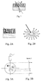
- the transmitted part is deflected with an angle that depends on the speed of propagation of the two media concerned. This is the phenomenon of refraction (see figure 1 attached).
- the proportion of reflected ultrasound, or reflection coefficient is directly related to the difference in acoustic impedance between the two media. This size is characteristic of the nature of the environment.
- the combination of the reflection and the refraction of the wave can induce multiple rebounds between the probe and the interface creating behind the interface ghost echoes called "echoes of repetition", the echoes being trapped between two reflecting interfaces before returning to the ultrasound probe.
- Attenuation is the loss of intensity of the ultrasound signal as a function of the depth of penetration of the tissues and their compositions.
- the system will automatically compensate for this decrease by amplifying the received signal so as to cancel the attenuation that the ultrasonic wave would have suffered if it had only passed through soft tissues.
- the tissues crossed by the ultrasound beam do not have soft tissue attenuation characteristics, there is either a reinforcement (this is the case for a liquid, which will have less attenuating power than that of soft tissues), or the appearance of shadows (this is the case for bone or gas, which will have an attenuating power greater than that of soft tissues).
- heterogeneous media are represented by scattering echoes.
- the echogenicity (the faculty of generating echoes) of the parenchymal organs, for example, is essentially formed by scattering echoes, the intensity of which depends on the tissue homogeneity (see Figures 2A and 2B appended).
- the invention essentially consists in reproducing by simulation an ultrasound image reproducing all the effects of attenuation, reflection, refraction and dispersion.
- the invention consists in reproducing two-dimensional images (representing one or more ultrasound planes) by simulating several ultrasonic beams emitted from a virtual probe that can be controlled in position and orientation and positioned in the volume of the MRI medical image.
- the important reflection phenomena of the wave will be observed at the interfaces between the liquids or the soft tissues on the one hand and the air or the bones on the other hand.
- the most important normal incidence reflection coefficients are observed between structures whose gray levels can be sufficiently far away in an MRI image according to the chosen acquisition sequence. Any MRI image can not therefore meet this criterion, and only the MRI images to differentiate the different structures that we seek to observe will then be transformed into ultrasound images.
- the large variations in the gray level between these different structures can be easily calculated in real time along the ray launched in such an MRI image.
- This gradient can then be translated into a reflection whose order of magnitude can either be parameterized interactively or be calculated automatically.
- the main advantage of this method implemented by the invention thus lies in the fact that it is not necessary to perform an initial segmentation of the organs to create an ultrasound image from an MRI image without pre-processing and in real time. which represents one of the main advantages of the invention.
- the subject of the invention is a process for the simulation or digital synthesis of ultrasound images, characterized by the direct, real-time, or near-real-time, transformation of the information contained in a medical or veterinary image of the MRI type, without delimitation. or segmentation of the organs or structures contained in the data volume of the MRI image, according to one or more two-dimensional observation windows that can be modified in real time, or near real time, in dimension, in position, in direction and in orientation, of which the characteristics are a function of the type of a determined virtual ultrasound probe, and reproducing all the effects of attenuation, reflection, refraction and dispersion and the adjustment effects of a real ultrasound image, each ultrasound image supplied cumulative the results of simulations of the aforementioned effects.
- the method advantageously performs the simulation of two-dimensional ultrasound images whose observation window is obtained by the simulation of several ultrasonic beams, oriented in parallel between them in the manner of a linear probe or oriented in different divergent directions in the manner of a sector probe, corresponding to a set of line segments originating from a virtual source characterizing the shape, direction, orientation and the dimension of the virtual probe and whose modifiable length makes it possible to simulate the frequency of the ultrasound by determining the maximum depth of exploration.
- a plane section with acquisition of the data contained in the portion of plane defined by the above-mentioned line segments, or by averaging data located on either side of said plan portion (in the absence of data on said plan portion), so as to obtain a two-dimensional data matrix extracted from said 3D MRI image.
- the method performs the simulation of three-dimensional ultrasound images defined by several two-dimensional observation windows simulated and oriented with differential offsets with respect to the position and the orientation of the virtual probe, or about its axis, each window then being characterized by a different angle around the median axis of this probe, or at the end of this probe, each window then being characterized by a different angle around the axis perpendicular to the observation plane of this probe.
- the method preferably consists in creating one or more window (s) or analysis space (s) for simulating two-dimensional or three-dimensional ultrasound images, window (s) or space (s) defined by the plane or volume in which a virtual sound wave simulated by a set of line segments originating at the virtual ultrasound probe, and ultimately representing a rectangle, a partial disk, a tube or a sphere portion centered on the origin of the probe, this volume varying according to the degree of precision of the final simulation of the ultrasound image.
- the method advantageously comprises the simulation of the ultrasound dispersion effects by the traversed structures present in a real ultrasound image, this simulation resulting in the creation of an absorption image limited to the observation window defined above, obtained by transforming the intensity levels n contained in the MRI image limited to the window or analysis space also defined previously, in grayscale I (n) of an ultrasound image, by the definition and application of a transfer function I simulating the orders of magnitude of the acoustic impedance values of the traversed structures, said function I being able to be continuous or not, linear or not depending on the modality, the type and the characteristics of the initial MRI image.
- the method advantageously comprises the simulation of the effects of reflection, refraction and attenuation of ultrasound by the traversed interfaces present in a real ultrasound image, this simulation resulting in the creation, on the one hand, of an image of attenuation simulating the effects of ultrasound shadows and the effects of sonographic reinforcements visible respectively beyond an interface between a soft tissue or a fluid and air or bone, and beyond an interface between a fluid and a soft tissue, and, on the other hand, a multiple echo image or mask, simulating the reverberation effects of an ultrasound echo inside a visible bone beyond an interface between a soft tissue or a liquid and bone, these images being both limited to the observation window defined above, and obtained along the paths of the directed ray throws (defining the window or windows ( s) or analysis area (s) by the real-time detection of the interfaces calculated by thresholding, gradient and / or filtering techniques of the initial MRI image densities limited to the window or analysis space defined according to claim 4.
- the method advantageously comprises the simulation of the dispersion noises experienced by the ultrasound in the tissues traversed or their effects.
- This simulation results in the creation of an image limited to the observation window defined above, simulating the effects of refraction and dispersion in an ultrasound image, obtained by calculating the effects of refraction and dispersion of the tissues traversed by the simulated ultrasound wave described above, this simulation being carried out either by defining a general noise in the image, or by more specifically simulating the aforementioned effects by detecting and characterizing the interfaces between the different structures of the scanned analysis window.
- the method advantageously comprises the simulation of the effects of the setting of the virtual or simulated ultrasound probe, resulting in the creation of an image or mask of limited adjustment (e) to the - 11 - observation window defined above and simulating the brightness, contrast, gain or any other adjustable parameter settings of the virtual or simulated ultrasound probe as previously defined.
- the method according to the invention realizes the creation of an ultrasound image limited to the observation window defined above, and combining the results of the four different simulations described above.
- the principle underlying the present invention is, for making ultrasound images of synthesis, to use directly three-dimensional MRI images, preferably of high precision, without performing a heavy pretreatment phase and significant consumer of time and processing power.
- ultrasound propagation can be modeled as a one-dimensional phenomenon.
- a first step of the method consists in performing a volumetric ray tracing directly in the three-dimensional MRI image in order to collect all the voxels lying in the investigation plane of the simulated virtual probe.
- Each possible propagation direction for the ultrasonic wave corresponds to a line of the resulting two-dimensional image.
- This image is then analyzed in order to extract at least two different information.
- the acoustic behavior of each pixel is estimated and, on the other hand, the interfaces cut or traversed by the rays (directions of propagation) are detected, identified and marked (soft tissue, bone, gas, liquid,. ..).
- At least three different simulations are performed, namely, a simulation of the ultrasound reflection effects by the traversed interfaces (reverberation), a simulation of the absorption effects of ultrasound by the traversed structures (attenuation) and a simulation of the dispersion effects and a noise matrix, associated with a simulation of the virtual probe settings.
- the first simulation provides a so-called “multiple echoes” image, created by exploiting the knowledge of the nature and position of the interfaces between organs or regions of different tissues. Thanks to this image, multiple echoes are detected and represented.
- the second simulation provides an absorption image that represents the accumulation of the absorption characteristics of materials and substances along the ultrasonic wave.
- the third simulation provides the background image or background texture, which is generated by combining, for each pixel, the value read in the MRI image and the information relating to the nature of the tissues concerned and its acoustic characteristics.
- the background image is further blurred by using randomly generated noise.
- the final simulated ultrasound image is the result of the fusion or combination of the above three images at least, limited to an observation window determined by the nature and the setting of the simulated probe, said resultant image being furthermore applied in a texture before it is displayed.
- This realization is based on a T2-type obstetric MRI image.
- the goal is to simulate an antenatal ultrasound and the algorithms described here have been optimized to improve the rendering of structures specific to the fetus. For the simulation of another type of examination or the same examination based on another type of MRI image, these algorithms may therefore be substantially different.
- the first module 1 of the algorithm consists in simulating the ultrasound probe, that is to say to define its static properties (2D or 3D probe, linear or sector probe) and its variable properties (position, direction, orientation, frequency of the emitted wave, gain, contrast, etc .).
- the implementation of this first module 1 is necessary for the realization of the invention which consists in creating a virtual ultrasound image from a virtual or simulated probe.
- the second module 2 (comprising four sub-modules 3, 3 ', 3 ", 3"'), which more particularly characterizes the invention, consists in creating the ultrasound image that would be generated by an actual ultrasound probe, the parameters of which are provided. by the first module 1, if it was frequency-tuned, localized, directed, oriented and parameterized according to the information provided by the first module, on a real subject of which part of the anatomical characteristics are provided by the MRI image.
- the ultrasound simulation module 2 is composed, as shown in FIG. figure 6 annexed, four main sub-modules 3, 3 ', 3 ", 3"' respectively performing dispersion, reflection, refraction and absorption (attenuation), noises due to refraction and dispersion and effects due to the setting of the probe, such as gain or contrast, for example.
- the first step of the simulation is to define the restricted space in which the simulated image will be recreated, as well as the analysis space to recreate the effects of absorption, reflection and noise. of refraction and dispersion in this image.
- the space of the image will correspond to a plane limited in its dimensions by the size of the probe and the frequency of the transmitted signal. If it is a linear probe, the shape of this space will be a rectangle whose width will be equal to the width of the probe and the length will depend on the frequency, whereas in the case of a sector probe, the shape of this space will be a disk section whose radius will depend on the frequency.
- the image space will in fact consist of several 2D spaces of sectoral or linear type.
- the analysis space corresponds for its part to the simulation of the propagation space and return to the probe of ultrasonic waves. he may vary depending on a compromise between realism and speed that can be defined by the user.
- On a weak computer for example, it will be possible to maintain an analysis space equal to the space of the image, but in this case, the tissues located outside the space of the ultrasound image will not be able to influence the image, as can be the case in the case of refraction in particular. If the computer is more powerful, widening the analysis space will improve the simulation while maintaining a real-time image generation. In absolute terms, it is unnecessary to keep the information beyond the maximum distance defined by the frequency of the waves emitted by the probe.
- the shape of the space thus generated will again depend on the type of probe used and will lead to either a sphere portion (linear or sectoral 2D or 3D probe), or to a complete cylinder (endoluminal ultrasound probe).
- the first submodule 3 consists in simulating the phenomenon of dispersion of the tissues traversed by the ultrasonic waves.
- the principle of the invention consists, in this regard, in simulating this phenomenon by transforming each level of gray or intensity of the MRI image into a gray level in the ultrasound image.
- a transfer function that converts a gray level or intensity n in the MRI image in an ultrasound intensity I (n) in the ultrasound image.
- This function may vary according to the characteristics of the MRI acquisition, depending on the nature of the organs on which the simulation will focus and / or according to the desired level of realism. It could for example be algebraic or correspond to a simple table of values.
- I echography (d) coef * d.
- any function will cause errors on certain values, since any transfer function can only attempt to simulate the real effect of the dispersion without ever being able to equal it since, physically, the gray levels or intensity of a MRI image and absorption of ultrasonic waves remain two physically uncorrelated phenomena. Whatever the level of precision of the transfer function, the approximations it entails may in any case be reduced by the other effects of reflection, refraction or absorption.
- the final result of this first sub-module 3 is the definition of a first image, corresponding to an echographic viewing window in gray levels without effect.
- the second sub-module 3 aims to simulate the phenomena of reflection, refraction and attenuation of the interfaces defining the effects related to these reflections, that is to say shadows and multiple echoes.
- the principle of the invention consists, in this regard, in simulating these oriented and directed phenomena as a function of the parameters of the probe, that is to say, limited to the viewing window, then in calculating the reflections according to the variations grayscale or intensity of the MRI image.
- the definition of these interfaces can be done in several ways: either by calculating the gradient of the initial MRI image, or by calculating the gradient of the modified MRI image by a transfer function equal to or different from the transfer function. defined in the first sub-module, or by any other method that leads to a similar result.
- the shadow phenomenon will appear when the interface will be too large, that is to say when the difference in impartance of two neighboring tissues will be too great.
- Air and bone have very dark gray levels in an MRI image since they contain very little water and therefore very few protons, while soft tissues and water may have median and high values grayscale or intensity in an MRI image according to the chosen modality.
- the principle of the invention will therefore be to create along the radius a strong attenuation of the densities beyond a detected interface if the interface is composed of very low values in this type of MRI image (corresponding to the air or bone).
- the simulation of this shadow will lead to a image, called attenuation mask, limited to the viewing window and whose actual values will be between 0 and 1 in order to be able to multiply them by the value of the absorption window.
- the attenuation of the gray levels of the final image will therefore be obtained by multiplying the initial values by the attenuation value.
- Some small interfaces may also cause a shadow phenomenon when they are not perpendicular to the direction of the ray.
- This phenomenon named edge shadow, is very important in obstetric ultrasound and is especially visible in the skull of the fetus.
- the direction of the gradient of the image must be taken into account to determine the orientation of the interface. The more oblique this is, the more important the phenomenon will be.
- the attenuation mask is modified according to this result.
- Some interfaces may have different attenuation effects that are characterized by enhancement.
- Reinforcement is a phenomenon of increasing gray levels in the direction of ultrasound waves emitted through a liquid. It can easily result in a slight increase in density beyond a detected interface if the interface is composed of very high gray levels in an MRI image (value corresponding to liquids). To characterize this increase, the simulation of this reinforcement will consist in defining in the reflection mask values higher than 1. In ultrasound images, a reinforcement will also cause a shadow effect on both sides of the liquid region. To characterize these shadows, the simulation will consist in defining in the reflection mask values close to 0.
- Important interfaces may finally create an effect called multiple echo which corresponds to a replication of an interface in depth in the same axis of the rays having defined the interface between a soft tissue or water and a bone or a solid element.
- the principle of the invention will therefore consist in creating along the axis of each ray a replication of the interface beyond a detected interface if this interface is composed of gray levels or intensity close to 0 in the MRI image (corresponding to the bone).
- the simulation of this multiple echo will result in an image, called a multiple echo window, limited to the viewing window and whose values will display the replications of the interface by increasing the gray levels of the ultrasound image. It may therefore be a mask whose pixel value will be multiplied by the value of the gray levels of the absorption window, or else an image whose value of the gray levels will be added to the value of the pixels. gray levels of the absorption window.
- the purpose of the third submodule 3 is to simulate the phenomena of dispersion noise, the principle of the invention being, in this respect, to simulate these phenomena by defining an image that will make it possible to modify the value of the gray levels of the absorption window
- the simulation of these phenomena is undoubtedly the most complex since they are not taken into account by the reconstruction software of a real ultrasound image and are thus characterized as a noise. implemented by a compromise between the realism of the effect and the processing time to achieve it.
- the simplest method is to calculate a random noise that reproduces a texture comparable to the noise observed in the ultrasound images.
- Gaussian noise oriented in the normal rays launched from the virtual probe and provides real-time first approximation simple and fast such noise.
- the most complex method is to calculate the two effects independently, taking into account their characteristics.
- the result of the third sub-module 3 "will ultimately be an image or a mask for changing the intensities of the absorption image.
- the purpose of the fourth submodule 3 is to simulate the parameters for adjusting the image supplied by the ultrasound probe.
- the principle of the invention consists, in this respect, in simulating these adjustments, which generally correspond to contrast, brightness or even gain functions more or less complex, by a mask for changing the simulated ultrasound image.
- image adjustment mask an image, limited to the window of visualization and whose real values will be between 0 and n, in order to be able to multiply them by the value of the simulated ultrasound image.
- the principle of the invention consists in providing a simulated ultrasound image with each of the effects and settings of an actual ultrasound image.
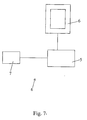
- a system 4 for simulation or digital synthesis of ultrasound images or real-time or quasi-real-time ultrasound simulator comprising at least one computer memory processing unit 5, a screen 6 of image display (s) and at least one means 7 for controlling and programming for a user.
- This simulator is characterized in that it implements the method for simulating or synthesizing digital images described above and in that said at least one control and programming means 7 is at least able to indicate to the user.
- treatment unit 5 the type of virtual ultrasound probe to be simulated, as well as, in real time or near real time, the various adjustment parameters and manipulation of this probe by the user, and possibly the medical or veterinary image of 3D MRI type selected by the user from several available images.
- said at least one control and programming means 7 comprises a force or force feedback interface making it possible to simulate the positioning characteristics of the probe relative to the virtual subject.
- a force or force feedback interface making it possible to simulate the positioning characteristics of the probe relative to the virtual subject.
- the method according to the invention can be applied as much for the simulation of two-dimensional ultrasound images, as three-dimensional (reconstructed from two-dimensional images).
Abstract
Description
La présente invention concerne le domaine des techniques d'imagerie et d'exploration, notamment dans le domaine médical et plus particulièrement dans le contexte de la simulation ou de la synthèse d'images virtuelles, et a pour objet un procédé et un système de simulation ou de synthèse numérique d'images échographiques, planes ou non.The present invention relates to the field of imaging and exploration techniques, particularly in the medical field and more particularly in the context of the simulation or synthesis of virtual images, and relates to a method and a simulation system or digital synthesis of ultrasound images, planar or not.
Afin de former ses étudiants, la médecine moderne commence à se doter de simulateurs médicaux de plus en plus perfectionnés.In order to train its students, modern medicine is beginning to acquire more and more sophisticated medical simulators.
Les simulateurs ont fait leurs preuves dans les domaines militaires et aéronautiques et offrent un nombre assez important d'avantages :
- le simulateur ne monopolise pas de matériel utile à l'activité réelle,
- la diversité des simulations est très importante, depuis la situation courante jusqu'aux cas rares,
- des aides impensables en formation traditionnelle peuvent être mises en place : regarder toutes ou partie de ses actions d'un point de vue identique ou différent, ou pouvoir recommencer la partie non satisfaisante de la simulation autant de fois que nécessaire,
- la simulation permet une évaluation fiable et objective des aptitudes acquises. Et surtout, elle permet de simuler des situations dans lesquelles les risques sont très élevés pour des débutants et/ou le patient.
- the simulator does not monopolize any material useful to the real activity,
- the diversity of the simulations is very important, from the current situation to the rare cases,
- unthinkable aids in traditional training can be put in place: to look at all or part of his actions from the same or different point of view, or to be able to repeat the unsatisfactory part of the simulation as many times as necessary,
- the simulation allows a reliable and objective evaluation of acquired skills. And above all, it allows to simulate situations in which the risks are very high for beginners and / or the patient.
Ainsi, et pour permettre notamment lors de séances d'entraînement à des chirurgiens de contrôler le positionnement et le déplacement d'instruments dans le corps d'un patient, un besoin existe pour un procédé et un outil susceptible de synthétiser des images échographiques en temps réel ou quasi temps réel.Thus, and in particular to allow during training sessions for surgeons to control the positioning and movement of instruments in the body of a patient, a need exists for a method and a tool capable of synthesizing ultrasound images in time. real or near real time.
Par exemple, un article rédigé par
L'échographie, dont la technique et les caractéristiques sont bien connues de l'homme du métier, présente beaucoup d'avantages par rapport aux autres techniques d'imagerie : elle n'est pas nocive à haute dose comme la radiographie et le scanner, le coût des appareils et celui des examens est moins élevé, et l'encombrement des échographes est faible. De plus, dans la grande majorité des cas, avant de prescrire un examen plus poussé comme une Imagerie par résonance magnétique, une échographie de la zone impliquée dans la pathologie du patient est effectuée. Enfin, l'acquisition rapide des images lui confère un caractère dynamique très intéressant pour l'observation ou le guidage. Le principe de l'invention repose sur la transformation directe d'images par résonance magnétique nucléaire RMN (ou RMN), ci-après également dénommées Imagerie par résonance Magnétique (ou IRM), en images échographiques. Afin de comprendre l'invention, il est donc nécessaire de décrire succinctement les principes de ces différentes images.Ultrasound, whose technique and characteristics are well known to those skilled in the art, has many advantages over other imaging techniques: it is not harmful in high doses such as radiography and CT, the cost of the apparatus and that of the examinations is lower, and the size of the ultrasound scanners is small. In addition, in the vast majority of cases, before prescribing a further examination such as Magnetic Resonance Imaging, an ultrasound the area involved in the pathology of the patient is performed. Finally, the rapid acquisition of images gives it a very interesting dynamic character for observation or guidance. The principle of the invention is based on the direct transformation of NMR (or NMR) nuclear magnetic resonance images, hereinafter also called Magnetic Resonance Imaging (or MRI), in ultrasound images. In order to understand the invention, it is therefore necessary to briefly describe the principles of these different images.
L'Imagerie par Résonance Magnétique (IRM) est une technique de diagnostic qui fournit des images en coupe de grande précision anatomique sans utilisation de rayons X ni d'autres radiations. L'IRM est basée sur le phénomène physique de résonance magnétique nucléaire (RMN). Elle utilise les propriétés de la matière et ne concerne que les noyaux d'hydrogène, très abondants dans le corps humain. Un aimant cylindrique creux fournit un champ magnétique intense (typiquement de 1 à 3 Tesla) environ 60 000 fois supérieur au champ magnétique terrestre. Ce champ magnétique fait apparaître au sein des différents tissus de l'organisme une aimantation qui est due aux noyaux d'hydrogène, comme si chaque noyau se comportait comme une petite boussole. Le phénomène de résonance magnétique permet de mesurer cette aimantation. Pour cela, on perturbe les noyaux d'hydrogène en émettant vers le patient une onde électromagnétique. Sous l'effet de cette impulsion, les noyaux d'hydrogène font basculer leur aimantation par rapport à la direction du champ magnétique. A la fin de l'impulsion, l'aimantation revient à sa position d'équilibre : c'est le retour de l'aimantation à cet état d'équilibre qui est mesuré. Les images obtenues seront très différentes selon les réglages de l'appareil choisi et le type d'information recherché. Les principales images dépendront ainsi de la pondération qui pourra être de type T1 (calcul de la relaxation selon l'axe longitudinale de l'aimantation), ou T2 (calcul de la relaxation selon l'axe transversale de l'aimantation), en densité de protons, en mode FLAIR (FLuid Attenuation Inversion Reconvery), en T2*, chacune des ces images pouvant être réalisée en mode écho de Spin ou écho de gradient. Quelque soient les réglages, c'est bien la présence des noyaux d'hydrogène et donc d'eau dans l'image qui caractérisera ces images. Les niveaux de gris varieront ainsi en fonction de cette densité, mais seront très variables d'une image à une autre. Le temps de relaxation des structures traversées étant déterminant pour le niveau de gris finale dans l'image IRM, il est important de noter que ce temps de relaxation sera d'autant plus faible que les structures visualisées seront dense et présenteront peu d'eau. A l'inverse, l'eau aura un temps de relaxation très élevée.Magnetic Resonance Imaging (MRI) is a diagnostic technique that provides anatomically accurate sectional images without the use of X-rays or other radiation. MRI is based on the physical phenomenon of nuclear magnetic resonance (NMR). It uses the properties of matter and only concerns the hydrogen nuclei, very abundant in the human body. A hollow cylindrical magnet provides an intense magnetic field (typically 1 to 3 Tesla) about 60,000 times greater than the Earth's magnetic field. This magnetic field gives rise to magnetization in the various tissues of the body, which is due to the hydrogen nuclei, as if each nucleus behaved like a small compass. The magnetic resonance phenomenon makes it possible to measure this magnetization. For this, the hydrogen nuclei are disturbed by emitting an electromagnetic wave towards the patient. Under the effect of this impulse, the hydrogen nuclei tilt their magnetization with respect to the direction of the magnetic field. At the end of the impulse, the magnetization returns to its position of equilibrium: it is the return of the magnetization to this state of equilibrium which is measured. The images obtained will be very different depending on the settings of the chosen device and the type of information sought. The main images will thus depend on the weighting that can be of type T1 (calculation of the relaxation along the longitudinal axis of the magnetization), or T2 (calculation of the relaxation along the transversal axis of the magnetization), in density of protons, in FLAIR mode (FLuid Attenuation Inversion Reconvery), in T2 *, each of these images being able to be realized in echo mode of Spin or echo of gradient. Whatever the settings, it is the presence of hydrogen nuclei and therefore water in the image that will characterize these images. The gray levels will vary as a function of this density, but will vary greatly from one image to another. The relaxation time of the traversed structures being determinant for the final gray level in the MRI image, it is important to note that this relaxation time will be even lower than the visualized structures will be dense and will have little water. Conversely, the water will have a very high relaxation time.
Le tableau ci-après indique, à titre d'exemples, pour différents milieux, l'intensité correspondante dans une image IRM obstétrique de type T2. Il est bien entendu que ces valeurs sont très dépendantes du réglage des appareils et des conditions et du mode d'acquisition.
L'échographie est, quant à elle, une technique d'imagerie médicale qui utilise les ultrasons pour obtenir une image de l'intérieur du corps. La sonde de l'échographe envoie des ultrasons qui reviennent à la sonde, après s'être réfléchis sur l'organe que l'on veut étudier, afin d'être traités par un ordinateur. L'image échographique est donc une image par réflexion. La réflexion du faisceau ultrasonore se fait sur des interfaces constituées par des tissus ayant des impédances acoustiques différentes et aussi dans une moindre mesure sur les irrégularités de ces tissus du fait de la dispersion. Les impulsions ultrasonores obéissent aux mêmes lois de propagation, réflexion et réfraction que celles de l'optique. Enfin, le faisceau ultrasonore est atténué en fonction de la nature des organes qu'il traverse.Ultrasound is a medical imaging technique that uses ultrasound to get an image of the inside of the body. The ultrasound probe sends ultrasound that returns to the probe, after having reflected on the organ that one wants to study, in order to be treated by a computer. The ultrasound image is therefore a reflection image. The reflection of the ultrasonic beam is done on interfaces constituted by tissues having different acoustic impedances and also to a lesser extent on the irregularities of these tissues due to the dispersion. Ultrasonic pulses obey the same laws of propagation, reflection and refraction as those of optics. Finally, the ultrasound beam is attenuated according to the nature of the organs through which it passes.
Les paramètres déterminants dans la propagation des sons dans les différents milieux sont la densité ou masse volumique (d) et la vitesse de propagation des sons (v).The determining parameters in the propagation of sounds in different media are the density or density (d) and the speed of sound propagation (v).
L'impédance acoustique (Z) est définie par le produit de ces deux caractéristiques du milieu: Z = d x v. Le tableau ci-après indique les impédances acoustiques pour différents milieux présents dans tout corps humain ou animal.
Les quatre phénomènes physiques qui entrent en jeu dans le comportement d'une onde ultrasonore sont : la réflexion, la réfraction, l'atténuation et la dispersion.The four physical phenomena that come into play in the behavior of an ultrasonic wave are: reflection, refraction, attenuation, and dispersion.
Un écho est un son (onde sonore) qui est réfléchi et qui est réceptionné après un temps de latence, correspondant à son temps de déplacement dans le milieu concerné. Lorsque le faisceau ultrasonore arrive sur une surface réflective avec un angle oblique, une partie du faisceau est réfléchi avec un angle de réflexion égal à l'angle incident. Il s'agit du phénomène de réflexion. La partie transmise est déviée avec un angle qui dépend de la vitesse de propagation des deux milieux concernés. Il s'agit du phénomène de réfraction (voir
Ces valeurs montrent que dans l'organisme, les grandes différences d'impédance acoustique se rencontrent entre les tissus mous et l'air et entre les tissus mous et les tissus durs (os, calculs, corps étrangers). De telles interfaces sont très réfléchissantes ou très "échogènes" (génératrices d'échos). Derrière ces interfaces, une zone d'ombre apparaît puisque le signal sonore a été en grande partie réfléchi.These values show that in the body, large differences in acoustic impedance occur between soft tissues and air and between soft tissues and hard tissues (bone, stones, foreign bodies). Such interfaces are very reflective or very "echogenic" (echo generators). Behind these interfaces, a shadow zone appears since the sound signal has been largely reflected.
En échographie, l'interaction du faisceau ultrasonore avec une surface oblique lisse entraîne une disparition du signal, car aucun signal sonore ne revient directement sur la sonde après la réflexion oblique et le faisceau change de direction après la réfraction. Ce phénomène est à l'origine d'un artefact fréquent appelé "ombre de bord". L'influence de l'angle des ultrasons sur l'aspect échographique des structures organiques observées est plus ou moins marquée. Les tendons et les ligaments font partie des structures dites anisotropiques pour lesquelles l'aspect échographique est fortement influencé par la direction du faisceau d'ultrasons.In ultrasound, the interaction of the ultrasound beam with a smooth oblique surface leads to a disappearance of the signal, because no sound signal returns directly to the probe after the oblique reflection and the beam changes direction after the refraction. This phenomenon is at the origin of a frequent artefact called "edge shadow". The influence of the ultrasound angle on the echographic aspect of the organic structures observed is more or less marked. Tendons and ligaments are part of so-called anisotropic structures for which the ultrasound appearance is strongly influenced by the direction of the ultrasound beam.
De plus, la combinaison de la réflexion et de la réfraction de l'onde pourra induire des rebonds multiples entre la sonde et l'interface créant en arrière de l'interface des échos fantômes appelés "échos de répétition", les échos se retrouvant piégés entre deux interfaces réfléchissantes avant de revenir vers la sonde échographique.Moreover, the combination of the reflection and the refraction of the wave can induce multiple rebounds between the probe and the interface creating behind the interface ghost echoes called "echoes of repetition", the echoes being trapped between two reflecting interfaces before returning to the ultrasound probe.
L'atténuation est la perte d'intensité du signal échographique en fonction de la profondeur de pénétration des tissus et de leurs compositions. L'échographe va automatiquement compenser cette diminution en amplifiant le signal reçu de manière à annuler l'atténuation qu'aurait subi l'onde ultrasonore si elle n'avait traversé que des tissus mous. Dans le cas où les tissus traversés par le faisceau ultrasonographique n'ont pas les caractéristiques d'atténuation des tissus mous, il y a soit un renforcement (c'est le cas pour un liquide, qui va posséder un pouvoir atténuateur moindre que celui des tissus mous), soit l'apparition de cônes d'ombres (c'est le cas pour de l'os ou du gaz, qui vont posséder un pouvoir atténuateur supérieur à celui des tissus mous).Attenuation is the loss of intensity of the ultrasound signal as a function of the depth of penetration of the tissues and their compositions. The system will automatically compensate for this decrease by amplifying the received signal so as to cancel the attenuation that the ultrasonic wave would have suffered if it had only passed through soft tissues. In the case where the tissues crossed by the ultrasound beam do not have soft tissue attenuation characteristics, there is either a reinforcement (this is the case for a liquid, which will have less attenuating power than that of soft tissues), or the appearance of shadows (this is the case for bone or gas, which will have an attenuating power greater than that of soft tissues).
Néanmoins, l'atténuation du signal ne peut être compensée que jusqu'à une certaine limite à partir de laquelle le signal n'est plus suffisamment significatif par rapport au bruit. Le tableau ci-après indique, pour différentes fréquences, la profondeur d'exploration maximale des ultrasons.
Dans les images échographiques, les milieux hétérogènes sont représentés par des échos de dispersion. L'échogénicité (la faculté à générer des échos) des organes parenchymateux, par exemple, est essentiellement formée par des échos de dispersion, dont l'intensité dépend de l'homogénéité tissulaire (voir
En conclusion, il s'avère que le traitement du signal effectué par l'ordinateur d'un échographe, afin de construire les images ultrasonores réelles repose sur un certain nombre d'hypothèses :
- 1) la direction du faisceau ultrasonore est unique
- 2) il n'y a pas de réflexions multiples
- 3) l'absorption du milieu est équivalente à celle des tissus mous
- 4) la vitesse de propagation d'une onde vaut 1540 m/s.
- 1) the direction of the ultrasound beam is unique
- 2) There are no multiple reflections
- 3) the absorption of the medium is equivalent to that of the soft tissues
- 4) the propagation speed of a wave is 1540 m / s.
Lorsqu'une ou plusieurs de ces hypothèses sont fausses, des échos parasites, qui ne correspondent pas à une structure réelle, apparaissent sur l'image : ce sont des artefacts. L'information de base d'une image échographique repose de ce fait sur les propriétés de réflexion, de réfraction, d'atténuation et de dispersion des tissus. En tenant compte de ces différents effets, l'image ultrasonore est reconstituée à partir des informations recueillies par la sonde et transmises à l'appareil. Les informations sont traitées par un logiciel complexe qui permet de déterminer la position et l'intensité de l'écho et de représenter l'image (ou le signal) pour une interprétation par l'opérateur.When one or more of these assumptions are false, clutter echoes, which do not correspond to a real structure, appear on the image: they are artifacts. The basic information of an ultrasound image is therefore based on the properties of reflection, refraction, attenuation and dispersion of tissues. Taking into account these different effects, the ultrasound image is reconstituted from the information collected by the probe and transmitted to the device. The information is processed by complex software that determines the position and intensity of the echo and represents the image (or signal) for interpretation by the operator.
L'image échographique peut enfin être représentée selon plusieurs modes :
- Le premier mode est le mode de représentation de l'image le plus primitif. Il consiste à afficher l'amplitude du signal recueilli par la sonde en fonction de la profondeur (
figure 3B ). Un seul faisceau ultrasonore de direction constante est utilisé (figure 3A ). Ce mode était autrefois utilisé en neurologie pédiatrique et en ophtalmologie. - Le second mode par brillance, est le mode de représentation le plus commun. Il s'agit de représenter l'intensité du signal non plus par une courbe mais par la brillance d'un point sur écran. Plus le point est brillant, plus la réflexion des ultrasons a été importante et donc, plus l'écho est intense (voir
figures 4A et 4B annexées).
- The first mode is the mode of representation of the most primitive image. It consists of displaying the amplitude of the signal collected by the probe as a function of the depth (
figure 3B ). Only one ultrasonic beam of constant direction is used (figure 3A ). This mode was formerly used in pediatric neurology and ophthalmology. - The second mode by brilliance, is the most common mode of representation. It is a question of representing the intensity of the signal not more by a curve but by the brilliance of a point on screen. The brighter the point, the more important the ultrasound reflection has been and therefore the more intense the echo (see
Figures 4A and 4B appended).
Lorsque plusieurs faisceaux ultrasonores parallèles les uns aux autres sont utilisés (sonde linéaire) ou lorsque le même faisceau ultrasonore est orienté dans des directions différentes (sonde sectorielle) on obtient une image en 2 (deux) dimensions (bidimensionnelle) qui représente une coupe de la structure explorée (voir
En partant du constat fait par les inventeurs, d'une similitude entre la densité de protons d'un tissu visualisable par une image IRM avec l'impédance acoustique de ce même tissu visualisable dans une image échographique, l'invention consiste essentiellement à reproduire par simulation une image échographique reproduisant l'ensemble des effets d'atténuation, de réflexion, de réfraction et de dispersion.Starting from the finding made by the inventors, of a similarity between the proton density of a fabric that can be visualized by an MRI image with the acoustic impedance of the same tissue that can be visualized in an ultrasound image, the invention essentially consists in reproducing by simulation an ultrasound image reproducing all the effects of attenuation, reflection, refraction and dispersion.
Les principales caractéristiques du procédé selon l'invention ressortent de la revendication 1 annexée et des caractéristiques supplémentaires ressortent des revendications 2 à 9 annexées.The main features of the method according to the invention are apparent from the appended
L'invention consiste plus précisément à reproduire des images bidimensionnelles (représentant un ou plusieurs plans échographiques) en simulant plusieurs faisceaux ultrasonores émis depuis une sonde virtuelle contrôlable en position et en orientation et positionnés dans le volume de l'image médicale IRM.More precisely, the invention consists in reproducing two-dimensional images (representing one or more ultrasound planes) by simulating several ultrasonic beams emitted from a virtual probe that can be controlled in position and orientation and positioned in the volume of the MRI medical image.
Comme indiqué précédemment, les phénomènes de réflexion importants de l'onde seront observés au niveau d'interfaces entre les liquides ou les tissus mous d'une part et l'air ou les os d'autre part. En fait, les plus importants coefficients de réflexion en incidence normale sont observés entre des structures dont les niveaux de gris peuvent être suffisamment éloignés dans une image IRM selon la séquence d'acquisition choisie. Toute image IRM ne pourra donc pas répondre à ce critère, et seules les images IRM permettant de différencier les différentes structures que l'on cherche à observer seront alors transformables en images échographiques.As indicated above, the important reflection phenomena of the wave will be observed at the interfaces between the liquids or the soft tissues on the one hand and the air or the bones on the other hand. In fact, the most important normal incidence reflection coefficients are observed between structures whose gray levels can be sufficiently far away in an MRI image according to the chosen acquisition sequence. Any MRI image can not therefore meet this criterion, and only the MRI images to differentiate the different structures that we seek to observe will then be transformed into ultrasound images.
Les variations importantes du niveau de gris entre ces différentes structures peuvent être facilement calculées en temps réel le long du rayon lancé dans une telle image IRM. Ce gradient pourra alors être traduit en une réflexion dont l'ordre de grandeur pourra soit être paramétré de façon interactive, soit être calculé automatiquement.The large variations in the gray level between these different structures can be easily calculated in real time along the ray launched in such an MRI image. This gradient can then be translated into a reflection whose order of magnitude can either be parameterized interactively or be calculated automatically.
L'intérêt principal de cette méthode mise en oeuvre par l'invention repose ainsi sur la non-nécessité de réaliser une segmentation initiale des organes pour créer une image échographique à partir d'une image IRM sans pré-traitement et en temps réel, ce qui représente un des principaux avantages de l'invention.The main advantage of this method implemented by the invention thus lies in the fact that it is not necessary to perform an initial segmentation of the organs to create an ultrasound image from an MRI image without pre-processing and in real time. which represents one of the main advantages of the invention.
Ainsi, l'invention a pour objet un procédé de simulation ou de synthèse numérique d'images échographiques, caractérisé par la transformation directe en temps réel, ou quasi temps réel, des informations contenues dans une image médicale ou vétérinaire de type IRM, sans délimitation ou segmentation des organes ou structures contenus dans le volume de données de l'image IRM, selon une ou plusieurs fenêtres d'observation bidimensionnelles modifiables en temps réel, ou quasi temps réel, en dimension, en position, en direction et en orientation, dont les caractéristiques sont fonction du type d'une sonde échographique virtuelle déterminée, et reproduisant l'ensemble des effets d'atténuation, de réflexion, de réfraction et de dispersion et des effets de réglage d'une image échographique réelle, chaque image échographique fournie cumulant les résultats des simulations des effets précités.Thus, the subject of the invention is a process for the simulation or digital synthesis of ultrasound images, characterized by the direct, real-time, or near-real-time, transformation of the information contained in a medical or veterinary image of the MRI type, without delimitation. or segmentation of the organs or structures contained in the data volume of the MRI image, according to one or more two-dimensional observation windows that can be modified in real time, or near real time, in dimension, in position, in direction and in orientation, of which the characteristics are a function of the type of a determined virtual ultrasound probe, and reproducing all the effects of attenuation, reflection, refraction and dispersion and the adjustment effects of a real ultrasound image, each ultrasound image supplied cumulative the results of simulations of the aforementioned effects.
Selon une première caractéristique de l'invention, le procédé réalise avantageusement la simulation d'images échographiques bidimensionnelles dont la fenêtre d'observation est obtenue par la simulation de plusieurs faisceaux ultrasonores, orientés parallèlement entre eux à la manière d'une sonde linéaire ou orientés dans des directions différentes divergentes à la manière d'une sonde sectorielle, correspondant à un ensemble de segments de droite prenant leur origine à une source virtuelle caractérisant la forme, la direction, l'orientation et la dimension de la sonde virtuelle et dont la longueur modifiable permet de simuler la fréquence des ultrasons en déterminant la profondeur d'exploration maximale.According to a first characteristic of the invention, the method advantageously performs the simulation of two-dimensional ultrasound images whose observation window is obtained by the simulation of several ultrasonic beams, oriented in parallel between them in the manner of a linear probe or oriented in different divergent directions in the manner of a sector probe, corresponding to a set of line segments originating from a virtual source characterizing the shape, direction, orientation and the dimension of the virtual probe and whose modifiable length makes it possible to simulate the frequency of the ultrasound by determining the maximum depth of exploration.
On réalise ainsi dans le volume de données formant l'image IRM tridimensionnelle, une coupe plane avec acquisition des données contenues dans la portion de plan définie par les segments de droites précités, ou par moyennage des données situées de part et d'autre de ladite portion de plan (en cas d'absence de données sur ladite portion de plan), de manière à obtenir une matrice de données bidimensionnelle extraite de ladite image IRM 3D.Thus, in the data volume forming the three-dimensional MRI image, a plane section with acquisition of the data contained in the portion of plane defined by the above-mentioned line segments, or by averaging data located on either side of said plan portion (in the absence of data on said plan portion), so as to obtain a two-dimensional data matrix extracted from said 3D MRI image.
Selon une évolution possible de l'invention, il peut aussi être prévu que le procédé réalise la simulation d'images échographiques tridimensionnelles définies par plusieurs fenêtres bidimensionnelles d'observation simulées et orientées avec des décalages différentiels par rapport à la position et à l'orientation de la sonde virtuelle, soit autour de son axe, chaque fenêtre étant alors caractérisée par un angle différent autour de l'axe médian de cette sonde, soit à l'extrémité de cette sonde, chaque fenêtre étant alors caractérisée par un angle différent autour de l'axe perpendiculaire au plan d'observation de cette sonde.According to one possible development of the invention, it can also be provided that the method performs the simulation of three-dimensional ultrasound images defined by several two-dimensional observation windows simulated and oriented with differential offsets with respect to the position and the orientation of the virtual probe, or about its axis, each window then being characterized by a different angle around the median axis of this probe, or at the end of this probe, each window then being characterized by a different angle around the axis perpendicular to the observation plane of this probe.
Conformément à l'invention, le procédé consiste préférentiellement à créer un(e) ou plusieurs fenêtre(s) ou espace(s) d'analyse pour la simulation d'images échographiques bidimensionnelles ou tridimensionnelles, fenêtre(s) ou espace(s) défmi(e)(s) par le plan ou le volume dans lequel une onde sonore virtuelle simulée par un ensemble de segments de droite prenant leur origine au niveau de la sonde échographique virtuelle, et représentant au final un rectangle, un disque partiel, un tube ou une portion de sphère centré sur l'origine de la sonde, ce volume variant en fonction du degré de précision de la simulation finale de l'image échographique.According to the invention, the method preferably consists in creating one or more window (s) or analysis space (s) for simulating two-dimensional or three-dimensional ultrasound images, window (s) or space (s) defined by the plane or volume in which a virtual sound wave simulated by a set of line segments originating at the virtual ultrasound probe, and ultimately representing a rectangle, a partial disk, a tube or a sphere portion centered on the origin of the probe, this volume varying according to the degree of precision of the final simulation of the ultrasound image.
Le procédé comprend avantageusement la simulation des effets de dispersion des ultrasons par les structures traversées présentes dans une image échographique réelle, cette simulation aboutissant à la création d'une image d'absorption limitée à la fenêtre d'observation définie ci-dessus, obtenue par transformation des niveaux d'intensité n contenus dans l'image IRM limitée à la fenêtre ou à l'espace d'analyse également défini(e) précédemment, en niveaux de gris I(n) d'une image échographique, par la définition et l'application d'une fonction de transfert I simulant les ordres de grandeurs des valeurs d'impédance acoustique des structures traversées, ladite fonction I pouvant être continue ou non, linéaire ou non selon la modalité, le type et les caractéristiques de l'image IRM initiale.The method advantageously comprises the simulation of the ultrasound dispersion effects by the traversed structures present in a real ultrasound image, this simulation resulting in the creation of an absorption image limited to the observation window defined above, obtained by transforming the intensity levels n contained in the MRI image limited to the window or analysis space also defined previously, in grayscale I (n) of an ultrasound image, by the definition and application of a transfer function I simulating the orders of magnitude of the acoustic impedance values of the traversed structures, said function I being able to be continuous or not, linear or not depending on the modality, the type and the characteristics of the initial MRI image.
De plus, le procédé comprend avantageusement la simulation des effets de réflexion, de réfraction et d'atténuation des ultrasons par les interfaces traversées présentes dans une image échographique réelle, cette simulation aboutissant à la création, d'une part, d'une image d'atténuation simulant les effets d'ombres échographiques et les effets de renforcements échographiques visibles respectivement au delà d'une interface entre un tissu mou ou un liquide et de l'air ou de l'os, et au delà d'une interface entre un liquide et un tissu mou, et, d'autre part, d'un(e) image ou masque d'échos multiples, simulant les effets de réverbération d'un écho ultrasonore à l'intérieur d'un os visible au delà d'une interface entre un tissu mou ou un liquide et de l'os, ces images étant toutes deux limitées à la fenêtre d'observation définie ci-dessus, et obtenues le long des trajets des lancers de rayons orientés (définissant la ou les fenêtre(s) ou espace(s) d'analyse précité(e)(s)) par la détection en temps réel des interfaces calculées par des techniques de seuillages, de gradient et/ou de filtrage des densités de l'image IRM initiale limitée à la fenêtre ou à l'espace d'analyse défini(e) selon la revendication 4.In addition, the method advantageously comprises the simulation of the effects of reflection, refraction and attenuation of ultrasound by the traversed interfaces present in a real ultrasound image, this simulation resulting in the creation, on the one hand, of an image of attenuation simulating the effects of ultrasound shadows and the effects of sonographic reinforcements visible respectively beyond an interface between a soft tissue or a fluid and air or bone, and beyond an interface between a fluid and a soft tissue, and, on the other hand, a multiple echo image or mask, simulating the reverberation effects of an ultrasound echo inside a visible bone beyond an interface between a soft tissue or a liquid and bone, these images being both limited to the observation window defined above, and obtained along the paths of the directed ray throws (defining the window or windows ( s) or analysis area (s) by the real-time detection of the interfaces calculated by thresholding, gradient and / or filtering techniques of the initial MRI image densities limited to the window or analysis space defined according to
En outre, le procédé comprend avantageusement la simulation des bruits de dispersion subis par les ultrasons dans les tissus traversés ou de leurs effets. Cette simulation aboutit à la création d'une image limitée à la fenêtre d'observation définie ci-dessus, simulant les effets de réfraction et de dispersion dans une image échographique, obtenue par le calcul des effets de réfraction et de dispersion des tissus traversés par l'onde échographique simulée décrite précédemment, cette simulation étant réalisée soit en définissant un bruit général dans l'image, soit en simulant plus spécifiquement les effets précités en détectant et caractérisant les interfaces entre les différentes structures de la fenêtre d'analyse parcourue.In addition, the method advantageously comprises the simulation of the dispersion noises experienced by the ultrasound in the tissues traversed or their effects. This simulation results in the creation of an image limited to the observation window defined above, simulating the effects of refraction and dispersion in an ultrasound image, obtained by calculating the effects of refraction and dispersion of the tissues traversed by the simulated ultrasound wave described above, this simulation being carried out either by defining a general noise in the image, or by more specifically simulating the aforementioned effects by detecting and characterizing the interfaces between the different structures of the scanned analysis window.
Enfin, le procédé comprend avantageusement la simulation des effets du réglage de la sonde échographique virtuelle ou simulée, aboutissant à la création d'un(e) image ou masque de réglage limité(e) à la - 11 - fenêtre d'observation définie ci-dessus et simulant les réglages de la luminosité, du contraste, du gain ou de tout autre paramètre réglable de la sonde échographique virtuelle ou simulée tels que définis précédemment.Finally, the method advantageously comprises the simulation of the effects of the setting of the virtual or simulated ultrasound probe, resulting in the creation of an image or mask of limited adjustment (e) to the - 11 - observation window defined above and simulating the brightness, contrast, gain or any other adjustable parameter settings of the virtual or simulated ultrasound probe as previously defined.
De manière préférée, le procédé selon l'invention réalise la création d'une image échographique limitée à la fenêtre d'observation définie ci-dessus, et cumulant les résultats des quatre simulations différentes décrites précédemment.Preferably, the method according to the invention realizes the creation of an ultrasound image limited to the observation window defined above, and combining the results of the four different simulations described above.
Ainsi qu'il ressort de ce qui précède, le principe à la base de la présente invention consiste, pour réaliser des images échographiques de synthèse, à utiliser directement des images IRM tridimensionnelles, préférentiellement de grande précision, sans effectuer de phase de prétraitement lourde et consommatrice importante de temps et de puissance de traitement.As is apparent from the foregoing, the principle underlying the present invention is, for making ultrasound images of synthesis, to use directly three-dimensional MRI images, preferably of high precision, without performing a heavy pretreatment phase and significant consumer of time and processing power.
Pour optimiser le calcul de l'image échographique de synthèse, la propagation des ultrasons peut être modélisée en tant que phénomène unidimensionnel.To optimize the computation of the synthetic ultrasound image, ultrasound propagation can be modeled as a one-dimensional phenomenon.
A cet effet, une première étape du procédé consiste à réaliser un traçage de rayons volumétrique directement dans l'image IRM tridimensionnelle afin de recueillir tous les voxels se situant dans le plan d'investigation de la sonde virtuelle simulée. Chaque direction de propagation possible pour l'onde ultrasonore correspond à une ligne de l'image bidimensionnelle résultante.For this purpose, a first step of the method consists in performing a volumetric ray tracing directly in the three-dimensional MRI image in order to collect all the voxels lying in the investigation plane of the simulated virtual probe. Each possible propagation direction for the ultrasonic wave corresponds to a line of the resulting two-dimensional image.
Cette image est alors analysée en vue d'en extraire au moins deux informations différentes.This image is then analyzed in order to extract at least two different information.
D'une part, le comportement acoustique de chaque pixel est estimé et, d'autre part, les interfaces coupées ou traversées par les rayons (directions de propagation) sont détectées, identifiées et marquées (tissus mous, os, gaz, liquide, ...).On the one hand, the acoustic behavior of each pixel is estimated and, on the other hand, the interfaces cut or traversed by the rays (directions of propagation) are detected, identified and marked (soft tissue, bone, gas, liquid,. ..).
Ces opérations de traitement peuvent être réalisées à l'état non connecté, éventuellement directement dans l'image IRM.These processing operations can be performed in the unconnected state, possibly directly in the MRI image.
Sur la base de ces données, au moins trois simulations différentes sont réalisées, à savoir, une simulation des effets de réflexion des ultrasons par les interfaces traversées (réverbération), une simulation des effets d'absorption des ultrasons par les structures traversées (atténuation) et une simulation des effets de dispersion et d'une matrice de bruit, associées à une simulation des réglages de la sonde virtuelle.On the basis of these data, at least three different simulations are performed, namely, a simulation of the ultrasound reflection effects by the traversed interfaces (reverberation), a simulation of the absorption effects of ultrasound by the traversed structures (attenuation) and a simulation of the dispersion effects and a noise matrix, associated with a simulation of the virtual probe settings.
La première simulation fournit une image dite "échos multiples", créée en exploitant la connaissance de la nature et de la position des interfaces entre les organes ou les régions de tissus différents. Grâce à cette image, les échos multiples sont détectés et représentés.The first simulation provides a so-called "multiple echoes" image, created by exploiting the knowledge of the nature and position of the interfaces between organs or regions of different tissues. Thanks to this image, multiple echoes are detected and represented.
La seconde simulation fournit une image d'absorption qui représente l'accumulation des caractéristiques d'absorption des matières et substances le long de l'onde ultrasonore.The second simulation provides an absorption image that represents the accumulation of the absorption characteristics of materials and substances along the ultrasonic wave.
La troisième simulation fournit l'image de fond ou de texture de fond, qui est générée en combinant, pour chaque pixel, la valeur lue dans l'image IRM et l'information relative à la nature des tissus concernés et de ses caractéristiques acoustiques. L'image de fond est, en outre, rendue floue en utilisant un bruit généré aléatoirement.The third simulation provides the background image or background texture, which is generated by combining, for each pixel, the value read in the MRI image and the information relating to the nature of the tissues concerned and its acoustic characteristics. The background image is further blurred by using randomly generated noise.
L'image échographique simulée finale est le résultat de la fusion ou de la combinaison des trois images précitées au moins, limitée à une fenêtre d'observation déterminée par la nature et le réglage de la sonde simulée, ladite image résultante étant, en outre, appliquée dans une texture avant son affichage.The final simulated ultrasound image is the result of the fusion or combination of the above three images at least, limited to an observation window determined by the nature and the setting of the simulated probe, said resultant image being furthermore applied in a texture before it is displayed.
L'invention sera mieux comprise, grâce à la description ci-après, qui se rapporte à un mode de réalisation préféré, donné à titre d'exemple non limitatif, et expliqué avec référence aux dessins schématiques annexés, dans lesquels :
- la
figure 6 représente, sous la forme d'un algorithme, les principales étapes opératoires et de traitement réalisées par le procédé selon l'invention, et - la
figure 7 représente de manière schématique un simulateur mettant en oeuvre le procédé selon l'invention.
- the
figure 6 represents, in the form of an algorithm, the main operating and treatment steps carried out by the process according to the invention, and - the
figure 7 schematically represents a simulator implementing the method according to the invention.
Cette réalisation se base sur une image IRM obstétrique de type T2. Le but est de simuler une échographie prénatale et les algorithmes décrits ici ont donc été optimisés pour améliorer le rendu des structures propres au foetus. Pour la simulation d'un autre type d'examen ou du même examen basé sur un autre type d'image IRM, ces algorithmes pourront donc être sensiblement différents.This realization is based on a T2-type obstetric MRI image. The goal is to simulate an antenatal ultrasound and the algorithms described here have been optimized to improve the rendering of structures specific to the fetus. For the simulation of another type of examination or the same examination based on another type of MRI image, these algorithms may therefore be substantially different.
Compte tenu du principe de l'invention, il est nécessaire avant tout de lire l'image médicale ou vétérinaire de type IRM dont le volume de données fournira la base des informations permettant de recréer une échographie virtuelle du sujet observé.Given the principle of the invention, it is necessary first of all to read the medical or veterinary image type MRI whose data volume will provide the basis of information to recreate a virtual ultrasound of the subject observed.
A partir de ce volume de données, le premier module 1 de l'algorithme consiste à simuler la sonde échographique, c'est-à-dire à définir ses propriétés statiques (sonde 2D ou 3D, sonde linéaire ou sectorielle) et ses propriétés variables (position, direction, orientation, fréquence de l'onde émise, gain, contraste, etc....). La mise en oeuvre de ce premier module 1 est nécessaire pour la réalisation de l'invention qui consiste à créer une image échographique virtuelle à partir d'une sonde virtuelle ou simulée.From this volume of data, the
Le second module 2 (comprenant quatre sous-modules 3, 3', 3", 3"'), qui caractérise plus particulièrement l'invention, consiste à créer l'image échographique que générerait une sonde échographique réelle, dont les paramètres sont fournis par le premier module 1, si elle était réglée en fréquence, localisée, dirigée, orientée et paramétrée selon les informations fournies par le premier module, sur un sujet réel dont une partie des caractéristiques anatomiques sont fournies par l'image IRM.The second module 2 (comprising four
Pour générer cette image, le module 2 de simulation de l'échographie est composé, comme le montre la
Avant de simuler ces effets, la première étape de la simulation consiste à définir l'espace restreint dans lequel sera recréé l'image simulée, ainsi que l'espace d'analyse permettant de recréer les effets d'absorption, de réflexion et des bruits de réfraction et de dispersion sur cette image.Before simulating these effects, the first step of the simulation is to define the restricted space in which the simulated image will be recreated, as well as the analysis space to recreate the effects of absorption, reflection and noise. of refraction and dispersion in this image.
Dans le cas d'une image échographique 2D (bidimensionnelle), l'espace de l'image correspondra à un plan limité dans ses dimensions par la dimension de la sonde et la fréquence du signal émis. S'il s'agit d'une sonde linéaire, la forme de cet espace sera un rectangle dont la largeur sera égale à la largeur de la sonde et la longueur dépendra de la fréquence, alors que dans le cas d'une sonde sectorielle, la forme de cet espace sera une section de disque dont le rayon dépendra de la fréquence.In the case of a 2D (two-dimensional) ultrasound image, the space of the image will correspond to a plane limited in its dimensions by the size of the probe and the frequency of the transmitted signal. If it is a linear probe, the shape of this space will be a rectangle whose width will be equal to the width of the probe and the length will depend on the frequency, whereas in the case of a sector probe, the shape of this space will be a disk section whose radius will depend on the frequency.
Dans le cas d'une image échographique 3D, l'espace de l'image sera en fait composé de plusieurs espaces 2D de type sectoriel ou linéaire.In the case of a 3D ultrasound image, the image space will in fact consist of several 2D spaces of sectoral or linear type.
L'espace d'analyse correspond pour sa part à la simulation de l'espace de propagation et de retour à la sonde des ondes ultrasonores. Il pourra varier en fonction d'un compromis entre réalisme et vitesse que pourra définir l'utilisateur. Sur un ordinateur peu puissant, on pourra par exemple conserver un espace d'analyse égal à l'espace de l'image, mais dans ce cas, les tissus situés à l'extérieur de l'espace de l'image échographique ne pourront pas influer sur l'image, comme cela peut être le cas dans le cas de la réfraction notamment. Si l'ordinateur est plus puissant, l'élargissement de l'espace d'analyse permettra de ce fait d'améliorer la simulation tout en conservant une génération des images temps réel. Dans l'absolu, il est inutile de conserver les informations au delà de la distance maximale définie par la fréquence des ondes émises par la sonde. La forme de l'espace ainsi généré dépendra là encore du type de sonde utilisé et conduira soit à une portion de sphère (sonde 2D ou 3D linaire ou sectorielle), soit à un cylindre complet (sonde échographique endoluminale).The analysis space corresponds for its part to the simulation of the propagation space and return to the probe of ultrasonic waves. he may vary depending on a compromise between realism and speed that can be defined by the user. On a weak computer, for example, it will be possible to maintain an analysis space equal to the space of the image, but in this case, the tissues located outside the space of the ultrasound image will not be able to influence the image, as can be the case in the case of refraction in particular. If the computer is more powerful, widening the analysis space will improve the simulation while maintaining a real-time image generation. In absolute terms, it is unnecessary to keep the information beyond the maximum distance defined by the frequency of the waves emitted by the probe. The shape of the space thus generated will again depend on the type of probe used and will lead to either a sphere portion (linear or sectoral 2D or 3D probe), or to a complete cylinder (endoluminal ultrasound probe).
Ces deux fenêtres étant définies, le premier sous-module 3 consiste à simuler le phénomène de dispersion des tissus traversés par les ondes ultrasonores. Le principe de l'invention consiste, à ce sujet, à simuler ce phénomène en transformant chaque niveau de gris ou d'intensité de l'image IRM en un niveau de gris dans l'image échographique. Pour réaliser cette transformation, on définit une fonction de transfert qui transforme un niveau de gris ou d'intensité n dans l'image IRM en une intensité I échographique (n) dans l'image échographique. Cette fonction pourra varier selon les caractéristiques de l'acquisition IRM, selon la nature des organes sur lesquels se concentrera la simulation et/ou selon le niveau de réalisme souhaité. Elle pourra par exemple être algébrique ou correspondre à un simple tableau de correspondance de valeurs. Pour certaines modalités d'images IRM (par exemple T2) réalisées sans injection de produit de contraste, une fonction monotone pourra suffire : I échographique (d) = coef*d. Par contre, pour d'autres modalités d'acquisitions, ou si l'image IRM est réalisée avec injection d'un produit de contraste, qui modifie les caractéristiques intrinsèques des tissus, il sera nécessaire de définir une fonction de transfert plus complexe corrigeant la prise de contraste de tissus normalement plus sombres dans l'image IRM.These two windows being defined, the
Evidemment, toute fonction entraînera des erreurs sur certaines valeurs, puisque toute fonction de transfert ne pourra que tenter de simuler l'effet réel de la dispersion sans jamais pouvoir l'égaler puisque, physiquement, les niveaux de gris ou d'intensité d'une image IRM et l'absorption des ondes ultrasonores restent deux phénomènes physiquement non corrélés. Quel que soit le niveau de précision de la fonction de transfert, les approximations qu'elle entraîne pourront dans tous les cas être amoindries par les autres effets de réflexion, de réfraction ou encore de l'absorption. Le résultat final de ce premier sous-module 3 est la définition d'une première image, correspondant à une fenêtre échographique de visualisation en niveaux de gris sans effet.Obviously, any function will cause errors on certain values, since any transfer function can only attempt to simulate the real effect of the dispersion without ever being able to equal it since, physically, the gray levels or intensity of a MRI image and absorption of ultrasonic waves remain two physically uncorrelated phenomena. Whatever the level of precision of the transfer function, the approximations it entails may in any case be reduced by the other effects of reflection, refraction or absorption. The final result of this
Le second sous-module 3' a pour objectif de simuler les phénomènes de réflexion, de réfraction et d'atténuation des interfaces définissant les effets liés à ces réflexions, c'est-à-dire les ombres et les échos multiples. Le principe de l'invention consiste, à ce sujet, à simuler ces phénomènes orientés et dirigés en fonction des paramètres de la sonde, c'est-à-dire limité à la fenêtre de visualisation, puis à calculer les réflexions en fonction des variations de niveaux de gris ou d'intensité de l'image IRM. La définition de ces interfaces pourra être réalisée de plusieurs façons : soit par exemple en calculant le gradient de l'image IRM initiale, soit en calculant le gradient de l'image IRM modifiée par une fonction de transfert égale ou différente de la fonction de transfert définie dans le premier sous-module, soit par toute autre méthode permettant d'aboutir à un résultat similaire.The second sub-module 3 'aims to simulate the phenomena of reflection, refraction and attenuation of the interfaces defining the effects related to these reflections, that is to say shadows and multiple echoes. The principle of the invention consists, in this regard, in simulating these oriented and directed phenomena as a function of the parameters of the probe, that is to say, limited to the viewing window, then in calculating the reflections according to the variations grayscale or intensity of the MRI image. The definition of these interfaces can be done in several ways: either by calculating the gradient of the initial MRI image, or by calculating the gradient of the modified MRI image by a transfer function equal to or different from the transfer function. defined in the first sub-module, or by any other method that leads to a similar result.
Les interfaces étant définies, le phénomène d'ombre apparaîtra lorsque l'interface sera trop importante, c'est-à-dire lorsque la différence d'inpédance de deux tissus voisins sera trop importante. Pour simuler correctement l'effet d'ombre, il est nécessaire de reprendre les ordres de grandeur des coefficients de réflexion en incidence normale définis dans une image échographique. Ces coefficients montrent qu'une ombre forte sera obtenue dans le cas d'une interface entre de l'air et de l'eau ou un tissu mou, et qu'une ombre moyenne sera obtenue dans le cas d'une interface entre de l'os et de l'eau ou un tissu mou. L'air et l'os ont des niveaux de gris très sombres dans une image IRM puisqu'ils contiennent très peu d'eau et donc très peu de protons, alors que les tissus mous et l'eau pourront avoir des valeurs médianes et élevées de niveaux de gris ou d'intensité dans une image IRM selon la modalité choisie. Le principe de l'invention consistera de ce fait à créer le long du rayon une atténuation forte des densités au delà d'une interface détectée si l'interface est composée de valeurs très faibles dans ce type d'image IRM (correspondant à l'air ou à l'os). Pour caractériser cette atténuation, la simulation de cette ombre aboutira à une image, appelée masque d'atténuation, limitée à la fenêtre de visualisation et dont les valeurs réelles seront comprises entre 0 et 1 afin de pouvoir les multiplier par la valeur de la fenêtre d'absorption. L'atténuation des niveaux de gris de l'image finale sera donc obtenue en multipliant les valeurs initiales par la valeur d'atténuation.The interfaces being defined, the shadow phenomenon will appear when the interface will be too large, that is to say when the difference in impartance of two neighboring tissues will be too great. To correctly simulate the shadow effect, it is necessary to take orders of magnitude of the normal incidence reflection coefficients defined in an ultrasound image. These coefficients show that a strong shadow will be obtained in the case of an interface between air and water or a soft tissue, and that an average shadow will be obtained in the case of an interface between bone and water or soft tissue. Air and bone have very dark gray levels in an MRI image since they contain very little water and therefore very few protons, while soft tissues and water may have median and high values grayscale or intensity in an MRI image according to the chosen modality. The principle of the invention will therefore be to create along the radius a strong attenuation of the densities beyond a detected interface if the interface is composed of very low values in this type of MRI image (corresponding to the air or bone). To characterize this attenuation, the simulation of this shadow will lead to a image, called attenuation mask, limited to the viewing window and whose actual values will be between 0 and 1 in order to be able to multiply them by the value of the absorption window. The attenuation of the gray levels of the final image will therefore be obtained by multiplying the initial values by the attenuation value.
Certaines interfaces peu importantes peuvent aussi engendrer un phénomène d'ombre lorsqu'elles ne sont pas perpendiculaires à la direction du rayon. Conformément au phénomène de réfraction décrit plus haut, celui-ci est en effet dévié de son axe et ne reviendra à la sonde que très affaibli. Ce phénomène, nommé ombre de bord, est très important en échographie obstétrique et est surtout visible au niveau du crâne du foetus. Pour simuler correctement ce phénomène, il faut prendre en compte la direction du gradient de l'image afin de déterminer l'orientation de l'interface. Plus celui-ci est oblique, plus le phénomène sera important. Le masque d'atténuation est donc modifié en fonction de ce résultat.Some small interfaces may also cause a shadow phenomenon when they are not perpendicular to the direction of the ray. In accordance with the phenomenon of refraction described above, it is indeed deviated from its axis and will return to the probe only very weakened. This phenomenon, named edge shadow, is very important in obstetric ultrasound and is especially visible in the skull of the fetus. To correctly simulate this phenomenon, the direction of the gradient of the image must be taken into account to determine the orientation of the interface. The more oblique this is, the more important the phenomenon will be. The attenuation mask is modified according to this result.
Certaines interfaces peuvent entraîner des effets différents de l'atténuation qui se caractérisent par un renforcement. Le renforcement est un phénomène d'augmentation des niveaux de gris dans la direction d'ondes ultrasonores émises traversant un liquide. Il pourra facilement se traduire par une légère augmentation des densités au delà d'une interface détectée si l'interface est composée de niveaux de gris très élevées dans une image IRM (valeur correspondant à des liquides). Pour caractériser cette augmentation, la simulation de ce renforcement consistera à définir dans le masque de réflexion des valeurs supérieures à 1. Dans les images échographiques, un renforcement entraînera également un effet d'ombre de part et d'autre de la région liquide. Pour caractériser ces ombres, la simulation consistera à définir dans le masque de réflexion des valeurs proche de 0.Some interfaces may have different attenuation effects that are characterized by enhancement. Reinforcement is a phenomenon of increasing gray levels in the direction of ultrasound waves emitted through a liquid. It can easily result in a slight increase in density beyond a detected interface if the interface is composed of very high gray levels in an MRI image (value corresponding to liquids). To characterize this increase, the simulation of this reinforcement will consist in defining in the reflection mask values higher than 1. In ultrasound images, a reinforcement will also cause a shadow effect on both sides of the liquid region. To characterize these shadows, the simulation will consist in defining in the reflection mask values close to 0.
Les interfaces importantes pourront enfin créer un effet appelé écho multiple qui correspond à une réplication d'une interface en profondeur dans le même axe des rayons ayant définis l'interface entre un tissu mou ou de l'eau et un os ou un élément solide. Le principe de l'invention consistera de ce fait à créer le long de l'axe de chaque rayon une réplication de l'interface au delà d'une interface détectée si cette interface est composée de niveaux de gris ou d'intensité proches de 0 dans l'image IRM (correspondant à l'os). Pour caractériser cette réplication, la simulation de cet écho multiple aboutira à une image, appelée fenêtre d'écho multiple, limitée à la fenêtre de visualisation et dont les valeurs permettront d'afficher les réplications de l'interface en augmentant les niveaux de gris de l'image échographique. Il pourra donc s'agir d'un masque dont la valeur des pixels sera multipliée par la valeur des niveaux de gris de la fenêtre d'absorption, ou bien d'une image dont la valeur des niveaux de gris sera ajoutée à la valeur des niveaux de gris de la fenêtre d'absorption.Important interfaces may finally create an effect called multiple echo which corresponds to a replication of an interface in depth in the same axis of the rays having defined the interface between a soft tissue or water and a bone or a solid element. The principle of the invention will therefore consist in creating along the axis of each ray a replication of the interface beyond a detected interface if this interface is composed of gray levels or intensity close to 0 in the MRI image (corresponding to the bone). To characterize this replication, the simulation of this multiple echo will result in an image, called a multiple echo window, limited to the viewing window and whose values will display the replications of the interface by increasing the gray levels of the ultrasound image. It may therefore be a mask whose pixel value will be multiplied by the value of the gray levels of the absorption window, or else an image whose value of the gray levels will be added to the value of the pixels. gray levels of the absorption window.
Le troisième sous-module 3" a pour objectif de simuler les phénomènes de bruits de dispersion. Le principe de l'invention consiste, à ce sujet, à simuler ces phénomènes en définissant une image qui permettra de modifier la valeur des niveaux de gris de la fenêtre d'absorption. La simulation de ces phénomènes est sans doute la plus complexe puisqu'ils ne sont pas pris en compte par le logiciel de reconstruction d'une image échographique réelle et sont ainsi caractérisés comme un bruit. Plusieurs méthodes pourront alors être mises en oeuvre en fonction d'un compromis entre le réalisme de l'effet et le temps de traitement pour le réaliser. La méthode la plus simple consiste à calculer un bruit aléatoire qui reproduise une texture comparable au bruit observé dans les images échographiques. Un bruit gaussien orienté dans la normale des rayons lancés issus de la sonde virtuelle fournit ainsi en temps réel une première approximation simple et rapide d'un tel bruit. La méthode la plus complexe consiste à calculer les deux effets indépendamment en tenant compte de leurs caractéristiques.The purpose of the
Le résultat du troisième sous-module 3" sera au final une image ou un masque permettant de modifier les intensités de l'image d'absorption.The result of the third sub-module 3 "will ultimately be an image or a mask for changing the intensities of the absorption image.
Le quatrième sous-module 3"' a pour objectif de simuler les paramètres de réglage de l'image fournie par la sonde échographique. Le principe de l'invention consiste, à ce sujet, à simuler ces réglages qui correspondent généralement au contraste, à la luminosité ou encore à des fonctions de gain plus ou moins complexes, par un masque permettant de modifier l'image échographique simulée. Ces fonctions classiques seront donc traduites en une image, appelée masque de réglage de l'image, limitée à la fenêtre de visualisation et dont les valeurs réelles seront comprises entre 0 et n, afin de pouvoir les multiplier par la valeur de l'image échographique simulée.The purpose of the
Au final, en combinant l'ensemble des images obtenues par chacun de ces sous-modules 3, 3', 3", 3"' (le second sous-ensemble 3" pouvant en fournir deux comme le montre la
Une description plus détaillée d'une réalisation pratique et concrète du procédé et du système selon l'invention, notamment au niveau des modules et sous-modules de l'algorithme, n'est pas nécessaire, l'homme du métier étant aisément apte, à partir des caractéristiques décrites ci-dessus et représentées sur les figures annexées, de reproduire une telle réalisation.A more detailed description of a practical and concrete realization of the method and of the system according to the invention, in particular at the level of the modules and submodules of the algorithm, is not necessary, the person skilled in the art being easily adapted to from the characteristics described above and represented in the appended figures, to reproduce such an embodiment.
La présente invention a également pour objet, comme le montre schématiquement la
Ce simulateur est caractérisé en ce qu'il met en oeuvre le procédé de simulation ou de synthèse d'images numériques décrit ci-dessus et en ce que ledit au moins un moyen 7 de commande et de programmation est au moins apte à indiquer à l'unité de traitement 5 le type de sonde échographique virtuelle à simuler, ainsi que, en temps réel ou quasi temps réel, les différents paramètres de réglage et de manipulation de cette sonde par l'utilisateur, et éventuellement l'image médicale ou vétérinaire de type IRM 3D sélectionnée par l'utilisateur parmi plusieurs images disponibles.This simulator is characterized in that it implements the method for simulating or synthesizing digital images described above and in that said at least one control and programming means 7 is at least able to indicate to the user.
De manière avantageuse, ledit au moins un moyen 7 de commande et de programmation comprend une interface à retour de force ou d'effort permettant de simuler les caractéristiques de positionnement de la sonde par rapport au sujet virtuel. De telles interfaces sont parfaitement connues de l'homme du métier.Advantageously, said at least one control and programming means 7 comprises a force or force feedback interface making it possible to simulate the positioning characteristics of the probe relative to the virtual subject. Such interfaces are well known to those skilled in the art.
Bien entendu, l'invention n'est pas limitée au mode de réalisation décrit et représenté aux dessins annexés. Des modifications restent possibles, notamment du point de vue de la constitution des divers éléments ou par substitution d'équivalents techniques, sans sortir pour autant du domaine de protection de l'invention. En particulier, les traitements affectés au niveau de chacun des sous-modules du second module peuvent éventuellement être remplacés par des traitements alternatifs différents aboutissant à des résultats similaires ou identiques.Of course, the invention is not limited to the embodiment described and shown in the accompanying drawings. Modifications are possible, particularly from the point of view of the constitution of the various elements or by substitution of technical equivalents, without departing from the scope of protection of the invention. In particular, the treatments assigned at the level of each of the sub-modules of the second module may possibly be replaced by different alternative treatments resulting in similar or identical results.
De plus, comme indiqué précédemment, le procédé selon l'invention peut s'appliquer autant pour la simulation d'images échographiques bidimensionnelles, que tridimensionnelles (reconstruites à partir d'images bidimensionnelles).In addition, as indicated above, the method according to the invention can be applied as much for the simulation of two-dimensional ultrasound images, as three-dimensional (reconstructed from two-dimensional images).
Claims (11)
- Process for simulation or for digital synthesis of sonographic or echographic images from MRI (Magnetic Resonance Imagery) images, comprising a direct transformation in real time, or quasi-real time, of information contained in a MRI medical or veterinary image into a corresponding sonographic or echographic image, without delimitation or segmentation of the organs or structures that are contained in the volume of data of the MRI image, and according to one or more two-dimensional observation windows that can be modified in real time, or quasi-real time, in dimension, in position, in direction and in orientation, whose characteristics are based on the type of a determined virtual sonographic or echographic probe, said transformation consisting in realising at least three different simulations, namely a simulation of the effects of reflection of the ultrasounds or ultrasonics by the interfaces that are passed through, a simulation of the effects of absorption of the ultrasounds or ultrasonics by the structures that are passed through and a simulation of the effects of dispersion and a noise matrix, associated with a simulation of the settings of the virtual probe, each resulting sonographic or echographic image combining the results of the aforementioned simulations and reproducing all of the effects of attenuation, reflection, refraction and dispersion and effects of adjusting a real sonographic image.
- Process according to claim 1, characterized by the simulation of two-dimensional sonographic images whose observation window is obtained by the simulation of several ultrasonic beams, oriented parallel to one another in the manner of a linear probe or oriented in various divergent directions in the manner of a sector probe, corresponding to a set of straight segments that originate from a virtual source characterizing the shape, the direction, the orientation and the dimension of the virtual probe and whose modifiable length makes it possible to simulate the frequency of the ultrasound by determining the maximum exploration depth.
- Process according to claim 2, characterized by the simulation of three-dimensional sonographic images defined by several two-dimensional observation windows that are simulated and oriented with differential offsets relative to the position and the orientation of the virtual probe, either around its axis, whereby each window is then characterized by a different angle around the median axis of this probe, or at the end of this probe, whereby each window is then characterized by a different angle around the axis that is perpendicular to the plane of observation of this probe.
- Process according to claim 2 or 3, characterized by the creation of one or more analysis windows or spaces for the simulation of two-dimensional or three-dimensional sonographic images, defined by the plane or the volume in which a virtual acoustic wave that is simulated by a set of straight segments originates at the virtual sonographic probe and ultimately represents a rectangle, a partial disk, a tube or a spherical portion centered on the origin of the probe, whereby this volume varies based on the degree of precision of the final simulation of the sonographic image.
- Process according to claims 2 and 4, characterized by the simulation of the effects of dispersing ultrasound via the structures that are passed through and that are present in a real sonographic image, whereby this simulation results in the creation of an absorption image that is limited to the observation window that is defined according to claim 2, obtained by transformation of the intensity levels n contained in the MRI image that is limited to the analysis window or to space that is defined according to claim 4, at the gray level I(n) of a sonographic image, by the definition and the application of a transfer function (I) simulating the orders of magnitudes of the acoustic impedance values of the structures that are passed through, whereby said function (I) may or may not be continuous, or may or may not be linear according to the methods, the type and the characteristics of the initial MRI image.
- Process according to claims 2 and 4, characterized by the simulation of the effects of reflection, refraction and attenuation of the ultrasound by the interfaces that are passed through and that are present in a real sonographic image, whereby this simulation results in the creation, on the one hand, of an attenuation image that simulates the effects of sonographic shadows and the effects of sonographic reinforcements that are visible respectively beyond an interface between a wet tissue or a liquid and air or bone, and beyond an interface between a liquid and a wet tissue, and, on the other hand, an image or mask of multiple echoes, simulating the effects of reverberation of an ultrasonic echo inside a bone that is visible beyond an interface between a wet tissue or a liquid and bone, whereby these images are both limited to the observation window that is defined according to claim 2 and obtained along the trajectories of ray tracings that are oriented according to claim 4 by the detection in real time of interfaces that are calculated by thresholding, gradient and/or filtering techniques of the densities of the initial MRI image that is limited to the analysis window or to space that is defined according to claim 4.
- Process according to claims 2 and 4, characterized by the simulation of the dispersion noises that the ultrasound experiences in the tissues through which it passes or, if necessary, the effects of these noises, whereby this simulation results in the creation of an image that is limited to the observation window that is defined according to claim 2, simulating the effects of refraction and dispersion in a sonographic image, obtained by the calculation of the effects of refraction and dispersion of the tissues through which the simulated sonographic wave, according to claim 4, passes, whereby this simulation is carried out either by defining a general noise in the image or by simulating more specifically the above-mentioned effects by detecting and characterizing the interfaces between the different structures of the analysis window through which the sound passes.
- Process according to claims 2 and 4, characterized by the simulation of the effects of adjusting the virtual or simulated sonographic probe, resulting in the creation of an image or mask for limited adjustment to the observation window that is defined according to claim 2 and simulating the adjustments of luminosity, contrast, gain or any other adjustable parameter of the virtual or simulated sonographic probe as defined in claims 1 to 3.
- Process according to claims 5 to 8, characterized by the creation of a sonographic image that is limited to the observation window that is defined according to claim 2 and that accumulates the results of the simulations according to claims 5 to 8.
- A real-time or quasi-real time sonographic simulator, comprising at least one computer processing unit with memory, a screen for visualizing an image and at least one means for control and programming for a user,
simulator characterized in that it implements the process according to any of claims 1 to 9,
in that said at least one processing unit (5) with memory is able to realise a direct transformation of the information contained in a MRI medical or veterinary image into a corresponding sonographic or echographic image, said transformation consisting in realising at least three different simulations, namely a simulation of the effects of reflection of the ultrasounds or ultrasonics by the interfaces that are passed through, a simulation of the effects of absorption of the ultrasounds or ultrasonics by the structures that are passed through and a simulation of the effects of dispersion and a noise matrix, associated with a simulation of the settings of the virtual probe, and in that said at least one means (7) for control and programming is at least able to indicate to the processing unit (5) the type of virtual sonographic probe to simulate as well as, in real time or quasi-real time, the different parameters for adjusting and handling this probe by the user, and, if necessary, the 3D MRI medical or veterinary image that is selected by the user from among several available images. - Simulator according to claim 10, wherein said at least one means (7) for control and programming comprises a force or stress feedback interface that makes it possible to simulate the positioning characteristics of the probe relative to the virtual subject.
Applications Claiming Priority (2)
| Application Number | Priority Date | Filing Date | Title |
|---|---|---|---|
| US64559505P | 2005-01-24 | 2005-01-24 | |
| PCT/FR2006/000150 WO2006077337A1 (en) | 2005-01-24 | 2006-01-23 | Method and system for the simulation or digital synthesis of echographic images |
Publications (2)
| Publication Number | Publication Date |
|---|---|
| EP1844438A1 EP1844438A1 (en) | 2007-10-17 |
| EP1844438B1 true EP1844438B1 (en) | 2012-03-14 |
Family
ID=36481471
Family Applications (1)
| Application Number | Title | Priority Date | Filing Date |
|---|---|---|---|
| EP06709150A Not-in-force EP1844438B1 (en) | 2005-01-24 | 2006-01-23 | Method and system for the simulation or digital synthesis of echographic images |
Country Status (4)
| Country | Link |
|---|---|
| US (1) | US8235726B2 (en) |
| EP (1) | EP1844438B1 (en) |
| AT (1) | ATE549700T1 (en) |
| WO (1) | WO2006077337A1 (en) |
Families Citing this family (25)
| Publication number | Priority date | Publication date | Assignee | Title |
|---|---|---|---|---|
| US11627944B2 (en) | 2004-11-30 | 2023-04-18 | The Regents Of The University Of California | Ultrasound case builder system and method |
| EP2068715A2 (en) * | 2006-09-11 | 2009-06-17 | Koninklijke Philips Electronics N.V. | Medical system with comprehensive report simulation feature |
| EP2044884B1 (en) * | 2007-10-02 | 2015-12-09 | Brainlab AG | Detection and determination of changes in position of structural parts of a body |
| US9521994B2 (en) * | 2009-05-11 | 2016-12-20 | Siemens Healthcare Gmbh | System and method for image guided prostate cancer needle biopsy |
| WO2012037181A1 (en) * | 2010-09-17 | 2012-03-22 | Siemens Corporation | Magnetic resonance elastography for ultrasound image simulation |
| US11631342B1 (en) | 2012-05-25 | 2023-04-18 | The Regents Of University Of California | Embedded motion sensing technology for integration within commercial ultrasound probes |
| US9486291B2 (en) | 2012-06-21 | 2016-11-08 | Rivanna Medical Llc | Target region identification for imaging applications |
| US9870721B2 (en) * | 2012-12-18 | 2018-01-16 | Eric Savitsky | System and method for teaching basic ultrasound skills |
| US11147536B2 (en) | 2013-02-28 | 2021-10-19 | Rivanna Medical Llc | Localization of imaging target regions and associated systems, devices and methods |
| EP2961324B1 (en) | 2013-02-28 | 2023-01-11 | Rivanna Medical, Inc. | Systems and methods for ultrasound imaging |
| US10380919B2 (en) | 2013-11-21 | 2019-08-13 | SonoSim, Inc. | System and method for extended spectrum ultrasound training using animate and inanimate training objects |
| US9652590B2 (en) | 2014-06-26 | 2017-05-16 | General Electric Company | System and method to simulate maintenance of a device |
| US9582916B2 (en) | 2014-11-10 | 2017-02-28 | Siemens Healthcare Gmbh | Method and system for unsupervised cross-modal medical image synthesis |
| US10548564B2 (en) | 2015-02-26 | 2020-02-04 | Rivanna Medical, LLC | System and method for ultrasound imaging of regions containing bone structure |
| CA2980378A1 (en) * | 2015-03-20 | 2016-09-29 | The Governing Council Of The Universtiy Of Toronto | Systems and methods of ultrasound simulation |
| US9595120B2 (en) | 2015-04-27 | 2017-03-14 | Siemens Healthcare Gmbh | Method and system for medical image synthesis across image domain or modality using iterative sparse representation propagation |
| US11600201B1 (en) | 2015-06-30 | 2023-03-07 | The Regents Of The University Of California | System and method for converting handheld diagnostic ultrasound systems into ultrasound training systems |
| US10896628B2 (en) | 2017-01-26 | 2021-01-19 | SonoSim, Inc. | System and method for multisensory psychomotor skill training |
| US10482600B2 (en) | 2018-01-16 | 2019-11-19 | Siemens Healthcare Gmbh | Cross-domain image analysis and cross-domain image synthesis using deep image-to-image networks and adversarial networks |
| EP3593727A1 (en) * | 2018-07-10 | 2020-01-15 | Koninklijke Philips N.V. | Ultrasound assistance device and method, medical system |
| US11810473B2 (en) | 2019-01-29 | 2023-11-07 | The Regents Of The University Of California | Optical surface tracking for medical simulation |
| US11495142B2 (en) | 2019-01-30 | 2022-11-08 | The Regents Of The University Of California | Ultrasound trainer with internal optical tracking |
| CN110907456A (en) * | 2019-12-09 | 2020-03-24 | 湖南科技大学 | Method for measuring fluctuation characteristic parameters of gas-liquid interface wave of annular flow of pipeline |
| US11348243B2 (en) | 2020-01-24 | 2022-05-31 | GE Precision Healthcare LLC | Systems and methods for medical image style transfer using deep neural networks |
| US20220061803A1 (en) * | 2020-08-26 | 2022-03-03 | GE Precision Healthcare LLC | Systems and methods for generating ultrasound probe guidance instructions |
Family Cites Families (8)
| Publication number | Priority date | Publication date | Assignee | Title |
|---|---|---|---|---|
| US5609485A (en) * | 1994-10-03 | 1997-03-11 | Medsim, Ltd. | Medical reproduction system |
| US6016439A (en) * | 1996-10-15 | 2000-01-18 | Biosense, Inc. | Method and apparatus for synthetic viewpoint imaging |
| US6032066A (en) * | 1997-02-07 | 2000-02-29 | Jcrt Radiation Oncology Support Services | Method and apparatus for virtual radiotherapy beam projection localization in real space |
| US6210168B1 (en) * | 1998-03-16 | 2001-04-03 | Medsim Ltd. | Doppler ultrasound simulator |
| US6544041B1 (en) * | 1999-10-06 | 2003-04-08 | Fonar Corporation | Simulator for surgical procedures |
| US6901159B2 (en) * | 2001-01-31 | 2005-05-31 | General Electric Company | Communication of image data from image detector to host computer |
| WO2002070980A1 (en) * | 2001-03-06 | 2002-09-12 | The Johns Hopkins University School Of Medicine | Simulation system for image-guided medical procedures |
| US20040009459A1 (en) * | 2002-05-06 | 2004-01-15 | Anderson James H. | Simulation system for medical procedures |
-
2006
- 2006-01-23 EP EP06709150A patent/EP1844438B1/en not_active Not-in-force
- 2006-01-23 AT AT06709150T patent/ATE549700T1/en active
- 2006-01-23 WO PCT/FR2006/000150 patent/WO2006077337A1/en active Application Filing
- 2006-01-23 US US11/795,815 patent/US8235726B2/en active Active
Also Published As
| Publication number | Publication date |
|---|---|
| US8235726B2 (en) | 2012-08-07 |
| ATE549700T1 (en) | 2012-03-15 |
| US20090046912A1 (en) | 2009-02-19 |
| WO2006077337A1 (en) | 2006-07-27 |
| EP1844438A1 (en) | 2007-10-17 |
Similar Documents
| Publication | Publication Date | Title |
|---|---|---|
| EP1844438B1 (en) | Method and system for the simulation or digital synthesis of echographic images | |
| EP1844439B1 (en) | Method and system for the simulation or digital synthesis of echographic images | |
| US10565900B2 (en) | Ray-tracing methods for realistic interactive ultrasound simulation | |
| Jose et al. | Speed‐of‐sound compensated photoacoustic tomography for accurate imaging | |
| CA2678046C (en) | Method for optimising wave focalisation through an aberration insertion member | |
| EP3824280B1 (en) | Methods and systems for non-invasively characterising a heterogeneous medium using ultrasound | |
| Kretzek et al. | GPU based 3D SAFT reconstruction including phase aberration | |
| CN107533808A (en) | Ultrasonic simulation system and method | |
| EP3967239A1 (en) | Method and system for ultrasonic characterisation of a medium | |
| Shang et al. | Sparsity-based photoacoustic image reconstruction with a linear array transducer and direct measurement of the forward model | |
| EP3967240A1 (en) | Method and system for ultrasonic characterisation of a medium | |
| EP3967241A1 (en) | Method and system for ultrasonic characterisation of a medium | |
| Perez-Liva et al. | Speed of sound ultrasound transmission tomography image reconstruction based on Bézier curves | |
| Kretzek et al. | GPU-based 3D SAFT reconstruction including attenuation correction | |
| Sathyanarayana et al. | Recovery of blood flow from undersampled photoacoustic microscopy data using sparse modeling | |
| Hopp et al. | Experimental evaluation of straight ray and bent ray phase aberration correction for USCT SAFT imaging | |
| Rubi et al. | Comparison of real-time ultrasound simulation models using abdominal CT images | |
| EP3968015A1 (en) | Method and system for ultrasonic characterisation of a medium | |
| EP4214500A1 (en) | Method and system for ultrasonic characterising of a medium | |
| Law et al. | Software phantom with realistic speckle modeling for validation of image analysis methods in echocardiography | |
| Amadou et al. | Cardiac ultrasound simulation for autonomous ultrasound navigation | |
| CN116644621B (en) | Full-spectrum backward scattering diffuse reflectance simulation method | |
| EP3509483B1 (en) | System and method for reconstructing a physiological signal of an artery/tissue/vein dynamic system of an organ in a surface space | |
| Al-Bayati | Development of an algorithm for restoration and enhancement of ultrasound medical imaging | |
| Oh et al. | Comparison of various photoacoustic imaging reconstruction algorithms under realistic scenarios: a simulation study |
Legal Events
| Date | Code | Title | Description |
|---|---|---|---|
| PUAI | Public reference made under article 153(3) epc to a published international application that has entered the european phase |
Free format text: ORIGINAL CODE: 0009012 |
|
| 17P | Request for examination filed |
Effective date: 20070821 |
|
| AK | Designated contracting states |
Kind code of ref document: A1 Designated state(s): AT BE BG CH CY CZ DE DK EE ES FI FR GB GR HU IE IS IT LI LT LU LV MC NL PL PT RO SE SI SK TR |
|
| DAX | Request for extension of the european patent (deleted) | ||
| RIN1 | Information on inventor provided before grant (corrected) |
Inventor name: MARESCAUX, JACQUES Inventor name: HOSTETTLER, ALEXANDRE Inventor name: SOLER, LUC Inventor name: FOREST, CLEMENT |
|
| 17Q | First examination report despatched |
Effective date: 20090914 |
|
| GRAP | Despatch of communication of intention to grant a patent |
Free format text: ORIGINAL CODE: EPIDOSNIGR1 |
|
| GRAS | Grant fee paid |
Free format text: ORIGINAL CODE: EPIDOSNIGR3 |
|
| GRAA | (expected) grant |
Free format text: ORIGINAL CODE: 0009210 |
|
| AK | Designated contracting states |
Kind code of ref document: B1 Designated state(s): AT BE BG CH CY CZ DE DK EE ES FI FR GB GR HU IE IS IT LI LT LU LV MC NL PL PT RO SE SI SK TR |
|
| REG | Reference to a national code |
Ref country code: GB Ref legal event code: FG4D Free format text: NOT ENGLISH |
|
| REG | Reference to a national code |
Ref country code: CH Ref legal event code: EP Ref country code: AT Ref legal event code: REF Ref document number: 549700 Country of ref document: AT Kind code of ref document: T Effective date: 20120315 |
|
| REG | Reference to a national code |
Ref country code: IE Ref legal event code: FG4D Free format text: LANGUAGE OF EP DOCUMENT: FRENCH |
|
| REG | Reference to a national code |
Ref country code: DE Ref legal event code: R096 Ref document number: 602006028162 Country of ref document: DE Effective date: 20120510 |
|
| REG | Reference to a national code |
Ref country code: NL Ref legal event code: VDEP Effective date: 20120314 |
|
| PG25 | Lapsed in a contracting state [announced via postgrant information from national office to epo] |
Ref country code: LT Free format text: LAPSE BECAUSE OF FAILURE TO SUBMIT A TRANSLATION OF THE DESCRIPTION OR TO PAY THE FEE WITHIN THE PRESCRIBED TIME-LIMIT Effective date: 20120314 |
|
| LTIE | Lt: invalidation of european patent or patent extension |
Effective date: 20120314 |
|
| PG25 | Lapsed in a contracting state [announced via postgrant information from national office to epo] |
Ref country code: LV Free format text: LAPSE BECAUSE OF FAILURE TO SUBMIT A TRANSLATION OF THE DESCRIPTION OR TO PAY THE FEE WITHIN THE PRESCRIBED TIME-LIMIT Effective date: 20120314 Ref country code: FI Free format text: LAPSE BECAUSE OF FAILURE TO SUBMIT A TRANSLATION OF THE DESCRIPTION OR TO PAY THE FEE WITHIN THE PRESCRIBED TIME-LIMIT Effective date: 20120314 Ref country code: GR Free format text: LAPSE BECAUSE OF FAILURE TO SUBMIT A TRANSLATION OF THE DESCRIPTION OR TO PAY THE FEE WITHIN THE PRESCRIBED TIME-LIMIT Effective date: 20120615 |
|
| REG | Reference to a national code |
Ref country code: AT Ref legal event code: MK05 Ref document number: 549700 Country of ref document: AT Kind code of ref document: T Effective date: 20120314 |
|
| PG25 | Lapsed in a contracting state [announced via postgrant information from national office to epo] |
Ref country code: CY Free format text: LAPSE BECAUSE OF FAILURE TO SUBMIT A TRANSLATION OF THE DESCRIPTION OR TO PAY THE FEE WITHIN THE PRESCRIBED TIME-LIMIT Effective date: 20120314 |
|
| PG25 | Lapsed in a contracting state [announced via postgrant information from national office to epo] |
Ref country code: RO Free format text: LAPSE BECAUSE OF FAILURE TO SUBMIT A TRANSLATION OF THE DESCRIPTION OR TO PAY THE FEE WITHIN THE PRESCRIBED TIME-LIMIT Effective date: 20120314 Ref country code: PL Free format text: LAPSE BECAUSE OF FAILURE TO SUBMIT A TRANSLATION OF THE DESCRIPTION OR TO PAY THE FEE WITHIN THE PRESCRIBED TIME-LIMIT Effective date: 20120314 Ref country code: CZ Free format text: LAPSE BECAUSE OF FAILURE TO SUBMIT A TRANSLATION OF THE DESCRIPTION OR TO PAY THE FEE WITHIN THE PRESCRIBED TIME-LIMIT Effective date: 20120314 Ref country code: IS Free format text: LAPSE BECAUSE OF FAILURE TO SUBMIT A TRANSLATION OF THE DESCRIPTION OR TO PAY THE FEE WITHIN THE PRESCRIBED TIME-LIMIT Effective date: 20120714 Ref country code: SI Free format text: LAPSE BECAUSE OF FAILURE TO SUBMIT A TRANSLATION OF THE DESCRIPTION OR TO PAY THE FEE WITHIN THE PRESCRIBED TIME-LIMIT Effective date: 20120314 Ref country code: EE Free format text: LAPSE BECAUSE OF FAILURE TO SUBMIT A TRANSLATION OF THE DESCRIPTION OR TO PAY THE FEE WITHIN THE PRESCRIBED TIME-LIMIT Effective date: 20120314 Ref country code: SE Free format text: LAPSE BECAUSE OF FAILURE TO SUBMIT A TRANSLATION OF THE DESCRIPTION OR TO PAY THE FEE WITHIN THE PRESCRIBED TIME-LIMIT Effective date: 20120314 |
|
| PG25 | Lapsed in a contracting state [announced via postgrant information from national office to epo] |
Ref country code: SK Free format text: LAPSE BECAUSE OF FAILURE TO SUBMIT A TRANSLATION OF THE DESCRIPTION OR TO PAY THE FEE WITHIN THE PRESCRIBED TIME-LIMIT Effective date: 20120314 Ref country code: PT Free format text: LAPSE BECAUSE OF FAILURE TO SUBMIT A TRANSLATION OF THE DESCRIPTION OR TO PAY THE FEE WITHIN THE PRESCRIBED TIME-LIMIT Effective date: 20120716 |
|
| PLBE | No opposition filed within time limit |
Free format text: ORIGINAL CODE: 0009261 |
|
| STAA | Information on the status of an ep patent application or granted ep patent |
Free format text: STATUS: NO OPPOSITION FILED WITHIN TIME LIMIT |
|
| PG25 | Lapsed in a contracting state [announced via postgrant information from national office to epo] |
Ref country code: DK Free format text: LAPSE BECAUSE OF FAILURE TO SUBMIT A TRANSLATION OF THE DESCRIPTION OR TO PAY THE FEE WITHIN THE PRESCRIBED TIME-LIMIT Effective date: 20120314 Ref country code: NL Free format text: LAPSE BECAUSE OF FAILURE TO SUBMIT A TRANSLATION OF THE DESCRIPTION OR TO PAY THE FEE WITHIN THE PRESCRIBED TIME-LIMIT Effective date: 20120314 Ref country code: AT Free format text: LAPSE BECAUSE OF FAILURE TO SUBMIT A TRANSLATION OF THE DESCRIPTION OR TO PAY THE FEE WITHIN THE PRESCRIBED TIME-LIMIT Effective date: 20120314 |
|
| 26N | No opposition filed |
Effective date: 20121217 |
|
| PG25 | Lapsed in a contracting state [announced via postgrant information from national office to epo] |
Ref country code: IT Free format text: LAPSE BECAUSE OF FAILURE TO SUBMIT A TRANSLATION OF THE DESCRIPTION OR TO PAY THE FEE WITHIN THE PRESCRIBED TIME-LIMIT Effective date: 20120314 |
|
| REG | Reference to a national code |
Ref country code: DE Ref legal event code: R097 Ref document number: 602006028162 Country of ref document: DE Effective date: 20121217 |
|
| PG25 | Lapsed in a contracting state [announced via postgrant information from national office to epo] |
Ref country code: ES Free format text: LAPSE BECAUSE OF FAILURE TO SUBMIT A TRANSLATION OF THE DESCRIPTION OR TO PAY THE FEE WITHIN THE PRESCRIBED TIME-LIMIT Effective date: 20120625 |
|
| BERE | Be: lapsed |
Owner name: INSTITUT DE RECHERCHE SUR LES CANCERS DE L'APPARE Effective date: 20130131 |
|
| PG25 | Lapsed in a contracting state [announced via postgrant information from national office to epo] |
Ref country code: BG Free format text: LAPSE BECAUSE OF FAILURE TO SUBMIT A TRANSLATION OF THE DESCRIPTION OR TO PAY THE FEE WITHIN THE PRESCRIBED TIME-LIMIT Effective date: 20120614 |
|
| PG25 | Lapsed in a contracting state [announced via postgrant information from national office to epo] |
Ref country code: MC Free format text: LAPSE BECAUSE OF NON-PAYMENT OF DUE FEES Effective date: 20130131 |
|
| REG | Reference to a national code |
Ref country code: CH Ref legal event code: PL |
|
| GBPC | Gb: european patent ceased through non-payment of renewal fee |
Effective date: 20130123 |
|
| REG | Reference to a national code |
Ref country code: IE Ref legal event code: MM4A |
|
| PG25 | Lapsed in a contracting state [announced via postgrant information from national office to epo] |
Ref country code: DE Free format text: LAPSE BECAUSE OF NON-PAYMENT OF DUE FEES Effective date: 20130801 Ref country code: BE Free format text: LAPSE BECAUSE OF NON-PAYMENT OF DUE FEES Effective date: 20130131 Ref country code: CH Free format text: LAPSE BECAUSE OF NON-PAYMENT OF DUE FEES Effective date: 20130131 Ref country code: LI Free format text: LAPSE BECAUSE OF NON-PAYMENT OF DUE FEES Effective date: 20130131 |
|
| REG | Reference to a national code |
Ref country code: DE Ref legal event code: R119 Ref document number: 602006028162 Country of ref document: DE Effective date: 20130801 |
|
| PG25 | Lapsed in a contracting state [announced via postgrant information from national office to epo] |
Ref country code: GB Free format text: LAPSE BECAUSE OF NON-PAYMENT OF DUE FEES Effective date: 20130123 |
|
| PG25 | Lapsed in a contracting state [announced via postgrant information from national office to epo] |
Ref country code: IE Free format text: LAPSE BECAUSE OF NON-PAYMENT OF DUE FEES Effective date: 20130123 |
|
| PG25 | Lapsed in a contracting state [announced via postgrant information from national office to epo] |
Ref country code: TR Free format text: LAPSE BECAUSE OF FAILURE TO SUBMIT A TRANSLATION OF THE DESCRIPTION OR TO PAY THE FEE WITHIN THE PRESCRIBED TIME-LIMIT Effective date: 20120314 |
|
| PG25 | Lapsed in a contracting state [announced via postgrant information from national office to epo] |
Ref country code: LU Free format text: LAPSE BECAUSE OF NON-PAYMENT OF DUE FEES Effective date: 20130123 Ref country code: HU Free format text: LAPSE BECAUSE OF FAILURE TO SUBMIT A TRANSLATION OF THE DESCRIPTION OR TO PAY THE FEE WITHIN THE PRESCRIBED TIME-LIMIT; INVALID AB INITIO Effective date: 20060123 |
|
| REG | Reference to a national code |
Ref country code: FR Ref legal event code: PLFP Year of fee payment: 11 |
|
| REG | Reference to a national code |
Ref country code: FR Ref legal event code: PLFP Year of fee payment: 12 |
|
| REG | Reference to a national code |
Ref country code: FR Ref legal event code: PLFP Year of fee payment: 13 |
|
| PGFP | Annual fee paid to national office [announced via postgrant information from national office to epo] |
Ref country code: FR Payment date: 20210129 Year of fee payment: 16 |
|
| PG25 | Lapsed in a contracting state [announced via postgrant information from national office to epo] |
Ref country code: FR Free format text: LAPSE BECAUSE OF NON-PAYMENT OF DUE FEES Effective date: 20220131 |