EP1843639A1 - LED car lamp apparatus - Google Patents
LED car lamp apparatus Download PDFInfo
- Publication number
- EP1843639A1 EP1843639A1 EP06007263A EP06007263A EP1843639A1 EP 1843639 A1 EP1843639 A1 EP 1843639A1 EP 06007263 A EP06007263 A EP 06007263A EP 06007263 A EP06007263 A EP 06007263A EP 1843639 A1 EP1843639 A1 EP 1843639A1
- Authority
- EP
- European Patent Office
- Prior art keywords
- light emitting
- emitting module
- emitting diode
- car lamp
- lamp apparatus
- Prior art date
- Legal status (The legal status is an assumption and is not a legal conclusion. Google has not performed a legal analysis and makes no representation as to the accuracy of the status listed.)
- Withdrawn
Links
Images


Classifications
-
- H—ELECTRICITY
- H05—ELECTRIC TECHNIQUES NOT OTHERWISE PROVIDED FOR
- H05B—ELECTRIC HEATING; ELECTRIC LIGHT SOURCES NOT OTHERWISE PROVIDED FOR; CIRCUIT ARRANGEMENTS FOR ELECTRIC LIGHT SOURCES, IN GENERAL
- H05B45/00—Circuit arrangements for operating light-emitting diodes [LED]
- H05B45/50—Circuit arrangements for operating light-emitting diodes [LED] responsive to malfunctions or undesirable behaviour of LEDs; responsive to LED life; Protective circuits
- H05B45/58—Circuit arrangements for operating light-emitting diodes [LED] responsive to malfunctions or undesirable behaviour of LEDs; responsive to LED life; Protective circuits involving end of life detection of LEDs
-
- H—ELECTRICITY
- H05—ELECTRIC TECHNIQUES NOT OTHERWISE PROVIDED FOR
- H05B—ELECTRIC HEATING; ELECTRIC LIGHT SOURCES NOT OTHERWISE PROVIDED FOR; CIRCUIT ARRANGEMENTS FOR ELECTRIC LIGHT SOURCES, IN GENERAL
- H05B45/00—Circuit arrangements for operating light-emitting diodes [LED]
- H05B45/40—Details of LED load circuits
- H05B45/44—Details of LED load circuits with an active control inside an LED matrix
- H05B45/46—Details of LED load circuits with an active control inside an LED matrix having LEDs disposed in parallel lines
Definitions
- the present invention generally relates to car lamps, and more particularly to a light emitting diode (LED) car lamp apparatus having a control circuit capable of discovering the variation of electrical properties of a light emitting module while at least one LED unit fails and then forcing the rest of the LED units to lose all of their power supply.
- LED light emitting diode
- a lamp driving circuit 4 includes a controller 40 coupled to a plurality of LED lamp strings 41 connected in parallel with each other for controlling the light emitting status of the LED lamp strings 41, and each LED lamp strings 41 is comprised of a plurality of light emitting diodes (LEDs) 410 connected in series with each other. Since manufacturers generally take the consideration of the LED 410 that will break down after being used for a while or by other reasons, the design of a car lamp usually keeps the rest of the LED lamp strings 41 working and shows a specific brightness, if any one of the LED 410 fails, and only the failed LED 410 of its respective LED lamp string 41 will go out. Therefore, drivers still can continue driving the motor vehicle until all of the rest of the LED lamp strings 41 break down or go out or the coverage of the light no longer meets the safe driving requirements, and then the drivers will replace the failed LED lamp strings 41.
- LEDs light emitting diodes
- the inventor of the present invention based on years of experience in the related industry to conduct extensive researches and experiments, and finally invented a light emitting diode car lamp apparatus in accordance with the present invention to help drivers to determine the emitting light brightness conveniently and easily, so as to control the timing of replacing the car lamps.
- a primary objective of the present invention to provide a light emitting diode, car lamp apparatus that comprises a control circuit and a light emitting module, and the control circuit is coupled separately to a power supply unit and the light emitting module.
- the light emitting module includes a plurality of LED units connected in parallel with each other, and each LED unit is comprised of a plurality of light emitting diodes connected in series with each other.
- the control circuit sets a tolerance, and the control circuit detects the light emitting module to obtain a detected value.
- the control circuit will force the rest of the LED units to lose all of their power supply, and thus drivers do not have to determine visually whether or not it is necessary to replace the LED unit, and the invention provides a convenient, simple and easy way to identify whether or not the light emitting diode car lamp apparatus is operating properly, so as to timely maintain or replace the car lamp.
- the light emitting diode car lamp apparatus 1 comprises a control circuit 10 and a light emitting module 20 (such as a tail lamp module), and the control circuit 10 with a tolerance (such as a conditional content) is coupled separately to a power supply unit 30 (such as a battery) and the light emitting module 20.
- the light emitting module 20 detects a detected value (such as a current value or a voltage different value), and the light emitting module 20 includes a plurality of LED units 21 (such as LED lamp strings), and the LED units 21 are connected in parallel and jointly connected to the control circuit 10 in series.
- the detected value of the light emitting module 20 will change. If the LED unit 21 breaks down and the control circuit 10 discovers that the detected value does not match the tolerance, the control circuit 10 will force the rest of the LED units 21 to lose all of their power supply as well as the light emitting characteristic, so that users can easily determine that the LED units 21 in the light emitting diode car lamp apparatus 1 have lost their light emitting effect.
- the control circuit 10 is divided into a controller unit 11, an induced resistor 12 and a relay unit 13, wherein the controller unit 11 is coupled to the power supply unit 30 and sets a tolerance for a current value or a voltage difference value of a current passing through the light emitting module 20 when several or all of the LED units 21 emit lights, and the induced resistor 12 is coupled separately to the controller unit 11 and the relay unit 13 for detecting the light emitting module 20 to obtain the detected value, and the relay unit 13 is coupled to the light emitting module 20. If any one of the LED units 21 fails and cannot emit light, the controller unit 11 will compare the detected value obtained by the induced resistor 12 with the tolerance. If the detected value does not match the tolerance, the relay unit 13 will disconnect the power supply of the light emitting module 20, so that the light emitting module 20 and the control circuit 10 form a break circuit, and all of the LED units 21 lose their light emitting characteristic.
- the controller unit 11 is a microcontroller unit having a plurality of pins connected externally, wherein the pins include a first pin 111, a second pin 112, and a third pin 113, and the first pin 111 is coupled to the power supply unit 30, and the first pin 111 and second pin 112 are coupled to both ends of the induced resistor 12 for transmitting back an input value and an output value respectively and comparing the input value and output value from the first pin 111 and second pin 112 to obtain the detected value.
- the controller unit 11 finds out that the detected value obtained from both ends of the induced resistor 12 does not match the tolerance, the controller unit 11 will drive the relay unit 13 to disconnect the power supply of the light emitting module 20, so that the light emitting module 20 and the control circuit 10 form a break circuit, and all of the LED units 21 lose their light emitting characteristic.
- the third pin 113 is coupled to the relay unit 13 for noticing the relay unit 13 to disconnect the power supply of the light emitting module 20.
- the relay unit 13 includes a relay switch 131 and a loop control element 132, and the relay switch 131 is installed between the light emitting module 20 and the induced resistor 12, and the loop control element 132 is coupled separately to the relay switch 131 and the third pin 113, and the loop control element 132 can receive a notice from the third pin 113 to issue a start signal to the relay switch 131 to drive the light emitting module 20 and the control circuit 10 to form a break circuit.
- the light emitting module 20 includes five sets of LED units connected in parallel with each other and each LED unit 21 includes five light emitting diodes (LEDs) 211 such as LED bulbs connected in series with each other. If any LED 211 of an LED unit 21 breaks down and goes out, then the LED 211 of its respective LED unit 21 will not work anymore and lose its light emitting characteristic.
- LEDs light emitting diodes
- the controller unit 11 will compare the current value (which is the detected value) transmitted back from the first pin 111 and the second pin 112 with a current value (which is the tolerance) of a current passing through the light emitting module 20, if not all of the LED units 21 emit light, and the controller unit 11 will send a start signal from the third pin 113 through the loop control element 132 to enable the relay switch 131, so that the relay switch 131 will disconnect the power supply of the light emitting module 20, and the rest four set of LED units 21 connected in parallel with each other will lose their light emitting characteristic as well.
- the tolerance can be set as a current value or a voltage difference value of a current passing through the light emitting module 20 when a specific quantity of LED units 21 emit light, and the specific quantity is the quantity required for the brightness in compliance with the safe driving requirements, and thus the detected valued obtained by the controller unit 11 from both ends of the induced resistor 12 does not match the tolerance, and the third pin 113 will send the start signal to the relay unit 13 to disconnect the power supply of the light emitting module 20. For example, if any two of the LED units 21 breaks down and cannot emit light, the detected value will remain within the range of the tolerance. In other words, the controller unit 11 still will not drive the relay unit 13 to disconnect the power supply of the light emitting module 20.
- the present invention just needs to identify whether or not the light emitting diode car lamp apparatus 1 emits light to determine a proper operation of the light emitting diode car lamp apparatus 1, so as to provide a convenient and easy way to determine the light brightness and timely maintain or replace the car lamp.
- the present invention can be applied to a tail lamp of a transportation means, such that if a small quantity of LED units 21 of the tail lamp breaks down, the whole tail lamp will be forced to stop its operating function, and thus providing drivers a convenient and easy way to determine whether or not the light emitting diode car lamp apparatus 1 is working properly.
- the control circuit 10 is only a general conceptual name used in the invention, and any measure or element used for detecting the change of the power supply of the light emitting module 20 to force the light emitting module 20 to lose their light emitting function is covered by the scope of the claims of this invention.
Landscapes
- Circuit Arrangement For Electric Light Sources In General (AREA)
Abstract
Description
- The present invention generally relates to car lamps, and more particularly to a light emitting diode (LED) car lamp apparatus having a control circuit capable of discovering the variation of electrical properties of a light emitting module while at least one LED unit fails and then forcing the rest of the LED units to lose all of their power supply.
- As our living advances and the pace of science and technology development becomes fast, people in a city usually use motor vehicles as a transportation means for going to work or out for fun. There are many cars driving on the same road, and drivers must follow existing laws and inheriting rules established in the society to avoid accidents and maintain traffic order. To avoid drivers having unclear concepts and incorrect ideas about the roads that will jeopardize our life or damage our properties, car lamps are installed to these transportation means, so that drivers on the roads can base on the lighting condition of a tail lamp of the car in the front to determine the next move of the car in the front will take, and then drivers can take proper actions according to the information given by the signal lights or car lamps to protect drivers as well as motor vehicles.
- Referring to FIG. 1 for a car lamp installed in a general transportation means, a
lamp driving circuit 4 includes acontroller 40 coupled to a plurality ofLED lamp strings 41 connected in parallel with each other for controlling the light emitting status of theLED lamp strings 41, and eachLED lamp strings 41 is comprised of a plurality of light emitting diodes (LEDs) 410 connected in series with each other. Since manufacturers generally take the consideration of the LED 410 that will break down after being used for a while or by other reasons, the design of a car lamp usually keeps the rest of theLED lamp strings 41 working and shows a specific brightness, if any one of the LED 410 fails, and only the failed LED 410 of its respectiveLED lamp string 41 will go out. Therefore, drivers still can continue driving the motor vehicle until all of the rest of theLED lamp strings 41 break down or go out or the coverage of the light no longer meets the safe driving requirements, and then the drivers will replace the failedLED lamp strings 41. - Although the rest of the
LED lamp strings 41 still provide light before all of theLED lamp strings 41 go out or the coverage of the light no longer meets the driving requirements, the brightness of the light has lost its original brightness and thus may jeopardize the safety of driving. If this situation occurs in a tail lamp, the insufficient brightness of the tail lamp cannot give enough warning to the car at the back, and thus designing a light emitting diode car lamp apparatus for drivers to conveniently and easily identify the brightness of the emitting lights in order to determine whether or not the light emitting diode car lamp apparatus is working properly becomes an important issue for manufacturers to solve. - In view of the shortcomings of the prior art, the inventor of the present invention based on years of experience in the related industry to conduct extensive researches and experiments, and finally invented a light emitting diode car lamp apparatus in accordance with the present invention to help drivers to determine the emitting light brightness conveniently and easily, so as to control the timing of replacing the car lamps.
- Therefore, it is a primary objective of the present invention to provide a light emitting diode, car lamp apparatus that comprises a control circuit and a light emitting module, and the control circuit is coupled separately to a power supply unit and the light emitting module. The light emitting module includes a plurality of LED units connected in parallel with each other, and each LED unit is comprised of a plurality of light emitting diodes connected in series with each other. The control circuit sets a tolerance, and the control circuit detects the light emitting module to obtain a detected value. If the LED unit fails and the control circuit discovers that the detected value does not match the tolerance, then the control circuit will force the rest of the LED units to lose all of their power supply, and thus drivers do not have to determine visually whether or not it is necessary to replace the LED unit, and the invention provides a convenient, simple and easy way to identify whether or not the light emitting diode car lamp apparatus is operating properly, so as to timely maintain or replace the car lamp.
- The above and other objects, features and advantages of the present invention will become apparent from the following detailed description taken with the accompanying drawings.
-
- FIG. 1 is a schematic block diagram of a prior art;
- FIG. 2 is a schematic block diagram of the invention; and
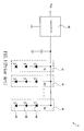
- FIG. 3 is a circuit diagram of a preferred embodiment of the invention.
- Referring to FIG. 2 for a light emitting diode car lamp apparatus of the invention, the light emitting diode
car lamp apparatus 1 comprises acontrol circuit 10 and a light emitting module 20 (such as a tail lamp module), and thecontrol circuit 10 with a tolerance (such as a conditional content) is coupled separately to a power supply unit 30 (such as a battery) and thelight emitting module 20. Thelight emitting module 20 detects a detected value (such as a current value or a voltage different value), and thelight emitting module 20 includes a plurality of LED units 21 (such as LED lamp strings), and theLED units 21 are connected in parallel and jointly connected to thecontrol circuit 10 in series. If theLED unit 21 fails and loses its light emitting characteristic, the detected value of thelight emitting module 20 will change. If theLED unit 21 breaks down and thecontrol circuit 10 discovers that the detected value does not match the tolerance, thecontrol circuit 10 will force the rest of theLED units 21 to lose all of their power supply as well as the light emitting characteristic, so that users can easily determine that theLED units 21 in the light emitting diodecar lamp apparatus 1 have lost their light emitting effect. - Referring to FIG. 2 for the present invention, the
control circuit 10 is divided into acontroller unit 11, an inducedresistor 12 and arelay unit 13, wherein thecontroller unit 11 is coupled to thepower supply unit 30 and sets a tolerance for a current value or a voltage difference value of a current passing through thelight emitting module 20 when several or all of theLED units 21 emit lights, and the inducedresistor 12 is coupled separately to thecontroller unit 11 and therelay unit 13 for detecting thelight emitting module 20 to obtain the detected value, and therelay unit 13 is coupled to thelight emitting module 20. If any one of theLED units 21 fails and cannot emit light, thecontroller unit 11 will compare the detected value obtained by the inducedresistor 12 with the tolerance. If the detected value does not match the tolerance, therelay unit 13 will disconnect the power supply of thelight emitting module 20, so that thelight emitting module 20 and thecontrol circuit 10 form a break circuit, and all of theLED units 21 lose their light emitting characteristic. - Referring to FIG. 3 for a preferred embodiment of the present invention, the
controller unit 11 is a microcontroller unit having a plurality of pins connected externally, wherein the pins include afirst pin 111, asecond pin 112, and athird pin 113, and thefirst pin 111 is coupled to thepower supply unit 30, and thefirst pin 111 andsecond pin 112 are coupled to both ends of the inducedresistor 12 for transmitting back an input value and an output value respectively and comparing the input value and output value from thefirst pin 111 andsecond pin 112 to obtain the detected value. If thecontroller unit 11 finds out that the detected value obtained from both ends of the inducedresistor 12 does not match the tolerance, thecontroller unit 11 will drive therelay unit 13 to disconnect the power supply of thelight emitting module 20, so that thelight emitting module 20 and thecontrol circuit 10 form a break circuit, and all of theLED units 21 lose their light emitting characteristic. - The
third pin 113 is coupled to therelay unit 13 for noticing therelay unit 13 to disconnect the power supply of thelight emitting module 20. Referring to FIG. 3 again, therelay unit 13 includes arelay switch 131 and aloop control element 132, and therelay switch 131 is installed between thelight emitting module 20 and the inducedresistor 12, and theloop control element 132 is coupled separately to therelay switch 131 and thethird pin 113, and theloop control element 132 can receive a notice from thethird pin 113 to issue a start signal to therelay switch 131 to drive thelight emitting module 20 and thecontrol circuit 10 to form a break circuit. - In this embodiment, the
light emitting module 20 includes five sets of LED units connected in parallel with each other and eachLED unit 21 includes five light emitting diodes (LEDs) 211 such as LED bulbs connected in series with each other. If anyLED 211 of anLED unit 21 breaks down and goes out, then theLED 211 of itsrespective LED unit 21 will not work anymore and lose its light emitting characteristic. By then, thecontroller unit 11 will compare the current value (which is the detected value) transmitted back from thefirst pin 111 and thesecond pin 112 with a current value (which is the tolerance) of a current passing through thelight emitting module 20, if not all of theLED units 21 emit light, and thecontroller unit 11 will send a start signal from thethird pin 113 through theloop control element 132 to enable therelay switch 131, so that therelay switch 131 will disconnect the power supply of thelight emitting module 20, and the rest four set ofLED units 21 connected in parallel with each other will lose their light emitting characteristic as well. - Assumed that the brightness of the three
LED units 21 out of the five sets ofLED units 21 connected in parallel with each other of thelight emitting module 20 according to the embodiment as shown in FIG. 3 meets the safe driving requirements, or thelight emitting module 20 has any two sets of failedLED units 21, the rest three sets ofLED units 21 still can continue working, and thus providing a brightness in compliance with the safe driving requirements. Therefore, it is not necessary to replace theLED units 21 immediately. If any one of theLED units 21 goes out, the rest four sets of theLED units 21 will be forced to lose their light emitting characteristic. Therefore, another preferred embodiment of the invention is disclosed further to overcome the inflexible arrangement of the previous embodiment. In FIG. 2, the tolerance can be set as a current value or a voltage difference value of a current passing through thelight emitting module 20 when a specific quantity ofLED units 21 emit light, and the specific quantity is the quantity required for the brightness in compliance with the safe driving requirements, and thus the detected valued obtained by thecontroller unit 11 from both ends of the inducedresistor 12 does not match the tolerance, and thethird pin 113 will send the start signal to therelay unit 13 to disconnect the power supply of thelight emitting module 20. For example, if any two of theLED units 21 breaks down and cannot emit light, the detected value will remain within the range of the tolerance. In other words, thecontroller unit 11 still will not drive therelay unit 13 to disconnect the power supply of thelight emitting module 20. Therefore, the present invention just needs to identify whether or not the light emitting diodecar lamp apparatus 1 emits light to determine a proper operation of the light emitting diodecar lamp apparatus 1, so as to provide a convenient and easy way to determine the light brightness and timely maintain or replace the car lamp. - It is worth pointing out that the present invention can be applied to a tail lamp of a transportation means, such that if a small quantity of
LED units 21 of the tail lamp breaks down, the whole tail lamp will be forced to stop its operating function, and thus providing drivers a convenient and easy way to determine whether or not the light emitting diodecar lamp apparatus 1 is working properly. Thecontrol circuit 10 is only a general conceptual name used in the invention, and any measure or element used for detecting the change of the power supply of thelight emitting module 20 to force thelight emitting module 20 to lose their light emitting function is covered by the scope of the claims of this invention. - While the invention has been described by means of specific embodiments, numerous modifications and variations could be made thereto by those skilled in the art without departing from the scope and spirit of the invention set forth in the claims.
Claims (11)
- A light emitting diode car lamp apparatus, comprising:a light emitting module, coupled to a power supply unit and having a plurality of light emitting diode units connected in parallel with each other, and said each light emitting diode unit including a plurality of light emitting diodes connected in series with each other; anda control circuit, installed between said power supply unit and said light emitting module and set therein a tolerance for detecting said light emitting module and obtaining a detected value, said control circuit will disconnect the power supply of said light emitting module if said detected value does not match said tolerance.
- The light emitting diode car lamp apparatus of claim 1, wherein said control circuit comprises:an induced resistor, installed in said control circuit, for detecting said light emitting module to obtain said detected value;a relay unit, coupled separately to said induced resistor and said light emitting module and capable of disconnecting the power supply of said light emitting module to form a break circuit between said light emitting module and said control circuit; anda controller unit, coupled separately to said power supply unit and said induced resistor, and setting a tolerance, and comparing a detected value obtained by said induced resistor with said tolerance, and if said detected value does not match said tolerance, then said relay unit will form a break circuit between said light emitting module and said control circuit.
- The light emitting diode car lamp apparatus of claim 2, wherein said controller unit is a microcontroller unit having a plurality of externally connected pins, and said pin comprising:a first pin, coupled to said power supply unit and a first end of said induced resistor for transmitting an input value back to said first end;a second pin, coupled to a second end of said induced resistor for transmitting an output value back to said second end; anda third pin, coupled to said relay unit for noticing said relay unit to form a break circuit between said light emitting module and said control circuit.
- The light emitting diode car lamp apparatus of claim 3, wherein said relay unit comprises:a relay switch, installed between said light emitting module and said induced resistor for forming a break circuit between said light emitting module and said control circuit after obtaining a start signal; anda loop control element, coupled separately to said relay switch and said third pin, for sending said start signal to said relay switch when a notice is received from said third pin.
- The light emitting diode car lamp apparatus of claim 4, wherein said controller unit compares said input value and said output value to produce said detected value.
- The light emitting diode car lamp apparatus of claim 5, wherein said input value, said output value and said detected value are current values.
- The light emitting diode car lamp apparatus of claim 5, wherein said input value, said output value and said detected value are voltage difference values.
- The light emitting diode car lamp apparatus of claim 6, wherein said tolerance is a current value of a current passing through said light emitting module when all of said LED units emit light.
- The light emitting diode car lamp apparatus of claim 7, wherein said tolerance is a voltage difference value of a current passing through said light emitting module when all of said LED units emit light.
- The light emitting diode car lamp apparatus of claim 6, wherein said tolerance is a current value of a current passing through said light emitting module when a plurality of LED units do not emit light.
- The light emitting diode car lamp apparatus of claim 7, wherein said tolerance is a voltage difference of a current passing through said light emitting module when a plurality of LED units do not emit light.
Priority Applications (1)
| Application Number | Priority Date | Filing Date | Title |
|---|---|---|---|
| EP06007263A EP1843639A1 (en) | 2006-04-06 | 2006-04-06 | LED car lamp apparatus |
Applications Claiming Priority (1)
| Application Number | Priority Date | Filing Date | Title |
|---|---|---|---|
| EP06007263A EP1843639A1 (en) | 2006-04-06 | 2006-04-06 | LED car lamp apparatus |
Publications (1)
| Publication Number | Publication Date |
|---|---|
| EP1843639A1 true EP1843639A1 (en) | 2007-10-10 |
Family
ID=36926822
Family Applications (1)
| Application Number | Title | Priority Date | Filing Date |
|---|---|---|---|
| EP06007263A Withdrawn EP1843639A1 (en) | 2006-04-06 | 2006-04-06 | LED car lamp apparatus |
Country Status (1)
| Country | Link |
|---|---|
| EP (1) | EP1843639A1 (en) |
Cited By (4)
| Publication number | Priority date | Publication date | Assignee | Title |
|---|---|---|---|---|
| DE102009029930B3 (en) * | 2009-06-19 | 2010-11-25 | Heraeus Noblelight Gmbh | Method for detecting loss of LED in parallelly connected LED chains utilized in industrial processes to produce UV light for hardening adhesive, involves comparing total current value with standard value to detect loss of LEDs in LED chains |
| JP5266594B1 (en) * | 2012-10-25 | 2013-08-21 | 株式会社エム・システム技研 | LED lamp, lighting device including the LED lamp, and LED lamp current control method |
| US20130304304A1 (en) * | 2010-10-26 | 2013-11-14 | Automotive Lighting Reutlingen Gmbh | Combination of an on-board power supply control device and at least one light control device of a motor vehicle |
| CN108534089A (en) * | 2018-04-12 | 2018-09-14 | 上海小糸车灯有限公司 | Daytime running lamps coordinated signals strategy and daytime running lamps |
Citations (7)
| Publication number | Priority date | Publication date | Assignee | Title |
|---|---|---|---|---|
| US6236331B1 (en) * | 1998-02-20 | 2001-05-22 | Newled Technologies Inc. | LED traffic light intensity controller |
| US20020140380A1 (en) * | 2001-03-28 | 2002-10-03 | Patent-Treuhand-Gesellschaft Fur Elektrische Gluhlampen Mbh | Drive circuit for an LED array |
| US20030025465A1 (en) * | 1999-12-23 | 2003-02-06 | Stmicroelectronics, Inc. | LED driver circuit and method |
| US6570505B1 (en) * | 1997-12-30 | 2003-05-27 | Gelcore Llc | LED lamp with a fault-indicating impedance-changing circuit |
| WO2004057924A1 (en) * | 2002-12-19 | 2004-07-08 | Koninklijke Philips Electronics N.V. | Leds driver |
| US20050116665A1 (en) * | 2003-09-09 | 2005-06-02 | Pentair Pool Products, Inc. | Controller circuit |
| WO2005079121A2 (en) * | 2004-02-11 | 2005-08-25 | Peter Bhagat | Apparatus for the control of lighting and associated methods |
-
2006
- 2006-04-06 EP EP06007263A patent/EP1843639A1/en not_active Withdrawn
Patent Citations (7)
| Publication number | Priority date | Publication date | Assignee | Title |
|---|---|---|---|---|
| US6570505B1 (en) * | 1997-12-30 | 2003-05-27 | Gelcore Llc | LED lamp with a fault-indicating impedance-changing circuit |
| US6236331B1 (en) * | 1998-02-20 | 2001-05-22 | Newled Technologies Inc. | LED traffic light intensity controller |
| US20030025465A1 (en) * | 1999-12-23 | 2003-02-06 | Stmicroelectronics, Inc. | LED driver circuit and method |
| US20020140380A1 (en) * | 2001-03-28 | 2002-10-03 | Patent-Treuhand-Gesellschaft Fur Elektrische Gluhlampen Mbh | Drive circuit for an LED array |
| WO2004057924A1 (en) * | 2002-12-19 | 2004-07-08 | Koninklijke Philips Electronics N.V. | Leds driver |
| US20050116665A1 (en) * | 2003-09-09 | 2005-06-02 | Pentair Pool Products, Inc. | Controller circuit |
| WO2005079121A2 (en) * | 2004-02-11 | 2005-08-25 | Peter Bhagat | Apparatus for the control of lighting and associated methods |
Cited By (10)
| Publication number | Priority date | Publication date | Assignee | Title |
|---|---|---|---|---|
| DE102009029930B3 (en) * | 2009-06-19 | 2010-11-25 | Heraeus Noblelight Gmbh | Method for detecting loss of LED in parallelly connected LED chains utilized in industrial processes to produce UV light for hardening adhesive, involves comparing total current value with standard value to detect loss of LEDs in LED chains |
| US20130304304A1 (en) * | 2010-10-26 | 2013-11-14 | Automotive Lighting Reutlingen Gmbh | Combination of an on-board power supply control device and at least one light control device of a motor vehicle |
| US9308821B2 (en) * | 2010-10-26 | 2016-04-12 | Automotive Lighting Reutlingen Gmbh | Internal power supply control device having at least one lighting control device for a motor vehicle |
| JP5266594B1 (en) * | 2012-10-25 | 2013-08-21 | 株式会社エム・システム技研 | LED lamp, lighting device including the LED lamp, and LED lamp current control method |
| WO2014064813A1 (en) * | 2012-10-25 | 2014-05-01 | 株式会社エム・システム技研 | Led lamp, lighting device including led lamp, and method for controlling electric current of led lamp |
| CN103907209A (en) * | 2012-10-25 | 2014-07-02 | 爱模系统有限公司 | LED lamp, lighting device including LED lamp, and method for controlling electric current of LED lamp |
| US8779679B2 (en) | 2012-10-25 | 2014-07-15 | M-System Co., Ltd. | LED lamp, illumination device including the LED lamp and current control method of the LED lamp |
| EP2793276A4 (en) * | 2012-10-25 | 2015-09-23 | M system co ltd | Led lamp, lighting device including led lamp, and method for controlling electric current of led lamp |
| CN103907209B (en) * | 2012-10-25 | 2015-10-21 | 爱模系统有限公司 | LED, comprise the lighting device of this LED and the current control method of LED |
| CN108534089A (en) * | 2018-04-12 | 2018-09-14 | 上海小糸车灯有限公司 | Daytime running lamps coordinated signals strategy and daytime running lamps |
Similar Documents
| Publication | Publication Date | Title |
|---|---|---|
| JP5576892B2 (en) | LED lighting and disconnection detection control device | |
| US11372039B2 (en) | Trailer lighting outage detection circuit | |
| JP5576891B2 (en) | LED lighting and disconnection detection control device | |
| CN102892241A (en) | Control circuit for dual-function signaling or lighting device and corresponding control method | |
| WO2010097864A1 (en) | Headlamp light source-lighting device, alarm device and communication device | |
| JP2009302295A (en) | Light-emitting diode driving device and illumination device for vehicle | |
| JP5809701B2 (en) | Lighting system | |
| EP1843639A1 (en) | LED car lamp apparatus | |
| KR102213684B1 (en) | Turn signal lamp and the method of variable sequential lighting | |
| JP4923197B2 (en) | Vehicle lighting | |
| US20070057676A1 (en) | Pulse shunt that allows for the use of light emitting diodes in vehicles that have a pulsed lamp check function in their external lighting system and/or trailers connected thereto | |
| CA3017474C (en) | Rail signal arrangement for a rail signalling system | |
| JP2011162008A (en) | Led lighting device for head lamp | |
| US7576493B2 (en) | Vehicle LED lamp controller used in low temperature environment | |
| KR200307889Y1 (en) | Error searcher or indicator of LED lamp | |
| KR20120004441U (en) | LED Traffic signal lamp | |
| KR20180041982A (en) | Lamp recognition type current controlling apparatus, and method thereof | |
| US9622311B1 (en) | Sub-assembly for searchlight signal, and associated assembly | |
| CN111225467A (en) | Car light auto-change over device and vehicle that has it | |
| JP4259259B2 (en) | Indicator light device with multiple LEDs | |
| JP6808415B2 (en) | Power supply | |
| CN109839604A (en) | Disconnected core detection circuit and power supply device | |
| JP4277643B2 (en) | Indicator light device with multiple LEDs | |
| JP2002076439A (en) | Connecting structure of led lamp | |
| KR101520340B1 (en) | Led lighting device having a self diagnosis function |
Legal Events
| Date | Code | Title | Description |
|---|---|---|---|
| PUAI | Public reference made under article 153(3) epc to a published international application that has entered the european phase |
Free format text: ORIGINAL CODE: 0009012 |
|
| AK | Designated contracting states |
Kind code of ref document: A1 Designated state(s): AT BE BG CH CY CZ DE DK EE ES FI FR GB GR HU IE IS IT LI LT LU LV MC NL PL PT RO SE SI SK TR |
|
| AX | Request for extension of the european patent |
Extension state: AL BA HR MK YU |
|
| 17P | Request for examination filed |
Effective date: 20071017 |
|
| AKX | Designation fees paid |
Designated state(s): AT BE BG CH CY CZ DE DK EE ES FI FR GB GR HU IE IS IT LI LT LU LV MC NL PL PT RO SE SI SK TR |
|
| 17Q | First examination report despatched |
Effective date: 20080624 |
|
| STAA | Information on the status of an ep patent application or granted ep patent |
Free format text: STATUS: THE APPLICATION IS DEEMED TO BE WITHDRAWN |
|
| 18D | Application deemed to be withdrawn |
Effective date: 20090324 |