EP1842323B1 - Dual-mode detection of powered device in power over ethernet system - Google Patents
Dual-mode detection of powered device in power over ethernet system Download PDFInfo
- Publication number
- EP1842323B1 EP1842323B1 EP06717528.1A EP06717528A EP1842323B1 EP 1842323 B1 EP1842323 B1 EP 1842323B1 EP 06717528 A EP06717528 A EP 06717528A EP 1842323 B1 EP1842323 B1 EP 1842323B1
- Authority
- EP
- European Patent Office
- Prior art keywords
- force
- detection
- voltage
- mode
- current
- Prior art date
- Legal status (The legal status is an assumption and is not a legal conclusion. Google has not performed a legal analysis and makes no representation as to the accuracy of the status listed.)
- Active
Links
- 238000001514 detection method Methods 0.000 title claims description 139
- 230000004044 response Effects 0.000 claims description 19
- 238000000034 method Methods 0.000 claims description 18
- 238000012360 testing method Methods 0.000 claims description 13
- 239000000523 sample Substances 0.000 claims description 9
- 238000012358 sourcing Methods 0.000 claims description 3
- 230000004048 modification Effects 0.000 description 4
- 238000012986 modification Methods 0.000 description 4
- 230000005540 biological transmission Effects 0.000 description 2
- 238000010586 diagram Methods 0.000 description 2
- 238000005259 measurement Methods 0.000 description 2
- 230000001419 dependent effect Effects 0.000 description 1
- 238000003032 molecular docking Methods 0.000 description 1
- 230000006855 networking Effects 0.000 description 1
- 238000010200 validation analysis Methods 0.000 description 1
Images


Classifications
-
- H—ELECTRICITY
- H04—ELECTRIC COMMUNICATION TECHNIQUE
- H04B—TRANSMISSION
- H04B3/00—Line transmission systems
- H04B3/02—Details
- H04B3/44—Arrangements for feeding power to a repeater along the transmission line
-
- H—ELECTRICITY
- H04—ELECTRIC COMMUNICATION TECHNIQUE
- H04L—TRANSMISSION OF DIGITAL INFORMATION, e.g. TELEGRAPHIC COMMUNICATION
- H04L49/00—Packet switching elements
- H04L49/35—Switches specially adapted for specific applications
- H04L49/351—Switches specially adapted for specific applications for local area network [LAN], e.g. Ethernet switches
-
- H—ELECTRICITY
- H04—ELECTRIC COMMUNICATION TECHNIQUE
- H04L—TRANSMISSION OF DIGITAL INFORMATION, e.g. TELEGRAPHIC COMMUNICATION
- H04L12/00—Data switching networks
- H04L12/02—Details
- H04L12/10—Current supply arrangements
-
- H—ELECTRICITY
- H04—ELECTRIC COMMUNICATION TECHNIQUE
- H04L—TRANSMISSION OF DIGITAL INFORMATION, e.g. TELEGRAPHIC COMMUNICATION
- H04L12/00—Data switching networks
- H04L12/28—Data switching networks characterised by path configuration, e.g. LAN [Local Area Networks] or WAN [Wide Area Networks]
-
- H—ELECTRICITY
- H02—GENERATION; CONVERSION OR DISTRIBUTION OF ELECTRIC POWER
- H02H—EMERGENCY PROTECTIVE CIRCUIT ARRANGEMENTS
- H02H3/00—Emergency protective circuit arrangements for automatic disconnection directly responsive to an undesired change from normal electric working condition with or without subsequent reconnection ; integrated protection
- H02H3/12—Emergency protective circuit arrangements for automatic disconnection directly responsive to an undesired change from normal electric working condition with or without subsequent reconnection ; integrated protection responsive to underload or no-load
Definitions
- This disclosure relates to power supply systems, and more particularly, to circuitry and methodology for detection of a Powered Device (PD) in a Power over Ethernet (PoE) system.
- PD Powered Device
- PoE Power over Ethernet
- Ethernet has become the most commonly used method for local area networking.
- IEEE 802.3 group the originator of the Ethernet standard, has developed an extension to the standard, known as IEEE 802.3af, that defines supplying power over Ethernet cabling.
- IEEE 802.3af defines a Power over Ethernet (PoE) system that involves delivering power over unshielded twisted-pair wiring from Power Sourcing Equipment (PSE) to a Powered Device (PD) located at opposite sides of a link.
- PSE Power Sourcing Equipment
- PD Powered Device
- network devices such as IP phones, wireless LAN access points, personal computers and Web cameras, have required two connections: one to a LAN and another to a power supply system.
- the PoE system eliminates the need for additional outlets and wiring to supply power to network devices. Instead, power is supplied over Ethernet cabling used for data transmission.
- PSE and PD are non-data entities allowing network devices to supply and draw power using the same generic cabling as is used for data transmission.
- a PSE is the equipment electrically specified at the point of the physical connection to the cabling, that provides the power to a link.
- a PSE is typically associated with an Ethernet switch, router, hub or other network switching equipment or midspan device.
- a PD is a device that is either drawing power or requesting power. PDs may be associated with such devices as digital IP telephones, wireless network access points, PDA or notebook computer docking stations, cell phone chargers and HVAC thermostats.
- PSE's main functions are to search the link for a PD requesting power, optionally classify the PD, supply power to the link if a PD is detected, monitor the power on the link, and disconnect power when it is no longer requested or required.
- a PD participates in the PD detection procedure by presenting detection signature to request power.
- the PD detection signature has electrical characteristics measured by the PSE.
- the PSE may probe its port with two voltages in the range from 2.8V to 10V with at least a 1V voltage difference to determine a signature resistance of the PD.
- the signature resistance in the range from 19KOhm to 26.5KOhm is considered to be a valid detection signature.
- EP 1 221 783 A1 relates to a remote power feed device for supplying a remote power feed to a terminal in a telecommunication netwok which includes a first resistor and a second resistor in parallel with the first resistor. It compares the voltage at the terminal of the first resistor with a first threshold voltage and the voltage at the terminals of the second resistor with a second threshold voltage.
- the PSE can erroneously consider a non-PoE device to be a PD. The PSE may then attempt to power this device causing damage if the device cannot tolerate the applied power.
- the present disclosure offers novel circuitry and methodology for detecting a Powered Device (PD) in a system for providing power to the PD that includes PD detection circuitry for detecting the PD in a first mode by providing detection current to probe the PD, and for detecting the PD in a second mode by providing detection voltage to probe the PD.
- a control circuit determines that the PD is a valid device if the PD is detected both in the first mode and in the second mode.
- the PD detection circuitry may comprise a force-current detection circuit for operating in the first mode and the force-voltage detection circuit for operating in the second mode.
- a Power Sourcing Equipment (PSE) in a Power over Ethernet (PoE) system may comprise a PD detection source for detecting a PD in a force-current mode and in a force-voltage mode, and a control circuit for validating the PD if the PD is detected in both the force-current mode and the force-voltage mode.
- PSE Power Sourcing Equipment
- PoE Power over Ethernet
- the PD detection source may comprise a force-current detection circuit for producing detection current to probe the PD in the force-current mode, and the force-voltage detection circuit for producing detection voltage to probe the PD in the force-voltage mode.
- the control circuit may control the force-current detection circuit to determine the signature resistance in the force-current mode, and may control the force-voltage detection circuit to determine the signature resistance in the force-voltage mode
- the prescribed parameter of the PD may include prescribed resistance in the PD.
- the force-voltage mode may be carried out by probing the PD with test voltage of a prescribed value.
- the force-current mode may be carried out by probing the PD with test current corresponding to the test voltage of the prescribed value.
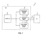
- FIG. 1 shows a simplified block-diagram of a PD detection system 10 of the present disclosure in a PoE system comprising a PSE 12, and a PD 14 connectable to the PSE 12 via a link 16, such as a 2-wire link defined in the IEEE 802.3af standard.
- the PD detection system 10 includes a force-voltage detection source 18, a force-current detection source 20, a switching circuit 22 and a controller 24 that may be arranged in the PSE 12.
- the force-current detection source 20 produces detection current Idet that corresponds to detection voltage Vdet in a pre-defined valid voltage range.
- the valid Vdet voltage range may be from 2.8V to 10V, as specified in the IEEE 802.3af standard.
- the source resistance Rsc may be in the range from 100KOhm to 100MOhm.
- the minimum current difference between values of the detection current Idet produced for different detection tests corresponds to a Vdet voltage difference of 1V.
- FIG. 4 is a flow chart illustrating a control algorithm carried out by the controller 24 to control the PD detection system 10.
- the controller 24 may be a state machine or a microcontroller arranged in the PSE 12. After a PD detection procedure is initiated (step 102), the controller 24 may switch the PD detection system 10 into a force-current mode. In this mode, the controller 24 controls the force-current detection source 20 to apply detection current I 1 to the PD 14 and measure voltage V 1 produced in response to the detection current I 1 (step 104). Thereafter, the controller 24 commands the force-current detection source 20 to apply detection current I 2 to the PD 14 and measure voltage V 2 produced in response to the detection current I 2 (step 106).
- the controller 24 determines that the signature resistance Rsig is valid, it still cannot make a conclusion as to whether the PD 14 is a device compliant with the IEEE 802.3af standard. For example, if the signature resistance of the PD 14 or PoE line changes during the measurement of response voltages, or if the PD 14 has a non-linear resistance in the range of detection values, the controller 24 can erroneously consider the PD 14 to be a device compliant with the IEEE 802.3af standard. The PSE 12 may then attempt to power this device causing damage if the device cannot tolerate the applied power.
- the controller 24 switches the PD detection system 10 in a force-voltage mode of operation to further validate the detected PD.
- the PD detection procedure of the present disclosure begins with the force-current detection mode because this mode enables the PD detection system 10 to better reject noise associated with the PoE line, to provide more accurate signature resistance determination. Hence, a non-compliant PD may be rejected after performing detection in the initial detection mode.
- the force-voltage detection mode may be carried out before the force-current detection mode.
- the controller 24 controls the force-voltage detection source 18 to apply detection voltage V 3 to the PD 14 and measure current I 3 produced in response to the detection voltage V 3 (step 114). Thereafter, the controller 24 controls the force-voltage detection source 18 to apply detection voltage V 4 to the PD 14 and measure current I 4 produced in response to the detection voltage V 4 (step 116).
- the pre-defined range for the signature resistance in the force-voltage mode may coincide with this range in the force-current mode.
- the controller 24 concludes that the PD 24 is not a PD compliant with the IEEE 802.3af standard and terminates the detection procedure (step 112). However, if the signature resistance Rsig is within the pre-defined range, the PD 14 is validated (step 120).
- further PD detection procedures may be carried out in the force-current detection mode and/or in the force-voltage detection mode to further reduce likelihood of a false detection.
- the PSE 12 may perform a classification procedure to determine a class of the PD 14 and provide the PD 14 with requested amount of power.
Landscapes
- Engineering & Computer Science (AREA)
- Computer Networks & Wireless Communication (AREA)
- Signal Processing (AREA)
- Small-Scale Networks (AREA)
- Power Sources (AREA)
- Communication Control (AREA)
- Cable Transmission Systems, Equalization Of Radio And Reduction Of Echo (AREA)
Description
- This application claims priority of provisional
U.S. patent application No. 60/646,509 filed on January 25,2005 - This disclosure relates to power supply systems, and more particularly, to circuitry and methodology for detection of a Powered Device (PD) in a Power over Ethernet (PoE) system.
- Over the years, Ethernet has become the most commonly used method for local area networking. The IEEE 802.3 group, the originator of the Ethernet standard, has developed an extension to the standard, known as IEEE 802.3af, that defines supplying power over Ethernet cabling. The IEEE 802.3af standard defines a Power over Ethernet (PoE) system that involves delivering power over unshielded twisted-pair wiring from Power Sourcing Equipment (PSE) to a Powered Device (PD) located at opposite sides of a link. Traditionally, network devices such as IP phones, wireless LAN access points, personal computers and Web cameras, have required two connections: one to a LAN and another to a power supply system. The PoE system eliminates the need for additional outlets and wiring to supply power to network devices. Instead, power is supplied over Ethernet cabling used for data transmission.
- As defined in the IEEE 802.3af standard, PSE and PD are non-data entities allowing network devices to supply and draw power using the same generic cabling as is used for data transmission. A PSE is the equipment electrically specified at the point of the physical connection to the cabling, that provides the power to a link. A PSE is typically associated with an Ethernet switch, router, hub or other network switching equipment or midspan device. A PD is a device that is either drawing power or requesting power. PDs may be associated with such devices as digital IP telephones, wireless network access points, PDA or notebook computer docking stations, cell phone chargers and HVAC thermostats.
- PSE's main functions are to search the link for a PD requesting power, optionally classify the PD, supply power to the link if a PD is detected, monitor the power on the link, and disconnect power when it is no longer requested or required. A PD participates in the PD detection procedure by presenting detection signature to request power. The PD detection signature has electrical characteristics measured by the PSE.
- In particular, the PSE may probe its port with two voltages in the range from 2.8V to 10V with at least a 1V voltage difference to determine a signature resistance of the PD. The signature resistance in the range from 19KOhm to 26.5KOhm is considered to be a valid detection signature.
-
EP 1 221 783 A1 relates to a remote power feed device for supplying a remote power feed to a terminal in a telecommunication netwok which includes a first resistor and a second resistor in parallel with the first resistor. It compares the voltage at the terminal of the first resistor with a first threshold voltage and the voltage at the terminals of the second resistor with a second threshold voltage. - "Amendment: Data Terminal Equipment (DTE) Power via Media Dependent Interface (MDI)" is based on the standard IEEE Std 802.3-2002 plus changes incorporated by IEEE Std 802.3ae-2002. The document relates to PD detection, PSE validations circuits, and PSE detections of PDs.
- However, if the signature resistance or line changes during the measurement or if a device being detected has a non-linear resistance in the range from 2.8V to 10V, the PSE can erroneously consider a non-PoE device to be a PD. The PSE may then attempt to power this device causing damage if the device cannot tolerate the applied power.
- Therefore, there is a need for a PD detection scheme that would reduce the likelihood of a false PD detection.
- The present disclosure offers novel circuitry and methodology for detecting a Powered Device (PD) in a system for providing power to the PD that includes PD detection circuitry for detecting the PD in a first mode by providing detection current to probe the PD, and for detecting the PD in a second mode by providing detection voltage to probe the PD. A control circuit determines that the PD is a valid device if the PD is detected both in the first mode and in the second mode.
- In accordance with one aspect of the disclosure, the PD detection circuitry may determine prescribed resistance in the PD by measuring voltage produced in response to the detection current in the first mode, and by measuring current produced in response to the detection voltage in the second mode.
- In accordance with an embodiment of the disclosure, the PD detection circuitry may comprise a force-current detection circuit for operating in the first mode and the force-voltage detection circuit for operating in the second mode.
- The PD may be considered to be a valid device, if it is detected sequentially in the first mode and in the second mode. The first mode of detection may be carried out before the second mode. The control circuit may control the PD detection circuitry to switch it between the first and second modes.
- In accordance with another aspect of the disclosure, a Power Sourcing Equipment (PSE) in a Power over Ethernet (PoE) system may comprise a PD detection source for detecting a PD in a force-current mode and in a force-voltage mode, and a control circuit for validating the PD if the PD is detected in both the force-current mode and the force-voltage mode.
- The PD detection source may comprise a force-current detection circuit for producing detection current to probe the PD in the force-current mode, and the force-voltage detection circuit for producing detection voltage to probe the PD in the force-voltage mode.
- Signature resistance of the PD may be determined by the force-current detection circuit by measuring voltage produced in response to the detection current, and by the force-voltage detection circuit by measuring current produced in response to the detection voltage.
- The control circuit may control the force-current detection circuit to determine the signature resistance in the force-current mode, and may control the force-voltage detection circuit to determine the signature resistance in the force-voltage mode
- In accordance with a method of the present disclosure the following steps are carried out to detect a PD:
- determining a prescribed parameter of the PD in a force-current mode,
- determining the prescribed parameter of the PD in a force-voltage mode, and
- validating the PD if the prescribed parameter of the PD is found to be valid in both the force-current mode and the force-voltage mode.
- The prescribed parameter of the PD may include prescribed resistance in the PD.
- The force-voltage mode may be carried out by probing the PD with test voltage of a prescribed value. The force-current mode may be carried out by probing the PD with test current corresponding to the test voltage of the prescribed value.
- Additional advantages and aspects of the disclosure will become readily apparent to those skilled in the art from the following detailed description, wherein embodiments of the present disclosure are shown and described, simply by way of illustration of the best mode contemplated for practicing the present disclosure. As will be described, the disclosure is capable of other and different embodiments, and its several details are susceptible of modification in various obvious respects, all without departing from the spirit of the disclosure. Accordingly, the drawings and description are to be regarded as illustrative in nature, and not as limitative.
- The following detailed description of the embodiments of the present disclosure can best be understood when read in conjunction with the following drawings, in which the features are not necessarily drawn to scale but rather are drawn as to best illustrate the pertinent features, wherein:
-
FIG. 1 is a block diagram illustrating an exemplary system for detecting a PD in accordance with the present disclosure. -
FIG. 2 is a Thevenin equivalent circuit of a force-voltage detection source. -
FIG. 3 is a Norton equivalent circuit of a force-current detection source. -
FIG. 4 is a flow chart illustrating a control algorithm for controlling operations of the system for detecting a PD in a force-current detection mode and in a force-voltage detection mode. - The present disclosure will be made with the example of detecting a PD in PoE system. It will become apparent, however, that the concepts described herein are applicable to recognizing any connectable device provided with power in a power supply system.
-
FIG. 1 shows a simplified block-diagram of aPD detection system 10 of the present disclosure in a PoE system comprising aPSE 12, and aPD 14 connectable to thePSE 12 via alink 16, such as a 2-wire link defined in the IEEE 802.3af standard. ThePD detection system 10 includes a force-voltage detection source 18, a force-current detection source 20, aswitching circuit 22 and acontroller 24 that may be arranged in thePSE 12. - The force-
voltage detection source 18 provides detection of thePD 14 in a force-voltage mode.FIG. 2 illustrates a Thevenin equivalent circuit of the force-voltage detection source 18 that includes avoltage source 32, source resistance Rsv connected in series with thevoltage source 32, and acurrent monitor 34 connected in parallel to the source resistance Rsv. - The force-
voltage detection source 18 produces detection voltage Vdet for detecting a PD. For example, the detection voltage Vdet may be produced in the range from 2.8V to 10V, as specified in the IEEE 802.3af standard. The source resistance Rsv may be up to 100KOhm. - In the force-voltage mode, the force-
voltage detection source 18 may perform two or more tests to detect signature resistance of thePD 14. For each test, the force-voltage detection source 18 produces the detection voltage Vdet at its output terminals Vdet+ and Vdet-. The minimum voltage difference between the detection voltages Vdet produced for different detection tests is 1V. - Via the switching
circuit 22, the detection voltage Vdet is applied to detection circuitry of thePD 14 including the PD signature resistance Rsig. Thecurrent monitor 34 determines current Ires produced in response to the applied detection voltage Vdet. The signature resistance Rsig of thePD 14 in the force-voltage mode of PD detection is determined as
where ΔVdet is a difference between detection voltages in different tests, and ΔIres is a difference between currents produced in response to the respective detection voltages. - The signature resistance Rsig of a PD should be in a pre-defined range. For example, for a PD compliant with the IEEE 802.3af standard, the signature resistance must be in the range from 19KOhm to 26.5KOm.
- The force-
current detection source 20 provides detection of thePD 14 in a force-current detection mode.FIG. 3 shows a Norton equivalent circuit of the force-current detection source 20 that comprises acurrent source 42, source resistance Rsc connected in parallel to thecurrent source 42, and avoltage monitor 44 connected in parallel to the source resistance Rsc. - In each test for detecting the
PD 14, the force-current detection source 20 produces detection current Idet that corresponds to detection voltage Vdet in a pre-defined valid voltage range. For example, the valid Vdet voltage range may be from 2.8V to 10V, as specified in the IEEE 802.3af standard. The source resistance Rsc may be in the range from 100KOhm to 100MOhm. The minimum current difference between values of the detection current Idet produced for different detection tests corresponds to a Vdet voltage difference of 1V. - Via the switching
circuit 22, the detection current Idet is supplied to the detection circuitry of thePD 14 including the PD signature resistance Rsig. The voltage monitor 34 determines voltage Vres produced in response to the supplied detection current Idet. The signature resistance Rsig of thePD 14 in the force-current mode of PD detection is determined as
where ΔIdet is a difference between detection currents in different tests, and ΔVres is a difference between voltages produced in response to the respective detection currents. - The switching
circuit 22 coupled between thePoE link 16 and output terminals of thedetection sources controller 24 to supply the detection voltage Vdet from the force-voltage detection source 18 to thePoE link 16 in the force-voltage mode of operation, and to supply the detection current Idet from the force-current detection source 20 to thePoE link 16 in the force-current mode. Also, the switchingcircuit 22 transfers to the force-voltage source 18 or the force-current detection source 20 the current or voltage produced in response to the respective detection voltage or current in the force-voltage or force-current mode, respectively. -
FIG. 4 is a flow chart illustrating a control algorithm carried out by thecontroller 24 to control thePD detection system 10. Thecontroller 24 may be a state machine or a microcontroller arranged in thePSE 12. After a PD detection procedure is initiated (step 102), thecontroller 24 may switch thePD detection system 10 into a force-current mode. In this mode, thecontroller 24 controls the force-current detection source 20 to apply detection current I1 to thePD 14 and measure voltage V1 produced in response to the detection current I1 (step 104). Thereafter, thecontroller 24 commands the force-current detection source 20 to apply detection current I2 to thePD 14 and measure voltage V2 produced in response to the detection current I2 (step 106). - Based on the applied values of detection current and determined values of response voltage, the
controller 24 calculates the signature resistance Rsig of thePD 14 as follows: Rsig = (V2 - V1)/(I2 - I1) (step 108). Then, thecontroller 24 determines whether the signature resistance is a valid value, i.e. whether the signature resistance is within a predefined range (step 110). For example, to validate a PD compliant with the IEEE 802.3af standard, thecontroller 24 determines whether the signature resistance is within the range from 19KOhm to 26.5KOm. - If the calculated signature resistance Rsig is not a valid value, the
controller 24 concludes that thePD 14 is not a device compliant with the IEEE 802.3af standard and terminates the detection procedure (step 112). - If the
controller 24 determines that the signature resistance Rsig is valid, it still cannot make a conclusion as to whether thePD 14 is a device compliant with the IEEE 802.3af standard. For example, if the signature resistance of thePD 14 or PoE line changes during the measurement of response voltages, or if thePD 14 has a non-linear resistance in the range of detection values, thecontroller 24 can erroneously consider thePD 14 to be a device compliant with the IEEE 802.3af standard. ThePSE 12 may then attempt to power this device causing damage if the device cannot tolerate the applied power. - Therefore, the
controller 24 switches thePD detection system 10 in a force-voltage mode of operation to further validate the detected PD. The PD detection procedure of the present disclosure begins with the force-current detection mode because this mode enables thePD detection system 10 to better reject noise associated with the PoE line, to provide more accurate signature resistance determination. Hence, a non-compliant PD may be rejected after performing detection in the initial detection mode. However, the force-voltage detection mode may be carried out before the force-current detection mode. - In the force-voltage detection mode, the
controller 24 controls the force-voltage detection source 18 to apply detection voltage V3 to thePD 14 and measure current I3 produced in response to the detection voltage V3 (step 114). Thereafter, thecontroller 24 controls the force-voltage detection source 18 to apply detection voltage V4 to thePD 14 and measure current I4 produced in response to the detection voltage V4 (step 116). - Then, the
controller 24 calculates the signature resistance Rsig of thePD 14 as follows: Rsig = (V4 - V3)/(I4 - I3), and determines whether the calculated signature resistance is within a predefined range, i.e. a valid value (step 118). The pre-defined range for the signature resistance in the force-voltage mode may coincide with this range in the force-current mode. - If the calculated signature resistance Rsig is not a valid value, the
controller 24 concludes that thePD 24 is not a PD compliant with the IEEE 802.3af standard and terminates the detection procedure (step 112). However, if the signature resistance Rsig is within the pre-defined range, thePD 14 is validated (step 120). - Before the
PD 14 is considered to be a valid device, further PD detection procedures may be carried out in the force-current detection mode and/or in the force-voltage detection mode to further reduce likelihood of a false detection. - After validating the
PD 14, thePSE 12 may perform a classification procedure to determine a class of thePD 14 and provide thePD 14 with requested amount of power. - The foregoing description illustrates and describes aspects of the present invention. Additionally, the disclosure shows and describes only preferred embodiments, but as aforementioned, it is to be understood that the invention is capable of use in various other combinations, modifications, and environments and is capable of changes or modifications within the scope of the inventive concept as expressed herein, commensurate with the above teachings, and/or the skill or knowledge of the relevant art.
- The embodiments described hereinabove are further intended to explain best modes known of practicing the invention and to enable others skilled in the art to utilize the invention in such, or other, embodiments and with the various modifications required by the particular applications or uses of the invention.
- Accordingly, the description is not intended to limit the invention to the form disclosed herein. Also, it is intended that the appended claims be construed to include alternative embodiments.
Claims (20)
- A system for providing power to a Powered Device, PD, (14) comprising:PD detection circuitry for detecting the PD (14) in a force-current mode by providing detection current to probe the PD (14), and in a force-voltage mode by providing detection voltage to probe the PD (14), anda control circuit (24) for determining that the PD (14) is a valid device if the PD (14) is detected both in the force-current mode and in the force-voltage mode.
- The system of claim 1, wherein the PD detection circuitry is configured for determining voltage produced in response to the detection current in the force-current mode, and for determining current produced in response to the detection voltage in the force-voltage mode.
- The system of claim 1, wherein the PD detection circuitry comprises a force-current detection circuit (20) for operating in the first-current mode and a force-voltage detection circuit (18) for operating in the force-voltage mode.
- The system of claim 1, wherein the PD detection circuitry is configured to determine prescribed resistance in the PD (14) in the force-current mode and in the force-voltage mode.
- The system of claim 1, wherein the PD detection circuitry is configured to detect the PD (14) sequentially in the force-current mode and in the force-voltage mode.
- The system of claim 5, wherein the PD detection circuitry is controlled to detect the PD (14) in the force-current mode before detecting the PD (14) in the force-voltage mode.
- The system of claim 1, wherein the control circuit (24) is configured to control the PD detection circuitry to operate in the force-current and force-voltage modes.
- A Power Sourcing Equipment, PSE, in a Power over Ethernet, PoE, system, comprising:a PD detection source for detecting a PD (14) in a force-current mode and a force-voltage mode, anda control circuit (24) for validating the PD (14) if the PD (14) is detected in both the force-current mode and the force-voltage mode.
- The PSE of claim 8, wherein the PD detection source comprises a force-current detection circuit (20) for producing detection current to probe the PD (14) in the force-current mode, and the force-voltage detection circuit (18) for producing detection voltage to probe the PD (14) in the force-voltage mode.
- The PSE of claim 9, wherein the force-current detection circuit (20) is configured for determining voltage produced in response to the detection current, and the force-voltage detection circuit (18) is configured for determining current produced in response to the detection voltage.
- The PSE of claim 8, wherein the PD detection source is configured to determine signature resistance in the force-current mode and the force-voltage mode.
- The PSE of claim 8, wherein the PD detection source is configured to detect the PD (14) sequentially in the force-current mode and the force-voltage mode.
- The PSE of claim 8, wherein the PD detection source is configured to detect the PD (14) in the force-current mode before detecting the PD (14) in the force-voltage mode.
- The PSE of claim 8, wherein the control circuit (24) is configured for controlling the PD (14) detection source to operate in the force-current mode and the force-voltage mode.
- A method of detecting a PD (14), comprising the steps of:determining a prescribed parameter of the PD (14) in a force-current mode,determining the prescribed parameter of the PD (14) in a force-voltage mode, andvalidating the PD (14) if the prescribed parameter of the PD (14) is found to be valid in both the force-current mode and the force-voltage mode.
- The method of claim 15, wherein the prescribed parameter of the PD (14) includes prescribed resistance in the PD (14).
- The method of claim 15, wherein the force-current mode and the force-voltage mode are carried out sequentially.
- The method of claim 15, wherein the force-current mode is carried out before the force-voltage mode.
- The method of claim 15, wherein the force-voltage mode is carried out by probing the PD (14) with test voltage of a prescribed value.
- The method of claim 19, wherein the force-current mode is carried out by probing the PD (14) with test current corresponding to the test voltage of the prescribed value.
Applications Claiming Priority (3)
| Application Number | Priority Date | Filing Date | Title |
|---|---|---|---|
| US64650905P | 2005-01-25 | 2005-01-25 | |
| US11/252,624 US7613936B2 (en) | 2005-01-25 | 2005-10-19 | Dual-mode detection of powered device in power over ethernet system |
| PCT/US2006/000343 WO2006081046A2 (en) | 2005-01-25 | 2006-01-09 | Dual-mode detection of powered device in power over ethernet system |
Publications (2)
| Publication Number | Publication Date |
|---|---|
| EP1842323A2 EP1842323A2 (en) | 2007-10-10 |
| EP1842323B1 true EP1842323B1 (en) | 2015-03-18 |
Family
ID=36696514
Family Applications (1)
| Application Number | Title | Priority Date | Filing Date |
|---|---|---|---|
| EP06717528.1A Active EP1842323B1 (en) | 2005-01-25 | 2006-01-09 | Dual-mode detection of powered device in power over ethernet system |
Country Status (5)
| Country | Link |
|---|---|
| US (1) | US7613936B2 (en) |
| EP (1) | EP1842323B1 (en) |
| JP (1) | JP4598084B2 (en) |
| KR (1) | KR101214773B1 (en) |
| WO (1) | WO2006081046A2 (en) |
Families Citing this family (17)
| Publication number | Priority date | Publication date | Assignee | Title |
|---|---|---|---|---|
| US8213141B2 (en) | 2006-01-17 | 2012-07-03 | Broadcom Corporation | Power over Ethernet electrostatic discharge protection circuit |
| US7631201B2 (en) * | 2006-05-25 | 2009-12-08 | Foundry Networks, Inc. | System software for managing power allocation to Ethernet ports in the absence of mutually exclusive detection and powering cycles in hardware |
| US7774628B2 (en) * | 2006-05-25 | 2010-08-10 | Foundry Networks, Inc. | Enabling/disabling power-over-ethernet software subsystem in response to power supply status |
| EP1903653B1 (en) * | 2006-08-31 | 2018-09-26 | Avago Technologies General IP (Singapore) Pte. Ltd. | Over-voltage protection for power and data applications |
| US7557549B2 (en) * | 2006-11-21 | 2009-07-07 | Honeywell International Inc. | Automatic output mode select for an actuator controller |
| US8250381B2 (en) | 2007-03-30 | 2012-08-21 | Brocade Communications Systems, Inc. | Managing power allocation to ethernet ports in the absence of mutually exclusive detection and powering cycles in hardware |
| WO2008136028A1 (en) | 2007-05-08 | 2008-11-13 | Stmicroelectronics S.R.L. | Method of discrimination of a device as powerable through a lan line and device for estimating electric parameters of a lan line |
| US8301922B2 (en) * | 2009-07-31 | 2012-10-30 | Broadcom Corporation | System and method for policing bad powered devices in power over ethernet |
| WO2011067177A1 (en) * | 2009-12-04 | 2011-06-09 | Osram Gesellschaft mit beschränkter Haftung | A method for controlling the operation of an electronic converter, and a corresponding electronic converter, lighting system and software product |
| CN102714597B (en) * | 2010-01-31 | 2015-11-25 | 惠普发展公司,有限责任合伙企业 | For alleviating the method that wrong power receiving equipment detects |
| US20110219244A1 (en) * | 2010-03-05 | 2011-09-08 | Hsi-Mien Wu | Power extracting system and a splitter |
| WO2012028979A1 (en) * | 2010-09-02 | 2012-03-08 | Koninklijke Philips Electronics N.V. | Apparatus for powering an electrical consumer via a data connection. |
| TWI432740B (en) | 2012-03-30 | 2014-04-01 | Wistron Corp | Test board, test system and test method for power over ethernet device |
| US9334063B2 (en) | 2012-09-10 | 2016-05-10 | Rosemount Aerospace, Inc. | Aircraft avionics tablet interface module |
| US9859951B2 (en) | 2013-11-26 | 2018-01-02 | Linear Technology Corporation | Power over data lines detection and classification scheme |
| TWI584611B (en) * | 2015-11-24 | 2017-05-21 | 九暘電子股份有限公司 | Inspection device and method for powered devices in a Power over Ethernet system |
| CN113595745A (en) | 2016-10-13 | 2021-11-02 | 华为技术有限公司 | Power supply equipment, Ethernet power supply method and device |
Family Cites Families (14)
| Publication number | Priority date | Publication date | Assignee | Title |
|---|---|---|---|---|
| JPH07301646A (en) * | 1994-05-02 | 1995-11-14 | Matsushita Electric Ind Co Ltd | Printed circuit board inspecting device |
| JP3383590B2 (en) * | 1998-08-19 | 2003-03-04 | 沖電気工業株式会社 | Power supply system for LAN compatible telephone terminals |
| US6473608B1 (en) * | 1999-01-12 | 2002-10-29 | Powerdsine Ltd. | Structure cabling system |
| US6571181B1 (en) * | 1999-08-11 | 2003-05-27 | Broadcom Corporation | System and method for detecting a device requiring power |
| FR2815215B1 (en) * | 2000-10-05 | 2003-01-31 | Cit Alcatel | TERMINAL SUITABLE FOR LOCAL POWER SUPPLY AND TO BE REMOTE POWERED THROUGH A LINK CONNECTING TO A LOCAL AREA NETWORK |
| FR2819364B1 (en) * | 2001-01-08 | 2003-04-11 | Cit Alcatel | DEVICE FOR TELEALING A TERMINAL IN A TELECOMMUNICATION NETWORK, CONCENTRATOR, AND REPEATER COMPRISING SUCH A DEVICE |
| US6459275B1 (en) * | 2001-02-28 | 2002-10-01 | Avaya Technology Corp. | Detection of devices on a local area network |
| JP2002290490A (en) * | 2001-03-28 | 2002-10-04 | Sony Corp | Electronic device |
| TW200501551A (en) | 2003-04-23 | 2005-01-01 | Rohm Co Ltd | Audio signal amplifier circuit and electronic apparatus having the same |
| US7849343B2 (en) * | 2003-06-10 | 2010-12-07 | Microsemi Corp. - Analog Mixed Signal Group Ltd. | Pre-detection of powered devices |
| US7356588B2 (en) * | 2003-12-16 | 2008-04-08 | Linear Technology Corporation | Circuits and methods for detecting the presence of a powered device in a powered network |
| US8074084B2 (en) * | 2004-11-03 | 2011-12-06 | Cisco Technology, Inc. | Powered device classification in a wired data telecommunications network |
| US7248097B2 (en) * | 2004-09-02 | 2007-07-24 | Micrel, Inc. | Voltage-activated, constant current sink circuit |
| US7599485B2 (en) * | 2005-06-24 | 2009-10-06 | Cisco Technology, Inc. | Communications system employing single-pair identity circuit for remotely powered device |
-
2005
- 2005-10-19 US US11/252,624 patent/US7613936B2/en active Active
-
2006
- 2006-01-09 JP JP2007552156A patent/JP4598084B2/en active Active
- 2006-01-09 KR KR1020077019059A patent/KR101214773B1/en active IP Right Grant
- 2006-01-09 WO PCT/US2006/000343 patent/WO2006081046A2/en active Application Filing
- 2006-01-09 EP EP06717528.1A patent/EP1842323B1/en active Active
Non-Patent Citations (1)
| Title |
|---|
| "Amendment: Data Terminal Equipment (DTE) Power via Media Media Dependent Interface (MDI) ; D4_01Diff_1_18", IEEE DRAFT; D4_01DIFF_1_18, IEEE-SA, PISCATAWAY, NJ USA, vol. 802.3af, 19 January 2003 (2003-01-19), pages 1 - 148, XP068013786 * |
Also Published As
| Publication number | Publication date |
|---|---|
| US20060164775A1 (en) | 2006-07-27 |
| WO2006081046A3 (en) | 2006-12-14 |
| JP2008529352A (en) | 2008-07-31 |
| WO2006081046A2 (en) | 2006-08-03 |
| KR20070101338A (en) | 2007-10-16 |
| KR101214773B1 (en) | 2012-12-21 |
| EP1842323A2 (en) | 2007-10-10 |
| US7613936B2 (en) | 2009-11-03 |
| JP4598084B2 (en) | 2010-12-15 |
Similar Documents
| Publication | Publication Date | Title |
|---|---|---|
| EP1842323B1 (en) | Dual-mode detection of powered device in power over ethernet system | |
| EP1842324B1 (en) | Detecting legacy powered device in power over ethernet system | |
| US7230412B2 (en) | Distinguishing network interface card from short circuit condition in power over ethernet system | |
| EP1842321B1 (en) | Power sourcing equipment having auto-zero circuit for determining and controlling output current | |
| KR101224712B1 (en) | System for Providing Power over Communication Cable Having Mechanism for Determining Resistance of Communication Cable | |
| US20060164098A1 (en) | Utilization of power delivered to powered device during detection and classification mode | |
| JP4454665B2 (en) | Common-mode data transmission for Power over Ethernet systems | |
| US20060212724A1 (en) | System and method for supporting operations of advanced power over ethernet system | |
| US20060168459A1 (en) | Providing data communication between power supply device and powered device in system for supplying power over communication link | |
| CN101124775A (en) | Dual-mode detection of powered device in power over Ethernet system | |
| EP1864429A2 (en) | Combination of high-side and low-side current sensing in system for providing power over communication link |
Legal Events
| Date | Code | Title | Description |
|---|---|---|---|
| PUAI | Public reference made under article 153(3) epc to a published international application that has entered the european phase |
Free format text: ORIGINAL CODE: 0009012 |
|
| 17P | Request for examination filed |
Effective date: 20070725 |
|
| AK | Designated contracting states |
Kind code of ref document: A2 Designated state(s): AT BE BG CH CY CZ DE DK EE ES FI FR GB GR HU IE IS IT LI LT LU LV MC NL PL PT RO SE SI SK TR |
|
| DAX | Request for extension of the european patent (deleted) | ||
| 17Q | First examination report despatched |
Effective date: 20090626 |
|
| RAP1 | Party data changed (applicant data changed or rights of an application transferred) |
Owner name: LINEAR TECHNOLOGY CORPORATION |
|
| REG | Reference to a national code |
Ref country code: DE Ref legal event code: R079 Ref document number: 602006044819 Country of ref document: DE Free format text: PREVIOUS MAIN CLASS: H04L0012100000 Ipc: H02H0003120000 |
|
| GRAP | Despatch of communication of intention to grant a patent |
Free format text: ORIGINAL CODE: EPIDOSNIGR1 |
|
| RIC1 | Information provided on ipc code assigned before grant |
Ipc: H04L 12/10 20060101ALI20141021BHEP Ipc: H04L 12/931 20130101ALI20141021BHEP Ipc: H02H 3/12 20060101AFI20141021BHEP |
|
| INTG | Intention to grant announced |
Effective date: 20141113 |
|
| GRAS | Grant fee paid |
Free format text: ORIGINAL CODE: EPIDOSNIGR3 |
|
| GRAA | (expected) grant |
Free format text: ORIGINAL CODE: 0009210 |
|
| AK | Designated contracting states |
Kind code of ref document: B1 Designated state(s): AT BE BG CH CY CZ DE DK EE ES FI FR GB GR HU IE IS IT LI LT LU LV MC NL PL PT RO SE SI SK TR |
|
| REG | Reference to a national code |
Ref country code: GB Ref legal event code: FG4D |
|
| REG | Reference to a national code |
Ref country code: CH Ref legal event code: EP |
|
| REG | Reference to a national code |
Ref country code: IE Ref legal event code: FG4D |
|
| REG | Reference to a national code |
Ref country code: AT Ref legal event code: REF Ref document number: 717110 Country of ref document: AT Kind code of ref document: T Effective date: 20150415 |
|
| REG | Reference to a national code |
Ref country code: DE Ref legal event code: R096 Ref document number: 602006044819 Country of ref document: DE Effective date: 20150423 |
|
| REG | Reference to a national code |
Ref country code: NL Ref legal event code: T3 |
|
| PG25 | Lapsed in a contracting state [announced via postgrant information from national office to epo] |
Ref country code: FI Free format text: LAPSE BECAUSE OF FAILURE TO SUBMIT A TRANSLATION OF THE DESCRIPTION OR TO PAY THE FEE WITHIN THE PRESCRIBED TIME-LIMIT Effective date: 20150318 Ref country code: SE Free format text: LAPSE BECAUSE OF FAILURE TO SUBMIT A TRANSLATION OF THE DESCRIPTION OR TO PAY THE FEE WITHIN THE PRESCRIBED TIME-LIMIT Effective date: 20150318 Ref country code: LT Free format text: LAPSE BECAUSE OF FAILURE TO SUBMIT A TRANSLATION OF THE DESCRIPTION OR TO PAY THE FEE WITHIN THE PRESCRIBED TIME-LIMIT Effective date: 20150318 |
|
| REG | Reference to a national code |
Ref country code: AT Ref legal event code: MK05 Ref document number: 717110 Country of ref document: AT Kind code of ref document: T Effective date: 20150318 |
|
| REG | Reference to a national code |
Ref country code: LT Ref legal event code: MG4D |
|
| PG25 | Lapsed in a contracting state [announced via postgrant information from national office to epo] |
Ref country code: GR Free format text: LAPSE BECAUSE OF FAILURE TO SUBMIT A TRANSLATION OF THE DESCRIPTION OR TO PAY THE FEE WITHIN THE PRESCRIBED TIME-LIMIT Effective date: 20150619 Ref country code: LV Free format text: LAPSE BECAUSE OF FAILURE TO SUBMIT A TRANSLATION OF THE DESCRIPTION OR TO PAY THE FEE WITHIN THE PRESCRIBED TIME-LIMIT Effective date: 20150318 |
|
| PG25 | Lapsed in a contracting state [announced via postgrant information from national office to epo] |
Ref country code: CZ Free format text: LAPSE BECAUSE OF FAILURE TO SUBMIT A TRANSLATION OF THE DESCRIPTION OR TO PAY THE FEE WITHIN THE PRESCRIBED TIME-LIMIT Effective date: 20150318 Ref country code: PT Free format text: LAPSE BECAUSE OF FAILURE TO SUBMIT A TRANSLATION OF THE DESCRIPTION OR TO PAY THE FEE WITHIN THE PRESCRIBED TIME-LIMIT Effective date: 20150720 Ref country code: RO Free format text: LAPSE BECAUSE OF FAILURE TO SUBMIT A TRANSLATION OF THE DESCRIPTION OR TO PAY THE FEE WITHIN THE PRESCRIBED TIME-LIMIT Effective date: 20150318 Ref country code: SK Free format text: LAPSE BECAUSE OF FAILURE TO SUBMIT A TRANSLATION OF THE DESCRIPTION OR TO PAY THE FEE WITHIN THE PRESCRIBED TIME-LIMIT Effective date: 20150318 Ref country code: ES Free format text: LAPSE BECAUSE OF FAILURE TO SUBMIT A TRANSLATION OF THE DESCRIPTION OR TO PAY THE FEE WITHIN THE PRESCRIBED TIME-LIMIT Effective date: 20150318 Ref country code: EE Free format text: LAPSE BECAUSE OF FAILURE TO SUBMIT A TRANSLATION OF THE DESCRIPTION OR TO PAY THE FEE WITHIN THE PRESCRIBED TIME-LIMIT Effective date: 20150318 |
|
| PG25 | Lapsed in a contracting state [announced via postgrant information from national office to epo] |
Ref country code: IS Free format text: LAPSE BECAUSE OF FAILURE TO SUBMIT A TRANSLATION OF THE DESCRIPTION OR TO PAY THE FEE WITHIN THE PRESCRIBED TIME-LIMIT Effective date: 20150718 Ref country code: AT Free format text: LAPSE BECAUSE OF FAILURE TO SUBMIT A TRANSLATION OF THE DESCRIPTION OR TO PAY THE FEE WITHIN THE PRESCRIBED TIME-LIMIT Effective date: 20150318 Ref country code: PL Free format text: LAPSE BECAUSE OF FAILURE TO SUBMIT A TRANSLATION OF THE DESCRIPTION OR TO PAY THE FEE WITHIN THE PRESCRIBED TIME-LIMIT Effective date: 20150318 |
|
| REG | Reference to a national code |
Ref country code: DE Ref legal event code: R097 Ref document number: 602006044819 Country of ref document: DE |
|
| PLBE | No opposition filed within time limit |
Free format text: ORIGINAL CODE: 0009261 |
|
| STAA | Information on the status of an ep patent application or granted ep patent |
Free format text: STATUS: NO OPPOSITION FILED WITHIN TIME LIMIT |
|
| REG | Reference to a national code |
Ref country code: FR Ref legal event code: PLFP Year of fee payment: 11 |
|
| PG25 | Lapsed in a contracting state [announced via postgrant information from national office to epo] |
Ref country code: DK Free format text: LAPSE BECAUSE OF FAILURE TO SUBMIT A TRANSLATION OF THE DESCRIPTION OR TO PAY THE FEE WITHIN THE PRESCRIBED TIME-LIMIT Effective date: 20150318 |
|
| 26N | No opposition filed |
Effective date: 20151221 |
|
| PG25 | Lapsed in a contracting state [announced via postgrant information from national office to epo] |
Ref country code: SI Free format text: LAPSE BECAUSE OF FAILURE TO SUBMIT A TRANSLATION OF THE DESCRIPTION OR TO PAY THE FEE WITHIN THE PRESCRIBED TIME-LIMIT Effective date: 20150318 |
|
| PG25 | Lapsed in a contracting state [announced via postgrant information from national office to epo] |
Ref country code: BE Free format text: LAPSE BECAUSE OF NON-PAYMENT OF DUE FEES Effective date: 20160131 |
|
| PG25 | Lapsed in a contracting state [announced via postgrant information from national office to epo] |
Ref country code: LU Free format text: LAPSE BECAUSE OF FAILURE TO SUBMIT A TRANSLATION OF THE DESCRIPTION OR TO PAY THE FEE WITHIN THE PRESCRIBED TIME-LIMIT Effective date: 20160109 Ref country code: BE Free format text: LAPSE BECAUSE OF FAILURE TO SUBMIT A TRANSLATION OF THE DESCRIPTION OR TO PAY THE FEE WITHIN THE PRESCRIBED TIME-LIMIT Effective date: 20150318 |
|
| REG | Reference to a national code |
Ref country code: CH Ref legal event code: PL |
|
| PG25 | Lapsed in a contracting state [announced via postgrant information from national office to epo] |
Ref country code: MC Free format text: LAPSE BECAUSE OF FAILURE TO SUBMIT A TRANSLATION OF THE DESCRIPTION OR TO PAY THE FEE WITHIN THE PRESCRIBED TIME-LIMIT Effective date: 20150318 |
|
| PG25 | Lapsed in a contracting state [announced via postgrant information from national office to epo] |
Ref country code: CH Free format text: LAPSE BECAUSE OF NON-PAYMENT OF DUE FEES Effective date: 20160131 Ref country code: LI Free format text: LAPSE BECAUSE OF NON-PAYMENT OF DUE FEES Effective date: 20160131 |
|
| REG | Reference to a national code |
Ref country code: IE Ref legal event code: MM4A |
|
| REG | Reference to a national code |
Ref country code: FR Ref legal event code: PLFP Year of fee payment: 12 |
|
| PG25 | Lapsed in a contracting state [announced via postgrant information from national office to epo] |
Ref country code: IE Free format text: LAPSE BECAUSE OF NON-PAYMENT OF DUE FEES Effective date: 20160109 |
|
| REG | Reference to a national code |
Ref country code: FR Ref legal event code: PLFP Year of fee payment: 13 |
|
| PG25 | Lapsed in a contracting state [announced via postgrant information from national office to epo] |
Ref country code: HU Free format text: LAPSE BECAUSE OF FAILURE TO SUBMIT A TRANSLATION OF THE DESCRIPTION OR TO PAY THE FEE WITHIN THE PRESCRIBED TIME-LIMIT; INVALID AB INITIO Effective date: 20060109 Ref country code: CY Free format text: LAPSE BECAUSE OF FAILURE TO SUBMIT A TRANSLATION OF THE DESCRIPTION OR TO PAY THE FEE WITHIN THE PRESCRIBED TIME-LIMIT Effective date: 20150318 |
|
| PG25 | Lapsed in a contracting state [announced via postgrant information from national office to epo] |
Ref country code: TR Free format text: LAPSE BECAUSE OF FAILURE TO SUBMIT A TRANSLATION OF THE DESCRIPTION OR TO PAY THE FEE WITHIN THE PRESCRIBED TIME-LIMIT Effective date: 20150318 |
|
| PG25 | Lapsed in a contracting state [announced via postgrant information from national office to epo] |
Ref country code: BG Free format text: LAPSE BECAUSE OF FAILURE TO SUBMIT A TRANSLATION OF THE DESCRIPTION OR TO PAY THE FEE WITHIN THE PRESCRIBED TIME-LIMIT Effective date: 20150318 |
|
| REG | Reference to a national code |
Ref country code: DE Ref legal event code: R082 Ref document number: 602006044819 Country of ref document: DE Representative=s name: MUELLER-BORE & PARTNER PATENTANWAELTE PARTG MB, DE Ref country code: DE Ref legal event code: R081 Ref document number: 602006044819 Country of ref document: DE Owner name: ANALOG DEVICES INTERNATIONAL UNLIMITED COMPANY, IE Free format text: FORMER OWNER: LINEAR TECHNOLOGY CORP., MILPITAS, CALIF., US Ref country code: DE Ref legal event code: R082 Ref document number: 602006044819 Country of ref document: DE Representative=s name: WITHERS & ROGERS LLP, DE |
|
| REG | Reference to a national code |
Ref country code: DE Ref legal event code: R082 Ref document number: 602006044819 Country of ref document: DE Representative=s name: WITHERS & ROGERS LLP, DE |
|
| REG | Reference to a national code |
Ref country code: GB Ref legal event code: 732E Free format text: REGISTERED BETWEEN 20211118 AND 20211124 |
|
| REG | Reference to a national code |
Ref country code: NL Ref legal event code: PD Owner name: ANALOG DEVICES INTERNATIONAL UNLIMITED COMPANY; IE Free format text: DETAILS ASSIGNMENT: CHANGE OF OWNER(S), ASSIGNMENT; FORMER OWNER NAME: LINEAR TECHNOLOGY LLC Effective date: 20211216 |
|
| PGFP | Annual fee paid to national office [announced via postgrant information from national office to epo] |
Ref country code: IT Payment date: 20220103 Year of fee payment: 17 |
|
| PGFP | Annual fee paid to national office [announced via postgrant information from national office to epo] |
Ref country code: NL Payment date: 20221220 Year of fee payment: 18 Ref country code: GB Payment date: 20221221 Year of fee payment: 18 Ref country code: FR Payment date: 20221220 Year of fee payment: 18 |
|
| PGFP | Annual fee paid to national office [announced via postgrant information from national office to epo] |
Ref country code: DE Payment date: 20221220 Year of fee payment: 18 |
|
| PG25 | Lapsed in a contracting state [announced via postgrant information from national office to epo] |
Ref country code: IT Free format text: LAPSE BECAUSE OF NON-PAYMENT OF DUE FEES Effective date: 20230109 |