EP1840593A1 - Calibratable distance meter and method for calibrating such a meter - Google Patents
Calibratable distance meter and method for calibrating such a meter Download PDFInfo
- Publication number
- EP1840593A1 EP1840593A1 EP06111878A EP06111878A EP1840593A1 EP 1840593 A1 EP1840593 A1 EP 1840593A1 EP 06111878 A EP06111878 A EP 06111878A EP 06111878 A EP06111878 A EP 06111878A EP 1840593 A1 EP1840593 A1 EP 1840593A1
- Authority
- EP
- European Patent Office
- Prior art keywords
- distance
- rangefinder
- calibration
- radiation
- correction
- Prior art date
- Legal status (The legal status is an assumption and is not a legal conclusion. Google has not performed a legal analysis and makes no representation as to the accuracy of the status listed.)
- Withdrawn
Links
Images


Classifications
-
- G—PHYSICS
- G01—MEASURING; TESTING
- G01S—RADIO DIRECTION-FINDING; RADIO NAVIGATION; DETERMINING DISTANCE OR VELOCITY BY USE OF RADIO WAVES; LOCATING OR PRESENCE-DETECTING BY USE OF THE REFLECTION OR RERADIATION OF RADIO WAVES; ANALOGOUS ARRANGEMENTS USING OTHER WAVES
- G01S17/00—Systems using the reflection or reradiation of electromagnetic waves other than radio waves, e.g. lidar systems
- G01S17/02—Systems using the reflection of electromagnetic waves other than radio waves
- G01S17/06—Systems determining position data of a target
- G01S17/08—Systems determining position data of a target for measuring distance only
-
- G—PHYSICS
- G01—MEASURING; TESTING
- G01S—RADIO DIRECTION-FINDING; RADIO NAVIGATION; DETERMINING DISTANCE OR VELOCITY BY USE OF RADIO WAVES; LOCATING OR PRESENCE-DETECTING BY USE OF THE REFLECTION OR RERADIATION OF RADIO WAVES; ANALOGOUS ARRANGEMENTS USING OTHER WAVES
- G01S7/00—Details of systems according to groups G01S13/00, G01S15/00, G01S17/00
- G01S7/48—Details of systems according to groups G01S13/00, G01S15/00, G01S17/00 of systems according to group G01S17/00
- G01S7/497—Means for monitoring or calibrating
Definitions
- the invention relates to a calibratable distance measuring device according to the preamble of claim 1 and to a method for surface-specific calibration of a rangefinder according to the preamble of claim 8.
- movable or hand-held surveying equipment For these tasks stationary, movable or hand-held surveying equipment is used, which perform an optical distance measurement to a selected Aufyak. In most cases, a laser beam is emitted and received and evaluated again after reflection at the target. To determine the distance, different measurement principles are available, such as e.g. Phase or transit time measurement.
- portable and handheld devices are used which are applied with respect to a structure to be measured and then perform distance measurement to a surface.
- a suitable for such applications and typical surveying equipment is, for example, in the EP 0 738 899 and the EP 0 701 702 described.
- red lasers are mostly used as radiation sources for the distance measurement.
- distance meters of the prior art accuracies up to the millimeter range can be achieved with great ease of handling.
- the surfaces to be measured are often artificial or natural mineral surfaces, e.g. Stone or concrete walls. Especially in interior design measurements on plastic surfaces or foils or for example also to insulation and insulation materials are typical. Similar surfaces also occur in the field of industrial processes involving e.g. often has to be measured on plastic housing.
- the measuring radiation enters the surface and is scattered at different depths.
- the backscattered portion of the measurement radiation is then composed of contributions of different depths below the appropriate surface, so that the distance meter takes a comparatively larger distance.
- the measurement thus appears distorted.
- plastics eg polyethylene
- the error is 1-2 mm
- red Plastics and for red laser light 2-4 mm
- Candle material such as paraffin or stearin, leads to errors in the cm range.
- One object is to provide an improved rangefinder.
- a further object is to provide a rangefinder which allows correct and reproducible range measurements regardless of the surface to be measured.
- the invention is based on the fact that distance measurements are corrected surface-specifically by one or more calibration measurements or calibration data, eg in the simplest case by an offset determination.
- surface-specific or surface-characteristic adaptable correction functionalities are provided in the evaluation component used for the distance measurement of a generic rangefinder, which correct the influence of the respective surface or compensate for the falsification of the true distance caused thereby.
- Such customizable correction functionality is based on surface-specific data or correction parameters obtained either by calibration measurements over a known reference distance with the rangefinder, e.g. in a zero distance measurement device by measuring the zero distance and automatically correcting for the next measurement, or by importing a data.
- a data import can be used if planar surfaces of a known material with a typical or homogeneous structure are adequate.
- the correction parameters can be measured under laboratory conditions and subsequently made available in electronic or tabular form.
- a more flexible solution is the use of calibration measurements. This is particularly advantageous if atypical, specific or unknown surfaces or those without available datasets are adequate. Such specific surfaces are eg curved, very thin or angled surfaces. Unknown surfaces are also present, for example, if the uppermost layer is identifiable, but there is no clarity over underlying layers, so that the radiation is also inhomogeneous due to lower layers Ensembles is scattered. Again, with very thin structures, some of the radiation may pass through the material so that data sets for a thick medium would give false results.
- the stored difference thus serves as a correction value for the surface or material-specific retroreflectivity.
- This procedure is used in the Evaluation component provided a surface-specific calibrated correction functionality.
- the correction acts as a shift of the zero position, which can be done either on the level of the measured distance, ie after evaluation, or in the signal processing itself, ie on the basis of a correction of raw data, such as the time or phase shift.
- a simple offset correction can already reduce the error by more than a factor of 5.
- This approach thus uses a constant surface-specific correction functionality.
- the measurement error caused by the surface can also have a linear or nonlinear distance-dependent influence.
- the recorded values can be used as support points for generating a distance and surface-specific correction functionality for the distance measurements.
- the difference amount has a dependency on the distance.
- the corresponding correction function can be modeled linearly or nonlinearly, eg quadratically.
- an adaptation of the model can also be performed recursively by using a basic number of measurements to derive the correction function subsequent verification measurements will be adjusted step by step.
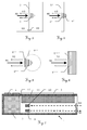
- the rangefinder 1 shows the representation of a generic rangefinder 1 in an external view.
- the rangefinder 1 has a housing 2, in which the necessary electronic components are arranged.
- the housing 2 is designed so that the rangefinder 1 held in the hand and can also be created defined or defined at a point to be measured.
- On the housing 2 corresponding abutment edges or fold-out or attachable stop elements may be appropriate for this purpose, as shown for example in the WO 02/50564 to be discribed.
- Through optical openings in the housing measuring radiation MS is emitted toward a surface to be measured in terms of their distance to the distance meter 1 and returned from this in turn as backscattered radiation RS, so that they can be received and evaluated by a receiving optics of the rangefinder 1.
- this typically has on its upper side a display device 3 and a keypad 4.
- Fig.2 illustrates the use of a generic rangefinder in a schematic representation.
- the generic rangefinder 1 shown in FIG. 1 is typically positioned in a defined manner for measurement with a contact edge. After the precise positioning, the distance measurement is carried out by emitting measurement radiation MS, in this example laser light, onto a surface 5, the portion of the laser light spot backscattered by the surface 5 being registered again by the rangefinder 1 as a zone of optical backscattering 6. In this example, a flush final system of the rangefinder takes place at an edge of a table 7. The visibility of the laser light spot can be done a simple determination of the measuring section. Although it can be assumed that the backscattered laser light is reflected solely by the uppermost layer of the surface 5, it has surprisingly been found that for many surface types of relevance in practice, contributions from deeper areas of the surface must also be taken into account.
- FIGS. 4-6 show further examples of distortions of distance measurements due to specific characteristics of surfaces.
- FIG. 5 A similar effect due to the surface shape is shown in Fig. 5 for a third example.
- the material of the surface to be measured 5 one sufficient thickness, but the entrance surface of the optical backscatter zone 6 "is no longer flat, but curved, so that compared to the plane case in some areas a brushesstreuanteil 8" is lost.
- a falsification of the distance measurement would take place in this situation.
- inhomogeneous materials as a fourth example of a structure of the surface material is illustrated in FIG.
- the material of the surfaces 5 "'to be measured now has two zones or layers with different optical parameters, so that within the zone of optical backscattering 6"' two different backscattering characteristics follow for the two zones. Even if the depth-dependent distribution of the individual contributions for the different materials or optical parameters is known, a falsification of the distance measurement would take place in this situation if the exact layer structure and the beam characteristic at the interface between the two zones are not known.
- the rangefinder 1 exemplarily designed as a handheld laser rangefinder comprises a housing 2 with a display device 3 and a keypad 4, wherein in the housing 2 a radiation source 9 for emitting laser light as measuring radiation MS, a radiation detector 10 for receiving the backscattered radiation from a surface RS and an evaluation component 11 for determination a distance of one or more selectable rangefinder related nullages to the surface.
- a zero position defines the point associated with the distance meter 1, from which a distance is calculated, and thus the reference value for the distance values output as the result.
- the evaluation component 11 is designed such that it has a correction function that can be calibrated specifically for the surface.
- a memory unit 12 can be assigned to it, in which surface-specific data recorded during calibration measurements are stored. In such a calibration measurement, a correction difference which is specific for the distance and surface area is determined and recorded in the memory unit 12, so that falsifications can be corrected in later measurements.
- Such surface-specific data can also be imported as data sets via an interface in the rangefinder 1 or manually entered via the keypad 4.
- the correction functionality may be designed to take account of the corruption on different stages of the signal processing.
- a shift in the zero position of the measured distance can take place, so that an apparent distance determined by the electronics about a surface-specific Difference is corrected so that the difference amount and / or the thus determined true distance displayed or output.
- a direct correction can be made on the level of the measured signal, for example by shifting the time zero position in a runtime meter or the zero position of the phase as a reference in a rangefinder according to the phase meter principle.
- the correction functionality can effect a distance-dependent correction of measured distance or measured signal.
- a function can be determined which enables a distance-dependent correction of the measured distance for a specific surface.
- a number of calibration measurements may be taken over defined, i. sufficiently precise and known distances are carried out, wherein a function is derived from the measured apparent distances and the known true distances as support points, which approximates the adulteration.
- Such functions can also be stored in the memory unit 12 or imported into it.
- FIGS. 8a-b schematically show a first example of the method according to the invention for calibrating a second exemplary embodiment of the rangefinder according to the invention in two variants Kalibrier horren to the specific surface 5 schematically illustrated.
- One way of providing a defined distance as a calibration distance is the use of a contact region of the housing 2 '. Due to the handling requirements housing 2 'of hand-held rangefinders 1' should be made compact, so that the settable by the housing distances are short. Thus, it makes sense to use a projection of the housing 2 'on the optics used for the measurement to define a measuring distance, when its contact area contacts the surface 5 to be measured.
- a variant of the second exemplary embodiment shown in FIG. 8a uses a calibration detector 10a and a contact area on the housing 2 'of the rangefinder 1', wherein the calibration detector 10a is arranged such that it detects backscattered radiation RS not detectable by the radiation detector 10 'in the near range and the investment area defines a calibration distance as a known distance.
- the calibration detector 10a is arranged at a position which is determined by the geometric conditions of the beam path or radiation reception when the housing 2 'bears against the surface 5.
- a second radiation detector is here Kalibrierumlenkelement used 10b, wherein this is arranged so that the radiation detector 10 'in the vicinity not detectable backscattered measuring radiation RS is deflected to the radiation detector 10'.
- suitable components are, for example, in the EP 701,702 described.
- a deployable calibration distance component 13 can be used which permits a precise definition of a distance to be measured via a graduation 14, possibly in conjunction with a grid
- the defined and known distance to be measured is determined by a fold-out calibration distance component 15.
- the defined state, i. the extended or deployed calibration distance component 13 or 15 are also detected electronically so that the true distance associated therewith is automatically available for calibration.
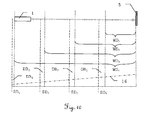
- FIG. 10 explains a second example of the method according to the invention for calibration in the case of distance-dependent falsification.
- a distance-dependent correction function 16 which is exemplified here by the representation of four measurements.
- a distance measurement is performed to the surface 5, which in each case delivers an apparent distance SD 1 -SD 4 .
- a difference amount DB 1 - DB 4 is calculated as the difference between the assigned true distance WD 1 -WD 4 and apparent distance SD 1 -SD 4 , which forms the basis for deriving the correction function 16.
- the correction function 16 is formed as a linear approximation of the distance-dependent difference amount, but according to the invention, functions of higher order, for example quadratic or polynomial approximations, are possible and realizable.
Landscapes
- Engineering & Computer Science (AREA)
- Physics & Mathematics (AREA)
- Remote Sensing (AREA)
- Computer Networks & Wireless Communication (AREA)
- General Physics & Mathematics (AREA)
- Radar, Positioning & Navigation (AREA)
- Electromagnetism (AREA)
- Length Measuring Devices By Optical Means (AREA)
- Optical Radar Systems And Details Thereof (AREA)
- Transition And Organic Metals Composition Catalysts For Addition Polymerization (AREA)
- Sampling And Sample Adjustment (AREA)
- Disintegrating Or Milling (AREA)
- Analysing Materials By The Use Of Radiation (AREA)
Abstract
Description
Die Erfindung betrifft ein kalibrierbares Entfernungsmessgerät nach dem Oberbegriff des Anspruchs 1 und ein Verfahren zum oberflächenspezifischen Kalibrieren eines Entfernungsmessers nach dem Oberbegriff des Anspruchs 8.The invention relates to a calibratable distance measuring device according to the preamble of
In vielen Anwendungen werden Verfahren und Systeme zur Entfernungsmessung verwendet. Beispiele hierfür sind ausgesprochen präzise Vermessungen in geodätischen Applikationen, aber auch Messaufgaben im Bereich der Bauinstallation oder für industrielle Prozesssteuerungen.In many applications, methods and systems for distance measurement are used. Examples include extremely precise measurements in geodetic applications, but also measuring tasks in the field of building installation or for industrial process control.
Für diese Aufgaben werden stationäre, bewegbare oder auch handhaltbare Vermessungsgeräte eingesetzt, welche eine optische Entfernungsmessung zu einem ausgewählten Aufpunkt ausführen. Zumeist wird hierbei ein Laserstrahl emittiert und nach Reflektion am Ziel wieder empfangen und ausgewertet. Zur Bestimmung der Entfernung stehen dabei verschiedene Messprinzipien zur Verfügung, wie z.B. Phasen- oder Laufzeitmessung.For these tasks stationary, movable or hand-held surveying equipment is used, which perform an optical distance measurement to a selected Aufpunkt. In most cases, a laser beam is emitted and received and evaluated again after reflection at the target. To determine the distance, different measurement principles are available, such as e.g. Phase or transit time measurement.
Insbesondere im Bereich der Bauinstallation oder Bauabnahme werden tragbare und in der Hand zu haltende Geräte verwendet, welche bezüglicher einer zu vermessenden Struktur angelegt werden und dann eine Entfernungsmessung zu einer Oberfläche durchführen. Ein für solche Anwendungen geeignetes und typisches Vermessungsgerät wird beispielsweise in der
Da für die meisten Anwendungen ein auf der anzumessenden Oberfläche sichtbarer Messpunkt vorteilhaft ist, werden zumeist rote Laser als Strahlungsquellen für die Entfernungsmessung verwendet. Mit Entfernungsmessern des Stands der Technik sind so bei grosser Handhabungsfreundlichkeit Genauigkeiten bis in den Millimeterbereich erzielbar.Since for most applications a measuring point visible on the surface to be measured is advantageous, red lasers are mostly used as radiation sources for the distance measurement. With distance meters of the prior art accuracies up to the millimeter range can be achieved with great ease of handling.
Bei den anzumessenden Oberflächen handelt es sich häufig um künstliche oder natürliche mineralische Oberflächen, wie z.B. Stein- oder Betonwände. Gerade im Innenausbau sind Messungen zu Kunststoffoberflächen bzw. -folien oder beispielsweise auch zu Dämm- und Isolationsmaterialien typisch. Ähnliche Oberflächen treten auch im Bereich der industriellen Prozesses auf, bei denen z.B. häufig auf Kunststoffgehäuse gemessen werden muss.The surfaces to be measured are often artificial or natural mineral surfaces, e.g. Stone or concrete walls. Especially in interior design measurements on plastic surfaces or foils or for example also to insulation and insulation materials are typical. Similar surfaces also occur in the field of industrial processes involving e.g. often has to be measured on plastic housing.
In gegenwärtigen und zukünftigen Anwendungsfeldern besteht dabei der Bedarf, verlässliche Messungen auch bis in den Submillimeterbereich zu realisieren. Überraschenderweise wurde aber erkannt, dass eine grosse Zahl von Oberflächen zur Verfälschung der Entfernungsmessung führen kann.In current and future fields of application, there is the need to realize reliable measurements down to the sub-millimeter range. Surprisingly, however, it was recognized that a large number of surfaces can lead to the falsification of the distance measurement.
Bei vielen Oberflächen tritt die Messstrahlung in die Oberfläche ein und wird in verschiedener Tiefe gestreut. Der zurückgestreute Anteil der Messstrahlung setzt sich dann aus Beiträgen unterschiedlicher Tiefe unter der angemessenen Oberfläche zusammen, so dass vom Entfernungsmesser eine vergleichsweise grössere Entfernung aufgenommen wird. Bezogen auf die gewünschte Entfernungsmessung zur Oberfläche erscheint die Messung somit verfälscht. So beträgt der Fehler beispielsweise bei Kunststoffen, z.B. Polyethylen, 1-2 mm, bei roten Kunststoffen und für rotes Laserlicht 2-4 mm, bei Styropor 5-6 mm. Kerzenmaterial, wie Paraffin bzw. Stearin, führt zu Fehlern im cm-Bereich.For many surfaces, the measuring radiation enters the surface and is scattered at different depths. The backscattered portion of the measurement radiation is then composed of contributions of different depths below the appropriate surface, so that the distance meter takes a comparatively larger distance. Based on the desired distance measurement to the surface, the measurement thus appears distorted. For example, for plastics, eg polyethylene, the error is 1-2 mm, for red Plastics and for red laser light 2-4 mm, for polystyrene 5-6 mm. Candle material, such as paraffin or stearin, leads to errors in the cm range.
Je nach Material, Form der Oberfläche und oberflächennaher Struktur können somit systematische Fehler die gemessenen Entfernungen beeinflussen. Dabei ist der Einfluss aufgrund der verschiedenen, auch nichtlinearen Wechselwirkungen wiederum abhängig von weiteren Grössen, wie z.B. dem Strahlprofil, dem Auftreffwinkel und der Intensität der Strahlung auf der Oberfläche.Depending on the material, the shape of the surface and the near-surface structure, systematic errors may influence the measured distances. The influence due to the various, even non-linear interactions is in turn dependent on other variables, such as. the beam profile, the angle of incidence and the intensity of the radiation on the surface.
Diese überraschende Erkenntnis weist darauf hin, dass Entfernungsmessungen mit einer reproduzierbaren Genauigkeit auch im Submillimeterbereich eine Berücksichtigung dieser Fehlereinflüsse erfordern.This surprising finding indicates that distance measurements with a reproducible accuracy even in the sub-millimeter range require consideration of these error influences.
Eine Aufgabe besteht darin, einen verbesserten Entfernungsmesser bereitzustellen.One object is to provide an improved rangefinder.
Eine weitere Aufgabe besteht darin, einen Entfernungsmesser bereitzustellen, welcher unabhängig von der anzumessenden Oberfläche korrekte und reproduzierbare Entfernungsmessungen ermöglicht.A further object is to provide a rangefinder which allows correct and reproducible range measurements regardless of the surface to be measured.
Diese Aufgaben werden durch die Gegenstände der Ansprüche 1, 8 oder der abhängigen Ansprüche gelöst bzw. die Lösungen weitergebildet.These objects are achieved by the subject-matter of
Die Erfindung beruht darauf, dass Entfernungsmessungen oberflächenspezifisch durch eine oder mehrere Kalibriermessungen oder Kalibrierdaten korrigiert werden, z.B. im einfachsten Fall durch eine Offsetbestimmung.The invention is based on the fact that distance measurements are corrected surface-specifically by one or more calibration measurements or calibration data, eg in the simplest case by an offset determination.
Hierfür werden in der zur Entfernungsmessung verwendeten Auswertekomponente eines gattungsgemässen Entfernungsmessers oberflächenspezifische bzw. an die Oberflächencharakteristik anpassbare Korrekturfunktionalitäten bereitgestellt, welche den Einfluss der jeweiligen Oberfläche korrigieren bzw. die hierdurch bewirkte Verfälschung der wahren Distanz kompensieren.For this purpose, surface-specific or surface-characteristic adaptable correction functionalities are provided in the evaluation component used for the distance measurement of a generic rangefinder, which correct the influence of the respective surface or compensate for the falsification of the true distance caused thereby.
Solche anpassbare Korrekturfunktionalitäten beruhen auf oberflächenspezifischen Daten oder Korrekturparametern, die entweder durch Kalibriermessungen über eine bekannten Referenzdistanz mit dem Entfernungsmesser, z.B. bei einem Gerät mit Nulldistanzmessung durch Messung der Nulldistanz und automatischen Korrektur für die nächste Messung, oder durch einen Datenimport bereitgestellt werden. Ein Datenimport kann beispielsweise genutzt werden, wenn ebene Oberflächen eines bekannten Materials mit typischer oder homogener Struktur angemessen werden. Die Korrekturparameter können hierfür unter Laborbedingungen vermessen werden und nachfolgend in elektronischer oder auch tabellarischer Form zur Verfügung gestellt werden.Such customizable correction functionality is based on surface-specific data or correction parameters obtained either by calibration measurements over a known reference distance with the rangefinder, e.g. in a zero distance measurement device by measuring the zero distance and automatically correcting for the next measurement, or by importing a data. For example, a data import can be used if planar surfaces of a known material with a typical or homogeneous structure are adequate. The correction parameters can be measured under laboratory conditions and subsequently made available in electronic or tabular form.
Eine flexiblere Lösung stellt die Nutzung von Kalibriermessungen dar. Dies ist insbesondere vorteilhaft, wenn atypische, spezifische oder unbekannte Oberflächen oder solche ohne verfügbare Datensätze angemessen werden. Solche spezifischen Oberflächen sind z.B. gekrümmte, sehr dünne oder verwinkelte Oberflächen. Unbekannte Oberflächen liegen beispielsweise auch dann vor, wenn zwar die oberste Schicht identifizierbar ist, aber keine Klarheit über darunterliegende schichten besteht, so dass die Strahlung auch durch tiefer liegende Schichten eine inhomogenen Ensembles gestreut wird. Bei sehr dünnen Strukturen kann wiederum ein Teil der Strahlung durch das Material hindurchgehen, so dass Datensätze für ein dickes Medium falsche Ergebnisse liefern würde.A more flexible solution is the use of calibration measurements. This is particularly advantageous if atypical, specific or unknown surfaces or those without available datasets are adequate. Such specific surfaces are eg curved, very thin or angled surfaces. Unknown surfaces are also present, for example, if the uppermost layer is identifiable, but there is no clarity over underlying layers, so that the radiation is also inhomogeneous due to lower layers Ensembles is scattered. Again, with very thin structures, some of the radiation may pass through the material so that data sets for a thick medium would give false results.
In diesen Fällen eignet sich die Durchführung von Kalibriermessungen über eine bekannte Referenzdistanz, so dass auch ohne Detailkenntnis von Oberflächenstruktur und diese konstituierenden Materialien eine Korrektur möglich wird. Gleiche Überlegungen gelten für unebene Oberflächen oder Messungen unter extremen Winkeln.In these cases, it is suitable to carry out calibration measurements over a known reference distance so that a correction is possible even without detailed knowledge of the surface structure and these constituent materials. Same considerations apply to uneven surfaces or measurements at extreme angles.
Ein hierfür geeignetes Messverfahren kann beispielsweise folgende Schritte aufweisen
- Ausklappen oder Ausfahren eines am Entfernungsmesser befestigten definierten Abstandsmasses, alternativ Verwendung eines am Gehäuse des Entfernungsmessers ausgebildeten spezifischen Anlagebereichs,
- Automatisches Erfassen der hierdurch definierten Ist-Distanz im Entfernungsmesser,
- Kontaktieren der Oberfläche mit dem Abstandsmass oder dem Anlagebereich,
- Distanzmessung vermittels Messstrahlung zur speziellen Oberfläche,
- Korrektur der gemessenen Distanz um den Differenzbetrag zur definierten Ist-Distanz,
- Abspeichern des Differenzbetrags als Korrekturwert für die spezifische Oberfläche.
- Unfolding or extending a defined distance measure attached to the range finder, alternatively using a specific attachment area formed on the housing of the range finder,
- Automatic detection of the thus defined actual distance in the rangefinder,
- Contacting the surface with the distance measure or the contact area,
- Distance measurement by means of measuring radiation to the special surface,
- Correction of the measured distance by the difference to the defined actual distance,
- Storing the difference amount as a correction value for the specific surface.
Der abgespeicherte Differenzbetrag dient somit als Korrekturwert für das oberflächen- oder materialspezifische Rückstrahlvermögen. Durch dieses Verfahren wird in der Auswertekomponente eine oberflächenspezifisch kalibrierte Korrekturfunktionalität bereitgestellt. Die Korrektur wirkt hierbei als Verschiebung der Nullage, wobei diese entweder auf der Ebene der gemessenen Entfernung, d.h. nach Auswertung, oder bei der Signalverarbeitung selbst, d.h. auf der Basis einer Korrektur von Rohdaten, wie z.B. der Laufzeit oder der Phasenverschiebung, erfolgen kann. So haben beispielsweise Messungen für bisher übliche Wellenlängen und typische Oberflächenmaterialien über den Distanzbereich von 5 cm bis 45 m gezeigt, dass eine solche einfache Offsetkorrektur bereits den Fehler um mehr als den Faktor 5 verkleinern kann.The stored difference thus serves as a correction value for the surface or material-specific retroreflectivity. This procedure is used in the Evaluation component provided a surface-specific calibrated correction functionality. The correction acts as a shift of the zero position, which can be done either on the level of the measured distance, ie after evaluation, or in the signal processing itself, ie on the basis of a correction of raw data, such as the time or phase shift. Thus, for example, measurements for hitherto customary wavelengths and typical surface materials over the distance range of 5 cm to 45 m have shown that such a simple offset correction can already reduce the error by more than a factor of 5.
Dieser Ansatz verwendet somit eine konstante oberflächenspezifische Korrekturfunktionalität. Je nach Strahlungs- und Oberflächenparametern kann jedoch der durch die Oberfläche hervorgerufene Messfehler auch einen linearen oder nichtlinearen entfernungsabhängigen Einfluss aufweisen. Durch die mehrfache Durchführung von Kalibriermessungen über jeweils bekannte Distanzen können die aufgenommenen Werte als Stützstellen zur Erzeugung einer entfernungs- und oberflächenspezifischen Korrekturfunktionalität für die Entfernungsmessungen verwendet werden.This approach thus uses a constant surface-specific correction functionality. Depending on the radiation and surface parameters, however, the measurement error caused by the surface can also have a linear or nonlinear distance-dependent influence. By repeatedly performing calibration measurements over known distances, the recorded values can be used as support points for generating a distance and surface-specific correction functionality for the distance measurements.
In einer solchen Realisierung weist der Differenzbetrag eine Abhängigkeit von der Entfernung auf. Die entsprechende Korrekturfunktion kann linear oder auch nichtlinear, z.B. quadratisch, modelliert werden. Je nach Anwendungszweck kann eine Anpassung des Modells auch rekursiv erfolgen, indem eine Grundanzahl von Messungen zur Ableitung der Korrekturfunktion verwendet wird, wobei diese durch nachfolgende Überprüfungsmessungen noch schrittweise angepasst wird.In such an implementation, the difference amount has a dependency on the distance. The corresponding correction function can be modeled linearly or nonlinearly, eg quadratically. Depending on the application, an adaptation of the model can also be performed recursively by using a basic number of measurements to derive the correction function subsequent verification measurements will be adjusted step by step.
Ein erfindungsgemässer Entfernungsmesser und ein erfindungsgemässes Verfahren zum oberflächenspezifischen Kalibrieren werden nachfolgend anhand von in der Zeichnung schematisch dargestellten Ausführungsbeispielen rein beispielhaft näher beschrieben oder erläutert. Im einzelnen zeigen
- Fig.1
- die Darstellung eines gattungsgemässen Entfernungsmessers;
- Fig.2
- die schematische Darstellung der Verwendung eines gattungsgemässen Entfernungsmessers;
- Fig.3
- die schematische Darstellung eines ersten Beispiels der Verfälschung von Distanzmessungen;
- Fig.4
- die schematische Darstellung eines zweiten Beispiels der Verfälschung von Distanzmessungen;
- Fig.5
- die schematische Darstellung eines dritten Beispiels der Verfälschung von Distanzmessungen;
- Fig.6
- die schematische Darstellung eines vierten Beispiels der Verfälschung von Distanzmessungen;
- Fig.7
- die schematische Darstellung eines ersten Ausführungsbeispiels des erfindungsgemässen Entfernungsmessers;
- Fig.8a-b
- die schematische Darstellung eines ersten Beispiels des erfindungsgemässen Verfahrens zur Kalibrierung eines zweiten Ausführungsbeispiels des erfindungsgemässen Entfernungsmessers mit zwei Varianten;
- Fig.9
- die schematische Darstellung eines dritten und vierten Ausführungsbeispiels des erfindungsgemässen Entfernungsmessers für das ersten Beispiel des erfindungsgemässen Verfahrens und
- Fig.10
- die schematische Darstellung eines zweiten Beispiels des erfindungsgemässen Verfahrens zur Kalibrierung eines Entfernungsmessers.
- Fig.1
- the representation of a generic rangefinder;
- Fig.2
- the schematic representation of the use of a generic rangefinder;
- Figure 3
- the schematic representation of a first example of the falsification of distance measurements;
- Figure 4
- the schematic representation of a second example of the falsification of distance measurements;
- Figure 5
- the schematic representation of a third example of the falsification of distance measurements;
- Figure 6
- the schematic representation of a fourth example of the falsification of distance measurements;
- Figure 7
- the schematic representation of a first embodiment of the inventive rangefinder;
- Figure 8a-b
- the schematic representation of a first example of the inventive method for calibrating a second embodiment of the inventive rangefinder with two variants;
- Figure 9
- the schematic representation of a third and fourth embodiment of the inventive rangefinder for the first example of the inventive method and
- Figure 10
- the schematic representation of a second example of the inventive method for calibrating a rangefinder.
Fig.1 zeigt die Darstellung eines gattungsgemässen Entfernungsmessers 1 in Aussenansicht. Der Entfernungsmesser 1 weist ein Gehäuse 2 auf, in dem die notwendigen elektronischen Komponenten angeordnet sind. Das Gehäuse 2 ist dabei so ausgebildet, dass der Entfernungsmesser 1 in der Hand gehalten und auch an einem zu vermessenden Punkt definiert angelegt oder angeschlagen werden kann. Am Gehäuse 2 können zu diesem Zweck entsprechende Anlagekanten oder ausklappbare oder aufsteckbare Anschlagelemente angebracht sein, wie sie beispielsweise in der
Zur Bedienung des Entfernungsmessers 1 verfügt dieser typischerweise auf seiner Oberseite über eine Anzeigevorrichtung 3 und ein Tastenfeld 4.To operate the
Fig.2 erläutert die Verwendung eines gattungsgemässen Entfernungsmessers in schematischer Darstellung. Der in Fig.1 gezeigte gattungsgemässe Entfernungsmesser 1 wird zur Vermessung typischerweise mit einer Anlagekante definiert positioniert. Nach der präzisen Positionierung erfolgt die Distanzmessung durch Aussenden von Messstrahlung MS, in diesem Beispiel von Laserlicht, auf eine Oberfläche 5, wobei der von der Oberfläche 5 zurückgestreute Anteil des Laserlichtflecks als einer Zone optischer Rückstreuung 6 wieder vom Entfernungsmesser 1 registriert wird. In diesem Beispiel erfolgt eine bündig abschliessende Anlage des Entfernungsmessers an einer Kante eines Tisches 7. Durch die Sichtbarkeit des Laserlichtflecks kann eine einfache Festlegung der Messstrecke erfolgen. Obwohl der Augenschein vermuten lässt, dass das zurückgestreute Laserlicht ausschliesslich von der obersten Schicht der Oberfläche 5 zurückgeworfen wird, hat sich überraschenderweise gezeigt, dass für viele in der Praxis relevante Oberflächentypen auch Beiträge tieferer Bereiche der Oberfläche zu berücksichtigen sind.Fig.2 illustrates the use of a generic rangefinder in a schematic representation. The
In Fig.3 wird dieser Sachverhalt anhand eines ersten Beispiels das Auftreten einer Verfälschung von Distanzmessungen näher beschrieben. Durch die auf eine Oberfläche 5 auftreffende Messstrahlung wird eine Zone optischer Rückstreuung 6 erzeugt, wobei diese nicht - wie bisher angenommen - planar ausgebildet ist sondern in Wirklichkeit auch in die Tiefe des Oberflächenmaterials reicht, so dass die registrierte rückgestreute Strahlung RS Anteile aus unterschiedlichen Bereichen des Oberflächenmaterials aufweist. Für typische Vermessungszwecke ist jedoch lediglich die Distanz von einem definierten Punkt am oder im Gehäuse des Entfernungsmessers als definierter Nullage zur Oberfläche 5 eines zu vermessenden Gegenstandes relevant. Diese wahre Distanz WD wird aufgrund der Beiträge tieferer Schichten des Oberflächenmaterials um einen Differenzbetrag DB verfälscht. Das vom Entfernungsmesser registrierte Signal besteht nun aus unbekannten Beiträgen verschieden tiefer Zonen des Materials und erlaubt ohne Kenntnis der aktuellen tiefenabhängigen Verteilung dieser Beiträge keine Ableitung der wahren Distanz WD.In FIG. 3, this situation is described in more detail with reference to a first example, the occurrence of a falsification of distance measurements. By the incident on a
Die Fig.4-6 zeigen weitere Beispiele für Verfälschungen von Distanzmessungen aufgrund spezifischer Charakteristika von Oberflächen. Neben der in Fig.3 erläuterten grundsätzlichen Problematik aufgrund des Eindringens der Messstrahlung MS in das Oberflächenmaterial ergeben sich noch weitere verfälschende Einflüsse, z.B. aufgrund der Form der Oberfläche oder der Inhomogenität des Materials.FIGS. 4-6 show further examples of distortions of distance measurements due to specific characteristics of surfaces. In addition to the fundamental problems explained in FIG. 3, due to the penetration of the measuring radiation MS into the surface material, there are still further distorting influences, e.g. due to the shape of the surface or the inhomogeneity of the material.
Fig.4 zeigt ein zweites Beispiel eines homogenen Materials, bei dem allerdings die Dicke des Materials der zu vermessenden Oberfläche 5' kleiner als die Eindringtiefe des Messstrahlung ist. Die Zone optischer Rückstreuung 6' ist nun gegenüber der bei einem hinreichend dicken Material möglichen verkleinert, da ein potentieller Rückstreuanteil 8' verloren geht.4 shows a second example of a homogeneous material, in which, however, the thickness of the material of the surface 5 'to be measured is smaller than the penetration depth of the measuring radiation. The zone of optical backscattering 6 'is now smaller than that possible with a sufficiently thick material, since a potential backscatter portion 8' is lost.
Ein ähnlicher Effekt aufgrund der Oberflächenform wird in Fig.5 für ein drittes Beispiel dargestellt. Zwar weist nun das Material der zu vermessenden Oberfläche 5" eine hinreichende Dicke auf, jedoch ist die Eintrittsfläche der Zone optischer Rückstreuung 6" nicht mehr eben, sondern gekrümmt, so dass gegenüber dem ebenen Fall in einzelnen Bereichen ein Rückstreuanteil 8" verloren geht. Selbst bei Kenntnis der tiefenabhängigen Verteilung der einzelnen Beiträge für den ebenen Fall würde in dieser Situation eine Verfälschung der Distanzmessung erfolgen.A similar effect due to the surface shape is shown in Fig. 5 for a third example. Although now has the material of the surface to be measured 5 "one sufficient thickness, but the entrance surface of the
Den Einfluss von inhomogenen Materialien als ein viertes Beispiel für eine Struktur des Oberflächenmaterials verdeutlicht Fig.6. Das Material der zu vermessenden Oberflächen 5"' weist nun zwei Zonen oder Schichten mit unterschiedlichen optischen Parametern auf, so dass innerhalb der Zone optischer Rückstreuung 6"' zwei unterschiedliche Rückstreucharakteristiken für die beiden Zonen folgen. Selbst bei Kenntnis der tiefenabhängigen Verteilung der einzelnen Beiträge für die unterschiedlichen Materialien bzw. optischen Parameter würde in dieser Situation eine Verfälschung der Distanzmessung erfolgen, wenn der genaue Schichtaufbau und die Strahlcharakteristik an der Grenzfläche zwischen den beiden Zonen nicht bekannt sind.The influence of inhomogeneous materials as a fourth example of a structure of the surface material is illustrated in FIG. The material of the
In Fig.7 wird ein erstes Ausführungsbeispiel des erfindungsgemässen kalibrierbaren Entfernungsmessers 1 schematisch im Längsschnitt gezeigt. Der hier exemplarisch als handhaltbarer Laserentfernungsmesser ausgebildete Entfernungsmesser 1 weist ein Gehäuse 2 mit einem Anzeigevorrichtung 3 und einem Tastenfeld 4 auf, wobei in dem Gehäuse 2 eine Strahlungsquelle 9 zur Emission von Laserlicht als Messstrahlung MS, ein Strahlungsdetektor 10 zum Empfang der von einer Oberfläche zurückgestreuten Strahlung RS und einer Auswertekomponente 11 zur Ermittlung einer Entfernung von einer oder mehreren wählbaren entfernungsmesserbezogenen Nullagen zur Oberfläche angeordnet sind. Eine Nullage definiert dabei den dem Entfernungsmesser 1 zugeordneten Punkt, ab dem eine Entfernung berechnet wird und damit die Bezugsgrösse für die als Ergebnis ausgegebenen Distanzwerte. Dieser Punkt muss nicht mit dem physikalischen Ort des Strahlungsdetektors 10 übereinstimmen, sondern kann beispielsweise auch als eine Gehäusekante oder der Endpunkt eines ausklappbaren Tastelements definiert sein. Zumeist wird die Nullage je nach Anwendung auch umschaltbar sein, so dass eine Anpassung an die jeweilige Messsituation und wechselnde Anlagepunkte möglich ist. Die Auswertekomponente 11 ist so ausgebildet, dass sie eine für die Oberfläche spezifisch kalibrierbare Korrekturfunktionalität aufweist. Hierfür kann ihr beispielsweise eine Speichereinheit 12 zugeordnet sein, in der bei Kalibriermessungen aufgenommene oberflächen-spezifische Daten abgelegt werden. Bei einer solchen Kalibriermessung wird eine für die Distanz und Oberfläche spezifische Korrekturdifferenz ermittelt und in der Speichereinheit 12 festgehalten, so dass bei späteren Messungen Verfälschungen korrigiert werden können. Solche oberflächenspezifische Daten können aber auch als Datensätze über eine Schnittstelle in den Entfernungsmesser 1 importiert oder über das Tastenfeld 4 manuell eingegeben werden.7 shows a first embodiment of the inventive
Die Korrekturfunktionalität kann zur Berücksichtigung der Verfälschung auf verschiedenen Stufen der Signalverarbeitung ausgebildet sein. Zum einen kann eine Verschiebung der Nullage der gemessenen Entfernung erfolgen, so dass eine durch die Elektronik ermittelte scheinbare Distanz um einen oberflächenspezifischen Differenzbetrag korrigiert wird, so dass der der Differenzbetrag und/oder die so ermittelte wahre Distanz angezeigt oder ausgegeben werden. Zum anderen kann beispielsweise eine direkte Korrektur auf Ebene des gemessenen Signals erfolgen, z.B. durch Verschieben der zeitlichen Nullage bei einem Laufzeitmesser oder der Nullage der Phase als Bezugsgrösse bei einem Entfernungsmesser nach dem Phasenmesserprinzip. Für kurze Distanzen oder bei einem entfernungsunabhängigen Einfluss auf die Messungen genügt die Verwendung eines oberflächenspezifischen Datensatzes, der beispielsweise aus einer einzigen Kalibriermessung gewonnen wird.The correction functionality may be designed to take account of the corruption on different stages of the signal processing. On the one hand, a shift in the zero position of the measured distance can take place, so that an apparent distance determined by the electronics about a surface-specific Difference is corrected so that the difference amount and / or the thus determined true distance displayed or output. On the other hand, for example, a direct correction can be made on the level of the measured signal, for example by shifting the time zero position in a runtime meter or the zero position of the phase as a reference in a rangefinder according to the phase meter principle. For short distances or with a distance-independent influence on the measurements, it is sufficient to use a surface-specific data set obtained, for example, from a single calibration measurement.
Ist die erforderliche Korrektur neben der Oberfläche auch noch von der Entfernung abhängig, so kann die Korrekturfunktionalität eine entfernungsabhängige Korrektur von gemessener Entfernung oder gemessenem Signal bewirken. Hierzu kann eine Funktion ermittelt werden, die für eine spezifische Oberfläche eine entfernungsabhängige Korrektur der gemessenen Entfernung ermöglicht. Als Basis einer solchen Funktion, kann eine Zahl von Kalibriermessungen über definierte, d.h. hinreichend präzise und bekannte Entfernungen durchgeführt werden, wobei aus den gemessenen scheinbaren Distanzen und den bekannten wahren Distanzen als Stützstellen eine Funktion abgeleitet wird, welche die Verfälschung approximiert. Solche Funktionen können ebenfalls in der Speichereinheit 12 abgelegt oder in diese importiert werden.If the required correction in addition to the surface also depends on the distance, the correction functionality can effect a distance-dependent correction of measured distance or measured signal. For this purpose, a function can be determined which enables a distance-dependent correction of the measured distance for a specific surface. As a basis of such a function, a number of calibration measurements may be taken over defined, i. sufficiently precise and known distances are carried out, wherein a function is derived from the measured apparent distances and the known true distances as support points, which approximates the adulteration. Such functions can also be stored in the
In Fig.8a-b wird schematisch ein erstes Beispiel des erfindungsgemässen Verfahrens zur Kalibrierung eines zweiten Ausführungsbeispiels des erfindungsgemässen Entfernungsmessers in zwei Varianten durch Kalibriermessungen zu der jeweils spezifischen Oberfläche 5 schematisch erläutert. Eine Möglichkeit der Bereitstellung einer definierten Entfernung als Kalibrierdistanz besteht in der Nutzung eines Anlagebereichs des Gehäuses 2'. Aufgrund der Handhabungserfordernisse sollen Gehäuse 2' von handhaltbaren Entfernungsmessern 1' kompakt ausgebildet sein, so dass die durch das Gehäuse festlegbaren Distanzen kurz sind. So bietet es sich an, einen Überstand des Gehäuses 2' über die zur Messung verwendete Optik zur Definition einer Messdistanz zu verwenden, wenn dessen Anlagebereich die zu vermessende Oberfläche 5 kontaktiert. Bei sehr kurzen Distanzen, wie z.B. im Bereich unterhalb von 5 cm, entstehen jedoch aufgrund der optischen Parallaxe zwischen Strahlungsquelle 9' und Strahlungsdetektor 10' Probleme mit der von der Zone optischer Rückstreuung 6 zurückgestreuten Messstrahlung RS, da diese in einem signifikanten Winkel zur Empfängerachse EA einfällt.FIGS. 8a-b schematically show a first example of the method according to the invention for calibrating a second exemplary embodiment of the rangefinder according to the invention in two variants Kalibriermessungen to the
Eine in Fig.8a dargestellte Variante des zweiten Ausführungsbeispiels nutzt erfindungsgemäss einen Kalibrierdetektor 10a und einen Anlagebereich am Gehäuse 2' des Entfernungsmessers 1', wobei der Kalibrierdetektor 10a so angeordnet ist, dass dieser vom Strahlungsdetektor 10' im Nahbereich nicht erfassbare zurückgestreuten Messstrahlung RS detektiert und der Anlagebereich eine Kalibrierdistanz als bekannte Distanz definiert. Der Kalibrierdetektor 10a wird dabei an einer Stelle angeordnet, welche durch die geometrischen Verhältnisse des Strahlgangs bzw. Strahlungsempfangs bei Anlage des Gehäuses 2' an die Oberfläche 5 bestimmt wird.According to the invention, a variant of the second exemplary embodiment shown in FIG. 8a uses a
Eine andere Variante wird in Fig.8b erläutert. Anstelle eines zweiten Strahlungsdetektors wird hier ein Kalibrierumlenkelement 10b verwendet, wobei dieses so angeordnet ist, dass vom Strahlungsdetektor 10' im Nahbereich nicht erfassbare zurückgestreuten Messstrahlung RS auf den Strahlungsdetektor 10' umgelenkt wird. Hierfür geeignete Komponenten werden beispielsweise in der
Fig.9 zeigt ein drittes und viertes Ausführungsbeispiel des erfindungsgemässen Entfernungsmessers für das erste Beispiel des erfindungsgemässen Verfahrens zur Kalibrierung. Zur Durchführung der Kalibrierung werden eine oder mehrere Messungen, die auch der Mittelwertbildung dienen können, über eine definierte und bekannte Distanz zu der spezifischen Oberfläche 5 durchgeführt und der verfälschende Differenzbetrag ermittelt. Hierzu kann in einem dritten Ausführungsbeispiel des erfindungsgemässen Entfernungsmessers 1" eine ausschiebbare Kalibrierdistanzkomponente 13 verwendet werden, die eine über eine Teilung 14, ggf. in Verbindung mit einer Rasterung, eine präzise Festlegung einer zur vermessenden Distanz erlaubt. In einem vierten Ausführungsbeispiel des erfindungsgemässen Entfernungsmessers 1"' wird die zu vermessende definierte und bekannte Distanz durch eine ausklappbare Kalibrierdistanzkomponente 15 festgelegt. Für beide Ausführungsbeispiele kann der definierte Zustand, d.h. die ausgefahrene oder ausgeklappte Kalibrierdistanzkomponente 13 oder 15, auch elektronisch detektiert werden, so dass die damit verbundene wahre Distanz automatisch zur Kalibrierung verfügbar ist.9 shows a third and fourth embodiment of the inventive rangefinder for the first example of the inventive method for calibration. To carry out the calibration, one or more measurements, which can also serve for averaging, are carried out over a defined and known distance to the
In Fig.10 wird ein zweites Beispiel des erfindungsgemässen Verfahrens zur Kalibrierung im Fall einer entfernungsabhängigen Verfälschung erläutert. Mit dem erfindungsgemässen Entfernungsmesser 1 werden mehrere Kalibiermessungen zur Ermittlung einer entfernungsabhängigen Korrekturfunktion 16 durchgeführt, was hier exemplarisch durch die Darstellung von vier Messungen erläutert wird. An jedem der Kalibriermesspunkte mit einer vorbekannten wahren Distanz WD1-WD4 wird eine Entfernungsmessung zur Oberfläche 5 durchgeführt, welche jeweils eine scheinbare Distanz SD1-SD4 liefert. Für jede Entfernung wird ein Differenzbetrag DB1- DB4 als Differenz aus zugeordneter wahrer Distanz WD1-WD4 und scheinbarer Distanz SD1-SD4 berechnet, welche die Basis zur Ableitung der Korrekturfunktion 16 bildet. In diesem Beispiel wird die Korrekturfunktion 16 als lineare Approximation des entfernungsabhängigen Differenzbetrags gebildet, jedoch sind erfindungsgemäss auch Funktionen höherer Ordnung, z.B. quadratische oder polynomiale Approximationen, möglich und realisierbar.FIG. 10 explains a second example of the method according to the invention for calibration in the case of distance-dependent falsification. With the
Die in den Figuren dargestellten Ausführungsbeispiele dienen der Erläuterung. Insbesondere die Darstellung der Zonen optischer Rückstreuung erfolgt rein schematisch. Je nach tatsächlichen Gegebenheiten können sich andersartige Verläufe ergeben.The exemplary embodiments illustrated in the figures serve to explain. In particular, the representation of the zones of optical backscatter is purely schematic. Depending on the actual circumstances, different courses of events may arise.
Claims (11)
die Auswertekomponente (11) eine für die Oberfläche (5,5',5" ,5" ') spezifisch anpassbare, insbesondere kalibrierbare, Korrekturfunktionalität aufweist.Rangefinder (1,1 ', 1 ", 1"'), in particular hand-held laser rangefinder, with at least
the evaluation component (11) has a for the surface (5,5 ', 5 ", 5"') specifically customizable, in particular calibratable, correction functionality.
dadurch gekennzeichnet, dass
die Korrekturfunktionalität eine Verschiebung der Nullage von gemessener Entfernung oder gemessenem Signal bewirkt.A rangefinder (1,1 ', 1 ", 1"') according to claim 1,
characterized in that
the correction functionality causes a shift in the zero position of measured distance or measured signal.
dadurch gekennzeichnet, dass
die Korrekturfunktionalität eine entfernungsabhängige Korrektur von gemessener Entfernung oder gemessenem Signal bewirkt.A rangefinder (1,1 ', 1 ", 1"') according to claim 1,
characterized in that
the correction functionality effects a range-dependent correction of measured distance or measured signal.
dadurch gekennzeichnet, dass
die Auswertekomponente (11) wenigstens eine Differenz (DB1-DB4) zwischen einer bekannten Distanz als wahrer Distanz (WD1-WD4) und der gemessenen Entfernung als scheinbarer Distanz (SD1-SD4) ermittelt und als Korrekturgrösse bereitstellt.Rangefinder (1,1 ', 1 ", 1"') according to one of the preceding claims,
characterized in that
the evaluation component (11) determines at least one difference (DB 1 -DB 4 ) between a known distance as the true distance (WD 1 -WD 4 ) and the measured distance as an apparent distance (SD 1 -SD 4 ) and provides it as a correction variable.
gekennzeichnet durch
eine, insbesondere ausklappbare oder ausschiebbare, Kalibrierdistanzkomponente (13,15) zur Bereitstellung einer definierten Kalibrierdistanz als bekannter Distanz.Rangefinder (1 ", 1"') according to one of the preceding claims,
marked by
a, in particular fold-out or extendable, calibration distance component (13, 15) for providing a defined calibration distance as known distance.
gekennzeichnet durch
einen Kalibrierdetektor (10a) und einen Anlagebereich am Gehäuse (2') des Entfernungsmessers (1'), insbesondere wobei der Kalibrierdetektor (10a) so angeordnet ist, dass dieser vom Strahlungsdetektor (10') im Nahbereich nicht erfassbare zurückgestreuten Messstrahlung (RS) detektiert und der Anlagebereich eine Kalibrierdistanz als bekannte Distanz definiert.Rangefinder (1 ') according to one of the preceding claims 1 to 4,
marked by
a calibration detector (10a) and an abutment region on the housing (2 ') of the rangefinder (1'), in particular wherein the calibration detector (10a) is arranged so that this from the radiation detector (10 ') in the vicinity not detectable backscattered measurement radiation (RS) detected and the abutment area defines a calibration distance as a known distance.
gekennzeichnet durch
einen Kalibrierumlenkelement (10b) und einen Anlagebereich am Gehäuse (2') des Entfernungsmessers (1'), insbesondere wobei das Kalibrierumlenkelement (10b) so angeordnet ist, dass dieses vom Strahlungsdetektor (10') im Nahbereich nicht erfassbare zurückgestreuten Messstrahlung (RS) auf den Strahlungsdetektor (10') umlenkt und der Anlagebereich eine Kalibrierdistanz als bekannte Distanz definiert.Rangefinder (1 ') according to one of the preceding claims 1 to 4,
marked by
a Kalibrierumlenkelement (10b) and a contact area on the housing (2 ') of the rangefinder (1'), in particular wherein the Kalibrierumlenkelement (10b) is arranged so that this from the radiation detector (10 ') in the vicinity not Detectable backscattered measuring radiation (RS) to the radiation detector (10 ') deflects and defines the investment area a calibration distance as a known distance.
beim Ermitteln der Entfernung eine für die Oberfläche (5,5',5",5"') spezifische Korrektur der Entfernung erfolgt.Method for surface-specific calibration of a rangefinder (1,1 ', 1 ", 1"'), in particular a hand-held laser rangefinder, with at least
in determining the distance, a correction of the distance specific to the surface (5,5 ', 5 ", 5"') is made.
dadurch gekennzeichnet, dass
wenigstens eine Kalibriermessung einer bekannten Distanz zur Verschiebung der Nullage von gemessener Entfernung oder gemessenem Signal als für die Oberfläche (5,5',5",5"') spezifische Korrektur erfolgt.Method according to claim 8,
characterized in that
at least one calibration measurement of a known distance for shifting the zero position from the measured distance or measured signal is made as a correction specific to the surface (5,5 ', 5 ", 5"').
dadurch gekennzeichnet, dass
wenigstens zwei Kalibriermessungen für wenigstens zwei bekannte Distanzen zur Ableitung einer entfernungsabhängigen, für die Oberfläche (5,5',5",5"') spezifischen Korrektur von gemessener Entfernung oder gemessenem Signal erfolgen.Method according to claim 8,
characterized in that
at least two calibration measurements for at least two known distances for deriving a distance-dependent correction for the surface (5,5 ', 5 ", 5"') of measured distance or measured signal.
dadurch gekennzeichnet, dass
für wenigstens eine der Kalibriermessungen eine Differenz (DB1-DB4) zwischen der bekannten Distanz als wahrer Distanz (WD1-WD4) und der gemessenen Entfernung als scheinbarer Distanz (SD1-SD4) ermittelt wird.Method according to one of claims 9 or 10,
characterized in that
for at least one of the calibration measurements, a difference (DB 1 -DB 4 ) between the known distance as true distance (WD 1 -WD 4 ) and the measured distance as apparent distance (SD 1 -SD 4 ) is determined.
Priority Applications (5)
| Application Number | Priority Date | Filing Date | Title |
|---|---|---|---|
| EP06111878A EP1840593A1 (en) | 2006-03-29 | 2006-03-29 | Calibratable distance meter and method for calibrating such a meter |
| EP07711917A EP1999483B1 (en) | 2006-03-29 | 2007-03-13 | Calibratable range finder, and method for calibrating one |
| DE502007004397T DE502007004397D1 (en) | 2006-03-29 | 2007-03-13 | CALIBRATABLE DISTANCE KNIFE AND METHOD FOR CALIBRATING SUCH A |
| PCT/EP2007/002171 WO2007112829A1 (en) | 2006-03-29 | 2007-03-13 | Calibratable range finder, and method for calibrating one |
| AT07711917T ATE474236T1 (en) | 2006-03-29 | 2007-03-13 | CALIBRABLE RANGE FINDER AND METHOD FOR CALIBRATING SAME |
Applications Claiming Priority (1)
| Application Number | Priority Date | Filing Date | Title |
|---|---|---|---|
| EP06111878A EP1840593A1 (en) | 2006-03-29 | 2006-03-29 | Calibratable distance meter and method for calibrating such a meter |
Publications (1)
| Publication Number | Publication Date |
|---|---|
| EP1840593A1 true EP1840593A1 (en) | 2007-10-03 |
Family
ID=36934171
Family Applications (2)
| Application Number | Title | Priority Date | Filing Date |
|---|---|---|---|
| EP06111878A Withdrawn EP1840593A1 (en) | 2006-03-29 | 2006-03-29 | Calibratable distance meter and method for calibrating such a meter |
| EP07711917A Not-in-force EP1999483B1 (en) | 2006-03-29 | 2007-03-13 | Calibratable range finder, and method for calibrating one |
Family Applications After (1)
| Application Number | Title | Priority Date | Filing Date |
|---|---|---|---|
| EP07711917A Not-in-force EP1999483B1 (en) | 2006-03-29 | 2007-03-13 | Calibratable range finder, and method for calibrating one |
Country Status (4)
| Country | Link |
|---|---|
| EP (2) | EP1840593A1 (en) |
| AT (1) | ATE474236T1 (en) |
| DE (1) | DE502007004397D1 (en) |
| WO (1) | WO2007112829A1 (en) |
Cited By (1)
| Publication number | Priority date | Publication date | Assignee | Title |
|---|---|---|---|---|
| WO2009106144A1 (en) * | 2008-02-29 | 2009-09-03 | Trimble | Automated calibration of a surveying instrument |
Citations (6)
| Publication number | Priority date | Publication date | Assignee | Title |
|---|---|---|---|---|
| EP0738899A1 (en) * | 1993-05-15 | 1996-10-23 | Leica AG | Distance measuring device |
| EP0828165A2 (en) * | 1996-09-06 | 1998-03-11 | Martin A. Greiler | Method and device for determining and further processing coarse measurements |
| US6055490A (en) * | 1998-07-27 | 2000-04-25 | Laser Technology, Inc. | Apparatus and method for determining precision reflectivity of highway signs and other reflective objects utilizing an optical range finder instrument |
| EP1074854A1 (en) * | 1999-08-04 | 2001-02-07 | Datalogic S.P.A. | Method for measuring the distance of an object |
| WO2002050564A2 (en) * | 2000-12-21 | 2002-06-27 | Leica Geosystems Ag | Device for measuring distances, distance measurer and stop element therefor |
| EP1566658A1 (en) * | 2004-02-19 | 2005-08-24 | Leica Geosystems AG | Handheld apparatus for measuring distances |
-
2006
- 2006-03-29 EP EP06111878A patent/EP1840593A1/en not_active Withdrawn
-
2007
- 2007-03-13 AT AT07711917T patent/ATE474236T1/en active
- 2007-03-13 WO PCT/EP2007/002171 patent/WO2007112829A1/en active Application Filing
- 2007-03-13 EP EP07711917A patent/EP1999483B1/en not_active Not-in-force
- 2007-03-13 DE DE502007004397T patent/DE502007004397D1/en active Active
Patent Citations (6)
| Publication number | Priority date | Publication date | Assignee | Title |
|---|---|---|---|---|
| EP0738899A1 (en) * | 1993-05-15 | 1996-10-23 | Leica AG | Distance measuring device |
| EP0828165A2 (en) * | 1996-09-06 | 1998-03-11 | Martin A. Greiler | Method and device for determining and further processing coarse measurements |
| US6055490A (en) * | 1998-07-27 | 2000-04-25 | Laser Technology, Inc. | Apparatus and method for determining precision reflectivity of highway signs and other reflective objects utilizing an optical range finder instrument |
| EP1074854A1 (en) * | 1999-08-04 | 2001-02-07 | Datalogic S.P.A. | Method for measuring the distance of an object |
| WO2002050564A2 (en) * | 2000-12-21 | 2002-06-27 | Leica Geosystems Ag | Device for measuring distances, distance measurer and stop element therefor |
| EP1566658A1 (en) * | 2004-02-19 | 2005-08-24 | Leica Geosystems AG | Handheld apparatus for measuring distances |
Non-Patent Citations (3)
| Title |
|---|
| FREDIE KERN: "Automatisierte Modellierung von Bauwerksgeometrien aus 3d-Laserscanner-daten", 2003, BRAUNSCHWEIG, ISBN: 3-926146-14-1, XP002400343 * |
| MANDFRED JURETZKO: "Leistungsfähigkeit des reflektolosen Distanzmessmoduls r300 der Tachymeterserie TPS120 von Leica", FUB FLÄCHENMANAGEMENT UND BODENORDNUNG ZEITSCHRIFT, vol. 2, no. 2006, 15 April 2006 (2006-04-15), pages 90 - 95, XP009072502 * |
| MANFRED JURETZKO: "Reflektorlose Video-Tachymetrie - ein integrales Verfahren zur erfassung geometrischer und visueller information", 2005, DEUTSCHE GEODÄTISCHE KOMMISSION (VERLAG C.H. BECK), ISSN: 0065-5325, XP002400344 * |
Cited By (6)
| Publication number | Priority date | Publication date | Assignee | Title |
|---|---|---|---|---|
| WO2009106144A1 (en) * | 2008-02-29 | 2009-09-03 | Trimble | Automated calibration of a surveying instrument |
| CN101960256A (en) * | 2008-02-29 | 2011-01-26 | 特林布尔公司 | Automated calibration of a surveying instrument |
| US8978440B2 (en) | 2008-02-29 | 2015-03-17 | Trimble Ab | Automated calibration of a surveying instrument |
| CN101960256B (en) * | 2008-02-29 | 2015-07-29 | 特林布尔公司 | The automatic calibration of surveying instrument |
| US9863782B2 (en) | 2008-02-29 | 2018-01-09 | Trimble Ab | Automated calibration of a surveying instrument |
| US9874458B2 (en) | 2008-02-29 | 2018-01-23 | Trimble Ab | Automated calibration of a surveying instrument |
Also Published As
| Publication number | Publication date |
|---|---|
| EP1999483B1 (en) | 2010-07-14 |
| ATE474236T1 (en) | 2010-07-15 |
| EP1999483A1 (en) | 2008-12-10 |
| WO2007112829A1 (en) | 2007-10-11 |
| DE502007004397D1 (en) | 2010-08-26 |
Similar Documents
| Publication | Publication Date | Title |
|---|---|---|
| DE3911307C2 (en) | Method for determining whether two shafts arranged one behind the other are aligned or offset with respect to their central axis | |
| EP2201330B1 (en) | Distance-measuring method for a device projecting a reference line, and such a device | |
| EP3176606B1 (en) | Method for aligning a laser scanner | |
| EP2643660B1 (en) | Rotating laser | |
| EP2523017A1 (en) | Calibration method for a device with scan functionality | |
| DE102007013714A1 (en) | Optoelectronic sensor and method for measuring a distance or a range change | |
| EP2458363A1 (en) | Measurement of the positions of curvature midpoints of optical areas of a multi-lens optical system | |
| CH694669A8 (en) | The surveying instrument with laser assembly | |
| EP2985592A1 (en) | Absorption spectrometer and method for measuring the concentration of an interesting gas component of a measuring gas | |
| EP3168642A1 (en) | Optoelectronic sensor and method for detecting an object | |
| DE102015217912A1 (en) | Method for calibrating the runtime of a lidar sensor | |
| EP1999483B1 (en) | Calibratable range finder, and method for calibrating one | |
| DE102016101898B3 (en) | Method for calibrating an active sensor system | |
| WO2020169533A1 (en) | Angle-corrected fill level determination | |
| DE10138531A1 (en) | Recording system for three-dimensional distance-measurement image for surface of object measures time for propagating light with short-term integrated photodetector | |
| DE10147987A1 (en) | Optoelectronic component for detection of multi-dimensional movement of a measurement object has an optoelectronic detection system mounted on a support so that a moving object can be detected using interference effects | |
| DE3901040C1 (en) | ||
| DE102018111218A1 (en) | Method and optoelectronic sensor for measuring a distance of objects | |
| DE19604018A1 (en) | Accurate surface measurement method for building structures | |
| EP2950046B1 (en) | Method for determining a closed trajectory by means of a laser and of a laser light sensor and device for determining a closed trajectory | |
| DE102012108462A1 (en) | Method for laser-based determination of level of liquid filling material in container used in e.g. chemical industry, involves scanning reflected pulses received from surface of material, after emitting laser pulses toward material | |
| DE102016222334B4 (en) | Method for determining system parameters of a time-of-flight camera system | |
| DE102015205830A1 (en) | System and method for determining the relative displacement of two bodies to each other | |
| DE19926546C2 (en) | Method and device for high-precision measurement of a surface of an object | |
| DE202017002803U1 (en) | Measuring device for determining an angle |
Legal Events
| Date | Code | Title | Description |
|---|---|---|---|
| PUAI | Public reference made under article 153(3) epc to a published international application that has entered the european phase |
Free format text: ORIGINAL CODE: 0009012 |
|
| AK | Designated contracting states |
Kind code of ref document: A1 Designated state(s): AT BE BG CH CY CZ DE DK EE ES FI FR GB GR HU IE IS IT LI LT LU LV MC NL PL PT RO SE SI SK TR |
|
| AX | Request for extension of the european patent |
Extension state: AL BA HR MK YU |
|
| AKX | Designation fees paid | ||
| REG | Reference to a national code |
Ref country code: DE Ref legal event code: 8566 |
|
| STAA | Information on the status of an ep patent application or granted ep patent |
Free format text: STATUS: THE APPLICATION IS DEEMED TO BE WITHDRAWN |
|
| 18D | Application deemed to be withdrawn |
Effective date: 20080404 |