EP1836783B1 - Methods and apparatus for optical wireless communication - Google Patents
Methods and apparatus for optical wireless communication Download PDFInfo
- Publication number
- EP1836783B1 EP1836783B1 EP05852973.6A EP05852973A EP1836783B1 EP 1836783 B1 EP1836783 B1 EP 1836783B1 EP 05852973 A EP05852973 A EP 05852973A EP 1836783 B1 EP1836783 B1 EP 1836783B1
- Authority
- EP
- European Patent Office
- Prior art keywords
- video data
- optical wireless
- video
- laser beam
- wireless receiver
- Prior art date
- Legal status (The legal status is an assumption and is not a legal conclusion. Google has not performed a legal analysis and makes no representation as to the accuracy of the status listed.)
- Active
Links
- 230000003287 optical effect Effects 0.000 title claims description 71
- 238000000034 method Methods 0.000 title claims description 19
- 238000004891 communication Methods 0.000 title claims description 17
- 238000012937 correction Methods 0.000 claims description 4
- 230000000007 visual effect Effects 0.000 claims description 3
- 238000005259 measurement Methods 0.000 claims 2
- 238000010586 diagram Methods 0.000 description 8
- 230000015654 memory Effects 0.000 description 6
- 238000012545 processing Methods 0.000 description 4
- 238000006243 chemical reaction Methods 0.000 description 3
- 238000011084 recovery Methods 0.000 description 3
- 230000007704 transition Effects 0.000 description 3
- 230000007246 mechanism Effects 0.000 description 2
- 230000008569 process Effects 0.000 description 2
- 230000004044 response Effects 0.000 description 2
- 230000006978 adaptation Effects 0.000 description 1
- 230000005540 biological transmission Effects 0.000 description 1
- 230000003139 buffering effect Effects 0.000 description 1
- 230000008859 change Effects 0.000 description 1
- 230000000295 complement effect Effects 0.000 description 1
- 230000009977 dual effect Effects 0.000 description 1
- 238000005516 engineering process Methods 0.000 description 1
- 230000006870 function Effects 0.000 description 1
- 238000009434 installation Methods 0.000 description 1
- 238000012986 modification Methods 0.000 description 1
- 230000004048 modification Effects 0.000 description 1
- 230000001172 regenerating effect Effects 0.000 description 1
- 230000008929 regeneration Effects 0.000 description 1
- 238000011069 regeneration method Methods 0.000 description 1
- 230000011664 signaling Effects 0.000 description 1
- 230000001360 synchronised effect Effects 0.000 description 1
- 238000012546 transfer Methods 0.000 description 1
Images


Classifications
-
- H—ELECTRICITY
- H04—ELECTRIC COMMUNICATION TECHNIQUE
- H04B—TRANSMISSION
- H04B10/00—Transmission systems employing electromagnetic waves other than radio-waves, e.g. infrared, visible or ultraviolet light, or employing corpuscular radiation, e.g. quantum communication
- H04B10/11—Arrangements specific to free-space transmission, i.e. transmission through air or vacuum
- H04B10/114—Indoor or close-range type systems
- H04B10/1143—Bidirectional transmission
-
- H—ELECTRICITY
- H04—ELECTRIC COMMUNICATION TECHNIQUE
- H04N—PICTORIAL COMMUNICATION, e.g. TELEVISION
- H04N21/00—Selective content distribution, e.g. interactive television or video on demand [VOD]
- H04N21/40—Client devices specifically adapted for the reception of or interaction with content, e.g. set-top-box [STB]; Operations thereof
- H04N21/41—Structure of client; Structure of client peripherals
- H04N21/4104—Peripherals receiving signals from specially adapted client devices
- H04N21/4122—Peripherals receiving signals from specially adapted client devices additional display device, e.g. video projector
-
- H—ELECTRICITY
- H04—ELECTRIC COMMUNICATION TECHNIQUE
- H04N—PICTORIAL COMMUNICATION, e.g. TELEVISION
- H04N21/00—Selective content distribution, e.g. interactive television or video on demand [VOD]
- H04N21/40—Client devices specifically adapted for the reception of or interaction with content, e.g. set-top-box [STB]; Operations thereof
- H04N21/43—Processing of content or additional data, e.g. demultiplexing additional data from a digital video stream; Elementary client operations, e.g. monitoring of home network or synchronising decoder's clock; Client middleware
- H04N21/436—Interfacing a local distribution network, e.g. communicating with another STB or one or more peripheral devices inside the home
- H04N21/4367—Establishing a secure communication between the client and a peripheral device or smart card
-
- H—ELECTRICITY
- H04—ELECTRIC COMMUNICATION TECHNIQUE
- H04N—PICTORIAL COMMUNICATION, e.g. TELEVISION
- H04N7/00—Television systems
- H04N7/16—Analogue secrecy systems; Analogue subscription systems
- H04N7/162—Authorising the user terminal, e.g. by paying; Registering the use of a subscription channel, e.g. billing
- H04N7/163—Authorising the user terminal, e.g. by paying; Registering the use of a subscription channel, e.g. billing by receiver means only
-
- H—ELECTRICITY
- H04—ELECTRIC COMMUNICATION TECHNIQUE
- H04N—PICTORIAL COMMUNICATION, e.g. TELEVISION
- H04N7/00—Television systems
- H04N7/22—Adaptations for optical transmission
Description
- This application is related to and claims priority from the United States utility patent application having application no.
11/036,479, filed on January 13, 2005 - The present invention relates generally to optical wireless communication, and in particular to wireless optical delivery of a video signal.
- The preferred consumer digital video interfaces are High Definition Multimedia Interface (HDMI) and Digital Visual Interface (DVI). DVI is commonly used by PC equipment to drive digital video displays. DVI typically supports 24-bit RGB at video rates up to 165MHz. A DVI driver accepts 24-bit RGB data and serializes it into three serial channels. The video clock is added as a fourth channel. As the RGB data is serialized, it is encoded using an 8b/10b encoding scheme called Transition Minimized Differential Signaling (TMDS). HDMI is backwards compatible with DVI. It supports alternate (non-RGB) color spaces and includes the ability to carry digital audio.
- As with DVI, HDMI data is encoded to represent active video periods and control periods. In addition, HDMI includes a third entity called a Data Island. Data Islands are used to communicate additional data during the blanking interval. For example, data islands are used to send digital audio data in HDMI.
- Data delivered using a DVI or HDMI interface may be encrypted using High-Bandwidth Digital-Content Protection (HDCP). Implementation of HDCP requires a set of unique secret device keys. During authentication, the receiver will only receive content once it demonstrates knowledge of the keys. Furthermore, to prevent eavesdropping and stealing of the data, the transmitter and receiver will generate a shared secret value that is consistently checked throughout the transmission. Once authentication is established, the transmitter encrypts the data and sends it to the receiver for decryption.
- Heretofore, DVI/HDMI data has only been deliverable using hard wires due at least in part to the way the data source and the display device need to communicate with each other. However, it may be desirable for a consumer to want to place a display device (such as a flat-panel television) on a wall opposite from the video source (e.g., receiver or DVD player). In this case, the consumer would typically be required to purchase and install DVI cabling from the video source to the display. However, this may be both costly and present difficult installation issues.
- A wireless radio frequency (RF) system could be used between a video source and a display device. However, there may be numerous reasons for preferring a wireless optical configuration between a digital video source and a display device. For example, the hardware required for an optical wireless signal may be less complex than a RF system. Moreover, a wireless optical solution is more secure since it will not penetrate walls as with an RF system.
- Therefore, a wireless optical system which eliminates the need for cabling between a digital video source and a digital video sink may be desirable.
- Prior art devices where video data is transferred as optical beams is disclosed in
WO 2004/109955A ,US 2004/170435A ,US 6,525,856B andEP 0 866 581 A2 . - Methods and apparatus for optical wireless communication are disclosed. In one embodiment, a system includes a video data source having a source output, an optical wireless transmitter to receive video data from the source output and encode the video data into a laser beam, and an optical wireless receiver to receive the laser beam and to extract the video data there from. The method further includes a display device having a destination input, wherein the display device receives the video data from the optical wireless receiver and presents a video display based on said video data.
- Other aspects, features, and techniques of the invention will be apparent to one skilled in the relevant art in view of the following detailed description of the invention.
-
-
FIG. 1 is one embodiment of a system level diagram for a digital video system in accordance with the principles of the invention; -
FIG. 2 is one embodiment of an optical transmitter capable of carrying out one or more aspect of the invention ; -
FIG. 3 is one embodiment of an optical receiver capable of carrying out one or more aspect of the invention; -
FIG. 4 is a more detailed diagram of the transmitter circuit ofFIG. 2 ; -
FIG. 5 is one embodiment of an electro-optical interface between the optical transmitter ofFIG. 2 and the optical receiver ofFIG. 3 ; -
FIG. 6 is a more detailed diagram of the receiver circuit ofFIG. 2 ; and -
FIG. 7 is one embodiment of a control-channel system implemented in accordance with the principles of the invention. - One aspect of the invention is to provide a wireless optical video system in which video content (e.g., DVI or HDMI) is wirelessly transmitted between a digital video source and a display device. In one embodiment, this wireless optical communication is accomplished using a laser, encoded with the digital video data, directed from an optical transmitter to an optical receiver. In another embodiment, the data to be communicated includes high-definition video content.
- Another aspect of the invention is to use a collimating lens to focus a wireless optical signal onto the focusing lens of a receiver. While in one embodiment, the laser beam to be transmitted is between approximately 1/4 inch to approximately 1/2 inch, it should equally be appreciated that the beam may equally have a thicker or thinner diameter.
- Another aspect of the invention is to provide the video data to the display at the same resolution and with the same video clock speed as that of the video source. For example, HDMI and DVI provide a mechanism for the video source to query the video sink as to what video formats are supported. Once queried, the video source may select the "best" video format for sending video data to the display. This selected video format may then be passed from the video source, through a wireless optical link, and on to a display device.
- In one embodiment, the invention also makes use of a control channel communication system to enable DVI and HDMI content to be transmitted wirelessly. Heretofore, DVI/HDMI data has only been deliverable using hard wires given that the data source and the display device are required to actively communicate with each other. In one embodiment, this control channel communication system is provided by a low data-rate 2.4GHz RF link. It should further be appreciated that a control-channel communication system may be implemented with an alternate technology, such as for example an Infrared optical communication link.
- While much of the following description is in terms of HDMI/DVI content and system components, it should equally be appreciated that the principles of the invention are not limited and such, and may be applied to any other type of video content, such as serial digital interface (SDI) and high-definition serial digital interface (HD SDI).
- Referring now to
FIG. 1 , depicted is adigital video system 100 usable to implement one or more aspects of the invention. As depicted inFIG. 1 , avideo source 110 may be coupled to anoptical transmitter 120. In one embodiment, the video source is an HDMI/DVI video source, such as an ATSC tuner, DVD player, etc. In another embodiment, thevideo source 110 is a high-definition video source. In still another embodiment, thevideo source 110 may be any known video source (e.g., HD SDI, 1080i, 720p, 480p, 480i, standard definition, etc.). Moreover, the signal provided to theoptical transmitter 120 by thevideo source 110 may be encrypted with a copyright protection protocol, such as High-bandwidth Digital Content Protection (HDCP). - Continuing to refer to
FIG. 1 , in one embodiment thevideo source 110 provides video data to theoptical transmitter 120, which in turn provides a wirelessoptical signal 130 tooptical receiver 140. As will be described in more detail below, thisoptical signal 130 may be encoded with the video data being provided by thevideo source 110. In one embodiment, theoptical signal 130 contains uncompressed high-definition video data. Once the video data is received byreceiver 140, it may be decoded fordisplay device 150. -
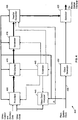
Transmitter 200 ofFIG. 2 is a more detailed diagram of one embodiment of theoptical transmitter 120 ofFIG. 1 .Transmitter 200, which receives the video signal fromdata source 110, is depicted as including a DVI/HDMI receiver 210, atransmitter circuit 220, asystem clock 230 and a transmitter electro-optical interface 240. While in one embodiment, thedata source 110 is an HDMI or DVI video source (e.g., ATSC tuner, DVD player, etc.), it may similarly be another type of data source. - As depicted in
FIG. 2 , thedata source 110 provides a digital signal to the DVI/HDMI receiver 210. The DVI/HDMI receiver 210 may be used to convert the DVI/HDMI digital signal from thedata source 110 into a digital video signal, such as 24-bit RGB. DVI/HDMI receivers are known in the field and beyond the scope of this disclosure. In another embodiment, the DVI/HDMI receiver 210 and thetransmitter circuit 220 may be combined into a single logical circuit. While in one embodiment, thetransmitter circuit 220 is a Field Programmable Gate Array (FPGA) or an Application-Specific Integrated Circuit (ASIC), it may similarly have other implementations. The other input for thetransmitter circuit 220 comes from thesystem clock 230, which provides a clock signal. In one embodiment, this clock signal is a 110 MHz signal. The output of thetransmitter circuit 220 is to a transmitter electro-optical interface 240. One embodiment of thetransmitter circuit 220 will be described in more detail below with reference toFIG. 4 , while one embodiment of the transmitter electro-optical interface 240 is described in more detail below with reference toFIG. 5 . -
Receiver 250 ofFIG. 3 is a more detailed diagram of one embodiment of theoptical receiver 140 ofFIG. 1 . In this embodiment,optical receiver 250, which receives theoptical signal 130 fromoptical transmitter 120, is depicted as including a receiver electro-optical interface 260, a receivingcircuit 270, a phase lock loop (PLL) 280, a DVI/HDMI transmitter 290, and asystem clock 300. Theoptical transmitter 250 is further depicted as outputting video data to displaydevice 150. While in one embodiment, the digital video data output to thedisplay device 150 is one of HDMI and DVI data, it may similarly be another type of data. - As depicted in
FIG. 3 , theoptical receiver 250 includes a DVI/HDMI transmitter 290, the details of which are known in the field and beyond the scope of this disclosure. In another embodiment, the DVI/HDMI transmitter 290 and thereceiver circuit 270 may be combined into a single logical circuit. As mentioned above, another input to thereceiver circuit 270 comes from thesystem clock 300, which provides a clock signal. In one embodiment, this clock signal is a 110 MHz signal. Thetransmitter circuit 270 is further depicted as being in communication withPLL 280, which may be used to help regenerate the video clock of the DVI/HDMI transmitter 290. - Referring now to
FIG. 4 , depicted is a block diagram of one embodiment of the transmitter circuit ofFIG. 2 . In this embodiment,transmitter circuit 400 includes afront end 405 which may be used to receive digital video data (such as 24-bit RGB) with control data from HDMI/DVI receiver 210, and optional ancillary data. Thefront end 405 may then output a near continuous stream of data to the optional RS (Reed-Solomon)Encoder 410. In one embodiment, this data is a 20-bit stream output at 110MHz. If the incoming video data rate is insufficient to satisfy theRS Encoder 410, null words may be generated such that theRS Encoder 410 is never starved for data. In one embodiment, theRS Encoder 410 may be comprised of two 10-bit encoders that apply an RS code of (216,200). TheRS Encoders 410 may each accept 200 10-bit words of data and add 16 words of forward error correction (FEC) data. This coding scheme enables the receiver to correct up to eight errors in each RS block of 216 words. In another embodiment, forward error correction may not be performed. - The RS Encoder may then output the data to the
scrambler 415, which randomizes the data. Thescrambler 415 may randomize the data to ensure that frequent transitions occur in the data stream. Frequent transitions help thereceiver 270 synchronize itself to the 2.2GHz bit clock and recover the data. In one embodiment, thescrambler 415 may use a pseudo-random number (PRN) generator to create a 20-bit random number for each 20-bit word. The incoming word is exclusive-OR'ed with the random number to produce a scrambled output. As will be described below, an identical PRN generator may be used on the receiver-side to unscramble the data. - The
header generator 420 may be used to output a word header. For example, in one embodiment, every 20uS theheader generator 420 may output a 40 word header. A first portion of this header (e.g., first 20 words) may be comprised of preset data used to synchronize the receiver, followed by a second portion (e.g., next 20 words) of variable data, which can include control information for the receiver-side. - The
serializer 425 receives the data stream from the header generator, according to one embodiment. Theserializer 425 is used to accept the encoded data in parallel and shift it out a bit at a time. In one embodiment, theserializer 425 outputs a high rate video data stream to the transmitter electro-optical interface 240. Theclock generator 430 synthesizes a clock (e.g., 2.2GHz) used by theserializer 425 for shifting the parallel data though the system based on the clock signal 435 (e.g., 110MHz) provided by a system clock (e.g., system clock 230). 2.2GHz may be used when electro-optical system 500 is tuned to operate at this specific bit rate. A 2.2 GHz bit rate may be used because it is exactly 20 times the 110 MHz clock rate. - Continuing to refer to
FIG. 4 , thecontroller 440 may be used to synchronize the various components of thetransmitter circuit 400. In one embodiment, it may inform theheader generator 420 when to generate a header. It may also initialize the PRN generator in thescrambler 415. Moreover, thecontroller 440 may also start theRS Encoder 410 such that its output will be present at the proper time. In one embodiment, thecontroller 440 may also inform thefront end 405 when data must be available to theRS Encoder 410. In the embodiment ofFIG. 4 , thecontroller 440 outputs a clock to the video clock analyzer (VCA) 445. TheVCA 445 may be used to count the number of video clocks per time interval, with the resulting count "n" being transmitted to the receiver-side as part of the header's variable data. In one embodiment, "n" may be used on the receiver-side to regenerate the video clock. - Referring now to
FIG. 5 , depicted is a block diagram of one embodiment of an electro-optical system 500, which includes the transmitting electro-optical interface 240 ofFIG. 2 communicating with the receiving electro-optical interface 260 ofFIG. 3 . In this embodiment, the transmitting electro-optical interface 240 provides anoptical signal 550 which is received by the receiving electro-optical interface 260. In this embodiment, the transmittingcircuit 220 provides the video signal in the form of a digital electrical signal to thelaser driver 510 which, in turn, generates a series of electrical potentials to thelaser diode 520. This sequence of electrical potentials is used by thelaser diode 520 to convert the signal into anoptical signal 550. Moreover, acollimating lens 530 may be used to focus theoptical signal 550 such that it is properly receivable by the receiving electro-optical interface 260. - A focusing
lens 540 may be used to capture and focus theoptical signal 550 onto aphoto diode 560. Thephoto diode 560 receives and converts theoptical signal 550 into a digital electrical signal which may then be passed to a trans-impedance amp 570 and then to a limitingamp 580. - Referring now to
FIG. 6 , depicted is a block diagram of a particular embodiment of thereceiver circuit 270 ofFIG. 3 . In particular, data is received by thereceiver circuit 600 into a clock/data recovery block 610 from the receiver electo-optical interface 260. In one embodiment, the function of the clock/data recovery block 610 is to extract the original transmit clock (e.g., 2.2GHz) and divide it down to reproduce the transmitter's system clock 230 (e.g., 110MHz) for use in moving the data through thereceiver circuit 600. Moreover, clock/data recovery block 610 may also deserialize the data to determine where one word ends and the next begins within the serial data stream. - The
header detector 620 may be used to search for the headers previously inserted by the transmitter circuit'sheader generator 420. When the header is found, theheader detector 620 may signal thecontroller 630 to synchronize itself with the data stream. Once synchronized, thecontroller 630 may synchronize the other processing blocks in thereceiver circuit 600. - The remaining processing blocks in the
receiver circuit 600 are complementary to those in thetransmitter circuit 400 ofFIG. 4 . For example, thedescrambler 640 may contain a PRN generator that is initialized by thecontroller 630 at the proper time such that the data following the header is restored to its pre-scrambled values. TheRS Decoder 650 is used to decode the data, followed by final processing and demultiplexing by a back-end 660, which is complimentary to the previously-describedfront end 405. In one embodiment, thebackend 660 is responsible for taking the data stream and extracting the original video and control data. - As previously mentioned, one aspect of the invention is to provide the video data to the
display 150 at the same resolution and with the same video clock speed as that of thevideo source 110. For example, HDMI and DVI provide a mechanism for thevideo source 110 to query the video display 150 (sink) as to what video formats are supported. Once queried, thevideo source 110 may select the "best" video format for sending video data to thedisplay 150. As will be described in more detail below, this query communication may be performed over an I2C link. - With that said, the electro-
optical system 500 has no way of knowing what video format will be selected by thevideo source 110. For this reason, the electro-optical system 500 will be able to accommodate any arbitrary clock rate, according to one embodiment. - While it may be possible to first convert the incoming video data to a standard format having a predetermined video clock rate, such an additional conversion operation is undesirable due to the processing overhead and image distortion inherent in such a conversion process. Moreover, such a system would not be able to pass HDMI data due in part to the fact that the video conversion process necessarily modifies the video clock which would be needed by the display to extract data-islands in which audio information is embedded. In addition, such a system would not support the HDCP scheme. If the video data is encrypted, the display will not be able to decrypt the data without the original video clock.
- Thus, in one embodiment, the video data is transmitted from the
video source 110 through the electro-optical system 500 and to thedisplay 150 in what ever format and with the appropriate video clock, as determined by thesource 110. In one embodiment, this is accomplished by regenerating the video clock in thereceiver 140. The flow of video data through the system is isochronous and the regenerated video clock must be phase-locked to the source's video clock. Video clock regeneration may be accomplished using a video clock counter in the transmitter (e.g., video clock analyzer 445) and a special PLL (e.g., PLL 280) in the receiver coupled to thevideo clock generator 680. At both the receiver and transmitter end, the same 110 MHz clock signal is used as a reference. This 110 MHz clock signal originates at the transmitter and is indirectly used to clock data across the wireless optical link. In the transmitter, thecontroller 440 divides the 110 MHz clock down to create a 50 kHz clock. This 50 kHz clock may then be used as a reference for thevideo clock analyzer 445. In the receiver, thecontroller 630 divides the 110MHz clock down to create a 50kHz clock. This 50kHz clock is used as a reference forvideo clock generator 680. The video clock generator uses the 50kHz reference clock and the "n" value to regenerate the original video clock. - As previously mentioned, one aspect of the invention is to use a control channel communication system to enable content (e.g., DVI and HDMI content) to be transmitted wirelessly. In one embodiment, this control -channel communication system is provided by a low data-rate 2.4GHz RF link. Other embodiments may implement some of the control-channel functionality in the optical link.
- In another embodiment, the RF link is used to perform required I2C queries of the display. I2C is an interface used to control components in consumer electronics. One application of I2C is HDCP (High-bandwidth Digital Content Protection) to exchange keys and other information over a DVI/HDMI cable between a source (i.e. DVD player) and a sink (i.e. display). I2C is a memory-bus-like protocol used over two wires to control components in consumer electronic systems. A master, such as a microcontroller, can write commands and read status from register locations in one or more slave devices. Buffering devices permit wired extensions but the memory bus nature of the protocol make real-time wireless extension difficult. Converting the connection to wireless requires preserving real time response with minimal data transfer latency.
- Referring now to
FIG. 7 , depicted is one embodiment of how a control-channel communication system 700 may be implemented. In this embodiment, amaster 710 communicates wirelessly throughslave simulator 720, while aslave device 750 communicates wirelessly throughmaster simulator 740. In one embodiment, the master is thetransmitter 120, while theslave 750 is thereceiver 140. Moreover, the components which comprise theslave simulator 720 and themaster simulator 740 may be integrated, in whole or in part, with thetransmitter 120 andreceiver 140, respectively. Moreover, while in oneembodiment wireless link 730 is a 2.4GHz RF link, it should similarly be appreciated that it may be any other type of wireless link. - With writes from the
master 710 to theslave 750, address and data information are simply relayed with a minimum of overhead. This involves capturing the writes with appropriate handshakes, wrapping the content into the wireless protocol, and reconstituting the write operation on the receiving side. In one embodiment, this may be implemented as a "store and forward" operation starting with theslave simulator 720 receiving the command, then passing it over the link to themaster simulator 740, which in turn sends it onto theslave 750. A few milliseconds end-to-end delay may be introduced, but all protocol timing is met. - I2C reads expect immediate response. There is not sufficient time to send the read command over the link followed by return of the desired data. Thus, in one embodiment, a shadow memory may be used on each side. These memories may mirror what is found in the slave device registers. The slave side of the link may poll the device registers and maintain a local shadow copy. When a change of data is noted, updates may be sent over the
link 730 to the master side shadow. This data may then be available to themaster 710 on demand. In this manner, all I2C protocol timing is maintained and themaster 710 has no idea it is not accessing the real device. - In another embodiment, shadow memory in the
slave simulator 720 may be implemented as a dual port RAM and kept current by themaster simulator 740. Any changes in the actual device data may be noted by themaster simulator 740 with updates sent to theslave simulator 720. - As previously mentioned, a second shadow memory may be maintained in the
master simulator 740 attached to theactual slave device 750. It may be used to store the reference values for determining when slave data has changed. Themaster simulator 740 may keep both memories current by polling theslave 750 through, for example, all possible sub-addresses or, alternatively, only touching the ones known to be volatile. - While the invention has been described in connection with various embodiments, it will be understood that the invention is capable of further modifications. This application is intended to cover any variations, uses or adaptation of the invention following, in general, the principles of the invention, and including such departures from the present disclosure as come within the known and customary practice within the art to which the invention pertains.
Claims (25)
- A system comprising:a video data source (110) having a source output;an optical wireless transmitter (120) adapted to receive video data from the source output and encode said video data into a laser beam and a scrambler (415) operable to receive the video data and to scramble the video data so as to randomize the video data to be encoded onto the laser beam;an optical wireless receiver (140) adapted to receive said laser beam and to extract said scrambled video data there from and a descrambler (640) operable to receive the scrambled video data and to descramble the scrambled video data to output the video data; anda display device (150) having a destination input, wherein said display device is adapted to receive said video data from said optical wireless receiver and to present a video display based on said video data.
- The system of claim 1, wherein said video data has a video format determined by said video data source (110), and wherein said optical wireless transmitter (120) is to provide said video data to said optical wireless receiver (140) in said determined video format.
- The system of claim 1, wherein said optical wireless transmitter (120) includes a laser diode (520) and a collimating lens (530), and wherein said laser beam is generated using said laser diode (520) and then directed using said collimating lens (530).
- The system of claim 1, wherein said optical wireless receiver (140) includes a focusing lens (540) and a photo diode (560) usable to receive said laser beam.
- The system of claim 1, wherein said video data is encrypted using High-Bandwidth Digital-Content Protection.
- The system of claim 1, wherein said video data is transmitted from said optical wireless transmitter (120) to said optical wireless receiver (140) at a rate of approximately 2.2 Gbps.
- The system of claim 1, wherein said optical wireless receiver (140) is further to recover a video clock signal from said video data, wherein said video clock signal is generated by the optical wireless transmitter (120) and encoded into said video data.
- The system of claim 1, wherein said video data has forward error correction encoding applied to correct errors caused by sending said video data from said optical wireless transmitter (120) to said optical wireless receiver (140).
- The system of claim 1, wherein said source output is one of a Digital Visual Interface (DVI), High Definition Multimedia Interface (HDMI), and High Definition Serial Digital Interface (HD SDI) output.
- The system of claim 1, further comprising a control-channel radio frequency communication link to enable said video data source (110) to exchange information with said display device (150).
- The system of claim 10, wherein said video data is encrypted using High-Bandwidth Digital-Content Protection.
- The system of claim 10, wherein said video data source (110) and display device (150) exchange information over said control-channel radio frequency communication link to satisfy one or more DVI or HDMI queries.
- A method comprising:receiving video data from a source output and scrambling the video data so that the video data is randomized;encoding said video data into a laser beam;transmitting said laser beam from an optical wireless transmitter (120) to an optical wireless receiver (140);receiving said laser beam by the optical wireless receiver (140) to extract said scrambled video data there from and to descramble the scrambled video data; andproviding said descrambled video data to a display device (150) having a destination input.
- The method of claim 13, wherein said video data has a video format determined by said source output, and wherein said transmitting said laser beam comprises transmitting said video data encoded into said laser beam in said determined video format.
- The method of claim 13, wherein transmitting said laser beam comprises transmitting said laser beam using a laser diode (520) and a collimating lens (530) of the optical wireless transmitter (120).
- The method of claim 15, further comprising generating said laser beam using said laser diode (520), and directing said laser beam to said optical wireless receiver (140) using said collimating lens (530).
- The method of claim 13, wherein transmitting said laser beam comprises transmitting said laser beam from the optical wireless transmitter (120) to the optical wireless receiver (140), wherein said optical wireless receiver (140) includes a focusing lens (540) and a photo diode (560) usable to receive said laser beam.
- The method of claim 13, wherein transmitting said laser beam comprises transmitting said laser beam from said optical wireless transmitter (120) to said optical wireless receiver (140) at a rate of approximately 2.2 Gbps.
- The method of claim 13, further comprising:measuring a video clock signal by the optical wireless transmitter (120) to provide a video clock measurement; andencoding said video clock measurement into said video data.
- The method of claim 19, further comprising recovering said video clock signal from said video data using said optical wireless receiver (140).
- The method of claim 13, wherein said source output is one of a Digital Visual Interface (DVI), High Definition Multimedia Interface (HDMI), and High Definition Serial Digital Interface (HD SDI) output.
- The method of claim 13, further comprising exchanging information over a control-channel radio frequency communication link between said source output and said display device (150).
- The method of claim 22, wherein said video data is encrypted using High-Bandwidth Digital-Content Protection.
- The method of claim 22, wherein said source output and display device (150) exchange information over said control-channel radio frequency communication link to satisfy one or more DVI or HDMI queries.
- The method of claim 13, further comprising applying forward error correction to said video data to correct errors caused by said transmitting said laser beam from the optical wireless transmitter (120) to the optical wireless receiver (140).
Applications Claiming Priority (2)
| Application Number | Priority Date | Filing Date | Title |
|---|---|---|---|
| US11/036,479 US7675509B2 (en) | 2005-01-13 | 2005-01-13 | Methods and apparatus for optical wireless communication |
| PCT/US2005/043917 WO2006076091A2 (en) | 2005-01-13 | 2005-12-05 | Methods and apparatus for optical wireless communication |
Publications (3)
| Publication Number | Publication Date |
|---|---|
| EP1836783A2 EP1836783A2 (en) | 2007-09-26 |
| EP1836783A4 EP1836783A4 (en) | 2013-12-18 |
| EP1836783B1 true EP1836783B1 (en) | 2018-10-10 |
Family
ID=36653361
Family Applications (1)
| Application Number | Title | Priority Date | Filing Date |
|---|---|---|---|
| EP05852973.6A Active EP1836783B1 (en) | 2005-01-13 | 2005-12-05 | Methods and apparatus for optical wireless communication |
Country Status (7)
| Country | Link |
|---|---|
| US (2) | US7675509B2 (en) |
| EP (1) | EP1836783B1 (en) |
| JP (1) | JP4794574B2 (en) |
| KR (1) | KR101211891B1 (en) |
| CN (1) | CN101099316B (en) |
| CA (1) | CA2592734C (en) |
| WO (1) | WO2006076091A2 (en) |
Families Citing this family (24)
| Publication number | Priority date | Publication date | Assignee | Title |
|---|---|---|---|---|
| US8560753B1 (en) * | 2005-03-30 | 2013-10-15 | Teradici Corporation | Method and apparatus for remote input/output in a computer system |
| KR100748468B1 (en) * | 2006-01-02 | 2007-08-10 | 삼성전자주식회사 | System and Method for retransmitting contents using IrDA communication |
| KR100725945B1 (en) * | 2006-01-03 | 2007-06-11 | 삼성전자주식회사 | Broadcasting signal retransmitting system and method using illuminated light communication |
| DE102006015393A1 (en) * | 2006-04-03 | 2007-10-04 | Rohde & Schwarz Gmbh & Co. Kg | Digital audio/video data stream`s transmission time synchronizing arrangement, has transmitters provided with data stream in form of data frame, where reference time is compared with actual transmission time for each transmitter |
| US7577898B2 (en) * | 2006-04-10 | 2009-08-18 | At&T Intellectual Property I, L.P. | System and method of correcting video data errors |
| DE102006035862B4 (en) * | 2006-08-01 | 2010-04-15 | Siemens Ag | Device and adapter system for transmitting monochrome image information |
| US8315332B2 (en) * | 2009-03-06 | 2012-11-20 | Sony Corporation | System and method for transmitting data using quantized channel rates |
| US20110088056A1 (en) * | 2009-10-12 | 2011-04-14 | At&T Intellectual Property I, L.P. | Portable wireless accessory for a wireless communication system |
| CN102893602B (en) | 2010-02-22 | 2016-08-10 | 杜比实验室特许公司 | Have and use the video presenting control embedding metadata in the bitstream to show |
| US9842564B2 (en) | 2010-10-28 | 2017-12-12 | Samsung Electronics Co., Ltd. | Method and system for wireless video transmission via different interfaces |
| US20120182473A1 (en) * | 2011-01-14 | 2012-07-19 | Gyudong Kim | Mechanism for clock recovery for streaming content being communicated over a packetized communication network |
| US8866870B1 (en) * | 2011-10-20 | 2014-10-21 | Lockheed Martin Corporation | Methods, apparatus, and systems for controlling from a first location a laser at a second location |
| KR101503521B1 (en) * | 2012-01-18 | 2015-03-19 | 경희대학교 산학협력단 | Receiver, transmitter and optical wireless communication system |
| WO2013149021A1 (en) * | 2012-03-28 | 2013-10-03 | Huawei Technologies Co., Ltd. | Transmitter noise injection |
| US9262988B2 (en) * | 2013-08-02 | 2016-02-16 | Lattice Semiconductor Corporation | Radio frequency interference reduction in multimedia interfaces |
| CN104639919B (en) * | 2013-11-14 | 2017-11-03 | 杭州海康威视数字技术股份有限公司 | Data transmission method and its system for digital video fiber optic transmitter system |
| US10133611B2 (en) * | 2014-10-07 | 2018-11-20 | Synopsys, Inc. | Side channel communication hardware driver |
| KR101933511B1 (en) | 2016-06-20 | 2019-04-03 | 주식회사 하우앳 | Wireless optic transceiver device |
| CN109391839B (en) * | 2017-08-10 | 2021-03-09 | 北京正唐科技有限责任公司 | Self-adaptive HDMI (high-definition multimedia interface) video transmission device |
| KR102471492B1 (en) * | 2017-12-27 | 2022-11-28 | 삼성전자 주식회사 | Display apparatus and control method thereof |
| US10983344B2 (en) | 2018-08-10 | 2021-04-20 | 8 Rivers Capital, Llc. | System for optical wireless communication to extended reality immersion device |
| CN109151344A (en) * | 2018-09-26 | 2019-01-04 | 深圳蓝集科技有限公司 | A kind of automatic redundant transmission device of wireless image transmission |
| CN112153209B (en) * | 2019-06-28 | 2022-05-20 | Oppo广东移动通信有限公司 | Communication system and method of mobile terminal, computer and mobile terminal |
| US20230089347A1 (en) * | 2021-09-17 | 2023-03-23 | Vertiv It Systems, Inc. | Systems and methods for a secured communication between computers and peripheral devices |
Citations (1)
| Publication number | Priority date | Publication date | Assignee | Title |
|---|---|---|---|---|
| EP0866581A2 (en) * | 1997-03-17 | 1998-09-23 | AT&T Corp. | Methods and apparatus for secure optical communications links |
Family Cites Families (22)
| Publication number | Priority date | Publication date | Assignee | Title |
|---|---|---|---|---|
| USH247H (en) * | 1986-07-11 | 1987-04-07 | The United States Of America As Represented By The Secretary Of The Army | Roll measurement system for flight vehicle |
| US5613135A (en) * | 1992-09-17 | 1997-03-18 | Kabushiki Kaisha Toshiba | Portable computer having dedicated register group and peripheral controller bus between system bus and peripheral controller |
| JPH06103188A (en) * | 1992-09-17 | 1994-04-15 | Toshiba Corp | Personal computer |
| US6348986B1 (en) * | 1996-03-29 | 2002-02-19 | Dominion Lasercom. Inc. | Wireless fiber-coupled telecommunication systems based on atmospheric transmission of laser signals |
| US6128433A (en) * | 1997-12-31 | 2000-10-03 | Indigita Corporation | Controlling frequency drift of a digital video tape drive |
| JP2000022632A (en) * | 1998-06-26 | 2000-01-21 | Sony Corp | Image display device |
| AUPP990199A0 (en) * | 1999-04-22 | 1999-05-13 | Griffith University | Wireless video surveillance system |
| CA2273657C (en) * | 1999-05-05 | 2010-09-21 | Nortel Networks Corporation | Telephony and data network services at a telephone |
| US7012576B2 (en) * | 1999-12-29 | 2006-03-14 | Intel Corporation | Intelligent display interface |
| GB0025463D0 (en) * | 2000-10-17 | 2000-11-29 | Isis Innovation | Improvements in or relating to optical wireless communications |
| KR20030085094A (en) * | 2001-04-03 | 2003-11-01 | 미쓰비시덴키 가부시키가이샤 | Encrypting device |
| CN1873769B (en) * | 2002-02-19 | 2010-06-09 | 株式会社东芝 | Data display system, data relay device, data relay method, and data system |
| US20030220781A1 (en) * | 2002-02-25 | 2003-11-27 | Oak Technology, Inc. | Communication architecture utilizing emulator interface |
| JP4202673B2 (en) * | 2002-04-26 | 2008-12-24 | 株式会社東芝 | System LSI development environment generation method and program thereof |
| US7283566B2 (en) * | 2002-06-14 | 2007-10-16 | Silicon Image, Inc. | Method and circuit for generating time stamp data from an embedded-clock audio data stream and a video clock |
| US20040110468A1 (en) * | 2002-12-10 | 2004-06-10 | Perlman Stephen G. | Wireless network with presentation and media layers for broadcast satellite and cable services |
| JP2004260817A (en) * | 2003-02-27 | 2004-09-16 | Amtran Technology Co Ltd | Radio signal transceiver system |
| US7016406B1 (en) * | 2003-04-29 | 2006-03-21 | Scintera Networks | Adaptation structure and methods for analog continuous time equalizers |
| US7965837B2 (en) * | 2003-04-30 | 2011-06-21 | Sony Corporation | Method and system for wireless digital video presentation |
| AU2003299922A1 (en) * | 2003-06-02 | 2005-01-04 | Paul Tzeng | Optical transmitting and receiving system |
| KR100586669B1 (en) * | 2003-08-27 | 2006-06-08 | 닛뽕빅터 가부시키가이샤 | Transmission system |
| US7634090B2 (en) * | 2003-09-26 | 2009-12-15 | Genesis Microchip Inc. | Packet based high definition high-bandwidth digital content protection |
-
2005
- 2005-01-13 US US11/036,479 patent/US7675509B2/en not_active Expired - Fee Related
- 2005-12-05 CN CN2005800463731A patent/CN101099316B/en not_active Expired - Fee Related
- 2005-12-05 WO PCT/US2005/043917 patent/WO2006076091A2/en active Application Filing
- 2005-12-05 EP EP05852973.6A patent/EP1836783B1/en active Active
- 2005-12-05 KR KR1020077018058A patent/KR101211891B1/en active IP Right Grant
- 2005-12-05 JP JP2007551257A patent/JP4794574B2/en not_active Expired - Fee Related
- 2005-12-05 CA CA2592734A patent/CA2592734C/en active Active
-
2010
- 2010-01-20 US US12/690,836 patent/US8514208B2/en active Active
Patent Citations (1)
| Publication number | Priority date | Publication date | Assignee | Title |
|---|---|---|---|---|
| EP0866581A2 (en) * | 1997-03-17 | 1998-09-23 | AT&T Corp. | Methods and apparatus for secure optical communications links |
Also Published As
| Publication number | Publication date |
|---|---|
| US20060153572A1 (en) | 2006-07-13 |
| WO2006076091A3 (en) | 2006-11-02 |
| JP4794574B2 (en) | 2011-10-19 |
| KR20070093449A (en) | 2007-09-18 |
| EP1836783A2 (en) | 2007-09-26 |
| JP2008527914A (en) | 2008-07-24 |
| CN101099316A (en) | 2008-01-02 |
| KR101211891B1 (en) | 2012-12-13 |
| EP1836783A4 (en) | 2013-12-18 |
| CA2592734A1 (en) | 2006-07-20 |
| US20110064413A1 (en) | 2011-03-17 |
| WO2006076091A2 (en) | 2006-07-20 |
| CA2592734C (en) | 2014-09-23 |
| US7675509B2 (en) | 2010-03-09 |
| US8514208B2 (en) | 2013-08-20 |
| CN101099316B (en) | 2011-08-10 |
Similar Documents
| Publication | Publication Date | Title |
|---|---|---|
| EP1836783B1 (en) | Methods and apparatus for optical wireless communication | |
| JP4891913B2 (en) | Data transmission system, transmission digital processing system, reception digital processing system | |
| US9456236B2 (en) | Systems, devices and methods for reducing switching time in a video distribution network | |
| KR101412297B1 (en) | Content-Projected Digital Link Over A Single Signal Lime | |
| US9516362B2 (en) | Devices, systems and methods for reducing switching time in a video distribution network | |
| EP2122961B1 (en) | Robust control/delineation in serial streams | |
| US8589770B2 (en) | Robust control/delineation in serial streams | |
| KR20080066506A (en) | Apparatus and method for receiving digital contents | |
| JP6171065B2 (en) | Display device and display method | |
| KR20040042001A (en) | Video transmitter for protecting DVI outputs and method thereof | |
| JP6039707B2 (en) | Video signal processing apparatus and method | |
| JP7352611B2 (en) | Video signal processing device | |
| JP7307513B2 (en) | Display device | |
| JP6286082B2 (en) | Display device | |
| JP6249311B2 (en) | Output device | |
| JP2018121339A (en) | Display device |
Legal Events
| Date | Code | Title | Description |
|---|---|---|---|
| PUAI | Public reference made under article 153(3) epc to a published international application that has entered the european phase |
Free format text: ORIGINAL CODE: 0009012 |
|
| 17P | Request for examination filed |
Effective date: 20070727 |
|
| AK | Designated contracting states |
Kind code of ref document: A2 Designated state(s): DE FR GB |
|
| RBV | Designated contracting states (corrected) |
Designated state(s): DE FR GB |
|
| RBV | Designated contracting states (corrected) |
Designated state(s): DE FR GB |
|
| DAX | Request for extension of the european patent (deleted) | ||
| RBV | Designated contracting states (corrected) |
Designated state(s): DE FR GB |
|
| A4 | Supplementary search report drawn up and despatched |
Effective date: 20131114 |
|
| RIC1 | Information provided on ipc code assigned before grant |
Ipc: H04B 10/114 20130101AFI20131108BHEP |
|
| STAA | Information on the status of an ep patent application or granted ep patent |
Free format text: STATUS: EXAMINATION IS IN PROGRESS |
|
| 17Q | First examination report despatched |
Effective date: 20171016 |
|
| REG | Reference to a national code |
Ref country code: DE Ref legal event code: R079 Ref document number: 602005054781 Country of ref document: DE Free format text: PREVIOUS MAIN CLASS: H04B0010000000 Ipc: H04B0010114000 |
|
| RIC1 | Information provided on ipc code assigned before grant |
Ipc: H04N 21/41 20110101ALI20180307BHEP Ipc: H04N 7/16 20110101ALI20180307BHEP Ipc: H04B 10/114 20130101AFI20180307BHEP Ipc: H04N 21/4367 20110101ALI20180307BHEP Ipc: H04N 7/22 20060101ALI20180307BHEP |
|
| GRAP | Despatch of communication of intention to grant a patent |
Free format text: ORIGINAL CODE: EPIDOSNIGR1 |
|
| STAA | Information on the status of an ep patent application or granted ep patent |
Free format text: STATUS: GRANT OF PATENT IS INTENDED |
|
| INTG | Intention to grant announced |
Effective date: 20180502 |
|
| GRAS | Grant fee paid |
Free format text: ORIGINAL CODE: EPIDOSNIGR3 |
|
| GRAA | (expected) grant |
Free format text: ORIGINAL CODE: 0009210 |
|
| STAA | Information on the status of an ep patent application or granted ep patent |
Free format text: STATUS: THE PATENT HAS BEEN GRANTED |
|
| AK | Designated contracting states |
Kind code of ref document: B1 Designated state(s): DE FR GB |
|
| REG | Reference to a national code |
Ref country code: GB Ref legal event code: FG4D |
|
| REG | Reference to a national code |
Ref country code: DE Ref legal event code: R096 Ref document number: 602005054781 Country of ref document: DE |
|
| REG | Reference to a national code |
Ref country code: DE Ref legal event code: R097 Ref document number: 602005054781 Country of ref document: DE |
|
| PLBE | No opposition filed within time limit |
Free format text: ORIGINAL CODE: 0009261 |
|
| STAA | Information on the status of an ep patent application or granted ep patent |
Free format text: STATUS: NO OPPOSITION FILED WITHIN TIME LIMIT |
|
| 26N | No opposition filed |
Effective date: 20190711 |
|
| PGFP | Annual fee paid to national office [announced via postgrant information from national office to epo] |
Ref country code: DE Payment date: 20201229 Year of fee payment: 16 |
|
| REG | Reference to a national code |
Ref country code: DE Ref legal event code: R119 Ref document number: 602005054781 Country of ref document: DE |
|
| PG25 | Lapsed in a contracting state [announced via postgrant information from national office to epo] |
Ref country code: DE Free format text: LAPSE BECAUSE OF NON-PAYMENT OF DUE FEES Effective date: 20220701 |
|
| P01 | Opt-out of the competence of the unified patent court (upc) registered |
Effective date: 20230606 |
|
| PGFP | Annual fee paid to national office [announced via postgrant information from national office to epo] |
Ref country code: GB Payment date: 20231121 Year of fee payment: 19 |
|
| PGFP | Annual fee paid to national office [announced via postgrant information from national office to epo] |
Ref country code: FR Payment date: 20231122 Year of fee payment: 19 |