EP1835727B1 - Color correction method, color correction device, and color correction program - Google Patents
Color correction method, color correction device, and color correction program Download PDFInfo
- Publication number
- EP1835727B1 EP1835727B1 EP06116633A EP06116633A EP1835727B1 EP 1835727 B1 EP1835727 B1 EP 1835727B1 EP 06116633 A EP06116633 A EP 06116633A EP 06116633 A EP06116633 A EP 06116633A EP 1835727 B1 EP1835727 B1 EP 1835727B1
- Authority
- EP
- European Patent Office
- Prior art keywords
- color
- color signals
- values
- display signal
- signal space
- Prior art date
- Legal status (The legal status is an assumption and is not a legal conclusion. Google has not performed a legal analysis and makes no representation as to the accuracy of the status listed.)
- Active
Links
- 238000000034 method Methods 0.000 title claims description 19
- 238000006243 chemical reaction Methods 0.000 claims description 30
- 239000011159 matrix material Substances 0.000 claims description 27
- 230000000694 effects Effects 0.000 description 4
- 239000003086 colorant Substances 0.000 description 3
- 230000001413 cellular effect Effects 0.000 description 1
- 230000004069 differentiation Effects 0.000 description 1
- 230000036074 healthy skin Effects 0.000 description 1
- 239000000203 mixture Substances 0.000 description 1
- 230000004044 response Effects 0.000 description 1
Images


Classifications
-
- H—ELECTRICITY
- H04—ELECTRIC COMMUNICATION TECHNIQUE
- H04N—PICTORIAL COMMUNICATION, e.g. TELEVISION
- H04N1/00—Scanning, transmission or reproduction of documents or the like, e.g. facsimile transmission; Details thereof
- H04N1/46—Colour picture communication systems
- H04N1/56—Processing of colour picture signals
- H04N1/60—Colour correction or control
- H04N1/6002—Corrections within particular colour systems
- H04N1/6005—Corrections within particular colour systems with luminance or chrominance signals, e.g. LC1C2, HSL or YUV
-
- H—ELECTRICITY
- H04—ELECTRIC COMMUNICATION TECHNIQUE
- H04N—PICTORIAL COMMUNICATION, e.g. TELEVISION
- H04N1/00—Scanning, transmission or reproduction of documents or the like, e.g. facsimile transmission; Details thereof
- H04N1/46—Colour picture communication systems
- H04N1/56—Processing of colour picture signals
- H04N1/60—Colour correction or control
- H04N1/6002—Corrections within particular colour systems
- H04N1/6008—Corrections within particular colour systems with primary colour signals, e.g. RGB or CMY(K)
Definitions
- the present invention relates to a color correction method, a color correction device, and a color correction program for conducting color correction with respect to image signals by referring to a LUT. More particularly, the present invention relates to a color correction method and the like capable of reducing the color spacing of a LUT, while avoiding capacity increase of the memory that stores the LUT.
- a technology has been known by which, for example, a color of an image is beautifully displayed by conducting color correction with respect to TV video signals or image signals of digital cameras.
- a method for conducting color correction by using matrix computations for example, see Japanese Patent No. 3611490 , in particular Fig. 5 or Formula (1)
- a method for adjusting the lightness, saturation, and hue based on the maximum value, central value, and minimum value of the RGB signal for example, see Japanese Patent Application Laid-Open No. 2003-163814 , in particular Fig. 6 have been disclosed as the conventional technology of this type.
- color correction is also conducted by using three-dimensional color tables.
- Color correction based on three-dimensional color tables was indicated to have high color reproducibility (for example, see the section relating to prior art in Japanese Patent No. 3611490 ), and the advantages of such color correction include good quality of displayed image and the capability of independently adjusting different colors.
- a three-dimensional color table stores the adjustment values of each component of an image signal (YUV, YCC, YCbCr, L*a*b, etc.) of a luminance - color difference system, but the values are stored discretely with consideration for memory capacity.
- the corrected image signal is then generated by conducting interpolation computations from the discrete values.
- the procedure described in Japanese Patent No. 3664364 is known as an interpolation computation procedure.
- the color table has to be configured with a spacing that is fine enough to maintain the image quality.
- the increase in memory capacity is also required to be prevented.
- US 2002/0060797 A1 shows an apparatus for converting a color gamut of an input color image, comprising a three-dimensional (3-D) difference lookup table for storing differences between input values corresponding to upper n bits of the input color image and 3-D converted color data thereof, a color interpolator for performing 3-D interpolation using 3-D converted data, which are output from the 3-D lookup difference lookup table, and 3-D color data corresponding to lower m bits of the input color image, and an adder for receiving output of the color interpolator and the input color image, and outputting an image whose colors have been finally converted.
- 3-D three-dimensional
- a system and method for converting a color represented in a first color space to the color represented in a second color space uses a constant hue algorithm.
- the constant hue algorithm is used to compensate invalid colors in the second color space obtained as a result of the conversion.
- the constant hue algorithm determines a compensation factor that, in effect, blends the invalid color with pure grey until the invalid color becomes a valid color in the second color space.
- the compensation factor is optionally stored with the valid color in the second color space so that the original color in the first color space can be subsequently recovered.
- the present invention was created to resolve the above-described problems and it is an object thereof to provide a color correction method, a color correction device, and a color correction program that can realize color correction processing with a fine-spacing color table, while preventing the increase in memory capacity.
- the present invention provides a color correction method, and a color correction program as defined in the claims.
- the present invention provides a color correction method, a color correction device, and a color correction program that can realize color correction processing with a color table with a fine spacing, while preventing the increase in memory capacity.
- Fig. 1A shows a configuration example of a color correction device 1.
- the color correction device 1 has a matrix conversion unit 10, a RGB color adjustment LUT (Look Up Table) 20, and an interpolation computation unit 30.
- the matrix conversion unit 10 converts the inputted image signal of a luminance - color difference system into an image signal of a display signal system, which is a signal system of a display unit.
- the image signal of the luminance - color difference system is taken as a YCC (luminance signal (Y) and two color difference signals (C)), and the image signal of the display signal system is taken as a RGB (Red, Green, Blue) signal.
- YCC luminance signal
- C color difference signals
- RGB Red, Green, Blue
- Gradation values after the adjustment relating to the RGB signal are stored in the RGB color adjustment LUT 20.
- An example of the gradation values stored in the LUT 20 is shown in Fig. 2A .
- the values stored in the RGB color adjustment LUT 20 are values of RGB (three-dimensional) after color adjustment. For example, each value is stored so as to be available in response to a request, for example, when the displayed image has to be adjusted to a healthy skin color. The adjustment value that is wished to be adjusted may be registered for each RGB in advance.
- the RGB color adjustment LUT 20 stores discrete values with consideration for memory capacity.
- the interpolation computation unit 30 conducts interpolation computation from each adjusted value that was read out from the RGB color adjustment LUT 20.
- the RGB signal after interpolation computation is output to display unit as a RGB signal after correction.
- Fig. 1B shows another configuration example of the color correction device 1.
- the color correction device 1 has different configuration of the matrix conversion unit 11 and additionally has an excess amount compensation unit 40.
- the RGB color adjustment LUT 20 and interpolation computation unit 30 are identical to those of the color correction device 1 shown in Fig. 1A .
- Fig. 3A shows a configuration example of the matrix conversion unit 11.
- the matrix conversion unit 11 has a gradation correction unit 110, a matrix processing unit 111, and a clip processing unit 112.
- the gradation correction unit 110 conducts correction computation with respect to the YCC signal. With such correction computation, a bright color can be reproduced and lightness can be somewhat improved. Specific processing conducted in the gradation correction unit 110 will be described below.
- the matrix processing unit 111 has a configuration identical to that of the matrix conversion unit 10 shown in Fig. 1A and conducts identical processing.
- the YCC signal after the correction is inputted and converted into the RGB signal of the display system by conducting matrix computation.
- the clip processing unit 112 conducts clip processing with respect to the converted RGB signal.
- the clip processing is a process in which, when overflow or underflow has occurred with respect to each gradation value of the RGB signal, the overflow value or the underflow value is deducted to inhibit overflow, etc., by conducting correction computation in the gradation correction unit 110 (or computation by matrix conversion in the matrix processing unit 111).
- the value corresponding to the overflow, etc. is outputted as a color region excess amount from the clip processing unit 112 to the excess amount compensation unit 40.
- the excess amount compensation unit 40 inputs the color-adjusted RGB signal after interpolation computation and the color region excess amount and conducts the processing of adding the color region excess amount to the color-adjusted RGB signal.
- the excess amount compensation unit 40 outputs the RGB signal after the addition to the display unit as a RGB signal subjected to color region excess compensation and correction.
- the color region excess fraction is compressed by the matrix conversion unit 11 (clip processing unit 112) and compensation of this color region excess fraction is conducted with the excess amount compensation unit 40.
- Fig. 3B shows a configuration example of the other color correction device 1.
- this device has a RGB color adjustment differential LUT 21 as a LUT for color adjustment with respect to the RGB signal and additionally has an addition unit 50.
- Fig. 2B shows an example of values stored in the RGB color adjustment differential LUT 21.
- the processing results relating to each color of RGB were stored (see Fig. 2A ), whereas in the RGB color adjustment differential LUT 21, the differential values are stored.
- the compensation computation is conducted with respect to the differential values and a color-adjusted differential RGB signal is outputted.
- the addition unit 50 adds up the color-adjusted differential RGB signal and the RGB signal before interpolation computation.
- the addition unit 50 outputs the corrected RGB signal obtained by addition.
- Fig. 4 shows an example of a flowchart illustrating the processing operation executed in the above-described color correction device 1.
- the gradation correction is conducted with respect to the YCC signal (S11). This is the processing executed in the gradation correction unit 110 (see Fig. 3A ). This processing is not executed in the color correction device 1 shown in Fig. 1A .
- the matrix conversion of the present embodiment includes not only the above-described Formula (4) to Formula (6), but also the abotre-described Formula (7) to Formula (9) for conducting subtraction processing ((Y 1 - 16) processing) with respect to Y 1 .
- the overflow fraction and underflow fraction are then clipped (S13) and the values thereof are saved (S14). This is the processing executed in the clip processing unit 112. More specifically, the following processing is executed:
- Te clip values (R c , G c , B c ) obtained by such processing are outputted as color region excess amounts.
- the interpolation computation (color conversion) is conducted with the three-dimensional LUT 20, 21 (S15).
- the interpolation computation unit 30 reads the gradation value (or differential value) corresponding to each gradation value of the RGB signal from the RGB color adjustment LUT 20 (or RGB color adjustment differential LUT 21) and conducts the interpolation computation.
- the interpolation computation may involve processing such as the well-known "three-dimensional interpolation", “prism interpolation", or "pyramid interpolation". Alternatively, the interpolation computation disclosed in the aforementioned Japanese Patent No. 3664363 may be also used.
- the RGB signal after interpolation computation is taken as (R 3 , G 3 , B 3 ).
- the color conversion results are then added to the RGB signal before the correction (S16).
- This processing is executed in the addition unit 50 (see Fig. 3B ). This processing is conducted because the differential value after interpolation has to be added to the RGB signal prior to correction since the differential values are stored in the RGB color adjustment differential LUT 21 (see Fig. 2B ).
- the clip compensation that is, the addition of the overflow value or underflow value is then conducted (S17). This is the processing executed in the excess amount compensation unit 40 (see Fig. 1B ). More specifically, the following computations are executed.
- R 5 R 4 + R c
- G 5 G 4 + G c
- B 5 B 4 + B c
- the color-corrected RGB signals (R 3 , G 3 , B 3 ) or (R 4 , G 4 , B 4 ) after correction, or RGB signals (R 5 , G 5 , B 5 ) after the correction that were subjected to color region excess compensation are obtained from YUV signals (Yo, Uo, Vo).
- the RGB signals (adjustment amounts) of the display system are stored in the LUT 20, 21 for color correction (for color adjustment).
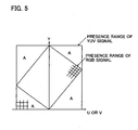
- Fig. 5 shows an example of ranges where the YUV signals of the luminance - color difference system and RGB signals of the display system are present.
- the range where the RGB signals are present is narrower than the range where the YUV signals are present.
- region A values which are actually not used for the display. Therefore, in the LUT composed of the luminance - color difference system, the utilization efficiency thereof is hardly sufficient.
- the LUT 20, 21 for color correction are composed of RGB signals of the display system. Therefore, the utilization efficiency of the LUT 20, 21 based on the present embodiment is about "100%".
- the adjustment values present in the location of the unnecessary grating points are not stored and the memory capacity can therefore be reduced.
- the discrete adjustment amounts are stored in the LUT 20,21.
- the color spacing can be refined even if the identical number of adjustment amounts are stored in the LUT based on the YUV signals of the luminance - color difference system and LUT 20, 21 of the present embodiment.
- the locations of the values stored in the LUT are shown by grating points, then even if the LUTs comprising the same number of grating points are composed of the YUV signals and RGB signals, the spacing of all the grating points in the range of the RGB signal will be narrower than that within the range of the YUV signal. As a result, the color spacing can be refined and color reproduction in the display system can be finely adjusted.
- the gradation changes of the inputted YCC signal can be reliably displayed and the texture of the displayed image can be compensated. Therefore, a highly accurate displayed image can be obtained with respect to the inputted image.
- the table size can be reduced by comparison with the case where the processing results are themselves stored. Because the adjustment causing sudden changes, such as from a skin color to a blue color, are rarely conducted in the case of color adjustment, the range of values that can be assumed by the differential values themselves is small. Therefore, the increase in memory capacity can be prevented.
- the RGB signal was the signal of the display system, but the present embodiment can be implemented and the same operation and effect can be demonstrated with any signal, provided it is a signal of the display system that can be displayed in a display unit.
- the YCC signal and RGB signal were explained as 256-gradation signals. It goes without saying that the implementation is possible and the operation and effect identical to that of the above-described example will be demonstrated with signals with gradation of 9 or more bit and 7 or less bit.
- the present color correction device 1 can be also employed in information devices such as personal computers, TV, VTR (Video Tape Recorder), DVD (Digital Video Disk) devices and portable information terminals such as cellular phones or PDA (Personal Digital Assistant ) devices.
- information devices such as personal computers, TV, VTR (Video Tape Recorder), DVD (Digital Video Disk) devices and portable information terminals such as cellular phones or PDA (Personal Digital Assistant ) devices.
- VTR Video Tape Recorder
- DVD Digital Video Disk
- portable information terminals such as cellular phones or PDA (Personal Digital Assistant ) devices.
Landscapes
- Engineering & Computer Science (AREA)
- Multimedia (AREA)
- Signal Processing (AREA)
- Processing Of Color Television Signals (AREA)
- Facsimile Image Signal Circuits (AREA)
- Color Image Communication Systems (AREA)
- Image Processing (AREA)
Description
- The present invention relates to a color correction method, a color correction device, and a color correction program for conducting color correction with respect to image signals by referring to a LUT. More particularly, the present invention relates to a color correction method and the like capable of reducing the color spacing of a LUT, while avoiding capacity increase of the memory that stores the LUT.
- A technology has been known by which, for example, a color of an image is beautifully displayed by conducting color correction with respect to TV video signals or image signals of digital cameras.
- For example, a method for conducting color correction by using matrix computations (for example, see Japanese Patent No.
3611490 Fig. 5 or Formula (1)) or a method for adjusting the lightness, saturation, and hue based on the maximum value, central value, and minimum value of the RGB signal (for example, see Japanese Patent Application Laid-Open No.2003-163814 - Furthermore, color correction is also conducted by using three-dimensional color tables. Color correction based on three-dimensional color tables was indicated to have high color reproducibility (for example, see the section relating to prior art in Japanese Patent No.
3611490 - Generally a three-dimensional color table stores the adjustment values of each component of an image signal (YUV, YCC, YCbCr, L*a*b, etc.) of a luminance - color difference system, but the values are stored discretely with consideration for memory capacity. The corrected image signal is then generated by conducting interpolation computations from the discrete values. The procedure described in Japanese Patent No.
3664364 - However, because errors occur during interpolation, the color table has to be configured with a spacing that is fine enough to maintain the image quality. On the other hand, the increase in memory capacity is also required to be prevented.
- Accordingly, a technology has heretofore been disclosed (for example, Japanese Patent Application Laid- Open No.
2003-219194 - However, with the technology described in Japanese Patent Application Laid-Open No.
2003-219194 2003-219194 -
US 2002/0060797 A1 shows an apparatus for converting a color gamut of an input color image, comprising a three-dimensional (3-D) difference lookup table for storing differences between input values corresponding to upper n bits of the input color image and 3-D converted color data thereof, a color interpolator for performing 3-D interpolation using 3-D converted data, which are output from the 3-D lookup difference lookup table, and 3-D color data corresponding to lower m bits of the input color image, and an adder for receiving output of the color interpolator and the input color image, and outputting an image whose colors have been finally converted. - According to
US 5,818,613 , a system and method for converting a color represented in a first color space to the color represented in a second color space uses a constant hue algorithm. The constant hue algorithm is used to compensate invalid colors in the second color space obtained as a result of the conversion. The constant hue algorithm determines a compensation factor that, in effect, blends the invalid color with pure grey until the invalid color becomes a valid color in the second color space. The compensation factor is optionally stored with the valid color in the second color space so that the original color in the first color space can be subsequently recovered. - Accordingly, the present invention was created to resolve the above-described problems and it is an object thereof to provide a color correction method, a color correction device, and a color correction program that can realize color correction processing with a fine-spacing color table, while preventing the increase in memory capacity.
- In order to attain the above-described object, the present invention provides a color correction method, and a color correction program as defined in the claims.
- The present invention provides a color correction method, a color correction device, and a color correction program that can realize color correction processing with a color table with a fine spacing, while preventing the increase in memory capacity.
-
-
Figs. 1A and 1B illustrate a configuration example of a color correction device; -
Fig. 2A illustrates an example of values stored in a LUT for color adjustment;Fig. 2B illustrates an example of values stored in a LUT for color adjustment differentiation; -
Fig. 3A shows a configuration example of a matrix conversion unit;Fig. 3B shows a configuration example of a color correction device; -
Fig. 4 is an example of a flowchart illustrating the processing operation; and -
Fig. 5 illustrates an example of a presence range of a YUV signal and a RGB signal. - The best mode for carrying out the present invention will be described below with reference to the appended drawings.
-
Fig. 1A shows a configuration example of acolor correction device 1. Thecolor correction device 1 has amatrix conversion unit 10, a RGB color adjustment LUT (Look Up Table) 20, and aninterpolation computation unit 30. - The
matrix conversion unit 10 converts the inputted image signal of a luminance - color difference system into an image signal of a display signal system, which is a signal system of a display unit. In the present embodiment, the image signal of the luminance - color difference system is taken as a YCC (luminance signal (Y) and two color difference signals (C)), and the image signal of the display signal system is taken as a RGB (Red, Green, Blue) signal. Each is considered to be a 8-bit 256-gradation signal. - In fact, by computation in use of the determinant of 3 rows and 3 columns (3 × 3), conversion to the RGB signal is performed in the
matrix conversion unit 10. - Gradation values after the adjustment relating to the RGB signal are stored in the RGB
color adjustment LUT 20. An example of the gradation values stored in theLUT 20 is shown inFig. 2A . As shown in the figure, the values stored in the RGBcolor adjustment LUT 20 are values of RGB (three-dimensional) after color adjustment. For example, each value is stored so as to be available in response to a request, for example, when the displayed image has to be adjusted to a healthy skin color. The adjustment value that is wished to be adjusted may be registered for each RGB in advance. The RGBcolor adjustment LUT 20 stores discrete values with consideration for memory capacity. - The
interpolation computation unit 30 conducts interpolation computation from each adjusted value that was read out from the RGBcolor adjustment LUT 20. The RGB signal after interpolation computation is output to display unit as a RGB signal after correction. -
Fig. 1B shows another configuration example of thecolor correction device 1. In comparison with thecolor correction device 1 shown inFig 1A , thecolor correction device 1 has different configuration of thematrix conversion unit 11 and additionally has an excessamount compensation unit 40. The RGBcolor adjustment LUT 20 andinterpolation computation unit 30 are identical to those of thecolor correction device 1 shown inFig. 1A . -
Fig. 3A shows a configuration example of thematrix conversion unit 11. Thematrix conversion unit 11 has agradation correction unit 110, amatrix processing unit 111, and aclip processing unit 112. - The
gradation correction unit 110 conducts correction computation with respect to the YCC signal. With such correction computation, a bright color can be reproduced and lightness can be somewhat improved. Specific processing conducted in thegradation correction unit 110 will be described below. - The
matrix processing unit 111 has a configuration identical to that of thematrix conversion unit 10 shown inFig. 1A and conducts identical processing. The YCC signal after the correction is inputted and converted into the RGB signal of the display system by conducting matrix computation. - The
clip processing unit 112 conducts clip processing with respect to the converted RGB signal. The clip processing is a process in which, when overflow or underflow has occurred with respect to each gradation value of the RGB signal, the overflow value or the underflow value is deducted to inhibit overflow, etc., by conducting correction computation in the gradation correction unit 110 (or computation by matrix conversion in the matrix processing unit 111). The value corresponding to the overflow, etc., is outputted as a color region excess amount from theclip processing unit 112 to the excessamount compensation unit 40. - Returning to
Fig. 1B , the excessamount compensation unit 40 inputs the color-adjusted RGB signal after interpolation computation and the color region excess amount and conducts the processing of adding the color region excess amount to the color-adjusted RGB signal. The excessamount compensation unit 40 outputs the RGB signal after the addition to the display unit as a RGB signal subjected to color region excess compensation and correction. - In the
color correction device 1 shown inFig. 1B , the color region excess fraction is compressed by the matrix conversion unit 11 (clip processing unit 112) and compensation of this color region excess fraction is conducted with the excessamount compensation unit 40. -
Fig. 3B shows a configuration example of the othercolor correction device 1. In comparison with thecolor correction device 1 shown inFig. 1A , this device has a RGB color adjustmentdifferential LUT 21 as a LUT for color adjustment with respect to the RGB signal and additionally has anaddition unit 50. -
Fig. 2B shows an example of values stored in the RGB color adjustmentdifferential LUT 21. In the RGBcolor adjustment LUT 20, the processing results relating to each color of RGB were stored (seeFig. 2A ), whereas in the RGB color adjustmentdifferential LUT 21, the differential values are stored. - In the
compensation computation unit 30, the compensation computation is conducted with respect to the differential values and a color-adjusted differential RGB signal is outputted. Theaddition unit 50 adds up the color-adjusted differential RGB signal and the RGB signal before interpolation computation. Theaddition unit 50 outputs the corrected RGB signal obtained by addition. -
Fig. 4 shows an example of a flowchart illustrating the processing operation executed in the above-describedcolor correction device 1. - If the process is started (S10), the gradation correction is conducted with respect to the YCC signal (S11). This is the processing executed in the gradation correction unit 110 (see
Fig. 3A ). This processing is not executed in thecolor correction device 1 shown inFig. 1A . - Taking the inputted YCC signal as an example, when a YUV signal (YoUoVo) signal is present, the
gradation correction unit 110 conducts computations by using the following numerical formulas:

- Intensity adjustment of saturation can be conducted and a bright color can be reproduced according to formulas (1), (2). Furthermore, lightness can be somewhat increased by conducting computation of

with respect to the luminance signal Yo. - Then, the YCC signal (YUV signal) is converted into the RGB signal of the display system (S12). This is the processing conducted in the
matrix conversion units 


- When a dynamic range is changed (extended) with respect to the YCC signal (YUV signal) of the luminance - color difference system, then the following formulas are computed:


- The matrix conversion of the present embodiment includes not only the above-described Formula (4) to Formula (6), but also the abotre-described Formula (7) to Formula (9) for conducting subtraction processing ((Y1 - 16) processing) with respect to Y1.
- The overflow fraction and underflow fraction are then clipped (S13) and the values thereof are saved (S14). This is the processing executed in the
clip processing unit 112. More specifically, the following processing is executed: - if R1 > 255, then R2 = 255, Rc = R1 - 255
else if R1 < 0 then R2 = 0, Rc = R1
else R2 = R1, Rc = 0 - if G1 > 255, then G2 = 255, Gc = G1 - 255
else if G1 < 0 then G2 = 0, Gc = G1
else G2 = G1, Gc = 0 - if B1 > 255, then B2 = 255, Bc = B1 - 255
else if B1 < 0 then B2 = 0, Bc = B1
else B2 = B1, Bc = 0 - Te clip values (Rc, Gc, Bc) obtained by such processing are outputted as color region excess amounts.
- Then, the interpolation computation (color conversion) is conducted with the three-
dimensional LUT 20, 21 (S15). Theinterpolation computation unit 30 reads the gradation value (or differential value) corresponding to each gradation value of the RGB signal from the RGB color adjustment LUT 20 (or RGB color adjustment differential LUT 21) and conducts the interpolation computation. The interpolation computation may involve processing such as the well-known "three-dimensional interpolation", "prism interpolation", or "pyramid interpolation". Alternatively, the interpolation computation disclosed in the aforementioned Japanese Patent No.3664363 - The color conversion results are then added to the RGB signal before the correction (S16). This processing is executed in the addition unit 50 (see
Fig. 3B ). This processing is conducted because the differential value after interpolation has to be added to the RGB signal prior to correction since the differential values are stored in the RGB color adjustment differential LUT 21 (seeFig. 2B ). - More specifically, the following computations are executed.


- The clip compensation, that is, the addition of the overflow value or underflow value is then conducted (S17). This is the processing executed in the excess amount compensation unit 40 (see
Fig. 1B ). More specifically, the following computations are executed.


- By the above-described procedure, the color-corrected RGB signals (R3, G3, B3) or (R4, G4, B4) after correction, or RGB signals (R5, G5, B5) after the correction that were subjected to color region excess compensation are obtained from YUV signals (Yo, Uo, Vo).
- In the present embodiment, as described hereinabove, the RGB signals (adjustment amounts) of the display system are stored in the
LUT -
Fig. 5 shows an example of ranges where the YUV signals of the luminance - color difference system and RGB signals of the display system are present. As shown in the figure, the range where the RGB signals are present is narrower than the range where the YUV signals are present. Even if the LUT for color correction is composed of signals of the luminance - color difference system, there are values (region A) which are actually not used for the display. Therefore, in the LUT composed of the luminance - color difference system, the utilization efficiency thereof is hardly sufficient. However, as was explained in the above-described example, in the present embodiment, theLUT LUT - Furthermore, because the values of the region (region A) that is not used for display are not stored in the
LUT - Furthermore, the discrete adjustment amounts are stored in the
LUT LUT - As shown in
Fig. 5 , if the locations of the values stored in the LUT are shown by grating points, then even if the LUTs comprising the same number of grating points are composed of the YUV signals and RGB signals, the spacing of all the grating points in the range of the RGB signal will be narrower than that within the range of the YUV signal. As a result, the color spacing can be refined and color reproduction in the display system can be finely adjusted. - Furthermore, as explained with reference to
Fig. 1B , because the clip compensation has been conducted, the gradation changes of the inputted YCC signal can be reliably displayed and the texture of the displayed image can be compensated. Therefore, a highly accurate displayed image can be obtained with respect to the inputted image. - Furthermore, as explained with reference to
Fig. 2B , because the adjusted amounts of differential values are stored in theLUT 21 for color correction, the table size can be reduced by comparison with the case where the processing results are themselves stored. Because the adjustment causing sudden changes, such as from a skin color to a blue color, are rarely conducted in the case of color adjustment, the range of values that can be assumed by the differential values themselves is small. Therefore, the increase in memory capacity can be prevented. - In the above-described example, the explanation was conduced with respect to the case where the YCC signal or YUV signal was used as a signal of the luminance - color difference system. It goes without saying that the present embodiment can be implemented and the same operation and effect can be demonstrated with other signals of the luminance - color difference system, such as Lab signal.
- Furthermore, an example was explained in which the RGB signal was the signal of the display system, but the present embodiment can be implemented and the same operation and effect can be demonstrated with any signal, provided it is a signal of the display system that can be displayed in a display unit.
- Furthermore, in the above-described example, the YCC signal and RGB signal were explained as 256-gradation signals. It goes without saying that the implementation is possible and the operation and effect identical to that of the above-described example will be demonstrated with signals with gradation of 9 or more bit and 7 or less bit.
- The present
color correction device 1 can be also employed in information devices such as personal computers, TV, VTR (Video Tape Recorder), DVD (Digital Video Disk) devices and portable information terminals such as cellular phones or PDA (Personal Digital Assistant ) devices.
Claims (7)
- A color correction method for conducting correction processing for a plurality of color signals represented in a luminance - color difference space, comprising the steps of:- (S12) converting said plurality of color signals represented in the luminance - color difference space into a plurality of color signals of a display signal space, which is a signal space of a display device, by matrix conversion;- (S15) conducting color adjustment for said plurality of color signals of the display signal space by interpolation computation using a plurality of discrete gradation values of said display signal space stored in a Look Up table (20) to compute a plurality of adjusted color signals of said display signal space,
wherein
said color adjustment is conducted by reading said plurality of discrete gradation values corresponding to a plurality of gradation values of said plurality of converted color signals from the Look Up table (20) and by conducting said interpolation computation to said plurality of read discrete gradation values, and
said plurality of discrete gradation values are a plurality of gradation values after color adjustment for the plurality of color signals,
further comprising the steps of:- (S13) clipping an overflow value and an underflow value of said plurality of color signals of the display signal space after said matrix conversion in said converting step (S12);- (S14) saving said overflow and underflow values; and- (S17) adding said overflow and underflow values to said plurality of adjusted color signals after interpolation computation. - The color correction method according to claim 1, wherein- in said converting step (S12), a dynamic range conversion is conducted for said plurality of color signals of the luminance - color difference space by said matrix conversion.
- The color correction method according to claim 1, further comprising a step of correcting a plurality of gradation values of a luminance signal or a color difference signal of said plurality of color signals by gradation correction in said luminance - color difference space, wherein
in said converting step, said matrix conversion is conducted with respect to said plurality of color signals corrected in said correcting step. - A color correction method for conducting correction processing for a plurality of color signals represented in a luminance - color difference space, comprising the steps of:- (S12) converting said plurality of color signals represented in the luminance - color difference space into a plurality of color signals of a display signal space, which is a signal space of a display device, by matrix conversion;- (S15) conducting color adjustment for said plurality of color signals of the display signal space by interpolation computation using a plurality of discrete differential values of said display signal space stored in a Look Up table (21) to compute a plurality of adjusted color signals of said display signal space; and (S16) adding said plurality of color signals of the display signal space adjusted by interpolation computation using said plurality of discrete differential values of said Look Up table (21) and said plurality of color signals of the display signal space before said interpolation computation,
wherein
said color adjustment is conducted by reading said plurality of discrete differential values corresponding to a plurality of gradation values of said plurality of converted color signals from the Look Up table (21) and by conducting said interpolation computation to said plurality of read discrete differential values, and
said plurality of discrete differential values are a plurality of a differential values between said plurality of gradation values of said input color signal and gradation values after color adjustments for the plurality of color signals,
further comprising the steps of:- (S13) clipping an overflow value and an underflow value of said plurality of color signals of the display signal space after said matrix conversion in said converting step (S12);- (S14) saving said overflow and underflow values; and- (S17) adding said overflow and underflow values to said plurality of adjusted color signals after interpolation computation. - A color correction program for conducting correction processing for a plurality of color signals represented in a luminance - color difference space, said program when run on a computer causing a computer to execute the method of claim 1 or 4.
- A color correction device (1) for conducting correction processing for a plurality of color signals represented in a luminance - color difference space, comprising:- a conversion unit (11) which converts said plurality of color signals represented in the luminance - color difference space into a plurality of color signals of a display signal space, which is a signal space of a display device, by a matrix conversion;- an interpolation computation unit (30) which conducts color adjustment for said plurality of color signals of the display signal by interpolation computation using a plurality of discrete gradation values of said display signal space stored in a Look Up table (20) to compute a plurality of adjusted color signals of said display signal space,
wherein
said interpolation computation unit (30) conducts said color adjustment by reading said plurality of discrete gradation values corresponding to a plurality of gradation values of said plurality of converted color signals from the Look Up table (20) and by conducting said interpolation computation to said plurality of read discrete gradation values, and
said plurality of discrete gradation values are a plurality of gradation values after color adjustment for the plurality of color signals,
further comprising- a clipping unit (112) which conducts clipping an overflow value and an underflow value of said plurality of color signals of the display signal space obtained by said matrix conversion and conducts saving said overflow and underflow values and- an excess amount compensation unit (40) which adds said overflow and underflow values to said plurality of adjusted color signals. - A color correction device (1) for conducting correction processing for a plurality of color signals represented in a luminance - color difference space, comprising:- a conversion unit (11) which converts said plurality of color signals represented in the luminance - color difference space into a plurality of color signals of a display signal space, which is a signal space of a display device, by a matrix conversion;- an interpolation computation unit (30) which conducts color adjustment for said plurality of color signals of the display signal by interpolation computation using plurality of discrete differential values of said display signal space stored in a Look Up table (21) to compute a plurality of adjusted color signals of said display signal space; and- an addition unit (50) which adds said plurality of color signals of the display signal space adjusted by interpolation computation using said plurality of discrete differential values of said Look Up table (21) and said plurality of color signals of the display signal space before said interpolation computation,
wherein
said interpolation computation unit (30) conducts said color adjustment by reading said plurality of discrete differential values corresponding to a plurality of gradation values of said plurality of converted color signals from the Look Up table (21) and by conducting said interpolation computation to said plurality of read discrete differential values, and
said plurality of discrete differential values are a plurality of a differential values between said plurality of gradation values of said input color signal and gradation values after color adjustments for the plurality of color signals,
further comprising- a clipping unit (112) which conducts clipping an overflow value and an underflow value of said plurality of color signals of the display signal space obtained by said matrix conversion and conducts saving said overflow and underflow values and- an excess amount compensation unit (40) which adds said overflow and underflow values to said plurality of adjusted color signals.
Applications Claiming Priority (1)
| Application Number | Priority Date | Filing Date | Title |
|---|---|---|---|
| JP2006073828A JP4676364B2 (en) | 2006-03-17 | 2006-03-17 | Color correction method, color correction apparatus, and color correction program |
Publications (3)
| Publication Number | Publication Date |
|---|---|
| EP1835727A2 EP1835727A2 (en) | 2007-09-19 |
| EP1835727A3 EP1835727A3 (en) | 2008-09-17 |
| EP1835727B1 true EP1835727B1 (en) | 2012-10-24 |
Family
ID=36691445
Family Applications (1)
| Application Number | Title | Priority Date | Filing Date |
|---|---|---|---|
| EP06116633A Active EP1835727B1 (en) | 2006-03-17 | 2006-07-05 | Color correction method, color correction device, and color correction program |
Country Status (3)
| Country | Link |
|---|---|
| US (1) | US7965341B2 (en) |
| EP (1) | EP1835727B1 (en) |
| JP (1) | JP4676364B2 (en) |
Families Citing this family (10)
| Publication number | Priority date | Publication date | Assignee | Title |
|---|---|---|---|---|
| KR20070048514A (en) * | 2005-11-04 | 2007-05-09 | 삼성전자주식회사 | Liquid crystal display and method for driving there of |
| KR100834615B1 (en) * | 2006-01-24 | 2008-06-02 | 삼성전자주식회사 | Color conversion method based on error correction table |
| US7796144B2 (en) * | 2006-05-30 | 2010-09-14 | Himax Technologies Limited | Gamma correction device of display apparatus and method thereof |
| US20080046948A1 (en) * | 2006-08-07 | 2008-02-21 | Apple Computer, Inc. | Creation, management and delivery of personalized media items |
| JP4666050B2 (en) | 2008-02-01 | 2011-04-06 | セイコーエプソン株式会社 | Color conversion apparatus, image output apparatus, and color conversion method |
| US8860751B2 (en) | 2009-09-01 | 2014-10-14 | Entertainment Experience Llc | Method for producing a color image and imaging device employing same |
| EP2474166A4 (en) | 2009-09-01 | 2014-01-01 | Entertainment Experience Llc | Method for producing a color image and imaging device employing same |
| JP2013153251A (en) * | 2012-01-24 | 2013-08-08 | Ricoh Co Ltd | Image processing device, image processing method, image formation device, image projection device, program, and storage medium |
| CN110738957B (en) * | 2019-09-17 | 2023-04-25 | 苏州佳世达电通有限公司 | Display system and color characteristic measurement method |
| CN115499633B (en) * | 2022-09-23 | 2024-05-28 | 昇显微电子(苏州)股份有限公司 | Color correction method and system based on Mini 3DLUT |
Citations (1)
| Publication number | Priority date | Publication date | Assignee | Title |
|---|---|---|---|---|
| US5923316A (en) * | 1996-10-15 | 1999-07-13 | Ati Technologies Incorporated | Optimized color space conversion |
Family Cites Families (23)
| Publication number | Priority date | Publication date | Assignee | Title |
|---|---|---|---|---|
| JP3400506B2 (en) * | 1993-03-12 | 2003-04-28 | オリンパス光学工業株式会社 | Image processing device |
| US5450500A (en) * | 1993-04-09 | 1995-09-12 | Pandora International Ltd. | High-definition digital video processor |
| US5818613A (en) * | 1995-12-04 | 1998-10-06 | Silicon Graphics, Inc. | System and method for color space conversion |
| US5805213A (en) * | 1995-12-08 | 1998-09-08 | Eastman Kodak Company | Method and apparatus for color-correcting multi-channel signals of a digital camera |
| KR100363250B1 (en) | 1995-12-30 | 2003-03-15 | 삼성전자 주식회사 | Method and system for processing colors using two-dimensional chrominance division |
| JP3907810B2 (en) | 1998-01-07 | 2007-04-18 | 富士フイルム株式会社 | Three-dimensional lookup table correction method, image processing apparatus for performing the same, and digital color printer having the same |
| US6282312B1 (en) | 1998-09-28 | 2001-08-28 | Eastman Kodak Company | System using one or more residual image(s) to represent an extended color gamut digital image |
| US6326977B1 (en) | 1998-11-03 | 2001-12-04 | Sharp Laboratories Of America, Inc. | Rendering of YCBCR images on an RGS display device |
| JP3664364B2 (en) | 1998-11-26 | 2005-06-22 | 富士通株式会社 | Color conversion method |
| US7009640B1 (en) * | 1999-05-31 | 2006-03-07 | Olympus Corporation | Color reproduction system for carrying out color correction by changing over color correction parameters according to images of photographed subjects |
| EP1075140A1 (en) | 1999-08-02 | 2001-02-07 | Koninklijke Philips Electronics N.V. | Video signal enhancement |
| JP2001103504A (en) | 1999-09-30 | 2001-04-13 | Fujitsu General Ltd | Color correction and gamma correction circuit |
| JP3611490B2 (en) | 1999-10-14 | 2005-01-19 | 三菱電機株式会社 | Color conversion apparatus and color conversion method |
| JP3720691B2 (en) * | 2000-09-12 | 2005-11-30 | キヤノン株式会社 | Color processing method and apparatus |
| JP4065482B2 (en) | 2001-09-18 | 2008-03-26 | キヤノン株式会社 | Image data processing method, apparatus, storage medium, and program |
| JP2003125207A (en) | 2001-10-15 | 2003-04-25 | Fuji Xerox Co Ltd | Image processor and program |
| JP3781107B2 (en) | 2001-11-27 | 2006-05-31 | シャープ株式会社 | Color adjustment device |
| JP2003219194A (en) | 2002-01-28 | 2003-07-31 | Hitachi Ltd | Color correction system and color correction method |
| JP2004135313A (en) | 2002-09-18 | 2004-04-30 | Canon Inc | Device and method for image processing |
| TWI225362B (en) * | 2003-06-19 | 2004-12-11 | Benq Corp | Color correcting device and method for image forming apparatus |
| JP2005269443A (en) * | 2004-03-19 | 2005-09-29 | Seiko Epson Corp | Method and apparatus for image processing, program and recording medium |
| KR100695798B1 (en) * | 2004-08-12 | 2007-03-15 | 이디텍 주식회사 | Apparatus for color gamut mapping of color image |
| US7408558B2 (en) * | 2005-08-25 | 2008-08-05 | Eastman Kodak Company | Laser-based display having expanded image color |
-
2006
- 2006-03-17 JP JP2006073828A patent/JP4676364B2/en active Active
- 2006-07-05 EP EP06116633A patent/EP1835727B1/en active Active
- 2006-08-03 US US11/498,015 patent/US7965341B2/en active Active
Patent Citations (1)
| Publication number | Priority date | Publication date | Assignee | Title |
|---|---|---|---|---|
| US5923316A (en) * | 1996-10-15 | 1999-07-13 | Ati Technologies Incorporated | Optimized color space conversion |
Also Published As
| Publication number | Publication date |
|---|---|
| JP2007251709A (en) | 2007-09-27 |
| US20070216812A1 (en) | 2007-09-20 |
| US7965341B2 (en) | 2011-06-21 |
| JP4676364B2 (en) | 2011-04-27 |
| EP1835727A3 (en) | 2008-09-17 |
| EP1835727A2 (en) | 2007-09-19 |
Similar Documents
| Publication | Publication Date | Title |
|---|---|---|
| EP1835727B1 (en) | Color correction method, color correction device, and color correction program | |
| US7081899B2 (en) | Image processing support system, image processing device and image display device | |
| US8508624B1 (en) | Camera with color correction after luminance and chrominance separation | |
| US20080259216A1 (en) | Color signal converting apparatus, video display apparatus including the same, and color signal converting method | |
| JP5178473B2 (en) | Image processing apparatus and image processing method | |
| KR101927968B1 (en) | METHOD AND DEVICE FOR DISPLAYING IMAGE BASED ON METADATA, AND RECORDING MEDIUM THEREFOR | |
| JP2010147908A (en) | Image processing apparatus, image processing method, image processing program and recording medium | |
| EP2254329B1 (en) | Information processing device and method and program | |
| US8248432B2 (en) | Display apparatus and method of image enhancement thereof | |
| US20110234622A1 (en) | Color correction device and color correction method | |
| US7573532B2 (en) | Image processing device | |
| US20030231193A1 (en) | Image processing device, image processing method, program and recordintg medium | |
| JP2009147770A (en) | Chromatic aberration correction apparatus, imaging device, chromatic aberration calculation method, and chromatic aberration calculation program | |
| US7847973B2 (en) | Color mapping circuit | |
| US8253862B2 (en) | Method and device for image sharpness adjustment | |
| EP1763257B1 (en) | Chrominance signal processing apparatus and method | |
| US9001140B2 (en) | Information processing device and method, and program, for gamut conversion of content | |
| JP4305917B2 (en) | Video signal processing apparatus and television apparatus | |
| US7298893B2 (en) | Image processing device and image processing method | |
| JP2006148607A (en) | Image processing apparatus and image processing method | |
| JP2001312254A (en) | Method for setting icc profile for color liquid crystal display panel | |
| JP2005151074A (en) | Processing circuit for color correction classified by hue | |
| US8531549B1 (en) | Camera that uses YUV to YUV table-based color correction for processing digital images | |
| CN102438155A (en) | Signal processing apparatus, signal processing method, and program | |
| JP2014033272A (en) | Image processing apparatus, digital camera, image processing program, and image processing method |
Legal Events
| Date | Code | Title | Description |
|---|---|---|---|
| PUAI | Public reference made under article 153(3) epc to a published international application that has entered the european phase |
Free format text: ORIGINAL CODE: 0009012 |
|
| AK | Designated contracting states |
Kind code of ref document: A2 Designated state(s): AT BE BG CH CY CZ DE DK EE ES FI FR GB GR HU IE IS IT LI LT LU LV MC NL PL PT RO SE SI SK TR |
|
| AX | Request for extension of the european patent |
Extension state: AL BA HR MK YU |
|
| PUAL | Search report despatched |
Free format text: ORIGINAL CODE: 0009013 |
|
| AK | Designated contracting states |
Kind code of ref document: A3 Designated state(s): AT BE BG CH CY CZ DE DK EE ES FI FR GB GR HU IE IS IT LI LT LU LV MC NL PL PT RO SE SI SK TR |
|
| AX | Request for extension of the european patent |
Extension state: AL BA HR MK RS |
|
| 17P | Request for examination filed |
Effective date: 20090316 |
|
| AKX | Designation fees paid |
Designated state(s): DE FR GB |
|
| 17Q | First examination report despatched |
Effective date: 20091103 |
|
| GRAP | Despatch of communication of intention to grant a patent |
Free format text: ORIGINAL CODE: EPIDOSNIGR1 |
|
| GRAC | Information related to communication of intention to grant a patent modified |
Free format text: ORIGINAL CODE: EPIDOSCIGR1 |
|
| GRAS | Grant fee paid |
Free format text: ORIGINAL CODE: EPIDOSNIGR3 |
|
| GRAA | (expected) grant |
Free format text: ORIGINAL CODE: 0009210 |
|
| AK | Designated contracting states |
Kind code of ref document: B1 Designated state(s): DE FR GB |
|
| REG | Reference to a national code |
Ref country code: GB Ref legal event code: FG4D |
|
| REG | Reference to a national code |
Ref country code: DE Ref legal event code: R096 Ref document number: 602006032593 Country of ref document: DE Effective date: 20121227 |
|
| PLBE | No opposition filed within time limit |
Free format text: ORIGINAL CODE: 0009261 |
|
| STAA | Information on the status of an ep patent application or granted ep patent |
Free format text: STATUS: NO OPPOSITION FILED WITHIN TIME LIMIT |
|
| 26N | No opposition filed |
Effective date: 20130725 |
|
| REG | Reference to a national code |
Ref country code: DE Ref legal event code: R097 Ref document number: 602006032593 Country of ref document: DE Effective date: 20130725 |
|
| REG | Reference to a national code |
Ref country code: FR Ref legal event code: PLFP Year of fee payment: 11 |
|
| REG | Reference to a national code |
Ref country code: FR Ref legal event code: PLFP Year of fee payment: 12 |
|
| REG | Reference to a national code |
Ref country code: FR Ref legal event code: PLFP Year of fee payment: 13 |
|
| PGFP | Annual fee paid to national office [announced via postgrant information from national office to epo] |
Ref country code: FR Payment date: 20230620 Year of fee payment: 18 |
|
| PGFP | Annual fee paid to national office [announced via postgrant information from national office to epo] |
Ref country code: GB Payment date: 20230601 Year of fee payment: 18 |
|
| PGFP | Annual fee paid to national office [announced via postgrant information from national office to epo] |
Ref country code: DE Payment date: 20230531 Year of fee payment: 18 |