EP1832894A2 - System and method for automatic gain compensation based on image processing - Google Patents
System and method for automatic gain compensation based on image processing Download PDFInfo
- Publication number
- EP1832894A2 EP1832894A2 EP07004722A EP07004722A EP1832894A2 EP 1832894 A2 EP1832894 A2 EP 1832894A2 EP 07004722 A EP07004722 A EP 07004722A EP 07004722 A EP07004722 A EP 07004722A EP 1832894 A2 EP1832894 A2 EP 1832894A2
- Authority
- EP
- European Patent Office
- Prior art keywords
- volume data
- brightness
- agc
- lgc
- image
- Prior art date
- Legal status (The legal status is an assumption and is not a legal conclusion. Google has not performed a legal analysis and makes no representation as to the accuracy of the status listed.)
- Granted
Links
- 238000000034 method Methods 0.000 title claims description 26
- 238000004458 analytical method Methods 0.000 claims abstract description 4
- 238000002604 ultrasonography Methods 0.000 claims description 63
- 208000037170 Delayed Emergence from Anesthesia Diseases 0.000 claims description 3
- GNFTZDOKVXKIBK-UHFFFAOYSA-N 3-(2-methoxyethoxy)benzohydrazide Chemical compound COCCOC1=CC=CC(C(=O)NN)=C1 GNFTZDOKVXKIBK-UHFFFAOYSA-N 0.000 claims 1
- 239000000523 sample Substances 0.000 description 7
- 238000010586 diagram Methods 0.000 description 4
- 238000012986 modification Methods 0.000 description 3
- 230000004048 modification Effects 0.000 description 3
- 210000004872 soft tissue Anatomy 0.000 description 3
- 230000001934 delay Effects 0.000 description 2
- 238000003745 diagnosis Methods 0.000 description 2
- 238000002592 echocardiography Methods 0.000 description 2
- 239000000284 extract Substances 0.000 description 2
- 230000003111 delayed effect Effects 0.000 description 1
- 230000001066 destructive effect Effects 0.000 description 1
- 238000001514 detection method Methods 0.000 description 1
- 238000003672 processing method Methods 0.000 description 1
- 230000001902 propagating effect Effects 0.000 description 1
- 238000001356 surgical procedure Methods 0.000 description 1
Images


Classifications
-
- B—PERFORMING OPERATIONS; TRANSPORTING
- B65—CONVEYING; PACKING; STORING; HANDLING THIN OR FILAMENTARY MATERIAL
- B65G—TRANSPORT OR STORAGE DEVICES, e.g. CONVEYORS FOR LOADING OR TIPPING, SHOP CONVEYOR SYSTEMS OR PNEUMATIC TUBE CONVEYORS
- B65G67/00—Loading or unloading vehicles
- B65G67/02—Loading or unloading land vehicles
- B65G67/04—Loading land vehicles
- B65G67/08—Loading land vehicles using endless conveyors
-
- G—PHYSICS
- G01—MEASURING; TESTING
- G01S—RADIO DIRECTION-FINDING; RADIO NAVIGATION; DETERMINING DISTANCE OR VELOCITY BY USE OF RADIO WAVES; LOCATING OR PRESENCE-DETECTING BY USE OF THE REFLECTION OR RERADIATION OF RADIO WAVES; ANALOGOUS ARRANGEMENTS USING OTHER WAVES
- G01S7/00—Details of systems according to groups G01S13/00, G01S15/00, G01S17/00
- G01S7/52—Details of systems according to groups G01S13/00, G01S15/00, G01S17/00 of systems according to group G01S15/00
- G01S7/52017—Details of systems according to groups G01S13/00, G01S15/00, G01S17/00 of systems according to group G01S15/00 particularly adapted to short-range imaging
- G01S7/52023—Details of receivers
- G01S7/52033—Gain control of receivers
-
- B—PERFORMING OPERATIONS; TRANSPORTING
- B65—CONVEYING; PACKING; STORING; HANDLING THIN OR FILAMENTARY MATERIAL
- B65G—TRANSPORT OR STORAGE DEVICES, e.g. CONVEYORS FOR LOADING OR TIPPING, SHOP CONVEYOR SYSTEMS OR PNEUMATIC TUBE CONVEYORS
- B65G13/00—Roller-ways
-
- B—PERFORMING OPERATIONS; TRANSPORTING
- B65—CONVEYING; PACKING; STORING; HANDLING THIN OR FILAMENTARY MATERIAL
- B65G—TRANSPORT OR STORAGE DEVICES, e.g. CONVEYORS FOR LOADING OR TIPPING, SHOP CONVEYOR SYSTEMS OR PNEUMATIC TUBE CONVEYORS
- B65G2207/00—Indexing codes relating to constructional details, configuration and additional features of a handling device, e.g. Conveyors
- B65G2207/08—Adjustable and/or adaptable to the article size
-
- B—PERFORMING OPERATIONS; TRANSPORTING
- B65—CONVEYING; PACKING; STORING; HANDLING THIN OR FILAMENTARY MATERIAL
- B65G—TRANSPORT OR STORAGE DEVICES, e.g. CONVEYORS FOR LOADING OR TIPPING, SHOP CONVEYOR SYSTEMS OR PNEUMATIC TUBE CONVEYORS
- B65G2814/00—Indexing codes relating to loading or unloading articles or bulk materials
- B65G2814/03—Loading or unloading means
- B65G2814/0347—Loading or unloading means for cars or linked car-trains with individual load-carriers
-
- G—PHYSICS
- G01—MEASURING; TESTING
- G01S—RADIO DIRECTION-FINDING; RADIO NAVIGATION; DETERMINING DISTANCE OR VELOCITY BY USE OF RADIO WAVES; LOCATING OR PRESENCE-DETECTING BY USE OF THE REFLECTION OR RERADIATION OF RADIO WAVES; ANALOGOUS ARRANGEMENTS USING OTHER WAVES
- G01S15/00—Systems using the reflection or reradiation of acoustic waves, e.g. sonar systems
- G01S15/88—Sonar systems specially adapted for specific applications
- G01S15/89—Sonar systems specially adapted for specific applications for mapping or imaging
- G01S15/8906—Short-range imaging systems; Acoustic microscope systems using pulse-echo techniques
- G01S15/8993—Three dimensional imaging systems
Definitions
- the present invention generally relates to image processing systems, and more particularly to an image processing system and a method for adjusting the brightness of images.
- an ultrasound diagnostic system has become an important and popular diagnostic tool due to its wide range of applications. Specifically, due to its non-invasive and non-destructive nature, the ultrasound diagnostic system has been extensively used in the medical profession. Modern high-performance ultrasound diagnostic systems and techniques are commonly used to produce two or three-dimensional (2D or 3D) diagnostic images of a target object.
- the ultrasound diagnostic system generally uses a probe including an array transducer having a plurality of transducer elements to transmit and receive ultrasound signals.
- the ultrasound diagnostic system forms an ultrasound image of the internal structures of the target object by electrically exciting the transducer elements to generate ultrasound pulses that travel into the target object.
- the ultrasound pulses produce ultrasound echoes since they are reflected from a discontinuous surface of acoustic impedance of the internal structure, which appears as discontinuities to the propagating ultrasound pulses.
- Various ultrasound echoes return to the array transducer and are converted into electrical signals, which are amplified and processed to produce ultrasound data for forming an image of the internal structure of the target object.
- the ultrasound diagnostic system is very important in the medical field since it provides physicians with real-time and high-resolution images of human internal features without the need for invasive observation techniques such as surgery.
- an ultrasound image needs to be optimized to clearly show a desirable portion for accurate diagnosis.
- the ultrasound image can be optimized by slightly adjusting the image parameters related to the brightness of an ultrasound image such as an axial gain compensation (AGC) parameter, a lateral gain compensation (LGC) parameter, a gain parameter and a dynamic range (DR) parameter.
- AGC axial gain compensation
- LGC lateral gain compensation
- DR dynamic range
Landscapes
- Engineering & Computer Science (AREA)
- Computer Networks & Wireless Communication (AREA)
- Physics & Mathematics (AREA)
- General Physics & Mathematics (AREA)
- Radar, Positioning & Navigation (AREA)
- Remote Sensing (AREA)
- Aviation & Aerospace Engineering (AREA)
- Mechanical Engineering (AREA)
- Ultra Sonic Daignosis Equipment (AREA)
- Image Processing (AREA)
- Image Analysis (AREA)
- Closed-Circuit Television Systems (AREA)
Abstract
Description
- The present application claims priority from
Korean Patent Application No. 10-2006-0022504 filed on March 10, 2006 - The present invention generally relates to image processing systems, and more particularly to an image processing system and a method for adjusting the brightness of images.
- Generally, an ultrasound diagnostic system has become an important and popular diagnostic tool due to its wide range of applications. Specifically, due to its non-invasive and non-destructive nature, the ultrasound diagnostic system has been extensively used in the medical profession. Modern high-performance ultrasound diagnostic systems and techniques are commonly used to produce two or three-dimensional (2D or 3D) diagnostic images of a target object. The ultrasound diagnostic system generally uses a probe including an array transducer having a plurality of transducer elements to transmit and receive ultrasound signals. The ultrasound diagnostic system forms an ultrasound image of the internal structures of the target object by electrically exciting the transducer elements to generate ultrasound pulses that travel into the target object. The ultrasound pulses produce ultrasound echoes since they are reflected from a discontinuous surface of acoustic impedance of the internal structure, which appears as discontinuities to the propagating ultrasound pulses. Various ultrasound echoes return to the array transducer and are converted into electrical signals, which are amplified and processed to produce ultrasound data for forming an image of the internal structure of the target object. The ultrasound diagnostic system is very important in the medical field since it provides physicians with real-time and high-resolution images of human internal features without the need for invasive observation techniques such as surgery.
- In the ultrasound diagnostic system, an ultrasound image needs to be optimized to clearly show a desirable portion for accurate diagnosis. The ultrasound image can be optimized by slightly adjusting the image parameters related to the brightness of an ultrasound image such as an axial gain compensation (AGC) parameter, a lateral gain compensation (LGC) parameter, a gain parameter and a dynamic range (DR) parameter.
- However, since the adjustment of the image parameters is carried out based on the frame data and the volume data for a 3-dimensional ultrasound image are obtained based on the frame data, it is difficult to optimally improve the quality of the 3-dimensional ultrasound image.
- Arrangements and embodiments may be described in detail with reference to the following drawings in which like reference numerals refer to like elements and wherein:
- FIG. 1 is a block diagram showing an ultrasound diagnostic system constructed in accordance with the present invention;
- FIG. 2 is a flowchart showing a process of processing an ultrasound image in accordance with the present invention;
- FIG. 3 is a flowchart showing a process of setting AGC/LGC parameters in accordance with the present invention;
- FIG. 4 is an exemplary diagram showing volume data and frames in accordance with one embodiment of the present invention;
- FIG. 5 is a flowchart showing a process of setting a gain parameter in accordance with the present invention;
- FIG. 6 is a flowchart showing a process of adjusting the brightness of the volume data in accordance with the present invention; and
- FIG. 7 shows an example of a brightness adjustment function in accordance with the present invention.
- A detailed description may be provided with reference to the accompanying drawings. One of ordinary skill in the art may realize that the following description is illustrative only and is not in any way limiting. Other embodiments of the present invention may readily suggest themselves to such skilled persons having the benefit of this disclosure.
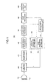
- One embodiment of the present invention will be described below with reference to FIGS. 1 to 7. FIG. 1 is a block diagram showing an ultrasound diagnostic system constructed in accordance with one embodiment of the present invention. As shown in FIG. 1, the ultrasound
diagnostic system 100 includes aprobe 110, an amplifier (AGC/LGC· and gain controller) 120, abeamformer 130, animage signal processor 140, avolume data processor 150, an imageparameter setting unit 160, abrightness adjusting unit 170, animage processor 180 and adisplay unit 190. Further, theimage signal processor 140, thevolume data processor 150, the imageparameter setting unit 160, thebrightness adjusting unit 170 and theimage processor 180 may be provided as one processor. - The
probe 110 includes a 1-dimensional or a 2-dimensional array transducer 112 including a plurality of transducer elements. The transmit signals, which are appropriately delayed in thebeamformer 130 to form an ultrasound beam, are transmitted to thearray transducer 112. Then, the focused ultrasound beam, which is produced in response to the transmit signals, is transmitted along a scan line set in a target object (not shown). Theprobe 110 receives ultrasound echo signals reflected from the target object and converts the ultrasound echo signals into electrical signals (hereinafter referred to as "receive signals"). The receive signals are transmitted to theamplifier 120. - The
amplifier 120 adjusts the gains of the receive signals in axial and lateral directions for axial gain compensation (AGC) and lateral gain compensation (LGC), respectively. This is to compensate for the loss in amplitude due to attenuation according to AGC/LGC parameters provided from the imageparameter setting unit 160. Further, theamplifier 120 amplifies the receive signals based on the gain parameter provided from the imageparameter setting unit 160. - The
beamformer 130 provides delays to transmit signals to be transmitted to thearray transducer 112 included in theprobe 110 such that the ultrasound signals outputted from thearray transducer 112 are focused on a focal point. Further, thebeamformer 120 focuses the receive signals, which are received from thearray transducer 112 included in theprobe 110, in consideration of the delays with which the echo signals are arrived at each transducer element. It then outputs a focused receive beam representing the energy level of the ultrasound echo signals reflected from the focal point. - The image signal processor 140 (e.g., a digital signal processor (DSP)) performs an envelope detection for detecting the intensities of the focused receive signals to form ultrasound image data. That is, the
image signal processor 140 forms ultrasound image data based on the receive focused signals acquired from each focal point and position information of a plurality of focal points on each scan line. The ultrasound image data include the coordinate information of each focal point, the angle information of each scan line and the intensity information of the echo signals received at each focal point. The ultrasound image data may be 2D ultrasound data. - The
volume data processor 150 forms the volume data based on the ultrasound image data formed by theimage signal processor 140. Thevolume data processor 150 sets a specified number of frames in the volume data. The frames are used for setting the AGC/LGC and gain parameters to be applied to the ultrasound image data. For example, thevolume data processor 150 forms thevolume data 210 based on the ultrasound image data (shown in FIG. 4) and then sets theframes 221 to 223 in thevolume data 210. In such a case, the number of frames may be one or more (i.e., not limited to three). - The image
parameter setting unit 160 includes an AGC/LGCparameter setting unit 161 and a gainparameter setting unit 162. The AGC/LGCparameter setting unit 161 extracts the frames, which are set in the volume data by thevolume data processor 150. Then, the AGC/LGCparameter setting unit 161 sets the optimized AGC/LGC parameters to perform AGC/LGC for the receive signals based on the characteristics of the extracted frames. That is, the AGC/LGCparameter setting unit 161 sets the optimized AGC/LGC parameters to be applied to the receive signals to compensate for the attenuation of the ultrasound echo signals in the axial and lateral directions. The function and operation of the AGC/LGCparameter setting unit 161 will be described in detail with reference to FIGS. 3 and 4. - The gain
parameter setting unit 162 sets a gain parameter for controlling the gain of the ultrasound image data based on the characteristics of the frames extracted from the volume data. That is, the gainparameter setting unit 162 sets the gain parameter for adjusting the entire gain of the 2D ultrasound images. The function and operation of the gainparameter setting unit 162 will be described in detail with reference to FIG. 5. - The
brightness adjusting unit 170 analyzes a histogram of volume data formed based on the ultrasound image data obtained by applying the optimized AGC/LGC and gain parameters to the receive signals, thereby detecting the characteristic value of pixel intensities. Then, thebrightness adjusting unit 170 sets a dynamic range (DR) parameter for adjusting the brightness of the volume data based on the detected characteristic value of the pixel intensities. The characteristic value of the pixel intensities may include a mean value, a median value, a maximum value, a minimum value, a standard deviation and a variance of the pixel intensities. The function and operation of thebrightness adjusting unit 170 will be described in detail with reference to FIGS. 6 and 7. - The
image processor 180 forms the ultrasound images based on the volume data formed by thevolume data processor 150. Theimage processor 180 includes a 2D image processor and a 3D image processor (not shown). The 2D image processor forms the 2D ultrasound images based on the frames set in the volume data by thevolume data processor 150, wherein the planes were obtained by applying the optimized AGC/LGC and gain parameters to the receive signals. The 3D image processor forms a 3D ultrasound image based on the volume data, the brightness of which has been adjusted by thebrightness adjusting unit 170. The ultrasound images provided from theimage processor 180 are displayed in thedisplay unit 190. - Hereinafter, a process of adjusting the brightness of ultrasound images will be described in detail with reference to FIGS. 2 to 7. FIG. 2 is a flowchart showing a process of processing an ultrasound image in accordance with one embodiment of the present invention.
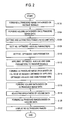
- As shown in FIG. 2, the
image signal processor 140 forms the ultrasound image data based on the receive signals received from theprobe 110 at step S102. Thevolume data processor 150 forms the volume data based on the ultrasound image data at step S104. The volume data processor sets a specified number of frames in the volume data and then extracts the frames set in the volume data at step S106. - The AGC/LGC
parameter setting unit 161 sets optimized AGC/LGC parameters based on the characteristics of the extracted frames at step S108. The step S108 will be described in detail with reference to FIGS. 3 and 4. The gainparameter setting unit 162 sets an optimized gain parameter based on the characteristics of the extracted frames at step S110. The step S110 will be described in detail with reference to FIG. 5. - The
amplifier 120 performs AGC/LGC upon the receive signals based on the optimized AGC/LGC parameters and then amplifies the receive signals based on the optimized gain parameter at step S112. Theimage signal processor 140 forms the ultrasound image data based on the receive signals obtained by applying the optimized AGC/LGC and gain parameters thereto at step S114. Thevolume data processor 150 forms the volume data based on the ultrasound image data at step S116. - The
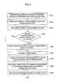
brightness adjusting unit 170 adjusts the brightness of the volume data at step S118. The step S118 will be described in detail with reference to FIG. 6. Theimage processor 180 forms the ultrasound images (i.e., 2D and 3D ultrasound images). The formed ultrasound images are displayed in thedisplay unit 190 at step S122. - Hereinafter, a process of setting AGC/LGC parameters will be described with reference to FIGS. 3 and 4. FIG. 3 is a flowchart showing a process of setting AGC/LGC parameters in accordance with one embodiment of the present invention. FIG. 4 is an exemplary diagram showing the volume data and frames set in the volume data in accordance with one embodiment of the present invention.
- The AGC/LGC
parameter setting unit 161 segments theframes 221 to 223 extracted from thevolume data 210 into a plurality of regions, respectively, at step S210. In order to set the AGC parameter, theframes 221 to 223 are segmented in a vertical direction of theframes 221 to 223 displayed in thedisplay unit 190. Further, in order to set the LCG parameter, theframes 221 to 223 are segmented in a horizontal direction of theframes 221 to 223 displayed in thedisplay unit 190. The AGC/LGCparameter setting unit 161 detects the pixels at the same depth from each vertically-segmented region for setting an AGC parameter at step S220. Also, the AGC/LGCparameter setting unit 161 detects the pixels at the same scanline from each horizontally-segmented region for setting an LGC parameter (step S230). - The AGC/LGC
parameter setting unit 161 computes the intensity characteristic values of the detected pixels at step S240. The intensity characteristic values may include a mean value, a median value, a maximum value, a minimum value, a standard deviation, a variance and the like of the detected pixel intensities. Then, the AGC/LGCparameter setting unit 161 obtains the profiles of the pixel intensities for respective regions based on the intensity characteristic values at step S250. The profiles include the vertical profiles for the AGC parameter and the horizontal profiles for the LGC parameter. - The AGC/LGC
parameter setting unit 161 models the profiles in a straight line at step S260. Such modeling may be carried out by using a Least Squares Fit method. The AGC/LGCparameter setting unit 161 selects a specified number of profiles with a relatively gentle gradient by analyzing the gradients of the modeled profiles at step S270. The gradient of the modeled profile represents the brightness attenuation of the ultrasound image in a depth direction or a lateral direction. For example, the gradient of the profile is relatively steep in a dark region of the ultrasound image. Further, the gradient of the modeled horizontal profile represents the brightness of the pixels at the same depth in the ultrasound image. When the ultrasound image shows a heart in a lateral direction, there is a tendency that a central portion is bright and both end portions are dark. Therefore, the AGC/LGCparameter setting unit 161 selects a specified number of profiles with a gentle gradient in consideration of such characteristics. - The AGC/LGC
parameter setting unit 161 forms representative vertical and horizontal profiles showing the brightness attenuation of the extracted frames based on the selected profiles at step S280. Specifically, the AGC/LGCparameter setting unit 161 calculates the mean gradient of the selected profiles, respectively, and sets the profiles having the mean gradient as representative profiles. Finally, the AGC/LGCparameter setting unit 161 sets the AGC/LGC parameters based on the representative profiles at step S290. - Hereinafter, a process of setting a gain parameter in accordance with one embodiment of the present invention will be described in detail with reference to FIG. 5. FIG. 5 is a flowchart showing a process of setting a gain parameter in accordance with the embodiment of the present invention. As shown in FIG. 5, the
gain processor 162 segments the extracted frames into multiple blocks in horizontal and vertical directions at step S310. It then computes the mean brightness of the pixels within each block, which represents the brightness characteristic of each block at step S320. Also, the median value, maximum value, minimum value, standard deviation and variance of brightness of pixels within each block may be computed instead of the mean brightness for representing the brightness characteristic of each block. - The gain
parameter setting unit 162 analyzes the computed mean brightness at each block at step S330 and checks whether at least one block corresponding to outlier exists in the segmented blocks at step S340. If an arbitrary block has a mean brightness greater than a threshold, then the block is considered as the outlier representing a noise block. If it is determined that the block corresponding to the outlier exists in the segmented blocks at step S340, then the gainparameter setting unit 162 removes the block corresponding to the outlier at step S350. - Then, the gain
parameter setting unit 162 defines a brightness range of the residual blocks except the removed block as a brightness range of typical soft tissues. On the other hand, if it is determined that there is no block corresponding to the outlier at step S340, then the gainparameter setting unit 162 defines a bright range of all blocks as a brightness range of typical soft tissues at step S360. - The gain
parameter setting unit 162 computes the mean brightness of the entire blocks within the brightness range of the typical soft tissues at step S370. The gainparameter setting unit 162 compares the computed means brightness with a reference mean brightness, which is previously set and stored at step S380. Finally, the gainparameter setting unit 162 sets an optimized gain parameter based on the comparison result at step S390. - Hereinafter, a process of adjusting the brightness of volume data in accordance with one embodiment of the present invention will be described in detail with reference to FIGS. 6 and 7. FIG. 6 is a flowchart showing a process of adjusting the brightness of volume data in accordance with one embodiment of the present invention. FIG. 7 illustrates a brightness adjustment function in accordance with one embodiment of the present invention.
- As shown in FIG. 6, the
brightness adjusting unit 170 analyzes a histogram of the volume data at step S410. Also, in accordance with another embodiment of the present invention, thebrightness adjusting unit 170 may analyze a histogram of a frame extracted from the volume data instead of analyzing the histogram of the volume data for reducing an analysis time. - The
brightness adjusting unit 170 analyzes the histogram of the volume data, thereby obtaining the intensity characteristic values at step S420. Specially, thebrightness adjusting unit 170 obtains the maximum intensity of pixels in the volume data as an intensity characteristic value. As shown in FIG. 7, thebrightness adjusting unit 170 obtains abrightness adjustment function 310 for adjusting the brightness of the volume data based on the maximum intensity of the pixels at step S430. Thebrightness adjustment function 310 may be defined as the following equation (1): -

- wherein Input represents the intensities of pixels included in the input volume data, max intensity represents the maximum intensity of pixels in the volume data, and ideal max intensity represents the maximum intensity of pixels in the volume data obtained by applying optimized image parameters. The ideal max intensity is previously calculated and stored in accordance with the present invention. The
brightness adjusting unit 170 adjusts the brightness of the volume data based on thebrightness adjustment function 310 at step S440. - In accordance with the present invention, since the AGC/LGC and gain parameters are set based on the frames extracted from the volume data, the image quality of the 3-dimensional ultrasound image can be substantially improved. Also, the brightness of the volume data is adjusted in accordance with the present invention and the brightness of the 3D ultrasound image can be adjusted more accurately. Thus, the user can make a diagnosis more accurately and easily.
- An embodiment may be achieved in whole or in part by an image processing system, which includes: a volume data processor for forming volume data based on image signals and setting at least one frame in the volume data; an AGC/LGC parameter setting unit for setting axial gain compensation (AGC) and lateral gain compensation (LGC) parameters based on the frame; a gain parameter setting unit for setting a gain parameter based on the frame; an amplifying unit for performing AGC/LGC upon image signals based on the AGC/LGC parameters and amplifying the image signals based on the gain parameter to provide amplified image signals; a brightness adjusting unit for analyzing intensities of pixels included in the volume data formed based on the amplified image signals and based thereupon, adjusting brightness of the volume data based on the analysis result; and an image processor for forming images based on the frame and the brightness-adjusted volume data.
- In accordance with another embodiment of the present invention, there is provided an image processing method, comprising: a) forming volume data based on image signals; b) setting at least one frame in the volume data and extracting the frame; c) setting axial gain compensation (AGC) and lateral gain compensation (LGC) parameters based on the extracted frame; d) setting a gain parameter based on the extracted frame; e) performing AGC/LGC upon image signals based on the AGC/LGC parameters and amplifying the image signals based on the gain parameter to provide amplified image signals; f) forming volume data based on the amplified image signal; g) computing an intensity characteristic value of the volume data and adjusting brightness of the volume data based on the computed intensity characteristic value; and h) forming images based on the frame and the brightness-adjusted volume data.
- Any reference in this specification to "one embodiment," "an embodiment," "example embodiment," etc. means that a particular feature, structure or characteristic described in connection with the embodiment is included in at least one embodiment of the invention. The appearances of such phrases in various places in the specification are not necessarily all referring to the same embodiment. Further, when a particular feature, structure or characteristic is described in connection with any embodiment, it falls within the purview of one skilled in the art to effectuate such a feature, structure or characteristic in connection with other ones of the embodiments.
- Although embodiments have been described with reference to a number of illustrative embodiments thereof, it should be understood that various other modifications and embodiments can be devised by those skilled in the art that will fall within the spirit and scope of the principles of this disclosure. More particularly, numerous variations and modifications are possible in the component parts and/or arrangements of the subject combination arrangement within the scope of the disclosure, drawings and appended claims. In addition to such variations and modifications in the component parts and/or arrangements, alternative uses will also be apparent to those skilled in the art.
Claims (18)
- An image processing system, comprising:a volume data processor for forming volume data based on image signals and setting at least one frame in the volume data;an AGC/LGC parameter setting unit for setting axial gain compensation (AGC) and lateral gain compensation (LGC) parameters based on the frame;a gain parameter setting unit for setting a gain parameter based on the frame;an amplifying unit for performing AGC/LGC upon image signals based on the AGC/LGC parameters and amplifying the image signals based on the gain parameter to provide amplified image signals;a brightness adjusting unit for analyzing intensities of pixels included in the volume data formed based on the amplified image signals and based thereupon, adjusting brightness of the volume data based on the analysis result; andan image processor for forming images based on the frame and the brightness-adjusted volume data.
- The image processing system of Claim 1, wherein the image signals are ultrasound image signals.
- The image processing system of Claim 1, wherein the AGC/LGC parameter setting unit operates to:segment the frame set in the volume data into a plurality of regions in a specified direction;compute intensity characteristic values of pixels at the same depth detected from each region;obtain vertical profiles of the intensity characteristic values in each region and modeling the vertical profiles in a straight line;select a predetermined number of vertical profiles having a relatively gentle gradient;form a representative profile based on the selected vertical profiles; andset the AGC parameter based on the representative profile.
- The image processing system of Claim 3, wherein the AGC/LGC parameter setting unit forms the representative profile to have a mean gradient of the selected vertical profiles.
- The image processing system of Claim 1, wherein the AGC/LGC parameter setting unit operates to:segment the frame set in the volume data into a plurality of regions in a specified direction;compute intensity characteristic values of pixels at the same scanline detected from each region;obtain horizontal profiles of the intensity characteristic values in each region and modeling the horizontal profiles in a straight line;select a predetermined number of horizontal profiles having a relatively gentle gradient;form a representative profile based on the selected horizontal profiles; andset the LGC parameter based on the representative curve.
- The image processing system of Claim 5, wherein the AGC/LGC parameter setting unit forms the representative profile to have a mean gradient of the selected horizontal profiles.
- The image processing system of Claim 1, wherein the gain parameter setting unit operates to:segment the frame into multiple blocks in horizontal and vertical directions and computing mean brightness of pixels in each block;remove blocks having the mean brightness greater than a threshold and defining a brightness range of residual blocks as a brightness range of a target object;compute a mean value of the mean brightness of each block;compare the mean value with a reference value; andset the gain parameter based on the comparison result.
- The image processing system of Claim 1, wherein the brightness adjusting unit operates to:analyze a histogram of the volume data to obtain an intensity characteristic value of the volume data;compare the intensity characteristic value with a reference value;obtain a brightness adjustment function based on the comparison result; andadjust brightness of the volume data based on the brightness adjustment function.
- The image processing system of Claim 1, wherein the image processor forms a 2D image based on the frame and a 3D image based on the volume data.
- A method of processing an image , comprising:a) forming volume data based on image signals;b) setting at least one frame in the volume data and extracting the frame;c) setting axial gain compensation (AGC) and lateral gain compensation (LGC) parameters based on the extracted frame;d) setting a gain parameter based on the extracted frame;e) performing AGC/LGC upon image signals based on the AGC/LGC parameters and amplifying the image signals based on the gain parameter to provided amplified image signals;f) forming volume data based on the amplified image signal;g) computing an intensity characteristic value of the volume data and adjusting brightness of the volume data based on the computed intensity characteristic value; andh) forming images based on the frame and the brightness-adjusted volume data.
- The method of Claim 10, wherein the image signals are ultrasound image signals.
- The method of Claim 10, wherein the step c) includes:c11) segmenting the frame set in the volume data into a plurality of regions in a specified direction;c12) computing intensity characteristic values of pixels at the same depth detected from each region;c13) obtaining vertical profiles of the intensity characteristic values in each region and modeling the vertical profiles in a straight line;c14) selecting a predetermined number of vertical profiles having a relatively gentle gradient;c15) forming a representative profile based on the selected vertical profiles; andc16) setting the AGC parameter based on the representative profile.
- The method of Claim 12, wherein the step c15) includes:computing a mean gradient value of the selected vertical profiles;forming the representative profile having the mean gradient.
- The method of Claim 10, wherein the step c) includes:c21) segmenting the frame set in the volume data into a plurality of regions in a specified direction;c22) computing intensity characteristic values of pixels at the same scanline detected from each region;c23) obtaining horizontal profiles of the intensity characteristic values in each region and modeling the horizontal profiles in a straight line;c24) selecting a predetermined number of horizontal profiles having a relatively gentle gradient;c25) forming a representative profile based on the selected horizontal profiles; andc26) setting the LGC parameter based on the representative curve.
- The method of Claim 14, wherein the step c25) includes:computing a mean gradient value of the selected horizontal profiles;forming the representative profile having the mean gradient.
- The method of Claim 10, wherein the step d) includes:d1) segmenting the frame into multiple blocks in horizontal and vertical directions and computing mean brightness of pixels in each block;d2) removing blocks having the mean brightness greater than a threshold and defining a brightness range of residual blocks as a brightness range of a target object;d3) computing a mean value of the mean brightness of each block;d4) comparing the mean value with a reference value; andd5) setting the gain parameter based on the comparison result.
- The method of Claim 10, wherein the step g) includes:g1) analyzing a histogram of the volume data to obtain an intensity characteristic value of the volume data;g2) comparing the intensity characteristic value with a reference value;g3) obtaining a brightness adjustment function based on the comparison result; andg4) adjusting brightness of the volume data based on the brightness adjustment function.
- The method of Claim 10, wherein the step h) includes:h1) forming a 2D image based on the frame; andh2) forming a 3D image based on the volume data.
Applications Claiming Priority (1)
| Application Number | Priority Date | Filing Date | Title |
|---|---|---|---|
| KR1020060022504A KR100908252B1 (en) | 2006-03-10 | 2006-03-10 | Image Processing System and Method |
Publications (3)
| Publication Number | Publication Date |
|---|---|
| EP1832894A2 true EP1832894A2 (en) | 2007-09-12 |
| EP1832894A3 EP1832894A3 (en) | 2013-02-20 |
| EP1832894B1 EP1832894B1 (en) | 2017-05-10 |
Family
ID=38123767
Family Applications (1)
| Application Number | Title | Priority Date | Filing Date |
|---|---|---|---|
| EP07004722.0A Active EP1832894B1 (en) | 2006-03-10 | 2007-03-07 | System and method for automatic gain compensation based on image processing |
Country Status (4)
| Country | Link |
|---|---|
| US (1) | US7787680B2 (en) |
| EP (1) | EP1832894B1 (en) |
| JP (1) | JP5040377B2 (en) |
| KR (1) | KR100908252B1 (en) |
Cited By (1)
| Publication number | Priority date | Publication date | Assignee | Title |
|---|---|---|---|---|
| US20180260990A1 (en) * | 2017-03-07 | 2018-09-13 | Thomas Brunner | Method and Apparatus for Generating an Output Image from a Volume Data Set |
Families Citing this family (41)
| Publication number | Priority date | Publication date | Assignee | Title |
|---|---|---|---|---|
| US8105239B2 (en) * | 2006-02-06 | 2012-01-31 | Maui Imaging, Inc. | Method and apparatus to visualize the coronary arteries using ultrasound |
| EP2048512A3 (en) * | 2006-03-31 | 2009-12-09 | Aloka Co. Ltd. | Methods and apparatus for ultrasound imaging |
| JP4945273B2 (en) * | 2006-04-24 | 2012-06-06 | 株式会社東芝 | Ultrasonic diagnostic apparatus and control program for ultrasonic diagnostic apparatus |
| US9146313B2 (en) | 2006-09-14 | 2015-09-29 | Maui Imaging, Inc. | Point source transmission and speed-of-sound correction using multi-aperature ultrasound imaging |
| WO2008051639A2 (en) | 2006-10-25 | 2008-05-02 | Maui Imaging, Inc. | Method and apparatus to produce ultrasonic images using multiple apertures |
| KR101028354B1 (en) * | 2007-03-20 | 2011-06-14 | 주식회사 메디슨 | Ultrasound system and method for forming ultrasound image |
| US9282945B2 (en) | 2009-04-14 | 2016-03-15 | Maui Imaging, Inc. | Calibration of ultrasound probes |
| US9247926B2 (en) | 2010-04-14 | 2016-02-02 | Maui Imaging, Inc. | Concave ultrasound transducers and 3D arrays |
| US9788813B2 (en) | 2010-10-13 | 2017-10-17 | Maui Imaging, Inc. | Multiple aperture probe internal apparatus and cable assemblies |
| JP5666446B2 (en) | 2008-08-08 | 2015-02-12 | マウイ イマギング,インコーポレーテッド | Image forming method using multi-aperture medical ultrasonic technology and synchronization method of add-on system |
| JP5248961B2 (en) * | 2008-09-18 | 2013-07-31 | パナソニック株式会社 | Ultrasonic diagnostic equipment |
| KR100989580B1 (en) * | 2008-09-30 | 2010-10-25 | 주식회사 바이오넷 | Diplay Calibration Method for Ultrasonic Aparratus |
| WO2010120907A2 (en) | 2009-04-14 | 2010-10-21 | Maui Imaging, Inc. | Multiple aperture ultrasound array alignment fixture |
| US9289191B2 (en) | 2011-10-12 | 2016-03-22 | Seno Medical Instruments, Inc. | System and method for acquiring optoacoustic data and producing parametric maps thereof |
| US8744793B2 (en) | 2010-10-20 | 2014-06-03 | Sonix, Inc. | Method and apparatus for adjusting the level of a response signal from an ultrasound transducer |
| KR101422574B1 (en) * | 2010-11-25 | 2014-07-24 | 서강대학교산학협력단 | Ultrasonic diagnostic apparatus and control method thereof |
| US11287309B2 (en) | 2011-11-02 | 2022-03-29 | Seno Medical Instruments, Inc. | Optoacoustic component utilization tracking |
| US9730587B2 (en) | 2011-11-02 | 2017-08-15 | Seno Medical Instruments, Inc. | Diagnostic simulator |
| US11191435B2 (en) | 2013-01-22 | 2021-12-07 | Seno Medical Instruments, Inc. | Probe with optoacoustic isolator |
| US9814394B2 (en) | 2011-11-02 | 2017-11-14 | Seno Medical Instruments, Inc. | Noise suppression in an optoacoustic system |
| US9733119B2 (en) | 2011-11-02 | 2017-08-15 | Seno Medical Instruments, Inc. | Optoacoustic component utilization tracking |
| US9743839B2 (en) | 2011-11-02 | 2017-08-29 | Seno Medical Instruments, Inc. | Playback mode in an optoacoustic imaging system |
| JP6407719B2 (en) | 2011-12-01 | 2018-10-17 | マウイ イマギング,インコーポレーテッド | Motion detection using ping base and multi-aperture Doppler ultrasound |
| US9265484B2 (en) | 2011-12-29 | 2016-02-23 | Maui Imaging, Inc. | M-mode ultrasound imaging of arbitrary paths |
| JP6438769B2 (en) | 2012-02-21 | 2018-12-19 | マウイ イマギング,インコーポレーテッド | Determination of material hardness using multiple aperture ultrasound. |
| SG11201405548RA (en) | 2012-03-09 | 2014-10-30 | Seno Medical Instr Inc | Statistical mapping in an optoacoustic imaging system |
| CN104203110B (en) | 2012-03-26 | 2017-06-06 | 毛伊图像公司 | System and method for improving ultrasonoscopy quality by the application weighting factor |
| KR102176193B1 (en) | 2012-08-10 | 2020-11-09 | 마우이 이미징, 인코포레이티드 | Calibration of Multiple Aperture Ultrasound Probes |
| KR102176319B1 (en) | 2012-08-21 | 2020-11-09 | 마우이 이미징, 인코포레이티드 | Ultrasound imaging system memory architecture |
| US9510806B2 (en) | 2013-03-13 | 2016-12-06 | Maui Imaging, Inc. | Alignment of ultrasound transducer arrays and multiple aperture probe assembly |
| US9883848B2 (en) | 2013-09-13 | 2018-02-06 | Maui Imaging, Inc. | Ultrasound imaging using apparent point-source transmit transducer |
| KR102249528B1 (en) | 2014-04-01 | 2021-05-11 | 삼성메디슨 주식회사 | Method, apparatus and system for adjusting brightness of ultrasound image by using prestored gradation data set and images |
| JP6722656B2 (en) | 2014-08-18 | 2020-07-15 | マウイ イマギング,インコーポレーテッド | Network-based ultrasound imaging system |
| US20160157827A1 (en) * | 2014-12-03 | 2016-06-09 | General Electric Company | Methods and systems for ultrasound imaging |
| KR101652723B1 (en) * | 2015-04-10 | 2016-08-31 | 서강대학교산학협력단 | Ultrasonic image quality improving method and ultrasonic imaging apparatus using the same |
| KR101685823B1 (en) * | 2015-06-18 | 2016-12-21 | 인하대학교 산학협력단 | Method and System for Visual Quality Enhancement for Chest X-ray Images |
| US10996333B2 (en) * | 2015-11-02 | 2021-05-04 | Koninklijke Philips N.V. | Ultrasound system for providing ultrasound images at variable frequencies of a volumetric region comprising an interferer analyzer |
| WO2017132517A1 (en) | 2016-01-27 | 2017-08-03 | Maui Imaging, Inc. | Ultrasound imaging with sparse array probes |
| WO2018023082A1 (en) * | 2016-07-28 | 2018-02-01 | Easy Life Brands LLC | Automatic flame extinguisher |
| CN106618632B (en) * | 2016-12-14 | 2020-08-07 | 无锡祥生医疗科技股份有限公司 | Automatic optimized ultrasonic imaging system and method |
| KR102296675B1 (en) * | 2018-02-09 | 2021-09-02 | 지멘스 메디컬 솔루션즈 유에스에이, 인크. | Method and ultrasound system for generating compounding image |
Citations (3)
| Publication number | Priority date | Publication date | Assignee | Title |
|---|---|---|---|---|
| US5524626A (en) | 1995-06-30 | 1996-06-11 | Siemens Medical Systems, Inc. | System and method for determining local attenuation for ultrasonic imaging |
| EP1005833A1 (en) | 1998-12-01 | 2000-06-07 | General Electric Company | Method and apparatus for automatic time and/or lateral gain compensation in B-mode ultrasound imaging |
| US20030028107A1 (en) | 2001-07-31 | 2003-02-06 | Miller David G. | Transesophageal and transnasal, transesophageal ultrasound imaging systems |
Family Cites Families (16)
| Publication number | Priority date | Publication date | Assignee | Title |
|---|---|---|---|---|
| US4733668A (en) * | 1979-09-04 | 1988-03-29 | North American Philips Corporation | Method and apparatus for compensation during ultrasound examination |
| JPS58183151A (en) * | 1982-04-21 | 1983-10-26 | 株式会社東芝 | Ultrasonic diagnostic apparatus |
| US5257624A (en) * | 1991-10-25 | 1993-11-02 | Hewlett-Packard Company | Gain control for ultrasound system |
| US5313948A (en) * | 1991-11-28 | 1994-05-24 | Aloka Co., Ltd. | Ultrasonic diagnostic apparatus |
| JP3245225B2 (en) * | 1992-08-10 | 2002-01-07 | フクダ電子株式会社 | Ultrasound diagnostic equipment |
| JPH06133967A (en) | 1992-10-29 | 1994-05-17 | Olympus Optical Co Ltd | Ultrasonic diagnostic system |
| JP3610129B2 (en) * | 1995-09-18 | 2005-01-12 | ジーイー横河メディカルシステム株式会社 | Image display method and apparatus, and ultrasonic diagnostic apparatus |
| JPH10234726A (en) * | 1997-02-26 | 1998-09-08 | Shimadzu Corp | Ultrasonic diagnosis device |
| US6224552B1 (en) * | 1998-10-01 | 2001-05-01 | Atl Ultrasound | Ultrasonic diagnostic imaging system with reduced spatial compounding seam artifacts |
| JP2000139914A (en) * | 1998-11-04 | 2000-05-23 | Aloka Co Ltd | Ultrasonograph |
| US6666824B2 (en) * | 2002-04-01 | 2003-12-23 | Koninklijke Philips Electronics N.V. | System and method of dynamic automatic sensing of available dynamic range |
| US6743174B2 (en) * | 2002-04-01 | 2004-06-01 | Koninklijke Philips Electronics N.V. | Ultrasonic diagnostic imaging system with automatically controlled contrast and brightness |
| US6679844B2 (en) * | 2002-06-20 | 2004-01-20 | Acuson Corporation | Automatic gain compensation for multiple mode or contrast agent imaging |
| JP4482289B2 (en) * | 2003-06-09 | 2010-06-16 | ジーイー・メディカル・システムズ・グローバル・テクノロジー・カンパニー・エルエルシー | Flow image display method and ultrasonic diagnostic apparatus |
| JP2006020777A (en) * | 2004-07-07 | 2006-01-26 | Aloka Co Ltd | Ultrasonic diagnostic apparatus |
| US7645236B2 (en) * | 2005-06-28 | 2010-01-12 | Siemens Medical Solutions Usa, Inc. | Ultrasound imaging system having motion adaptive gain |
-
2006
- 2006-03-10 KR KR1020060022504A patent/KR100908252B1/en active IP Right Grant
-
2007
- 2007-03-07 EP EP07004722.0A patent/EP1832894B1/en active Active
- 2007-03-09 US US11/684,234 patent/US7787680B2/en active Active
- 2007-03-09 JP JP2007060265A patent/JP5040377B2/en not_active Expired - Fee Related
Patent Citations (3)
| Publication number | Priority date | Publication date | Assignee | Title |
|---|---|---|---|---|
| US5524626A (en) | 1995-06-30 | 1996-06-11 | Siemens Medical Systems, Inc. | System and method for determining local attenuation for ultrasonic imaging |
| EP1005833A1 (en) | 1998-12-01 | 2000-06-07 | General Electric Company | Method and apparatus for automatic time and/or lateral gain compensation in B-mode ultrasound imaging |
| US20030028107A1 (en) | 2001-07-31 | 2003-02-06 | Miller David G. | Transesophageal and transnasal, transesophageal ultrasound imaging systems |
Cited By (1)
| Publication number | Priority date | Publication date | Assignee | Title |
|---|---|---|---|---|
| US20180260990A1 (en) * | 2017-03-07 | 2018-09-13 | Thomas Brunner | Method and Apparatus for Generating an Output Image from a Volume Data Set |
Also Published As
| Publication number | Publication date |
|---|---|
| JP5040377B2 (en) | 2012-10-03 |
| US20070236492A1 (en) | 2007-10-11 |
| JP2007236955A (en) | 2007-09-20 |
| KR20070092407A (en) | 2007-09-13 |
| EP1832894B1 (en) | 2017-05-10 |
| KR100908252B1 (en) | 2009-07-20 |
| EP1832894A3 (en) | 2013-02-20 |
| US7787680B2 (en) | 2010-08-31 |
Similar Documents
| Publication | Publication Date | Title |
|---|---|---|
| EP1832894A2 (en) | System and method for automatic gain compensation based on image processing | |
| EP1793343B1 (en) | Image processing system and method of enhancing the quality of an ultrasound image | |
| US9901323B2 (en) | Aberration correction using channel data in ultrasound imaging system | |
| US8684934B2 (en) | Adaptively performing clutter filtering in an ultrasound system | |
| JP4585326B2 (en) | Ultrasonic imaging apparatus and ultrasonic imaging method | |
| US20060079780A1 (en) | Ultrasonic imaging apparatus | |
| KR101422574B1 (en) | Ultrasonic diagnostic apparatus and control method thereof | |
| JP4996247B2 (en) | Ultrasonic diagnostic equipment | |
| JP2004215987A (en) | Ultrasonic diagnosing equipment and ultrasonic diagnosing method | |
| US7738685B2 (en) | Image processing system and method for controlling gains for color flow images | |
| US20150359507A1 (en) | Ultrasound diagnosis apparatus and ultrasound image processing method | |
| JP2005152648A (en) | Method and system for motion-adaptive type spatial synthesis | |
| KR100873336B1 (en) | Ultrasound diagnostic system and method for automatically controlling brightness and contrast of a three-dimensional ultrasound image | |
| JP5467783B2 (en) | Ultrasonic system and clutter signal filtering method | |
| KR101652728B1 (en) | Ultrasonic image quality improving method and ultrasonic imaging apparatus using the same | |
| JP4664209B2 (en) | Ultrasonic diagnostic apparatus and ultrasonic imaging program for performing imaging thereof | |
| JP2815622B2 (en) | Ultrasound diagnostic equipment | |
| KR101542807B1 (en) | Image Quality Improving Method and Ultrasonic Imaging Apparatus using the same | |
| JP2021083956A (en) | Ultrasonic diagnostic apparatus |
Legal Events
| Date | Code | Title | Description |
|---|---|---|---|
| PUAI | Public reference made under article 153(3) epc to a published international application that has entered the european phase |
Free format text: ORIGINAL CODE: 0009012 |
|
| AK | Designated contracting states |
Kind code of ref document: A2 Designated state(s): AT BE BG CH CY CZ DE DK EE ES FI FR GB GR HU IE IS IT LI LT LU LV MC MT NL PL PT RO SE SI SK TR |
|
| AX | Request for extension of the european patent |
Extension state: AL BA HR MK YU |
|
| PUAL | Search report despatched |
Free format text: ORIGINAL CODE: 0009013 |
|
| AK | Designated contracting states |
Kind code of ref document: A3 Designated state(s): AT BE BG CH CY CZ DE DK EE ES FI FR GB GR HU IE IS IT LI LT LU LV MC MT NL PL PT RO SE SI SK TR |
|
| AX | Request for extension of the european patent |
Extension state: AL BA HR MK RS |
|
| RIC1 | Information provided on ipc code assigned before grant |
Ipc: G01S 15/89 20060101ALN20130115BHEP Ipc: G01S 7/52 20060101AFI20130115BHEP |
|
| 17P | Request for examination filed |
Effective date: 20130730 |
|
| RBV | Designated contracting states (corrected) |
Designated state(s): AT BE BG CH CY CZ DE DK EE ES FI FR GB GR HU IE IS IT LI LT LU LV MC MT NL PL PT RO SE SI SK TR |
|
| AKX | Designation fees paid |
Designated state(s): AT BE BG CH CY LI |
|
| REG | Reference to a national code |
Ref country code: DE Ref legal event code: R108 |
|
| RBV | Designated contracting states (corrected) |
Designated state(s): AT BE BG CH CY CZ DE DK EE ES FI FR GB GR HU IE IS IT LI LT LU LV MC MT NL PL PT RO SE SI SK TR |
|
| GRAP | Despatch of communication of intention to grant a patent |
Free format text: ORIGINAL CODE: EPIDOSNIGR1 |
|
| RIC1 | Information provided on ipc code assigned before grant |
Ipc: G01S 15/89 20060101ALN20161110BHEP Ipc: G01S 7/52 20060101AFI20161110BHEP |
|
| RIC1 | Information provided on ipc code assigned before grant |
Ipc: G01S 15/89 20060101ALN20161124BHEP Ipc: G01S 7/52 20060101AFI20161124BHEP |
|
| INTG | Intention to grant announced |
Effective date: 20161208 |
|
| GRAS | Grant fee paid |
Free format text: ORIGINAL CODE: EPIDOSNIGR3 |
|
| RAP1 | Party data changed (applicant data changed or rights of an application transferred) |
Owner name: SAMSUNG MEDISON CO., LTD. |
|
| GRAA | (expected) grant |
Free format text: ORIGINAL CODE: 0009210 |
|
| AK | Designated contracting states |
Kind code of ref document: B1 Designated state(s): AT BE BG CH CY CZ DE DK EE ES FI FR GB GR HU IE IS IT LI LT LU LV MC MT NL PL PT RO SE SI SK TR |
|
| REG | Reference to a national code |
Ref country code: GB Ref legal event code: FG4D |
|
| REG | Reference to a national code |
Ref country code: AT Ref legal event code: REF Ref document number: 892918 Country of ref document: AT Kind code of ref document: T Effective date: 20170515 Ref country code: CH Ref legal event code: EP |
|
| REG | Reference to a national code |
Ref country code: IE Ref legal event code: FG4D |
|
| REG | Reference to a national code |
Ref country code: DE Ref legal event code: R096 Ref document number: 602007050901 Country of ref document: DE |
|
| REG | Reference to a national code |
Ref country code: NL Ref legal event code: FP |
|
| REG | Reference to a national code |
Ref country code: LT Ref legal event code: MG4D |
|
| REG | Reference to a national code |
Ref country code: AT Ref legal event code: MK05 Ref document number: 892918 Country of ref document: AT Kind code of ref document: T Effective date: 20170510 |
|
| PG25 | Lapsed in a contracting state [announced via postgrant information from national office to epo] |
Ref country code: ES Free format text: LAPSE BECAUSE OF FAILURE TO SUBMIT A TRANSLATION OF THE DESCRIPTION OR TO PAY THE FEE WITHIN THE PRESCRIBED TIME-LIMIT Effective date: 20170510 Ref country code: LT Free format text: LAPSE BECAUSE OF FAILURE TO SUBMIT A TRANSLATION OF THE DESCRIPTION OR TO PAY THE FEE WITHIN THE PRESCRIBED TIME-LIMIT Effective date: 20170510 Ref country code: AT Free format text: LAPSE BECAUSE OF FAILURE TO SUBMIT A TRANSLATION OF THE DESCRIPTION OR TO PAY THE FEE WITHIN THE PRESCRIBED TIME-LIMIT Effective date: 20170510 Ref country code: FI Free format text: LAPSE BECAUSE OF FAILURE TO SUBMIT A TRANSLATION OF THE DESCRIPTION OR TO PAY THE FEE WITHIN THE PRESCRIBED TIME-LIMIT Effective date: 20170510 Ref country code: GR Free format text: LAPSE BECAUSE OF FAILURE TO SUBMIT A TRANSLATION OF THE DESCRIPTION OR TO PAY THE FEE WITHIN THE PRESCRIBED TIME-LIMIT Effective date: 20170811 |
|
| PG25 | Lapsed in a contracting state [announced via postgrant information from national office to epo] |
Ref country code: BG Free format text: LAPSE BECAUSE OF FAILURE TO SUBMIT A TRANSLATION OF THE DESCRIPTION OR TO PAY THE FEE WITHIN THE PRESCRIBED TIME-LIMIT Effective date: 20170810 Ref country code: LV Free format text: LAPSE BECAUSE OF FAILURE TO SUBMIT A TRANSLATION OF THE DESCRIPTION OR TO PAY THE FEE WITHIN THE PRESCRIBED TIME-LIMIT Effective date: 20170510 Ref country code: PL Free format text: LAPSE BECAUSE OF FAILURE TO SUBMIT A TRANSLATION OF THE DESCRIPTION OR TO PAY THE FEE WITHIN THE PRESCRIBED TIME-LIMIT Effective date: 20170510 Ref country code: IS Free format text: LAPSE BECAUSE OF FAILURE TO SUBMIT A TRANSLATION OF THE DESCRIPTION OR TO PAY THE FEE WITHIN THE PRESCRIBED TIME-LIMIT Effective date: 20170910 Ref country code: SE Free format text: LAPSE BECAUSE OF FAILURE TO SUBMIT A TRANSLATION OF THE DESCRIPTION OR TO PAY THE FEE WITHIN THE PRESCRIBED TIME-LIMIT Effective date: 20170510 |
|
| PG25 | Lapsed in a contracting state [announced via postgrant information from national office to epo] |
Ref country code: CZ Free format text: LAPSE BECAUSE OF FAILURE TO SUBMIT A TRANSLATION OF THE DESCRIPTION OR TO PAY THE FEE WITHIN THE PRESCRIBED TIME-LIMIT Effective date: 20170510 Ref country code: DK Free format text: LAPSE BECAUSE OF FAILURE TO SUBMIT A TRANSLATION OF THE DESCRIPTION OR TO PAY THE FEE WITHIN THE PRESCRIBED TIME-LIMIT Effective date: 20170510 Ref country code: EE Free format text: LAPSE BECAUSE OF FAILURE TO SUBMIT A TRANSLATION OF THE DESCRIPTION OR TO PAY THE FEE WITHIN THE PRESCRIBED TIME-LIMIT Effective date: 20170510 Ref country code: SK Free format text: LAPSE BECAUSE OF FAILURE TO SUBMIT A TRANSLATION OF THE DESCRIPTION OR TO PAY THE FEE WITHIN THE PRESCRIBED TIME-LIMIT Effective date: 20170510 Ref country code: RO Free format text: LAPSE BECAUSE OF FAILURE TO SUBMIT A TRANSLATION OF THE DESCRIPTION OR TO PAY THE FEE WITHIN THE PRESCRIBED TIME-LIMIT Effective date: 20170510 |
|
| REG | Reference to a national code |
Ref country code: FR Ref legal event code: PLFP Year of fee payment: 12 |
|
| REG | Reference to a national code |
Ref country code: DE Ref legal event code: R097 Ref document number: 602007050901 Country of ref document: DE |
|
| PLBE | No opposition filed within time limit |
Free format text: ORIGINAL CODE: 0009261 |
|
| STAA | Information on the status of an ep patent application or granted ep patent |
Free format text: STATUS: NO OPPOSITION FILED WITHIN TIME LIMIT |
|
| 26N | No opposition filed |
Effective date: 20180213 |
|
| PG25 | Lapsed in a contracting state [announced via postgrant information from national office to epo] |
Ref country code: SI Free format text: LAPSE BECAUSE OF FAILURE TO SUBMIT A TRANSLATION OF THE DESCRIPTION OR TO PAY THE FEE WITHIN THE PRESCRIBED TIME-LIMIT Effective date: 20170510 |
|
| REG | Reference to a national code |
Ref country code: CH Ref legal event code: PL |
|
| GBPC | Gb: european patent ceased through non-payment of renewal fee |
Effective date: 20180307 |
|
| PG25 | Lapsed in a contracting state [announced via postgrant information from national office to epo] |
Ref country code: MC Free format text: LAPSE BECAUSE OF FAILURE TO SUBMIT A TRANSLATION OF THE DESCRIPTION OR TO PAY THE FEE WITHIN THE PRESCRIBED TIME-LIMIT Effective date: 20170510 |
|
| REG | Reference to a national code |
Ref country code: BE Ref legal event code: MM Effective date: 20180331 |
|
| REG | Reference to a national code |
Ref country code: IE Ref legal event code: MM4A |
|
| PG25 | Lapsed in a contracting state [announced via postgrant information from national office to epo] |
Ref country code: LU Free format text: LAPSE BECAUSE OF NON-PAYMENT OF DUE FEES Effective date: 20180307 |
|
| PG25 | Lapsed in a contracting state [announced via postgrant information from national office to epo] |
Ref country code: IE Free format text: LAPSE BECAUSE OF NON-PAYMENT OF DUE FEES Effective date: 20180307 |
|
| PG25 | Lapsed in a contracting state [announced via postgrant information from national office to epo] |
Ref country code: CH Free format text: LAPSE BECAUSE OF NON-PAYMENT OF DUE FEES Effective date: 20180331 Ref country code: BE Free format text: LAPSE BECAUSE OF NON-PAYMENT OF DUE FEES Effective date: 20180331 Ref country code: GB Free format text: LAPSE BECAUSE OF NON-PAYMENT OF DUE FEES Effective date: 20180307 Ref country code: LI Free format text: LAPSE BECAUSE OF NON-PAYMENT OF DUE FEES Effective date: 20180331 |
|
| PG25 | Lapsed in a contracting state [announced via postgrant information from national office to epo] |
Ref country code: MT Free format text: LAPSE BECAUSE OF NON-PAYMENT OF DUE FEES Effective date: 20180307 |
|
| PG25 | Lapsed in a contracting state [announced via postgrant information from national office to epo] |
Ref country code: TR Free format text: LAPSE BECAUSE OF FAILURE TO SUBMIT A TRANSLATION OF THE DESCRIPTION OR TO PAY THE FEE WITHIN THE PRESCRIBED TIME-LIMIT Effective date: 20170510 |
|
| PGFP | Annual fee paid to national office [announced via postgrant information from national office to epo] |
Ref country code: NL Payment date: 20200206 Year of fee payment: 14 |
|
| PG25 | Lapsed in a contracting state [announced via postgrant information from national office to epo] |
Ref country code: PT Free format text: LAPSE BECAUSE OF FAILURE TO SUBMIT A TRANSLATION OF THE DESCRIPTION OR TO PAY THE FEE WITHIN THE PRESCRIBED TIME-LIMIT Effective date: 20170510 Ref country code: HU Free format text: LAPSE BECAUSE OF FAILURE TO SUBMIT A TRANSLATION OF THE DESCRIPTION OR TO PAY THE FEE WITHIN THE PRESCRIBED TIME-LIMIT; INVALID AB INITIO Effective date: 20070307 |
|
| PG25 | Lapsed in a contracting state [announced via postgrant information from national office to epo] |
Ref country code: CY Free format text: LAPSE BECAUSE OF FAILURE TO SUBMIT A TRANSLATION OF THE DESCRIPTION OR TO PAY THE FEE WITHIN THE PRESCRIBED TIME-LIMIT Effective date: 20170510 |
|
| REG | Reference to a national code |
Ref country code: NL Ref legal event code: MM Effective date: 20210401 |
|
| PG25 | Lapsed in a contracting state [announced via postgrant information from national office to epo] |
Ref country code: NL Free format text: LAPSE BECAUSE OF NON-PAYMENT OF DUE FEES Effective date: 20210401 |
|
| PGFP | Annual fee paid to national office [announced via postgrant information from national office to epo] |
Ref country code: FR Payment date: 20230206 Year of fee payment: 17 |
|
| PGFP | Annual fee paid to national office [announced via postgrant information from national office to epo] |
Ref country code: IT Payment date: 20230208 Year of fee payment: 17 |
|
| PGFP | Annual fee paid to national office [announced via postgrant information from national office to epo] |
Ref country code: DE Payment date: 20240205 Year of fee payment: 18 |