EP1832225B1 - Optical sensor and endoscopic light source safety and control system with optical sensor - Google Patents
Optical sensor and endoscopic light source safety and control system with optical sensor Download PDFInfo
- Publication number
- EP1832225B1 EP1832225B1 EP07001690A EP07001690A EP1832225B1 EP 1832225 B1 EP1832225 B1 EP 1832225B1 EP 07001690 A EP07001690 A EP 07001690A EP 07001690 A EP07001690 A EP 07001690A EP 1832225 B1 EP1832225 B1 EP 1832225B1
- Authority
- EP
- European Patent Office
- Prior art keywords
- radiation
- illumination
- optical sensor
- visible light
- attenuator
- Prior art date
- Legal status (The legal status is an assumption and is not a legal conclusion. Google has not performed a legal analysis and makes no representation as to the accuracy of the status listed.)
- Active
Links
- 230000003287 optical effect Effects 0.000 title claims description 44
- 238000005286 illumination Methods 0.000 claims description 84
- 230000005855 radiation Effects 0.000 claims description 84
- 238000001514 detection method Methods 0.000 description 14
- 238000000034 method Methods 0.000 description 7
- 239000000835 fiber Substances 0.000 description 6
- 238000010586 diagram Methods 0.000 description 4
- 230000005540 biological transmission Effects 0.000 description 2
- 239000004020 conductor Substances 0.000 description 2
- 229910052724 xenon Inorganic materials 0.000 description 2
- FHNFHKCVQCLJFQ-UHFFFAOYSA-N xenon atom Chemical compound [Xe] FHNFHKCVQCLJFQ-UHFFFAOYSA-N 0.000 description 2
- 230000002238 attenuated effect Effects 0.000 description 1
- 230000008878 coupling Effects 0.000 description 1
- 238000010168 coupling process Methods 0.000 description 1
- 238000005859 coupling reaction Methods 0.000 description 1
- 230000007274 generation of a signal involved in cell-cell signaling Effects 0.000 description 1
- 238000012986 modification Methods 0.000 description 1
- 230000004048 modification Effects 0.000 description 1
- 238000011895 specific detection Methods 0.000 description 1
- 238000001228 spectrum Methods 0.000 description 1
Images


Classifications
-
- A—HUMAN NECESSITIES
- A61—MEDICAL OR VETERINARY SCIENCE; HYGIENE
- A61B—DIAGNOSIS; SURGERY; IDENTIFICATION
- A61B1/00—Instruments for performing medical examinations of the interior of cavities or tubes of the body by visual or photographical inspection, e.g. endoscopes; Illuminating arrangements therefor
- A61B1/06—Instruments for performing medical examinations of the interior of cavities or tubes of the body by visual or photographical inspection, e.g. endoscopes; Illuminating arrangements therefor with illuminating arrangements
- A61B1/07—Instruments for performing medical examinations of the interior of cavities or tubes of the body by visual or photographical inspection, e.g. endoscopes; Illuminating arrangements therefor with illuminating arrangements using light-conductive means, e.g. optical fibres
-
- A—HUMAN NECESSITIES
- A61—MEDICAL OR VETERINARY SCIENCE; HYGIENE
- A61B—DIAGNOSIS; SURGERY; IDENTIFICATION
- A61B1/00—Instruments for performing medical examinations of the interior of cavities or tubes of the body by visual or photographical inspection, e.g. endoscopes; Illuminating arrangements therefor
- A61B1/00002—Operational features of endoscopes
- A61B1/00059—Operational features of endoscopes provided with identification means for the endoscope
-
- A—HUMAN NECESSITIES
- A61—MEDICAL OR VETERINARY SCIENCE; HYGIENE
- A61B—DIAGNOSIS; SURGERY; IDENTIFICATION
- A61B1/00—Instruments for performing medical examinations of the interior of cavities or tubes of the body by visual or photographical inspection, e.g. endoscopes; Illuminating arrangements therefor
- A61B1/00112—Connection or coupling means
- A61B1/00117—Optical cables in or with an endoscope
-
- A—HUMAN NECESSITIES
- A61—MEDICAL OR VETERINARY SCIENCE; HYGIENE
- A61B—DIAGNOSIS; SURGERY; IDENTIFICATION
- A61B1/00—Instruments for performing medical examinations of the interior of cavities or tubes of the body by visual or photographical inspection, e.g. endoscopes; Illuminating arrangements therefor
- A61B1/00112—Connection or coupling means
- A61B1/00121—Connectors, fasteners and adapters, e.g. on the endoscope handle
- A61B1/00126—Connectors, fasteners and adapters, e.g. on the endoscope handle optical, e.g. for light supply cables
-
- G—PHYSICS
- G02—OPTICS
- G02B—OPTICAL ELEMENTS, SYSTEMS OR APPARATUS
- G02B23/00—Telescopes, e.g. binoculars; Periscopes; Instruments for viewing the inside of hollow bodies; Viewfinders; Optical aiming or sighting devices
- G02B23/24—Instruments or systems for viewing the inside of hollow bodies, e.g. fibrescopes
- G02B23/2407—Optical details
- G02B23/2461—Illumination
-
- G—PHYSICS
- G02—OPTICS
- G02B—OPTICAL ELEMENTS, SYSTEMS OR APPARATUS
- G02B6/00—Light guides; Structural details of arrangements comprising light guides and other optical elements, e.g. couplings
- G02B6/24—Coupling light guides
- G02B6/42—Coupling light guides with opto-electronic elements
- G02B6/4298—Coupling light guides with opto-electronic elements coupling with non-coherent light sources and/or radiation detectors, e.g. lamps, incandescent bulbs, scintillation chambers
-
- A—HUMAN NECESSITIES
- A61—MEDICAL OR VETERINARY SCIENCE; HYGIENE
- A61B—DIAGNOSIS; SURGERY; IDENTIFICATION
- A61B2562/00—Details of sensors; Constructional details of sensor housings or probes; Accessories for sensors
- A61B2562/22—Arrangements of medical sensors with cables or leads; Connectors or couplings specifically adapted for medical sensors
- A61B2562/225—Connectors or couplings
- A61B2562/228—Sensors with optical connectors
-
- Y—GENERAL TAGGING OF NEW TECHNOLOGICAL DEVELOPMENTS; GENERAL TAGGING OF CROSS-SECTIONAL TECHNOLOGIES SPANNING OVER SEVERAL SECTIONS OF THE IPC; TECHNICAL SUBJECTS COVERED BY FORMER USPC CROSS-REFERENCE ART COLLECTIONS [XRACs] AND DIGESTS
- Y10—TECHNICAL SUBJECTS COVERED BY FORMER USPC
- Y10S—TECHNICAL SUBJECTS COVERED BY FORMER USPC CROSS-REFERENCE ART COLLECTIONS [XRACs] AND DIGESTS
- Y10S362/00—Illumination
- Y10S362/804—Surgical or dental spotlight
Definitions
- the invention relates to optical sensors, and more specifically to an endoscopic system having an optical detection means for determining the presence of an endoscope.
- Such light sources generally include high powered lamps, such as xenon lamps.
- the light sources are generally coupled to the endoscope by means of a detachable waveguide or fiber optic light cable.
- An endoscope may be disconnected from the waveguide while still energized by the light source.
- Light exiting from the waveguide may therefore cause damage if the waveguide is set down without the medical instrument attached.
- the light may damage operating drapes, a patient's skin, or clothing. Therefore, it is desirable that the light exiting the waveguide be attenuated when the endoscope is determined to be disconnected from the waveguide.
- U.S. Patent 4,356,534 to Hattori discloses a light supply device having a means for detecting a connection between a connector of a cable and a light supply socket using a relay switch operated by a solenoid.
- U.S. Patent No. 4,433,675 to Konoshima discloses a light supply apparatus for an endoscope having a detecting section to detect the state of a coupling between a connector and a socket mounted on a housing of the light supply.
- Both Hattori and Konoshima disclose only means for detecting the presence of a connection between a connector and a socket of a light supply.
- Neither patent discloses a system for detecting the presence of an endoscope on a waveguide.
- U.S. Patent No. 6,110,107 to Bellahsene et al. discloses a fiber optic cable for supplying light to an endoscope and for detecting the presence of the endoscope.
- the specialized cable disclosed in Bellahsene requires electrical conductors running the length of the cable and a switch on the cable's end with a sensor configured to sense the proximity of the endoscope. Therefore, the teachings of Bellahsene may not be used to detect the presence of an endoscope in existing endoscopic systems without using the specialized cable.
- DE 199 47 812 A1 relates to an illumination system for endoscopes that have a light source with a controllable brightness.
- a hook-up cable containing a bundle of optic fibers is provided to transmit the light from the light source to a light guide situated in the endoscope and extending to a distal end of the endoscope.
- At least one fiber of the bundle of fibers is optically coupled to one end near the light source with a light sensor. The light sensor cooperates with the control unit to control the brightness of the light source.
- EP 1 772 096 A2 which was only published after the priority date of this application, is directed at an endoscope light source safety system including visible light transmitted along an illumination path; a source for providing radiation along at least a portion of the illumination path; and illumination attenuator connectable to the illumination path for receiving the visible light and the radiation; a first reflector connected to the illumination attenuator. For reflecting at least a portion of the radiation received by the illumination attenuator; a combiner for combining the radiation from the source into the illumination path; and a detector for receiving at least a portion of the radiation reflected from the first reflector and for generating a signal indicative of the receipt of visible light by the illumination attenuator.
- an object of the present invention to provide an endoscopic system having an optical detection means for determining the presence of an endoscope or any other illumination attenuator. It is a further object to provide the endoscopic system in which the system controls a light source providing illumination to the illumination attenuator.
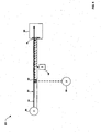
- FIG. 1 is a schematic diagram of an endoscopic system according to the present invention.
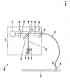
- FIG. 2 is a schematic diagram of another endoscopic system according to the present invention.
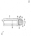
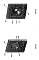
- FIG. 3 is a cross sectional view of a waveguide fitting portion of the endoscopic system shown in FIG. 2 .
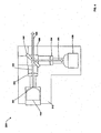
- FIG 4 is a schematic diagram of an optical sensor portion of the endoscopic system shown in FIG. 2 .
- FIG. 5 is a method for controlling an endoscope light source employable by the systems shown in FIG. 1 and FIG. 2 .
- FIG. 1 shows a schematic of an endoscopic system 50 according to the present invention.
- the system 50 includes visible light 52 being transmitted along an illumination path 54.
- the visible light 52 may originate from an illuminator 56.
- the system 50 also includes a source 58 for providing radiation along at least a portion of the illumination path 54. The radiation may be combined into the illumination path 54 via a combiner 60.
- the illumination attenuator 62 may be any device for receiving visible light.
- the illumination attenuator 62 is a device being capable of also transmitting or projecting a portion of the visible light.
- the illumination attenuator 62 may be an endoscope or a similar surgical instrument.
- the system 50 includes a reflector (e.g., first reflector 64) connected to the illumination attenuator 62 for reflecting at least a portion of the radiation received by the illumination attenuator 62.
- the first reflector 64 may be mounted within the illumination attenuator 62 or external to the illumination attenuator 62. In some embodiments, the first reflector 64 is in the illumination path 54 and transmits at least a portion of visible light received by the illumination attenuator 62.
- a detector 66 is included in the system 50.
- the detector 66 may receive a portion of radiation reflected from the first reflector 64.
- the detector 66 may further generate a signal (not shown) indicative of the receipt of visible light 52 by the illumination attenuator 62.
- the signal is provided to control the amount of visible light provided by an illuminator (e.g., illuminator 56).
- FIG. 2 shows a schematic of an exemplary embodiment of an endoscopic system 100 according to the present invention.
- the system 100 includes an illumination supply device 110.
- the illumination supply device 110 includes an illuminator 112 for providing visible light (e.g., visible light 52).
- the visible light may be provided at a first frequency or a first frequency range (e.g., within the visible range of the electromagnetic spectrum).
- the illuminator 112 may be any known illuminator, such as a xenon lamp.
- the illumination supply device 110 further includes a source 114 for providing radiation (e.g., detection radiation) at a second frequency or second frequency range.
- the second frequency range is less than the first frequency range (e.g., infrared radiation frequencies and visible light frequencies, respectively).
- the source 114 may be an IR light emitting diode ("LED") providing infrared ("IR") radiation.
- the second frequency range may be greater than the first frequency range (e.g., ultraviolet radiation frequencies and visible light frequencies, respectively).
- the source 114 may provide constant radiation or modulated radiation, i.e., at a particular pulse rate.
- the source 114 may provide radiation pulsed at 455 kHz with a 4.2 kHz envelope.
- the illumination supply device 110 of the endoscopic system 100 further includes a detector 116 (e.g., IR receiving module).
- the detector 116 may generate a signal upon the receipt or detection of particular radiation or light.
- the detector 116 may generate a signal upon the receipt of a specific frequencies or levels of radiation being reflected from a reflector and/or illuminator attenuator.
- the detector 116 may generate a signal when radiation pulsed at a particular pulse rate is received. For example, the detector 116 may only detect radiation being pulsed at a rate of 455 kHz within a 1-22.5 kHz envelope. Such limits on detection and signal generation are desirable to prevent interferants from being detected, such as fluorescent light, incandescent lights, sun light or the visible light (e.g., 52).
- the detector 116 may further include built-in electronics such as a demodulator and/or gain control (not shown).
- the endoscopic system 100 may include a waveguide 130 detachably connectable to the illumination supply device 110 (e.g., via a waveguide socket (not shown)).
- the waveguide 130 includes a proximal end 132 and a distal end 134.
- the waveguide 130 may be any waveguide or light cable for providing an illumination path, such as a fiber optic cable.
- the endoscopic system 100 further includes an illumination attenuator 140 (e.g., an endoscope) being connectable to the illumination supply device 110 via the waveguide 130.
- the illuminator attenuator 140 may include a waveguide fitting 150 (e.g., a light post connector) detachably connected to the distal end 134 of the waveguide 130.
- the waveguide fitting 150 includes a housing 210 having a first end 220 and a second end 230.
- the first end 220 includes a means to detachably connect the waveguide fitting 150 to the waveguide 130.
- the second end 230 includes a means to detachably connect to the illuminator attenuator 140.
- the second end 230 may be disconnected from the illuminator attenuator 140 only after the first end 220 is disconnected from the waveguide 130.
- Some embodiments of the waveguide fitting 150 may be adaptable to several known illumination attenuators (e.g., endoscopes) and waveguides. Therefore, the present invention may be readily implemented with (e.g., interchangeable between) existing endoscopic instruments, waveguides, and illumination supply devices.
- the waveguide fitting 150 includes a first reflector 250.
- the first reflector 250 may be, e.g., a "hot mirror" for transmitting the visible light and reflecting other light or radiation (e.g., radiation 260).
- the first reflector 250 may receive both visible light 260 and radiation 262 from the illumination supply device 110 via the waveguide 130.
- the first reflector 250 transmits a substantial portion of visible light 260 via the illuminator attenuator 140.
- the first reflector 250 reflects a substantial portion of radiation 262 to the detector 116 via the waveguide 130.
- the presence of the illumination attenuator 140 may therefore be determined by detecting (via detector 116) whether radiation is reflected (i.e., an illumination attenuator 140 is attached) or not reflected (i.e., the illumination attenuator 140 is detached).
- the first reflector 250 may include, e.g., a cold filter.
- a cold filter may be employed to reflect shorter wavelengths of light or radiation and transmit longer wavelengths.
- a cold filter may be used when the radiation has a higher frequency than the visible light.
- the first reflector 250 may include a notch filter to reflect one or more narrow bands of radiation or light and transmit wider regions of radiation around the rejected band(s).
- the first reflector 250 may further include a unique indicator (not shown).
- Such indicator may provide information (e.g., parameters) from the illuminator attenuator 140 to the illumination supply device 110 via the reflected radiation 264.
- the parameters may be stored in the indicator or provided to the indicator by a user via a remote control (not shown) on the illuminator attenuator 140.
- the parameters may include, for example, an illumination attenuator or endoscope type, serial number, maximum temperature, a maximum light level input, and/or the remote controls present.
- the indicator may include an integrated circuit providing parameters (e.g., instructions) to the illumination supply device 110, such as to adjust the intensity of the illuminator 112 in real time.
- the illumination supply device 110 may further include an optical element 118 (e.g., a "hot mirror” and/or a second reflector).
- the optical element 118 includes a first surface 120 and a second surface 122.
- the optical element 118 is positioned to receive visible light from the illuminator 112 via the first surface 120, and reflect radiation from (e.g., and to) the source 114 via the second surface 122.
- the optical element 118 may be positioned at approximately a forty-five degree angle relative to a first portion 124 (from the illuminator 112) and approximately a forty-five degree angle relative to a radiation path 128 (from the source 114).
- the first portion 124 is oriented ninety degrees relative to the radiation path 128.
- the optical element 118 may be implemented in conventional illumination supply devices, in part, by removing a current zero degree mirror and replacing it with the above described forty-five degree hot mirror.
- the orientation of the optical element 118 in the present invention allows for the rejection of radiation from the lamp (e.g., illuminator 112), but further creates a radiation path for the transmission of radiation to and from the detector 116.
- the optical element 118 may receive visible light from the illuminator 112 via a first portion 124 of an illumination path and transmit the visible light to the waveguide 130 (i.e., combined into the illumination path) via a second portion 126 (e.g., via a lens 136).
- the optical element 118 may further receive radiation (from the source 114) via a radiation path 128 and reflect the radiation to the waveguide 130 via the second portion 126. If the illuminator attenuator 140 is present (i.e., connected to the waveguide 130), the radiation, or a substantial portion thereof, will be reflected from the first reflector 250 and returned via the waveguide 130 and second portion 126.
- the optical element 118 may receive the reflected radiation via the second light 126 path and reflect the radiation to the detector 116 via the radiation path 128 (i.e., diverted from the illumination path).
- the illuminator 112 may be controlled (e.g., powered down or turned off) depending on the radiation received. For example, the illuminator 113 may provide visible light only while the detector 116 receives at least a predetermined amount or level of the radiation (e.g., radiation having the second frequency and/or radiation modulated at the particular pulse rate). The illuminator 112 may further not provide visible light when the detector 116 receives less than the predetermined amount of radiation.
- the illumination supply device 110 may include an iris 160 for controlling the illuminator 112.
- the iris 160 may block visible light, or any portion thereof, being provided by the illuminator 112.
- the iris 160 may be positioned along the first portion 124. As one of ordinary skill in the art will understand, such placement of the iris 160 will allow for the control of visible light without interrupting the transmission and/or reflection of the radiation.
- the iris 160 may (e.g., upon receiving information from the detector 116) block a substantial portion of the visible light when the detector 116 does not receive radiation within a specific frequency range (e.g., a detection frequency range) and/or particular pulse rate (e.g., repetition rate).
- a specific frequency range e.g., a detection frequency range
- particular pulse rate e.g., repetition rate
- the source 114 and the detector 116 may be integrated in an optical sensor 300.
- FIG. 4 shows a schematic diagram of the optical sensor 300 for detecting the presence of an endoscope according to the present invention.
- the optical sensor 300 includes a housing 310 and the source 114 (e.g., an infrared radiation source).
- the source 114 provides radiation along a source path 320.
- the source 114 may include a field stop 322 (e.g., 0.25mm pinhole). Further included may be a collimating lens 324 positioned along the source path 320.
- the optical sensor 300 further includes the detector 116 for receiving reflected radiation via a detection path 330.
- a focusing lens 334 may be included along the detection path 330.
- the optical sensor 300 includes a sensor reflector 340.
- the sensor reflector 340 may be any reflector and/or filter for allowing a portion of received radiation to pass through while reflecting another portion.
- the sensor reflector 340 may be a 50/50 infrared beam splitter.
- the sensor reflector 340 receives the radiation (e.g., provided at a specific detection frequency or range of detection frequencies) via the source path 320 and transmits the radiation to the illumination attenuator 140 via an output/return port 350 and the radiation path 328.
- the sensor reflector 340 may further receive reflected radiation, i.e., reflected from the first reflector 250 of the illumination attenuator 140, via the radiation path 328.
- the sensor reflector 340 then transmits a portion of reflected radiation to the detector 116 via the detection path 330.
- the optical sensor 300 may positively detect the presence of the endoscopic device 140 (i.e., attached to the waveguide 140) when the detector 116 receives reflected radiation within the detection frequency range (and/or a particular pulse rate). The detector 116 may then provide information to the system 100 to adjust or control the illuminator 112 as needed. The optic sensor 300 may detect the presence of the endoscopic device 140 at given time intervals, continuously, and/or upon command by the system 100.
- the optical sensor 300 is preferably small enough to fit in existing illumination supply devices. For example, one embodiment of the optical sensor 300 may include the following approximate dimensions: 26mm height, 24mm width, and 14mm thickness.
- FIG. 5 shows a method for controlling an endoscope light source according to the present invention.
- the method is described with respect to the system 100 shown in FIGS. 1-4 . However, one of ordinary skill in the art will understand that the method may be implemented in other systems and devices.
- the method includes a step 401 of transmitting radiation (e.g., a infrared radiation) along an illumination path.
- the radiation may, e.g., be transmitted at a detection frequency (and/or a pulse rate) to an endoscope via a waveguide.
- Step 403 includes detecting (e.g., via detector 116) the receipt of reflected radiation from the illumination path, e.g., being reflected from the first reflector 250 via the waveguide 130.
- a signal is generated that is indicative of an illumination attenuator being present and/or connected along the illumination path (step 405).
- the iris 160 may then be opened (or may remain open) allowing the illuminator 112 to transmit visible light (step 407). If the radiation is not received, a signal is generated that is indicative of an illumination attenuator not being present and/or being detached from the waveguide (step 409). The iris 160 may then be closed (or may remain closed) preventing the illuminator 112 from transmitting visible light (step 411).
- Advantages of the present invention include the provision of a system for accurately detecting the presence of an illuminator attenuator using radiation. Furthermore, the present invention provides a system to in which no electrical conductors need be connected to the endoscope to detect its presence.
- the electronics of the detection system may be contained within the illumination supply device and therefore no custom waveguide is required.
- a further advantage of the present invention is the provision of an optical detection system by which parameters of an endoscope or information may be provided to the illumination supply device via radiation.
- a further advantage of the present invention is the provision of the system being adaptable to existing endoscopic systems and components. It is contemplated that the present invention may be implemented in many existing illumination supply devices.
Description
- The invention relates to optical sensors, and more specifically to an endoscopic system having an optical detection means for determining the presence of an endoscope.
- Conventional endoscopes are often supplied with illumination from an external light source. Such light sources generally include high powered lamps, such as xenon lamps. The light sources are generally coupled to the endoscope by means of a detachable waveguide or fiber optic light cable.
- An endoscope may be disconnected from the waveguide while still energized by the light source. Light exiting from the waveguide may therefore cause damage if the waveguide is set down without the medical instrument attached. For example, the light may damage operating drapes, a patient's skin, or clothing. Therefore, it is desirable that the light exiting the waveguide be attenuated when the endoscope is determined to be disconnected from the waveguide.
- Some devices exist to determine the presence of a light cable on a light source. For example,
U.S. Patent 4,356,534 to Hattori discloses a light supply device having a means for detecting a connection between a connector of a cable and a light supply socket using a relay switch operated by a solenoid.U.S. Patent No. 4,433,675 to Konoshima discloses a light supply apparatus for an endoscope having a detecting section to detect the state of a coupling between a connector and a socket mounted on a housing of the light supply. However, Both Hattori and Konoshima disclose only means for detecting the presence of a connection between a connector and a socket of a light supply. Neither patent discloses a system for detecting the presence of an endoscope on a waveguide. -
U.S. Patent No. 6,110,107 to Bellahsene et al. discloses a fiber optic cable for supplying light to an endoscope and for detecting the presence of the endoscope. However, the specialized cable disclosed in Bellahsene requires electrical conductors running the length of the cable and a switch on the cable's end with a sensor configured to sense the proximity of the endoscope. Therefore, the teachings of Bellahsene may not be used to detect the presence of an endoscope in existing endoscopic systems without using the specialized cable. -
DE 199 47 812 A1 relates to an illumination system for endoscopes that have a light source with a controllable brightness. A hook-up cable containing a bundle of optic fibers is provided to transmit the light from the light source to a light guide situated in the endoscope and extending to a distal end of the endoscope. At least one fiber of the bundle of fibers is optically coupled to one end near the light source with a light sensor. The light sensor cooperates with the control unit to control the brightness of the light source. -
EP 1 772 096 A2 , which was only published after the priority date of this application, is directed at an endoscope light source safety system including visible light transmitted along an illumination path; a source for providing radiation along at least a portion of the illumination path; and illumination attenuator connectable to the illumination path for receiving the visible light and the radiation; a first reflector connected to the illumination attenuator. For reflecting at least a portion of the radiation received by the illumination attenuator; a combiner for combining the radiation from the source into the illumination path; and a detector for receiving at least a portion of the radiation reflected from the first reflector and for generating a signal indicative of the receipt of visible light by the illumination attenuator. - It is therefore desired to provide an improved system and method for detecting the presence of an illumination attenuator, such as an endoscope, along an illumination path. It is a further desired to provide such a system that is adaptable to existing illumination attenuator systems without the necessity for a specialized cable or waveguide.
- According, it is an object of the present invention to provide an endoscopic system having an optical detection means for determining the presence of an endoscope or any other illumination attenuator. It is a further object to provide the endoscopic system in which the system controls a light source providing illumination to the illumination attenuator.
- It is a further object of the present invention to provide an optical sensor for detecting the presence of an endoscope in an endoscopic system. It is a further object to provide the optical sensor is adaptable to existing endoscopic systems.
- These and other objectives are achieved by providing an optical sensor and system according to the appended claims 1 and 9.
- Methods disclosed in this specification are not part of the claimed invention.
-
FIG. 1 is a schematic diagram of an endoscopic system according to the present invention. -
FIG. 2 is a schematic diagram of another endoscopic system according to the present invention. -
FIG. 3 is a cross sectional view of a waveguide fitting portion of the endoscopic system shown inFIG. 2 . -
FIG 4 is a schematic diagram of an optical sensor portion of the endoscopic system shown inFIG. 2 . -
FIG. 5 is a method for controlling an endoscope light source employable by the systems shown inFIG. 1 andFIG. 2 . -
FIG. 1 shows a schematic of anendoscopic system 50 according to the present invention. Thesystem 50 includesvisible light 52 being transmitted along an illumination path 54. In some embodiments, thevisible light 52 may originate from anilluminator 56. Thesystem 50 also includes asource 58 for providing radiation along at least a portion of the illumination path 54. The radiation may be combined into the illumination path 54 via acombiner 60. - Further included in the
system 50 is anillumination attenuator 62. Theillumination attenuator 62 may be any device for receiving visible light. Preferably, theillumination attenuator 62 is a device being capable of also transmitting or projecting a portion of the visible light. For example, theillumination attenuator 62 may be an endoscope or a similar surgical instrument. - The
system 50 includes a reflector (e.g., first reflector 64) connected to theillumination attenuator 62 for reflecting at least a portion of the radiation received by theillumination attenuator 62. Thefirst reflector 64 may be mounted within theillumination attenuator 62 or external to theillumination attenuator 62. In some embodiments, thefirst reflector 64 is in the illumination path 54 and transmits at least a portion of visible light received by theillumination attenuator 62. - A
detector 66 is included in thesystem 50. Thedetector 66 may receive a portion of radiation reflected from thefirst reflector 64. Thedetector 66 may further generate a signal (not shown) indicative of the receipt ofvisible light 52 by theillumination attenuator 62. In some embodiments, the signal is provided to control the amount of visible light provided by an illuminator (e.g., illuminator 56). -
FIG. 2 shows a schematic of an exemplary embodiment of anendoscopic system 100 according to the present invention. Thesystem 100 includes anillumination supply device 110. Theillumination supply device 110 includes anilluminator 112 for providing visible light (e.g., visible light 52). The visible light may be provided at a first frequency or a first frequency range (e.g., within the visible range of the electromagnetic spectrum). Theilluminator 112 may be any known illuminator, such as a xenon lamp. - The
illumination supply device 110 further includes asource 114 for providing radiation (e.g., detection radiation) at a second frequency or second frequency range. In a preferred embodiment, the second frequency range is less than the first frequency range (e.g., infrared radiation frequencies and visible light frequencies, respectively). For example, thesource 114 may be an IR light emitting diode ("LED") providing infrared ("IR") radiation. In other embodiments, the second frequency range may be greater than the first frequency range (e.g., ultraviolet radiation frequencies and visible light frequencies, respectively). Thesource 114 may provide constant radiation or modulated radiation, i.e., at a particular pulse rate. For example, thesource 114 may provide radiation pulsed at 455 kHz with a 4.2 kHz envelope. - The
illumination supply device 110 of theendoscopic system 100 further includes a detector 116 (e.g., IR receiving module). Thedetector 116 may generate a signal upon the receipt or detection of particular radiation or light. For example, thedetector 116 may generate a signal upon the receipt of a specific frequencies or levels of radiation being reflected from a reflector and/or illuminator attenuator. - In some embodiments, the
detector 116 may generate a signal when radiation pulsed at a particular pulse rate is received. For example, thedetector 116 may only detect radiation being pulsed at a rate of 455 kHz within a 1-22.5 kHz envelope. Such limits on detection and signal generation are desirable to prevent interferants from being detected, such as fluorescent light, incandescent lights, sun light or the visible light (e.g., 52). Thedetector 116 may further include built-in electronics such as a demodulator and/or gain control (not shown). - As shown in
FIG. 2 , theendoscopic system 100 may include awaveguide 130 detachably connectable to the illumination supply device 110 (e.g., via a waveguide socket (not shown)). Thewaveguide 130 includes aproximal end 132 and adistal end 134. Thewaveguide 130 may be any waveguide or light cable for providing an illumination path, such as a fiber optic cable. Theendoscopic system 100 further includes an illumination attenuator 140 (e.g., an endoscope) being connectable to theillumination supply device 110 via thewaveguide 130. For example, theilluminator attenuator 140 may include a waveguide fitting 150 (e.g., a light post connector) detachably connected to thedistal end 134 of thewaveguide 130. - A cross sectional view of the waveguide fitting 150 is shown in
FIG. 3 . Thewaveguide fitting 150 includes ahousing 210 having afirst end 220 and asecond end 230. Thefirst end 220 includes a means to detachably connect the waveguide fitting 150 to thewaveguide 130. Thesecond end 230 includes a means to detachably connect to theilluminator attenuator 140. In some embodiments, thesecond end 230 may be disconnected from theilluminator attenuator 140 only after thefirst end 220 is disconnected from thewaveguide 130. Some embodiments of the waveguide fitting 150 may be adaptable to several known illumination attenuators (e.g., endoscopes) and waveguides. Therefore, the present invention may be readily implemented with (e.g., interchangeable between) existing endoscopic instruments, waveguides, and illumination supply devices. - The
waveguide fitting 150 includes a first reflector 250. In one embodiment, the first reflector 250 may be, e.g., a "hot mirror" for transmitting the visible light and reflecting other light or radiation (e.g., radiation 260). The first reflector 250 may receive bothvisible light 260 andradiation 262 from theillumination supply device 110 via thewaveguide 130. The first reflector 250 transmits a substantial portion ofvisible light 260 via theilluminator attenuator 140. The first reflector 250 reflects a substantial portion ofradiation 262 to thedetector 116 via thewaveguide 130. As explained in more detail below, the presence of theillumination attenuator 140 may therefore be determined by detecting (via detector 116) whether radiation is reflected (i.e., anillumination attenuator 140 is attached) or not reflected (i.e., theillumination attenuator 140 is detached). - In other embodiments, the first reflector 250 may include, e.g., a cold filter. As one of ordinary skill in the art will understand, a cold filter may be employed to reflect shorter wavelengths of light or radiation and transmit longer wavelengths. For example, a cold filter may be used when the radiation has a higher frequency than the visible light. In some other embodiments, the first reflector 250 may include a notch filter to reflect one or more narrow bands of radiation or light and transmit wider regions of radiation around the rejected band(s).
- The first reflector 250 may further include a unique indicator (not shown). Such indicator may provide information (e.g., parameters) from the
illuminator attenuator 140 to theillumination supply device 110 via the reflected radiation 264. The parameters may be stored in the indicator or provided to the indicator by a user via a remote control (not shown) on theilluminator attenuator 140. The parameters may include, for example, an illumination attenuator or endoscope type, serial number, maximum temperature, a maximum light level input, and/or the remote controls present. For example, the indicator may include an integrated circuit providing parameters (e.g., instructions) to theillumination supply device 110, such as to adjust the intensity of theilluminator 112 in real time. - As shown in
FIG. 2 , theillumination supply device 110 may further include an optical element 118 (e.g., a "hot mirror" and/or a second reflector). Theoptical element 118 includes afirst surface 120 and asecond surface 122. Theoptical element 118 is positioned to receive visible light from theilluminator 112 via thefirst surface 120, and reflect radiation from (e.g., and to) thesource 114 via thesecond surface 122. For example, theoptical element 118 may be positioned at approximately a forty-five degree angle relative to a first portion 124 (from the illuminator 112) and approximately a forty-five degree angle relative to a radiation path 128 (from the source 114). In the exemplary embodiment, thefirst portion 124 is oriented ninety degrees relative to theradiation path 128. - As one of ordinary skill in the art will understand, the
optical element 118 may be implemented in conventional illumination supply devices, in part, by removing a current zero degree mirror and replacing it with the above described forty-five degree hot mirror. The orientation of theoptical element 118 in the present invention allows for the rejection of radiation from the lamp (e.g., illuminator 112), but further creates a radiation path for the transmission of radiation to and from thedetector 116. - As shown in
FIG. 2 , theoptical element 118 may receive visible light from theilluminator 112 via afirst portion 124 of an illumination path and transmit the visible light to the waveguide 130 (i.e., combined into the illumination path) via a second portion 126 (e.g., via a lens 136). Theoptical element 118 may further receive radiation (from the source 114) via aradiation path 128 and reflect the radiation to thewaveguide 130 via thesecond portion 126. If theilluminator attenuator 140 is present (i.e., connected to the waveguide 130), the radiation, or a substantial portion thereof, will be reflected from the first reflector 250 and returned via thewaveguide 130 andsecond portion 126. Theoptical element 118 may receive the reflected radiation via thesecond light 126 path and reflect the radiation to thedetector 116 via the radiation path 128 (i.e., diverted from the illumination path). - If the
illuminator attenuator 140 is not present, little or no radiation will be returned via thewaveguide 130 or received by thedetector 116. Theilluminator 112 may be controlled (e.g., powered down or turned off) depending on the radiation received. For example, the illuminator 113 may provide visible light only while thedetector 116 receives at least a predetermined amount or level of the radiation (e.g., radiation having the second frequency and/or radiation modulated at the particular pulse rate). Theilluminator 112 may further not provide visible light when thedetector 116 receives less than the predetermined amount of radiation. - Shown in
FIG. 2 , theillumination supply device 110 may include aniris 160 for controlling theilluminator 112. For example, theiris 160 may block visible light, or any portion thereof, being provided by theilluminator 112. Theiris 160 may be positioned along thefirst portion 124. As one of ordinary skill in the art will understand, such placement of theiris 160 will allow for the control of visible light without interrupting the transmission and/or reflection of the radiation. Theiris 160 may (e.g., upon receiving information from the detector 116) block a substantial portion of the visible light when thedetector 116 does not receive radiation within a specific frequency range (e.g., a detection frequency range) and/or particular pulse rate (e.g., repetition rate). - In one embodiment of the present invention, the
source 114 and thedetector 116, described above, may be integrated in anoptical sensor 300.FIG. 4 shows a schematic diagram of theoptical sensor 300 for detecting the presence of an endoscope according to the present invention. - The
optical sensor 300 includes ahousing 310 and the source 114 (e.g., an infrared radiation source). Thesource 114 provides radiation along asource path 320. Thesource 114 may include a field stop 322 (e.g., 0.25mm pinhole). Further included may be acollimating lens 324 positioned along thesource path 320. Theoptical sensor 300 further includes thedetector 116 for receiving reflected radiation via adetection path 330. A focusinglens 334 may be included along thedetection path 330. - Shown in
FIG. 4 , theoptical sensor 300 includes a sensor reflector 340. The sensor reflector 340 may be any reflector and/or filter for allowing a portion of received radiation to pass through while reflecting another portion. For example, the sensor reflector 340 may be a 50/50 infrared beam splitter. The sensor reflector 340 receives the radiation (e.g., provided at a specific detection frequency or range of detection frequencies) via thesource path 320 and transmits the radiation to theillumination attenuator 140 via an output/return port 350 and theradiation path 328. The sensor reflector 340 may further receive reflected radiation, i.e., reflected from the first reflector 250 of theillumination attenuator 140, via theradiation path 328. The sensor reflector 340 then transmits a portion of reflected radiation to thedetector 116 via thedetection path 330. - The
optical sensor 300 may positively detect the presence of the endoscopic device 140 (i.e., attached to the waveguide 140) when thedetector 116 receives reflected radiation within the detection frequency range (and/or a particular pulse rate). Thedetector 116 may then provide information to thesystem 100 to adjust or control theilluminator 112 as needed. Theoptic sensor 300 may detect the presence of theendoscopic device 140 at given time intervals, continuously, and/or upon command by thesystem 100. Theoptical sensor 300 is preferably small enough to fit in existing illumination supply devices. For example, one embodiment of theoptical sensor 300 may include the following approximate dimensions: 26mm height, 24mm width, and 14mm thickness. -
FIG. 5 shows a method for controlling an endoscope light source according to the present invention. The method is described with respect to thesystem 100 shown inFIGS. 1-4 . However, one of ordinary skill in the art will understand that the method may be implemented in other systems and devices. The method includes a step 401 of transmitting radiation (e.g., a infrared radiation) along an illumination path. The radiation may, e.g., be transmitted at a detection frequency (and/or a pulse rate) to an endoscope via a waveguide. Step 403 includes detecting (e.g., via detector 116) the receipt of reflected radiation from the illumination path, e.g., being reflected from the first reflector 250 via thewaveguide 130. If reflected radiation is received (by detector 116), a signal is generated that is indicative of an illumination attenuator being present and/or connected along the illumination path (step 405). Theiris 160 may then be opened (or may remain open) allowing theilluminator 112 to transmit visible light (step 407). If the radiation is not received, a signal is generated that is indicative of an illumination attenuator not being present and/or being detached from the waveguide (step 409). Theiris 160 may then be closed (or may remain closed) preventing the illuminator 112 from transmitting visible light (step 411). - Advantages of the present invention include the provision of a system for accurately detecting the presence of an illuminator attenuator using radiation. Furthermore, the present invention provides a system to in which no electrical conductors need be connected to the endoscope to detect its presence. The electronics of the detection system may be contained within the illumination supply device and therefore no custom waveguide is required.
- A further advantage of the present invention is the provision of an optical detection system by which parameters of an endoscope or information may be provided to the illumination supply device via radiation.
- A further advantage of the present invention is the provision of the system being adaptable to existing endoscopic systems and components. It is contemplated that the present invention may be implemented in many existing illumination supply devices.
- Although the invention has been described with reference to a particular arrangement of parts, features and the like, these are not intended to exhaust all possible arrangements or features, and indeed many modifications and variations will be ascertainable to those of skill in the art within the scope of the appended claims.
Claims (14)
- Optical sensor for detecting the presence of an illumination attenuator comprising:an illumination attenuator (140);a housing (502) having a first aperture (510) for passing visible light (520) and a plurality of second apertures (514) circumscribing the first aperture (510);at least two sources (180), each for providing radiation (530) via at least one second aperture (514) to an illumination path;two or more detectors (182), each detector (182) for receiving reflected radiation (532) from the illumination path via at least one second aperture (514); andan optical element (118) for:transmitting the visible light (520) via the first aperture (510) to the illumination attenuator (140),receiving the radiation (530) from the at least one source (180) and transmitting at least a portion of the radiation (530) along the illumination path to the illumination attenuator (140),receiving returned radiation (532) from the illumination attenuator (140), andtransmitting at least a portion of the returned radiation (532) to at least one of the detectors (182),wherein a signal indicative of the presence of the illumination attenuator (140) is generated when at least one of the detectors (182) receives returned radiation (532), and wherein the illumination attenuator (140) is connectable to the illumination path for receiving said visible light (520) and returning at least a portion of the radiation (532) to said optical element (118).
- Optical sensor according to claim 1, the first aperture further for receiving a waveguide.
- Optical sensor according to claim 1, wherein at least one of the second apertures has an axis oriented about thirty degrees to an axis of the first aperture.
- Optical sensor according to claim 1, wherein said optical element (118) includes a first surface (120) and a second surface (122).
- Optical sensor according to claim 4, wherein said optical element (118) receives the visible light (520) incident on the first surface (120) and transmits the visible light via the second surface (122).
- Optical sensor according to claim 5, the visible light (520) being incident substantially normal to the first surface (120).
- Optical sensor according to claim 4, wherein said optical element (118) receives the radiation via the second surface (122) and reflects the radiation (530) via the second surface (122).
- Optical sensor according to claim 7, the radiation (530) being incident approximately 30 degrees from a normal to the second surface (122).
- Endoscope light source safety system, comprising:an optical sensor according to any preceding claim;visible light (520) transmitted along an illumination path;the sources (180) arranged in an array circumscribing the illumination path, each source (180) is angled toward the illumination path and is for providing radiation (530) along at least a portion of the illumination path; andthe detectors (182) arranged in an array circumscribing the illumination path, each detector (182) is angled toward the illumination path and at least one of the detectors (182) receiving via said optical element (118) a portion of the returned radiation (532) and generating a signal indicative of the receipt of visible light (520) by said illumination attenuator (140).
- System according to claim 9, wherein said optical element (118) further passes the visible light (520).
- System according to claim 9, wherein said housing (502) includes said array of sources (180) and said array of detectors (182).
- System according to claim 11, wherein said housing (502) further includes the optical element (118).
- System according to claim 9, wherein the illumination path includes a waveguide.
- System according to claim 9, wherein said illumination attenuator (140) is an endoscope.
Applications Claiming Priority (1)
| Application Number | Priority Date | Filing Date | Title |
|---|---|---|---|
| US11/370,717 US7556414B2 (en) | 2005-10-07 | 2006-03-08 | Endoscopic light source safety and control system with optical sensor |
Publications (3)
| Publication Number | Publication Date |
|---|---|
| EP1832225A2 EP1832225A2 (en) | 2007-09-12 |
| EP1832225A3 EP1832225A3 (en) | 2008-01-09 |
| EP1832225B1 true EP1832225B1 (en) | 2011-08-03 |
Family
ID=38162002
Family Applications (1)
| Application Number | Title | Priority Date | Filing Date |
|---|---|---|---|
| EP07001690A Active EP1832225B1 (en) | 2006-03-08 | 2007-01-26 | Optical sensor and endoscopic light source safety and control system with optical sensor |
Country Status (4)
| Country | Link |
|---|---|
| US (1) | US7556414B2 (en) |
| EP (1) | EP1832225B1 (en) |
| JP (1) | JP4597114B2 (en) |
| CA (1) | CA2564282C (en) |
Families Citing this family (9)
| Publication number | Priority date | Publication date | Assignee | Title |
|---|---|---|---|---|
| US7869016B2 (en) * | 2007-05-17 | 2011-01-11 | Ams Research Corporation | Fiber damage detection and protection device |
| JP5467756B2 (en) * | 2008-11-14 | 2014-04-09 | Hoya株式会社 | Endoscope device |
| JP5388732B2 (en) * | 2009-07-15 | 2014-01-15 | Hoya株式会社 | Medical observation system and processor |
| US8878920B2 (en) | 2011-07-12 | 2014-11-04 | Karl Storz Imaging, Inc. | Method and apparatus for protection from high intensity light |
| US10345571B2 (en) * | 2014-01-30 | 2019-07-09 | Karl Storz Endovision, Inc. | Intelligent light source |
| LT3558169T (en) | 2017-04-18 | 2022-02-10 | Edwards Lifesciences Corporation | Heart valve sealing devices and delivery devices therefor |
| US11040174B2 (en) | 2017-09-19 | 2021-06-22 | Edwards Lifesciences Corporation | Multi-direction steerable handles for steering catheters |
| US20200397302A1 (en) * | 2019-06-20 | 2020-12-24 | Ethicon Llc | Fluorescence imaging in a light deficient environment |
| US20220233062A1 (en) * | 2021-01-26 | 2022-07-28 | Arthrex, Inc. | Endoscope thermal reflector |
Family Cites Families (21)
| Publication number | Priority date | Publication date | Assignee | Title |
|---|---|---|---|---|
| JPS55130644A (en) | 1979-04-02 | 1980-10-09 | Olympus Optical Co | Camera device for endoscope |
| DE3169553D1 (en) | 1980-09-22 | 1985-05-02 | Olympus Optical Co | A laser device for an endoscope |
| JPS5757543A (en) * | 1980-09-22 | 1982-04-06 | Olympus Optical Co | Laser apparatus for endoscope |
| JPS6378912U (en) * | 1986-11-10 | 1988-05-25 | ||
| JPH08555A (en) * | 1994-06-16 | 1996-01-09 | Fuji Photo Optical Co Ltd | Illumination device of endoscope |
| US6293911B1 (en) * | 1996-11-20 | 2001-09-25 | Olympus Optical Co., Ltd. | Fluorescent endoscope system enabling simultaneous normal light observation and fluorescence observation in infrared spectrum |
| DE19947812C2 (en) * | 1999-10-05 | 2001-11-22 | Winter & Ibe Olympus | Illumination device for endoscopes with brightness control |
| JP2001321338A (en) * | 2000-05-16 | 2001-11-20 | Olympus Optical Co Ltd | Light source for endoscope |
| US6530882B1 (en) * | 2000-06-30 | 2003-03-11 | Inner Vision Imaging, L.L.C. | Endoscope having microscopic and macroscopic magnification |
| JP2002034913A (en) * | 2000-07-27 | 2002-02-05 | Asahi Optical Co Ltd | Optical system of light source device in electronic endoscope system |
| US6734411B1 (en) * | 2000-09-29 | 2004-05-11 | Lucent Technologies Inc. | Method and apparatus for controlling power levels of optical signals in optical fiber interconnects |
| US6986764B2 (en) * | 2000-12-15 | 2006-01-17 | Laserscope | Method and system for photoselective vaporization of the prostate, and other tissue |
| WO2003062799A2 (en) * | 2002-01-18 | 2003-07-31 | Newton Laboratories, Inc. | Spectroscopic diagnostic methods and system |
| US6511422B1 (en) * | 2002-04-30 | 2003-01-28 | Karl Storz Imaging, Inc. | Method and apparatus for protection from high intensity light |
| US6932809B2 (en) * | 2002-05-14 | 2005-08-23 | Cardiofocus, Inc. | Safety shut-off device for laser surgical instruments employing blackbody emitters |
| JP4390440B2 (en) * | 2002-10-31 | 2009-12-24 | Hoya株式会社 | Automatic dimming device for endoscope and electronic endoscope device |
| JP4394359B2 (en) * | 2003-02-17 | 2010-01-06 | Hoya株式会社 | Endoscope light source device |
| US7582057B2 (en) | 2004-02-24 | 2009-09-01 | Japan Atomic Energy Research Institute | Endoscopic system using an extremely fine composite optical fiber |
| JP4459662B2 (en) * | 2004-03-05 | 2010-04-28 | Hoya株式会社 | Adjustment mechanism |
| US7175353B2 (en) * | 2004-03-24 | 2007-02-13 | Chin Ju Liu | Duplex optical transceiver |
| US7563010B2 (en) | 2005-10-07 | 2009-07-21 | Karl Storz Endovision, Inc. | Endoscopic light source safety and control system with optical sensor |
-
2006
- 2006-03-08 US US11/370,717 patent/US7556414B2/en not_active Expired - Fee Related
- 2006-10-17 CA CA2564282A patent/CA2564282C/en not_active Expired - Fee Related
- 2006-11-29 JP JP2006322230A patent/JP4597114B2/en not_active Expired - Fee Related
-
2007
- 2007-01-26 EP EP07001690A patent/EP1832225B1/en active Active
Also Published As
| Publication number | Publication date |
|---|---|
| JP4597114B2 (en) | 2010-12-15 |
| US7556414B2 (en) | 2009-07-07 |
| EP1832225A3 (en) | 2008-01-09 |
| US20070093690A1 (en) | 2007-04-26 |
| EP1832225A2 (en) | 2007-09-12 |
| CA2564282C (en) | 2011-12-20 |
| CA2564282A1 (en) | 2007-09-08 |
| JP2007236921A (en) | 2007-09-20 |
Similar Documents
| Publication | Publication Date | Title |
|---|---|---|
| CA2562976C (en) | Endoscopic light source safety and control system with optical sensor | |
| EP1832225B1 (en) | Optical sensor and endoscopic light source safety and control system with optical sensor | |
| US7292323B2 (en) | Optical fiber detection method and system | |
| US10670817B2 (en) | Endoscopic LED light source | |
| US10537236B2 (en) | Anti-fogging device for endoscope | |
| US20070184402A1 (en) | Caries detection using real-time imaging and multiple excitation frequencies | |
| US7303397B2 (en) | Caries detection using timing differentials between excitation and return pulses | |
| EP0867151B1 (en) | Medical laser irradiation apparatus | |
| US6389205B1 (en) | Brightness-controlled endoscope illumination system | |
| JP2008080112A (en) | Endoscopic device with temperature based light source control | |
| JP2008284030A (en) | Illumination light detecting optical system, optical apparatus equipped with the same, and endoscopic apparatus | |
| CN110403560A (en) | Sterile endoscope sheath | |
| US20220354692A1 (en) | Surgical laser system with illumination | |
| JPH0157765B2 (en) | ||
| WO2023126344A1 (en) | Fiber-optic medical treatment apparatus for treatment of a urinary tract of a subject |
Legal Events
| Date | Code | Title | Description |
|---|---|---|---|
| PUAI | Public reference made under article 153(3) epc to a published international application that has entered the european phase |
Free format text: ORIGINAL CODE: 0009012 |
|
| AK | Designated contracting states |
Kind code of ref document: A2 Designated state(s): AT BE BG CH CY CZ DE DK EE ES FI FR GB GR HU IE IS IT LI LT LU LV MC NL PL PT RO SE SI SK TR |
|
| AX | Request for extension of the european patent |
Extension state: AL BA HR MK YU |
|
| RIN1 | Information on inventor provided before grant (corrected) |
Inventor name: BIRNKRANT, DASHIELL Inventor name: MORAHN, JOHN P. Inventor name: LANDRY, DANA J. Inventor name: PICARD, BRAD A. Inventor name: HOPKINS, VERNON |
|
| PUAL | Search report despatched |
Free format text: ORIGINAL CODE: 0009013 |
|
| AK | Designated contracting states |
Kind code of ref document: A3 Designated state(s): AT BE BG CH CY CZ DE DK EE ES FI FR GB GR HU IE IS IT LI LT LU LV MC NL PL PT RO SE SI SK TR |
|
| AX | Request for extension of the european patent |
Extension state: AL BA HR MK YU |
|
| 17P | Request for examination filed |
Effective date: 20080526 |
|
| 17Q | First examination report despatched |
Effective date: 20080624 |
|
| AKX | Designation fees paid |
Designated state(s): DE FR GB IT |
|
| GRAP | Despatch of communication of intention to grant a patent |
Free format text: ORIGINAL CODE: EPIDOSNIGR1 |
|
| RTI1 | Title (correction) |
Free format text: OPTICAL SENSOR AND ENDOSCOPIC LIGHT SOURCE SAFETY AND CONTROL SYSTEM WITH OPTICAL SENSOR |
|
| GRAS | Grant fee paid |
Free format text: ORIGINAL CODE: EPIDOSNIGR3 |
|
| GRAA | (expected) grant |
Free format text: ORIGINAL CODE: 0009210 |
|
| AK | Designated contracting states |
Kind code of ref document: B1 Designated state(s): DE FR GB IT |
|
| REG | Reference to a national code |
Ref country code: GB Ref legal event code: FG4D |
|
| REG | Reference to a national code |
Ref country code: DE Ref legal event code: R096 Ref document number: 602007016192 Country of ref document: DE Effective date: 20110929 |
|
| PLBE | No opposition filed within time limit |
Free format text: ORIGINAL CODE: 0009261 |
|
| STAA | Information on the status of an ep patent application or granted ep patent |
Free format text: STATUS: NO OPPOSITION FILED WITHIN TIME LIMIT |
|
| 26N | No opposition filed |
Effective date: 20120504 |
|
| REG | Reference to a national code |
Ref country code: DE Ref legal event code: R097 Ref document number: 602007016192 Country of ref document: DE Effective date: 20120504 |
|
| REG | Reference to a national code |
Ref country code: FR Ref legal event code: PLFP Year of fee payment: 10 |
|
| PGFP | Annual fee paid to national office [announced via postgrant information from national office to epo] |
Ref country code: IT Payment date: 20160128 Year of fee payment: 10 |
|
| PGFP | Annual fee paid to national office [announced via postgrant information from national office to epo] |
Ref country code: GB Payment date: 20160111 Year of fee payment: 10 Ref country code: FR Payment date: 20160126 Year of fee payment: 10 |
|
| GBPC | Gb: european patent ceased through non-payment of renewal fee |
Effective date: 20170126 |
|
| REG | Reference to a national code |
Ref country code: FR Ref legal event code: ST Effective date: 20170929 |
|
| PG25 | Lapsed in a contracting state [announced via postgrant information from national office to epo] |
Ref country code: FR Free format text: LAPSE BECAUSE OF NON-PAYMENT OF DUE FEES Effective date: 20170131 |
|
| PG25 | Lapsed in a contracting state [announced via postgrant information from national office to epo] |
Ref country code: GB Free format text: LAPSE BECAUSE OF NON-PAYMENT OF DUE FEES Effective date: 20170126 |
|
| PG25 | Lapsed in a contracting state [announced via postgrant information from national office to epo] |
Ref country code: IT Free format text: LAPSE BECAUSE OF NON-PAYMENT OF DUE FEES Effective date: 20170126 |
|
| P01 | Opt-out of the competence of the unified patent court (upc) registered |
Effective date: 20230527 |
|
| PGFP | Annual fee paid to national office [announced via postgrant information from national office to epo] |
Ref country code: DE Payment date: 20231219 Year of fee payment: 18 |