EP1826933A2 - Apparatus and method for performing initial cell search in a wireless communications system - Google Patents
Apparatus and method for performing initial cell search in a wireless communications system Download PDFInfo
- Publication number
- EP1826933A2 EP1826933A2 EP07102953A EP07102953A EP1826933A2 EP 1826933 A2 EP1826933 A2 EP 1826933A2 EP 07102953 A EP07102953 A EP 07102953A EP 07102953 A EP07102953 A EP 07102953A EP 1826933 A2 EP1826933 A2 EP 1826933A2
- Authority
- EP
- European Patent Office
- Prior art keywords
- psc
- processor
- input signal
- maximum
- code
- Prior art date
- Legal status (The legal status is an assumption and is not a legal conclusion. Google has not performed a legal analysis and makes no representation as to the accuracy of the status listed.)
- Withdrawn
Links
Images


Classifications
-
- H—ELECTRICITY
- H04—ELECTRIC COMMUNICATION TECHNIQUE
- H04B—TRANSMISSION
- H04B1/00—Details of transmission systems, not covered by a single one of groups H04B3/00 - H04B13/00; Details of transmission systems not characterised by the medium used for transmission
- H04B1/69—Spread spectrum techniques
- H04B1/707—Spread spectrum techniques using direct sequence modulation
- H04B1/7073—Synchronisation aspects
- H04B1/7083—Cell search, e.g. using a three-step approach
-
- H—ELECTRICITY
- H04—ELECTRIC COMMUNICATION TECHNIQUE
- H04B—TRANSMISSION
- H04B1/00—Details of transmission systems, not covered by a single one of groups H04B3/00 - H04B13/00; Details of transmission systems not characterised by the medium used for transmission
- H04B1/69—Spread spectrum techniques
- H04B1/707—Spread spectrum techniques using direct sequence modulation
- H04B1/7073—Synchronisation aspects
- H04B1/70735—Code identification
Definitions
- the present invention relates to user equipment (UE) synchronization to a base station. More specifically, the present invention relates to an improved initial cell search method and system.
- UE user equipment
- Figure 1 illustrates a wireless communication system.
- the communication system has a plurality of base stations 2 1 -2 n (2).
- Each base station 2 communicates with user equipments (UEs) 41-4n (4) within its operating area or cell 6 1 -6 n (6).
- UEs user equipments
- cell search When a UE 4 is first activated, it is unaware of its location and which base station 2 (or cell 6) to communicate. The process where the UE 4 determines the cell 4 to communicate with is referred to as "cell search.”
- each base station 2 transmits the same primary synchronization code (PSC) in a primary synchronization channel (PSCH).
- PSCH primary synchronization channel
- the PSCH is one timeslot out of fifteen for case 1 cell search (as shown in Figure 2a), such as slot 0 or in general K, or two timeslots for case 2 cell search (as shown in Figure 2b), such as slots 0 or in general K and K + 8 and 8.
- Each base station transmits the same PSC in the PSCH timeslot(s).
- SSCs secondary synchronization codes
- each PSC is transmitted at a different time offsets. The PSC offsets are at a set number of chips.
- the UE 14 determines the base station 12 to be synchronized to by searching the PSCH for received PSCs, such as using a matched filter.
- An example of the results of such a search are shown in Figure 4.
- peaks 26 1 -26 2 occur in the PSCH where there is a high correlation with the PSC code.
- the search results are accumulated over multiple frames to improve accuracy. Using the accumulated results, the PSC peak locations are determined in the PSCH.
- each base station 12 also simultaneously transmits secondary synchronization codes (SSCs), such as three, for both TDD case 1 and case 2.
- SSCs secondary synchronization codes
- the SSCs sent by each base station 14 are used to identify certain cell parameters, such as the code group and frame timing used by the cell.
- the UE 14 typically uses a correlator to detect the SSCs and the data modulated on them at each PSC peak identified in step I.
- the UE 14 to read the broadcast control channel.
- TDD step III typically, the UE 14 detects the midamble used in the broadcast channel and subsequently reads the broadcast channel.
- a drawback of the initial cell search system described above is that the performance of the second step (SSC detection) is governed by the quality of the received signal which could result in false detections if this signal is of poor quality. In past systems, the second step, receives no benefit from successful execution of step 1.
- the system and method of the present invention establishes a communication link between a user equipment (UE) and a base station in a communication system having a plurality of base stations which each transmit a common primary synchronization code (PSC) in a primary synchronization channel in conjunction with a base station specific secondary synchronization code (SSC) within a system frame, which receives with the UE an input signal including the PSC and SSC from at least one of the base stations.
- the UE analyzes the input signal to detect any received PSCs within a selected time period which has duration corresponding to the length of a system frame and determining a relative location of a strongest PSC within the selected time period.
- the input signal is then processed to remove the PSC from at least the determined PSC location.
- a secondary synchronization code (SSC) is then detected for the determined location from the processed signal.
- the communication link is then established using the detected SSCs.
- Figure 1 is an illustration of a wireless communication system.
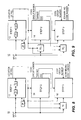
- FIGS 2a and 2b are illustrations of the physical synchronization channel (PSCH) for case 1 and case 2, respectively.
- Figure 3 is an illustration of peaks in a PSCH.
- Figure 4 is a block diagram of the initial cell search system of the present invention.
- Figure 5 is an exemplary block diagram of a step 2 processor.
- Figure 6 is an exemplary block diagram of a step 3 processor.
- Figure 7 is a flow diagram of the initial cell search system of the present invention.
- Figure 8 is a block diagram of a second embodiment of the initial cell search system.
- Figure 9 is a block diagram of a third embodiment of the initial cell search system.
- the initial cell search system 10 in accordance with the preferred embodiment of the present invention is illustrated in Figure 4.
- the system 10 comprises a step 1 processor 12, a cancellation device 18, a step 2 processor 14, and a step 3 processor 16, to accomplish initial synchronization between a user equipment (UE) and a base station.
- UE user equipment
- Step 1 of the initial cell search algorithm is accomplished using the step 1 processor 12.
- Figure 4 shows one implementation of a step 1 processor, although others may be used.
- the step 1 processor 12 comprises a Hierarchical Golay Correlator (HGC) 21 and a PSC decision device 22.
- the purpose of the step 1 processor 12 is to find the strongest base station's PSC over a frame or multiple frames worth of samples.
- a chip sampled input signal I is received by the UE and processed by the HGC 21.
- the HGC 21 is a reduced complexity implementation of the correlation process between PSC and the input signal I at consecutive chip locations.
- the output of the HGC 21 represents the magnitudes of the detected PSC power levels for those base stations detected by the HGC 21.
- the base stations' PSCs with a high received power level appear as peaks in the frame.
- the outputs from the HGC 21 are output to the PSC decision device 22.
- the PSC decision device 22 coupled to the HGC 21, receives the correlation values output by the HGC 21 for each chip in a frame worth of chips.
- a frame's worth of chips is preferably equivalent to the system frame, which by way of example, is equivalent to 38,400 chips.
- the system frame can be more or less than that which is used in this disclosure.
- the decision device 22 stores each chip correlation value from the HGC 21 over a predetermined number of frames N and averages each chip's correlation values.
- the HGC 21 outputs the correlation values A 1 , B 1 , C 1 , and D 1 , respectively for each of the four chips.
- the decision device 22 stores these values and receives the output of the next frame's correlation values for each chip from the HGC 21, which are A 2 , B 2 , C 2 , D 2 .
- Each chip's correlation values are then averaged, (i.e., A 1 ,+A 2 /2; B 1 +B 2 /2; C 1 +C 2 /2; D 1 +D 2 /2).
- the position of the maximum average of the frames is determined and its value compared with a determined threshold.
- the threshold is based on the noise level (i.e., interference plus thermal noise) at the receiver.
- the noise estimator 24 has an auxiliary HGC (not shown) that is based on a code which has very low cross correlation with the PSC and the SSCs.
- the noise estimator HGC calculates a noise estimate for every chip in the system frame.
- the noise estimator iterates over the same number of frames as the HGC 21 and averages several of the noise estimates in a window around the estimated PSCH location.
- the window size is preferably about 128, i.e., 64 chips on both sides of the PSCH location. As those having skill in the art know, the window size may be larger or smaller than 128.
- the decision device 22 determines whether the transmission pattern of the base station associated with the maximum average location is case 1 or case 2. This determination is made by comparing the correlation value of the chip at the maximum location +(8*2560) or maximum location +(7*2560). If this value is greater than the threshold , then the transmission pattern is case 2. Otherwise, the transmission is case 1.
- the step 1 processor 12 continues processing the input signal I until a correlation value greater than the threshold is found or a failed condition met.
- the decision processor 22 may utilize any of a number of methods for determining the location of the strongest PSC code. Once the maximum location is found, the decision processor 22 forwards the location and the PSC to the cancellation device 18 and the step 2 processor 14.
- the cancellation device 18, coupled to the step 1 processor 12 and the step 2 processor 14, takes the maximum location, the PSC and the input signal I and subtracts the PSC from the input signal I. This subtraction eliminates the PSC from the chip at the maximum location in the input signal I.
- the subtraction of the PSC from the input signal I can be done by one of several cancellation methods, such as interference cancellation.
- interference cancellation the PSC is converted, using an interference construction device (not shown), into an estimate of its contribution to the input signal I.
- the received PSC's contribution is subtracted, such as by a subtractor.
- the resulting signal has the PSC's contribution removed from the input signal I at the maximum location.
- code multiplexing systems one code appears as noise to other codes. Accordingly, the PSC is essentially noise to the SSC.
- the step 2 processor 14 is able to locate the SSC and slot offset with greater accuracy and speed.
- step 2 device comprises correlator 31, a fast Hadamard transform device (FHT) 33, phase estimator device 37, a derotate device 34, an accumulator 36, and a decision device 39. Since the location of the PSC has been determined by the step 1 processor 12, then the step 2 processor 14 need only search for the SSCs in the maximum location input from the step 1 processor 12. In this step, the UE identifies the code group and the t offset associated with the base station at the maximum location. The step 2 processor 14 also determines the frame index number within the interleaving period of two frames and it determines the slot index (K or K+8).
- FHT fast Hadamard transform device
- the modified input signal and the position of the PSC are input to the correlator 31.
- This code, C R is obtained from chip by chip multiplication of first SSC, C 1 , and a masking sequence, Z.
- R C (K) The 16 complex correlation values, R C (K) are obtained using the above code.
- t cp is the PSC position obtained from the step 1 processor 12 and N is the maximum number of PSCH time slots used for averaging.
- the correlation values obtained at the output of the correlator 31 are applied to the FHT 33.
- the FHT 33 is coupled to the correlator 31 and a derotate device 34, obtains 16 complex correlation values that correspond to the correlation of 16 SSCs and the received signal.
- FHT of R C (K)'s is equivalent to the correlation of unmasked SSCs with the received signal. This is possible due to the special structure of the 16 SSCs. Please note that a case 1 signal uses six (6) SSCs and a case 2 signal uses twelve (12) SSCs. Four (4) SSCs are unused.
- the phase estimator 37 receives the modified chip sampled received signal, as well as the PSC position from the step 1 processor 12.
- the output of the step 1 HGC 21 at the PSC position corresponds to the correlation of the PSC with the received signal at the PSC position.
- This complex correlation value is the input to the phase estimator 37.
- the complex correlation value is normalized and then conjugated. The phase estimation is necessary for the derotation of the SSCs.
- the derotate device 34 coupled to the phase estimator 37 and the FHT 33, receives the 16 SSCs from the FHT 33 and the phase estimation from the phase estimator 37.
- the derotate device 34 derotates the output of the FHT 33.
- the derotation phase is the phase of the PSC.
- the complex correlation values are complex multiplied with the phase.
- the derotated correlation values are then forwarded to the accumulator 36.
- the accumulator 36 is coupled to the derotate device 34 and the step 2 decision device 39.
- N is the maximum number of iterations to obtain a reliable signal value
- the decision variables obtained in the accumulator 36 are forwarded to the decision device 39.
- the decision device 39 compares all the decision variables sequentially (one by one). This scheme is efficient since the number of decision variables is not large and the scheme can be implemented without much complexity.
- the transmission pattern that the maximum decision variable belongs to indicates the code group number of case 1 and case 2 and PSCH slot index for case 2.
- the t offset , scrambling code group number, SSCs, and the location of the PSC are then forwarded to the step 3 processor 16.
- the step 3 processor 16 coupled to the step 2 processor 14, retrieves the midambles and primary scrambling code that are used by the UE.
- the code group number retrieved by the step 2 processor 14 is associated with four cell parameters. Therefore, identification of the code group number identifies the midamble codes used by the cell.
- the four cell parameters associated with the code group are cycled through System Frame Numbers (SFNs) as depicted in Table 1.
- SFNs System Frame Numbers
- FIG. 6 illustrates an exemplary step 3 processor 16. Although a step 3 processor is illustrated, any step 3 processor may be utilized.
- the step 3 processor 16 comprises a correlation device 41, an accumulation device 42, and a decision device 43.
- the correlation device 41 is forwarded to the code group and frame index from the step 2 processor 14, and the PSC position from the step 1 processor 12.
- a periodic window size pWS and multipath window size mpWS are also input to the correlation device 41.
- the input signal I is correlated with the four (4) midambles that are associated with the code group by the correlation device 41.
- the basic midamble code toggles with the SFN (odd/even). If the SFN is even, the correlation device 41 correlates against the basic midamble code. If the SFN is odd, the correlation device 41 correlates against the cycled midamble code. For example, in the case of code group 0, the correlation device 41 correlates against midamble codes 0,1,2 and 3 on even SFN, and the correlation device 41 correlates against midamble codes 1,0,3 and 2 on odd SFN. It should be noted that cell search does not know the SFN , but it does know whether the SFN is even or odd based on the frame index (1 or 2) found by the step 2 processor 14.
- the correlation device 41 calculates 4xWS3 correlations.
- the periodic window allows the correlation device 41 to find the maximum correlation.
- the purpose of the multipath window is to adjust the PSCH position to include the maximum amount of multipath. This may be necessary if the strongest multipath component is not the first significant multipath component.
- the correlation values output from the correlation device 41 are forwarded to the accumulation device 42 which is coupled to the correlation device 41 and the decision device 43.
- the accumulation device 42 accumulates the correlation values over a predetermined number of frames N3. It should be noted that initial cell search does not know frame boundaries so the initial cell search system typically uses blocks of 38400 chips (2560 chips x 15 slots) in lieu of frames.
- the accumulation device 42 forms the decision variables by adding the absolute value of the real and imaginary parts of the complex number that represents the correlation value.
- a decision variable is the magnitude measure of the corresponding correlation value. In order to have a more reliable decision, these decision variables can be accumulated for N3 iterations, where N3 is the maximum number of iterations for a reliable signal to noise ratio level.
- the decision variables generated by the accumulation device 42 are forwarded to the decision device 43.
- the decision device 43 coupled to the accumulation device 42, determines the maximum decision variable by simple sequential comparison.
- the maximum decision variable corresponds to the basic midamble used for the cell.
- the scrambling code number associated with the identified midamble is the scrambling code of the cell.
- the scrambling code is then utilized by the UE for broadcast channel processing.
- the flow diagram for the initial cell search system is illustrated in Figure 7.
- the UE receives the input signal over the common downlink channel (step 601).
- the step 1 processor 12 detects the location of the PSC associated with the strongest base station (step 602).
- the step 1 processor 12 forwards the PSC to the cancellation device 18 (step 603).
- the cancellation device 18 then subtracts the PSC detected from the step 1 processor 12 from the input signal I (step 604) and forwards this modified signal to the step 2 processor 14 (step 605).
- the step 2 processor 14 retrieves the SSCs and determines t offset and the code group number associated with the strongest base station (step 607).
- the code group number is then forwarded to the step 3 processor 16 (step 608) which retrieves the midambles and primary scrambling codes therefrom (step 609). These codes are then used by the UE to synchronize to the base station (step 610).
- the cancellation of the PSC from the signal input to the step 2 processor 14 provides a cleaner signal and results in a better estimation of the SSCs time. This results in a more accurate slot offset and code group number determination. Ultimately, this procedure reduces the number of false detections by the UE.
- a second embodiment is illustrated in Figure 8. Similar to the system of Figure 1, the system of this second embodiment utilizes a cancellation device 18 2 to subtract the PSC and SSCs from the input signal I before processing by the step 3 processor 16. Step 2 does not receive a PSC removed input signal, instead the modified input signal to the step 3 processor 16 is able to more accurately detect the midamble and code group of the detected base station.
- a third embodiment is illustrated in Figure 9.
- This third embodiment utilizes the cancellation devices 18 1 and 18 2 to improve the accuracy of the initial cell search system 10.
- the cancellation device 18 1 removes the PSC from the detected location in the input signal prior to the step 2 processor 14.
- the cancellation device 18 2 removes the SSCs prior to the step 3 processor 16.
Landscapes
- Engineering & Computer Science (AREA)
- Computer Networks & Wireless Communication (AREA)
- Signal Processing (AREA)
- Mobile Radio Communication Systems (AREA)
Abstract
Description
- BACKGROUND
- The present invention relates to user equipment (UE) synchronization to a base station. More specifically, the present invention relates to an improved initial cell search method and system.
- Figure 1 illustrates a wireless communication system. The communication system has a plurality of base stations 21-2n (2). Each
base station 2 communicates with user equipments (UEs) 41-4n (4) within its operating area or cell 61-6n (6). - When a UE 4 is first activated, it is unaware of its location and which base station 2 (or cell 6) to communicate. The process where the UE 4 determines the cell 4 to communicate with is referred to as "cell search."
- In typical code division multiple access (CDMA) communication systems, a multi-step process is used for cell search. For step one, each
base station 2 transmits the same primary synchronization code (PSC) in a primary synchronization channel (PSCH). In a time division duplex (TDD) communication system using CDMA, the PSCH is one timeslot out of fifteen forcase 1 cell search (as shown in Figure 2a), such as slot 0 or in general K, or two timeslots forcase 2 cell search (as shown in Figure 2b), such as slots 0 or in general K and K + 8 and 8. Each base station transmits the same PSC in the PSCH timeslot(s). To reduce interference between secondary synchronization codes (SSCs) used in step two, each PSC is transmitted at a different time offsets. The PSC offsets are at a set number of chips. - The UE 14 determines the
base station 12 to be synchronized to by searching the PSCH for received PSCs, such as using a matched filter. An example of the results of such a search are shown in Figure 4. As shown in Figure 4, peaks 261-262 occur in the PSCH where there is a high correlation with the PSC code. Typically, the search results are accumulated over multiple frames to improve accuracy. Using the accumulated results, the PSC peak locations are determined in the PSCH. - Referring back to Figure 2a and 2b, along with each base station's transmitted PSC, each
base station 12 also simultaneously transmits secondary synchronization codes (SSCs), such as three, for bothTDD case 1 andcase 2. The SSCs sent by eachbase station 14 are used to identify certain cell parameters, such as the code group and frame timing used by the cell. The UE 14 typically uses a correlator to detect the SSCs and the data modulated on them at each PSC peak identified in step I. The UE 14 to read the broadcast control channel. In TDD step III for both types I and II, typically, the UE 14 detects the midamble used in the broadcast channel and subsequently reads the broadcast channel. - A drawback of the initial cell search system described above is that the performance of the second step (SSC detection) is governed by the quality of the received signal which could result in false detections if this signal is of poor quality. In past systems, the second step, receives no benefit from successful execution of
step 1. - Accordingly, there is a need for an initial cell search system wherein the second step's performance is not solely governed by the received input signal, providing more accurate SSC detection.
- SUMMARY
- The system and method of the present invention establishes a communication link between a user equipment (UE) and a base station in a communication system having a plurality of base stations which each transmit a common primary synchronization code (PSC) in a primary synchronization channel in conjunction with a base station specific secondary synchronization code (SSC) within a system frame, which receives with the UE an input signal including the PSC and SSC from at least one of the base stations. The UE analyzes the input signal to detect any received PSCs within a selected time period which has duration corresponding to the length of a system frame and determining a relative location of a strongest PSC within the selected time period. The input signal is then processed to remove the PSC from at least the determined PSC location. A secondary synchronization code (SSC) is then detected for the determined location from the processed signal. The communication link is then established using the detected SSCs.
- BRIEF DESCRIPTION OF THE DRAWINGS
- Figure 1 is an illustration of a wireless communication system.
- Figures 2a and 2b are illustrations of the physical synchronization channel (PSCH) for
case 1 andcase 2, respectively. - Figure 3 is an illustration of peaks in a PSCH.
- Figure 4 is a block diagram of the initial cell search system of the present invention.
- Figure 5 is an exemplary block diagram of a
step 2 processor. - Figure 6 is an exemplary block diagram of a
step 3 processor. - Figure 7 is a flow diagram of the initial cell search system of the present invention.
- Figure 8 is a block diagram of a second embodiment of the initial cell search system.
- Figure 9 is a block diagram of a third embodiment of the initial cell search system.
- DETAILED DESCRIPTION OF THE PREFERRED EMBODIMENTS
- The preferred embodiments will be described with reference to the drawing figures where like numerals represent like elements throughout.
- The initial
cell search system 10 in accordance with the preferred embodiment of the present invention is illustrated in Figure 4. Thesystem 10 comprises astep 1processor 12, acancellation device 18, astep 2processor 14, and astep 3processor 16, to accomplish initial synchronization between a user equipment (UE) and a base station. -
Step 1 of the initial cell search algorithm is accomplished using thestep 1processor 12. Figure 4 shows one implementation of astep 1 processor, although others may be used. Thestep 1processor 12 comprises a Hierarchical Golay Correlator (HGC) 21 and aPSC decision device 22. The purpose of thestep 1processor 12 is to find the strongest base station's PSC over a frame or multiple frames worth of samples. A chip sampled input signal I is received by the UE and processed by the HGC 21. The HGC 21 is a reduced complexity implementation of the correlation process between PSC and the input signal I at consecutive chip locations. The output of the HGC 21 represents the magnitudes of the detected PSC power levels for those base stations detected by the HGC 21. The base stations' PSCs with a high received power level appear as peaks in the frame. The outputs from the HGC 21 are output to thePSC decision device 22. - The
PSC decision device 22, coupled to theHGC 21, receives the correlation values output by the HGC 21 for each chip in a frame worth of chips. A frame's worth of chips is preferably equivalent to the system frame, which by way of example, is equivalent to 38,400 chips. As those having skill in the art know, the system frame can be more or less than that which is used in this disclosure. - The
decision device 22 stores each chip correlation value from the HGC 21 over a predetermined number of frames N and averages each chip's correlation values. As an example, a system frame is 4 chips long, and N=2. TheHGC 21 outputs the correlation values A1, B1, C1, and D1, respectively for each of the four chips. Thedecision device 22 stores these values and receives the output of the next frame's correlation values for each chip from theHGC 21, which are A2, B2, C2, D2. Each chip's correlation values are then averaged, (i.e., A1,+A2/2; B1+B2/2; C1+C2/2; D1+D2/2). - Once the
decision device 22 finds the average correlation value for each average correlation chip in a frame, the position of the maximum average of the frames is determined and its value compared with a determined threshold. The threshold is based on the noise level (i.e., interference plus thermal noise) at the receiver. Thenoise estimator 24 has an auxiliary HGC (not shown) that is based on a code which has very low cross correlation with the PSC and the SSCs. The noise estimator HGC calculates a noise estimate for every chip in the system frame. The noise estimator iterates over the same number of frames as theHGC 21 and averages several of the noise estimates in a window around the estimated PSCH location. The window size is preferably about 128, i.e., 64 chips on both sides of the PSCH location. As those having skill in the art know, the window size may be larger or smaller than 128. - If the maximum average is greater than the threshold, the
decision device 22 determines whether the transmission pattern of the base station associated with the maximum average location iscase 1 orcase 2. This determination is made by comparing the correlation value of the chip at the maximum location +(8*2560) or maximum location +(7*2560). If this value is greater than the threshold , then the transmission pattern iscase 2. Otherwise, the transmission iscase 1. - If the maximum location value is less than the threshold, the
step 1processor 12 continues processing the input signal I until a correlation value greater than the threshold is found or a failed condition met. As those skilled in the art know, thedecision processor 22 may utilize any of a number of methods for determining the location of the strongest PSC code. Once the maximum location is found, thedecision processor 22 forwards the location and the PSC to thecancellation device 18 and thestep 2processor 14. - The
cancellation device 18, coupled to thestep 1processor 12 and thestep 2processor 14, takes the maximum location, the PSC and the input signal I and subtracts the PSC from the input signal I. This subtraction eliminates the PSC from the chip at the maximum location in the input signal I. The subtraction of the PSC from the input signal I can be done by one of several cancellation methods, such as interference cancellation. Using interference cancellation, the PSC is converted, using an interference construction device (not shown), into an estimate of its contribution to the input signal I. The received PSC's contribution is subtracted, such as by a subtractor. The resulting signal has the PSC's contribution removed from the input signal I at the maximum location. In code multiplexing systems, one code appears as noise to other codes. Accordingly, the PSC is essentially noise to the SSC. As a result, when the PSC is cancelled from the input signal I, thestep 2processor 14 is able to locate the SSC and slot offset with greater accuracy and speed. - The
step 2processor 14, coupled to thecancellation device 18, thestep 1processor 12 and thestep 3processor 16, receives the modified input signal from thecancellation device 18 and the location of the PSC from thestep 1processor 22. - One example of a
step 2 device is illustrated in Figure 5, although others may be used. Thisstep 2 device comprisescorrelator 31, a fast Hadamard transform device (FHT) 33,phase estimator device 37, aderotate device 34, anaccumulator 36, and adecision device 39. Since the location of the PSC has been determined by thestep 1processor 12, then thestep 2processor 14 need only search for the SSCs in the maximum location input from thestep 1processor 12. In this step, the UE identifies the code group and the toffset associated with the base station at the maximum location. Thestep 2processor 14 also determines the frame index number within the interleaving period of two frames and it determines the slot index (K or K+8). As those skilled in the art know, the toffset determined in this step allows the UE to synchronize to the slot bo cr (i) = c 1(i)*z(i), i=...,255 undary. The modified input signal and the position of the PSC are input to thecorrelator 31. Thecorrelator 31, coupled to theFHT 33 and thecancellation device 18, correlates the received input signal with the length 256 chip code at the PSC position to obtain 16 correlation values. This code, CR, is obtained from chip by chip multiplication of first SSC, C1, and a masking sequence, Z. This is shown below:

step 1processor 12 and N is the maximum number of PSCH time slots used for averaging. - The correlation values obtained at the output of the
correlator 31 are applied to theFHT 33. TheFHT 33 is coupled to thecorrelator 31 and aderotate device 34, obtains 16 complex correlation values that correspond to the correlation of 16 SSCs and the received signal. That is,
case 1 signal uses six (6) SSCs and acase 2 signal uses twelve (12) SSCs. Four (4) SSCs are unused. - The
phase estimator 37 receives the modified chip sampled received signal, as well as the PSC position from thestep 1processor 12. The output of thestep 1HGC 21 at the PSC position corresponds to the correlation of the PSC with the received signal at the PSC position. This complex correlation value is the input to thephase estimator 37. In thisphase estimator 37, the complex correlation value is normalized and then conjugated. The phase estimation is necessary for the derotation of the SSCs. - The
derotate device 34, coupled to thephase estimator 37 and theFHT 33, receives the 16 SSCs from theFHT 33 and the phase estimation from thephase estimator 37. Thederotate device 34 derotates the output of theFHT 33. The derotation phase is the phase of the PSC. The complex correlation values are complex multiplied with the phase. - The derotated correlation values are then forwarded to the
accumulator 36. Theaccumulator 36 is coupled to thederotate device 34 and thestep 2decision device 39. The derotated correlation values are added coherently with a period of two (for case 1) or four (for case 2), for N iterations in accordance with equation 4:
where N is the maximum number of iterations to obtain a reliable signal value, K is the number SSCs used (K=6 forcase 1 and K=12 for case 2) and L is periodicity of PSCH (L=2 forcase 1 and L=4 for case 2). These correlation values are initially set to zero. The decision variables are formed from the correlation values according to the SSC transmission patterns. - The decision variables obtained in the
accumulator 36 are forwarded to thedecision device 39. There are 64 decision variables forcase 1,32 code groups and 2 frames indices. Forcase 2, there are 128 decision variables, 32 code groups, 2 frame indices and 2 slots (K or K+8). Thedecision device 39 compares all the decision variables sequentially (one by one). This scheme is efficient since the number of decision variables is not large and the scheme can be implemented without much complexity. The transmission pattern that the maximum decision variable belongs to indicates the code group number ofcase 1 andcase 2 and PSCH slot index forcase 2. - The toffset, scrambling code group number, SSCs, and the location of the PSC are then forwarded to the
step 3processor 16. Thestep 3processor 16, coupled to thestep 2processor 14, retrieves the midambles and primary scrambling code that are used by the UE. The code group number retrieved by thestep 2processor 14 is associated with four cell parameters. Therefore, identification of the code group number identifies the midamble codes used by the cell. The four cell parameters associated with the code group are cycled through System Frame Numbers (SFNs) as depicted in Table 1.TABLE 1 Code Group Cell Parameter (initially assigned) Cell Parameter ( SFN mod 2 = 0)Cell Parameter ( SFN mod 2 = 1)i = 1,...,32 4(i-1) 4(i-1) 4(i-1)+1 4(i-1)+1 4(i-1)+1 4(i-1) 4(i-1)+2 4(i-1)+2 4(i-1)+3 4(i-1)+3 4(i-1)+3 4(i-1)+2 - Figure 6 illustrates an
exemplary step 3processor 16. Although astep 3 processor is illustrated, anystep 3 processor may be utilized. Thestep 3processor 16 comprises acorrelation device 41, anaccumulation device 42, and a decision device 43. Thecorrelation device 41 is forwarded to the code group and frame index from thestep 2processor 14, and the PSC position from thestep 1processor 12. A periodic window size pWS and multipath window size mpWS are also input to thecorrelation device 41. The input signal I is correlated with the four (4) midambles that are associated with the code group by thecorrelation device 41. The correlation is performed at WS3calculated candidate midamble locations on the P-CCPCH which are determined by the toffset of the code group, the periodic window size pWS and the multipath window size mpWS; where WS3 = pWS + 2mpWS. - The basic midamble code toggles with the SFN (odd/even). If the SFN is even, the
correlation device 41 correlates against the basic midamble code. If the SFN is odd, thecorrelation device 41 correlates against the cycled midamble code. For example, in the case of code group 0, thecorrelation device 41 correlates againstmidamble codes correlation device 41 correlates againstmidamble codes step 2processor 14. - The
correlation device 41 calculates 4xWS3 correlations. The periodic window allows thecorrelation device 41 to find the maximum correlation. The purpose of the multipath window is to adjust the PSCH position to include the maximum amount of multipath. This may be necessary if the strongest multipath component is not the first significant multipath component. - The correlation values output from the
correlation device 41, are forwarded to theaccumulation device 42 which is coupled to thecorrelation device 41 and the decision device 43. Theaccumulation device 42 accumulates the correlation values over a predetermined number of frames N3. It should be noted that initial cell search does not know frame boundaries so the initial cell search system typically uses blocks of 38400 chips (2560 chips x 15 slots) in lieu of frames. Theaccumulation device 42 forms the decision variables by adding the absolute value of the real and imaginary parts of the complex number that represents the correlation value. A decision variable is the magnitude measure of the corresponding correlation value. In order to have a more reliable decision, these decision variables can be accumulated for N3 iterations, where N3 is the maximum number of iterations for a reliable signal to noise ratio level. - The decision variables generated by the
accumulation device 42 are forwarded to the decision device 43. The decision device 43, coupled to theaccumulation device 42, determines the maximum decision variable by simple sequential comparison. The maximum decision variable corresponds to the basic midamble used for the cell. The scrambling code number associated with the identified midamble is the scrambling code of the cell. The scrambling code is then utilized by the UE for broadcast channel processing. - The flow diagram for the initial cell search system is illustrated in Figure 7. The UE receives the input signal over the common downlink channel (step 601). The
step 1processor 12 detects the location of the PSC associated with the strongest base station (step 602). Thestep 1processor 12 forwards the PSC to the cancellation device 18 (step 603). Thecancellation device 18 then subtracts the PSC detected from thestep 1processor 12 from the input signal I (step 604) and forwards this modified signal to thestep 2 processor 14 (step 605). Using the modified input signal from thecancellation device 18 and the location of the PSC from thestep 1processor 12, thestep 2processor 14 retrieves the SSCs and determines toffset and the code group number associated with the strongest base station (step 607). The code group number is then forwarded to thestep 3 processor 16 (step 608) which retrieves the midambles and primary scrambling codes therefrom (step 609). These codes are then used by the UE to synchronize to the base station (step 610). - Since the second step of the initial cell search is the weakest, the cancellation of the PSC from the signal input to the
step 2processor 14 provides a cleaner signal and results in a better estimation of the SSCs time. This results in a more accurate slot offset and code group number determination. Ultimately, this procedure reduces the number of false detections by the UE. - A second embodiment is illustrated in Figure 8. Similar to the system of Figure 1, the system of this second embodiment utilizes a
cancellation device 182 to subtract the PSC and SSCs from the input signal I before processing by thestep 3processor 16.Step 2 does not receive a PSC removed input signal, instead the modified input signal to thestep 3processor 16 is able to more accurately detect the midamble and code group of the detected base station. - A third embodiment is illustrated in Figure 9. This third embodiment utilizes the
cancellation devices cell search system 10. Thecancellation device 181 removes the PSC from the detected location in the input signal prior to thestep 2processor 14. Thecancellation device 182 removes the SSCs prior to thestep 3processor 16. -
-
Item 1. A method for establishing a communication link between a user equipment (UE) and a base station in a communication system having a plurality of base stations which each transmit a common primary synchronization code (PSC) in a primary synchronization channel in conjunction with a base station specific secondary synchronization code (SSC) within a system frame, the method comprising:- receiving with the UE an input signal including the PSC and SSC from at least one of the base stations;
- analyzing said input signal to detect received PSCs within a selected time period frame and determining a relative location of a strongest PSC within system frame; and
- processing said input signal to remove the PSC from at least the determined PSC location, and detecting a secondary synchronization code at the determined location from the processed signal.
-
Item 2. The method ofitem 1 further comprising the step of detecting a scrambling code number for determining cell parameters of a base station associated with said detected SSCs. -
Item 3. The method ofitem 2 wherein said removal of said detected PSC includes interference cancellation. - Item 4. The method of
item 1 further comprising the steps of:- processing said input signal to remove the PSC and SSC from at least the determined PSC location; and
- detecting a scrambling code number from the proces sed signal for determining cell parameters of a base station associated with said detected SSC.
- Item 5. The method of item 4 wherein said removal of said detected PSC and said SSC includes interference cancellation.
- Item 6. A communication system including a plurality of base stations which each transmit a common primary synchronization code (PSC) in a primary synchronization channel in conjunction with a base station specific secondary synchronization code (SSC) within a system frame, and a user equipment (UE) comprising a cell search system for establishing a communication link between a UE and a base station, the UE for receiving an input signal including the PSC and SSC from at least one of the base stations, said cell search system comprising:
- a first processor analyzing said input signal to detect received PSCs within a selected time period and determining a relative location of a strongest PSC within the system frame;
- a cancellation processor for processing said input signal to remove the PSC
- from at least the determined PSC location; and
- second processor for detecting said SSCs at the determined location from the processed signal.
- Item 7. The system of item 6 wherein said cell search system further comprises a third processor, responsive to said SSCs, for detecting a scrambling code number of the base station associated with said determined location.
-
Item 8. The system of item 7 wherein said cancellation processor uses interference cancellation to remove said PSC from said input signal. - Item 9. A user equipment (UE) comprising a cell search system for establishing a communication link between the UE and a base station in a communication system having a plurality of base stations which each transmit a common primary synchronization code (PSC) in a primary synchronization channel in conjunction with a base station specific secondary synchronization code (SSC) at a different time within a system frame,
- said UE receiving an input signal including the PSC and SSC from at least one of the base stations;
- said cell search system comprising:
- a first processor analyzing said input signal to detect received PSCs within a selected time period which has a duration corresponding to the length of a system frame and determining a relative location of a strongest PSC within the selected time period;
- a cancellation processor for processing said input signal to remove the PSC from at least the determined PSC location; and
- second processor for detecting said SSCs for the determined location from the processed signal;
- said system using the detected SSCs to establish the communication link.
-
Item 10. The UE of item 9 wherein said cell search system further comprises a third processor, responsive to said SSCs, for detecting a scrambling code number of the base station associated with said determined location. - Item 11. The UE of
item 10 wherein said cancellation processor uses interference cancellation to remove said PSC from said input signal. -
Item 12. A method for establishing a communication link between a user equipment (UE) and a base station in a communication system having a plurality of base stations which each transmit a common primary synchronization code (PSC) in a primary synchronization channel in conjunction with a base station specific secondary synchronization code (SSC) within a system frame, the method comprising:- receiving with the UE an input signal including the PSC and SSC from at least one of the base stations;
- analyzing said input signal to detect received PSCs within a selected time period frame and determining a relative location of a strongest PSC within system frame;
- detecting a secondary synchronization code at the determined location from said input signal; and
- processing said input signal to remove the PSC and SSC from at least the determined PSC location.
- Item 13. The method of
item 12 further comprising the step of detecting a scrambling code number from the processed signal for determining cell parameters of a base station associated with said detected SSC. -
Item 14. The method of item2 wherein said removal of said detected SSC includes interference cancellation.
Claims (8)
- A user equipment (UE) configured to perform initial cell search in a wireless communication system having a plurality of base stations, each base station transmitting a common primary synchronization code (PSC) in a primary synchronization channel in conjunction with a base station specific secondary synchronization code (SSC) at a different time within a system frame, said UE receiving an input signal including the PSC and SSC from at least one of the base stations;
said UE comprising:a step one processor for detecting PSCs within a selected time frame in said received input signal and determining a maximum PSC location, which corresponds to the maximum PSC value detected within the frame, and producing an output complex correlation value;a cancellation device for subtracting the PSC value at the maximum PSC location within the frame to enhance detection of the SSC;a step two processor, coupled to the step one processor and the cancellation device, configured to determine a scrambling code group number for the cell and a frame timing offset value for locating the frame boundary; anda step three processor, coupled to the step two processor, configured to determine the scrambling code of the cell. - The UE of claim 1 wherein said cancellation device uses interference cancellation to remove said PSC from said input signal.
- The UE of claim 1 wherein the step two processor comprises:a correlator configured to correlate the input signal with a code sequence corresponding to the maximum PSC location.
- The UE of claim 3 wherein the step two processor further comprises:a device configured to correlate the input signal with N SSCs outputting a set of N complex correlation values t, where N is an integer greater than one.
- The UE of claim 4 wherein the step two processor further comprises:a phase estimator device configured to determine a phase estimate of the complex correlation value from the step one processor; anda derotation device configured to derotate the set of N complex correlation values using the phase estimate.
- The UE of claim 5 wherein the step two processor further comprises:an accumulator configured to coherently add the derotated set of N correlation values at a predetermined period for a predetermined number of iterations, producing a set of decision variables; anda decision device configured to select a maximum decision variable, from which the scrambling code group number for the cell and the frame timing offset value are determined.
- The UE of claim 1 wherein the step three processor comprises:a step three correlation device configured to produce step three correlation values that are the maximum correlation of the input signal correlated with midambles associated with the code group;a step three accumulation device configured to accumulate the step three correlation values over a predetermined number of system frames producing step three decision variables; anda step three decision device configured to determine the maximum step three decision variable from which the basic midamble for the cell and the scrambling code of the cell is determined.
- The UE of claim 7 further comprising a second cancellation device coupled between the step two and step three processors configured to subtract the SSCs from the input signal to enhance detection of the code group number and midambles associated with the code group.
Applications Claiming Priority (3)
| Application Number | Priority Date | Filing Date | Title |
|---|---|---|---|
| US30041201P | 2001-06-22 | 2001-06-22 | |
| US09/998,885 US6894995B2 (en) | 2001-06-22 | 2001-10-31 | Apparatus and method for performing initial cell search in wireless communication systems |
| EP02746306A EP1407566B1 (en) | 2001-06-22 | 2002-04-15 | Apparatus and method for performing initial cell search in a wireless communications system |
Related Parent Applications (1)
| Application Number | Title | Priority Date | Filing Date |
|---|---|---|---|
| EP02746306A Division EP1407566B1 (en) | 2001-06-22 | 2002-04-15 | Apparatus and method for performing initial cell search in a wireless communications system |
Publications (2)
| Publication Number | Publication Date |
|---|---|
| EP1826933A2 true EP1826933A2 (en) | 2007-08-29 |
| EP1826933A3 EP1826933A3 (en) | 2007-09-05 |
Family
ID=38292940
Family Applications (1)
| Application Number | Title | Priority Date | Filing Date |
|---|---|---|---|
| EP07102953A Withdrawn EP1826933A3 (en) | 2001-06-22 | 2002-04-15 | Apparatus and method for performing initial cell search in a wireless communications system |
Country Status (1)
| Country | Link |
|---|---|
| EP (1) | EP1826933A3 (en) |
Citations (3)
| Publication number | Priority date | Publication date | Assignee | Title |
|---|---|---|---|---|
| WO2000055992A1 (en) * | 1999-03-17 | 2000-09-21 | Ericsson, Inc. | Synchronization and cell search method and apparatus for wireless communications |
| WO2000067399A1 (en) * | 1999-04-29 | 2000-11-09 | Samsung Electronics Co., Ltd. | Appararus and method for synchronizing channels in a w-cdma communication system |
| WO2001035564A2 (en) * | 1999-11-08 | 2001-05-17 | Ericsson Inc | Methods and apparatus for reducing synchronization code interference in cdma communications systems |
-
2002
- 2002-04-15 EP EP07102953A patent/EP1826933A3/en not_active Withdrawn
Patent Citations (3)
| Publication number | Priority date | Publication date | Assignee | Title |
|---|---|---|---|---|
| WO2000055992A1 (en) * | 1999-03-17 | 2000-09-21 | Ericsson, Inc. | Synchronization and cell search method and apparatus for wireless communications |
| WO2000067399A1 (en) * | 1999-04-29 | 2000-11-09 | Samsung Electronics Co., Ltd. | Appararus and method for synchronizing channels in a w-cdma communication system |
| WO2001035564A2 (en) * | 1999-11-08 | 2001-05-17 | Ericsson Inc | Methods and apparatus for reducing synchronization code interference in cdma communications systems |
Non-Patent Citations (1)
| Title |
|---|
| EUROPEAN TELECOMMUNICATIONS STANDARD INSTITUTE (ETSI): "Universal Mobile Telcommunications System (UMTS); UMTS Terrestrial Radio Access (UTRA); Concept evaluation (UMTS 30.06 version 3.0.0)" December 1997 (1997-12), , XP002131074 Chapter "2.6.4 Initial cell search" and Figure 23 * |
Also Published As
| Publication number | Publication date |
|---|---|
| EP1826933A3 (en) | 2007-09-05 |
Similar Documents
| Publication | Publication Date | Title |
|---|---|---|
| EP1407566B1 (en) | Apparatus and method for performing initial cell search in a wireless communications system | |
| US7158505B2 (en) | Periodic cell search | |
| EP1289163B1 (en) | Frequency offset correction circuit for WCDMA | |
| US6144691A (en) | Method and apparatus for synchronizing to a direct sequence spread spectrum signal | |
| US7072318B2 (en) | Cell search determination circuit | |
| US7023831B2 (en) | CDMA mobile communications apparatus and base station detecting method used therefor | |
| GB2367211A (en) | Slot timing acquisition and local oscillator frequency offset correction in a direct sequence spread spectrum receiver | |
| EP1215827B1 (en) | Cell search method to substract autocorrelation patterns from a correlation value profile | |
| US8761081B2 (en) | Method and apparatus for cell searching in asynchronous CDMA systems | |
| US7486656B2 (en) | Method and system for a mobile unit to synchronize with base station | |
| EP1826933A2 (en) | Apparatus and method for performing initial cell search in a wireless communications system | |
| US6539032B2 (en) | Methods for synchronizing between a base station and a mobile station in a cell-based mobile communications system | |
| KR100313928B1 (en) | Random Access Channel Synchronized Method in Communication System | |
| EP1599983A2 (en) | Method, system and apparatus for acquiring a received impulse radio signal | |
| KR101137344B1 (en) | Method and apparatus for estimating frame synchronization | |
| KR100828236B1 (en) | Initial cell search method | |
| KR100311528B1 (en) | Base-station searching method, and receiver for the method |
Legal Events
| Date | Code | Title | Description |
|---|---|---|---|
| PUAI | Public reference made under article 153(3) epc to a published international application that has entered the european phase |
Free format text: ORIGINAL CODE: 0009012 |
|
| PUAL | Search report despatched |
Free format text: ORIGINAL CODE: 0009013 |
|
| 17P | Request for examination filed |
Effective date: 20070223 |
|
| AC | Divisional application: reference to earlier application |
Ref document number: 1407566 Country of ref document: EP Kind code of ref document: P |
|
| AK | Designated contracting states |
Kind code of ref document: A2 Designated state(s): AT BE CH CY DE DK ES FI FR GB GR IE IT LI LU MC NL PT SE TR |
|
| AK | Designated contracting states |
Kind code of ref document: A3 Designated state(s): AT BE CH CY DE DK ES FI FR GB GR IE IT LI LU MC NL PT SE TR |
|
| 17Q | First examination report despatched |
Effective date: 20080328 |
|
| AKX | Designation fees paid |
Designated state(s): AT BE CH CY DE DK ES FI FR GB GR IE IT LI LU MC NL PT SE TR |
|
| STAA | Information on the status of an ep patent application or granted ep patent |
Free format text: STATUS: THE APPLICATION IS DEEMED TO BE WITHDRAWN |
|
| 18D | Application deemed to be withdrawn |
Effective date: 20081008 |