EP1826530B1 - Method and device for determining the circumference of a wheel - Google Patents
Method and device for determining the circumference of a wheel Download PDFInfo
- Publication number
- EP1826530B1 EP1826530B1 EP07001262A EP07001262A EP1826530B1 EP 1826530 B1 EP1826530 B1 EP 1826530B1 EP 07001262 A EP07001262 A EP 07001262A EP 07001262 A EP07001262 A EP 07001262A EP 1826530 B1 EP1826530 B1 EP 1826530B1
- Authority
- EP
- European Patent Office
- Prior art keywords
- wheel
- vehicle
- circumference
- rotational speed
- yaw rate
- Prior art date
- Legal status (The legal status is an assumption and is not a legal conclusion. Google has not performed a legal analysis and makes no representation as to the accuracy of the status listed.)
- Not-in-force
Links
Images
Classifications
-
- G—PHYSICS
- G01—MEASURING; TESTING
- G01B—MEASURING LENGTH, THICKNESS OR SIMILAR LINEAR DIMENSIONS; MEASURING ANGLES; MEASURING AREAS; MEASURING IRREGULARITIES OF SURFACES OR CONTOURS
- G01B21/00—Measuring arrangements or details thereof, where the measuring technique is not covered by the other groups of this subclass, unspecified or not relevant
- G01B21/10—Measuring arrangements or details thereof, where the measuring technique is not covered by the other groups of this subclass, unspecified or not relevant for measuring diameters
- G01B21/12—Measuring arrangements or details thereof, where the measuring technique is not covered by the other groups of this subclass, unspecified or not relevant for measuring diameters of objects while moving
-
- B—PERFORMING OPERATIONS; TRANSPORTING
- B60—VEHICLES IN GENERAL
- B60C—VEHICLE TYRES; TYRE INFLATION; TYRE CHANGING; CONNECTING VALVES TO INFLATABLE ELASTIC BODIES IN GENERAL; DEVICES OR ARRANGEMENTS RELATED TO TYRES
- B60C23/00—Devices for measuring, signalling, controlling, or distributing tyre pressure or temperature, specially adapted for mounting on vehicles; Arrangement of tyre inflating devices on vehicles, e.g. of pumps or of tanks; Tyre cooling arrangements
- B60C23/06—Signalling devices actuated by deformation of the tyre, e.g. tyre mounted deformation sensors or indirect determination of tyre deformation based on wheel speed, wheel-centre to ground distance or inclination of wheel axle
- B60C23/061—Signalling devices actuated by deformation of the tyre, e.g. tyre mounted deformation sensors or indirect determination of tyre deformation based on wheel speed, wheel-centre to ground distance or inclination of wheel axle by monitoring wheel speed
Definitions
- the invention relates to a method and a device for determining the circumference of vehicle wheels.
- the DE 103 06 498 describes a method for determining the wear on a tread of a vehicle wheel, wherein repeatedly a taking place while the vehicle vehicle revolution of the wheel and thereby actually occurring vehicle movement are evaluated and combined on a substrate.
- driver assistance systems can also provide more accurate results with accurate wheel circumferences, especially when accurate vehicle position determination is required.
- driver assistance systems include, for example, a parking aid which has to precisely measure a parking space or which enters a parking space along a desired path.
- the object of the present invention is to accurately determine the circumference of a wheel of a vehicle.
- this object is achieved by a method for determining the circumference of a wheel according to claim 1 and a device for determining the circumference of a wheel of a vehicle according to claim 10.
- the dependent claims define preferred and advantageous embodiments of the invention.
- the yaw rate is understood as meaning an angular velocity of a rotation of the vehicle about its vertical axis or yaw axis.
- the vertical axis or yaw axis is a vertical axis through the center of gravity of the vehicle, around which the vehicle turns during steering movements on a drive.
- the yaw rate and the first and second rotational speeds are measured values which change with time and can be determined, for example, via an ESP control device of the vehicle.
- the circumference of the wheel of the vehicle can also be determined relatively easily. It is particularly advantageous that the exact determination of the circumference of the wheel without external aids, such as satellite (GPS), is made possible, so that the determination is thus dynamic only with the vehicle usually already existing sensors. By accurately determining the scope then again a very accurate speed and position determination is possible.
- GPS satellite
- cornering is present when the yaw rate is significantly different from 0 ° / s and e.g. above 15 ° / s.
- the ratio X 1 between the circumference of the first wheel and the circumference of the second wheel can be determined in each case at a time at which the yaw rate integrated over a predetermined time interval has the value 0 °.
- each of the yaw rate, the first rotational speed, and the second rotational speed is started to be integrated. If, at a second time, which is later than the first time, the time integral of the yaw rate has the value 0 °, the ratio X 1 is determined from the equation (2). In this case, both the first and the second rotational speed have been integrated over a time interval which runs from the first to the second time point.
- the ratio X 1 between the circumference of the first wheel and the circumference of the second wheel can also be in a straight ahead of the vehicle from the first Determine the rotation speed DG 1 and the second rotation speed DG 2 by integrating the first rotation speed DG 1 and the second rotation speed DG 2 in time when traveling straight ahead, as indicated by the above formula (2).
- the circumference for each wheel of the vehicle may be determined depending on the yaw rate, the distance and a rotational speed for each wheel of the vehicle. This makes it possible, for example, to detect differences between the circumferences of different wheels of a vehicle and to detect, for example, wear of a wheel or air pressure fluctuations of a wheel.
- This is understood to mean a toe-in angle of a turned-in wheel of the vehicle under a steering angle.
- the steering angle is usually measured on the inside wheel and refers to the vehicle longitudinal center axis.
- the ratio X 1 may advantageously to new conditions, including a decline in tire pressure be adjusted.
- the ratio X1 can generally be determined more accurately, the longer the straight-ahead driving lasts or the more straight-ahead driving sections can be integrated continuously.
- the circumference U can, as a rule, be determined more precisely the more times N are included in the calculation.
- the calculation has to be rewritten from time to time to quickly notice changes caused, for example, by a decrease in tire pressure.
- This yaw rate correction size ⁇ kor to determine which one yaw rate measurand ⁇ Measurement, which is measured for example by the ESP control unit of the vehicle is corrected to that of yaw rate ⁇ determine with which finally the circumference of the first wheel and thus the peripheries of all the wheels of the vehicle can be accurately determined.
- This yaw rate correction quantity ⁇ kor is determined by the following formula at N times at which the vehicle is stationary, taking advantage of the fact that the yaw rate takes the value 0 when the vehicle is stationary.
- ⁇ kor ⁇ 1 N ⁇ measuring - 0 N ,
- the yaw rate correction variable can either be redetermined or determined at each new standstill of the vehicle by the averaging is continued continuously according to equation (4).
- the values given above for the boundary conditions may depend on the vehicle type. These values are usually determined for a particular vehicle type by vehicle tests. This applies both to the boundary conditions for determining the ratio X 1 between the circumference of the first and second wheels and to the boundary conditions for the precise determination of the circumference of the first wheel.
- the determination of the exact circumference of the other wheel may not necessarily be made in straight ahead travel, but may instead be performed at a time when a time integral of the yaw rate is 0 °.
- the wheel speed is calculated from a product of rotational speed and Normradun.
- a first wheel rotation speed is used instead of the second rotation speed at a second wheel rotation speed and a wheel rotation speed per wheel is used in the above equations (1) - (3) and (5).
- the use of the wheel rotational speed may have advantages when the wheel rotational speeds for the respective wheels, for which the exact circumference is to be determined, are already known, for example in an ESP control unit.
- the Normradun is a constant and corresponds in particular to a specification of the wheel manufacturer.
- the ESP control unit can be aware of the yaw rate ⁇ , the first V 1 and second V 2 wheel speed according to the invention determine the exact circumference U of the first wheel and based on the exact perimeters of the other wheels
- a device for accurately determining the circumference of a wheel of a vehicle having at least two wheels.
- the device determines the yaw rate of the vehicle and the first rotational speed of the first wheel and the second rotational speed of the second wheel of the vehicle and knows the track between the first and the second wheel.
- the device then the exact circumference of the first wheel according to the method described above.
- the present invention provides a vehicle comprising the above-described inventive device.
- the invention is preferably suitable for use in a motor vehicle. However, it is not limited to this preferred field of application, but may generally be applied to all devices having at least two wheels, such as e.g. Aircraft or trailers.
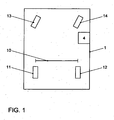
- Fig. 1 is a schematic representation of a vehicle according to the invention with a device according to the invention for determining the exact perimeters of the wheels of the vehicle.
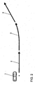
- Fig. 2 is a schematic representation showing a vehicle according to the invention and a track to be traveled by this vehicle.
- Fig. 1 schematically a vehicle 1 with four wheels 11-14 and a device 4 for determining the exact circumference of each wheel 11-14 is shown.
- the reference numeral 10 denotes the track width, ie the distance between the two rear wheels 11-12 of the vehicle 1.
- the device 4 eg an ESP control device, is able to determine the exact circumferences of the two rear wheels 11-12 on the basis of the measured variables of the first rotational speed of the first wheel 11 and the second rotational speed of the second wheel 12 and of the yaw rate of the vehicle. if the device 4, the track 10 is known.
- Fig. 2 With the help of Fig. 2 is described below how the device 4 on the in Fig. 2 illustrated track, which consists of two straight sections 2 and a curve section 3, the exact perimeters of the two rear wheels 11-12 and finally also determines the front wheels 13, 14 of the vehicle.
- a yaw rate correction quantity is calculated from the yaw rate measure, i. the yaw rate measured, since the yaw rate for a stationary vehicle by definition must be 0.
- the yaw rate measurand is corrected on the following driveway to determine the yaw rate with which, finally, the exact circumference of each wheel of the vehicle 1 is determined.
- the ratio X 1 between the circumference of the first wheel and the circumference of the second wheel is determined by integrating both the first rotational speed DG 1 of the first wheel and the second rotational speed DG 2 of the second wheel the vehicle 1 is traveling on the first straight section 2.
- the ratio X 1 between the circumference of the first wheel and the circumference of the second wheel is determined, as also described in advance with Equation (2).
- the exact circumference U of the first wheel 11 becomes dependent on the first rotation speed DG 1 of the first wheel 11, the second rotation speed DG 2 of the second wheel 12 and the yaw rate ⁇ with the aid of the track width 10 or 5 and the pre-calculated ratio X 1 between the circumference of the first wheel 11 and the circumference of the second wheel 12 at N different times determined and finally the exact circumference U of the first wheel 11 with reference to the above-described equation (1) or (3) determined.
- the peripheries of the remaining wheels 12-14 are determined from the now known exact circumference of the first wheel 11 and the rotational speeds of the four wheels 11-14 by the equation (5) described above.
- the rotational speeds of the four wheels 11-14 are determined and integrated via the ESP control unit.
- the integrated first rotational speeds are divided by the integrated rotational speeds of the particular wheel and the result multiplied by the predetermined exact circumference of the first wheel, resulting in the exact circumference of the particular wheel, as above in equation (5).
- the straight sections and the at least one curve section can, of course, also be taken from a normal route of a vehicle in which this determination is carried out.
- the rolling circumference of each wheel of a vehicle can be determined precisely.
- the distance covered by the vehicle can be determined very precisely, which is of great advantage, for example, for driver assistance systems (navigation system, parking aid).
- this can warn, for example, of a sinking air pressure or wear of a wheel, if the determined for this wheel circumference drops below a corresponding predetermined value.
Landscapes
- Physics & Mathematics (AREA)
- General Physics & Mathematics (AREA)
- Engineering & Computer Science (AREA)
- Mechanical Engineering (AREA)
- Control Of Driving Devices And Active Controlling Of Vehicle (AREA)
- Measuring Fluid Pressure (AREA)
- Steering Control In Accordance With Driving Conditions (AREA)
Abstract
Description
Die Erfindung betrifft eine Verfahren und eine Vorrichtung zur Umfangsermittlung von Fahrzeugrädern.The invention relates to a method and a device for determining the circumference of vehicle wheels.
Die
Über die genaue Kenntnis des Umfangs eines Fahrzeugrades kann der zurückgelegte Weg des Fahrzeugs genau ermittelt werden. Es gibt verschiedene Vorrichtungen im Fahrzeug, die von der Kenntnis des aktuellen Radumfangs profitieren. Zu diesen Vorrichtungen zählen beispielsweise eine Kilometer- und Geschwindigkeitsanzeige, eine Positionsbestimmung (Navigationssystem, insbesondere wenn kein hinreichend genaues Empfangssignal vorhanden ist) und eine Reifendruckkontrolle. Auch Fahrerassistenzsysteme können mit genauen Radumfängen genauere Ergebnisse liefern, insbesondere wenn eine genaue Fahrzeugpositionsbestimmung erforderlich ist. Zu diesen Fahrerassistenzsystemen gehört beispielsweise eine Einparkhilfe, welche eine Parklücke genau zu vermessen hat oder die entlang einer Sollbahn in eine Parklücke einfährt.On the exact knowledge of the scope of a vehicle wheel, the distance traveled by the vehicle can be accurately determined. There are various devices in the vehicle that benefit from the knowledge of the current wheel circumference. These devices include, for example, a mileage and speed display, a position determination (navigation system, in particular if no sufficiently accurate received signal is present) and a tire pressure control. Driver assistance systems can also provide more accurate results with accurate wheel circumferences, especially when accurate vehicle position determination is required. These driver assistance systems include, for example, a parking aid which has to precisely measure a parking space or which enters a parking space along a desired path.
In der vorliegenden Erfindung wird unter einem Umfang eines Rades der Abrollumfang dieses Rades verstanden, d.h. die Wegstrecke, welche je Umdrehung des Rades zurückgelegt wird. Die Radabrollumfänge der Räder eines Fahrzeugs sind nicht konstant. Sie können sich vielmehr beispielsweise aus folgenden Gründen verändern:
- Luftdruckschwankungen
- Fertigungstoleranzen der Räder
- Temperaturänderungen
- Verschleiß
- Radwechsel
- Air pressure fluctuations
- Manufacturing tolerances of the wheels
- temperature changes
- wear
- Changing a wheel
Daher ist die Aufgabe der vorliegenden Erfindung, den Umfang eines Rades eines Fahrzeugs genau zu ermitteln.Therefore, the object of the present invention is to accurately determine the circumference of a wheel of a vehicle.
Erfindungsgemäß wird diese Aufgabe durch ein Verfahren zur Umfangsermittlung eines Rades nach Anspruch 1 sowie eine Vorrichtung zur Umfangsermittlung eines Rades eines Fahrzeugs nach Anspruch 10 gelöst. Die abhängigen Ansprüche definieren bevorzugte und vorteilhafte Ausführungsformen der Erfindung.According to the invention, this object is achieved by a method for determining the circumference of a wheel according to
Im Rahmen der vorliegenden Erfindung wird der Umfang eines Rades eines Fahrzeugs mit mindestens zwei Rädern in Abhängigkeit von folgenden Messgrößen oder Parametern ermittelt:
- Gierrate
Ψ - erste Drehgeschwindigkeit DG1 eines ersten Rades, z.B. hinten links
- zweite Drehgeschwindigkeit DG2 eines zweiten Rades, z.B. hinten rechts
- Spurweite s zwischen dem ersten und dem zweiten Rad
- yaw rate
Ψ - first rotational speed DG 1 of a first wheel, eg rear left
- second rotational speed DG 2 of a second wheel, eg at the rear right
- Gauge s between the first and the second wheel
Dabei wird unter der Gierrate eine Winkelgeschwindigkeit einer Drehung des Fahrzeugs um seine Hochachse bzw. Gierachse verstanden. Die Hochachse bzw. Gierachse ist dabei eine vertikale Achse durch den Schwerpunkt des Fahrzeugs, um welche sich das Fahrzeug bei Lenkbewegungen auf einer Fahrt dreht.In this case, the yaw rate is understood as meaning an angular velocity of a rotation of the vehicle about its vertical axis or yaw axis. The vertical axis or yaw axis is a vertical axis through the center of gravity of the vehicle, around which the vehicle turns during steering movements on a drive.
Während die Spurweite zwischen dem ersten und dem zweiten Rad eine vorgegebene sich normalerweise nicht verändernde Größe des Fahrzeugs ist, sind die Gierrate und die erste und zweite Drehgeschwindigkeit Messgrößen, welche sich zeitlich ändern und beispielsweise über ein ESP-Steuergerät des Fahrzeugs ermittelt werden können.While the track between the first and second wheels is a predetermined normally non-changing size of the vehicle, the yaw rate and the first and second rotational speeds are measured values which change with time and can be determined, for example, via an ESP control device of the vehicle.
Da die Gierrate, die erste und zweite Drehgeschwindigkeit sowie der Abstand zwischen dem ersten und dem zweiten Rad relativ einfach ermittelt werden können, kann erfindungsgemäß auch der Umfang des Rades des Fahrzeugs relativ einfach bestimmt werden. Besonders vorteilhaft ist es dabei, dass die genaue Ermittlung des Umfangs des Rades ohne äußere Hilfsmittel, wie z.B. Satelliten (GPS), ermöglicht wird, so dass die Ermittlung also ausschließlich mit im Fahrzeug meist bereits vorhandener Sensorik dynamisch erfolgt. Durch die genaue Ermittlung des Umfangs ist dann wiederum eine sehr genaue Geschwindigkeits- und Positionsbestimmung möglich.Since the yaw rate, the first and second rotational speeds and the distance between the first and second wheels can be determined relatively easily, according to the invention the circumference of the wheel of the vehicle can also be determined relatively easily. It is particularly advantageous that the exact determination of the circumference of the wheel without external aids, such as satellite (GPS), is made possible, so that the determination is thus dynamic only with the vehicle usually already existing sensors. By accurately determining the scope then again a very accurate speed and position determination is possible.
Der Umfang U des ersten Rades wird abhängig von der Gierrate 
Dabei liegt eine Kurvenfahrt insbesondere vor, wenn die Gierrate deutlich von 0°/s verschieden ist und z.B. oberhalb von 15°/s liegt.In particular, cornering is present when the yaw rate is significantly different from 0 ° / s and e.g. above 15 ° / s.
Das Verhältnis X1 zwischen dem Umfang des ersten Rades und dem Umfang des zweiten Rades lässt sich dabei jeweils zu einem Zeitpunkt ermitteln, zu welchem die über ein vorbestimmtes Zeitintervall aufintegrierte Gierrate den Wert 0° aufweist. Zu diesem Zeitpunkt wird dann das Verhältnis X1 aus der ersten Drehgeschwindigkeit DG1 und der zweiten Drehgeschwindigkeit DG2 ermittelt, indem die erste Drehgeschwindigkeit DG1 und die zweite Drehgeschwindigkeit DG2 zeitlich über dieses Zeitintervall aufintegriert werden, wie es durch die folgende Formel angegeben ist: 
Anders ausgedrückt wird zu irgendeinem ersten Zeitpunkt begonnen, jeweils die Gierrate, die erste Drehgeschwindigkeit und die zweite Drehgeschwindigkeit aufzuintegrieren. Wenn zu einem zweiten Zeitpunkt, welcher zeitlich nach dem erstem Zeitpunkt liegt, das zeitliche Integral der Gierrate den Wert 0° aufweist, wird das Verhältnis X1 aus der Gleichung (2) ermittelt. Dabei ist dann sowohl die erste als auch die zweite Drehgeschwindigkeit über einem Zeitintervall, welches von dem ersten bis zu dem zweiten Zeitpunkt verläuft, aufintegriert worden.In other words, at any first time, each of the yaw rate, the first rotational speed, and the second rotational speed is started to be integrated. If, at a second time, which is later than the first time, the time integral of the yaw rate has the value 0 °, the ratio X 1 is determined from the equation (2). In this case, both the first and the second rotational speed have been integrated over a time interval which runs from the first to the second time point.
Das Verhältnis X1 zwischen dem Umfang des ersten Rades und dem Umfang des zweiten Rades lässt sich allerdings auch bei einer Geradeausfahrt des Fahrzeugs aus der ersten Drehgeschwindigkeit DG1 und der zweiten Drehgeschwindigkeit DG2 ermitteln, indem bei der Geradeausfahrt die erste Drehgeschwindigkeit DG1 und die zweite Drehgeschwindigkeit DG2 zeitlich aufintegriert werden, wie es durch die obige Formel (2) angegeben ist.However, the ratio X 1 between the circumference of the first wheel and the circumference of the second wheel can also be in a straight ahead of the vehicle from the first Determine the rotation speed DG 1 and the second rotation speed DG 2 by integrating the first rotation speed DG 1 and the second rotation speed DG 2 in time when traveling straight ahead, as indicated by the above formula (2).
Dabei liegt eine Geradeausfahrt des Fahrzeugs vor, wenn die Gierrate nahezu bei 0°/s liegt. Bei einer Geradeausfahrt wird erfindungsgemäß die Tatsache ausgenutzt, dass alle Räder des Fahrzeugs dieselbe Weglänge pro Zeiteinheit zurücklegen.This is a straight ahead of the vehicle, when the yaw rate is almost 0 ° / s. When driving straight ahead, the fact is exploited according to the invention that all the wheels of the vehicle cover the same path length per unit of time.
Vorteilhafter Weise kann abhängig von der Gierrate, dem Abstand und einer Drehgeschwindigkeit für jedes Rad des Fahrzeugs der Umfang für jedes Rad des Fahrzeugs bestimmt werden. Damit ist es beispielsweise möglich Unterschiede zwischen den Umfängen verschiedener Räder eines Fahrzeugs zu erfassen und daraus beispielsweise einen Verschleiß eines Rades oder Luftdruckschwankungen eines Rades zu erkennen.Advantageously, depending on the yaw rate, the distance and a rotational speed for each wheel of the vehicle, the circumference for each wheel of the vehicle may be determined. This makes it possible, for example, to detect differences between the circumferences of different wheels of a vehicle and to detect, for example, wear of a wheel or air pressure fluctuations of a wheel.
Um bei der Berechnung des Verhältnisses X1 störende Effekte, wie z.B. dynamische Veränderungen der Umfänge bei höheren Geschwindigkeiten und hohen Gierraten, zu vermeiden, kann es sinnvoll sein, die erste und die zweite Drehgeschwindigkeit nur dann zu erfassen und aufzuintegrieren, um durch die vorab angegebene Formel (2) das Verhältnis X1 zu berechnen, wenn folgende Randbedingungen gegeben sind:
- der Lenkwinkel des Fahrzeugs ist klein, z.B. betragsmäßig kleiner als 0,5°,
- die Geschwindigkeit des Fahrzeugs ist größer als 10km/h und kleiner als 50km/h,
- die Querbeschleunigung des Fahrzeugs ist klein, z.B. betragsmäßig kleiner als 1m/s/s,
- es liegt kein automatischer Eingriff, beispielsweise durch ESP, ABS, ASR, MSR usw. bei dem Fahrzeug vor, welcher die erste oder die zweite Drehgeschwindigkeit ungleichmäßig beeinflusst.
- the steering angle of the vehicle is small, eg less than 0.5 °,
- the speed of the vehicle is greater than 10km / h and less than 50km / h,
- the lateral acceleration of the vehicle is small, eg less than 1m / s / s,
- There is no automatic intervention, for example, by ESP, ABS, ASR, MSR, etc. in the vehicle, which affects the first or the second rotational speed unevenly.
Es sei darauf hingewiesen, dass die oben für die Randbedingungen genannten Werte an den jeweils entsprechenden Fahrzeugtyp angepasst werden können.It should be noted that the values mentioned above for the boundary conditions can be adapted to the respective vehicle type.
Dabei versteht man unter einem Lenkwinkel einen Vorspurwinkel eines eingeschlagenen Rades des Fahrzeugs. Der Lenkwinkel wird meist am kurveninneren Rad gemessen und bezieht sich auf die Fahrzeugslängsmittelachse.This is understood to mean a toe-in angle of a turned-in wheel of the vehicle under a steering angle. The steering angle is usually measured on the inside wheel and refers to the vehicle longitudinal center axis.
Indem das Verhältnis X1 andauernd neu berechnet wird, kann das Verhältnis X1 vorteilhafter Weise an neue Bedingungen, z.B. einen sinkenden Reifendruck, angepasst werden. Des Weiteren gilt, dass das Verhältnis X1 in der Regel umso genauer bestimmt werden kann, desto länger die Geradeausfahrt andauert oder je mehr Geradeausfahrtabschnitte kontinuierlich aufintegriert werden können.By the ratio X is recalculated continuously 1, the ratio X 1 may advantageously to new conditions, including a decline in tire pressure be adjusted. Of Furthermore, the ratio X1 can generally be determined more accurately, the longer the straight-ahead driving lasts or the more straight-ahead driving sections can be integrated continuously.
Um gegebenenfalls auftretende Messfehler auszumitteln, wird bei einer bevorzugten Ausführungsform der Erfindung der Umfang U des ersten Rades berechnet, indem dieser Umfang über N Zeitpunkte berechnet wird, und dann diese N berechneten Umfänge gemittelt werden, wie es in der folgenden Gleichung angegebenen ist: 
Ähnlich wie bei dem Verhältnis X1 kann der Umfang U in der Regel umso genauer bestimmt werden, je mehr Zeitpunkte N in die Berechnung einfließen. Auf der anderen Seite muss die Berechnung ab und an neu aufgesetzt werden, um Veränderungen, welche beispielsweise durch einen sinken Reifendruck verursacht werden, rasch zu bemerken.Similar to the ratio X 1 , the circumference U can, as a rule, be determined more precisely the more times N are included in the calculation. On the other hand, the calculation has to be rewritten from time to time to quickly notice changes caused, for example, by a decrease in tire pressure.
Da ein Unterschied zwischen der ersten Drehgeschwindigkeit und der zweiten Drehgeschwindigkeit bei einer geringen Gierrate relativ klein ist, ist es vorteilhaft, den Umfang nur zu ermitteln, wenn die Gierrate groß, z.B. größer als 15°/s ist.Since a difference between the first rotational speed and the second rotational speed is relatively small at a low yaw rate, it is advantageous to determine the circumference only when the yaw rate is large, e.g. greater than 15 ° / s.
Da die Gierrate eine zur Bestimmung des Umfangs des ersten Rades entscheidende Messgröße ist, ist es vorteilhaft, diese Gierrate möglichst korrekt zu ermitteln. Dazu kann eine Gierratenkorrekturgröße 
Die Gierratenkorrekturgröße kann dabei entweder bei jedem neuen Stillstand des Fahrzeugs neu bestimmt werden oder bestimmt werden, indem die Mittelwertbildung gemäß Gleichung (4) kontinuierlich fortgesetzt wird.The yaw rate correction variable can either be redetermined or determined at each new standstill of the vehicle by the averaging is continued continuously according to equation (4).
Ähnlich wie bei der Bestimmung des Verhältnisses X1 zwischen dem Umfang des ersten und des zweiten Rades kann es für die genaue Bestimmung des Umfanges des ersten Rades vorteilhaft sein, störende Effekte bei der Bestimmung des Umfanges zu vermeiden, indem der genaue Umfang nur bestimmt wird, wenn folgende Randbedingungen erfüllt sind:
- der Lenkwinkel des Fahrzeugs ist groß, z.B.
betragsmäßig größer als 3°, - die Geschwindigkeit des Fahrzeugs ist größer als 10km/h und kleiner als 50km/h,
- die Querbeschleunigung des Fahrzeugs ist klein, z.B. betragsmäßig kleiner als 1m/s/s,
- es liegt kein automatischer Eingriff, beispielsweise durch ESP, ABS, ASR, MSR usw. bei dem Fahrzeug vor, welcher die erste oder die zweite Drehgeschwindigkeit ungleichmäßig beeinflusst.
- The steering angle of the vehicle is large, eg, in terms of magnitude greater than 3 °,
- the speed of the vehicle is greater than 10km / h and less than 50km / h,
- the lateral acceleration of the vehicle is small, eg less than 1m / s / s,
- There is no automatic intervention, for example, by ESP, ABS, ASR, MSR, etc. in the vehicle, which affects the first or the second rotational speed unevenly.
Ähnlich wie bei den Randbedingungen zur Bestimmung des Verhältnisses X1 zwischen dem Umfang des ersten und des zweiten Rades können die oben für die Randbedingungen angegebenen Werte vom Fahrzeugtyp abhängen. Diese Werte werden in aller Regel für einen bestimmten Fahrzeugtyp durch Fahrzeugtests bestimmt. Dies gilt sowohl für die Werte für die Randbedingungen zur Bestimmung des Verhältnisses X1 zwischen dem Umfang des ersten und des zweiten Rades als auch für die Randbedingungen für die genaue Bestimmung des Umfanges des ersten Rades.Similar to the boundary conditions for determining the ratio X 1 between the circumference of the first and second wheels, the values given above for the boundary conditions may depend on the vehicle type. These values are usually determined for a particular vehicle type by vehicle tests. This applies both to the boundary conditions for determining the ratio X 1 between the circumference of the first and second wheels and to the boundary conditions for the precise determination of the circumference of the first wheel.
Wenn der Umfang U, des ersten Rades einmal genau bestimmt worden ist, kann durch diesen Umfang U, und die Drehgeschwindigkeit DG1 des ersten Rades der Umfang Ua eines anderen Rades des Fahrzeugs durch Ermittlung der Drehgeschwindigkeit DGa dieses anderen Rades durch folgende Formel bei einer Geradeausfahrt des Fahrzeugs ermittelt werden: 
In ähnlicher Weise wie bei der vorab beschriebenen Ermittlung des Verhältnisses X1 muss auch die Bestimmung des genauen Umfangs des anderen Rades nicht unbedingt bei einer Geradeausfahrt durchgeführt werden, sondern kann stattdessen zu einem Zeitpunkt durchgeführt werden, zu welchem ein zeitliches Integral der Gierrate den Wert 0° aufweist.Similarly as in the above-described determination of the ratio X 1 , the determination of the exact circumference of the other wheel may not necessarily be made in straight ahead travel, but may instead be performed at a time when a time integral of the yaw rate is 0 °.
Anstelle der Drehgeschwindigkeit kann auch mit einer Raddrehgeschwindigkeit gearbeitet werden. Dabei wird die Raddrehgeschwindigkeit aus einem Produkt aus Drehgeschwindigkeit und Normradumfang berechnet. Bei Verwendung der Raddrehgeschwindigkeit wird anstelle der ersten Drehgeschwindigkeit mit einer ersten Raddrehgeschwindigkeit, anstelle der zweiten Drehgeschwindigkeit mit einer zweiten Raddrehgeschwindigkeit und anstelle der Drehgeschwindigkeit pro Rad mit einer Raddrehgeschwindigkeit pro Rad in den oberen Gleichungen (1) - (3) und (5) gearbeitet.Instead of the rotational speed can also be used with a Raddrehgeschwindigkeit. The wheel speed is calculated from a product of rotational speed and Normradumfang. When using the wheel rotation speed, instead of the first rotation speed, a first wheel rotation speed is used instead of the second rotation speed at a second wheel rotation speed and a wheel rotation speed per wheel is used in the above equations (1) - (3) and (5).
Die Verwendung der Raddrehgeschwindigkeit kann Vorteile aufweisen, wenn die Raddrehgeschwindigkeiten für die entsprechenden Räder, für welche der genaue Umfang zu bestimmen ist, bereits beispielsweise in einem ESP-Steuergerät bekannt sind. Der Normradumfang ist dabei eine Konstante und entspricht insbesondere einer Vorgabe des Radherstellers.The use of the wheel rotational speed may have advantages when the wheel rotational speeds for the respective wheels, for which the exact circumference is to be determined, are already known, for example in an ESP control unit. The Normradumfang is a constant and corresponds in particular to a specification of the wheel manufacturer.
Während sich bei den obigen Gleichungen (2) und (4) der Normradumfang bei einer Verwendung der Raddrehgeschwindigkeiten anstelle der Drehgeschwindigkeiten herauskürzt, kürzt er sich in den Gleichungen (1) und (3) nicht heraus, so dass anstelle der Gleichung (1) dann die folgende Gleichung (6) und anstelle der Gleichung (3) dann die folgende Gleichung (7) gilt, wenn UN der Normradumfang und V1 bzw. V2 die Raddrehgeschwindigkeit des ersten bzw. zweiten Rades ist: 

Da der Normradumfang UN und die Spurweite s beispielsweise einem ESP-Steuergerät bekannt sind, kann das ESP-Steuergerät bei Kenntnis der Gierrate
Im Rahmen der vorliegenden Erfindung wird auch eine Vorrichtung bereitgestellt, um den Umfang eines Rades eines Fahrzeugs mit mindestens zwei Rädern genau zu bestimmen. Dabei ermittelt die Vorrichtung die Gierrate des Fahrzeugs sowie die erste Drehgeschwindigkeit des ersten Rades und die zweite Drehgeschwindigkeit des zweiten Rades des Fahrzeugs und kennt die Spurweite zwischen dem ersten und dem zweiten Rad. Abhängig von der Gierrate sowie der ersten und zweiten Drehgeschwindigkeit und der Spurweite bestimmt die Vorrichtung dann den genauen Umfang des ersten Rades gemäß dem vorab beschriebenen Verfahren.In the context of the present invention, a device is also provided for accurately determining the circumference of a wheel of a vehicle having at least two wheels. The device determines the yaw rate of the vehicle and the first rotational speed of the first wheel and the second rotational speed of the second wheel of the vehicle and knows the track between the first and the second wheel. Depending on the yaw rate and the first and second rotational speed and the track determined the device then the exact circumference of the first wheel according to the method described above.
Die Vorteile dieser erfindungsgemäßen Vorrichtung entsprechen den Vorteilen des erfindungsgemäßen Verfahrens, welche vorab detailliert ausgeführt worden sind, weshalb auf eine Wiederholung hier verzichtet wird.The advantages of this device according to the invention correspond to the advantages of the method according to the invention, which have been described in detail in advance, which is why a repetition is omitted here.
Schließlich stellt die vorliegende Erfindung ein Fahrzeug bereit, welches die vorab beschriebene erfindungsgemäße Vorrichtung umfasst.Finally, the present invention provides a vehicle comprising the above-described inventive device.
Die Erfindung eignet sich vorzugsweise zum Einsatz in einem Kraftfahrzeug. Sie ist aber nicht auf diesen bevorzugten Anwendungsbereich beschränkt, sondern kann generell bei allen Vorrichtungen mit mindestens zwei Rädern, wie z.B. Flugzeugen oder Anhängern, eingesetzt werden.The invention is preferably suitable for use in a motor vehicle. However, it is not limited to this preferred field of application, but may generally be applied to all devices having at least two wheels, such as e.g. Aircraft or trailers.
Die vorliegende Erfindung wird nachfolgend näher unter Bezugnahme auf die beigefügte Zeichnung anhand bevorzugter Ausführungsformen erläutert.The present invention will be explained in more detail below with reference to the accompanying drawings with reference to preferred embodiments.
In
Mit Hilfe der
Da sich das Fahrzeug 1 zu Beginn der Fahrt im Stillstand befindet, wird eine Gierratenkorrekturgröße aus der Gierratenmessgröße, d.h. der gemessenen Gierrate bestimmt, da die Gierrate bei einem stillstehenden Fahrzeug per Definition 0 betragen muss. Mit dieser Gierratenkorrekturgröße wird die Gierratenmessgröße auf dem folgenden Fahrweg korrigiert, um die Gierrate zu ermitteln, mit welcher schließlich der genaue Umfang jedes Rades des Fahrzeugs 1 bestimmt wird.Since the
Auf dem folgenden ersten geraden Teilstück 2 wird das Verhältnis X1 zwischen dem Umfang des ersten Rades und dem Umfang des zweiten Rades bestimmt, indem sowohl die erste Drehgeschwindigkeit DG1 des ersten Rades als auch die zweite Drehgeschwindigkeit DG2 des zweiten Rades aufintegriert werden, während das Fahrzeug 1 auf dem ersten geraden Teilstück 2 fährt. Indem die aufintegrierten ersten Drehgeschwindigkeiten durch die aufintegrierten zweiten Drehgeschwindigkeiten geteilt werden, wird das Verhältnis X1 zwischen dem Umfang des ersten Rades und dem Umfang des zweiten Rades bestimmt, wie es auch vorab mit der Gleichung (2) beschrieben ist.On the following first
Auf dem dem ersten geraden Teilstück 2 folgenden Kurventeilstück 3 wird der genaue Umfang U des ersten Rades 11 abhängig von der ersten Drehgeschwindigkeit DG1 des ersten Rades 11, der zweiten Drehgeschwindigkeit DG2 des zweiten Rades 12 und der Gierrate
Auf dem dem Kurventeilstück 3 folgenden geraden Teilstück 2 werden dann die Umfänge der restlichen Räder 12-14 ausgehend von dem nunmehr bekannten genauen Umfang des ersten Rades 11 und der Drehgeschwindigkeiten der vier Räder 11-14 durch die oben beschriebene Gleichung (5) ermittelt. Dabei werden, während das Fahrzeug 1 auf diesem geraden Teilstück 2 fährt, die Drehgeschwindigkeiten der vier Räder 11-14 über das ESP-Steuergerät ermittelt und aufintegriert. Um den genauen Umfang eines bestimmten Rades zu ermitteln, werden die aufintegrierten ersten Drehgeschwindigkeiten durch die aufintegrierten Drehgeschwindigkeiten des bestimmten Rades geteilt und das Ergebnis mit dem vorab ermittelten genauen Umfang des ersten Rades multipliziert, woraus sich der genaue Umfang des bestimmten Rades ergibt, wie dies oben in Gleichung (5) angegeben ist.On the
Die für die genaue Ermittlung der Umfänge aller Räder benötigten Fahrwegteilstücke, d.h. die geraden Teilstücke und das mindestens eine Kurventeilstück, können natürlich auch einem normalen Fahrweg eines Fahrzeugs, bei welchem diese Ermittlung durchgeführt wird, entnommen werden.The track sections needed to accurately determine the perimeters of all the wheels, i. The straight sections and the at least one curve section can, of course, also be taken from a normal route of a vehicle in which this determination is carried out.
Durch die Erfindung lässt sich der Abrollumfang jedes Rades eines Fahrzeugs genau bestimmen. Dadurch kann beispielsweise der von dem Fahrzeug zurückgelegte Weg sehr genau bestimmt werden, was z.B. für Fahrassistenzsysteme (Navigationssystem, Einparkhilfe) von großem Vorteil ist. Des Weiteren lässt sich dadurch beispielsweise vor einem sinkenden Luftdruck oder einem Verschleiß eines Rades warnen, wenn der für dieses Rad bestimmte Umfang unter einen entsprechend vorgegebenen Wert abfällt.By means of the invention, the rolling circumference of each wheel of a vehicle can be determined precisely. As a result, for example, the distance covered by the vehicle can be determined very precisely, which is of great advantage, for example, for driver assistance systems (navigation system, parking aid). Furthermore, this can warn, for example, of a sinking air pressure or wear of a wheel, if the determined for this wheel circumference drops below a corresponding predetermined value.
- 11
- Fahrzeugvehicle
- 22
- Geradeausfahrtstraight ahead
- 33
- Kurvenfahrtcornering
- 44
- Bordcomputerboard computer
- 1111
- Rad, hinten linksWheel, rear left
- 1212
- Rad, hinten rechtsWheel, rear right
- 1313
- Rad, vorn linksWheel, front left
- 1414
- Rad, vorn rechtsWheel, front right
Claims (14)
- Method for determining the circumference of a first wheel (11) of a vehicle (1) having two wheels (11, 12) which are spaced apart by the wheel gauge (10) of the vehicle (1) from the rotational speed DG1 of the first wheel (11), characterized in that the circumference U of the first wheel (11) is additionally calculated as a function of the rotational speed of the second wheel (11), of the yaw rate
Ψ̇ of the vehicle (1), of the wheel gauge S and the ratio X1 between the circumference of the first wheel (11) and the circumference of the second wheel (12) with the formula
therein the ratio X1 is determined either by means of the following formula from a first time integral of the first rotational speed DG1 and a second time integral of the second rotational speed DG2 at a time at which a third time integral of the yaw rate yields the value 0°, wherein the three integrals are formed over the same time interval:
- Method according to Claim 1, characterized in that the ratio X1 in the case of straight-ahead travel is determined by means of the following formula from the first time integral of the first rotational speed DG1 and the second time integral of the second rotational speed DG2:

- Method according to Claim 1 or 2, characterized in that the circumference is calculated by forming mean values over N times as follows:

- Method according to one of the preceding claims, characterized in that the circumference is determined only if the yaw rate is higher than 15°/s.
- Method according to one of the preceding claims, characterized in that the ratio X1 is determined only if the following conditions are met:- a steering angle of the vehicle is smaller than 0.5° in terms of absolute value,- a velocity of the vehicle is higher than 10 km/h and lower than 50 km/h,- a lateral acceleration of the vehicle is lower than 1 m/s/s in terms of absolute value,- an acceleration of the vehicle is lower than 1 m/s2 in terms of absolute value,- there is no automatic intervention in the vehicle which influences the first or second rotational speed on one side.
- Method according to one of the preceding claims, characterized in that the ratio X1 is continuously recalculated.
- Method according to one of the preceding claims, characterized in that the yaw rate is determined as a function of a yaw rate measurement variable
Ψ̇ Mess which is corrected by means of a yaw rate correction variableΨ̇ kor, wherein the yaw rate correction variableΨ̇ kor is calculated as a function of the yaw rate measurement variableΨ̇ Mese when the vehicle (1) is stationary by means of the following formula where N is a number of points in time at which the yaw rate measurement variableΨ̇ Mess is determined:
- Method according to one of the preceding claims, characterized in that the circumference U is determined only if the following conditions are met:- a steering angle of the vehicle (1) is greater than 3° in terms of absolute value,- a velocity of the vehicle (1) is higher than 10 km/h and lower than 50 km/h,- a lateral acceleration of the vehicle (1) is lower than 1 m/s2 in terms of absolute value,- there is no automatic intervention in the vehicle (1) which influences the first or second rotational speed on one side.
- Method according to one of the preceding claims, characterized in that a circumference Ua of a wheel (12-14) other than the first wheel (11) of the vehicle (1) is calculated as a function of another rotational speed DGa of the other wheel (12-14), the first rotational speed DG1 and the circumference U1 of the first wheel by means of the following formula, wherein the other rotational speed DGa and the first rotational speed DG1 are determined when the vehicle (1) is travelling straight ahead:

- Method according to one of the preceding claims, characterized in that instead of the rotational speed the system operates with a wheel speed, wherein the wheel speed is calculated from a product of the rotational speed and a standard wheel circumference.
- Device for determining the circumference of a first wheel (11) of a vehicle (1) having two wheels (11, 12) which are spaced apart by the wheel gauge (10) of the vehicle (1), wherein the device (4) is configured in such a way that the device (4) calculates the circumference of the first wheel (11) as a function of the rotational speed DG1 of the first wheel (11), the rotational speed of the second wheel (11), the yaw rate
Ψ̇ of the vehicle (1), the wheel gauge S and the ratio X1 between the circumference of the first wheel (11) and the circumference of the second wheel (12) with the formula
wherein the device (4) determines the ratio X1 either by means of the following formula from a first time integral of the first rotational speed DG1 and a second time integral of the second rotational speed DG2 at a time at which the device (4) calculates a third time integral of the yaw rate with the value 0°, wherein the device forms the three integrals over the same time interval:
- Device according to Claim 11, wherein the device (4) determines the ratio X1 when the vehicle is travelling straight ahead by means of the following formula from the first time integral of the first rotational speed DG1 and the second time integral of the second rotational speed DG2:

- Device according to Claim 11 or 12, characterized in that the device (4) is configured to carry out the method according to one of Claims 3 to 10.
- Vehicle having a device according to one of Claims 11 to 13.
Applications Claiming Priority (2)
| Application Number | Priority Date | Filing Date | Title |
|---|---|---|---|
| DE102006008623 | 2006-02-24 | ||
| DE102006020490A DE102006020490A1 (en) | 2006-02-24 | 2006-04-28 | Method and device for determining the circumference of vehicle wheels |
Publications (2)
| Publication Number | Publication Date |
|---|---|
| EP1826530A1 EP1826530A1 (en) | 2007-08-29 |
| EP1826530B1 true EP1826530B1 (en) | 2008-08-27 |
Family
ID=37912462
Family Applications (1)
| Application Number | Title | Priority Date | Filing Date |
|---|---|---|---|
| EP07001262A Not-in-force EP1826530B1 (en) | 2006-02-24 | 2007-01-20 | Method and device for determining the circumference of a wheel |
Country Status (3)
| Country | Link |
|---|---|
| EP (1) | EP1826530B1 (en) |
| AT (1) | ATE406563T1 (en) |
| DE (2) | DE102006020490A1 (en) |
Cited By (6)
| Publication number | Priority date | Publication date | Assignee | Title |
|---|---|---|---|---|
| DE102012018000B3 (en) * | 2012-09-12 | 2013-11-07 | Volkswagen Aktiengesellschaft | Method for determining relative wheel rolling circumference ratio of rear wheels of motor car, involves selecting relative rear wheel ratio as circumference ratio of rear wheels if rear and/or front wheel ratio comprises maximum value |
| DE102013004900A1 (en) | 2013-03-21 | 2014-09-25 | Valeo Schalter Und Sensoren Gmbh | Method for determining a current circumference of a wheel of a motor vehicle, driver assistance device and motor vehicle |
| EP2886422A2 (en) | 2013-12-21 | 2015-06-24 | Valeo Schalter und Sensoren GmbH | Method for determining a current steering angle of a motor vehicle, driver assistance device and motor vehicle |
| DE102016223902A1 (en) | 2016-12-01 | 2018-06-07 | Audi Ag | Method and system for determining the wheel circumferences and gauges of a vehicle |
| DE102018116512A1 (en) | 2018-07-09 | 2020-01-09 | Valeo Schalter Und Sensoren Gmbh | New odometric calculations for a motor vehicle's own movement on the basis of an estimation of rigidity coefficients |
| DE102018117945A1 (en) * | 2018-07-25 | 2020-01-30 | Valeo Schalter Und Sensoren Gmbh | Novel approach to determining a wheel circumference of a moving motor vehicle |
Families Citing this family (15)
| Publication number | Priority date | Publication date | Assignee | Title |
|---|---|---|---|---|
| DE102010000867A1 (en) * | 2010-01-13 | 2011-07-14 | Robert Bosch GmbH, 70469 | Method for determining updated circumference, radius and/or diameter of car wheel for determining e.g. wheel speed, involves determining updated circumference, radius or diameter from corrected vehicle acceleration signal |
| DE102010006178B4 (en) * | 2010-01-29 | 2019-02-21 | Continental Automotive Gmbh | Method for monitoring a tire pressure and tire pressure monitoring device |
| DE102010038971A1 (en) | 2010-08-05 | 2012-02-09 | Robert Bosch Gmbh | Method and device for evaluating a state of a chassis of a vehicle |
| DE102011115668A1 (en) | 2011-09-28 | 2013-03-28 | GM Global Technology Operations LLC (n. d. Gesetzen des Staates Delaware) | Method for determining a speed of a vehicle and vehicle |
| DE102012208298A1 (en) * | 2012-05-16 | 2013-11-21 | Robert Bosch Gmbh | Method and device for determining the extent of a tire installed on a vehicle |
| DE102012023021A1 (en) * | 2012-11-26 | 2014-05-28 | GM Global Technology Operations LLC (n. d. Ges. d. Staates Delaware) | Method of determining tire tread value within driving operation of motor vehicle, involves repeatedly detecting steering angle of motor vehicle, where each steering angle is assigned to travel curve parameter |
| DE102013108283A1 (en) | 2013-08-01 | 2015-02-05 | Scania Cv Ab | Method and system for determining a pressure ratio between a set tire pressure and a current tire pressure for a tire of a vehicle |
| DE102013108285A1 (en) | 2013-08-01 | 2015-02-05 | Scania Cv Ab | Method and system for determining a pressure deviation between a set tire pressure and a current tire pressure for a tire of a vehicle and for determining a wheel load |
| FR3014366B1 (en) * | 2013-12-05 | 2016-01-08 | Continental Automotive France | METHOD FOR DETERMINING THE IMPRESSION OF A WHEEL TIRE ON THE GROUND |
| DE102016010750B4 (en) | 2016-09-06 | 2018-07-12 | Nira Dynamics Ab | Estimate absolute wheel radius and estimate a vertical compression value |
| DE102018115043A1 (en) | 2018-06-22 | 2019-12-24 | Thyssenkrupp Ag | Method for determining a wheel circumference based on the measured yaw rate |
| DE102018123092A1 (en) * | 2018-09-20 | 2020-03-26 | Valeo Schalter Und Sensoren Gmbh | Method for determining a lateral speed and a yaw rate for a self-movement of a motor vehicle |
| DE102018222152A1 (en) * | 2018-12-18 | 2020-06-18 | Robert Bosch Gmbh | Method and device for determining a dynamic tire circumference of a means of transportation |
| DE102019110805B4 (en) * | 2019-04-26 | 2021-06-24 | Schaeffler Technologies AG & Co. KG | Method for determining an actual tire size of the tires of a vehicle |
| DE102021211169B4 (en) * | 2021-10-04 | 2023-05-11 | Continental Automotive Technologies GmbH | Tire circumference determination for driven axles |
Family Cites Families (10)
| Publication number | Priority date | Publication date | Assignee | Title |
|---|---|---|---|---|
| DE3236520A1 (en) * | 1982-10-02 | 1984-04-05 | Robert Bosch Gmbh, 7000 Stuttgart | Device for indicating the state of vehicle tyres |
| DE59914189D1 (en) * | 1998-08-08 | 2007-03-29 | Volkswagen Ag | Method for determining the curve radius of a roadway |
| EP1194304B1 (en) * | 1999-06-19 | 2006-07-26 | Continental Teves AG & Co. oHG | Method and device for creating a compensation value table, for determining a test variable, and for identifying the pressure loss in a tire of a wheel |
| DE10024178A1 (en) * | 2000-05-17 | 2001-12-06 | Wabco Gmbh & Co Ohg | Method for improved determination of the ratio of the radii of the wheels of a vehicle to one another |
| JP2002107371A (en) * | 2000-09-29 | 2002-04-10 | Toyota Motor Corp | Rotating state detecting device for wheel |
| DE10058099A1 (en) * | 2000-11-09 | 2002-05-23 | Continental Teves Ag & Co Ohg | Method and device for detecting or estimating tire wear |
| US7676307B2 (en) * | 2001-11-05 | 2010-03-09 | Ford Global Technologies | System and method for controlling a safety system of a vehicle in response to conditions sensed by tire sensors related applications |
| DE10306498A1 (en) * | 2003-02-17 | 2004-08-26 | Bayerische Motoren Werke Ag | Automatic vehicle tire monitor, to determine the wear on the running tread profile, has sensors at the wheels linked to an evaluation unit which is also connected to a satellite position signal receiver |
| DE602004019175D1 (en) * | 2003-10-27 | 2009-03-12 | Sumitomo Rubber Ind | Method and device for detecting a pressure drop in the tire |
| EP1732772A1 (en) * | 2004-04-07 | 2006-12-20 | Continental Teves AG & Co. oHG | Tire sensitivity recognition method |
-
2006
- 2006-04-28 DE DE102006020490A patent/DE102006020490A1/en not_active Ceased
-
2007
- 2007-01-20 AT AT07001262T patent/ATE406563T1/en not_active IP Right Cessation
- 2007-01-20 DE DE502007000082T patent/DE502007000082D1/en active Active
- 2007-01-20 EP EP07001262A patent/EP1826530B1/en not_active Not-in-force
Cited By (9)
| Publication number | Priority date | Publication date | Assignee | Title |
|---|---|---|---|---|
| DE102012018000B3 (en) * | 2012-09-12 | 2013-11-07 | Volkswagen Aktiengesellschaft | Method for determining relative wheel rolling circumference ratio of rear wheels of motor car, involves selecting relative rear wheel ratio as circumference ratio of rear wheels if rear and/or front wheel ratio comprises maximum value |
| DE102013004900A1 (en) | 2013-03-21 | 2014-09-25 | Valeo Schalter Und Sensoren Gmbh | Method for determining a current circumference of a wheel of a motor vehicle, driver assistance device and motor vehicle |
| WO2014146821A1 (en) | 2013-03-21 | 2014-09-25 | Valeo Schalter Und Sensoren Gmbh | Method for determining a current circumference of a wheel on a motor vehicle, driver assistance device and motor vehicle |
| EP2886422A2 (en) | 2013-12-21 | 2015-06-24 | Valeo Schalter und Sensoren GmbH | Method for determining a current steering angle of a motor vehicle, driver assistance device and motor vehicle |
| DE102013021826A1 (en) | 2013-12-21 | 2015-06-25 | Valeo Schalter Und Sensoren Gmbh | Method for determining a current steering angle of a motor vehicle, driver assistance device and motor vehicle |
| DE102016223902A1 (en) | 2016-12-01 | 2018-06-07 | Audi Ag | Method and system for determining the wheel circumferences and gauges of a vehicle |
| DE102016223902B4 (en) | 2016-12-01 | 2019-12-19 | Audi Ag | Method and system for determining the wheel circumference and track width of a vehicle |
| DE102018116512A1 (en) | 2018-07-09 | 2020-01-09 | Valeo Schalter Und Sensoren Gmbh | New odometric calculations for a motor vehicle's own movement on the basis of an estimation of rigidity coefficients |
| DE102018117945A1 (en) * | 2018-07-25 | 2020-01-30 | Valeo Schalter Und Sensoren Gmbh | Novel approach to determining a wheel circumference of a moving motor vehicle |
Also Published As
| Publication number | Publication date |
|---|---|
| DE102006020490A1 (en) | 2007-08-30 |
| EP1826530A1 (en) | 2007-08-29 |
| DE502007000082D1 (en) | 2008-10-09 |
| ATE406563T1 (en) | 2008-09-15 |
Similar Documents
| Publication | Publication Date | Title |
|---|---|---|
| EP1826530B1 (en) | Method and device for determining the circumference of a wheel | |
| EP3027435B1 (en) | Method and system for determining a pressure deviation between a target tire pressure and a current tire pressure for a tire of a vehicle and for determining a wheel load | |
| DE102016223902B4 (en) | Method and system for determining the wheel circumference and track width of a vehicle | |
| EP3183152B1 (en) | Method for warning a driver of a vehicle of the presence of an object in the surroundings, driver assistance system and motor vehicle | |
| EP2111557B1 (en) | Method and device for determining the speed of a vehicle | |
| EP1258407B1 (en) | Method and device for determining a corrected offset value | |
| EP1826099B1 (en) | Method for determining the steering ratio of a vehicle | |
| EP3523605A1 (en) | Method for determining an orientation of a vehicle | |
| DE102005060219A1 (en) | Estimating method for rating a friction coefficient between a road and a motor vehicle's tires uses the friction coefficient to enlarge a Kalman filter by the friction coefficient | |
| DE102006058567A1 (en) | Method and arrangement for determining an updated wheel circumference of at least one wheel arranged on a vehicle | |
| DE102013219662B3 (en) | Method, control unit and system for determining a tread depth of a profile of at least one tire | |
| DE102013004900A1 (en) | Method for determining a current circumference of a wheel of a motor vehicle, driver assistance device and motor vehicle | |
| DE102006060456B4 (en) | Method and system for steering a vehicle into a parking space | |
| EP3027436B1 (en) | Method and system for determining a pressure ratio between a target tire pressure and a current tire pressure for a tire of a vehicle | |
| DE10360728A1 (en) | Method and device for determining a vehicle condition | |
| DE102017218487A1 (en) | Method for operating an inertial sensor system, inertial system and vehicle with inertial system | |
| WO2021058155A1 (en) | Method for determining a circumference of a vehicle wheel, and motor vehicle | |
| DE102006060457A1 (en) | Driver assisting method for motor vehicle, involves providing vehicle safety system, predicting desired path in calculation model by differences in traveling distance, and detecting surroundings of vehicle by driver assistance system | |
| DE10221900A1 (en) | Determination of the radius of curvature of a road uses vehicle speed and yaw measurements in mathematical models to generate output for vehicle control | |
| EP2114706A2 (en) | Method and device for determining a signal offset of a roll rate sensor | |
| DE10247994B4 (en) | Method and device for vehicle dynamics control | |
| WO2022084296A1 (en) | Method for ascertaining a vehicle orientation, computer program product, drive assistance system, and vehicle | |
| DE102012023021A1 (en) | Method of determining tire tread value within driving operation of motor vehicle, involves repeatedly detecting steering angle of motor vehicle, where each steering angle is assigned to travel curve parameter | |
| DE102012018000B3 (en) | Method for determining relative wheel rolling circumference ratio of rear wheels of motor car, involves selecting relative rear wheel ratio as circumference ratio of rear wheels if rear and/or front wheel ratio comprises maximum value | |
| DE10157261B4 (en) | Method and device for determining a tread depth of a motor vehicle tire |
Legal Events
| Date | Code | Title | Description |
|---|---|---|---|
| PUAI | Public reference made under article 153(3) epc to a published international application that has entered the european phase |
Free format text: ORIGINAL CODE: 0009012 |
|
| AK | Designated contracting states |
Kind code of ref document: A1 Designated state(s): AT BE BG CH CY CZ DE DK EE ES FI FR GB GR HU IE IS IT LI LT LU LV MC NL PL PT RO SE SI SK TR |
|
| AX | Request for extension of the european patent |
Extension state: AL BA HR MK YU |
|
| RIN1 | Information on inventor provided before grant (corrected) |
Inventor name: BRENNEKE, CHRISTIAN Inventor name: ROHLFS, MICHAEL Inventor name: STUEKER, DIRK |
|
| GRAP | Despatch of communication of intention to grant a patent |
Free format text: ORIGINAL CODE: EPIDOSNIGR1 |
|
| 17P | Request for examination filed |
Effective date: 20080229 |
|
| AKX | Designation fees paid |
Designated state(s): AT BE BG CH CY CZ DE DK EE ES FI FR GB GR HU IE IS IT LI LT LU LV MC NL PL PT RO SE SI SK TR |
|
| GRAS | Grant fee paid |
Free format text: ORIGINAL CODE: EPIDOSNIGR3 |
|
| GRAA | (expected) grant |
Free format text: ORIGINAL CODE: 0009210 |
|
| AK | Designated contracting states |
Kind code of ref document: B1 Designated state(s): AT BE BG CH CY CZ DE DK EE ES FI FR GB GR HU IE IS IT LI LT LU LV MC NL PL PT RO SE SI SK TR |
|
| REG | Reference to a national code |
Ref country code: GB Ref legal event code: FG4D Free format text: NOT ENGLISH |
|
| REG | Reference to a national code |
Ref country code: CH Ref legal event code: EP |
|
| REG | Reference to a national code |
Ref country code: IE Ref legal event code: FG4D Free format text: LANGUAGE OF EP DOCUMENT: GERMAN |
|
| REF | Corresponds to: |
Ref document number: 502007000082 Country of ref document: DE Date of ref document: 20081009 Kind code of ref document: P |
|
| PG25 | Lapsed in a contracting state [announced via postgrant information from national office to epo] |
Ref country code: IS Free format text: LAPSE BECAUSE OF FAILURE TO SUBMIT A TRANSLATION OF THE DESCRIPTION OR TO PAY THE FEE WITHIN THE PRESCRIBED TIME-LIMIT Effective date: 20081227 Ref country code: LT Free format text: LAPSE BECAUSE OF FAILURE TO SUBMIT A TRANSLATION OF THE DESCRIPTION OR TO PAY THE FEE WITHIN THE PRESCRIBED TIME-LIMIT Effective date: 20080827 Ref country code: NL Free format text: LAPSE BECAUSE OF FAILURE TO SUBMIT A TRANSLATION OF THE DESCRIPTION OR TO PAY THE FEE WITHIN THE PRESCRIBED TIME-LIMIT Effective date: 20080827 |
|
| PG25 | Lapsed in a contracting state [announced via postgrant information from national office to epo] |
Ref country code: LV Free format text: LAPSE BECAUSE OF FAILURE TO SUBMIT A TRANSLATION OF THE DESCRIPTION OR TO PAY THE FEE WITHIN THE PRESCRIBED TIME-LIMIT Effective date: 20080827 Ref country code: SI Free format text: LAPSE BECAUSE OF FAILURE TO SUBMIT A TRANSLATION OF THE DESCRIPTION OR TO PAY THE FEE WITHIN THE PRESCRIBED TIME-LIMIT Effective date: 20080827 Ref country code: ES Free format text: LAPSE BECAUSE OF FAILURE TO SUBMIT A TRANSLATION OF THE DESCRIPTION OR TO PAY THE FEE WITHIN THE PRESCRIBED TIME-LIMIT Effective date: 20081208 Ref country code: FI Free format text: LAPSE BECAUSE OF FAILURE TO SUBMIT A TRANSLATION OF THE DESCRIPTION OR TO PAY THE FEE WITHIN THE PRESCRIBED TIME-LIMIT Effective date: 20080827 |
|
| REG | Reference to a national code |
Ref country code: IE Ref legal event code: FD4D |
|
| PG25 | Lapsed in a contracting state [announced via postgrant information from national office to epo] |
Ref country code: IE Free format text: LAPSE BECAUSE OF FAILURE TO SUBMIT A TRANSLATION OF THE DESCRIPTION OR TO PAY THE FEE WITHIN THE PRESCRIBED TIME-LIMIT Effective date: 20080827 Ref country code: DK Free format text: LAPSE BECAUSE OF FAILURE TO SUBMIT A TRANSLATION OF THE DESCRIPTION OR TO PAY THE FEE WITHIN THE PRESCRIBED TIME-LIMIT Effective date: 20080827 Ref country code: BG Free format text: LAPSE BECAUSE OF FAILURE TO SUBMIT A TRANSLATION OF THE DESCRIPTION OR TO PAY THE FEE WITHIN THE PRESCRIBED TIME-LIMIT Effective date: 20081127 |
|
| PG25 | Lapsed in a contracting state [announced via postgrant information from national office to epo] |
Ref country code: SK Free format text: LAPSE BECAUSE OF FAILURE TO SUBMIT A TRANSLATION OF THE DESCRIPTION OR TO PAY THE FEE WITHIN THE PRESCRIBED TIME-LIMIT Effective date: 20080827 Ref country code: RO Free format text: LAPSE BECAUSE OF FAILURE TO SUBMIT A TRANSLATION OF THE DESCRIPTION OR TO PAY THE FEE WITHIN THE PRESCRIBED TIME-LIMIT Effective date: 20080827 Ref country code: PT Free format text: LAPSE BECAUSE OF FAILURE TO SUBMIT A TRANSLATION OF THE DESCRIPTION OR TO PAY THE FEE WITHIN THE PRESCRIBED TIME-LIMIT Effective date: 20090127 Ref country code: CZ Free format text: LAPSE BECAUSE OF FAILURE TO SUBMIT A TRANSLATION OF THE DESCRIPTION OR TO PAY THE FEE WITHIN THE PRESCRIBED TIME-LIMIT Effective date: 20080827 |
|
| PLBE | No opposition filed within time limit |
Free format text: ORIGINAL CODE: 0009261 |
|
| STAA | Information on the status of an ep patent application or granted ep patent |
Free format text: STATUS: NO OPPOSITION FILED WITHIN TIME LIMIT |
|
| PG25 | Lapsed in a contracting state [announced via postgrant information from national office to epo] |
Ref country code: EE Free format text: LAPSE BECAUSE OF FAILURE TO SUBMIT A TRANSLATION OF THE DESCRIPTION OR TO PAY THE FEE WITHIN THE PRESCRIBED TIME-LIMIT Effective date: 20080827 |
|
| 26N | No opposition filed |
Effective date: 20090528 |
|
| PG25 | Lapsed in a contracting state [announced via postgrant information from national office to epo] |
Ref country code: IT Free format text: LAPSE BECAUSE OF FAILURE TO SUBMIT A TRANSLATION OF THE DESCRIPTION OR TO PAY THE FEE WITHIN THE PRESCRIBED TIME-LIMIT Effective date: 20080827 Ref country code: MC Free format text: LAPSE BECAUSE OF NON-PAYMENT OF DUE FEES Effective date: 20090131 |
|
| REG | Reference to a national code |
Ref country code: FR Ref legal event code: ST Effective date: 20091030 |
|
| PG25 | Lapsed in a contracting state [announced via postgrant information from national office to epo] |
Ref country code: SE Free format text: LAPSE BECAUSE OF FAILURE TO SUBMIT A TRANSLATION OF THE DESCRIPTION OR TO PAY THE FEE WITHIN THE PRESCRIBED TIME-LIMIT Effective date: 20081127 |
|
| PG25 | Lapsed in a contracting state [announced via postgrant information from national office to epo] |
Ref country code: BE Free format text: LAPSE BECAUSE OF NON-PAYMENT OF DUE FEES Effective date: 20090131 |
|
| PG25 | Lapsed in a contracting state [announced via postgrant information from national office to epo] |
Ref country code: FR Free format text: LAPSE BECAUSE OF NON-PAYMENT OF DUE FEES Effective date: 20090202 |
|
| PG25 | Lapsed in a contracting state [announced via postgrant information from national office to epo] |
Ref country code: PL Free format text: LAPSE BECAUSE OF FAILURE TO SUBMIT A TRANSLATION OF THE DESCRIPTION OR TO PAY THE FEE WITHIN THE PRESCRIBED TIME-LIMIT Effective date: 20080827 |
|
| PG25 | Lapsed in a contracting state [announced via postgrant information from national office to epo] |
Ref country code: AT Free format text: LAPSE BECAUSE OF NON-PAYMENT OF DUE FEES Effective date: 20090120 |
|
| PG25 | Lapsed in a contracting state [announced via postgrant information from national office to epo] |
Ref country code: GR Free format text: LAPSE BECAUSE OF FAILURE TO SUBMIT A TRANSLATION OF THE DESCRIPTION OR TO PAY THE FEE WITHIN THE PRESCRIBED TIME-LIMIT Effective date: 20081128 |
|
| PG25 | Lapsed in a contracting state [announced via postgrant information from national office to epo] |
Ref country code: LU Free format text: LAPSE BECAUSE OF NON-PAYMENT OF DUE FEES Effective date: 20090120 |
|
| PG25 | Lapsed in a contracting state [announced via postgrant information from national office to epo] |
Ref country code: HU Free format text: LAPSE BECAUSE OF FAILURE TO SUBMIT A TRANSLATION OF THE DESCRIPTION OR TO PAY THE FEE WITHIN THE PRESCRIBED TIME-LIMIT Effective date: 20090228 |
|
| PG25 | Lapsed in a contracting state [announced via postgrant information from national office to epo] |
Ref country code: TR Free format text: LAPSE BECAUSE OF FAILURE TO SUBMIT A TRANSLATION OF THE DESCRIPTION OR TO PAY THE FEE WITHIN THE PRESCRIBED TIME-LIMIT Effective date: 20080827 |
|
| REG | Reference to a national code |
Ref country code: CH Ref legal event code: PL |
|
| GBPC | Gb: european patent ceased through non-payment of renewal fee |
Effective date: 20110120 |
|
| PG25 | Lapsed in a contracting state [announced via postgrant information from national office to epo] |
Ref country code: CY Free format text: LAPSE BECAUSE OF FAILURE TO SUBMIT A TRANSLATION OF THE DESCRIPTION OR TO PAY THE FEE WITHIN THE PRESCRIBED TIME-LIMIT Effective date: 20080827 |
|
| PG25 | Lapsed in a contracting state [announced via postgrant information from national office to epo] |
Ref country code: CH Free format text: LAPSE BECAUSE OF NON-PAYMENT OF DUE FEES Effective date: 20110131 Ref country code: LI Free format text: LAPSE BECAUSE OF NON-PAYMENT OF DUE FEES Effective date: 20110131 |
|
| PG25 | Lapsed in a contracting state [announced via postgrant information from national office to epo] |
Ref country code: GB Free format text: LAPSE BECAUSE OF NON-PAYMENT OF DUE FEES Effective date: 20110120 |
|
| PGFP | Annual fee paid to national office [announced via postgrant information from national office to epo] |
Ref country code: DE Payment date: 20210131 Year of fee payment: 15 |
|
| REG | Reference to a national code |
Ref country code: DE Ref legal event code: R119 Ref document number: 502007000082 Country of ref document: DE |
|
| PG25 | Lapsed in a contracting state [announced via postgrant information from national office to epo] |
Ref country code: DE Free format text: LAPSE BECAUSE OF NON-PAYMENT OF DUE FEES Effective date: 20220802 |