EP1826048A1 - Convertible vehicle with a main column - Google Patents
Convertible vehicle with a main column Download PDFInfo
- Publication number
- EP1826048A1 EP1826048A1 EP07002252A EP07002252A EP1826048A1 EP 1826048 A1 EP1826048 A1 EP 1826048A1 EP 07002252 A EP07002252 A EP 07002252A EP 07002252 A EP07002252 A EP 07002252A EP 1826048 A1 EP1826048 A1 EP 1826048A1
- Authority
- EP
- European Patent Office
- Prior art keywords
- roof
- bearing
- main
- convertible vehicle
- vehicle
- Prior art date
- Legal status (The legal status is an assumption and is not a legal conclusion. Google has not performed a legal analysis and makes no representation as to the accuracy of the status listed.)
- Granted
Links
- 238000007789 sealing Methods 0.000 claims abstract description 9
- 238000006073 displacement reaction Methods 0.000 claims description 16
- 230000005540 biological transmission Effects 0.000 claims description 4
- 230000000630 rising effect Effects 0.000 claims description 2
- 235000015095 lager Nutrition 0.000 description 5
- 101100498160 Mus musculus Dach1 gene Proteins 0.000 description 2
- 239000004744 fabric Substances 0.000 description 2
- 210000000481 breast Anatomy 0.000 description 1
- 238000010276 construction Methods 0.000 description 1
- 230000007423 decrease Effects 0.000 description 1
- 238000000151 deposition Methods 0.000 description 1
- 238000005516 engineering process Methods 0.000 description 1
- 230000002349 favourable effect Effects 0.000 description 1
- 238000009434 installation Methods 0.000 description 1
- 230000000750 progressive effect Effects 0.000 description 1
- 230000000284 resting effect Effects 0.000 description 1
- 230000007704 transition Effects 0.000 description 1
- 230000000007 visual effect Effects 0.000 description 1
Images


Classifications
-
- B—PERFORMING OPERATIONS; TRANSPORTING
- B60—VEHICLES IN GENERAL
- B60J—WINDOWS, WINDSCREENS, NON-FIXED ROOFS, DOORS, OR SIMILAR DEVICES FOR VEHICLES; REMOVABLE EXTERNAL PROTECTIVE COVERINGS SPECIALLY ADAPTED FOR VEHICLES
- B60J7/00—Non-fixed roofs; Roofs with movable panels, e.g. rotary sunroofs
- B60J7/08—Non-fixed roofs; Roofs with movable panels, e.g. rotary sunroofs of non-sliding type, i.e. movable or removable roofs or panels, e.g. let-down tops or roofs capable of being easily detached or of assuming a collapsed or inoperative position
- B60J7/12—Non-fixed roofs; Roofs with movable panels, e.g. rotary sunroofs of non-sliding type, i.e. movable or removable roofs or panels, e.g. let-down tops or roofs capable of being easily detached or of assuming a collapsed or inoperative position foldable; Tensioning mechanisms therefor, e.g. struts
- B60J7/1226—Soft tops for convertible vehicles
- B60J7/1265—Soft tops for convertible vehicles characterised by kinematic movements, e.g. using parallelogram linkages
Definitions
- the invention relates to a convertible vehicle having a movable roof comprising a main column rising from a window sill line, which is movable rearwardly and downwardly at roof opening, according to the preamble of claim 1 and an associated vehicle roof.
- Cabriolet vehicles with a so-called.
- Main pillar so from below the window sill line up in the upper roof area towering handlebar, which stands behind the side windows with the roof closed.
- a fabric of the roof and a sealing line can be arranged opposite side windows. It can pivot to the roof opening around a main body associated with the main bearing back and down.
- the bearing around which the main column pivots should be concealed below a window sill line. From there, the main column can then rise vertically or obliquely up to above the headroom of the occupants and extend as far as an upper roof area lying almost horizontally in the closed state.
- the invention is based on the problem, even with difficult space conditions to avoid a risk of collision of the roof during its movement.
- the main column can be provided with a sealing line for sealing the closed roof with respect to side windows, whereby the displacement of the bearing supporting the main pillar allows the main pillar to slide away obliquely upwards and the roof is closed during the final phase of the roof movement the sealing line can come to a sealing abutment by downward displacement.
- the vehicle can be assigned a main guide rod between the roof and the body in addition to the main pillar.
- Their camp lies in the direction of travel in front of the main pillar.
- the main guide rod itself occurs in the roof movement forward accordingly, but can be covered with the roof closed mainly within the clear width between the transverse outer main pillars and swing towards these backwards.
- Main guide rod and Main column can advantageously act on the roof in the manner of a Schwenkparallelogramms.
- the bearing of the main guide rod and the bearing of the main column can be held on a common lever, for example a pivoting lever, which is movable relative to a body-fixed main bearing during the roof opening.
- a pivot lever which is movable relative to a body-fixed main bearing during the roof opening.
- the main bearing of the main column is further away from the body-fixed pivot point of the pivot lever than the bearing of the main guide rod.
- the displacement path of the main bearing is thus larger than that of the bearing of the main guide rod.
- a countershaft transmission which can be activated by a drive can ensure a low force expenditure for the upward displacement of at least the bearing of the main column. A separate drive for the additional displacement, which is superimposed on the pivoting movement, is then unnecessary.
- the movement of the bearing of the main column is particularly simplified when it is in the open roof position in the same position as in the closed roof position and the additional displacement component is effective only during the roof movement.
- the roof construction and the end positions of the roof can then remain unchanged compared to a mere pivoting about a fixed bearing. Nevertheless, an obstacle bypass in the movement is possible.
- the convertible vehicle 1 comprises, in the exemplary embodiment illustrated here, a roof 2 which is completely overlapped by a cover 3 outside a rear window, alternatively also solutions with only a partial cover and, for example, partially rigid roof parts are possible.
- the roof shape may vary and provide, for example, rear fins running out lateral fins or above side windows 4 separate frame. Also, a sliding or erection area can be provided within the roof 2.
- the convertible vehicle 1 according to the invention can be both a two-seater and, in particular, comprise a larger passenger compartment with two or more rows of seats one behind the other.
- the roof 2 comprises at each transverse side of the vehicle 1 in the area beginning at or below a side window line 5 and upwards with the roof 2 closed - often with an additional component in the direction of travel F - extending main column 6, a handlebar for the Represents roof movement.
- the main column 6 extends into the approximately horizontal region of the roof 2.
- the roof 2 forwardly extending lateral roof frame 10 may be kept movable on the main pillar 6.
- the main column 6 may also be provided at its front in the direction of travel edge with a not shown here closer seal line to the side windows 4 and include punctual or linear connections for the fabric 3.
- a main guide rod 11 is provided here as a further link for the roof support and movement, which also extends between the window breast line 5 and the upper horizontal region of the roof 2.
- This main guide rod 11 is held on a bearing 12, which may also be movably supported relative to the body.
- the bearing 12 is held together with the bearing 7 on the pivot lever 8 and thus in its pivoting about the body-fixed main bearing 9 from its resting on the auxiliary line H2 rest position with an upward component can be raised.
- Main column 6 and main guide rod 11 act on the roof 2 in the manner of a pivot parallelogram, which also initially opens at the roof opening.
- a drive here a hydraulic cylinder 13
- the countershaft transmission 14 comprises, between the movable bearing 7 and a body-fixed bearing 15, two links 16, 17 which, when the roof 2 is closed, are at an obtuse angle to the right of the connecting line V1 between the bearings 7, 15 in the joint 18, while the roof opening is in one rectilinear parallel position reach each other on the connecting line V1 and then swing through to the other side of this line V1 and then there stump angled to each other.
- the handlebars 16 and 17 are in their extended 180 ° position to each other, so that held on the handlebar 17 bearing 7 - as well as the bearing 12 - here reaches its highest point within the movement and from then on again decreases before it returns to the initial height, indicated by the auxiliary line H1, when the roof is open (FIG. 11).
- the positions of the bearings 7 and 12 are the same, as would correspond to body-mounted bearings. The upward displacement of the bearings 7, 12 therefore takes place only when running movement.
- the depositing movement is thus in each case a superimposed with a pivoting component about the bearing 7 and with its up and down movement with translational and rotational portions.
- the bearing 7 itself does not have to be a pure pivot bearing.
- the entire movable roof 2 can be tested for function before installation in the shell;
- the modular unit that has been set up in this way can then be delivered to the shell and assembled.
- the invention is also applicable both in vehicles with fully or partially automatically moving roofs, as shown here, as well as manual mobility of the roof 2.
Landscapes
- Engineering & Computer Science (AREA)
- Mechanical Engineering (AREA)
- Body Structure For Vehicles (AREA)
Abstract
Description
Die Erfindung betrifft ein Cabriolet-Fahrzeug mit einem beweglichen Dach, das eine von einer Fensterbrüstungslinie aufragende Hauptsäule umfasst, die bei Dachöffnung heckwärts und abwärts beweglich ist, nach dem Oberbegriff des Anspruchs 1 sowie ein zugehöriges Fahrzeugdach.The invention relates to a convertible vehicle having a movable roof comprising a main column rising from a window sill line, which is movable rearwardly and downwardly at roof opening, according to the preamble of claim 1 and an associated vehicle roof.
Es ist bekannt, Cabriolet-Fahrzeuge mit einer sog. Hauptsäule, also einem von unterhalb der Fensterbrüstungslinie bis in den oberen Dachbereich aufragenden Lenker, der bei geschlossenem Dach hinter den Seitenscheiben steht, zu versehen. An dieser Hauptsäule können ein Bezugsstoff des Daches und eine Dichtungslinie gegenüber seitlichen Scheiben angeordnet sein. Sie kann zur Dachöffnung um ein der Karosserie zugeordnetes Hauptlager nach hinten und unten schwenken. Aus optischen Gründen soll das Lager, um das die Hauptsäule schwenkt, verdeckt unterhalb einer Fensterbrüstungslinie gelegen sein. Die Hauptsäule kann von dort aus dann vertikal oder schräg bis oberhalb des Kopfraumes der Insassen aufragen und sich bis zu einem im geschlossenen Zustand nahezu horizontal liegenden oberen Dachbereich erstrecken.It is known, Cabriolet vehicles with a so-called. Main pillar, so from below the window sill line up in the upper roof area towering handlebar, which stands behind the side windows with the roof closed. At this main pillar, a fabric of the roof and a sealing line can be arranged opposite side windows. It can pivot to the roof opening around a main body associated with the main bearing back and down. For visual reasons, the bearing around which the main column pivots should be concealed below a window sill line. From there, the main column can then rise vertically or obliquely up to above the headroom of the occupants and extend as far as an upper roof area lying almost horizontally in the closed state.
Dabei kann es zu räumlichen Problemen bei der Dachablage kommen, insbesondere wenn der Insassenraum relativ lang ausgebildet ist und beispielsweise rückseitig durch eine Schottwand abgeteilt ist, die an ihrem Randbereich einen Wasserkanal umfasst. Bei der für ein großes Dach erforderlichen tiefen Ablage der Hauptsäule in der Karosserie kann es dann während ihres Verschwenkens zu einer Kollision mit Teilen der Karosserie, etwa dem Wasserkanal, kommen. Eine höhere Position des Lagers ist jedoch häufig nicht möglich, ohne dass dieses optisch störend oberhalb der Fensterbrüstungslinie liegen würde.This can lead to spatial problems in the roof shelf, especially if the passenger compartment is relatively long and is divided, for example, the back by a bulkhead, which includes a water channel at its edge. When required for a large roof deep storage of the main column in the body, it may then come during their pivoting to a collision with parts of the body, such as the water channel. However, a higher position of the bearing is often not possible without this would be visually disturbing above the window sill line.
Der Erfindung liegt das Problem zugrunde, auch bei schwierigen Raumverhältnissen eine Kollisionsgefahr des Daches bei seiner Bewegung zu vermeiden.The invention is based on the problem, even with difficult space conditions to avoid a risk of collision of the roof during its movement.
Die Erfindung löst dieses Problem durch ein Cabriolet-Fahrzeug mit den Merkmalen des Anspruchs 1 sowie durch ein bewegliches Fahrzeugdach mit den Merkmalen des Anspruchs 13. Hinsichtlich vorteilhafter Ausgestaltungen der Erfindung wird auf die weiteren Ansprüche 2 bis 12 verwiesen.The invention solves this problem by a convertible vehicle having the features of claim 1 and by a movable vehicle roof having the features of
Mit der Erfindung kann für ein gattungsgemäßes Cabriolet-Fahrzeug sichergestellt werden, dass auch bei problematischen Raumverhältnissen eine Kollision der Hauptsäule in der Dachöffnungsbewegung durch Aufwärtsverlagerung ihres Hauptlagers vermieden ist.With the invention can be ensured for a generic convertible vehicle that even with problematic spatial conditions, a collision of the main column in the roof opening movement is avoided by upward displacement of its main bearing.
Vorteilhaft kann die Hauptsäule mit einer Dichtungslinie zur Abdichtung des geschlossenen Daches gegenüber seitlichen Scheiben versehen sein, wobei durch die Verlagerung des Lagers, das die Hauptsäule trägt, ein sicheres Wegführen der Hauptsäule nach schräg oben ermöglicht ist und bei Schließen des Daches in der Endphase der Dachbewegung die Dichtungslinie durch Abwärtsverlagerung zur dichtenden Anlage kommen kann.Advantageously, the main column can be provided with a sealing line for sealing the closed roof with respect to side windows, whereby the displacement of the bearing supporting the main pillar allows the main pillar to slide away obliquely upwards and the roof is closed during the final phase of the roof movement the sealing line can come to a sealing abutment by downward displacement.
Für eine problemlose und zuverlässige Dachbewegung kann dem Fahrzeug neben der Hauptsäule eine Hauptführungsstange zwischen Dach und Karosserie zugeordnet sein. Deren Lager liegt in Fahrtrichtung vor dem der Hauptsäule. Die Hauptführungsstange selbst tritt bei der Dachbewegung entsprechend nach vorne vor, kann jedoch bei geschlossenem Dach überwiegend innerhalb der lichten Weite zwischen den quer außen liegenden Hauptsäulen verdeckt liegen und gegenüber diesen nach hinten durchschwenken. Hauptführungsstange und Hauptsäule können vorteilhaft nach Art eines Schwenkparallelogramms auf das Dach einwirken.For a problem-free and reliable roof movement, the vehicle can be assigned a main guide rod between the roof and the body in addition to the main pillar. Their camp lies in the direction of travel in front of the main pillar. The main guide rod itself occurs in the roof movement forward accordingly, but can be covered with the roof closed mainly within the clear width between the transverse outer main pillars and swing towards these backwards. Main guide rod and Main column can advantageously act on the roof in the manner of a Schwenkparallelogramms.
Insbesondere ist es in der Dachbewegung günstig, wenn die Hauptführungsstange an einem ebenfalls beweglichen Lager gehalten ist, das zumindest während eines Teils der Dachöffnungsbewegung gegenüber der geschlossenen Stellung mit aufwärts verlagerbar ist. Diese Verlagerung kann jedoch gegenüber der Verlagerung des Hauptlagers der Hauptsäule mit vermindertem Weg ausfallen; beispielsweise können, was steuerungstechnisch einfach und mechanisch unempfindlich ist, das Lager der Hauptführungsstange und das Lager der Hauptsäule an einem gemeinsamen Hebel, zum Beispiel einem Schwenkhebel, gehalten sein, der gegenüber einem karosseriefesten Hauptlager während der Dachöffnung beweglich ist. Bei einem solchen Schwenkhebel liegt dann das Hauptlager der Hauptsäule weiter vom karosseriefesten Drehpunkt des Schwenkhebels entfernt als das Lager der Hauptführungsstange. Der Verlagerungsweg des Hauptlagers ist damit größer als der des Lagers der Hauptführungsstange.In particular, it is favorable in the roof movement, when the main guide rod is held on a likewise movable bearing, which is at least during a portion of the roof opening movement relative to the closed position with upwardly displaceable. This displacement, however, may fail with respect to the displacement of the main bearing of the main column with reduced path; For example, what is technically simple and mechanically insensitive to control technology, the bearing of the main guide rod and the bearing of the main column can be held on a common lever, for example a pivoting lever, which is movable relative to a body-fixed main bearing during the roof opening. In such a pivot lever then the main bearing of the main column is further away from the body-fixed pivot point of the pivot lever than the bearing of the main guide rod. The displacement path of the main bearing is thus larger than that of the bearing of the main guide rod.
Ein von einem Antrieb ansteuerbares Vorgelegegetriebe kann zudem einen geringen Kraftaufwand für die Aufwärtsverlagerung zumindest des Lagers der Hauptsäule sicherstellen. Ein eigener Antrieb für die zusätzliche Verlagerung, die der Schwenkbewegung überlagert ist, ist dann entbehrlich.In addition, a countershaft transmission which can be activated by a drive can ensure a low force expenditure for the upward displacement of at least the bearing of the main column. A separate drive for the additional displacement, which is superimposed on the pivoting movement, is then unnecessary.
Die Bewegung des Lagers der Hauptsäule ist besonders vereinfacht, wenn dieses in geöffneter Dachstellung in derselben Position wie in geschlossener Dachstellung liegt und die zusätzliche Verlagerungskomponente nur während der Dachbewegung wirksam ist. Die Dachkonstruktion und die Endlagen des Daches können dann gegenüber einem reinen Schwenken um ein festes Lager unverändert bleiben. Dennoch ist eine Hindernisumgehung in der Bewegung ermöglicht.The movement of the bearing of the main column is particularly simplified when it is in the open roof position in the same position as in the closed roof position and the additional displacement component is effective only during the roof movement. The roof construction and the end positions of the roof can then remain unchanged compared to a mere pivoting about a fixed bearing. Nevertheless, an obstacle bypass in the movement is possible.
Diese Hindernisumgehung setzt vorteilhaft mit beginnender Dachöffnung ein und ist mit dieser zwangsgekoppelt. Eigene Steuerungsmittel für die Zusatzbewegungskomponente des oder der Lager sind dann entbehrlich.This obstacle avoidance is advantageous with the beginning of the roof opening and is forcibly coupled with this. Own control means for the additional movement component of the bearing or bearings are then unnecessary.
Weitere Vorteile und Merkmale der Erfindung ergeben sich aus einem in der Zeichnung schematisch dargestellten und nachfolgend beschriebenen Ausführungsbeispiel des Gegenstandes der Erfindung.Further advantages and features of the invention will become apparent from an embodiment of the subject invention shown schematically and described below in the drawing.
In der Zeichnung zeigt:
- Fig. 1
- eine perspektivische Ansicht eines erfindungsgemäßen Cabriolet-Fahrzeugs von schräg hinten bei geschlossenem Dach,
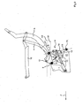
- Fig. 2
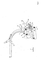
- eine herausgezeichnete Einzeldarstellung etwa des Details II in Fig. 1 in seitlicher Ansicht ohne Dachbezug und mit transparenter Karosserie sowie zwei zusätzlichen eingezeichneten horizontalen Hilfslinien für die Stellung der Lager von Hauptsäule und Hauptführungsstange bei geschlossenem Dach,
- Fig. 3
- eine ähnliche Ansicht wie Fig. 2 bei beginnender Dachöffnung durch Einziehen eines Antriebsorgans und Krafteinwirkung auf die Hauptsäule und einen um ein festes Hauptlager schwenkbaren Hebel,
- Fig. 4 bis Fig. 11
- den weiteren Ablauf der fortschreitenden Dachöffnung in ähnlicher Ansicht wie in Fig. 3,
- Fig. 12
- eine ähnliche Ansicht wie Fig. 2 mit zusätzlich eingezeichneten Bahnkurven der Lager der Hauptsäule und der Hauptführungsstange während der Dachöffnungsbewegung,
- Fig. 13
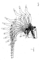
- eine Überlagerung der Ansichten aus den
Figuren 2 bis 11 während des Dachöffnens oder -schließens.
- Fig. 1
- a perspective view of a convertible vehicle according to the invention obliquely from behind with the roof closed,
- Fig. 2
- an isolated detail of about the detail II in Figure 1 in a side view without roof cover and with transparent body and two additional drawn horizontal auxiliary lines for the position of the bearings of the main column and main guide rod with the roof closed.
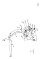
- Fig. 3
- a view similar to FIG. 2 at the beginning of roof opening by pulling a drive member and force on the main column and a pivotable about a fixed main bearing lever,
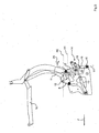
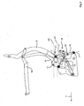
- Fig. 4 to Fig. 11
- the further course of the progressive roof opening in a similar view as in Fig. 3,
- Fig. 12
- a view similar to FIG. 2 with additionally marked trajectories of the bearings of the main column and the main guide bar during the roof opening movement,
- Fig. 13
- a superposition of the views of Figures 2 to 11 during roof opening or closing.
Das erfindungsgemäße Cabriolet-Fahrzeug 1 umfasst im hier dargestellten Ausführungsbeispiel ein außerhalb einer Heckscheibe vollständig von einem Bezug 3 übergriffenes Dach 2, wobei alternativ auch Lösungen mit nur einem Teilbezug und zum Beispiel teilweise starren Dachteilen möglich sind. Auch kann die Dachform variieren und zum Beispiel nach hinten auslaufende seitliche Finnen oder oberhalb von Seitenfenstern 4 separate Rahmen vorsehen. Auch kann innerhalb des Daches 2 ein Schiebe- oder Aufstellbereich vorgesehen sein.The convertible vehicle 1 according to the invention comprises, in the exemplary embodiment illustrated here, a
Das erfindungsgemäße Cabriolet-Fahrzeug 1 kann sowohl ein Zweisitzer sein als auch insbesondere einen größeren Insassenraum mit zwei oder mehr Sitzreihen hintereinander umfassen.The convertible vehicle 1 according to the invention can be both a two-seater and, in particular, comprise a larger passenger compartment with two or more rows of seats one behind the other.
In jedem Fall umfasst das Dach 2 an jeder Querseite des Fahrzeugs 1 eine im Bereich an oder unterhalb einer seitlichen Fensterbrüstungslinie 5 beginnende und sich bei geschlossenem Dach 2 aufwärts - häufig mit einer zusätzlichen Komponente in Fahrtrichtung F - erstreckende Hauptsäule 6, die einen Lenker für die Dachbewegung darstellt.In any case, the
Diese Hauptsäule 6 ist an einem bei geschlossenem Dach 2 unterhalb der Fensterbrüstungslinie 5 gelegenen Lager 7 schwenkbar gehalten. Dieses Lager 7 ist erfindungsgemäß nicht karosseriefest, sondern hier beispielhaft an einem beweglichen Lenker 8 angeordnet. Dieser ist seinerseits beweglich - im gezeichneten Ausführungsbeispiel schwenkbar
- an einem
karosseriefesten Hauptlager 9 gehalten. Auch ein Verschieben desLagers 7 in einer Kulisse oder die Anordnung desLagers 7 an einem während der Dachöffnung separat ausfahrbaren Hubzylinder oder eine sonstige Bewegungsmöglichkeit wären alternativ zu seiner Anordnung an demschwenkbaren Hebel 8 möglich. In jedem Fall ist während des Dachöffnens oder -schließens dasLager 7 mit einer aufwärtsgerichteten Bewegungskomponente aus seiner auf der Hilfslinie H1 befindlichen Ruhestellung anhebbar.
- held on a body-fixed
main bearing 9. Also, a displacement of thebearing 7 in a backdrop or the arrangement of thebearing 7 at a separately extendable during the roof opening lifting cylinder or other movement possibility would be possible as an alternative to its arrangement on the pivotinglever 8. In any case, during roof opening or closing, thebearing 7 can be raised with an upward movement component from its rest position located on the auxiliary line H1.
Nach oben hin erstreckt sich die Hauptsäule 6 bis in den ungefähr horizontalen Bereich des Daches 2. Dort kann an der Hauptsäule 6 zumindest ein weiterer, das Dach 2 nach vorne verlängernder seitlicher Dachrahmen 10 beweglich gehalten sein.Towards the top, the
Die Hauptsäule 6 kann zudem an ihrer in Fahrtrichtung vorderen Kante mit einer hier nicht näher eingezeichneten Dichtungslinie zu den Seitenscheiben 4 versehen sein und punktuelle oder linienhafte Anbindungen für den Bezugsstoff 3 umfassen.The
Neben der Hauptsäule 6 ist hier als weiterer Lenker für die Dachabstützung und -bewegung eine Hauptführungsstange 11 vorgesehen, die sich ebenfalls zwischen der Fensterbrüstungslinie 5 und dem oberen Horizontalbereich des Daches 2 erstreckt. Diese Hauptführungsstange 11 ist an einem Lager 12 gehalten, das ebenfalls gegenüber der Karosserie beweglich gehalten sein kann. Im hier gezeichneten Ausführungsbeispiel ist das Lager 12 zusammen mit dem Lager 7 an dem Schwenkhebel 8 gehalten und somit bei dessen Schwenken um das karosseriefeste Hauptlager 9 aus seiner auf der Hilfslinie H2 gelegenen Ruhestellung mit einer aufwärtsgerichteten Komponente anhebbar.In addition to the
Hauptsäule 6 und Hauptführungsstange 11 wirken nach Art eines Schwenkparallelogramms, das sich bei der Dachöffnung zunächst ebenfalls öffnet, auf das Dach 2 ein.
Für die Dachbewegung ist an jeder Seite ein Antrieb, hier ein Hydraulikzylinder 13, vorgesehen, der über ein kraftverstärkendes und -umlenkendes Vorgelegegetriebe 14 auf die Hauptsäule 6 in zweierlei Bewegungssinnen, nämlich einerseits drehend und andererseits anhebend, einwirkt. Das Vorgelegegetriebe 14 umfasst zwischen dem beweglichen Lager 7 und einem karosseriefesten Lager 15 zwei Lenker 16, 17, die bei geschlossenem Dach 2 im Gelenk 18 unter einem stumpfen Winkel rechts der Verbindungslinie V1 zwischen den Lagern 7, 15 zueinander stehen, während der Dachöffnung in eine geradlinige Parallelstellung zueinander auf der Verbindungslinie V1 gelangen und im weiteren zur anderen Seite dieser Linie V1 durchschwenken und dann dort überstumpf abgewinkelt zueinander stehen. Mit dem Strecken der Lenker 16, 17 zueinander während der Bewegung ist ein Anheben des Lagers 7 verbunden, so dass dieses zumindest während eines Teils der Bewegung des Daches 2 gegenüber seiner Ruhestellung auf der Hilfslinie H1 aufwärts verlagert ist.For the roof movement, a drive, here a
Zum Öffnen des Daches 2 aus der geschlossenen Stellung nach Fig. 2 wird der Hubkolben des Antriebsorgans 13 eingefahren, so dass über das Vorgelegegetriebe 14 die schon beschriebene Winkelvergrößerung im Gelenk 18 zwischen den Lenkern 16, 17 einsetzt und dadurch direkt mit beginnender Dachöffnung (Übergang von Fig. 2 zu Fig. 3) ein Anheben des an dem Lenker 17 angeordneten Lagers 7 zwangsweise und ohne weitere Steuerungselemente stattfindet. Gleichzeitig wird das über das Lager 7 nach unten ragende Ende 19 der Hauptsäule 6 in Richtung des Pfeils 20 mit einer Komponente in Fahrtrichtung F nach vorne verlagert, so dass das Schwenken der Hauptsäule 6 um die Lagerstelle 7 in Richtung des Pfeils 21 zeitgleich einsetzt.To open the
Durch die Aufwärtsverlagerung des Lagers 7 wird auch der am Gelenk 9 an der Karosserie angebundene Schwenklenker 8 in Richtung des Pfeils 22 verschwenkt und nimmt dabei auch das Lager 12 der Hauptführungssäule 11 mit, so dass auch dieses Lager gegenüber der geschlossenen Dachstellung bei der beginnenden Dachöffnung von der Hilfslinie H2 aufwärts verlagert wird. Diese Aufwärtsverlagerung fällt hier kleiner aus als die Aufwärtsverlagerung des Lagers 7 der Hauptführungsstange 6, kann aber eine besonders vorteilhafte Bewegungsbahn des Daches 2 mit seinem Anheben über Hindernisse sicherstellen.Due to the upward displacement of the
In der Stellung nach Fig. 6 stehen die Lenker 16 und 17 in ihrer gestreckten 180°-Stellung zueinander, wodurch das am Lenker 17 gehaltene Lager 7 - ebenso wie das Lager 12 - hier seinen höchsten Punkt innerhalb der Bewegung erreicht und von da an wieder absinkt, ehe es bei geöffnetem Dach wieder auf Ausgangshöhe, angedeutet durch die Hilfslinie H1, liegt (Fig. 11). Bei vollständig geschlossenem und vollständig offenem Dach 2 sind die Positionen der Lager 7 und 12 jeweils gleich, wie dies auch karosseriefesten Lagern entsprechen würde. Die Aufwärtsverlagerung der Lager 7, 12 findet daher nur bei ablaufender Bewegung statt.In the position shown in FIG. 6, the
Beim Öffnen und Schließen des Daches werden von beiden beweglichen Lagern 7, 12 jeweils die gleichen Bahnkurven, nur in gegensinniger Richtung, durchlaufen. Diese Bahnkurven 23, 24 sind in Fig. 12 angedeutet und auch in der überlagerten Darstellung der Gesamtbewegung nach Fig. 13 erkennbar.When opening and closing the roof of both
Die Ablagebewegung ist somit in jedem Fall eine überlagerte mit einer Schwenkkomponente um das Lager 7 und mit dessen Auf- und Abbewegung mit translatorischen und rotatorischen Anteilen. Auch das Lager 7 an sich muss kein reines Schwenklager sein.The depositing movement is thus in each case a superimposed with a pivoting component about the
Das gesamte bewegliche Dach 2 kann vor Einbau in den Rohbau auf Funktion getestet werden; die so fertig eingestellte modulare Einheit kann dann an den Rohbau angeliefert und montiert werden.The entire
Die Erfindung ist zudem sowohl bei Fahrzeugen mit voll- oder teilautomatisch zu bewegenden Dächern, wie hier dargestellt, als auch bei manueller Beweglichkeit des Daches 2 anwendbar.The invention is also applicable both in vehicles with fully or partially automatically moving roofs, as shown here, as well as manual mobility of the
Claims (13)
dadurch gekennzeichnet,
dass das Lager (7) zumindest während eines Teils der Dachöffnungsbewegung gegenüber der geschlossenen Stellung aufwärts verlagert ist.Convertible vehicle (1) having a movable roof (2) comprising a main pillar (6) rising up from a window sill line (5) and movable roof-wise around a bearing (7) upwards and downwards,
characterized,
in that the bearing (7) is displaced upwards, at least during part of the roof opening movement, in relation to the closed position.
dadurch gekennzeichnet,
dass die Hauptsäule (6) mit einer Dichtungslinie zur Abdichtung des geschlossenen Daches (2) gegenüber seitlichen Scheiben (4) versehen ist.Convertible vehicle (1) according to claim 1,
characterized,
that the main column (6) having a sealing line for the sealing of the closed roof (2) opposite side plates (4) is provided.
dadurch gekennzeichnet,
dass dem Fahrzeug neben der Hauptsäule (6) eine Hauptführungsstange (11) zwischen Dach (2) und Karosserie zugeordnet ist.Convertible vehicle (1) according to one of claims 1 or 2,
characterized,
in that, in addition to the main pillar (6), a main guide rod (11) between the roof (2) and the body is assigned to the vehicle.
dadurch gekennzeichnet,
dass die Hauptführungsstange (11) an einem Lager (12) gehalten ist, das zumindest während eines Teils der Dachöffnungsbewegung gegenüber der geschlossenen Stellung aufwärts verlagert ist.Convertible vehicle (1) according to claim 3,
characterized,
in that the main guide rod (11) is held on a bearing (12) displaced upwards, at least during part of the roof opening movement, from the closed position.
dadurch gekennzeichnet,
dass das Lager (12) der Hauptführungsstange (11) und das Lager (7) der Hauptsäule (6) an einem gemeinsamen Hebel (8) gehalten sind, der gegenüber einem karosseriefesten Hauptlager (9) während der Dachöffnung beweglich ist.Convertible vehicle (1) according to claim 4,
characterized,
that the bearing (12) of the main guide rod (11) and the bearing (7) of the main column (6) on a common lever (8) are held, which is opposite a body-mounted main bearing (9) during the roof opening movable.
dadurch gekennzeichnet,
dass der gemeinsame Hebel (8) gegenüber dem Hauptlager (9) schwenkbeweglich ist.Convertible vehicle (1) according to claim 5,
characterized,
in that the common lever (8) is pivotable relative to the main bearing (9).
dadurch gekennzeichnet,
dass die Hauptführungsstange (11) und die Hauptsäule (6) nach Art eines Schwenkparallelogramms auf das Dach einwirken.Convertible vehicle (1) according to one of claims 3 to 6,
characterized,
in that the main guide rod (11) and the main column (6) act on the roof in the manner of a pivot parallelogram.
dadurch gekennzeichnet,
dass die Aufwärtsverlagerung zumindest des Lagers (7) der Hauptsäule (6) mittels eines von einem Antrieb (13) ansteuerbaren Vorgelegegetriebes (14) bewirkbar ist.Convertible vehicle (1) according to one of claims 1 to 7,
characterized,
that the upward displacement of at least the bearing (7) is effected of the main column (6) by means of a by a drive (13) controllable countershaft transmission (14).
dadurch gekennzeichnet,
dass das Lager (7) der Hauptsäule (6) in geöffneter Dachstellung in derselben Position wie in geschlossener Dachstellung liegt.Convertible vehicle (1) according to one of claims 1 to 8,
characterized,
that the bearing (7) of the main column (6) in the open roof position in the same position as in the closed roof position.
dadurch gekennzeichnet,
dass das Lager (12) der Hauptführungsstange (11) in geöffneter Dachstellung in derselben Position wie in geschlossener Dachstellung liegt.Convertible vehicle (1) according to claim 9,
characterized,
that the bearing (12) of the main guide rod (11) in the open roof position in the same position as in closed roof position.
dadurch gekennzeichnet,
dass die Aufwärtsverlagerung des oder der Lager (7;12) mit beginnender Dachöffnung einsetzt und mit dieser zwangsgekoppelt ist.Convertible vehicle (1) according to one of claims 1 to 10,
characterized,
in that the upward displacement of the bearing or bearings (7; 12) begins with the opening of the roof and is forcibly coupled with it.
dadurch gekennzeichnet,
dass von dem oder den Lager(n) (7;12) beim Schließen des Daches (2) die gleiche(n) Bahnkurve(n) (23;24) gegensinnig durchlaufen wird oder werden.Convertible vehicle (1) according to one of claims 1 to 11,
characterized,
in that , when the roof (2) is closed, the same orbit (s) (23; 24) of the bearing (s) (7; 12) are / are passed through in opposite directions.
Applications Claiming Priority (1)
| Application Number | Priority Date | Filing Date | Title |
|---|---|---|---|
| DE102006009548A DE102006009548A1 (en) | 2006-02-28 | 2006-02-28 | Convertible vehicle with a main pillar |
Publications (2)
| Publication Number | Publication Date |
|---|---|
| EP1826048A1 true EP1826048A1 (en) | 2007-08-29 |
| EP1826048B1 EP1826048B1 (en) | 2012-06-27 |
Family
ID=38068686
Family Applications (1)
| Application Number | Title | Priority Date | Filing Date |
|---|---|---|---|
| EP07002252A Not-in-force EP1826048B1 (en) | 2006-02-28 | 2007-02-02 | Convertible vehicle with a main column |
Country Status (3)
| Country | Link |
|---|---|
| US (1) | US7654606B2 (en) |
| EP (1) | EP1826048B1 (en) |
| DE (1) | DE102006009548A1 (en) |
Cited By (2)
| Publication number | Priority date | Publication date | Assignee | Title |
|---|---|---|---|---|
| WO2010105037A1 (en) * | 2009-03-12 | 2010-09-16 | Wilhelm Karmann Gmbh | Z-fold convertible top with two piece side rail |
| FR2959699A1 (en) * | 2010-05-07 | 2011-11-11 | Peugeot Citroen Automobiles Sa | Flexible roof for e.g. drophead, has fabric fixed with movable structure by fixation points that are slidably movable in guided and controlled manner, along respective front lateral posts to stretch fabric to closed position |
Families Citing this family (7)
| Publication number | Priority date | Publication date | Assignee | Title |
|---|---|---|---|---|
| DE102005036243A1 (en) * | 2005-08-02 | 2007-02-08 | Wilhelm Karmann Gmbh | Production of convertible roofs |
| DE102007055043B4 (en) | 2007-11-19 | 2009-12-31 | Webasto Ag | Convertible car |
| DE102009009596B4 (en) * | 2009-02-19 | 2014-07-10 | Webasto-Edscha Cabrio GmbH | Hood for a convertible vehicle |
| DE102009052186B4 (en) * | 2009-11-06 | 2016-07-07 | Audi Ag | Convertible vehicle with a roof system connected to the bodywork |
| DE102011016781A1 (en) | 2011-04-12 | 2012-10-18 | Magna Car Top Systems Gmbh | Drive for a C-pillar |
| DE102012203234A1 (en) * | 2012-03-01 | 2013-09-05 | Bayerische Motoren Werke Aktiengesellschaft | Movable collapsible and/or stowable vehicle roof for motor vehicle e.g. cabriolet, has multi-joint mechanism that is movably mounted on main bearing located below vehicle seat, such that position of main bearing can be changed |
| US10220689B2 (en) * | 2017-06-30 | 2019-03-05 | Webasto SE | Top of a vehicle comprising locking means |
Citations (3)
| Publication number | Priority date | Publication date | Assignee | Title |
|---|---|---|---|---|
| US5785375A (en) | 1993-12-29 | 1998-07-28 | Asc Incorporated | Retractable hard-top for an automotive vehicle |
| DE19706398A1 (en) | 1997-02-19 | 1998-08-20 | Daimler Benz Ag | Hard top for a convertible |
| US20040051341A1 (en) | 2002-09-18 | 2004-03-18 | Willard Michael T. | Vehicle retractable hardtop roof |
Family Cites Families (16)
| Publication number | Priority date | Publication date | Assignee | Title |
|---|---|---|---|---|
| US3539173A (en) * | 1968-05-23 | 1970-11-10 | Byron Jackson Inc | Bumper |
| DE19706417C1 (en) * | 1997-02-19 | 1998-07-09 | Daimler Benz Ag | Collapsible hood for convertible motor vehicle |
| NL1006558C2 (en) * | 1997-07-11 | 1999-01-12 | Applied Power Inc | Folding roof assembly for a vehicle and vehicle provided with such a folding roof assembly. |
| DE19815960A1 (en) | 1998-04-09 | 1999-10-14 | Bosch Gmbh Robert | Method and device for controlling a sunroof device |
| DE19815980A1 (en) * | 1998-04-09 | 1999-10-21 | Edscha Cabrio Verdecksys Gmbh | Folding top for convertible vehicles |
| DE19912357C1 (en) * | 1999-03-19 | 2000-11-02 | Karmann Gmbh W | Cabriolet vehicle |
| DE29909513U1 (en) * | 1999-05-31 | 1999-09-02 | Edscha Cabrio Verdecksys Gmbh | Folding roof for passenger cars |
| NL1013743C2 (en) * | 1999-12-03 | 2001-06-06 | Applied Power Inc | Drive assembly for a movable vehicle part. |
| DE19963149B4 (en) * | 1999-12-24 | 2004-11-04 | Wilhelm Karmann Gmbh | Cabriolet vehicle with a fold-out roof |
| DE29923087U1 (en) * | 1999-12-31 | 2001-05-10 | Karmann Gmbh W | Folding top for a convertible vehicle |
| JP3524524B2 (en) * | 2001-07-10 | 2004-05-10 | 本田技研工業株式会社 | Convertible hardtop storage structure |
| DE20210763U1 (en) * | 2002-07-17 | 2003-11-27 | Wilhelm Karmann Gmbh | Convertible car |
| US6692061B1 (en) * | 2003-02-06 | 2004-02-17 | Asc Incorporated | Vehicle convertible roof |
| DE10340233B4 (en) * | 2003-08-29 | 2006-11-09 | Webasto Ag | Folding hood for a motor vehicle |
| DE10349820A1 (en) | 2003-10-24 | 2005-06-02 | Wilhelm Karmann Gmbh | Convertible car |
| US7243983B2 (en) * | 2005-02-23 | 2007-07-17 | Asc Incorporated | Retractable pillar for convertible vehicle |
-
2006
- 2006-02-28 DE DE102006009548A patent/DE102006009548A1/en not_active Withdrawn
-
2007
- 2007-02-02 EP EP07002252A patent/EP1826048B1/en not_active Not-in-force
- 2007-02-28 US US11/712,275 patent/US7654606B2/en not_active Expired - Fee Related
Patent Citations (3)
| Publication number | Priority date | Publication date | Assignee | Title |
|---|---|---|---|---|
| US5785375A (en) | 1993-12-29 | 1998-07-28 | Asc Incorporated | Retractable hard-top for an automotive vehicle |
| DE19706398A1 (en) | 1997-02-19 | 1998-08-20 | Daimler Benz Ag | Hard top for a convertible |
| US20040051341A1 (en) | 2002-09-18 | 2004-03-18 | Willard Michael T. | Vehicle retractable hardtop roof |
Cited By (2)
| Publication number | Priority date | Publication date | Assignee | Title |
|---|---|---|---|---|
| WO2010105037A1 (en) * | 2009-03-12 | 2010-09-16 | Wilhelm Karmann Gmbh | Z-fold convertible top with two piece side rail |
| FR2959699A1 (en) * | 2010-05-07 | 2011-11-11 | Peugeot Citroen Automobiles Sa | Flexible roof for e.g. drophead, has fabric fixed with movable structure by fixation points that are slidably movable in guided and controlled manner, along respective front lateral posts to stretch fabric to closed position |
Also Published As
| Publication number | Publication date |
|---|---|
| US7654606B2 (en) | 2010-02-02 |
| DE102006009548A1 (en) | 2007-08-30 |
| US20070216191A1 (en) | 2007-09-20 |
| EP1826048B1 (en) | 2012-06-27 |
Similar Documents
| Publication | Publication Date | Title |
|---|---|---|
| EP1826048B1 (en) | Convertible vehicle with a main column | |
| DE10050286A1 (en) | Multi-part cover for vehicles | |
| EP1900562B1 (en) | Convertible vehicle with a roof composed of several parts | |
| EP1971501B1 (en) | Folding top for a motor vehicle | |
| DE10248344A1 (en) | motor vehicle | |
| DE10326981B4 (en) | Vehicle convertible from a pickup to a convertible | |
| DE10218241C1 (en) | Automobile cabriolet roof has opening roof section provided with relatively pivoted column elements fitting either side of rear windscreen element | |
| EP1554143B1 (en) | Cabriolet vehicle | |
| DE10224834A1 (en) | Convertible car | |
| EP1588881B1 (en) | Vehicle with movable roof parts | |
| EP2004432B1 (en) | Hardtop folding roof for an open motor vehicle | |
| EP1902882B1 (en) | Motor vehicle with a hatchback and at least one roof section stretching across the width of the retractable roof | |
| DE102004025051B4 (en) | Adjustable hardtop vehicle roof has adjustment device held at rear portion of roof for moving and adjusting back window with front and rear portions and side supports between open and closed positions | |
| AT503686B1 (en) | CABRIOLET VEHICLE WITH A CONDITION LIMITED TO SIDE FRAME COMPONENTS | |
| EP1554144A2 (en) | Motor vehicle | |
| EP1916139A1 (en) | Motor vehicle with a foldable soft top, stowable in a roof storage compartment | |
| DE102013108730B4 (en) | Cabriolet rear window with support lever | |
| DE102007060363B4 (en) | Motor vehicle with a rear window comprehensive unit | |
| DE10155887A1 (en) | Convertible motor car has hardtop pivot mechanism consisting of first lever formed by C-columns, and second lever formed by rear window frame to act as balance link | |
| DE10228006B4 (en) | motor vehicle | |
| EP1737690B1 (en) | Convertible | |
| DE10248350A1 (en) | Convertible motor vehicle has upper roof section comprising transparent panel which is movable opposite direction of travel like sliding roof and in opened position supported parallel to rear windscreen within rear roof section | |
| DE102005009719A1 (en) | Device for drive component adjustably between two different end position has stop element, mounted at first arm of rocker arm which is pivoted around fulcrum whereby connecting rod is fitted in first end position of drive kinematics | |
| DE102006054394A1 (en) | Cabriolet vehicle with a towering pillar part of the roof | |
| DE102006010395A1 (en) | Convertible vehicle with at least two rigid roof parts |
Legal Events
| Date | Code | Title | Description |
|---|---|---|---|
| PUAI | Public reference made under article 153(3) epc to a published international application that has entered the european phase |
Free format text: ORIGINAL CODE: 0009012 |
|
| AK | Designated contracting states |
Kind code of ref document: A1 Designated state(s): AT BE BG CH CY CZ DE DK EE ES FI FR GB GR HU IE IS IT LI LT LU LV MC NL PL PT RO SE SI SK TR |
|
| AX | Request for extension of the european patent |
Extension state: AL BA HR MK YU |
|
| 17P | Request for examination filed |
Effective date: 20070920 |
|
| 17Q | First examination report despatched |
Effective date: 20071213 |
|
| AKX | Designation fees paid |
Designated state(s): AT BE BG CH CY CZ DE DK EE ES FI FR GB GR HU IE IS IT LI LT LU LV MC NL PL PT RO SE SI SK TR |
|
| 19U | Interruption of proceedings before grant |
Effective date: 20090629 |
|
| 19W | Proceedings resumed before grant after interruption of proceedings |
Effective date: 20101201 |
|
| GRAP | Despatch of communication of intention to grant a patent |
Free format text: ORIGINAL CODE: EPIDOSNIGR1 |
|
| GRAS | Grant fee paid |
Free format text: ORIGINAL CODE: EPIDOSNIGR3 |
|
| GRAA | (expected) grant |
Free format text: ORIGINAL CODE: 0009210 |
|
| AK | Designated contracting states |
Kind code of ref document: B1 Designated state(s): AT BE BG CH CY CZ DE DK EE ES FI FR GB GR HU IE IS IT LI LT LU LV MC NL PL PT RO SE SI SK TR |
|
| REG | Reference to a national code |
Ref country code: GB Ref legal event code: FG4D Free format text: NOT ENGLISH |
|
| REG | Reference to a national code |
Ref country code: CH Ref legal event code: EP |
|
| REG | Reference to a national code |
Ref country code: AT Ref legal event code: REF Ref document number: 563970 Country of ref document: AT Kind code of ref document: T Effective date: 20120715 |
|
| REG | Reference to a national code |
Ref country code: IE Ref legal event code: FG4D Free format text: LANGUAGE OF EP DOCUMENT: GERMAN |
|
| REG | Reference to a national code |
Ref country code: DE Ref legal event code: R096 Ref document number: 502007010084 Country of ref document: DE Effective date: 20120830 |
|
| PG25 | Lapsed in a contracting state [announced via postgrant information from national office to epo] |
Ref country code: SE Free format text: LAPSE BECAUSE OF FAILURE TO SUBMIT A TRANSLATION OF THE DESCRIPTION OR TO PAY THE FEE WITHIN THE PRESCRIBED TIME-LIMIT Effective date: 20120627 Ref country code: FI Free format text: LAPSE BECAUSE OF FAILURE TO SUBMIT A TRANSLATION OF THE DESCRIPTION OR TO PAY THE FEE WITHIN THE PRESCRIBED TIME-LIMIT Effective date: 20120627 Ref country code: LT Free format text: LAPSE BECAUSE OF FAILURE TO SUBMIT A TRANSLATION OF THE DESCRIPTION OR TO PAY THE FEE WITHIN THE PRESCRIBED TIME-LIMIT Effective date: 20120627 |
|
| REG | Reference to a national code |
Ref country code: NL Ref legal event code: VDEP Effective date: 20120627 |
|
| REG | Reference to a national code |
Ref country code: LT Ref legal event code: MG4D Effective date: 20120627 |
|
| PG25 | Lapsed in a contracting state [announced via postgrant information from national office to epo] |
Ref country code: GR Free format text: LAPSE BECAUSE OF FAILURE TO SUBMIT A TRANSLATION OF THE DESCRIPTION OR TO PAY THE FEE WITHIN THE PRESCRIBED TIME-LIMIT Effective date: 20120928 Ref country code: LV Free format text: LAPSE BECAUSE OF FAILURE TO SUBMIT A TRANSLATION OF THE DESCRIPTION OR TO PAY THE FEE WITHIN THE PRESCRIBED TIME-LIMIT Effective date: 20120627 Ref country code: SI Free format text: LAPSE BECAUSE OF FAILURE TO SUBMIT A TRANSLATION OF THE DESCRIPTION OR TO PAY THE FEE WITHIN THE PRESCRIBED TIME-LIMIT Effective date: 20120627 |
|
| PG25 | Lapsed in a contracting state [announced via postgrant information from national office to epo] |
Ref country code: EE Free format text: LAPSE BECAUSE OF FAILURE TO SUBMIT A TRANSLATION OF THE DESCRIPTION OR TO PAY THE FEE WITHIN THE PRESCRIBED TIME-LIMIT Effective date: 20120627 Ref country code: SK Free format text: LAPSE BECAUSE OF FAILURE TO SUBMIT A TRANSLATION OF THE DESCRIPTION OR TO PAY THE FEE WITHIN THE PRESCRIBED TIME-LIMIT Effective date: 20120627 Ref country code: IS Free format text: LAPSE BECAUSE OF FAILURE TO SUBMIT A TRANSLATION OF THE DESCRIPTION OR TO PAY THE FEE WITHIN THE PRESCRIBED TIME-LIMIT Effective date: 20121027 Ref country code: RO Free format text: LAPSE BECAUSE OF FAILURE TO SUBMIT A TRANSLATION OF THE DESCRIPTION OR TO PAY THE FEE WITHIN THE PRESCRIBED TIME-LIMIT Effective date: 20120627 Ref country code: CY Free format text: LAPSE BECAUSE OF FAILURE TO SUBMIT A TRANSLATION OF THE DESCRIPTION OR TO PAY THE FEE WITHIN THE PRESCRIBED TIME-LIMIT Effective date: 20120627 Ref country code: CZ Free format text: LAPSE BECAUSE OF FAILURE TO SUBMIT A TRANSLATION OF THE DESCRIPTION OR TO PAY THE FEE WITHIN THE PRESCRIBED TIME-LIMIT Effective date: 20120627 |
|
| PG25 | Lapsed in a contracting state [announced via postgrant information from national office to epo] |
Ref country code: PL Free format text: LAPSE BECAUSE OF FAILURE TO SUBMIT A TRANSLATION OF THE DESCRIPTION OR TO PAY THE FEE WITHIN THE PRESCRIBED TIME-LIMIT Effective date: 20120627 Ref country code: PT Free format text: LAPSE BECAUSE OF FAILURE TO SUBMIT A TRANSLATION OF THE DESCRIPTION OR TO PAY THE FEE WITHIN THE PRESCRIBED TIME-LIMIT Effective date: 20121029 Ref country code: IT Free format text: LAPSE BECAUSE OF FAILURE TO SUBMIT A TRANSLATION OF THE DESCRIPTION OR TO PAY THE FEE WITHIN THE PRESCRIBED TIME-LIMIT Effective date: 20120627 |
|
| PG25 | Lapsed in a contracting state [announced via postgrant information from national office to epo] |
Ref country code: NL Free format text: LAPSE BECAUSE OF FAILURE TO SUBMIT A TRANSLATION OF THE DESCRIPTION OR TO PAY THE FEE WITHIN THE PRESCRIBED TIME-LIMIT Effective date: 20120627 |
|
| PG25 | Lapsed in a contracting state [announced via postgrant information from national office to epo] |
Ref country code: DK Free format text: LAPSE BECAUSE OF FAILURE TO SUBMIT A TRANSLATION OF THE DESCRIPTION OR TO PAY THE FEE WITHIN THE PRESCRIBED TIME-LIMIT Effective date: 20120627 Ref country code: ES Free format text: LAPSE BECAUSE OF FAILURE TO SUBMIT A TRANSLATION OF THE DESCRIPTION OR TO PAY THE FEE WITHIN THE PRESCRIBED TIME-LIMIT Effective date: 20121008 |
|
| PLBE | No opposition filed within time limit |
Free format text: ORIGINAL CODE: 0009261 |
|
| STAA | Information on the status of an ep patent application or granted ep patent |
Free format text: STATUS: NO OPPOSITION FILED WITHIN TIME LIMIT |
|
| 26N | No opposition filed |
Effective date: 20130328 |
|
| REG | Reference to a national code |
Ref country code: DE Ref legal event code: R097 Ref document number: 502007010084 Country of ref document: DE Effective date: 20130328 |
|
| PG25 | Lapsed in a contracting state [announced via postgrant information from national office to epo] |
Ref country code: BG Free format text: LAPSE BECAUSE OF FAILURE TO SUBMIT A TRANSLATION OF THE DESCRIPTION OR TO PAY THE FEE WITHIN THE PRESCRIBED TIME-LIMIT Effective date: 20120927 |
|
| BERE | Be: lapsed |
Owner name: WILHELM KARMANN G.M.B.H. Effective date: 20130228 |
|
| PG25 | Lapsed in a contracting state [announced via postgrant information from national office to epo] |
Ref country code: MC Free format text: LAPSE BECAUSE OF NON-PAYMENT OF DUE FEES Effective date: 20130228 |
|
| REG | Reference to a national code |
Ref country code: CH Ref legal event code: PL |
|
| PG25 | Lapsed in a contracting state [announced via postgrant information from national office to epo] |
Ref country code: CH Free format text: LAPSE BECAUSE OF NON-PAYMENT OF DUE FEES Effective date: 20130228 Ref country code: LI Free format text: LAPSE BECAUSE OF NON-PAYMENT OF DUE FEES Effective date: 20130228 |
|
| REG | Reference to a national code |
Ref country code: DE Ref legal event code: R082 Ref document number: 502007010084 Country of ref document: DE Representative=s name: KRONTHALER, SCHMIDT & COLL. PATENTANWALTSKANZL, DE |
|
| REG | Reference to a national code |
Ref country code: IE Ref legal event code: MM4A |
|
| REG | Reference to a national code |
Ref country code: GB Ref legal event code: 732E Free format text: REGISTERED BETWEEN 20131114 AND 20131120 |
|
| REG | Reference to a national code |
Ref country code: FR Ref legal event code: TP Owner name: VALMET AUTOMOTIVE OY, FI Effective date: 20131209 |
|
| REG | Reference to a national code |
Ref country code: DE Ref legal event code: R082 Ref document number: 502007010084 Country of ref document: DE Representative=s name: KRONTHALER, SCHMIDT & COLL. PATENTANWALTSKANZL, DE Effective date: 20131202 Ref country code: DE Ref legal event code: R081 Ref document number: 502007010084 Country of ref document: DE Owner name: VALMET AUTOMOTIVE OY, FI Free format text: FORMER OWNER: WILHELM KARMANN GMBH, 49084 OSNABRUECK, DE Effective date: 20131202 Ref country code: DE Ref legal event code: R081 Ref document number: 502007010084 Country of ref document: DE Owner name: VALMET AUTOMOTIVE OY, FI Free format text: FORMER OWNER: WILHELM KARMANN GMBH, 49084 OSNABRUECK, DE Effective date: 20120709 |
|
| PG25 | Lapsed in a contracting state [announced via postgrant information from national office to epo] |
Ref country code: IE Free format text: LAPSE BECAUSE OF NON-PAYMENT OF DUE FEES Effective date: 20130202 Ref country code: BE Free format text: LAPSE BECAUSE OF NON-PAYMENT OF DUE FEES Effective date: 20130228 |
|
| REG | Reference to a national code |
Ref country code: AT Ref legal event code: MM01 Ref document number: 563970 Country of ref document: AT Kind code of ref document: T Effective date: 20130202 |
|
| PG25 | Lapsed in a contracting state [announced via postgrant information from national office to epo] |
Ref country code: AT Free format text: LAPSE BECAUSE OF NON-PAYMENT OF DUE FEES Effective date: 20130202 |
|
| PG25 | Lapsed in a contracting state [announced via postgrant information from national office to epo] |
Ref country code: TR Free format text: LAPSE BECAUSE OF FAILURE TO SUBMIT A TRANSLATION OF THE DESCRIPTION OR TO PAY THE FEE WITHIN THE PRESCRIBED TIME-LIMIT Effective date: 20120627 |
|
| PG25 | Lapsed in a contracting state [announced via postgrant information from national office to epo] |
Ref country code: LU Free format text: LAPSE BECAUSE OF NON-PAYMENT OF DUE FEES Effective date: 20130202 Ref country code: HU Free format text: LAPSE BECAUSE OF FAILURE TO SUBMIT A TRANSLATION OF THE DESCRIPTION OR TO PAY THE FEE WITHIN THE PRESCRIBED TIME-LIMIT; INVALID AB INITIO Effective date: 20070202 |
|
| REG | Reference to a national code |
Ref country code: FR Ref legal event code: PLFP Year of fee payment: 10 |
|
| PGFP | Annual fee paid to national office [announced via postgrant information from national office to epo] |
Ref country code: GB Payment date: 20160428 Year of fee payment: 10 |
|
| REG | Reference to a national code |
Ref country code: FR Ref legal event code: PLFP Year of fee payment: 11 |
|
| GBPC | Gb: european patent ceased through non-payment of renewal fee |
Effective date: 20170202 |
|
| PG25 | Lapsed in a contracting state [announced via postgrant information from national office to epo] |
Ref country code: GB Free format text: LAPSE BECAUSE OF NON-PAYMENT OF DUE FEES Effective date: 20170202 |
|
| REG | Reference to a national code |
Ref country code: FR Ref legal event code: PLFP Year of fee payment: 12 |
|
| PGFP | Annual fee paid to national office [announced via postgrant information from national office to epo] |
Ref country code: FR Payment date: 20220221 Year of fee payment: 16 |
|
| PGFP | Annual fee paid to national office [announced via postgrant information from national office to epo] |
Ref country code: DE Payment date: 20220419 Year of fee payment: 16 |
|
| P01 | Opt-out of the competence of the unified patent court (upc) registered |
Effective date: 20230601 |
|
| REG | Reference to a national code |
Ref country code: DE Ref legal event code: R119 Ref document number: 502007010084 Country of ref document: DE |
|
| PG25 | Lapsed in a contracting state [announced via postgrant information from national office to epo] |
Ref country code: FR Free format text: LAPSE BECAUSE OF NON-PAYMENT OF DUE FEES Effective date: 20230228 Ref country code: DE Free format text: LAPSE BECAUSE OF NON-PAYMENT OF DUE FEES Effective date: 20230901 |