EP1819113B1 - Method for data transmission via data networks - Google Patents
Method for data transmission via data networks Download PDFInfo
- Publication number
- EP1819113B1 EP1819113B1 EP07002172A EP07002172A EP1819113B1 EP 1819113 B1 EP1819113 B1 EP 1819113B1 EP 07002172 A EP07002172 A EP 07002172A EP 07002172 A EP07002172 A EP 07002172A EP 1819113 B1 EP1819113 B1 EP 1819113B1
- Authority
- EP
- European Patent Office
- Prior art keywords
- real
- time
- data
- messages
- communication
- Prior art date
- Legal status (The legal status is an assumption and is not a legal conclusion. Google has not performed a legal analysis and makes no representation as to the accuracy of the status listed.)
- Not-in-force
Links
- 238000000034 method Methods 0.000 title claims abstract description 26
- 230000005540 biological transmission Effects 0.000 title claims abstract description 15
- 238000004891 communication Methods 0.000 claims abstract description 90
- 230000003111 delayed effect Effects 0.000 claims abstract description 7
- 230000002123 temporal effect Effects 0.000 claims description 12
- 239000000203 mixture Substances 0.000 claims description 4
- 230000008878 coupling Effects 0.000 abstract description 45
- 238000010168 coupling process Methods 0.000 abstract description 45
- 238000005859 coupling reaction Methods 0.000 abstract description 45
- 230000006870 function Effects 0.000 description 7
- 230000000712 assembly Effects 0.000 description 4
- 238000000429 assembly Methods 0.000 description 4
- 238000010586 diagram Methods 0.000 description 3
- 238000013475 authorization Methods 0.000 description 2
- 230000007246 mechanism Effects 0.000 description 2
- 230000001419 dependent effect Effects 0.000 description 1
- 238000011161 development Methods 0.000 description 1
- 230000018109 developmental process Effects 0.000 description 1
- 230000000694 effects Effects 0.000 description 1
- 238000011156 evaluation Methods 0.000 description 1
Images


Classifications
-
- H—ELECTRICITY
- H04—ELECTRIC COMMUNICATION TECHNIQUE
- H04L—TRANSMISSION OF DIGITAL INFORMATION, e.g. TELEGRAPHIC COMMUNICATION
- H04L12/00—Data switching networks
- H04L12/64—Hybrid switching systems
- H04L12/6418—Hybrid transport
-
- H—ELECTRICITY
- H04—ELECTRIC COMMUNICATION TECHNIQUE
- H04L—TRANSMISSION OF DIGITAL INFORMATION, e.g. TELEGRAPHIC COMMUNICATION
- H04L12/00—Data switching networks
- H04L12/64—Hybrid switching systems
- H04L12/6418—Hybrid transport
- H04L2012/6445—Admission control
Definitions
- the present invention relates to real-time communication systems, and more particularly to Ethernet-based data networks.
- real-time communication systems known from the prior art
- standard Ethernet subscribers can not be integrated directly into the communication system or standard Ethernet subscribers can not be coupled directly to a real-time communication system.
- the present invention will be described in particular in the field of Ethernet-based communication systems, for which a simple implementation of a coupling module is illustrated.
- a real-time communication system essentially consists of a large number of subscribers.
- the system comprises major subscribers (so-called “masters”) and secondary subscribers (so-called “slaves”).
- data is exchanged in the form of real-time telegrams.
- real-time telegrams their precise position is crucial in order to assemble information correctly.
- data exchange mechanisms that do not run in real time. These mechanisms are used, for example, for commissioning and for display or for diagnostic purposes with low time requirements.
- Real-time communication is understood as a communication in which given activities take place with almost no time delay, ie. H. usually with a guaranteed maximum delay previously known to other systems.
- PCs are generally used that have no direct connection to the real-time communication system. These PCs must be coupled to the system via coupling modules. The coupling of PCs to the communication system takes place, for example, by network participants. It is also common to connect PCs to the "Ethernet (Office)". The coupling function is taken over by individual real-time communication participants.
- US 2002/0064157 A1 shows a method according to the preamble of claim 1.
- the data networks at least have a topological real-time area and a topological non-real-time and sent via the data networks
- data telegrams have at least one real-time part and at least one non-real-time part, according to the invention by a coupling module
- Data telegrams from the non-real-time range which arrive within the real-time part, delayed in time and transferred to the non-real-time part.
- the present invention is particularly related to at least partially repeating data networks. Both pure repeat and mixed repeat and / or switched data networks are conceivable. Preferably, however, the repeater functionality is mandatory.
- a locatable region within the Data network understood.
- a real-time part and a non-real-time part are understood in particular but not exclusively temporal parts.
- the individual real-time or non-real-time parts may also be defined by a position within a communication cycle.
- this non-real-time part is relevant in particular in the real-time domain, i. the area where so-called real-time critical data is transmitted.
- data telegrams are also taken from the non-real-time part (within the topological real-time domain) and transmitted to the non-real-time domain.
- This procedure represents the reverse transmission direction with respect to the above transmission of data telegrams from the non-real-time domain to the real-time domain. It is preferably those data telegrams which are transmitted from the non-real-time domain to the real-time domain and those data telegrams which are transmitted from the real-time domain to the non-real-time domain to different data telegrams, which illustrates that data telegrams can be transmitted bidirectionally.
- data telegrams are also taken from the real-time part (within the real-time range) and transmitted to the non-real-time range.
- a transmission of data telegrams from the real-time domain to the non-real-time domain takes place.
- the data is transmitted in the form of communication cycles, wherein these communication cycles particularly preferably have predetermined periods of time.
- the communication in real-time systems takes place here in the communication cycles, wherein a communication cycle consists essentially of two parts, namely the part of the real-time communication and the part of the non-real-time communication.
- the part of the real-time communication or the real-time part (which is also referred to below as the RT channel) is typically managed by the main subscriber and the transmission authorizations are forgiven by this.
- the data telegrams in this RT channel are preferably repeated by the participants.
- IP channel non-real-time part
- IP channel a time range during which no transmission authorizations are specified.
- each participant can occupy the communication system.
- switch from the repeater function to a switched function for the period of the IP channel switching of the data telegrams in the IP channel.
- the non-real-time part is set changeable within a communication cycle.
- the coupling module determines parameters that are characteristic of the position of at least the non-real-time part within a communication cycle. More precisely, these parameters are learned. Preferably, the parameters are selected from a group of parameters including the start times of the non-real time part, the non-real time part end times, the non-real time part time length, the real time part time length, and the like. In particular, the values for the start time of the non-real time part and the end time of the non-real time part are needed to determine the position of the non-real time part.
- the temporal length of the non-real-time part is also determined.
- the coupling module can close the time range of the IP channel by calculating the permitted range for the IP channel by means of the earliest, the latest reception time and the respective telegram lengths. Since the telegram identifier of the real-time messages (RT channel) deviates from those in the IP channel, the coupling module can distinguish the telegrams in the time domain of the IP channel from those in the RT channel time range. In other words, the position of the non-real-time part is determined by evaluating the reception times of received telegrams.
- the position of the non-real-time part is determined by evaluating the reception times of received data telegrams and particularly preferably of non-real-time telegrams.
- the present invention is further directed to use of a method of the type described above for Ethernet based communication systems.
- the present invention is also directed to use of the method described above for real-time communication systems in general.
- the invention is directed to the use of a method of the kind described above for an at least also repeating network, i. a network in which not only switched (geswitcht) but at least also be repeatedet.
- the invention is also applicable to purely repeating networks.
- the processes presented here are carried out in particular in the lower layers of the OSI reference model.
- the present invention is further directed to a communication device for transmitting data, wherein the communication device comprises at least a first participant and at least one second participant, and a coupling assembly for connecting further participants to the communication device.
- the communication device has at least one topological real-time domain and a topological non-real-time domain, and data telegrams transmitted by the communication apparatus have at least one, in particular temporal, real-time part and one temporal non-real-time part in particular.
- the coupling module has a control device which causes data telegrams from the non-real-time range which arrive within the real-time part in the coupling module to be delayed in time and transmitted to the non-real-time part of a communication cycle. In this way, a disturbing collision with real-time critical data can be prevented.
- the control device preferably causes data telegrams to be taken from a non-real-time part and transmitted to the non-real-time range. This means that here too data telegrams are transferred from the real-time domain into the non-real-time domain.
- the control device also causes data telegrams to be taken from a real-time part and transmitted to the non-real-time range.
- data telegrams can describe individual data telegrams as well as respectively pluralities of data telegrams.
- the coupling module independently determines parameters that are characteristic of the position of the non-real-time part within a communication cycle.
- the present invention is further directed to a coupling assembly for a communication device for transmitting data via in particular Ethernet-based data networks with a plurality of subscribers, which has at least one real-time domain and at least one non-real-time domain.
- the data telegrams transmitted by the communication device contain at least a real-time part and a non-real-time part.
- the coupling module has a control device which causes data telegrams from the non-real-time range which arrive within the temporal real-time part in the coupling module to be delayed in time and inserted into the non-real-time line.
- the present invention is further directed to the use of a coupling assembly as described above for an at least also repeating network.
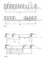
- FIG. 1 shows a block diagram of the structure of a real-time communication system 1, as used in particular in automation applications.
- This system comprises a main participant 3 and a plurality of secondary participants 4, 4a, 4b, 4c. Data is exchanged in the form of real-time telegrams between this main participant and the secondary participants.
- reference numeral 6 refers to a real-time region of the communication system.
- the main subscriber has two lines P1 and P2 for corresponding data lines.
- Sub-participant 4b is an I / O interface in this embodiment.
- the reference numeral 21 refers to a coupling for the (topological) non-real-time area, for example in the form of Ethernet (Office) and the reference numeral 5 refers to a data line.
- FIG. 2 the data flows between the individual participants are shown.
- real-time critical data is exchanged between the main subscriber 3 and the secondary users 4, 4a, 4b and 4c, which is illustrated by the real-time channel 13 (RT channel).
- non-real-time critical data is exchanged via an IP channel 14 between the individual participants. This is the case, for example, if access to the individual subscribers of the communication system, eg. B. is desired by PCs.
- PCs 27 and 28 are used, which have no direct connection to the real-time communication system. These PCs must be coupled to the system via coupling modules. It is known from the prior art that the non-real-time participants marked with 27 and 28 are coupled by network participants to the communication system. Also a coupling of a PC to "Ethernet (Office)" is common. The individual real-time communication participants assume the coupling function. At the in FIG. 3 As shown, the PCs are coupled via the input P1 or the last secondary participant 4c. For coupling, it is necessary for these systems that the individual participants know the time distribution of the respective communication cycles or the positions of the IP and RT channels.
- the in Fig. 3 last participant shown 4c uses its internal bridge function. This ensures that the RT channel is not disturbed by IP data of the telegrams.
- the main subscriber 3 supports the IP data transmission via the input P1.
- FIG. 4 shows a representation of a communication cycle 16.
- this communication cycle 16 a real-time part 13 and a non-real-time part 14, wherein within these parts each data telegrams 11 are arranged.
- the communication cycle 16 has a non-real-time part, which is arranged between two real-time parts 13.
- HDR / MST data fields
- the position of the IP channel or non-real-time part within the communication cycle 16 is defined by a predetermined constant time range. This time range is usually specified by the main participant. It is possible to transmit the location of this IP channel, for example, within an initialization of the main participant to the secondary participant.
- the sub-participants are explicitly transferred the position of the IP channel from the main subscriber as a so-called parameter. Therefore, as mentioned above, the secondary participants must have accessible parameter memory which the main station can describe.
- the times t6 and t7 in FIG. 5 are in contrast to this invention those parameters which describe the position of the IP channel within the communication cycle, since time t6 represents the start time of non-real time part 14 and time t7 the end time of non-real time part 14.
- the time tscyc represents the total time of the communication cycle 16.
- the coupling modules send data telegrams from the non-real-time range which are stored in FIG. 3 is denoted by the reference numeral 7, coupled into the real-time area such that the real-time communication is not disturbed.
- the data must be fed into the IP channel.
- data telegrams from the IP channel and optionally also from the RT channel can be fed into the non-real-time area 7.
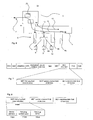
- FIG. 6 shows a communication device according to the invention with a coupling assembly 10.
- a separate coupling assembly also referred to as IP T-Plug
- IP T-Plug the mixture of repeater function and switched Bus communication
- the coupling assembly according to the invention does not represent a network participant with its own network address. It is thus not visible as a node in the communication network, but only transparently routes the data from the non-real-time domain (in FIG. 6 represented as Ethernet switch 4a with three subscribers 8, 9 and 12) in the IP channel in the real-time domain.
- This coupling assembly 10 does not contain any parameters to be set, but determines the necessary parameters, which are, as stated above, at least the parameters t6 and t7, independently.
- the value for the time interval tscyc is determined.
- the coupling module 10 according to the invention is a passive element with respect to the real-time communication.
- This coupling module only processes the IP channel, therefore, as mentioned above, the times t6 and t7 must be evaluated.
- the telegram MDT 0 which must be in FIGS. 4 and 5 is displayed, evaluated.
- An IP telegram should only be fed into one channel (P or S) because of the time delay (ring delay) of the P and S channels, so that the entire device can be implemented more easily.
- FIGS. 7 and 8 describe a self-learning coupling module with content telegram evaluation. If the information about the position of the IP channel at a position known for the coupling module is transmitted in data telegrams within a cyclical channel, the coupling module can determine the temporal position of the IP channel by evaluating the content of the message content.
- the so-called hot-plug field which occurs in SERCOS III (Serial Real-Time Communication System) could be used for this purpose.
- SERCOS III data parts such as the source address, the destination address, the preamble (preamble), the FCS (frame check sequence) data field, and also the MDT data field (MDT data field) are transmitted.
- This MDT data field is composed of an MDT hot-plug field, which is normally used to accommodate new attendees, the MDT service channel Field of devices, and the MDT real-time data field of devices.
- the so-called MDT hot-plug field is again composed of subfields which are intended for the device address, a control word and an information field.
- the latter hot-plug information field is assigned the times t6 and t7. These and other data are preferably multiplexed in the field as long as no new participant is to be recorded. In this way, a coupling module can determine the times during this time by evaluating the entire data telegram.
- FIG. 8 shows a possible agreement for the multiplexing of the hot-plug control word mentioned above.
- the values for tscyc and t1 can also be transferred.
- information is thus preferably multiplexed within a predetermined data field.
Landscapes
- Engineering & Computer Science (AREA)
- Computer Networks & Wireless Communication (AREA)
- Signal Processing (AREA)
- Small-Scale Networks (AREA)
- Radio Relay Systems (AREA)
- Communication Control (AREA)
Abstract
Description
Die vorliegende Erfindung bezieht sich auf Echtzeitkommunikationssysteme und insbesondere auf ethernetbasierte Datennetzwerke. Bei aus dem Stand der Technik bekannten Echtzeitkommunikationssystemen besteht das Problem, dass Standardethernetteilnehmer nicht direkt in das Kommunikationssystem integriert beziehungsweise Standardethernetteilnehmer nicht direkt an ein Echtzeitkommunikationssystem angekoppelt werden können. Die vorliegende Erfindung wird insbesondere in dem Bereich der ethernetbasierten Kommunikationssysteme beschrieben, wofür eine einfache Realisierung einer Koppelbaugruppe dargestellt wird.The present invention relates to real-time communication systems, and more particularly to Ethernet-based data networks. In the case of real-time communication systems known from the prior art, there is the problem that standard Ethernet subscribers can not be integrated directly into the communication system or standard Ethernet subscribers can not be coupled directly to a real-time communication system. The present invention will be described in particular in the field of Ethernet-based communication systems, for which a simple implementation of a coupling module is illustrated.
Ein Echtzeitkommunikationssystem besteht im Wesentlichen aus einer Vielzahl von Teilnehmern. In einer speziellen Ausführungsform, die typischerweise in Automatisierungsanwendungen verwandt wird, weist das System Hauptteilnehmer (so genannte "Master") und Nebenteilnehmer (so genannte "Slaves") auf.A real-time communication system essentially consists of a large number of subscribers. In a specific embodiment, which is typically used in automation applications, the system comprises major subscribers (so-called "masters") and secondary subscribers (so-called "slaves").
Innerhalb dieses Echtzeitkommunikationssystems werden Daten in Form von Echtzeittelegrammen ausgetauscht. Bei diesen Echtzeittelegrammen ist deren genaue Position entscheidend, um Informationen korrekt zusammenfügen zu können. Neben diesen Echtzeittelegrammen gibt es auch noch Datenaustauschmechanismen, die nicht in Echtzeit ablaufen. Diese Mechanismen werden beispielsweise zur Inbetriebnahme und zur Anzeige beziehungsweise zu Diagnosezwecken mit geringen zeitlichen Anforderungen eingesetzt.Within this real-time communication system, data is exchanged in the form of real-time telegrams. In the case of these real-time telegrams, their precise position is crucial in order to assemble information correctly. In addition to these real-time telegrams, there are also data exchange mechanisms that do not run in real time. These mechanisms are used, for example, for commissioning and for display or for diagnostic purposes with low time requirements.
Unter Echtzeitkommunikation wird eine Kommunikation verstanden, bei der vorgegebene Aktivitäten nahezu ohne Zeitverzögerung, d. h. üblicherweise mit einer garantierten und vorher anderen Systemen bekannten maximalen Verzögerung durchgeführt werden.Real-time communication is understood as a communication in which given activities take place with almost no time delay, ie. H. usually with a guaranteed maximum delay previously known to other systems.
In derartigen Kommunikationssystemen besteht oft ein Bedarf, Zugriff auf die einzelnen Teilnehmer des Kommunikationssystems zu ermöglichen. Zu diesem Zweck werden im allgemeinen PCs eingesetzt, die keine direkte Ankopplung an das Echtzeitkommunikationssystem besitzen. Diese PCs müssen über Koppelbaugruppen an das System angekoppelt werden. Dabei erfolgt die Ankoppelung von PCs an das Kommunikationssystem beispielsweise durch Netzwerkteilnehmer. Auch ist es üblich, PCs am "Ethernet (Office)" anzukoppeln. Die Koppelfunktion wird dabei von einzelnen Echtzeitkommunikationsteilnehmern übernommen.In such communication systems, there is often a need to provide access to the individual users of the communication system. For this purpose, PCs are generally used that have no direct connection to the real-time communication system. These PCs must be coupled to the system via coupling modules. The coupling of PCs to the communication system takes place, for example, by network participants. It is also common to connect PCs to the "Ethernet (Office)". The coupling function is taken over by individual real-time communication participants.
Der vorliegenden Erfindung liegt damit die Aufgabe zugrunde, ein Verfahren zur Datenübertragung zur Verfügung zu stellen, welches die Ankoppelung von Systemen oder Vorrichtungen erlaubt, welche nicht direkt in ein Echtzeitkommunikationssystem integriert werden können. Dies wird durch ein Verfahren nach Anspruch 1, eine Kommunikationsvorrichtung nach Anspruch 13 und eine Koppelbaugruppe nach Anspruch 17 erreicht. Vorteilhafte Ausführungsformen und Weiterbildungen sind Gegenstand der Unteransprüche.It is therefore an object of the present invention to provide a method of data transmission which allows the coupling of systems or devices which can not be integrated directly into a real-time communication system. This is achieved by a method according to
Bei dem erfindungsgemäßen Verfahren zur Datenübertragung über Datennetzwerke und insbesondere über ethemetbasierte Datennetzwerke mit wenigstens zwei Teilnehmern, wobei die Datennetzwerke wenigstens einen topologischen Echtzeitbereich und einen topologischen Nichtechtzeitbereich aufweisen und über die Datennetzwerke versendete Datentelegramme wenigstens einen Echtzeitteil und wenigstens einen Nichtechtzeitteil aufweisen, werden erfindungsgemäß durch eine Koppelbaugruppe Datentelegramme aus dem Nichtechtzeitbereich, die innerhalb des Echtzeitteils eintreffen, zeitlich verzögert und in den Nichtechtzeitteil übertragen.In the inventive method for data transmission via data networks and in particular ethemetbasierten data networks with at least two participants, the data networks at least have a topological real-time area and a topological non-real-time and sent via the data networks data telegrams have at least one real-time part and at least one non-real-time part, according to the invention by a coupling module Data telegrams from the non-real-time range, which arrive within the real-time part, delayed in time and transferred to the non-real-time part.
Die vorliegende Erfindung ist insbesondere auf wenigstens teilweise repeatende Datennetze bezogen. Dabei sind sowohl rein repeatende als auch gemischt repeatende und/oder geschaltete Datennetze denkbar. Vorzugsweise ist jedoch die Repeaterfunktionalität obligatorisch.The present invention is particularly related to at least partially repeating data networks. Both pure repeat and mixed repeat and / or switched data networks are conceivable. Preferably, however, the repeater functionality is mandatory.
Unter einem topologischen Echtzeitbereich wird ein lokalisierbarer Bereich innerhalb des Datennetzes verstanden. Unter einen Echtzeitteil und einem Nichtechtzeitteil werden insbesondere aber nicht ausschließlich zeitliche Teile verstanden. Die einzelnen Echtzeit- oder Nichtechtzeitteile können jedoch auch durch eine Position innerhalb eines Kommunikationszyklus definiert sein.Under a real-time topological domain, a locatable region within the Data network understood. Under a real-time part and a non-real-time part are understood in particular but not exclusively temporal parts. However, the individual real-time or non-real-time parts may also be defined by a position within a communication cycle.
Durch die zeitliche Verzögerung von Datentelegrammen aus dem Nichtechtzeitbereich und die Übertragung in den Nichtechtzeitteil können Konfliktsituationen bei echtzeitkritischen Kommunikationen verhindert werden. Dabei ist dieser Nichtechtzeitteil insbesondere in dem Echtzeitbereich relevant, d.h. demjenigen Bereich, in dem so genannte echtzeitkritische Daten übertragen werden.Due to the time delay of data telegrams from the non-real-time range and the transmission to the non-real-time part, conflict situations can be prevented in the case of real-time critical communications. In this case, this non-real-time part is relevant in particular in the real-time domain, i. the area where so-called real-time critical data is transmitted.
Vorzugsweise werden auch Datentelegramme aus dem Nichtechtzeitteil (innerhalb des topologischen Echtzeitbereichs) entnommen und in den Nichtechtzeitbereich übertragen. Diese Vorgehensweise stellt die umgekehrte Übertragungsrichtung bezüglich der obigen Übertragung von Datentelegrammen aus dem Nichtechtzeitbereich in den Echtzeitbereich dar. Bevorzugt handelt es sich dabei bei denjenigen Datentelegrammen, die aus dem Nichtechtzeitbereich in den Echtzeitbereich übertragen werden und denjenigen Datentelegrammen, die aus dem Echtzeitbereich in den Nichtechtzeitbereich übertragen werden, um unterschiedliche Datentelegramme, wodurch veranschaulicht wird, dass Datentelegramme bidirektional übertragen werden können.Preferably, data telegrams are also taken from the non-real-time part (within the topological real-time domain) and transmitted to the non-real-time domain. This procedure represents the reverse transmission direction with respect to the above transmission of data telegrams from the non-real-time domain to the real-time domain. It is preferably those data telegrams which are transmitted from the non-real-time domain to the real-time domain and those data telegrams which are transmitted from the real-time domain to the non-real-time domain to different data telegrams, which illustrates that data telegrams can be transmitted bidirectionally.
Bevorzugt werden auch Datentelegramme aus dem Echtzeitteil (innerhalb des Echtzeitbereichs) entnommen und in den Nichtechtzeitbereich übertragen. Auch in diesem Fall findet damit eine Übertragung von Datentelegrammen aus dem Echtzeitbereich in den Nichtechtzeitbereich statt.Preferably, data telegrams are also taken from the real-time part (within the real-time range) and transmitted to the non-real-time range. In this case too, a transmission of data telegrams from the real-time domain to the non-real-time domain takes place.
Vorzugsweise werden die Daten in Form von Kommunikationszyklen übertragen, wobei besonders bevorzugt diese Kommunikationszyklen vorgegebene Zeitspannen aufweisen. Die Kommunikation in Echtzeitsystemen findet hier in den Kommunikationszyklen statt, wobei ein Kommunikationszyklus im Wesentlichen aus zwei Teilen besteht, nämlich dem Teil der Echtzeitkommunikation und dem Teil der Nichtechtzeitkommunikation. Der Teil der Echtzeitkommunikation beziehungsweise der Echtzeitteil (der im Folgenden auch als RT- Channel bezeichnet wird) wird typischerweise von dem Hauptteilnehmer verwaltet und die Sendeberechtigungen werden von diesem vergeben. Die Datentelegramme in diesem RT-Channel werden von den Teilnehmern vorzugsweise repeatet.Preferably, the data is transmitted in the form of communication cycles, wherein these communication cycles particularly preferably have predetermined periods of time. The communication in real-time systems takes place here in the communication cycles, wherein a communication cycle consists essentially of two parts, namely the part of the real-time communication and the part of the non-real-time communication. The part of the real-time communication or the real-time part (which is also referred to below as the RT channel) is typically managed by the main subscriber and the transmission authorizations are forgiven by this. The data telegrams in this RT channel are preferably repeated by the participants.
Daneben existiert ein so genannter Nichtechtzeitteil (im Folgenden auch als IP-Channel bezeichnet) bei dem es sich um einen Zeitbereich handelt, währenddessen keine Sendeberechtigungen vorgegeben werden. In diesem Zeitbereich kann jeder Teilnehmer das Kommunikationssystem belegen. Um in diesem IP-Channel Kollisionen zu vermeiden, beziehungsweise zu reglementieren, kann von der Repeaterfunktion auf eine geschaltete Funktion für den Zeitraum des IP-Channels gewechselt werden (switching der Datentelegramme im IP-Channel). Innerhalb der Kommunikationszyklen tauchen sowohl zeitliche Echtzeitteile als auch zeitliche Nichtechtzeitteile auf.In addition, there is a so-called non-real-time part (hereinafter also referred to as IP channel) which is a time range during which no transmission authorizations are specified. In this time range, each participant can occupy the communication system. In order to avoid or regulate collisions in this IP channel, it is possible to switch from the repeater function to a switched function for the period of the IP channel (switching of the data telegrams in the IP channel). Within the communication cycles, real-time temporal parts as well as temporal non-real-time parts emerge.
Vorzugsweise ist der Nichtechtzeitteil innerhalb eines Kommunikationszyklus veränderbar festgelegt.Preferably, the non-real-time part is set changeable within a communication cycle.
Bevorzugt ermittelt die Koppelbaugruppe Parameter, die für die Position wenigstens des Nichtechtzeitteils innerhalb eines Kommunikationszykluses charakteristisch sind. Genauer gesagt, werden diese Parameter erlernt. Vorzugsweise sind die Parameter aus einer Gruppe von Parametern ausgewählt, welche die Startzeitpunkte des Nichtechtzeitteils, die Endzeitpunkte des Nichtechtzeitteils, die zeitliche Länge des Nichtechtzeitteils, die zeitliche Länge des Echtzeitteils und dergleichen enthält. Insbesondere werden die Werte für den Startzeitpunkt des Nichtechtzeitteils und den Endzeitpunkt des Nichtechtzeitteils benötigt, um die Position des Nichtechtzeitteils zu bestimmen.Preferably, the coupling module determines parameters that are characteristic of the position of at least the non-real-time part within a communication cycle. More precisely, these parameters are learned. Preferably, the parameters are selected from a group of parameters including the start times of the non-real time part, the non-real time part end times, the non-real time part time length, the real time part time length, and the like. In particular, the values for the start time of the non-real time part and the end time of the non-real time part are needed to determine the position of the non-real time part.
Vorteilhafterweise wird auch noch die zeitliche Länge des Nichtechtzeitteils bestimmt. Anhand dieser Parameter, d.h. anhand des Empfangszeitpunkts der Nichtechtzeittelegramme beziehungsweise der Echtzeittelegramme kann die Koppelbaugruppe auf den Zeitbereich des IP-Channels schließen, indem sie mittels der frühesten, der spätesten Empfangszeit und den jeweiligen Telegrammlängen den erlaubten Bereich für den IP-Channel berechnet. Da die Telegrammkennung der Echtzeittelegramme (RT-Channel) von denen im IP-Channel abweicht, kann die Koppelbaugruppe die Telegramme im Zeitbereich des IP-Channels von denen im Zeitbereich des RT-Channels unterscheiden. In anderen Worten, wird die Position des Nichtechtzeitteils durch Auswertung der Empfangszeitpunkte von empfangenen Telegrammen ermittelt.Advantageously, the temporal length of the non-real-time part is also determined. On the basis of these parameters, ie on the basis of the reception time of the non-real-time telegrams or the real-time telegrams, the coupling module can close the time range of the IP channel by calculating the permitted range for the IP channel by means of the earliest, the latest reception time and the respective telegram lengths. Since the telegram identifier of the real-time messages (RT channel) deviates from those in the IP channel, the coupling module can distinguish the telegrams in the time domain of the IP channel from those in the RT channel time range. In other words, the position of the non-real-time part is determined by evaluating the reception times of received telegrams.
Aus dem Stand der Technik sind keine Koppelbaugruppen bekannt, die mit einer Mischfunktion aus Repeater und Switch funktionieren. Koppelbaugruppen nach dem heutigen Stand müssen Parameter besitzen und beispielsweise von einem Hauptteilnehmer parametriert werden, damit sie die Lage des IP-Channels kennen. Dies bedeutet, dass die aus dem Stand der Technik bekannten Koppelbaugruppen jeweils eigenständige Netzwerkknoten sein müssen, die auch von der Hauptstation ansprechbar ist. D.h. es wird beispielsweise eine Netzwerkadresse benötigt, ein spezielles Management des Knotens ist nötig und auch eine Adresseinstellung des Knotens. Damit stellt das erfindungsgemäße Verfahren eine drastische Vereinfachung der aus dem Stand der Technik bekannten Verfahren dar.From the prior art, no coupling assemblies are known that work with a mixing function of repeater and switch. Coupling modules according to the current state must have parameters and be parameterized, for example, by a main user, so that they know the position of the IP channel. This means that the known from the prior art coupling assemblies must each be independent network nodes, which is also addressed by the main station. That For example, a network address is needed, a special management of the node is necessary and also an address setting of the node. Thus, the method according to the invention represents a drastic simplification of the methods known from the prior art.
Bevorzugt wird auch die Position des Nichtechtzeitteils durch Auswertung der Empfangszeitpunkte von empfangenen Datentelegrammen und besonders bevorzugt von Nichtechtzeittelegrammen ermittelt.Preferably, the position of the non-real-time part is determined by evaluating the reception times of received data telegrams and particularly preferably of non-real-time telegrams.
Die vorliegende Erfindung ist weiterhin auf eine Verwendung eines Verfahrens der oben beschriebenen Art für ethernetbasierte Kommunikationssysteme gerichtet. Daneben ist die vorliegende Erfindung auch auf eine Verwendung des oben beschriebenen Verfahrens für Echtzeitkommunikationssysteme im Allgemeinen gerichtet. Insbesondere ist die Erfindung auf die Verwendung eines Verfahrens der oben beschriebenen Art für ein wenigstens auch repeatendes Netzwerk gerichtet, d.h. ein Netzwerk, in dem nicht lediglich geschaltet (geswitcht) sondern zumindest auch repeatet wird. Damit ist die Erfindung auch auf rein repeatende Netzwerke anwendbar. Die hier dargestellten Prozesse laufen insbesondere in den unteren Schichten des OSI-Referenzmodells ab.The present invention is further directed to use of a method of the type described above for Ethernet based communication systems. In addition, the present invention is also directed to use of the method described above for real-time communication systems in general. In particular, the invention is directed to the use of a method of the kind described above for an at least also repeating network, i. a network in which not only switched (geswitcht) but at least also be repeatedet. Thus, the invention is also applicable to purely repeating networks. The processes presented here are carried out in particular in the lower layers of the OSI reference model.
Die vorliegende Erfindung ist weiterhin auf eine Kommunikationsvorrichtung zur Übertragung von Daten gerichtet, wobei die Kommunikationsvorrichtung wenigstens einen ersten Teilnehmer und wenigstens einen zweiten Teilnehmer aufweist sowie eine Koppelbaugruppe zur Anbindung weiterer Teilnehmer an die Kommunikationsvorrichtung. Daneben weist die Kommunikationsvorrichtung wenigstens einen topologischen Echtzeitbereich und einen topologischen Nichtechtzeitbereich auf und von der Kommunikationsvorrichtung übertragende Datentelegramme weisen wenigstens einen insbesondere zeitlichen Echtzeitteil und einen insbesondere zeitlichen Nichtechtzeitteil auf.The present invention is further directed to a communication device for transmitting data, wherein the communication device comprises at least a first participant and at least one second participant, and a coupling assembly for connecting further participants to the communication device. In addition, the communication device has at least one topological real-time domain and a topological non-real-time domain, and data telegrams transmitted by the communication apparatus have at least one, in particular temporal, real-time part and one temporal non-real-time part in particular.
Erfindungsgemäß weist die Koppelbaugruppe eine Steuerungseinrichtung auf, die bewirkt, dass Datentelegramme aus dem Nichtechtzeitbereich, die innerhalb des Echtzeitteils bei der Koppelbaugruppe eintreffen, zeitlich verzögert und in den Nichtechtzeitteil eines Kommunikationszykluses übertragen werden. Auf diese Weise kann eine störende Kollision mit echtzeitkritischen Daten verhindert werden.According to the invention, the coupling module has a control device which causes data telegrams from the non-real-time range which arrive within the real-time part in the coupling module to be delayed in time and transmitted to the non-real-time part of a communication cycle. In this way, a disturbing collision with real-time critical data can be prevented.
Vorzugsweise bewirkt die Steuereinrichtung, dass Datentelegramme aus einem Nichtechtzeitteil entnommen und in den Nichtechtzeitbereich übertragen werden. Dies bedeutet, dass auch hier Datentelegramme aus dem Echtzeitbereich in den Nichtechtzeitbereich übertragen werden. Daneben wird durch die Steuereinrichtung auch bewirkt, dass Datentelegramme aus einem Echtzeitteil entnommen und in den Nichtechtzeitbereich übertragen werden. Der Begriff Datentelegramme kann im Rahmen der vorliegenden Erfindung sowohl einzelne Datentelegramme als auch jeweils Vielzahlen von Datentelegrammen beschreiben.The control device preferably causes data telegrams to be taken from a non-real-time part and transmitted to the non-real-time range. This means that here too data telegrams are transferred from the real-time domain into the non-real-time domain. In addition, the control device also causes data telegrams to be taken from a real-time part and transmitted to the non-real-time range. In the context of the present invention, the term data telegrams can describe individual data telegrams as well as respectively pluralities of data telegrams.
Vorzugsweise ermittelt die Koppelbaugruppe selbständig Parameter, die für die Position des Nichtechtzeitteils innerhalb eines Kommunikationszyklus charakteristisch sind.Preferably, the coupling module independently determines parameters that are characteristic of the position of the non-real-time part within a communication cycle.
Die vorliegende Erfindung ist weiterhin auf eine Koppelbaugruppe für eine Kommunikationsvorrichtung zur Übertragung von Daten über insbesondere ethernetbasierte Datennetzwerke mit einer Vielzahl von Teilnehmern gerichtet, die wenigstens einen Echtzeitbereich und wenigstens einen Nichtechtzeitbereich aufweist. Dabei enthalten die von der Kommunikationsvorrichtung übertragenen Datentelegramme wenigstens einen Echtzeitteil und einen Nichtechtzeitteil.The present invention is further directed to a coupling assembly for a communication device for transmitting data via in particular Ethernet-based data networks with a plurality of subscribers, which has at least one real-time domain and at least one non-real-time domain. In this case, the data telegrams transmitted by the communication device contain at least a real-time part and a non-real-time part.
Erfindungsgemäß weist die Koppelbaugruppe eine Steuerungseinrichtung auf, die bewirkt, dass Datentelegramme aus dem Nichtechtzeitbereich, die innerhalb des zeitlichen Echtzeitteils bei der Koppelbaugruppe eintreffen, zeitlich verzögert und in den Nichtechtzeitzeil eingefügt werden.According to the invention, the coupling module has a control device which causes data telegrams from the non-real-time range which arrive within the temporal real-time part in the coupling module to be delayed in time and inserted into the non-real-time line.
Die vorliegende Erfindung ist weiterhin auf die Verwendung einer oben beschriebenen Koppelbaugruppe für ein wenigstens auch repeatendes Netzwerk gerichtet.The present invention is further directed to the use of a coupling assembly as described above for an at least also repeating network.
Weitere vorteilhafte Ausführungsformen ergeben sich aus den beigefügten Zeichnungen. Darin zeigen:
- Fig. 1
- ein Blockdiagramm zur Veranschaulichung der Struktur, eines Echtzeitkommunikationssystems;
- Fig. 2
- das
Blockdiagramm aus Figur 1 zur Veranschaulichung der Datenflüsse; - Fig. 3
- aus dem Stand der Technik bekannte Ankoppelungen von Standardethernetteilnehmern;
- Fig. 4
- eine Darstellung eines Kommunikationszyklus;
- Fig. 5
- eine Darstellung zur Veranschaulichung der zeitlichen Parameter eines Kommunikationszyklus;
- Fig. 6
- eine Abbildung einer Kommunikationsstruktur mit einem Router-Teilnehmer;
- Fig. 7
- eine Darstellung eines Datenfeldes;
- Fig. 8
- eine detaillierte Darstellung des Datenfeldes aus
Fig. 7 ; - Fig. 9
- ein Beispiel für ein Steuerbefehlfeld (Control-Wort-Feld).
- Fig. 1
- a block diagram illustrating the structure of a real-time communication system;
- Fig. 2
- the block diagram
FIG. 1 to illustrate the data flows; - Fig. 3
- prior art coupling of standard Ethernet subscribers;
- Fig. 4
- a representation of a communication cycle;
- Fig. 5
- a representation for illustrating the temporal parameters of a communication cycle;
- Fig. 6
- an illustration of a communication structure with a router subscriber;
- Fig. 7
- a representation of a data field;
- Fig. 8
- a detailed representation of the data field
Fig. 7 ; - Fig. 9
- an example of a control command field (control word field).
In
Bei der in
Der in
Innerhalb des Echtzeitteils befinden sich Datenfelder (HDR/MST) zur Synchronisation und Verwaltung.Within the real-time part are data fields (HDR / MST) for synchronization and management.
Wie in den
Im Stand der Technik wird den Nebenteilnehmern die Lage des IP-Channels von dem Hauptteilnehmer als so genannter Parameter explizit übertragen. Daher müssen die Nebenteilnehmer, wie oben erwähnt, einen zugreifbaren Parameterspeicher besitzen, den die Hauptstation beschreiben kann. Die Zeiten t6 und t7 in
Um eine Störung der Echtzeitkommunikation zu vermeiden, werden durch die Koppelbaugruppen Datentelegramme aus dem Nichtechtzeitbereich, der in
Im Gegenstand zu den aus dem Stand der Technik bekannten Koppelbaugruppen stellt die erfindungsgemäße Koppelbaugruppe keinen Netzwerkteilnehmer mit eigener Netzwerkadresse dar. Sie ist somit auch nicht als Knoten im Kommunikationsnetz sichtbar, sondern routet nur transparent die Daten vom Nichtechtzeitbereich (in
Die
Wie
Wie
In einer bevorzugten Ausführungsform wird vorgeschlagen, dass letzteres Hot-Plug-Infofeld mit den Zeiten t6 und t7 belegt wird. Diese und weitere Daten werden in dem Feld bevorzugt gemultiplext übertragen, solange kein neuer Teilnehmer aufgenommen werden soll. Damit kann während dieser Zeit eine Koppelbaugruppe die Zeiten durch Auswertung des gesamten Datentelegramms ermitteln.In a preferred embodiment, it is proposed that the latter hot-plug information field is assigned the times t6 and t7. These and other data are preferably multiplexed in the field as long as no new participant is to be recorded. In this way, a coupling module can determine the times during this time by evaluating the entire data telegram.
Bei dieser Ausführungsform wird damit bevorzugt Information innerhalb eines vorgegebenen Datenfeldes gemultiplext.In this embodiment, information is thus preferably multiplexed within a predetermined data field.
Sämtliche in den Anmeldungsunterlagen offenbarten Merkmale werden als erfindungswesentlich beansprucht, sofern sie einzeln oder in Kombination gegenüber dem Stand der Technik neu sind.All disclosed in the application documents features are claimed as essential to the invention, provided they are new individually or in combination over the prior art.
- 11
- EchtzeitkommunikationssystemReal-time communication system
- 33
- Hauptteilnehmermain participants
- 4, 4a, 4b ,4c4, 4a, 4b, 4c
- NebenteilnehmerIn addition to participants
- 55
- Datenleitungdata line
- 66
- EchtzeitbereichReal-time area
- 77
- NichtechtzeitbereichNon-real-time domain
- 8, 9, 128, 9, 12
- TeilnehmerAttendees
- 1010
- Koppelbaugruppecoupling assembly
- 1111
- DatentelegrammeData telegrams
- 1313
- EchtzeitteilReal-time part
- 1414
- NichtechtzeitteilNon-real-time part
- 1616
- Kommunikationszykluscommunication cycle
- 2121
- Ankoppelung für den NichtechtzeitbereichCoupling for the non-real-time area
- 27, 2827, 28
- PCsPCs
- tscycTScyc
- Gesamtzeit eines KommunikationszyklusTotal time of a communication cycle
- t6t6
- Startzeitpunkt des NichtechtzeitteilsStart time of non-real-time part
- t7t7
- Endzeitpunkt des NichtechtzeitteilsEnd time of non-real-time part
Claims (17)
- Method for transmitting data by data networks (1) having at least two subscribers (3, 4), wherein the data networks have at least one topological real-time domain (6) and a topological non-real-time domain (7), and data messages (11) sent by the data networks (1) have an identifier which is different for real-time messages and non-real-time messages,
wherein data messages from the non-real-time domain (7) which arrive within the real-time portion (13) are delayed in time by a switching assembly (10) and are transmitted to the non-real-time portion (14), characterized in that the switching assembly (10) performs the data transmission via the data network (1) using a mixture of a repeater function and a switching function. - Method according to Claim 1,
characterized in that
data messages are removed from the non-real-time portion (14) and transmitted to the real-time domain (6). - Method according to at least one of the preceding claims,
characterized in that
data messages are removed from the real-time portion (13) and transmitted to the non-real-time domain (7). - Method according to at least one of the preceding claims,
characterized in that
the data transmission takes place in communication cycles (16). - Method according to Claim 4,
characterized in that
the communication cycles (16) have a prescribed constant cycle interval (tz). - Method according to at least one of the preceding claims,
characterized in that
the non-real-time portion (14) is defined so as to be able to be altered within a communication cycle (16). - Method according to at least one of the preceding claims,
characterized in that
the switching assembly ascertains parameters (16, 17) which are characteristic of the position of at least the non-real-time portion within a communication cycle (16). - Method according to Claim 7,
characterized in that
the parameters are selected from a group of parameters which contains the starting times (t6) of the non-real-time portion (14), the ending times (t7) of the non-real-time portion (13), the temporal length of the non-real-time portion, the temporal length of the real-time portion and the like. - Method according to one of the preceding Claims 7-8,
characterized in that
the position of the non-real-time portion (14) is ascertained by evaluating the reception times of received messages. - Method according to one of the preceding Claims 7-9,
characterized in that
the position of the non-real-time portion is ascertained by evaluating the reception times of received non-real-time messages. - Use of an Ethernet-based communication system for performing a method according to at least one of the preceding claims.
- Use of a real-time communication system for performing a method according to at least one of Claims 1-10.
- Communication apparatus for transmitting data, wherein the communication apparatus has at least one first subscriber (3) and at least one second subscriber (4) and also a switching assembly (10) for linking the first subscriber (3) to the second subscriber (4), and wherein the communication apparatus has at least one real-time domain (6) and a non-real-time domain (7), and data messages (11) transmitted by the communication apparatus have an identifier which is different for real-time messages and non-real-time messages, wherein the switching assembly (10) has a control device which prompts data messages from the non-real-time domain (7) which arrive at the switching assembly (10) within the real-time portion (13) to be delayed in time and transmitted to the non-real-time portion (14) of a communication cycle (16), characterized in that the switching assembly (10) is in a form such that it performs the data transmission via the data network (1) using a mixture of a repeater function and a switching function.
- Communication apparatus according to Claim 13,
characterized in that
the control device prompts data messages to be removed from a non-real-time portion (14) and transmitted to the real-time domain. - Communication apparatus according to Claim 13 or 14,
characterized in that
a control device prompts data messages to be removed from a real-time portion (13) and transmitted to the non-real-time domain (7). - Communication apparatus according to at least one of the preceding Claims 13-15,
characterized in that
the switching assembly (10) automatically ascertains parameters which are characteristic of the position of the non-real-time portion (14) within the communication cycles (16). - Switching assembly for linking a first subscriber (3) to a second subscriber (4) of a communication apparatus for transmitting data, wherein the communication apparatus has a multiplicity of subscribers and at least one real-time domain (6) and at least one non-real-time domain (7), wherein data messages (11) transmitted by the communication apparatus have an identifier which is different for real-time messages and non-real-time messages,
wherein the switching assembly (10) has a control device which prompts data messages from the non-real-time domain (6) which arrive at the switching assembly (10) within the temporal real-time portion to be delayed in time and inserted into the non-real-time portion, characterized in that the switching assembly (10) is in a form such that it performs data transmission by means of the communication apparatus using a mixture of a repeater function and a switching function.
Applications Claiming Priority (1)
| Application Number | Priority Date | Filing Date | Title |
|---|---|---|---|
| DE102006006508A DE102006006508A1 (en) | 2006-02-10 | 2006-02-10 | Method for data transmission over data networks |
Publications (3)
| Publication Number | Publication Date |
|---|---|
| EP1819113A2 EP1819113A2 (en) | 2007-08-15 |
| EP1819113A3 EP1819113A3 (en) | 2008-06-25 |
| EP1819113B1 true EP1819113B1 (en) | 2010-07-21 |
Family
ID=38068702
Family Applications (1)
| Application Number | Title | Priority Date | Filing Date |
|---|---|---|---|
| EP07002172A Not-in-force EP1819113B1 (en) | 2006-02-10 | 2007-02-01 | Method for data transmission via data networks |
Country Status (6)
| Country | Link |
|---|---|
| US (2) | US7940803B2 (en) |
| EP (1) | EP1819113B1 (en) |
| JP (1) | JP2007215187A (en) |
| AT (1) | ATE475243T1 (en) |
| DE (2) | DE102006006508A1 (en) |
| ES (1) | ES2348618T3 (en) |
Families Citing this family (4)
| Publication number | Priority date | Publication date | Assignee | Title |
|---|---|---|---|---|
| DE102007062333B3 (en) * | 2007-12-21 | 2009-04-30 | Robert Bosch Gmbh | Method for transmitting multiturn modulo master axis data |
| DE102008046955B4 (en) * | 2008-09-12 | 2010-09-09 | Robert Bosch Gmbh | drive system |
| DE102010023070B4 (en) | 2009-09-29 | 2024-04-11 | Volkswagen Ag | Methods and filters for transmitting time-controlled messages |
| CN115103037A (en) * | 2022-06-23 | 2022-09-23 | 贵州电网有限责任公司 | Method for realizing communication between real-time system and non-real-time system |
Family Cites Families (8)
| Publication number | Priority date | Publication date | Assignee | Title |
|---|---|---|---|---|
| JP3151103B2 (en) * | 1994-03-30 | 2001-04-03 | 株式会社日立製作所 | Communication system and communication method |
| DE10058524A1 (en) * | 2000-11-24 | 2002-06-13 | Siemens Ag | System and method for the parallel transmission of real-time-critical and non-real-time-critical data via switchable data networks, in particular Ethernet |
| DE10140861A1 (en) * | 2001-03-16 | 2002-10-02 | Siemens Ag | Method and system for coupling data networks |
| US7411966B2 (en) * | 2001-03-16 | 2008-08-12 | Siemens Aktiengesellschaft | Method and system for coupling data networks |
| US7463643B2 (en) * | 2001-03-16 | 2008-12-09 | Siemens Aktiengesellschaft | Applications of a switched data network for real-time and non-real time communication |
| DE102004050423A1 (en) * | 2004-10-15 | 2006-04-20 | Bosch Rexroth Ag | Communication system and method for synchronizing the same |
| DE102004055330A1 (en) * | 2004-11-16 | 2006-05-24 | Bosch Rexroth Aktiengesellschaft | Method and device for operating a network |
| DE102004062683A1 (en) * | 2004-12-21 | 2006-06-29 | Bosch Rexroth Aktiengesellschaft | Method for controlling a transmission with short data telegrams |
-
2006
- 2006-02-10 DE DE102006006508A patent/DE102006006508A1/en not_active Withdrawn
-
2007
- 2007-02-01 DE DE502007004438T patent/DE502007004438D1/en active Active
- 2007-02-01 AT AT07002172T patent/ATE475243T1/en active
- 2007-02-01 ES ES07002172T patent/ES2348618T3/en active Active
- 2007-02-01 EP EP07002172A patent/EP1819113B1/en not_active Not-in-force
- 2007-02-07 JP JP2007027974A patent/JP2007215187A/en active Pending
- 2007-02-08 US US11/672,777 patent/US7940803B2/en not_active Expired - Fee Related
-
2011
- 2011-02-25 US US13/034,825 patent/US8457163B2/en not_active Expired - Fee Related
Also Published As
| Publication number | Publication date |
|---|---|
| US7940803B2 (en) | 2011-05-10 |
| US20070189326A1 (en) | 2007-08-16 |
| ES2348618T3 (en) | 2010-12-09 |
| DE502007004438D1 (en) | 2010-09-02 |
| US20110164629A1 (en) | 2011-07-07 |
| JP2007215187A (en) | 2007-08-23 |
| ATE475243T1 (en) | 2010-08-15 |
| DE102006006508A1 (en) | 2007-08-16 |
| EP1819113A2 (en) | 2007-08-15 |
| US8457163B2 (en) | 2013-06-04 |
| EP1819113A3 (en) | 2008-06-25 |
Similar Documents
| Publication | Publication Date | Title |
|---|---|---|
| EP2109259B1 (en) | Method, bus components and a control system for ethernet-based controlling an automation system | |
| EP3679691B1 (en) | Data transmission method and communication network | |
| EP1657608A1 (en) | Method and apparatus for operating a network | |
| DE3304823A1 (en) | METHOD FOR A TELECOMMUNICATION, IN PARTICULAR TELEPHONE EXTENSION PLANT WITH A DATA TRANSFER LINE SYSTEM, IN PARTICULAR WITH AN OPTICAL DATA TRANSMISSION LINE SYSTEM | |
| EP2594040B1 (en) | Communication system and method for isochronous data transmission in real time | |
| EP1819113B1 (en) | Method for data transmission via data networks | |
| EP0725516B1 (en) | Method for determining the position of a participant in a network | |
| EP1965549B1 (en) | Bus system and method for operating the bus system | |
| EP1181790B1 (en) | Network and coupling device for connecting two segments in such a network and network nodes | |
| DE102010027167B4 (en) | Communication system and method for isochronous data transmission in real time | |
| DE102008037610A1 (en) | Device and method for the selective switching of two masters for assigned slaves | |
| DE3328834A1 (en) | Communication system having a ring-shaped transmission line | |
| EP3632054B1 (en) | Determination of nodes of a local data bus | |
| WO2005055538A1 (en) | Method for transmitting data via a data bus and system and gateway for carrying out said method | |
| DE10318292B4 (en) | Method for parameterizing and configuring communication networks and communication network for implementing such a method in automation technology | |
| DE102008008881A1 (en) | Communication system has Ethernet switching equipments and multiple communication terminals which are arranged in such way that data between Ethernet switching equipment and communication terminals are transferred in time-controlled manner | |
| EP1179920A2 (en) | Data bus for a plurality of nodes | |
| DE102010005990B4 (en) | Method for data transmission in time-triggered communication systems and time-controlled communication system | |
| DE10231424B4 (en) | Device and method for data communication | |
| EP3560153B1 (en) | Method for operating a data processing system, and data processing system | |
| WO2017063996A1 (en) | Method for generating a secret in a network comprising at least two transmission channels | |
| EP3725061B1 (en) | Method for operating a communication system, and communication system | |
| DE102009041821A1 (en) | network | |
| EP1430657B1 (en) | Method for creating a dynamic address table for a switching node in a data network and a method for transmitting a data message | |
| DE102010005989B4 (en) | Method for data transmission in time-controlled communication systems and time-controlled communication system |
Legal Events
| Date | Code | Title | Description |
|---|---|---|---|
| PUAI | Public reference made under article 153(3) epc to a published international application that has entered the european phase |
Free format text: ORIGINAL CODE: 0009012 |
|
| AK | Designated contracting states |
Kind code of ref document: A2 Designated state(s): AT BE BG CH CY CZ DE DK EE ES FI FR GB GR HU IE IS IT LI LT LU LV MC NL PL PT RO SE SI SK TR |
|
| AX | Request for extension of the european patent |
Extension state: AL BA HR MK YU |
|
| PUAL | Search report despatched |
Free format text: ORIGINAL CODE: 0009013 |
|
| AK | Designated contracting states |
Kind code of ref document: A3 Designated state(s): AT BE BG CH CY CZ DE DK EE ES FI FR GB GR HU IE IS IT LI LT LU LV MC NL PL PT RO SE SI SK TR |
|
| AX | Request for extension of the european patent |
Extension state: AL BA HR MK RS |
|
| 17P | Request for examination filed |
Effective date: 20081229 |
|
| AKX | Designation fees paid |
Designated state(s): AT BE BG CH CY CZ DE DK EE ES FI FR GB GR HU IE IS IT LI LT LU LV MC NL PL PT RO SE SI SK TR |
|
| 17Q | First examination report despatched |
Effective date: 20090310 |
|
| GRAP | Despatch of communication of intention to grant a patent |
Free format text: ORIGINAL CODE: EPIDOSNIGR1 |
|
| GRAS | Grant fee paid |
Free format text: ORIGINAL CODE: EPIDOSNIGR3 |
|
| GRAA | (expected) grant |
Free format text: ORIGINAL CODE: 0009210 |
|
| AK | Designated contracting states |
Kind code of ref document: B1 Designated state(s): AT BE BG CH CY CZ DE DK EE ES FI FR GB GR HU IE IS IT LI LT LU LV MC NL PL PT RO SE SI SK TR |
|
| REG | Reference to a national code |
Ref country code: GB Ref legal event code: FG4D Free format text: NOT ENGLISH |
|
| REG | Reference to a national code |
Ref country code: CH Ref legal event code: EP |
|
| REG | Reference to a national code |
Ref country code: IE Ref legal event code: FG4D |
|
| REF | Corresponds to: |
Ref document number: 502007004438 Country of ref document: DE Date of ref document: 20100902 Kind code of ref document: P |
|
| REG | Reference to a national code |
Ref country code: NL Ref legal event code: VDEP Effective date: 20100721 |
|
| REG | Reference to a national code |
Ref country code: ES Ref legal event code: FG2A Effective date: 20101125 |
|
| LTIE | Lt: invalidation of european patent or patent extension |
Effective date: 20100721 |
|
| PG25 | Lapsed in a contracting state [announced via postgrant information from national office to epo] |
Ref country code: NL Free format text: LAPSE BECAUSE OF FAILURE TO SUBMIT A TRANSLATION OF THE DESCRIPTION OR TO PAY THE FEE WITHIN THE PRESCRIBED TIME-LIMIT Effective date: 20100721 Ref country code: LT Free format text: LAPSE BECAUSE OF FAILURE TO SUBMIT A TRANSLATION OF THE DESCRIPTION OR TO PAY THE FEE WITHIN THE PRESCRIBED TIME-LIMIT Effective date: 20100721 Ref country code: FI Free format text: LAPSE BECAUSE OF FAILURE TO SUBMIT A TRANSLATION OF THE DESCRIPTION OR TO PAY THE FEE WITHIN THE PRESCRIBED TIME-LIMIT Effective date: 20100721 |
|
| REG | Reference to a national code |
Ref country code: IE Ref legal event code: FD4D |
|
| PG25 | Lapsed in a contracting state [announced via postgrant information from national office to epo] |
Ref country code: BG Free format text: LAPSE BECAUSE OF FAILURE TO SUBMIT A TRANSLATION OF THE DESCRIPTION OR TO PAY THE FEE WITHIN THE PRESCRIBED TIME-LIMIT Effective date: 20101021 Ref country code: IS Free format text: LAPSE BECAUSE OF FAILURE TO SUBMIT A TRANSLATION OF THE DESCRIPTION OR TO PAY THE FEE WITHIN THE PRESCRIBED TIME-LIMIT Effective date: 20101121 Ref country code: CY Free format text: LAPSE BECAUSE OF FAILURE TO SUBMIT A TRANSLATION OF THE DESCRIPTION OR TO PAY THE FEE WITHIN THE PRESCRIBED TIME-LIMIT Effective date: 20100721 Ref country code: PT Free format text: LAPSE BECAUSE OF FAILURE TO SUBMIT A TRANSLATION OF THE DESCRIPTION OR TO PAY THE FEE WITHIN THE PRESCRIBED TIME-LIMIT Effective date: 20101122 Ref country code: SI Free format text: LAPSE BECAUSE OF FAILURE TO SUBMIT A TRANSLATION OF THE DESCRIPTION OR TO PAY THE FEE WITHIN THE PRESCRIBED TIME-LIMIT Effective date: 20100721 Ref country code: PL Free format text: LAPSE BECAUSE OF FAILURE TO SUBMIT A TRANSLATION OF THE DESCRIPTION OR TO PAY THE FEE WITHIN THE PRESCRIBED TIME-LIMIT Effective date: 20100721 |
|
| PG25 | Lapsed in a contracting state [announced via postgrant information from national office to epo] |
Ref country code: LV Free format text: LAPSE BECAUSE OF FAILURE TO SUBMIT A TRANSLATION OF THE DESCRIPTION OR TO PAY THE FEE WITHIN THE PRESCRIBED TIME-LIMIT Effective date: 20100721 Ref country code: SE Free format text: LAPSE BECAUSE OF FAILURE TO SUBMIT A TRANSLATION OF THE DESCRIPTION OR TO PAY THE FEE WITHIN THE PRESCRIBED TIME-LIMIT Effective date: 20100721 Ref country code: GR Free format text: LAPSE BECAUSE OF FAILURE TO SUBMIT A TRANSLATION OF THE DESCRIPTION OR TO PAY THE FEE WITHIN THE PRESCRIBED TIME-LIMIT Effective date: 20101022 |
|
| PG25 | Lapsed in a contracting state [announced via postgrant information from national office to epo] |
Ref country code: IE Free format text: LAPSE BECAUSE OF FAILURE TO SUBMIT A TRANSLATION OF THE DESCRIPTION OR TO PAY THE FEE WITHIN THE PRESCRIBED TIME-LIMIT Effective date: 20100721 Ref country code: DK Free format text: LAPSE BECAUSE OF FAILURE TO SUBMIT A TRANSLATION OF THE DESCRIPTION OR TO PAY THE FEE WITHIN THE PRESCRIBED TIME-LIMIT Effective date: 20100721 |
|
| PLBE | No opposition filed within time limit |
Free format text: ORIGINAL CODE: 0009261 |
|
| STAA | Information on the status of an ep patent application or granted ep patent |
Free format text: STATUS: NO OPPOSITION FILED WITHIN TIME LIMIT |
|
| PG25 | Lapsed in a contracting state [announced via postgrant information from national office to epo] |
Ref country code: IT Free format text: LAPSE BECAUSE OF FAILURE TO SUBMIT A TRANSLATION OF THE DESCRIPTION OR TO PAY THE FEE WITHIN THE PRESCRIBED TIME-LIMIT Effective date: 20100721 Ref country code: RO Free format text: LAPSE BECAUSE OF FAILURE TO SUBMIT A TRANSLATION OF THE DESCRIPTION OR TO PAY THE FEE WITHIN THE PRESCRIBED TIME-LIMIT Effective date: 20100721 Ref country code: EE Free format text: LAPSE BECAUSE OF FAILURE TO SUBMIT A TRANSLATION OF THE DESCRIPTION OR TO PAY THE FEE WITHIN THE PRESCRIBED TIME-LIMIT Effective date: 20100721 Ref country code: SK Free format text: LAPSE BECAUSE OF FAILURE TO SUBMIT A TRANSLATION OF THE DESCRIPTION OR TO PAY THE FEE WITHIN THE PRESCRIBED TIME-LIMIT Effective date: 20100721 Ref country code: CZ Free format text: LAPSE BECAUSE OF FAILURE TO SUBMIT A TRANSLATION OF THE DESCRIPTION OR TO PAY THE FEE WITHIN THE PRESCRIBED TIME-LIMIT Effective date: 20100721 |
|
| 26N | No opposition filed |
Effective date: 20110426 |
|
| REG | Reference to a national code |
Ref country code: DE Ref legal event code: R097 Ref document number: 502007004438 Country of ref document: DE Effective date: 20110426 |
|
| BERE | Be: lapsed |
Owner name: ROBERT BOSCH G.M.B.H. Effective date: 20110228 |
|
| PG25 | Lapsed in a contracting state [announced via postgrant information from national office to epo] |
Ref country code: MC Free format text: LAPSE BECAUSE OF NON-PAYMENT OF DUE FEES Effective date: 20110228 |
|
| REG | Reference to a national code |
Ref country code: CH Ref legal event code: PL |
|
| PG25 | Lapsed in a contracting state [announced via postgrant information from national office to epo] |
Ref country code: CH Free format text: LAPSE BECAUSE OF NON-PAYMENT OF DUE FEES Effective date: 20110228 Ref country code: LI Free format text: LAPSE BECAUSE OF NON-PAYMENT OF DUE FEES Effective date: 20110228 |
|
| PG25 | Lapsed in a contracting state [announced via postgrant information from national office to epo] |
Ref country code: BE Free format text: LAPSE BECAUSE OF NON-PAYMENT OF DUE FEES Effective date: 20110228 |
|
| PGFP | Annual fee paid to national office [announced via postgrant information from national office to epo] |
Ref country code: GB Payment date: 20130219 Year of fee payment: 7 Ref country code: FR Payment date: 20130315 Year of fee payment: 7 Ref country code: ES Payment date: 20130218 Year of fee payment: 7 |
|
| PG25 | Lapsed in a contracting state [announced via postgrant information from national office to epo] |
Ref country code: LU Free format text: LAPSE BECAUSE OF NON-PAYMENT OF DUE FEES Effective date: 20110201 |
|
| PG25 | Lapsed in a contracting state [announced via postgrant information from national office to epo] |
Ref country code: TR Free format text: LAPSE BECAUSE OF FAILURE TO SUBMIT A TRANSLATION OF THE DESCRIPTION OR TO PAY THE FEE WITHIN THE PRESCRIBED TIME-LIMIT Effective date: 20100721 |
|
| PG25 | Lapsed in a contracting state [announced via postgrant information from national office to epo] |
Ref country code: HU Free format text: LAPSE BECAUSE OF FAILURE TO SUBMIT A TRANSLATION OF THE DESCRIPTION OR TO PAY THE FEE WITHIN THE PRESCRIBED TIME-LIMIT Effective date: 20100721 |
|
| GBPC | Gb: european patent ceased through non-payment of renewal fee |
Effective date: 20140201 |
|
| REG | Reference to a national code |
Ref country code: FR Ref legal event code: ST Effective date: 20141031 |
|
| PG25 | Lapsed in a contracting state [announced via postgrant information from national office to epo] |
Ref country code: FR Free format text: LAPSE BECAUSE OF NON-PAYMENT OF DUE FEES Effective date: 20140228 Ref country code: GB Free format text: LAPSE BECAUSE OF NON-PAYMENT OF DUE FEES Effective date: 20140201 |
|
| REG | Reference to a national code |
Ref country code: ES Ref legal event code: FD2A Effective date: 20150327 |
|
| PG25 | Lapsed in a contracting state [announced via postgrant information from national office to epo] |
Ref country code: ES Free format text: LAPSE BECAUSE OF NON-PAYMENT OF DUE FEES Effective date: 20140202 |
|
| PGFP | Annual fee paid to national office [announced via postgrant information from national office to epo] |
Ref country code: AT Payment date: 20160218 Year of fee payment: 10 |
|
| REG | Reference to a national code |
Ref country code: AT Ref legal event code: MM01 Ref document number: 475243 Country of ref document: AT Kind code of ref document: T Effective date: 20170201 |
|
| PG25 | Lapsed in a contracting state [announced via postgrant information from national office to epo] |
Ref country code: AT Free format text: LAPSE BECAUSE OF NON-PAYMENT OF DUE FEES Effective date: 20170201 |
|
| PGFP | Annual fee paid to national office [announced via postgrant information from national office to epo] |
Ref country code: DE Payment date: 20220426 Year of fee payment: 16 |
|
| REG | Reference to a national code |
Ref country code: DE Ref legal event code: R119 Ref document number: 502007004438 Country of ref document: DE |
|
| PG25 | Lapsed in a contracting state [announced via postgrant information from national office to epo] |
Ref country code: DE Free format text: LAPSE BECAUSE OF NON-PAYMENT OF DUE FEES Effective date: 20230901 |