EP1818656A2 - Oil level detection device for internal combustion engine - Google Patents
Oil level detection device for internal combustion engine Download PDFInfo
- Publication number
- EP1818656A2 EP1818656A2 EP07000362A EP07000362A EP1818656A2 EP 1818656 A2 EP1818656 A2 EP 1818656A2 EP 07000362 A EP07000362 A EP 07000362A EP 07000362 A EP07000362 A EP 07000362A EP 1818656 A2 EP1818656 A2 EP 1818656A2
- Authority
- EP
- European Patent Office
- Prior art keywords
- float
- housing
- oil level
- detection device
- level detection
- Prior art date
- Legal status (The legal status is an assumption and is not a legal conclusion. Google has not performed a legal analysis and makes no representation as to the accuracy of the status listed.)
- Granted
Links
Images


Classifications
-
- G—PHYSICS
- G01—MEASURING; TESTING
- G01F—MEASURING VOLUME, VOLUME FLOW, MASS FLOW OR LIQUID LEVEL; METERING BY VOLUME
- G01F23/00—Indicating or measuring liquid level or level of fluent solid material, e.g. indicating in terms of volume or indicating by means of an alarm
- G01F23/30—Indicating or measuring liquid level or level of fluent solid material, e.g. indicating in terms of volume or indicating by means of an alarm by floats
- G01F23/64—Indicating or measuring liquid level or level of fluent solid material, e.g. indicating in terms of volume or indicating by means of an alarm by floats of the free float type without mechanical transmission elements
- G01F23/72—Indicating or measuring liquid level or level of fluent solid material, e.g. indicating in terms of volume or indicating by means of an alarm by floats of the free float type without mechanical transmission elements using magnetically actuated indicating means
- G01F23/74—Indicating or measuring liquid level or level of fluent solid material, e.g. indicating in terms of volume or indicating by means of an alarm by floats of the free float type without mechanical transmission elements using magnetically actuated indicating means for sensing changes in level only at discrete points
-
- F—MECHANICAL ENGINEERING; LIGHTING; HEATING; WEAPONS; BLASTING
- F01—MACHINES OR ENGINES IN GENERAL; ENGINE PLANTS IN GENERAL; STEAM ENGINES
- F01M—LUBRICATING OF MACHINES OR ENGINES IN GENERAL; LUBRICATING INTERNAL COMBUSTION ENGINES; CRANKCASE VENTILATING
- F01M11/00—Component parts, details or accessories, not provided for in, or of interest apart from, groups F01M1/00 - F01M9/00
- F01M11/10—Indicating devices; Other safety devices
- F01M11/12—Indicating devices; Other safety devices concerning lubricant level
Definitions
- the present invention relates to an improved oil level detection device capable of accurately detecting an excessive fall of an oil level in an internal combustion engine.
- oil level detection devices for internal combustion engines in practical use today are ones where a float is provided within a housing, oil is introduced into the housing, and an excessive fall of an oil level is indicated to a user or the like when the float has lowered to a predetermined position.
- the conventional oil level detection devices for internal combustion engines have been considered satisfactory if they are constructed to allow the float to be unsusceptible to transitory oil level fluctuations.
- Examples of such oil level detection devices for internal combustion engines include one that employs a combination of a float and reed switch, as known, for example, from Japanese Utility Model Laid-Open Publication No. SHO-56-56143 ( JP-UM-56-056143A ).
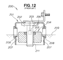
- Fig. 12 hereof is a sectional view explanatory of a fundamental construction of the conventionally-known oil level detection device 200 for an internal combustion engine, which includes: a housing 201 opening downwardly; a shaft 203 extending downward from a ceiling 202 of the housing 201; a float 204 slidably mounted on the shaft 203 and vertically movable (i.e., capable of rising and falling) in accordance with a level of oil 209 in the housing 201; a magnet 205 provided on the float 204; a reed switch 206 built in the shaft 203 to operate in response the magnet 205 approaching the switch 206; and bushes 208 attached to side surfaces 207 of the housing 201 for opening the side surfaces 207.
- the conventionally-known oil level detection device 200 for an internal combustion engine would present the inconvenience that the float 204 sticks to the ceiling 202 or bottom 211 of the housing 201, due to the viscosity of the oil, preventing the oil level from being determined accurately.
- the oil level detection device 200 is applied to a construction or civil engineering machine, such as a rammer or plate compactor, that vibrates greatly during operation, there would arise a possibility of some component parts, such as a reed switch 206, being impaired or damaged by fluctuating movement of the float 204.
- Such fluctuating movement of the float 204 would also wear the float 204, excessively fluctuate the oil level to be detected and make the float 204 stick to the housing more easily, leading to in false operation of the oil level detection device 200.
- an improved oil level detection device for an internal combustion engine which can prevent the float from sticking to the ceiling or bottom of the housing due to the viscosity of the oil and prevent excessive stress from being applied to various component parts due to vibration transmitted from a machine (such as a civil engineering machine producing great vibration) equipped with the internal combustion engine.
- an object of the present invention to provide an improved oil level detection device for an internal combustion engine which can always accurately determine an oil level by reliably preventing the float from sticking to the ceiling or bottom of the housing due to the viscosity of the oil and which, even where the device is applied to a machine that vibrates greatly, can effectively prevent damage of components parts to achieve a superior vibration resistance and thereby accurate determination of the oil level.
- the present invention provides an oil level detection device for an internal combustion engine, which comprises: a housing permitting entry therein of oil; a float provided within the housing and vertically movable with the oil entered in the housing; a switch for performing predetermined switching operation in response to the vertical movement (i.e., rising/falling) of the float within the housing; and protrusions provided, on the upper surface and/or lower surface of the float or on the ceiling and/or bottom of the housing, for preventing the float from sticking to the housing due to the viscosity of the oil.
- the oil level detection device of the present invention can reliably prevent the float from sticking to the ceiling and/or bottom of the housing due to the viscosity of the oil, with the result that the oil level can always be accurately determined and hence the reliability of the device can be significantly enhanced.
- the oil level detection device further comprises a resilient member provided, on the ceiling and/or bottom of the housing or on the upper surface and/or lower surface of the float, for lessening an impact caused when the float hits the housing.
- a resilient member provided, on the ceiling and/or bottom of the housing or on the upper surface and/or lower surface of the float, for lessening an impact caused when the float hits the housing.
- the protrusions are provided on the resilient member to project from the ceiling and/or bottom of the housing or from the upper surface and/or lower surface of the float.
- the oil level detection device of the present invention can simultaneously implement the measures to prevent the sticking and vibration of the float, as a result of which the costs of the oil level detection device can be significantly reduced.
- the internal combustion engine 10 is a single-cylinder, air-cooling engine, which comprises: a crankcase 13 having oil (lubricant oil) 12 retained therein; a crankshaft 14 extending horizontally and rotatably connected to the crankcase 13; a cylinder block 15 formed integrally with the crankcase 13; a piston 17 slidably mounted in a cylinder 16 of the cylinder block 15; a connecting rod 18 interconnecting the piston 17 and crankshaft 14; a cylinder head 21 mounted on an opening portion 19 of the cylinder block 15; an ignition plug 22 provided in an upper portion of the cylinder head 21; an air intake valve (not shown) vertically-movably mounted on the cylinder head 21; and an exhaust valve (not shown) vertically-movably mounted on the cylinder head 21.
- the crankcase 13 comprises an upper crankcase 24 having the cylinder block 15, and a lower crankcase 25 having an oil pan 26, and the upper crankcase 24 and lower crankcase 25 are attached to each other along their respective oblique surfaces.
- the crankshaft 14 is also a shaft via one end of which a driving force is output.
- the crankshaft 14 has a recoil starter 31 and cooling fan 32 mounted on its other end.
- the internal combustion engine 10 also includes bearings 33 and 34 for rotatably supporting the crankshaft 14, an engine cover 35 and a recoil starter cover 36, and the oil level detection device 40 of the present invention is employed in the engine 10; hereinafter, the oil level detection device 40 will also be referred to as "internal combustion engine employing the oil level detection device”.
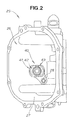
- Fig. 2 is a plan view showing the lower crankcase 25 of the internal combustion engine 10 employing the oil level detection device 40 of the present invention.
- the oil level detection device 40 is fixed, by a bolt 28, to a bottom 27 of the lower crankcase 25.
- the oil level detection device 40 is a novel oil alert device which includes arrangements for preventing sticking and vibration of a float assembly of the device 40.
- the oil level detection device 40 is suited for use in engines mounted in civil engineering machinery, such as a rammer or plate compactor, that vibrate greatly.
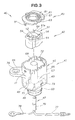
- Fig. 3 is an exploded perspective view of the internal-combustion- engine oil level detection device 40 of the present invention.
- the oil level detection device 40 comprises a housing assembly 41 mounted in the engine 10 (see Fig. 1), the float assembly 42 vertically-movably disposed within the housing assembly 41, and a cover assembly 43 covering the float assembly 42.
- the housing assembly 41 includes a resin-made housing 45, a read switch 46 disposed substantially centrally in the housing 45 (see Fig. 4), and a harness 47 extending from the read switch 46.
- the housing 45 includes a bottom 67 having a plurality of protrusions 49 partly embedded therein to partly project upward from the upper surface of the bottom 67.
- the protrusions 49 are each formed of a resilient material, and thus, they will also be referred to as a plurality of resilient members.
- the float assembly 42 includes a cylindrical float 51 having an oval shape as viewed in plan, and a magnet 52 provided integrally with a middle portion of the float 51.
- Protrusions 54 are provided, on an upper surface 51a of the float 51, for preventing the float 51 from sticking to the cover assembly 43 due to the viscosity of the oil 12.
- the cover assembly 43 includes a cover (or lid) 61 functioning as a ceiling of the housing 45, and a cover-side resilient member (e.g., anti- vibration rubber) 62 provided, on and along an inner peripheral edge of a central opening portion of the cover 61, for cushioning or lessening an impact on the float 51.
- a cover-side resilient member e.g., anti- vibration rubber
- the cover 61 has claws 81 fitted in engaging holes 72 of the housing assembly 41, and the cover-side resilient member 62 is of a ring shape and has an opening 63 through which the oil 12 is introduced.
- the housing 45 includes a body section 65 accommodating the float 51, a flange section 66 extending outwardly from the body section 65 and mounted to the bottom 27 of the engine 10 (see Fig. 1), a cylindrical section 68 extending upward from the bottom 67 of the housing 45 to surround the reed switch 46, an oil ring 69 for preventing passage of the oil between the housing 45 and the engine 10, and a lid 71 (see Fig. 4) for holding the reed switch 46 in the cylindrical section 68.
- the housing 45 further includes oil inflow ports 73, and a collar 74 embedded in the flange section 66 to enhance mounting rigidity of the flange section 66.
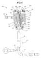
- Fig. 4 is a sectional front view of the internal-combustion-engine oil level detection device 40 of the present invention.
- the reed switch 46 is kept in an OFF state while the oil level is in a normal range, but switched to an ON state when the oil level has fallen below a predetermined threshold value.
- the reed switch 46 is accommodated in the cylindrical section 68 and fixed in place with silicon resin 76 filled in the cylindrical section 68.
- the above-mentioned harness 47 includes a positive (i.e., plus)-side wiring 77 for connection to a positive-side terminal B of a power supply (not shown), a negative (i.e., minus)-side wiring 78 for connection to an earth-side terminal of the power supply, and a tube enclosing these wirings 77 and 78.
- the oil level detection device 40 comprises the housing 45 permitting entry therein of the oil 12 (see Fig. 1), the float 51 accommodated in the housing 45 and vertically movable (i.e., capable of rising and falling) with the oil 12 entered in the housing 45, and the reed switch 46 is turned on/off in response to the vertical movement of the float 51.
- the protrusions 54 are provided, on the upper surface 51a of the float 51, for preventing the float 51 from sticking to the ceiling (cover) 61 of the housing 45 due to the viscosity of the oil 12, and the protrusions 49 are provided, on the bottom 67 of the housing 45, for preventing the float 51 from sticking to the bottom 67 of the housing 45 due to the viscosity of the oil 12.
- the oil level detection device 40 can reliably prevent the float 51 from sticking to the ceiling (cover) 61 and bottom 67 of the housing 45 due to the viscosity of the oil 12, with the result that the oil level can always be accurately determined and hence the reliability of the device 40 can be significantly enhanced.
- Figs. 5 and 6 are a plan view and bottom view, respectively, of the internal-combustion-engine oil level detection device 40 of the present invention.
- the oil level detection device 40 further includes the cover-side resilient member (e.g., anti-vibration rubber) 62 provided on the ceiling (cover) 61 for cushioning an impact imposed on the float 51 when the float 51 hits the ceiling 61, as well as the resilient members (housing-bottom- side protrusions) 49 provided on the bottom 67 for cushioning an impact imposed on the float 51 when the float 51 hits the housing 45.
- cover-side resilient member e.g., anti-vibration rubber
- Such an arrangement for cushioning an impact imposed on the float 51 when the float 51 hits the housing 45 is very advantageous because it can sufficiently protect component parts even in a case where the oil level detection device 40 is applied to a machine that vibrates greatly.
- the oil level detection device 40 of the present invention can effectively lessen an impact that would be produced due to unnecessary and excessive fluctuating movement of the float 51 in a case where the oil level detection device 40 is applied to a machine that vibrates greatly.
- the present invention can provide an improved oil level detection device 40 having a superior vibration resistance.
- the oil level detection device 40 can simultaneously implement measures to prevent the sticking and vibration of the float 51, as a result of which the costs of the oil level detection device 40 can be effectively reduced.
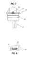
- Fig. 7 is a sectional view taken along line 7 - 7 of Fig. 6, and Fig. 8 is a sectional view taken along line 8 - 8 of Fig. 6.
- each of the resilient protrusions (i.e., bottom- side protrusions) 49 has a substantially-triangular vertical sectional shape so that a predetermined contact portion of the float 51 can contact the resilient protrusion 49 in a linear manner.
- each of the protrusions (i.e., bottom-side protrusions) 49 has a horizontal sectional shape of a substantial rail having a predetermined length.
- the predetermined length of the rail-like shape of each of the resilient protrusions 49 may be chosen as necessary. As a result, it is possible to increase design freedom of the internal-combustion-engine oil level detection device 40 of the present invention.
- Fig. 9 is a sectional front view of an oil level detection device for an internal combustion engine in accordance with a second embodiment of the present invention.
- the oil level detection device 90 according to the second embodiment comprises: a housing assembly 91 mounted in the engine and including a housing 95 permitting entry therein of oil; a float assembly 92 having a float 101 vertically movable with the oil in the housing 95; a cover assembly 93 covering the float assembly 92; a reed switch 96 that is turned on/off in response to the vertical movement of the float 101 and has a harness 97; a flat-plate-shaped resilient member 98 provided on a bottom 117 of the housing 95; a magnet 102 provided integrally with the float 101; a plurality of protrusions (upper-float-surface protrusions) 104 provided on an upper surface 101a of the float 101; a plurality of protrusions (lower-float-surface protrusions) 106 provided on a lower surface 101b of the float
- the oil level detection device 90 is characterized by implementing the measures to prevent the sticking and vibration of the float 101, by means of the flat-plate-shaped resilient member 98 provided on the bottom 117 of the housing 95, the cover-side resilient member (anti-vibration rubber) 112 provided on the cover or ceiling 111 of the housing 95, the plurality of protrusions 104 provided on the upper surface 101a of the float 101 and the plurality of protrusions 106 provided on the lower surface 101b of the float 101.
- Fig. 10 is a sectional front view of an oil level detection device for an internal combustion engine in accordance with a third embodiment of the present invention.
- the oil level detection device 120 according to the third embodiment comprises: a housing assembly 121 mounted in the engine and including a housing 125 permitting entry therein of oil; a float assembly 122 having a float 131 vertically movable with the oil in the housing 125; a cover assembly 123 covering the float assembly 122; a reed switch 126 that is turned on/off in response to the vertical movement of the float 131 and has a harness 127; a plurality of housing-bottom-side protrusions 129 provided on a bottom 147 of the housing 125 (these protrusions 129 are similar to the bottom-side protrusions 49 shown in Fig.
- a magnet 132 provided integrally with the float 131; cover or ceiling 141 of the housing 125; a cover-side resilient member (anti-vibration rubber) 142 provided on the cover or ceiling 141 of the housing 125; and a plurality of cover-side protrusions 143 provided on the lower surface of the cover-side resilient member 142.
- the oil level detection device 120 is characterized by implementing the measures to prevent the sticking and vibration of the float 131, by means of the bottom-side protrusions 129 provided on the bottom 147 of the housing 125, the resilient member 142 provided on the cover or ceiling 141 of the housing 125 and the cover-side protrusions 143 provided on the lower surface of the resilient member 142.
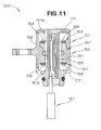
- Fig. 11 is a sectional front view of an oil level detection device for an internal combustion engine in accordance with a fourth embodiment of the present invention.
- the oil level detection device 150 according to the fourth embodiment comprises: a housing assembly 151 mounted in the engine and including a housing 155 permitting entry therein of oil; a float assembly 152 having a float 161 vertically movable with the oil in the housing 155; a reed switch 156 that is turned on/off in response to the vertical movement of the float 161 and has a harness 157; an upper resilient member 163 provided on an upper surface 161a of the float 161; a magnet 162 provided integrally with the float 161; a plurality of upper-side protrusions 164 provided on the upper surface of the upper resilient member 163; a lower resilient member 165 provided on a lower surface 161b of the float 161; and a plurality of lower-side protrusions 166 provided on the lower surface of the lower resilient member 165.
- the oil level detection device 150 is characterized by implementing the measures to prevent the sticking and vibration of the float 161, by means of the upper resilient member 163 provided on the upper surface 161a of the float 161, the plurality of upper-side protrusions 164 provided on the upper surface of the upper resilient member 163, the lower resilient member 165 provided on the lower surface 161b of the float 161 and the plurality of lower-side protrusions 166 provided on the lower surface of the lower resilient member 165.
- the aforementioned protrusions may be provided on the upper surface and/or lower surface of the float, or on the ceiling and/or bottom of the housing.
- the aforementioned resilient member may be provided on the ceiling and/or bottom of the housing, or on the upper surface and/or lower surface of the float.
- the protrusions may be provided on the resilient members to project from the ceiling and/or bottom of the housing, or from the upper surface and/or lower surface of the float.
- the present invention may use any desired combination of such protrusions and resilient members.
- the oil level detection device of the present invention arranged in the above-described manner is very suitable for use in engines mounted on civil engineering or construction machines, such as rammers and plate compactors, that greatly vibrate during operation.
- An oil level detection device 40; 90; 120; 150 for an internal combustion engine 10 which comprises: a housing 45; 95; 125; 155 permitting entry therein of oil 12; a float 51; 101; 131; 161 provided within the housing and vertically movable with the oil entered in the housing; a switch 46; 96; 126; 156 for performing switching operation in response to the vertical movement of the float within the housing; protrusions 54; 104 provided, on the upper surface 51a of the float, for preventing the float from sticking to the ceiling 61 of the housing due to viscosity of the oil; and protrusions 49; 129 provided, on the bottom 67; 147 of the housing, for preventing the float from sticking to the bottom of the housing due to viscosity of the oil.
Landscapes
- Engineering & Computer Science (AREA)
- Physics & Mathematics (AREA)
- Fluid Mechanics (AREA)
- General Physics & Mathematics (AREA)
- Mechanical Engineering (AREA)
- General Engineering & Computer Science (AREA)
- Lubrication Details And Ventilation Of Internal Combustion Engines (AREA)
- Level Indicators Using A Float (AREA)
Abstract
Description
- The present invention relates to an improved oil level detection device capable of accurately detecting an excessive fall of an oil level in an internal combustion engine.
- Among the oil level detection devices for internal combustion engines in practical use today are ones where a float is provided within a housing, oil is introduced into the housing, and an excessive fall of an oil level is indicated to a user or the like when the float has lowered to a predetermined position.
- For practical purposes, the conventional oil level detection devices for internal combustion engines have been considered satisfactory if they are constructed to allow the float to be unsusceptible to transitory oil level fluctuations. Examples of such oil level detection devices for internal combustion engines include one that employs a combination of a float and reed switch, as known, for example, from
Japanese Utility Model Laid-Open Publication No. SHO-56-56143 JP-UM-56-056143A - Fig. 12 hereof is a sectional view explanatory of a fundamental construction of the conventionally-known oil
level detection device 200 for an internal combustion engine, which includes: ahousing 201 opening downwardly; ashaft 203 extending downward from aceiling 202 of thehousing 201; afloat 204 slidably mounted on theshaft 203 and vertically movable (i.e., capable of rising and falling) in accordance with a level ofoil 209 in thehousing 201; amagnet 205 provided on thefloat 204; areed switch 206 built in theshaft 203 to operate in response themagnet 205 approaching theswitch 206; andbushes 208 attached toside surfaces 207 of thehousing 201 for opening theside surfaces 207. - However, the conventionally-known oil
level detection device 200 for an internal combustion engine would present the inconvenience that thefloat 204 sticks to theceiling 202 orbottom 211 of thehousing 201, due to the viscosity of the oil, preventing the oil level from being determined accurately. Further, in cases where the oillevel detection device 200 is applied to a construction or civil engineering machine, such as a rammer or plate compactor, that vibrates greatly during operation, there would arise a possibility of some component parts, such as areed switch 206, being impaired or damaged by fluctuating movement of thefloat 204. Such fluctuating movement of thefloat 204 would also wear thefloat 204, excessively fluctuate the oil level to be detected and make thefloat 204 stick to the housing more easily, leading to in false operation of the oillevel detection device 200. - Thus, there has been a great demand for an improved oil level detection device for an internal combustion engine which can prevent the float from sticking to the ceiling or bottom of the housing due to the viscosity of the oil and prevent excessive stress from being applied to various component parts due to vibration transmitted from a machine (such as a civil engineering machine producing great vibration) equipped with the internal combustion engine.
- In view of the foregoing prior art problems, it is an object of the present invention to provide an improved oil level detection device for an internal combustion engine which can always accurately determine an oil level by reliably preventing the float from sticking to the ceiling or bottom of the housing due to the viscosity of the oil and which, even where the device is applied to a machine that vibrates greatly, can effectively prevent damage of components parts to achieve a superior vibration resistance and thereby accurate determination of the oil level.
- In order to accomplish the above-mentioned object, the present invention provides an oil level detection device for an internal combustion engine, which comprises: a housing permitting entry therein of oil; a float provided within the housing and vertically movable with the oil entered in the housing; a switch for performing predetermined switching operation in response to the vertical movement (i.e., rising/falling) of the float within the housing; and protrusions provided, on the upper surface and/or lower surface of the float or on the ceiling and/or bottom of the housing, for preventing the float from sticking to the housing due to the viscosity of the oil.
- By the provision of the protrusions on the upper surface and/or lower surface of the float or on the ceiling and/or bottom of the housing, the oil level detection device of the present invention can reliably prevent the float from sticking to the ceiling and/or bottom of the housing due to the viscosity of the oil, with the result that the oil level can always be accurately determined and hence the reliability of the device can be significantly enhanced.
- In a preferred embodiment, the oil level detection device further comprises a resilient member provided, on the ceiling and/or bottom of the housing or on the upper surface and/or lower surface of the float, for lessening an impact caused when the float hits the housing. Thus, the oil level detection device of the present invention can simultaneously implement measures to prevent the sticking and vibration of the float, as a result of which the costs of the oil level detection device can be significantly reduced.
- In a preferred embodiment, the protrusions are provided on the resilient member to project from the ceiling and/or bottom of the housing or from the upper surface and/or lower surface of the float. Thus, in this case too, the oil level detection device of the present invention can simultaneously implement the measures to prevent the sticking and vibration of the float, as a result of which the costs of the oil level detection device can be significantly reduced.
- Certain preferred embodiments of the present invention will hereinafter be described in detail, by way of example only, with reference to the accompanying drawings, in which:
- Fig. 1 is a sectional side view of an internal combustion engine employing an oil level detection device in accordance with a first embodiment of the present invention;
- Fig. 2 is a plan view showing a lower crankcase of the internal combustion engine employing the oil level detection device of the present invention;
- Fig. 3 is an exploded perspective view of the internal-combustion- engine oil level detection device of the present invention;
- Fig. 4 is a sectional front view of the internal-combustion-engine oil level detection device of the present invention;
- Fig. 5 is a plan view of the internal-combustion-engine oil level detection device of the present invention;
- Fig. 6 is a bottom view of the internal-combustion-engine oil level detection device of the present invention;
- Fig. 7 is a sectional view taken along line 7 - 7 of Fig. 6;
- Fig. 8 is a sectional view taken along line 8 - 8 of Fig. 6;
- Fig. 9 is a sectional front view of an oil level detection device for an internal combustion engine in accordance with a second embodiment of the present invention;
- Fig. 10 is a sectional front view of an oil level detection device for an internal combustion engine in accordance with a third embodiment of the present invention;
- Fig. 11 is a sectional front view of an oil level detection device for an internal combustion engine in accordance with a fourth embodiment of the present invention; and
- Fig. 12 is a view explanatory of a fundamental construction of a conventionally-known oil level detection device for an internal combustion engine.
- Initial reference is made to Fig. 1 showing in sectional side elevation an
internal combustion engine 10 employing an oil level detection device in accordance with a first embodiment of the present invention. The internal combustion engine (general-purpose engine) 10 is a single-cylinder, air-cooling engine, which comprises: acrankcase 13 having oil (lubricant oil) 12 retained therein; acrankshaft 14 extending horizontally and rotatably connected to thecrankcase 13; acylinder block 15 formed integrally with thecrankcase 13; apiston 17 slidably mounted in acylinder 16 of thecylinder block 15; a connectingrod 18 interconnecting thepiston 17 andcrankshaft 14; acylinder head 21 mounted on anopening portion 19 of thecylinder block 15; anignition plug 22 provided in an upper portion of thecylinder head 21; an air intake valve (not shown) vertically-movably mounted on thecylinder head 21; and an exhaust valve (not shown) vertically-movably mounted on thecylinder head 21. - The
crankcase 13 comprises anupper crankcase 24 having thecylinder block 15, and alower crankcase 25 having anoil pan 26, and theupper crankcase 24 andlower crankcase 25 are attached to each other along their respective oblique surfaces. Thecrankshaft 14 is also a shaft via one end of which a driving force is output. Thecrankshaft 14 has arecoil starter 31 andcooling fan 32 mounted on its other end. - The
internal combustion engine 10 also includesbearings crankshaft 14, anengine cover 35 and arecoil starter cover 36, and the oillevel detection device 40 of the present invention is employed in theengine 10; hereinafter, the oillevel detection device 40 will also be referred to as "internal combustion engine employing the oil level detection device". - Fig. 2 is a plan view showing the
lower crankcase 25 of theinternal combustion engine 10 employing the oillevel detection device 40 of the present invention. - The oil
level detection device 40 is fixed, by abolt 28, to abottom 27 of thelower crankcase 25. As will be later detailed, the oillevel detection device 40 is a novel oil alert device which includes arrangements for preventing sticking and vibration of a float assembly of thedevice 40. Thus, the oillevel detection device 40 is suited for use in engines mounted in civil engineering machinery, such as a rammer or plate compactor, that vibrate greatly. - Fig. 3 is an exploded perspective view of the internal-combustion- engine oil
level detection device 40 of the present invention. The oillevel detection device 40 comprises ahousing assembly 41 mounted in the engine 10 (see Fig. 1), thefloat assembly 42 vertically-movably disposed within thehousing assembly 41, and acover assembly 43 covering thefloat assembly 42. - The
housing assembly 41 includes a resin-madehousing 45, aread switch 46 disposed substantially centrally in the housing 45 (see Fig. 4), and aharness 47 extending from theread switch 46. Thehousing 45 includes abottom 67 having a plurality ofprotrusions 49 partly embedded therein to partly project upward from the upper surface of thebottom 67. Theprotrusions 49 are each formed of a resilient material, and thus, they will also be referred to as a plurality of resilient members. - The
float assembly 42 includes acylindrical float 51 having an oval shape as viewed in plan, and amagnet 52 provided integrally with a middle portion of thefloat 51.Protrusions 54 are provided, on anupper surface 51a of thefloat 51, for preventing thefloat 51 from sticking to thecover assembly 43 due to the viscosity of theoil 12. - The
cover assembly 43 includes a cover (or lid) 61 functioning as a ceiling of thehousing 45, and a cover-side resilient member (e.g., anti- vibration rubber) 62 provided, on and along an inner peripheral edge of a central opening portion of thecover 61, for cushioning or lessening an impact on thefloat 51. - The
cover 61 hasclaws 81 fitted inengaging holes 72 of thehousing assembly 41, and the cover-sideresilient member 62 is of a ring shape and has anopening 63 through which theoil 12 is introduced. - The
housing 45 includes abody section 65 accommodating thefloat 51, aflange section 66 extending outwardly from thebody section 65 and mounted to thebottom 27 of the engine 10 (see Fig. 1), acylindrical section 68 extending upward from thebottom 67 of thehousing 45 to surround thereed switch 46, anoil ring 69 for preventing passage of the oil between thehousing 45 and theengine 10, and a lid 71 (see Fig. 4) for holding thereed switch 46 in thecylindrical section 68. Thehousing 45 further includesoil inflow ports 73, and acollar 74 embedded in theflange section 66 to enhance mounting rigidity of theflange section 66. - Fig. 4 is a sectional front view of the internal-combustion-engine oil
level detection device 40 of the present invention. - The
reed switch 46 is kept in an OFF state while the oil level is in a normal range, but switched to an ON state when the oil level has fallen below a predetermined threshold value. Thereed switch 46 is accommodated in thecylindrical section 68 and fixed in place withsilicon resin 76 filled in thecylindrical section 68. - The above-mentioned
harness 47 includes a positive (i.e., plus)-side wiring 77 for connection to a positive-side terminal B of a power supply (not shown), a negative (i.e., minus)-side wiring 78 for connection to an earth-side terminal of the power supply, and a tube enclosing thesewirings - Briefly speaking, the oil
level detection device 40 comprises thehousing 45 permitting entry therein of the oil 12 (see Fig. 1), thefloat 51 accommodated in thehousing 45 and vertically movable (i.e., capable of rising and falling) with theoil 12 entered in thehousing 45, and thereed switch 46 is turned on/off in response to the vertical movement of thefloat 51. Theprotrusions 54 are provided, on theupper surface 51a of thefloat 51, for preventing thefloat 51 from sticking to the ceiling (cover) 61 of thehousing 45 due to the viscosity of theoil 12, and theprotrusions 49 are provided, on thebottom 67 of thehousing 45, for preventing thefloat 51 from sticking to thebottom 67 of thehousing 45 due to the viscosity of theoil 12. - Preventing the
float 51 from sticking to theceiling 61 andbottom 67 due to the viscosity of theoil 12 is preferable in that, by so doing, the oil level can always be accurately detected or determined. By the provision of the protrusions (i.e., upper-float-surface protrusion) 54 and protrusions (i.e., housing-bottom-side protrusions) 49, the oillevel detection device 40 can reliably prevent thefloat 51 from sticking to the ceiling (cover) 61 andbottom 67 of thehousing 45 due to the viscosity of theoil 12, with the result that the oil level can always be accurately determined and hence the reliability of thedevice 40 can be significantly enhanced. - Figs. 5 and 6 are a plan view and bottom view, respectively, of the internal-combustion-engine oil
level detection device 40 of the present invention. - As shown, the oil
level detection device 40 further includes the cover-side resilient member (e.g., anti-vibration rubber) 62 provided on the ceiling (cover) 61 for cushioning an impact imposed on thefloat 51 when thefloat 51 hits theceiling 61, as well as the resilient members (housing-bottom- side protrusions) 49 provided on thebottom 67 for cushioning an impact imposed on thefloat 51 when thefloat 51 hits thehousing 45. - Such an arrangement for cushioning an impact imposed on the
float 51 when thefloat 51 hits thehousing 45 is very advantageous because it can sufficiently protect component parts even in a case where the oillevel detection device 40 is applied to a machine that vibrates greatly. - With the
resilient member 62 provided on thecover 61 for cushioning an impact on thefloat 51 when thefloat 15 hits theceiling 61 and with the resilient members (housing-bottom-side protrusions) 49 provided on thebottom 67 for cushioning an impact imposed on thefloat 51 when thefloat 51 hits thehousing 45, the oillevel detection device 40 of the present invention can effectively lessen an impact that would be produced due to unnecessary and excessive fluctuating movement of thefloat 51 in a case where the oillevel detection device 40 is applied to a machine that vibrates greatly. Thus, the present invention can provide an improved oillevel detection device 40 having a superior vibration resistance. - Further, with the
resilient member 62 and theresilient protrusions 49 provided on and projecting from thebottom 67, the oillevel detection device 40 can simultaneously implement measures to prevent the sticking and vibration of thefloat 51, as a result of which the costs of the oillevel detection device 40 can be effectively reduced. - Fig. 7 is a sectional view taken along line 7 - 7 of Fig. 6, and Fig. 8 is a sectional view taken along line 8 - 8 of Fig. 6.
- As shown in Fig. 7, each of the resilient protrusions (i.e., bottom- side protrusions) 49 has a substantially-triangular vertical sectional shape so that a predetermined contact portion of the
float 51 can contact theresilient protrusion 49 in a linear manner. As shown in Fig. 8, each of the protrusions (i.e., bottom-side protrusions) 49 has a horizontal sectional shape of a substantial rail having a predetermined length. - To implement the measures for preventing the sticking and vibration of the
float 51, the predetermined length of the rail-like shape of each of theresilient protrusions 49 may be chosen as necessary. As a result, it is possible to increase design freedom of the internal-combustion-engine oillevel detection device 40 of the present invention. - Fig. 9 is a sectional front view of an oil level detection device for an internal combustion engine in accordance with a second embodiment of the present invention. The oil
level detection device 90 according to the second embodiment comprises: ahousing assembly 91 mounted in the engine and including ahousing 95 permitting entry therein of oil; afloat assembly 92 having afloat 101 vertically movable with the oil in thehousing 95; acover assembly 93 covering thefloat assembly 92; areed switch 96 that is turned on/off in response to the vertical movement of thefloat 101 and has aharness 97; a flat-plate-shapedresilient member 98 provided on abottom 117 of thehousing 95; amagnet 102 provided integrally with thefloat 101; a plurality of protrusions (upper-float-surface protrusions) 104 provided on anupper surface 101a of thefloat 101; a plurality of protrusions (lower-float-surface protrusions) 106 provided on alower surface 101b of thefloat 101; and a cover-side resilient member (e.g., anti-vibration rubber) 112 provided on a cover or ceiling 111 of thehousing 95. - Namely, the oil
level detection device 90 according to the second embodiment is characterized by implementing the measures to prevent the sticking and vibration of thefloat 101, by means of the flat-plate-shapedresilient member 98 provided on thebottom 117 of thehousing 95, the cover-side resilient member (anti-vibration rubber) 112 provided on the cover or ceiling 111 of thehousing 95, the plurality ofprotrusions 104 provided on theupper surface 101a of thefloat 101 and the plurality ofprotrusions 106 provided on thelower surface 101b of thefloat 101. - Further, Fig. 10 is a sectional front view of an oil level detection device for an internal combustion engine in accordance with a third embodiment of the present invention. The oil
level detection device 120 according to the third embodiment comprises: ahousing assembly 121 mounted in the engine and including ahousing 125 permitting entry therein of oil; afloat assembly 122 having afloat 131 vertically movable with the oil in thehousing 125; acover assembly 123 covering thefloat assembly 122; areed switch 126 that is turned on/off in response to the vertical movement of thefloat 131 and has aharness 127; a plurality of housing-bottom-side protrusions 129 provided on abottom 147 of the housing 125 (theseprotrusions 129 are similar to the bottom-side protrusions 49 shown in Fig. 8); amagnet 132 provided integrally with thefloat 131; cover orceiling 141 of thehousing 125; a cover-side resilient member (anti-vibration rubber) 142 provided on the cover orceiling 141 of thehousing 125; and a plurality of cover-side protrusions 143 provided on the lower surface of the cover-sideresilient member 142. - Namely, the oil
level detection device 120 according to the third embodiment is characterized by implementing the measures to prevent the sticking and vibration of thefloat 131, by means of the bottom-side protrusions 129 provided on thebottom 147 of thehousing 125, theresilient member 142 provided on the cover orceiling 141 of thehousing 125 and the cover-side protrusions 143 provided on the lower surface of theresilient member 142. - Fig. 11 is a sectional front view of an oil level detection device for an internal combustion engine in accordance with a fourth embodiment of the present invention. The oil
level detection device 150 according to the fourth embodiment comprises: ahousing assembly 151 mounted in the engine and including ahousing 155 permitting entry therein of oil; afloat assembly 152 having afloat 161 vertically movable with the oil in thehousing 155; areed switch 156 that is turned on/off in response to the vertical movement of thefloat 161 and has aharness 157; an upperresilient member 163 provided on anupper surface 161a of thefloat 161; amagnet 162 provided integrally with thefloat 161; a plurality of upper-side protrusions 164 provided on the upper surface of the upperresilient member 163; a lowerresilient member 165 provided on alower surface 161b of thefloat 161; and a plurality of lower-side protrusions 166 provided on the lower surface of the lowerresilient member 165.Reference numeral 171 indicates a cover or ceiling of thehousing 155, and 177 a bottom of thehousing 155. - Namely, the oil
level detection device 150 according to the fourth embodiment is characterized by implementing the measures to prevent the sticking and vibration of thefloat 161, by means of the upperresilient member 163 provided on theupper surface 161a of thefloat 161, the plurality of upper-side protrusions 164 provided on the upper surface of the upperresilient member 163, the lowerresilient member 165 provided on thelower surface 161b of thefloat 161 and the plurality of lower-side protrusions 166 provided on the lower surface of the lowerresilient member 165. - In the oil level detection device of the present invention, as seen in Figs. 4, 9, 10 and 11, the aforementioned protrusions may be provided on the upper surface and/or lower surface of the float, or on the ceiling and/or bottom of the housing. Further, the aforementioned resilient member may be provided on the ceiling and/or bottom of the housing, or on the upper surface and/or lower surface of the float. Further, the protrusions may be provided on the resilient members to project from the ceiling and/or bottom of the housing, or from the upper surface and/or lower surface of the float. Further, the present invention may use any desired combination of such protrusions and resilient members.
- The oil level detection device of the present invention arranged in the above-described manner is very suitable for use in engines mounted on civil engineering or construction machines, such as rammers and plate compactors, that greatly vibrate during operation.
- An oil
level detection device 40; 90; 120; 150 for aninternal combustion engine 10; which comprises: ahousing 45; 95; 125; 155 permitting entry therein ofoil 12; afloat 51; 101; 131; 161 provided within the housing and vertically movable with the oil entered in the housing; aswitch 46; 96; 126; 156 for performing switching operation in response to the vertical movement of the float within the housing;protrusions 54; 104 provided, on theupper surface 51a of the float, for preventing the float from sticking to theceiling 61 of the housing due to viscosity of the oil; andprotrusions 49; 129 provided, on the bottom 67; 147 of the housing, for preventing the float from sticking to the bottom of the housing due to viscosity of the oil.
Claims (3)
- An oil level detection device (40; 90; 120; 150) for an internal combustion engine (10), comprising:a housing (45; 95; 125; 155) permitting entry therein of oil (12);a float (51; 101; 131; 161) provided within said housing and vertically movable with the oil entered in said housing;a switch (46; 96; 126; 156) for performing switching operation in response to vertical movement of said float within said housing; andprotrusions (49, 54; 104, 106; 129) provided, on an upper surface (51a; 101a) and/or lower surface (101b) of said float or on a ceiling and/or bottom (67; 147) of said housing, for preventing said float from sticking to said housing due to viscosity of the oil.
- The oil level detection device of claim 1, which further comprises a resilient member (62; 98, 112; 142; 163, 165) provided, on the ceiling (61; 111; 141) and/or bottom (117) of said housing or on the upper surface and/or lower surface of said float, for lessening an impact caused when said float hits said housing.
- The oil level detection device of claim 2, wherein said protrusions (143; 164, 166) are provided on said resilient member (142; 163, 165) to project from the ceiling (141) and/or bottom of said housing or from the upper surface (161a) and/or lower surface (161b) of said float.
Applications Claiming Priority (1)
| Application Number | Priority Date | Filing Date | Title |
|---|---|---|---|
| JP2006033665A JP4699911B2 (en) | 2006-02-10 | 2006-02-10 | Oil level detection device for internal combustion engine for civil engineering machinery |
Publications (3)
| Publication Number | Publication Date |
|---|---|
| EP1818656A2 true EP1818656A2 (en) | 2007-08-15 |
| EP1818656A3 EP1818656A3 (en) | 2009-03-04 |
| EP1818656B1 EP1818656B1 (en) | 2013-12-04 |
Family
ID=37890620
Family Applications (1)
| Application Number | Title | Priority Date | Filing Date |
|---|---|---|---|
| EP07000362.9A Expired - Fee Related EP1818656B1 (en) | 2006-02-10 | 2007-01-09 | Oil level detection device for internal combustion engine |
Country Status (5)
| Country | Link |
|---|---|
| US (1) | US7688193B2 (en) |
| EP (1) | EP1818656B1 (en) |
| JP (1) | JP4699911B2 (en) |
| CN (2) | CN101017746B (en) |
| ES (1) | ES2439737T3 (en) |
Cited By (2)
| Publication number | Priority date | Publication date | Assignee | Title |
|---|---|---|---|---|
| CN102400739A (en) * | 2011-09-15 | 2012-04-04 | 沈阳黎明航空发动机(集团)有限责任公司 | Device for dynamically measuring liquid level of lubricating oil tank of aircraft engine in real time |
| CN103511319A (en) * | 2012-06-18 | 2014-01-15 | 上海连成(集团)有限公司 | Oil level measuring structure of vertical type axial flow pump |
Families Citing this family (4)
| Publication number | Priority date | Publication date | Assignee | Title |
|---|---|---|---|---|
| JP4699911B2 (en) * | 2006-02-10 | 2011-06-15 | 本田技研工業株式会社 | Oil level detection device for internal combustion engine for civil engineering machinery |
| JP5510396B2 (en) * | 2011-06-16 | 2014-06-04 | 株式会社デンソー | Liquid level sensor |
| US20140183021A1 (en) * | 2012-12-28 | 2014-07-03 | Yung-Chih Tsai | Float switch device with magnetic tongue |
| US9175585B2 (en) * | 2013-05-24 | 2015-11-03 | GM Global Technology Operations LLC | Fluid level detection device with stabilizer |
Citations (2)
| Publication number | Priority date | Publication date | Assignee | Title |
|---|---|---|---|---|
| US3258968A (en) | 1963-10-02 | 1966-07-05 | Stewart Warner Corp | Liquid level indicating device |
| US5216421A (en) | 1989-09-25 | 1993-06-01 | Moriyama Kogyo Kabushiki Kaisha | Indicator for small watercraft |
Family Cites Families (17)
| Publication number | Priority date | Publication date | Assignee | Title |
|---|---|---|---|---|
| US3200645A (en) * | 1963-05-22 | 1965-08-17 | Gen Electric | Electric position sensor |
| US3949360A (en) * | 1974-07-23 | 1976-04-06 | Richard Pignata | Oil level detector and indicator |
| JPS5919295Y2 (en) * | 1979-10-06 | 1984-06-04 | 富士重工業株式会社 | float switch |
| JPS6047814A (en) * | 1983-08-26 | 1985-03-15 | Honda Motor Co Ltd | Oil-level detecting apparatus for engine |
| DE3445541A1 (en) * | 1984-01-04 | 1985-07-11 | Skandiafabriken AB, Mullsjö | LIQUID LEVEL INDICATOR |
| JPH059798Y2 (en) * | 1986-01-13 | 1993-03-10 | ||
| JP3023118B2 (en) * | 1989-09-25 | 2000-03-21 | 森山工業株式会社 | Liquid level detector for small boats |
| JPH08201144A (en) * | 1995-01-31 | 1996-08-09 | Hitachi Ltd | Liquid level detector |
| KR200170993Y1 (en) * | 1996-10-07 | 2000-04-01 | 정몽규 | Oil pan checking system |
| JP2001271952A (en) * | 2000-03-24 | 2001-10-05 | Shin Meiwa Ind Co Ltd | Exhaust valve |
| JP2003232494A (en) * | 2002-02-08 | 2003-08-22 | Aisan Ind Co Ltd | Trap |
| US7398682B2 (en) * | 2003-11-18 | 2008-07-15 | Innercool Therapies, Inc. | Low fluid level detector system |
| JP2006137501A (en) | 2004-11-10 | 2006-06-01 | Seiko Epson Corp | Origin position detection device, recording device, and controlling method for them |
| JP4222322B2 (en) * | 2005-02-01 | 2009-02-12 | 株式会社デンソー | Liquid level detector |
| JP4391968B2 (en) * | 2005-06-23 | 2009-12-24 | 本田技研工業株式会社 | Oil level detection device for internal combustion engine |
| MY140672A (en) * | 2005-06-23 | 2010-01-15 | Honda Motor Co Ltd | Engine oil level detection system |
| JP4699911B2 (en) * | 2006-02-10 | 2011-06-15 | 本田技研工業株式会社 | Oil level detection device for internal combustion engine for civil engineering machinery |
-
2006
- 2006-02-10 JP JP2006033665A patent/JP4699911B2/en not_active Expired - Fee Related
-
2007
- 2007-01-09 EP EP07000362.9A patent/EP1818656B1/en not_active Expired - Fee Related
- 2007-01-09 ES ES07000362.9T patent/ES2439737T3/en active Active
- 2007-01-26 US US11/698,037 patent/US7688193B2/en active Active
- 2007-02-08 CN CN2007100070911A patent/CN101017746B/en active Active
- 2007-02-08 CN CNU2007200021889U patent/CN200990341Y/en not_active Expired - Lifetime
Patent Citations (2)
| Publication number | Priority date | Publication date | Assignee | Title |
|---|---|---|---|---|
| US3258968A (en) | 1963-10-02 | 1966-07-05 | Stewart Warner Corp | Liquid level indicating device |
| US5216421A (en) | 1989-09-25 | 1993-06-01 | Moriyama Kogyo Kabushiki Kaisha | Indicator for small watercraft |
Cited By (2)
| Publication number | Priority date | Publication date | Assignee | Title |
|---|---|---|---|---|
| CN102400739A (en) * | 2011-09-15 | 2012-04-04 | 沈阳黎明航空发动机(集团)有限责任公司 | Device for dynamically measuring liquid level of lubricating oil tank of aircraft engine in real time |
| CN103511319A (en) * | 2012-06-18 | 2014-01-15 | 上海连成(集团)有限公司 | Oil level measuring structure of vertical type axial flow pump |
Also Published As
| Publication number | Publication date |
|---|---|
| EP1818656A3 (en) | 2009-03-04 |
| JP4699911B2 (en) | 2011-06-15 |
| CN101017746B (en) | 2010-05-19 |
| JP2007211711A (en) | 2007-08-23 |
| EP1818656B1 (en) | 2013-12-04 |
| US7688193B2 (en) | 2010-03-30 |
| ES2439737T3 (en) | 2014-01-24 |
| CN101017746A (en) | 2007-08-15 |
| CN200990341Y (en) | 2007-12-12 |
| US20070194941A1 (en) | 2007-08-23 |
Similar Documents
| Publication | Publication Date | Title |
|---|---|---|
| EP1818656B1 (en) | Oil level detection device for internal combustion engine | |
| EP1840921B1 (en) | Fluid level switch | |
| KR100941362B1 (en) | Engine oil level detection system and engine oil level detection method | |
| CA2651955A1 (en) | Oil sensor placement structure in engine | |
| SE455214B (en) | PROCEDURE FOR MONITORING THE OIL VOLUME IN THE WEB HOUSE BY A PISTON ENGINE AND ENGINE FOR IMPLEMENTATION OF THE PROCEDURE | |
| US4622935A (en) | Low level lubricating oil detector | |
| EP1762847A3 (en) | Oil pan for automotive engines | |
| EP1522707A3 (en) | Cylinder block for internal combustion engine | |
| JP4886380B2 (en) | Engine oil level detection device and oil level detection method | |
| US6227921B1 (en) | Marine propulsion device with an oil gage accessible through a cowl | |
| JP4391968B2 (en) | Oil level detection device for internal combustion engine | |
| EP1174895B1 (en) | Fluid level sensing switch | |
| EP1482135A3 (en) | Oil pan structure for an engine | |
| CN209483453U (en) | Oil pan structure, engine and vehicle | |
| CN207231601U (en) | A kind of food tray oil mass detection device of sewing machine | |
| JP2631405B2 (en) | Equipment for engine cooling water and lubricating oil | |
| JPH0536976Y2 (en) | ||
| US20130030677A1 (en) | Drive system with an apparatus for interrupting the operation in the case of an imminent lack of operating medium | |
| JPS6075709A (en) | Seizure preventive device of spark ignition engine | |
| FR2870597B1 (en) | VIBRATION SIMULATION DEVICE, AND INTERNAL COMBUSTION ENGINE TEST BENCH EQUIPPED WITH SUCH A DEVICE | |
| TH59007B (en) | Balance device for engine | |
| JP2005220869A (en) | Oil sensor of multipurpose engine | |
| JPS5921354Y2 (en) | Anti-vibration support device for engine frame | |
| TH85010A (en) | engine | |
| TH37841B (en) | engine |
Legal Events
| Date | Code | Title | Description |
|---|---|---|---|
| PUAI | Public reference made under article 153(3) epc to a published international application that has entered the european phase |
Free format text: ORIGINAL CODE: 0009012 |
|
| 17P | Request for examination filed |
Effective date: 20070109 |
|
| AK | Designated contracting states |
Kind code of ref document: A2 Designated state(s): AT BE BG CH CY CZ DE DK EE ES FI FR GB GR HU IE IS IT LI LT LU LV MC NL PL PT RO SE SI SK TR |
|
| AX | Request for extension of the european patent |
Extension state: AL BA HR MK YU |
|
| PUAL | Search report despatched |
Free format text: ORIGINAL CODE: 0009013 |
|
| AK | Designated contracting states |
Kind code of ref document: A3 Designated state(s): AT BE BG CH CY CZ DE DK EE ES FI FR GB GR HU IE IS IT LI LT LU LV MC NL PL PT RO SE SI SK TR |
|
| AX | Request for extension of the european patent |
Extension state: AL BA HR MK RS |
|
| RIC1 | Information provided on ipc code assigned before grant |
Ipc: F01M 11/12 20060101ALI20090128BHEP Ipc: G01F 23/64 20060101ALI20090128BHEP Ipc: G01F 23/30 20060101ALI20090128BHEP Ipc: G01F 23/74 20060101AFI20070403BHEP |
|
| 17Q | First examination report despatched |
Effective date: 20090811 |
|
| AKX | Designation fees paid |
Designated state(s): DE ES FR GB IT |
|
| GRAP | Despatch of communication of intention to grant a patent |
Free format text: ORIGINAL CODE: EPIDOSNIGR1 |
|
| INTG | Intention to grant announced |
Effective date: 20130627 |
|
| GRAS | Grant fee paid |
Free format text: ORIGINAL CODE: EPIDOSNIGR3 |
|
| GRAA | (expected) grant |
Free format text: ORIGINAL CODE: 0009210 |
|
| AK | Designated contracting states |
Kind code of ref document: B1 Designated state(s): DE ES FR GB IT |
|
| REG | Reference to a national code |
Ref country code: GB Ref legal event code: FG4D |
|
| REG | Reference to a national code |
Ref country code: ES Ref legal event code: FG2A Ref document number: 2439737 Country of ref document: ES Kind code of ref document: T3 Effective date: 20140124 |
|
| REG | Reference to a national code |
Ref country code: DE Ref legal event code: R096 Ref document number: 602007034069 Country of ref document: DE Effective date: 20140130 |
|
| REG | Reference to a national code |
Ref country code: DE Ref legal event code: R097 Ref document number: 602007034069 Country of ref document: DE |
|
| PLBE | No opposition filed within time limit |
Free format text: ORIGINAL CODE: 0009261 |
|
| STAA | Information on the status of an ep patent application or granted ep patent |
Free format text: STATUS: NO OPPOSITION FILED WITHIN TIME LIMIT |
|
| 26N | No opposition filed |
Effective date: 20140905 |
|
| REG | Reference to a national code |
Ref country code: DE Ref legal event code: R097 Ref document number: 602007034069 Country of ref document: DE Effective date: 20140905 |
|
| REG | Reference to a national code |
Ref country code: FR Ref legal event code: PLFP Year of fee payment: 10 |
|
| REG | Reference to a national code |
Ref country code: FR Ref legal event code: PLFP Year of fee payment: 11 |
|
| REG | Reference to a national code |
Ref country code: FR Ref legal event code: PLFP Year of fee payment: 12 |
|
| PGFP | Annual fee paid to national office [announced via postgrant information from national office to epo] |
Ref country code: ES Payment date: 20190201 Year of fee payment: 13 Ref country code: IT Payment date: 20190121 Year of fee payment: 13 |
|
| REG | Reference to a national code |
Ref country code: DE Ref legal event code: R084 Ref document number: 602007034069 Country of ref document: DE |
|
| REG | Reference to a national code |
Ref country code: GB Ref legal event code: 746 Effective date: 20191217 |
|
| PGFP | Annual fee paid to national office [announced via postgrant information from national office to epo] |
Ref country code: FR Payment date: 20191216 Year of fee payment: 14 |
|
| PGFP | Annual fee paid to national office [announced via postgrant information from national office to epo] |
Ref country code: DE Payment date: 20191224 Year of fee payment: 14 Ref country code: GB Payment date: 20200102 Year of fee payment: 14 |
|
| PG25 | Lapsed in a contracting state [announced via postgrant information from national office to epo] |
Ref country code: IT Free format text: LAPSE BECAUSE OF NON-PAYMENT OF DUE FEES Effective date: 20200109 |
|
| REG | Reference to a national code |
Ref country code: ES Ref legal event code: FD2A Effective date: 20210602 |
|
| REG | Reference to a national code |
Ref country code: DE Ref legal event code: R119 Ref document number: 602007034069 Country of ref document: DE |
|
| PG25 | Lapsed in a contracting state [announced via postgrant information from national office to epo] |
Ref country code: ES Free format text: LAPSE BECAUSE OF NON-PAYMENT OF DUE FEES Effective date: 20200110 |
|
| GBPC | Gb: european patent ceased through non-payment of renewal fee |
Effective date: 20210109 |
|
| PG25 | Lapsed in a contracting state [announced via postgrant information from national office to epo] |
Ref country code: FR Free format text: LAPSE BECAUSE OF NON-PAYMENT OF DUE FEES Effective date: 20210131 |
|
| PG25 | Lapsed in a contracting state [announced via postgrant information from national office to epo] |
Ref country code: DE Free format text: LAPSE BECAUSE OF NON-PAYMENT OF DUE FEES Effective date: 20210803 Ref country code: GB Free format text: LAPSE BECAUSE OF NON-PAYMENT OF DUE FEES Effective date: 20210109 |