EP1815444B1 - Device and method for the visual representation of measured values - Google Patents
Device and method for the visual representation of measured values Download PDFInfo
- Publication number
- EP1815444B1 EP1815444B1 EP05798830.5A EP05798830A EP1815444B1 EP 1815444 B1 EP1815444 B1 EP 1815444B1 EP 05798830 A EP05798830 A EP 05798830A EP 1815444 B1 EP1815444 B1 EP 1815444B1
- Authority
- EP
- European Patent Office
- Prior art keywords
- measured values
- different
- data
- spectral
- measured
- Prior art date
- Legal status (The legal status is an assumption and is not a legal conclusion. Google has not performed a legal analysis and makes no representation as to the accuracy of the status listed.)
- Active
Links
- 238000000034 method Methods 0.000 title claims description 27
- 230000000007 visual effect Effects 0.000 title claims description 20
- 230000003595 spectral effect Effects 0.000 claims description 63
- 239000000126 substance Substances 0.000 claims description 62
- 238000005259 measurement Methods 0.000 claims description 32
- 238000004020 luminiscence type Methods 0.000 claims description 23
- 238000011156 evaluation Methods 0.000 claims description 17
- 238000003908 quality control method Methods 0.000 claims description 9
- 238000004519 manufacturing process Methods 0.000 claims description 8
- 238000007620 mathematical function Methods 0.000 claims description 7
- 230000015572 biosynthetic process Effects 0.000 claims description 6
- 238000004458 analytical method Methods 0.000 claims description 2
- 230000002123 temporal effect Effects 0.000 claims 3
- 238000012360 testing method Methods 0.000 description 27
- 230000005855 radiation Effects 0.000 description 8
- 230000001419 dependent effect Effects 0.000 description 5
- 239000000203 mixture Substances 0.000 description 4
- 238000012545 processing Methods 0.000 description 4
- 230000008901 benefit Effects 0.000 description 3
- 238000011109 contamination Methods 0.000 description 3
- 238000005286 illumination Methods 0.000 description 3
- 230000005540 biological transmission Effects 0.000 description 2
- 238000001228 spectrum Methods 0.000 description 2
- 230000001010 compromised effect Effects 0.000 description 1
- 238000011157 data evaluation Methods 0.000 description 1
- 238000001514 detection method Methods 0.000 description 1
- 230000004069 differentiation Effects 0.000 description 1
- 230000000694 effects Effects 0.000 description 1
- 239000000463 material Substances 0.000 description 1
- 238000012544 monitoring process Methods 0.000 description 1
- 230000003287 optical effect Effects 0.000 description 1
- 239000000049 pigment Substances 0.000 description 1
- 238000001303 quality assessment method Methods 0.000 description 1
- 238000000275 quality assurance Methods 0.000 description 1
- 238000012546 transfer Methods 0.000 description 1
Images

Classifications
-
- G—PHYSICS
- G07—CHECKING-DEVICES
- G07D—HANDLING OF COINS OR VALUABLE PAPERS, e.g. TESTING, SORTING BY DENOMINATIONS, COUNTING, DISPENSING, CHANGING OR DEPOSITING
- G07D7/00—Testing specially adapted to determine the identity or genuineness of valuable papers or for segregating those which are unacceptable, e.g. banknotes that are alien to a currency
- G07D7/06—Testing specially adapted to determine the identity or genuineness of valuable papers or for segregating those which are unacceptable, e.g. banknotes that are alien to a currency using wave or particle radiation
- G07D7/12—Visible light, infrared or ultraviolet radiation
- G07D7/1205—Testing spectral properties
Definitions
- the invention relates to a device and a method for the visual display of measured values.
- the invention also specifically relates to apparatus and methods for checking value documents, such as e.g. Systems for checking the authenticity and / or denomination of value documents, in which measured values of the value documents are recorded and test results are visually displayed.
- value documents may e.g. Banknotes, checks, chip cards, ID cards, passports or the like.
- luminescence such as phosphorescence or fluorescence
- usually systems are used, as described in the DE 23 66 274 C2 are described by way of example.
- a banknote to be tested is irradiated with light and the remitted luminescent radiation is detected spectrally resolved in order to determine whether a luminescent feature substance is actually contained in the banknote to be tested.
- a luminescent feature substance is understood as meaning a substance composed of a single component or of a mixture of a plurality of components which exhibit a luminescence behavior.
- These feature substances which may be present for example in the form of pigments, are contained in the value document itself and / or applied to it.
- the feature substances may, for example, also be applied in spatially coded form in order to be able to differentiate between different denominations of a monetary system.
- the luminescence sensor mounted with its evaluation electronics in a secured against access closed housing.
- the evaluation electronics serves to evaluate the recorded measured values.
- the result of the evaluation of the respective banknote can be e.g. in a classification of the banknote into one of the categories "genuine”, “false”, “suspected counterfeit” or "unrecognized” banknote.
- the housing has an interface for the transmission of data to an external unit, such as, for example, to a control unit of an ATM or a banknote sorting device, in which or which the luminescence sensor is integrated.
- the control unit is usually connected to a display at which the operator of the ATM or the banknote sorting device information about the result of the test are displayed, ie displayed visually.
- an external unit such as a downstream data evaluation unit or the display of a quality control device that is used for quality control of the bill during or after its production.
- a check of predetermined tolerances can take place, which evaluates more than merely, for example, the intensity of the luminescent substance.
- luminescence sensors for bank notes which are equipped with an analog interface for forwarding measured values of the measured luminescence radiation to an external unit have recently been available.
- graphic representations of the spectral curves themselves are then displayed on a screen of the external unit.
- persons using the luminescence sensors may, through the visual representation, provide information about the measurements themselves or quantities derived therefrom, e.g. obtained via the measured spectral curves of the luminescent feature substances. This makes it possible to draw conclusions about the luminescent feature substances which, in principle, can also be used abusively to simulate the feature substances.
- the present invention is thus based on the idea of obscuring the visual representation of authenticity data or other measured values by visually displaying not the measured values themselves, but camouflage data which are formed by measured values changed with the aid of a mathematical algorithm.
- camouflage concept is particularly evident in the preferred application of the examination of value documents, in particular in the examination of the luminescence radiation of security paper or banknotes.
- measured values are transmitted to an external monitoring station by means of an analog interface, at which point, for example, the measured spectral curves of the luminescent feature substances are displayed.
- camouflage data are displayed, which are caused by a change in the measured values and vary with the actual measured values. If the actually measured spectral curves are displayed in the prior art, modified spectral curves with altered intensity ratios are displayed according to the present invention, for example.
- the inventive concept of disguising the measured values thus significantly better secures the secrecy of the luminescent feature substances than the known sensor concept with analog interface, although the user of the sensor simultaneously also receives a certain amount of information about the measurements, which he can use, for example, for quality assurance ,
- the camouflage can be done differently. That if it is e.g. In the quality test preferred to a check of the spectral amplitudes, they are to be displayed so that the necessary conclusions for the quality assessment on the amplitudes are still possible. However, the shape of the individual spectral curves, the order of the spectral amplitudes or their distance from one another, etc. can be alienated as desired.
- different Tarndarougnaen can be selected to test the same substances for different applications.
- a person who has access to different applications can not benefit from it.
- the mathematical algorithms will vary so that, for different measurements, the cover data for the same test object will vary, even with identical measured values.
- the luminescent feature substances can e.g. be inserted and / or printed in the banknote paper itself. Sensors for measuring such feature substances may e.g. in papermaking, banknote printing, banknote counting, banknotes, bill dispensers, vending machines, or other banknote processing devices.
- FIG. 1 shows in a merely exemplary manner a schematic view of an example of such a processing device 1, in which freshly printed banknotes BN are checked for their print quality.
- the processing apparatus 1 in this case has a printing station 2, in which the banknote paper is printed with security ink.
- the ink contains luminescent Feature substances.
- the banknotes BN which are still present in the sheet form or have already been cut into individual nips, are then transported past in the transport direction T to a checking device 3 which checks the print quality.
- the test device 3 serves in particular for the luminescence test of luminescent feature substances contained in the printing ink and includes an illumination unit 4 to illuminate the banknotes BN to be tested, a spectrometer as a sensor unit 5 for spectrally resolved detection of the illuminated banknote BN outgoing luminescence and a with the illumination unit 4 and the sensor unit 5 connected computer-assisted evaluation unit 6 to evaluate the detected by the sensor unit 5 signals.
- the evaluation unit 6 is preferably attached to the sensor unit 5 in a common housing 7. However, the evaluation unit 6 may also be a separate component that is connected via a data line with the illumination unit 4 and the sensor unit 5.
- the housing 7 is secured against unauthorized access and has an interface 9 to transmit data from the tester 3 to a control computer 8, the processing device 1 depending u.a. the evaluation results of the test device 3 controls and e.g. Banknotes BN marked or rejected with poor print quality.
- the control computer 8 is connected to a screen 10 on the transmitted from the tester 3 data for each measurement are displayed (curve 11).
- the displayed data may be used by an operator to control the device 1 by means of an input unit 12.
- this regulation can also be automatic.
- the regulation can be, for example, that the dosage of the luminescent feature substances in the printing ink is changed in the printing station 2.
- Excellent is the device 1 by the type of data which are transmitted via the interface 9 of the test device 3 and the evaluation unit 6 for display on the screen 10. Via the interface 9, no measured values, but camouflage data are transmitted.
- the cover data are formed by the fact that the actual measured values are changed in the evaluation unit 6 with the aid of a mathematical algorithm.
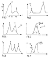
- FIG. 2 shows in a simplified manner a section of a spectral curve of a luminescent banknote BN actually measured with the test device 3, ie the dependence of the intensity I on the frequency f of the luminescence radiation.
- This spectral curve is formed by a larger number of measured values, not shown, and is characterized by two different sized maxima at frequencies f1 and f2.
- the maximum at the frequency f1 is caused by a first substance "a” and the second maximum at the frequency f2 is caused by a second substance "b", both in Mixture form the luminescent feature substance contained in the paper.
- FIG. 2 While in the prior art such a measurement curve would be displayed on the screen 10, the associated measurement values according to the invention are not forwarded for display on the screen 10. It is thus deliberately excluded that an actual trace accordingly FIG. 2 can be displayed in order to prevent the secrecy on the exact composition of the measured feature substances is compromised. Instead, measured values altered by a mathematical algorithm are forwarded as disguised cover data via the interface 9 and displayed on the screen 10 as a fogged spectral curve 11.
- FIG. 3 shows a very simple example that camouflage data are formed by changing the assignment of the measurement intensities to the frequencies.
- the camouflage data are of the same physical size as the measured values, ie also the camouflage data are like the actual measured values data to frequency-dependent intensity values.
- a concealment of the assignment of the intensity values to the frequencies ensues for concealment.
- the position of the maxima of the substances a and b in the considered frequency spectrum is reversed and the distance of the maxima is increased.
- the measurement intensities and the frequencies could also be mixed much more complex.
- the intensities at 50 measured frequencies f1, f2, f3, f4, ... f50 are assigned to the frequencies f13, f19, f7, f2, etc., in particular at a large number of measured frequencies (in example 50) suitable permutations, e.g. obtained at least partial aspects of the functional relationships, the frequencies of a complete mixing are preferable.
- FIG. 4 shows a second example of a measurement according to FIG. 2 associated Tarnkurve 11, which is formed by camouflage data, which are forwarded by the test device 3.
- the formation of the displayed camouflage data takes place by a different scaling of different measured values.
- the relative maxima of the substance "b" are normalized to the value of the absolute maximum of the spectral curve caused by the substance "a". This concept makes it possible to check the principle presence of the substances a and b despite the display of the caravan.
- FIG. 5 shows a third example of a measurement according to FIG. 2 This case is distinguished by the fact that the camouflage data are formed by superimposing the spectral curves in the regions around the relative maxima of the substances a and b at the frequencies f1 and f2.
- the course of the camouflage curve is exemplarily formed by the sum of the measured values scaled by the factor 4/5.
- FIG. 6 shows another example of a spectral curve measured by the test device 3.
- the measured values of this spectral curve are again not transmitted from the test device 3 to the display on the screen 10.
- the spectral curve has three maxima for the substances a, b, c contained in the feature substance.
- FIG. 7 shows an example of a measurement FIG. 6
- This camouflage curve 11 is a combination of the previous examples and characterized both by a mixing, overlaying and different scaling of the measured values to form the illustrated camouflage curve.
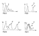
- FIG. 8 shows two actually measured by the tester 3 spectral curves.
- the solid line corresponds eg to a first coding a and the dashed line to a second coding b of a currency system.
- the different codes can for example consist in the use of different combinations of substances as feature substances and be used for example to denominate differentiation.
- the individual spectral curves However, a, b may also be different substances contained in combination in the audited banknote.
- FIG. 9 two associated Tarnkurven 11 are shown as an example, as they can be displayed on the screen 10.
- the individual spectral curves a, b are depicted as a single peak, wherein the distance of the individual peaks of the Tarndar ein is preferably constant.
- in the Tarndar ein also includes an indication of the measured amplitudes of the individual codes or substances a, b.
- a change in the total intensity of the individual actually measured spectral curves a, b of the FIG. 9 eg due to contamination in banknotes already in circulation, then resulting eg in a change in the size of the individual peaks of the camouflage curves 11.
- the checking device 3 will be designed to check the authenticity of the banknotes.
- the evaluation unit 6 will perform a genuineness classification of the bill. This can consist, for example, in that at least a distinction is made between genuine and false banknotes or between genuine, false, counterfeit, unrecognized banknotes.
- this classification can be a preliminary classification obtained only on the basis of the measured values of the test device 3, and e.g. only indicates whether the measured luminescence behavior corresponds to a genuine banknote.
- this classification may also be a final classification which also takes into account the measurements of other measurements made in the device 1, such as other optical, acoustic, magnetic and / or electrical measurements.
- the evaluation is carried out on the basis of the actually recorded measured values and not the camouflage data determined for display.
- the display of the stealth data may serve to provide certain information about real and false banknote measurements without compromising the secrecy of the actual spectral curves of genuine banknotes.
- FIGS. 10 and 11 show a further comparison of actual measuring curves (in Fig. 10 ) and associated camouflage curves 11 (in Fig. 11 ).
- the spectral curve e in FIG. 10 corresponds to the actual measurement curve of a genuine banknote, while the spectral curves x1, x2 correspond to actual measurement curves of two different counterfeits.
- the mathematical algorithm varies for different measured values and consists for example of several different partial algorithms and measured values are varied differently with different partial algorithms depending on whether the measured values fulfill at least one predetermined criterion.
- the measured values for forming the cover data will be changed by a locally continuous mathematical function.
- This local continuity means that small deviations in the measured values only lead to small deviations in the associated stealth data.
- This range can also be set to be e.g. also realistically covers the variations in the dosage of feature substances customary in paper and banknote production.
- the measured values are preferably changed more than within the range typical for real banknotes and e.g. be changed by a locally discontinuous mathematical function.
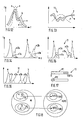
- FIG. 12 again shows actually measured spectral curves.
- the shaded area illustrates the tolerance range for the measured values of a banknote with two feature substances a and b, which is identified by the reference symbol "e” and which is classified as “genuine” by evaluating, inter alia, these measured values.
- With "x” the spectral curve of a forgery is shown, which contains only the feature substance a.
- the mathematical function for forming the camouflage data is designed only for measured values which lie within a predetermined tolerance range such that no two measured values are mapped to the same camouflage value. Outside the tolerance range, this requirement can even be purposefully violated, i. that in particular different measured values are mapped to the same camouflage value.
- forwarding and / or presentation of the cover data takes place only when the associated measured values fulfill at least one predetermined criterion.
- the cover data is displayed only if the checked banknote BN belongs to a certain class, specifically classified as "genuine".
- the cover data are then not forwarded or displayed by the checking device 3 for banknotes which have not been genuinely classified, such as the camouflage curve associated with the forgery x.
- a luminescent feature substance to be tested contains a plurality of different substances and / or individual peaks
- different types of deviations of the spectral measured values from the spectral nominal values, the substances or individual peaks are defined during the formation of the camouflage data and be taken into account.
- different changes of the measured values to form camouflage data are then preferably carried out.
- FIGS. 14 and 15 This concept is in the FIGS. 14 and 15 illustrated.
- a and b are in FIG. 14 illustrates the desired curves of the spectral curves of two different luminescent substances to be measured, which may be contained in combination in a banknote to be tested or separately eg in different codings.
- x1a, x2a, x1b, x2b the actually measured spectral curves of two other substances are shown, such as those contained in counterfeits.
- the spectral curves x1a and x2a or x1b and x2b differ by the measured intensity I of the luminescence radiation.
- camouflage curves 11 are shown, with corresponding camouflage curves are identified by the same reference numerals.
- FIG. 16 shows another example of camouflage curves 11 for FIG. 14 and illustrates the concept that a change in a measured quantity (intensity) results in a change in another size (frequency) of the cover data depending on the magnitude of this change.
- the other way of altering the measured data to form the cloaking data is that when there are deviations from the predetermined tolerance ranges, such as the tolerance ranges for real banknotes, changes in measured intensities of counterfeits classified as non-genuine x1a, x2a, x1b, x2b, moves the position of the associated camouflage curves.
- FIG. 17 shows two bar - shaped advertisements to camouflage data, as they also eg in the case of FIGS. 15 or 16 can be displayed on the screen 10.
- This display can be used, for example, to control the introduction of a luminescent feature substance from a plurality of substances into the paper or the printing ink of the banknote in the printing station 2.
- the scale line M1 in the upper bar indicates whether the mixing ratio of two substances of the sample corresponds to the ideal value (100%) or deviates therefrom.
- the scale line M2 in the lower bar indicates how large the contamination of the sample is by additional substances.
- the position of the scale marks M1, M2 is determined by evaluation of the measured spectral curves, eg FIG. 14 , won. Permitted tolerance ranges during production are indicated schematically by the hatched areas of the bars.
- Such a message after FIG. 17 is with a representation of spectral Tarnkurven such as after the FIGS. 15 or 16 coupled. It can, for example, then, if the contamination is outside the allowable tolerance range, the forwarding of the associated camouflage data or a graphical representation of the associated Tarnkurven also omitted.
- At least two different sets of camouflage data which are intended for different target groups, are formed for a measurement.
- the one cover data for example, is forwarded to an administrator of a set of checking devices 3 and the other cover data to the respective users of the individual checking devices 3.
- the data transfer and / or the display of the different cover data for different target groups preferably takes place only after a corresponding authentication of the respective target group.
- the nature of the formation of the cover data will differ in both cases, for example by using different tamper concepts previously explained with reference to the figures.
- an administrator has the in FIG. 13 displayed camouflage curves for all classified as genuine banknotes, while the usual user of the test equipment 3 only camouflage curves are displayed for a smaller tolerance range of all genuine banknotes.
- the information "real banknote” and only for a part of the genuinely classified banknotes the associated camouflage curves are displayed to this user.
- the cover data which are still classified as genuine, whose measured values have larger deviations from the ideal target values, are not displayed.
- the information displayed is e.g. also indicates in the form of a bar with what percentage the checked banknote was classified as "genuine". The percentage will then be e.g. indicate the extent to which the measured values, within the tolerance range permissible for genuinely classified banknotes, deviate from the ideal values of a genuine banknote.
- a 95% genuine bill is then sent e.g. still classified in the category "real", however, shows deviations from a reference measurement fixed reference measurement of a genuine banknote.
- the checking device 3 together with the camouflage data, forwards an individual checksum or any other code which may be e.g. is formed on the basis of the mathematical algorithm forming parameters and / or the associated measured values and due to the camouflage data can be recalculated to the associated measured values.
- the algorithm for reproducing the measured values with the aid of the camouflage data and the code will preferably be known only to the manufacturer of the test equipment 3, and may be known therefrom by e.g. can be used to check customer complaints due to possible incorrect evaluations or advertisements.
- camouflage can also be used for other measurements, such as time-varying measured values.
- time-resolved measured values for determining the decay times of the luminescence radiation can be camouflaged in the same way.
- the checking device 3 evaluates only a part of all recorded measured values for classifying the bank notes.
- test device 3 comprises e.g. a luminescence sensor for testing the luminescence radiation in the visible or infrared spectral range
- the evaluation of the presence of the luminescent feature substance and the representation of the associated camouflage curves will be based only on the measured values in the visible or infrared spectral range.
- the tolerance range for the Tarnaries reduced or renounced entirely on a visual representation of the cover data If, for example, the color impression or another authenticity criterion is not met or the tested forgery already does not fulfill further criteria.
- this criterion can be used e.g. also include an examination of whether the Lumineszenzmeßock for predetermined substances have characteristic properties.
- These predetermined substances are preferably per se substances not contained in the tested banknotes, but such as are e.g. Usually used for counterfeiting.
- the mentioned characteristic properties can e.g. concern the spectral course or the decay times of these known counterfeiting materials.
- the stealth data is then formed in other, more concealing manner and / or the Tambredarwolf is prevented when these characteristic properties are measured.
- the measured values represented as measuring vector are present as data points in an n-dimensional space M, for example the IR n , and are transformed into an m-dimensional space for camouflage, where m can be greater, smaller or equal to n.
- Different algorithms for camouflage can be used in this space for different classes, for example, depending on which target class i, which is defined for example by a target vector x i and an associated class area K i , is assigned the measurement vector. It is possible that there are areas where the measurement vector is not assigned to any destination class at all, ie the space IR n need not be completely divided into destination classes. In particular, there may additionally be a tolerance range Ti for each target class i, which lies within the class area Ki.
- the function (s) fi which are e.g. can also be defined only locally in M or the class areas Ki.
- a function f may be used that shows different behavior in different subranges of M.
- the function f (or functions fi) meet certain conditions. For example, it is possible that only the target vector xi is mapped to the camouflage value f (i) (xi).
- the function (s) is (are) such that no points outside a tolerance range Ti are mapped into the associated camouflage area f (Ti).
- the function (s) be chosen so that in a sequence of measured measurements yi converging to a setpoint xi, the camouflage values f (yi) also converge to the camouflaged setpoint f (xi), or / and conversely, a sequence of camouflage values f (yi) converging to f (xi) also corresponds to a sequence of measured values yi converging to xi.
- the functions f i may be chosen such that these restrictions outside the tolerance ranges Ti do not apply, and e.g. Measured values in the space M that are not within a tolerance range, are displayed in an area of the camouflage space that consciously dispenses with an unambiguous assignment.
Description
Die Erfindung betrifft eine Vorrichtung und ein Verfahren zur visuellen Darstellung von Meßwerten.The invention relates to a device and a method for the visual display of measured values.
Obwohl nicht darauf beschränkt, betrifft die Erfindung im speziellen auch Vorrichtungen und Verfahren zur Prüfung von Wertdokumenten, wie z.B. Systeme zur Prüfung der Echtheit und/oder des Nennwerts von Wertdokumenten, bei denen Meßwerte der Wertdokumente aufgenommen und Prüfergebnisse visuell dargestellt werden. Solche Wertdokumente können z.B. Banknoten, Schecks, Chipkarten, Ausweise, Pässe oder dergleichen sein.Although not limited thereto, the invention also specifically relates to apparatus and methods for checking value documents, such as e.g. Systems for checking the authenticity and / or denomination of value documents, in which measured values of the value documents are recorded and test results are visually displayed. Such value documents may e.g. Banknotes, checks, chip cards, ID cards, passports or the like.
Zur Prüfung der von einem Wertdokumenten ausgehenden Lumineszenzstrahlung, wie z.B. von Phosphoreszenz- oder Fluoreszenzstrahlung, werden üblicherweise Systeme eingesetzt, wie sie in der
Unter einem lumineszierenden Merkmalsstoff wird ein Stoff aus einer einzelnen Komponente oder einer Mischung von mehreren Komponenten verstanden, die ein Lumineszenzverhalten zeigen. Diese Merkmalsstoffe, welche z.B. in Form von Pigmenten vorliegen können, sind im Wertdokument selbst enthalten und/oder auf dieses aufgebracht. Die Merkmalsstoffe können z.B. auch in räumlich codierter Form aufgebracht sein, um unterschiedliche Nennwerte eines Währungssystems unterscheiden zu können.A luminescent feature substance is understood as meaning a substance composed of a single component or of a mixture of a plurality of components which exhibit a luminescence behavior. These feature substances, which may be present for example in the form of pigments, are contained in the value document itself and / or applied to it. The feature substances may, for example, also be applied in spatially coded form in order to be able to differentiate between different denominations of a monetary system.
Um Fälschern das Erstellen von gefälschten Banknoten zu erschweren wird versucht, Informationen über die genaue Zusammensetzung und die charakteristischen spektralen Eigenschaften der lumineszierenden Merkmalsstoffe, welche von den Lumineszenzsensoren gemessen werden, geheim zu halten.To make it difficult for counterfeiters to create counterfeit banknotes, it is attempted to keep information about the exact composition and the characteristic spectral properties of the luminescent feature substances measured by the luminescence sensors secret.
Ein bewährtes Konzept zur Geheimhaltung dieser Informationen ist es, daß auch die zugehörigen Lumineszenzsensoren so gesichert werden müssen, daß sie keine Meßwerte nach außen geben.A proven concept for keeping this information secret is that also the associated luminescence sensors must be secured in such a way that they do not give any measured values to the outside.
Hierzu wird z.B. der Lumineszenzsensor mit seiner Auswertungselektronik in einem vor Zugriff gesicherten geschlossenen Gehäuse montiert. Die Auswertungselektronik dient dazu, die aufgenommenen Meßwerte auszuwerten. Das Ergebnis der Auswertung der jeweiligen Banknote kann z.B. in einer Klassifizierung der Banknote in eine der Kategorien "echte", "falsche", "fälschungsverdächtige" oder "nicht erkannte" Banknote bestehen.For this purpose, e.g. the luminescence sensor mounted with its evaluation electronics in a secured against access closed housing. The evaluation electronics serves to evaluate the recorded measured values. The result of the evaluation of the respective banknote can be e.g. in a classification of the banknote into one of the categories "genuine", "false", "suspected counterfeit" or "unrecognized" banknote.
Das Gehäuse weist dabei eine Schnittstelle zur Übermittlung von Daten an eine externe Einheit, wie z.B. an eine Steuerungseinheit eines Geldautomaten oder einer Banknotensortiervorrichtung auf, in welchem bzw. welcher der Lumineszenzsensor integriert ist. Die Steuerungseinheit ist üblicherweise mit einer Anzeige verbunden, an der dem Bediener des Geldautomaten bzw. der Banknotensortiervorrichtung Informationen über das Ergebnis der Prüfung angezeigt, d.h. visuell dargestellt werden. Von besonderem Interesse ist die Übermittlung von Daten an eine externe Einheit, wie z.B. eine nachgeschaltete Datenauswerteeinheit bzw. die Anzeige eines Qualitätskontrollgeräts, das zur Qualitätsprüfung der Banknote bei oder nach ihrer Herstellung eingesetzt wird. Gerade in diesem Fall ist es von Interesse bzw. sogar erforderlich, außer der Intensität des Merkmals zusätzliche Informationen über das Merkmal dem Anwender zur Verfügung zu stellen, damit die Produktion innerhalb vorgegebener Toleranzen durchgeführt werden kann. Alternativ kann der Produktion nachgeschaltet auch eine Überprüfung vorgegebener Toleranzen erfolgen, die mehr als lediglich z.B. die Intensität des Lumineszenzstoffes bewertet.In this case, the housing has an interface for the transmission of data to an external unit, such as, for example, to a control unit of an ATM or a banknote sorting device, in which or which the luminescence sensor is integrated. The control unit is usually connected to a display at which the operator of the ATM or the banknote sorting device information about the result of the test are displayed, ie displayed visually. Of particular interest is the transmission of data to an external unit, such as a downstream data evaluation unit or the display of a quality control device that is used for quality control of the bill during or after its production. Especially in this case, it is of interest or even necessary to provide the user with additional information about the feature in addition to the intensity of the feature, so that the production can be performed within predetermined tolerances. Alternatively, downstream of the production, a check of predetermined tolerances can take place, which evaluates more than merely, for example, the intensity of the luminescent substance.
Wesentlich ist, daß über die Schnittstelle des Lumineszenzsensors keine Meßdaten an die externe Einheit übermittelt werden. Es werden lediglich die Klassifizierungsergebnisse selbst (echte, falsche, fälschungsverdächtige, nicht erkannte Banknote) vom Banknotensensor an die externe Einheit weitergeben und angezeigt.It is essential that no measurement data is transmitted to the external unit via the interface of the luminescence sensor. Only the classification results themselves (real, false, counterfeit, unrecognized banknote) are passed from the banknote sensor to the external unit and displayed.
Da somit ein berechtigter oder auch unberechtigter Benutzer des Lumineszenzsensors prinzipiell keine Informationen über die eigentlichen Meßwerte der Banknoten erhält, sind keine Rückschlüsse auf die lumineszierenden Merkmalsstoffe möglich. Hierdurch kann eine Geheimhaltung von Informationen über die lumineszierenden Merkmalsstoffe sicher gewährleistet werden.Since an authorized or even unauthorized user of the luminescence sensor therefore in principle does not receive any information about the actual measured values of the banknotes, no conclusions can be drawn about the luminescent feature substances. In this way, secrecy of information about the luminescent feature substances can be reliably ensured.
Nun gibt es allerdings in der letzten Zeit auch Lumineszenzsensoren für Banknoten, die mit einer analogen Schnittstelle zur Weiterleitung von Meßwerten der gemessenen Lumineszenzstrahlung an eine externe Einheit ausgerüstet sind. Zur Qualitätskontrolle bei der Papier- bzw. Banknotenherstellung werden dann an einem Bildschirm der externen Einheit graphische Darstellungen der Spektralkurven selbst angezeigt.However, luminescence sensors for bank notes which are equipped with an analog interface for forwarding measured values of the measured luminescence radiation to an external unit have recently been available. For quality control in the production of paper or banknotes, graphic representations of the spectral curves themselves are then displayed on a screen of the external unit.
Somit können Personen, welche die Lumineszenzsensoren benutzen, durch die visuelle Darstellung Informationen über die Meßwerte selbst oder daraus abgeleitete Größen, wie z.B. über die gemessenen Spektralkurven der lumineszierenden Merkmalsstoffe erhalten. Hierdurch werden Rückschlüsse auf die lumineszierenden Merkmalsstoffe möglich gemacht, die im Prinzip auch mißbräuchlich zur Nachbildung der Merkmalsstoffe benutzt werden können.Thus, persons using the luminescence sensors may, through the visual representation, provide information about the measurements themselves or quantities derived therefrom, e.g. obtained via the measured spectral curves of the luminescent feature substances. This makes it possible to draw conclusions about the luminescent feature substances which, in principle, can also be used abusively to simulate the feature substances.
Davon ausgehend ist es die Aufgabe der vorliegenden Erfindung, eine Vorrichtung und ein Verfahren zur visuellen Darstellung von Meßwerten, insbesondere bei der Prüfung von Wertdokumenten, zur Verfügung zu stellen, welche die vorstehend genannten Nachteile vermeiden.On this basis, it is the object of the present invention to provide an apparatus and a method for the visual representation of measured values, in particular in the examination of value documents, which avoid the disadvantages mentioned above.
Diese Aufgabe wird durch die unabhängigen Ansprüche gelöst. Die abhängigen Ansprüche und die nachfolgende Beschreibung erläutern bevorzugte Ausgestaltungen.This object is solved by the independent claims. The dependent claims and the following description illustrate preferred embodiments.
Die vorliegende Erfindung geht somit von der Idee aus, die visuelle Darstellung von Echtheitsdaten oder sonstigen Meßwerten dadurch zu verschleiern, daß nicht die Meßwerte selbst, sondern Tarndaten visuell dargestellt werden, die durch mit Hilfe eines mathematischen Algorithmus veränderte Meßwerte gebildet werden.The present invention is thus based on the idea of obscuring the visual representation of authenticity data or other measured values by visually displaying not the measured values themselves, but camouflage data which are formed by measured values changed with the aid of a mathematical algorithm.
Die Vorteile dieses Tarnkonzepts zeigen sich besonders deutlich bei der bevorzugten Anwendung der Prüfung von Wertdokumenten, insbesondere bei der Prüfung der Lumineszenzstrahlung von Sicherheitspapier bzw. Banknoten.The advantages of this camouflage concept are particularly evident in the preferred application of the examination of value documents, in particular in the examination of the luminescence radiation of security paper or banknotes.
Wie erwähnt werden beim zuletzt beschriebenen bekannten Sensorkonzept mittels einer Analogschnittstelle Meßwerte an einen externen Überwachungsplatz übertragen, an dem dann beispielsweise die gemessenen Spektralkurven der lumineszierenden Merkmalsstoffe angezeigt werden.As mentioned, in the case of the previously described known sensor concept, measured values are transmitted to an external monitoring station by means of an analog interface, at which point, for example, the measured spectral curves of the luminescent feature substances are displayed.
Im Gegensatz dazu können gemäß der vorliegenden Erfindung z.B. nur Tarndaten angezeigt werden, die durch eine Veränderung der Meßwerte entstanden sind und mit den eigentlichen Meßwerten variieren. Werden beim Stand der Technik die tatsächlich gemessenen Spektralkurven angezeigt, werden gemäß der vorliegenden Erfindung beispielsweise veränderte Spektralkurven mit veränderten Intensitätsverhältnissen angezeigt.In contrast, according to the present invention, e.g. Only camouflage data are displayed, which are caused by a change in the measured values and vary with the actual measured values. If the actually measured spectral curves are displayed in the prior art, modified spectral curves with altered intensity ratios are displayed according to the present invention, for example.
Wie noch erläutert wird, kann somit durch eine Analyse der visuellen Darstellung der Tarndaten zwar auch eine Qualitätskontrolle oder dergleichen erleichtert werden, es sind aber keine direkten Rückschlüsse auf die die Lumineszenzstrahlung verursachenden lumineszierenden Merkmalsstoffe der Banknoten möglich.As will be explained, a quality control or the like can thus be facilitated by an analysis of the visual representation of the camouflage data, but there are no direct conclusions as to the luminescent feature substances of the banknotes causing the luminescence radiation.
Mit anderen Worten ermöglicht das erfindungsgemäße Konzept der Tarnung der Meßwerte somit deutlich besser als das bekannte Sensorkonzept mit Analogschnittstelle eine Geheimhaltung der lumineszierenden Merkmalsstoffe, obwohl der Nutzer des Sensors gleichzeitig auch ein gewisses Maß an Informationen über die Messungen erhält, die er beispielsweise zur Qualitätssicherung nutzen kann.In other words, the inventive concept of disguising the measured values thus significantly better secures the secrecy of the luminescent feature substances than the known sensor concept with analog interface, although the user of the sensor simultaneously also receives a certain amount of information about the measurements, which he can use, for example, for quality assurance ,
Je nach Anwendungsfall kann die Tarnung unterschiedlich erfolgen. D.h. wenn es z.B. bei der Qualitätsprüfung bevorzugt um eine Prüfung der Spektralamplituden geht, sind diese so darzustellen, daß die für die Qualitätsbeurteilung notwendigen Rückschlüsse auf die Amplituden noch möglich sind. Die Form der einzelnen Spektralkurven, die Reihenfolge der Spektralamplituden oder deren Abstand zueinander etc. kann aber beliebig verfremdet werden.Depending on the application, the camouflage can be done differently. That if it is e.g. In the quality test preferred to a check of the spectral amplitudes, they are to be displayed so that the necessary conclusions for the quality assessment on the amplitudes are still possible. However, the shape of the individual spectral curves, the order of the spectral amplitudes or their distance from one another, etc. can be alienated as desired.
Soll dagegen in einem anderen Anwendungsfall z.B. primär geprüft werden, ob bestimmte Stoffe, z.B. in einem Wertdokument, vorhanden sind, ist es wichtig diesem Sachverhalt zu betonen, d.h. für jeden Stoff eine zugehörige Kurve darzustellen. Bei dieser Tarndarstellung können die Amplituden z.B. gleich hoch wiedergegeben werden, obwohl diese in der Realität verschieden sind. Hierdurch können Rückschlüsse auf die Intensität vermieden werden.If, on the other hand, in another application, e.g. primarily to check whether certain substances, e.g. in a value document, it is important to emphasize this fact, i. to show an associated curve for each substance. In this view, the amplitudes may be e.g. even though they are different in reality. As a result, conclusions about the intensity can be avoided.
Je nach Anwendungsfall werden somit nur für diesen Anwendungsfall notwendige Daten angezeigt, während andere Daten nicht angezeigt werden.Depending on the application, only necessary data for this application are displayed, while other data are not displayed.
Bevorzugt können auch zur Prüfung der selben Stoffe zu unterschiedlichen Anwendungen unterschiedliche Tarndarstellungen gewählt werden. Dies führt dazu, daß eine Person, die zu unterschiedlichen Anwendungen Zugang hat, daraus keinen Nutzen ziehen kann. Mit anderen Worten werden die mathematischen Algorithmen bei unterschiedlichen Anwendungen so variieren, daß bei unterschiedlichen Messungen die Tarndaten zum selben Prüfgegenstand auch bei identischen Meßwerten varüeren.Preferably also different Tarndarstellungen can be selected to test the same substances for different applications. As a result, a person who has access to different applications can not benefit from it. In other words, in different applications, the mathematical algorithms will vary so that, for different measurements, the cover data for the same test object will vary, even with identical measured values.
Weitere Vorteile der vorliegenden Erfindung ergeben sich aus den abhängigen Ansprüchen sowie der nachfolgenden Beschreibung von Ausführungsbeispielen anhand der beigefügten Figuren.Further advantages of the present invention will become apparent from the dependent claims and the following description of embodiments with reference to the accompanying figures.
Es sei besonders betont, daß die Merkmale der abhängigen Ansprüche und der in der nachstehenden Beschreibung genannten Ausführungsbeispiele in Kombination oder auch unabhängig voneinander und vom Gegenstand der Hauptansprüche vorteilhaft verwendet werden können.It should be particularly emphasized that the features of the dependent claims and the embodiments mentioned in the following description can be used advantageously in combination or independently of one another and from the subject matter of the main claims.
Dabei zeigen die
- Figur 1
- eine schematische Ansicht auf eine Prüfeinrichtung für Banknoten;
Figur 2- einen Ausschnitt einer mit der Prüfeinrichtung gemessenen Spektralkurve;
Figur 3- eine erste visuelle Darstellung von Tarndaten zur Spektralkurve der
Figur 2 - Figur 4
- eine zweite visuelle Darstellung von Tarndaten zur Spektralkurve der
Figur 2 Figur 5- eine dritte visuelle Darstellung von Tarndaten zur Spektralkurve der
Figur 2 Figur 6- einen Ausschnitt einer anderen mit der Prüfeinrichtung gemessenen Spektralkurve;
- Figur 7
- eine visuelle Darstellung von Tarndaten zur Spektralkurve der
Figur 6 - Figur 8
- einen Ausschnitt zweier mit der Prüfeinrichtung gemessener Spektralkurven von zwei Codierungen eines Währungssystems;
Figur 9- eine visuelle Darstellung von zwei Tarnkurven zu den beiden Spektralkurven der
Figur 8 ; Figur 10- einen Ausschnitt auf drei mit der Prüfeinrichtung gemessenen Spektralkurven einer echten Banknote und zweier Fälschungen;
Figur 11- eine visuelle Darstellung von drei Tarnkurven zu den drei Spektralkurven der
Figur 10 ; Figur 12- einen Ausschnitt auf den Toleranzbereich von als echt klassifizierten mit der Prüfeinrichtung gemessenen Spektralkurven und auf eine Spektralkurve einer Fälschung;
- Figur 13
- eine visuelle Darstellung von Tarnkurven zu den
Spektralkurven der Figur 12 ; - Figur 14
- einen Ausschnitt auf mehrere mit der Prüfeinrichtung gemessene Spektralkurven von Banknotenmerkmalsstoffen und von nicht in Banknoten enthaltenen anderen Stoffen;
- Figur 15
- eine visuelle Darstellung von Tarnkurven zu den Spektralkurven der
Figur 14 ; - Figur 16
- eine andere visuelle Darstellung von Tarnkurven zu den Spektralkurven der
Figur 14 ; - Figur 17
- eine visuelle Darstellung von Informationsbalken zur Qualitätsprüfung bei der Herstellung von Wertdokumenten und
- Figur 17
- eine visuelle Darstellung zur Bildung der Tarndaten aus den Meßwerten.
- FIG. 1
- a schematic view of a test device for banknotes;
- FIG. 2
- a section of a spectral curve measured by the test device;
- FIG. 3
- a first visual representation of stealth data for the spectral curve of
FIG. 2 ; - FIG. 4
- a second visual representation of stealth data for the spectral curve of the
FIG. 2 ; - FIG. 5
- a third visual representation of camouflage data for the spectral curve of
FIG. 2 ; - FIG. 6
- a section of another spectral curve measured by the tester;
- FIG. 7
- a visual representation of stealth data for the spectral curve of the
FIG. 6 ; - FIG. 8
- a section of two spectral curves of two codings of a currency system measured with the test device;
- FIG. 9
- a visual representation of two camouflage curves to the two spectral curves of the
FIG. 8 ; - FIG. 10
- a section on three measured with the test device spectral curves of a genuine banknote and two counterfeits;
- FIG. 11
- a visual representation of three camouflage curves to the three spectral curves of the
FIG. 10 ; - FIG. 12
- a section on the tolerance range of spectral curves measured as genuinely classified with the test device and on a spectral curve of a forgery;
- FIG. 13
- a visual representation of camouflage curves to the spectral curves of the
FIG. 12 ; - FIG. 14
- a section on several measured with the test facility spectral curves of banknote feature substances and other substances not contained in banknotes;
- FIG. 15
- a visual representation of camouflage curves to the spectral curves of the
FIG. 14 ; - FIG. 16
- another visual representation of camouflage curves to the spectral curves of the
FIG. 14 ; - FIG. 17
- a visual representation of information bars for quality control in the production of value documents and
- FIG. 17
- a visual representation of the formation of the cover data from the measured values.
Obwohl nicht darauf beschränkt, wird im folgenden vor allem auf die Prüfung von Banknoten oder anderen Wertdokumenten eingegangen, die mit lumineszierenden Merkmalsstoffen versehen sind. Die lumineszierenden Merkmalsstoffe können z.B. im Banknoten-Papier selbst eingebracht und/oder aufgedruckt sein. Sensoren zur Messung solcher Merkmalsstoffe können z.B. in Papierherstellungs-, Banknotendruck-, Banknotenzähl- bzw. - Banknotensortier-, Banknoteneinzahl-, Banknotenauszahlvorrichtungen, Verkaufsautomaten oder in anderen Banknotenbearbeitungsvorrichtungen eingesetzt werden.Although not limited thereto, the following will focus in particular on the examination of banknotes or other value documents provided with luminescent feature substances. The luminescent feature substances can e.g. be inserted and / or printed in the banknote paper itself. Sensors for measuring such feature substances may e.g. in papermaking, banknote printing, banknote counting, banknotes, bill dispensers, vending machines, or other banknote processing devices.
Die Prüfeinrichtung 3 dient dabei insbesondere zur Lumineszenzprüfung von in der Druckfarbe enthaltenen lumineszierenden Merkmalsstoffen und umfaßt dazu eine Beleuchtungseinheit 4, um die zu prüfenden Banknoten BN zu beleuchten, ein Spektrometer als Sensoreinheit 5 zur spektral aufgelösten Erfassung der von der beleuchteten Banknote BN ausgehenden Lumineszenzstrahlung und eine mit der Beleuchtungseinheit 4 und der Sensoreinheit 5 verbundene EDV-gestützte Auswertungseinheit 6, um die durch die Sensoreinheit 5 erfaßten Signale auszuwerten.The
Die Auswertungseinheit 6 ist vorzugsweise mit der Sensoreinheit 5 in einem gemeinsamen Gehäuse 7 angebracht. Die Auswertungseinheit 6 kann allerdings auch ein separates Bauteil sein, daß über eine Datenleitung mit der Beleuchtungseinheit 4 und der Sensoreinheit 5 verbunden ist.The
Das Gehäuse 7 ist vor unerlaubtem Zugriff gesichert und weist eine Schnittstelle 9 auf, um Daten von der Prüfeinrichtung 3 an einen Steuerungsrechner 8 zu übertragen, der die Bearbeitungsvorrichtung 1 in Abhängigkeit u.a. der Auswertungsergebnisse der Prüfeinrichtung 3 steuert und z.B. Banknoten BN mit mangelhafter Druckqualität markiert bzw. aussortiert.The housing 7 is secured against unauthorized access and has an
Der Steuerungsrechner 8 ist dabei mit einem Bildschirm 10 verbunden, auf dem von der Prüfeinrichtung 3 übermittelte Daten zur jeweiligen Messung angezeigt werden (Kurve 11). Die angezeigten Daten können von einer Bedienperson dazu verwendet werden, die Vorrichtung 1 mittels einer Eingabeeinheit 12 zu regeln. Diese Regelung kann allerdings auch automatisch erfolgen. Die Regelung kann z.B. darin bestehen, daß in der Druckstation 2 die Dosierung der lumineszierenden Merkmalsstoffe in der Druckfarbe geändert wird.The control computer 8 is connected to a
Ausgezeichnet ist die Vorrichtung 1 durch die Art der Daten, welche über die Schnittstelle 9 von der Prüfeinrichtung 3 bzw. der Auswerteeinheit 6 zur Anzeige auf dem Bildschirm 10 übertragen werden. Über die Schnittstelle 9 werden keine Meßwerte, sondern Tarndaten übertragen. Die Tarndaten sind dadurch gebildet, daß in der Auswertungseinheit 6 mit Hilfe eines mathematischen Algorithmus die tatsächlichen Meßwerte verändert werden. Anhand der nachfolgenden Figuren wird dieses Konzept an mehreren Beispielen näher erläutert, wobei die einzelnen Beispiele auch miteinander kombiniert werden können.Excellent is the device 1 by the type of data which are transmitted via the
Während beim Stand der Technik eine derartige Meßkurve auf dem Bildschirm 10 dargestellt würde, werden die zugehörigen Meßwerte gemäß der Erfindung gerade nicht zur Darstellung auf dem Bildschirm 10 weitergeleitet. Es wird somit bewußt ausgeschlossen, daß eine tatsächliche Meßkurve entsprechend
Die
Die Meßintensitäten und die Frequenzen könnte allerdings auch wesentlich komplexer vermischt sein. So können z.B. die Intensitäten bei 50 gemessenen Frequenzen f1, f2, f3, f4,... f50 den Frequenzen f13, f19, f7, f2 etc. zugewiesen werden, wobei insbesondere bei einer großen Zahl gemessener Frequenzen (im Beispiel 50) geeignete Permutationen, die z.B. wenigstens Teilaspekte der funktionalen Zusammenhänge erhalten, der Frequenzen einer völligen Durchmischung vorzuziehen sind.However, the measurement intensities and the frequencies could also be mixed much more complex. Thus, e.g. the intensities at 50 measured frequencies f1, f2, f3, f4, ... f50 are assigned to the frequencies f13, f19, f7, f2, etc., in particular at a large number of measured frequencies (in example 50) suitable permutations, e.g. obtained at least partial aspects of the functional relationships, the frequencies of a complete mixing are preferable.
Der Verlauf der Tarnkurve ist exemplarisch gebildet durch die Summe der Meßwerte skaliert um den Faktor 4/5.The course of the camouflage curve is exemplarily formed by the sum of the measured values scaled by the factor 4/5.
In der
In
Zusätzlich kann vorgesehen sein, daß in der Tarndarstellung auch eine Anzeige über die gemessenen Amplituden der einzelnen Codierungen bzw. Stoffe a, b umfaßt. So kann eine Änderung der Gesamtintensität der einzelnen tatsächlich gemessenen Spektralkurven a, b der
Insbesondere in den Fällen, in denen die Prüfeinrichtung 3 z.B. in Zentralbanken, Cash Centern oder Geldeinzahlautomaten zur Prüfung von bereits umgelaufenen Banknoten eingesetzt wird, wird die Prüfeinrichtung 3 zur Echtheitsprüfung der Banknoten ausgelegt sein. In einem solchen Fall wird die Auswertungseinheit 6 eine Echtheits-Klassifizierung der Banknote durchführen. Diese kann z.B. darin bestehen, daß zumindest zwischen echten und falschen Banknoten bzw. zwischen echten, falschen, fälschungsverdächtigen, nicht erkannten Banknoten unterschieden wird.In particular, in the cases in which the
Diese Klassifizierung kann zum einen eine vorläufige Klassifizierung sein, die nur auf der Grundlage der Meßwerte der Prüfeinrichtung 3 gewonnen wird und z.B. nur angibt, ob das gemessene Lumineszenzverhalten einer echten Banknote entspricht. Diese Klassifizierung kann allerdings auch eine abschließende Klassifizierung sein, welche auch die Meßwerte von anderen in der Vorrichtung 1 durchgeführten Messungen, wie anderer optischer, akustischer, magnetischer und/oder elektrischer Messungen berücksichtigt.On the one hand, this classification can be a preliminary classification obtained only on the basis of the measured values of the
Die Auswertung wird dabei auf der Grundlage der tatsächlich aufgenommenen Meßwerte und nicht der daraus gewonnenen zur Anzeige bestimmten Tarndaten durchgeführt werden. Die Anzeige der Tarndaten kann allerdings dazu dienen, gewisse Informationen über die Messungen von echten und falschen Banknoten anzugeben, ohne gleichzeitig die Geheimhaltung der tatsächlichen Spektralkurven echter Banknoten zu kompromittieren.The evaluation is carried out on the basis of the actually recorded measured values and not the camouflage data determined for display. The display of the stealth data, however, may serve to provide certain information about real and false banknote measurements without compromising the secrecy of the actual spectral curves of genuine banknotes.
Die
In der zugehörigen Tarndarstellung der
Dies kann z.B. erfolgen, indem die Meßkurven so überlagert werden, daß die absoluten Maxima aller Meßkurven, d.h. sowohl der echten Banknoten, als auch der Fälschungen übereinander abgebildet werden. Dies erfolgt sinnvollerweise durch unterschiedliche farbige Darstellungen. Optional können zusätzlich auch die vorherstehend genannten weiteren Tarnvarianten z.B. der unterschiedlichen Skalierung und Vermischung der Meßwerte eingesetzt werden.This can e.g. be done by superimposing the traces so that the absolute maxima of all traces, i. e. Both the real banknotes, as well as the counterfeits are displayed on top of each other. This is done usefully by different colored representations. Optionally, in addition, the above-mentioned further camouflage variants, e.g. the different scaling and mixing of the measured values are used.
Nach einer weiteren Idee der vorliegenden Erfindung kann vorgesehen sein, daß der mathematische Algorithmus für unterschiedliche Meßwerte variiert und beispielsweise aus mehreren unterschiedlichen Teilalgorithmen besteht und Meßwerte in Abhängigkeit davon, ob die Meßwerte zumindest ein vorgegebenes Kriterium erfüllen, mit unterschiedlichen Teilalgorithmen unterschiedlich verändert werden.According to a further idea of the present invention, it can be provided that the mathematical algorithm varies for different measured values and consists for example of several different partial algorithms and measured values are varied differently with different partial algorithms depending on whether the measured values fulfill at least one predetermined criterion.
Dies bedeutet, daß z.B. bei einer Echtheits- oder Qualitätskontrolle von Wertdokumenten eine Unterscheidung getroffen werden kann, ob die Meßwerte in einem vorgegebenen zu erwartenden Toleranzbereich liegen oder zu stark von den Werten echter Banknoten abweichen.This means that e.g. In the case of an authenticity or quality control of value documents, a distinction can be made as to whether the measured values lie within a predefined, expected tolerance range or differ too greatly from the values of genuine banknotes.
Insbesondere in dem Fall, daß die Meßwerte innerhalb des für echte Banknoten typischen Bereichs liegen, werden die Meßwerte zur Bildung der Tarndaten durch eine lokal stetige mathematische Funktion verändert werden. Diese lokale Stetigkeit bedeutet, daß kleine Abweichungen in den Meßwerten nur zu kleinen Abweichungen in den zugehörigen Tarndaten führen. Somit ist zumindest in diesem z.B. für echte Banknoten beschränkten Meßwertebereich eine gewisse Nachvollziehbarkeit der Auswirkungen z.B. von Intensitätsschwankungen des Spektrums auf die dargestellten Tarnkurven möglich.In particular, in the case that the measured values are within the range typical for real notes, the measured values for forming the cover data will be changed by a locally continuous mathematical function. This local continuity means that small deviations in the measured values only lead to small deviations in the associated stealth data. Thus, at least in this example for real banknotes limited range of measurements a certain traceability of the effects such as intensity fluctuations of the spectrum on the camouflage curves shown possible.
Dieser Bereich kann auch so festgelegt werden, daß er z.B. auch die bei der Papier- bzw. Banknotenherstellung üblichen Schwankungen in der Dosierung der Merkmalsstoffe realistisch abdeckt.This range can also be set to be e.g. also realistically covers the variations in the dosage of feature substances customary in paper and banknote production.
Wenn allerdings die Meßwerte außerhalb des z.B. für echte Banknoten typischen Bereichs liegen, werden die Meßwerte vorzugsweise stärker verändert werden als innerhalb des für echte Banknoten typischen Bereichs und z.B. durch eine lokal unstetige mathematische Funktion verändert werden.However, if the readings outside the e.g. For real banknotes typical range, the measured values are preferably changed more than within the range typical for real banknotes and e.g. be changed by a locally discontinuous mathematical function.
Somit sind keine Rückschlüsse möglich inwieweit die echten und die falschen Stoffe zueinander in Beziehung stehen.Thus, no conclusions are possible to what extent the real and the wrong substances are related to each other.
In den
In
Da bei der Anzeige der beiden Kurven jede Ähnlichkeit fehlt, kann auch nicht zurückgeschlossen werden, daß die Stoffe eine gewisse Ähnlichkeit aufweisen.Since there is no similarity in the display of the two curves, it can not be concluded that the substances have a certain similarity.
Alternativ oder zusätzlich kann auch vorgesehen sein, daß die mathematische Funktion zur Bildung der Tarndaten nur für Meßwerte, die in einem vorgegebenen Toleranzbereich liegen, so ausgestaltet ist, daß keine zwei Meßwerte auf denselben Tarnwert abgebildet werden. Außerhalb des Toleranzbereichs kann diese Forderung sogar zielgerichtet verletzt werden, d.h. daß insbesondere verschiedene Meßwerte auf den gleichen Tarnwert abgebildet werden.Alternatively or additionally, it may also be provided that the mathematical function for forming the camouflage data is designed only for measured values which lie within a predetermined tolerance range such that no two measured values are mapped to the same camouflage value. Outside the tolerance range, this requirement can even be purposefully violated, i. that in particular different measured values are mapped to the same camouflage value.
Es kann auch vorgesehen sein, daß eine Weiterleitung und/oder Darstellung der Tarndaten nur dann erfolgt, wenn die zugehörigen Meßwerte zumindest ein vorgegebenes Kriterium erfüllen. Insbesondere ist es von Vorteil, falls die Tarndaten nur dann angezeigt werden, wenn die geprüfte Banknote BN als einer bestimmten Klasse zugehörig, im speziellen als "echt" klassifiziert wird. Beim Beispiel der
Vorzugsweise in dem Fall, daß ein zu prüfender lumineszierender Merkmalsstoff mehrere unterschiedliche Stoffe und/oder Einzelpeaks enthält, kann auch vorgesehen sein, daß bei der Bildung der Tarndaten unterschiedliche Arten der Abweichungen der spektralen Meßwerte von den spektralen Sollwerten, der Stoffe bzw. Einzelpeaks, festgelegt und berücksichtigt werden. Je nach Art der Abweichung werden dann vorzugsweise unterschiedliche Veränderungen der Meßwerte zur Bildung von Tarndaten durchgeführt werden.In the case where a luminescent feature substance to be tested contains a plurality of different substances and / or individual peaks, it may also be provided that different types of deviations of the spectral measured values from the spectral nominal values, the substances or individual peaks, are defined during the formation of the camouflage data and be taken into account. Depending on the type of deviation, different changes of the measured values to form camouflage data are then preferably carried out.
Dieses Konzept ist in den
In der
Während bei in der Umgebung des Peaks a liegenden Meßwerten bei größeren Frequenzen auch die zugehörigen Tarndaten bei größeren Werten erscheinen, ist diese Beziehung bei in der Umgebung des Peaks b liegenden Meßwerten umgekehrt und die Tarndaten erscheinen in der
Exemplarisch gibt der Skalenstrich M1 im oberen Balken an, ob das Mischungsverhältnis von zwei Stoffen der Probe dem Idealwert (100%) entspricht oder davon abweicht. Der Skalenstrich M2 im unteren Balken gibt an, wie groß die Verunreinigung der Probe durch zusätzliche Substanzen ist. Die Position der Skalenstriche M1, M2 wird durch Auswertung der gemessenen Spektralkurven, z.B. nach
Eine solche Anzeige nach
Nach einer weiteren Idee der vorliegenden Erfindung werden zu einer Messung zumindest zwei unterschiedliche Mengen von Tarndaten gebildet, die für unterschiedliche Zielgruppen bestimmt sind. Die einen Tarndaten werden z.B. einem Administrator einer Menge von Prüfeinrichtungen 3 und die anderen Tarndaten den jeweiligen Benutzern der einzelnen Prüfeinrichtungen 3 zugeleitet. Die Datenübermittlung und/oder die Anzeige der unterschiedlichen Tarndaten für unterschiedliche Zielgruppen erfolgt vorzugsweise erst nach einer entsprechenden Authentifizierung der jeweiligen Zielgruppe.According to a further idea of the present invention, at least two different sets of camouflage data, which are intended for different target groups, are formed for a measurement. The one cover data, for example, is forwarded to an administrator of a set of checking
Die Art der Bildung der Tarndaten wird sich in beiden Fällen unterscheiden, indem z.B. unterschiedliche der vorher anhand der Figuren erläuterten Tamkonzepte angewendet werden. Als ein Beispiel sei erwähnt, daß z.B. einem Administrator die in
Im zuletzt genannten Fall kann auch vorgesehen sein, daß die angezeigte Information z.B. auch in Form eines Balkens angibt, mit wieviel Prozent die geprüfte Banknote als "echt" klassifiziert wurde. Die Prozentzahl wird dann z.B. angeben, in wie weit die Meßwerte, innerhalb des für echt klassifizierte Banknoten zulässigen Toleranzbereichs, von den Idealwerten einer echten Banknote abweichen. Eine 95%-echte Banknote wird dann z.B. noch in die Kategorie "echt" klassifiziert, zeigt allerdings Abweichungen von einer als Sollmaßstab festgelegten Referenzmessung einer echten Banknote.In the latter case, it may also be provided that the information displayed is e.g. also indicates in the form of a bar with what percentage the checked banknote was classified as "genuine". The percentage will then be e.g. indicate the extent to which the measured values, within the tolerance range permissible for genuinely classified banknotes, deviate from the ideal values of a genuine banknote. A 95% genuine bill is then sent e.g. still classified in the category "real", however, shows deviations from a reference measurement fixed reference measurement of a genuine banknote.
Es kann auch vorgesehen sein, daß die Prüfeinrichtung 3 zusammen mit den Tarndaten eine individuelle Prüfsumme oder einen sonstigen Code weiterleitet, der z.B. aufgrund der den mathematischen Algorithmus bildenden Parametern und/oder der zugehörigen Meßwerte gebildet wird und aufgrund der Tarndaten auf die zugehörigen Meßwerte zurückrechnen läßt. Der Algorithmus zur Reproduzierung der Meßwerte mit Hilfe der Tarndaten und des Codes wird vorzugsweise nur dem Hersteller der Prüfeinrichtungen 3 bekannt sein, und kann von diesem z.B. dazu verwendet werden, Reklamationen der Kunden wegen eventueller falscher Auswertungen bzw. Anzeigen prüfen zu können.It can also be provided that the
Es sei betont, daß im vorstehenden zwar speziell auf das Messen von Spektralkurven, d.h. von frequenzabhängigen Meßwerten eingegangen worden ist. Die gleichen Konzepte der Tarnung können allerdings auch für andere Messungen, wie für zeitlich veränderliche Meßwerte eingesetzt werden. So können z.B. zeitaufgelöste Meßwerte zur Bestimmung der Abklingzeiten der Lumineszenzstrahlung auf die gleiche Weise getarnt werden.It should be emphasized that while in the foregoing, particular attention has been paid to the measurement of spectral curves, ie of frequency-dependent measured values. However, the same concepts of camouflage can also be used for other measurements, such as time-varying measured values. Thus, for example, time-resolved measured values for determining the decay times of the luminescence radiation can be camouflaged in the same way.
Nach noch einer weiteren Idee der vorliegenden Erfindung kann auch vorgesehen sein, daß die Prüfeinrichtung 3 nur einen Teil aller aufgenommenen Meßwerte zur Klassifizierung der Banknoten auswertet.According to yet another idea of the present invention, it can also be provided that the
Umfaßt die Prüfeinrichtung 3 z.B. einen Lumineszenzsensor zur Prüfung der Lumineszenzstrahlung im sichtbaren oder infraroten Spektralbereich, so wird die Auswertung über das Vorhandensein des lumineszierenden Merkmalsstoffs und die Darstellung der zugehörigen Tarnkurven nur auf den Meßwerten im sichtbaren oder infraroten Spektralbereich basieren.If the
Allerdings werden durch dieselbe und/oder eine andere Prüfeinrichtung vorzugsweise auch andere Meßwerte, wie z.B. Meßwerte über das Druckbild, das Farbverhalten, elektrische und/oder magnetische Eigenschaften der Banknote gewonnen.However, by the same and / or another testing device, other measured values, such as e.g. Measurements on the printed image, the color behavior, electrical and / or magnetic properties of the bill won.
Es kann nun vorgesehen sein, daß dann, wenn die weiteren Meßwerte vorgegebene Kriterien nicht erfüllen und z.B. auf eine Fälschung schließen lassen, die Tarndatenerzeugung und/oder Tamdatendarstellung modifiziert wird.It can now be provided that if the further measured values do not fulfill predetermined criteria and e.g. suggest a forgery that modifies the stealth data creation and / or tampering display.
So kann z.B. im Fall der
Vorstehend wurde beschrieben, daß in Abhängigkeit von vorgegebenen Kriterien, die Tarndaten auf andere Weise gebildet werden und/oder die Tamdatendarstellung verhindert wird. Bei Lumineszenzmessungen kann dieses Kriterium z.B. auch eine Prüfung umfassen, ob die Lumineszenzmeßwerte für vorbestimmte Stoffe charakteristische Eigenschaften aufweisen. Diese vorbestimmten Stoffe sind vorzugsweise an sich nicht in den geprüften Banknoten enthaltene Stoffe, sondern solche, wie sie z.B. üblicherweise für Fälschungen verwendet werden. Die genannten charakteristische Eigenschaften können z.B. den Spektralverlauf oder die Abklingzeiten dieser bekannten Fälschungsstoffe betreffen.It has been described above that, depending on predetermined criteria, the cover data is formed in another way and / or the tam-data representation is prevented. For luminescence measurements, this criterion can be used e.g. Also include an examination of whether the Lumineszenzmeßwerte for predetermined substances have characteristic properties. These predetermined substances are preferably per se substances not contained in the tested banknotes, but such as are e.g. Usually used for counterfeiting. The mentioned characteristic properties can e.g. concern the spectral course or the decay times of these known counterfeiting materials.
Es kann in einem solchen Fall vorgesehen sein, daß die Tarndaten dann auf andere, stärker verschleiernde Weise gebildet werden und/oder die Tamdatendarstellung verhindert wird, wenn diese charakteristischen Eigenschaften gemessen werden.It may be provided in such a case that the stealth data is then formed in other, more concealing manner and / or the Tamdatendarstellung is prevented when these characteristic properties are measured.
Es sei betont, daß bei diesem und den anderen Beispielen nicht zwingend eine Kurve, sondern auch nur die der Kurve zugrunde liegenden diskreten Meßwerte graphisch dargestellt werden können.It should be emphasized that in this and the other examples, not necessarily a curve, but only the discrete measured values underlying the curve can be graphically represented.
Während vorstehend vor allem rein graphische Darstellungen der Tarndaten beschrieben wurden, sind schließlich auch reine Zahlenangaben oder kombinierte graphische Darstellungen mit Zahlendarstellungen denkbar.While above all purely graphical representations of the cover data were described, finally, pure numbers or combined graphical representations with number representations are conceivable.
Ein weiteres Beispiel wird nun anhand der
Für die erfindungsgemäße Tarnung gibt es zunächst keine Einschränkungen für die Funktion(en) fi, die z.B. auch nur lokal in M oder den Klassengebieten Ki definiert sein können. Alternativ kann eine Funktion f verwendet werden, die in verschiedenen Teilbereichen von M verschiedenes Verhalten zeigt.For the camouflage according to the invention, there are initially no restrictions on the function (s) fi, which are e.g. can also be defined only locally in M or the class areas Ki. Alternatively, a function f may be used that shows different behavior in different subranges of M.
Für eine Qualitätskontrolle im besonderen kann es jedoch von Vorteil sein, wenn die Funktion f (bzw. die Funktionen fi) gewisse Bedingungen erfüllen. So ist es z.B. möglich, daß nur der Zielvektor xi auf den Tarnwert f(i)(xi) abgebildet wird.However, for quality control in particular, it may be advantageous if the function f (or functions fi) meet certain conditions. For example, it is possible that only the target vector xi is mapped to the camouflage value f (i) (xi).
Alternativ ist es z.B. möglich, daß die Funktion(en) so geartet ist (sind), daß es keine Punkte außerhalb eines Toleranzbereiches Ti in den zugehörigen Tarnbereich f(Ti) abgebildet werden.Alternatively, it is e.g. possible that the function (s) is (are) such that no points outside a tolerance range Ti are mapped into the associated camouflage area f (Ti).
Alternativ kann gefordert werden, daß die Funktion(en) so gewählt wird (werden), daß bei einer Folge gemessener Meßwerte yi, die zu einem Sollwert xi konvergieren, auch die Tarnwerte f(yi) zum getarnten Sollwert f(xi) konvergieren, oder / und umgekehrt eine gegen f(xi) konvergierende Folge von Tarnwerten f(yi) auch einer gegen xi konvergierenden Folge von Meßwerten yi entspricht.Alternatively, it may be required that the function (s) be chosen so that in a sequence of measured measurements yi converging to a setpoint xi, the camouflage values f (yi) also converge to the camouflaged setpoint f (xi), or / and conversely, a sequence of camouflage values f (yi) converging to f (xi) also corresponds to a sequence of measured values yi converging to xi.
Alternativ können die Funktionen fi so gewählt werden, daß diese Einschränkungen außerhalb der Toleranzbereiche Ti gerade nicht gelten, und z.B. Meßwerte im Raum M, die nicht innerhalb eines Toleranzbereichs liegen, gerade in einen Bereich des Tarnraums abgebildet werden, der bewußt auf eine eindeutige Zuordnung verzichtet.Alternatively, the functions f i may be chosen such that these restrictions outside the tolerance ranges Ti do not apply, and e.g. Measured values in the space M that are not within a tolerance range, are displayed in an area of the camouflage space that consciously dispenses with an unambiguous assignment.
Claims (22)
- A method for camouflaging a visual representation of measured values of a measured object (BN) in the form of a banknote having luminescent feature substances, having the following steps:- recording of measured values upon a measurement of a temporal and/ or spectral dependence of the luminescence of the value document by means of a sensor unit (5), wherein the measured data have a temporal and/ or spectral dependence, forming camouflaged data (11) from the recorded measured data by means of an evaluation unit (6) with the aid of a mathematical algorithm for changing the measured values, wherein the camouflaged data have a temporal and/ or spectral dependence that is changed in comparison to the associated measured values, and visually representing the camouflaged data (11),so that a quality control is facilitated by an analysis of the visual representation of the camouflaged data, but no direct conclusions are possible as to the luminescent feature substances of the banknote, wherein the method is designed for checking luminescent value documents and/ or for quality control during the manufacture of value documents, and the measured values are employed for checking the authenticity of the checked object (BN).
- The method according to claim 1, characterized by a classification of the measured values into a number of classes.
- The method according to at least one of the preceding claims, characterized in that by the mathematical algorithm a group of measured values is put into a changed arrangement.
- The method according to any of the preceding claims, characterized in that the measured values are spectral measured values and that by the mathematical algorithm a group of measured values is put into a changed arrangement by changing the spectral allocation of the measured values to the frequencies.
- The method according to at least one of the preceding claims, characterized in that by the mathematical algorithm different measured values or different groups of measured values are changed with different mathematical functions.
- The method according to at least one of the preceding claims, characterized in that by the mathematical algorithm different measured values or different groups of measured values are changed with different mathematical functions by scaling them with different factors.
- The method according to at least one of the preceding claims, characterized in that for checking a value document the measured values themselves are evaluated and the camouflaged data are not considered therein.
- The method according to at least one of the preceding claims, characterized in that a result of the evaluation is forwarded to an external unit (8) over a data line in addition to the camouflaged data.
- The method according to at least one of the preceding claims, characterized in that the representation of the camouflaged data comprises a representation of numbers and/ or graphs (11) that depend on the camouflaged data.
- The method according to at least one of the preceding claims, characterized in that the representation of the camouflaged data takes place through a graphic representation of changed spectral curves (11) of the checked value document (BN), wherein the changed spectral curves differ from the actually measured spectral curves of the checked value document (BN).
- The method according to at least one of the preceding claims, characterized in that a forwarding and/ or representation of the camouflaged data takes place only when the associated measured values satisfy at least one predetermined criterion.
- The method according to at least one of the preceding claims, characterized in that the mathematical algorithm varies for different measured values.
- The method according to at least one of the preceding claims, characterized in that the mathematical algorithm consists of several different partial algorithms, and measured values are changed differently with different ones of the partial algorithms in dependence on whether the measured values satisfy at least one predetermined criterion.
- The method according to at least one of the preceding claims, characterized in that the criterion for the different change of the measured values with different partial algorithms and/ or the criterion for forwarding and/ or representing the camouflaged data indicates whether the associated checked object (BN) is allocated to at least one of several predetermined classification categories by evaluation of the measured values.
- The method according to at least one of the preceding claims, characterized in that the criterion for the different change of the measured values with different partial algorithms and/ or the criterion for forwarding and/ or representing the camouflaged data indicates whether the measured values have properties that are characteristic of predetermined substances.
- The method according to at least one of the preceding claims, characterized in that the deviation of the respective measured values from the associated camouflaged data is greater when the measured values satisfy at least one predetermined criterion than when the measured values do not satisfy the at least one predetermined criterion.
- The method according to at least one of the preceding claims, characterized in that the measured values are subdivided into at least two categories, and continuous mathematical functions are employed for forming the camouflaged data in dependence on whether the measured values are allocated to one of the two categories.
- The method according to at least one of the preceding claims, characterized in that the mathematical algorithm for forming the camouflaged data is so configured that no two measured values are mapped onto the same camouflaged value only for such measured values that lie within a predetermined tolerance range.
- The method according to at least one of the preceding claims, characterized in that different types of deviations of the spectral measured values from spectral nominal values are considered in the formation of the camouflaged data.
- The method according to at least one of the preceding claims, characterized in that at least two different sets of camouflaged data that are preferably intended for different target groups are formed for one measurement.
- The method according to at least one of the preceding claims, characterized in that together with the camouflaged data an individual checksum or another code is formed that makes it possible to calculate back to the associated measured values with the camouflaged data.
- The method according to at least one of the preceding claims, characterized in that predetermined measured values and/ or camouflaged values associated with these predetermined measured values are not represented.
Applications Claiming Priority (2)
| Application Number | Priority Date | Filing Date | Title |
|---|---|---|---|
| DE102004049998A DE102004049998A1 (en) | 2004-10-14 | 2004-10-14 | Device and method for the visual display of measured values |
| PCT/EP2005/010935 WO2006042668A1 (en) | 2004-10-14 | 2005-10-11 | Device and method for the visual representation of measured values |
Publications (2)
| Publication Number | Publication Date |
|---|---|
| EP1815444A1 EP1815444A1 (en) | 2007-08-08 |
| EP1815444B1 true EP1815444B1 (en) | 2014-01-01 |
Family
ID=35501608
Family Applications (1)
| Application Number | Title | Priority Date | Filing Date |
|---|---|---|---|
| EP05798830.5A Active EP1815444B1 (en) | 2004-10-14 | 2005-10-11 | Device and method for the visual representation of measured values |
Country Status (4)
| Country | Link |
|---|---|
| US (1) | US8542866B2 (en) |
| EP (1) | EP1815444B1 (en) |
| DE (1) | DE102004049998A1 (en) |
| WO (1) | WO2006042668A1 (en) |
Families Citing this family (8)
| Publication number | Priority date | Publication date | Assignee | Title |
|---|---|---|---|---|
| DE10346636A1 (en) * | 2003-10-08 | 2005-05-12 | Giesecke & Devrient Gmbh | Device and method for checking value documents |
| DE102009036706C5 (en) | 2009-08-08 | 2017-04-13 | Friedrich Kisters | Security element with an electronic display device for displaying security-relevant information or patterns, its use as part of an electronic telecommunication device and a method for identification, identification or authentication of objects or living beings |
| US8328102B2 (en) | 2009-12-21 | 2012-12-11 | Honeywell International Inc. | Method and authentication apparatus for authenticating value documents |
| DE102010055974A1 (en) * | 2010-12-23 | 2012-06-28 | Giesecke & Devrient Gmbh | Method and device for determining a class reference data set for the classification of value documents |
| DE102011016509A1 (en) * | 2011-04-08 | 2012-10-11 | Giesecke & Devrient Gmbh | Method for checking value documents |
| DE102011114410A1 (en) * | 2011-09-26 | 2013-03-28 | Giesecke & Devrient Gmbh | A method of checking the manufacturing quality of an optical security feature of a value document |
| EP2824641B1 (en) | 2013-07-08 | 2016-11-30 | Friedrich Kisters | Systems and methods for authenticating, identifying or marking objects or individuals using dynamic security features |
| EP3185221B1 (en) | 2015-12-23 | 2023-06-07 | Friedrich Kisters | Authentication apparatus and method for optical or acoustic character recognition |
Family Cites Families (27)
| Publication number | Priority date | Publication date | Assignee | Title |
|---|---|---|---|---|
| CH484479A (en) * | 1969-06-12 | 1970-01-15 | Landis & Gyr Ag | Device for the optical authentication of banknotes and other stamps |
| AT330574B (en) * | 1972-05-03 | 1976-07-12 | Int Security Systems Sa | COUNTERFEIT SECURITY SECURITIES |
| DE2308887C3 (en) * | 1973-02-23 | 1985-08-08 | Atmos Fritzsching & Co Gmbh, Zweigniederlassung Lenzkirch Im Schwarzwald, 7825 Lenzkirch | Temperature measuring method and device with storage of the measured values in a temperature-insulated vessel |
| DE3048734A1 (en) * | 1980-12-23 | 1982-07-15 | GAO Gesellschaft für Automation und Organisation mbH, 8000 München | SECURITY PAPER WITH THE REALITY CHARACTERISTICS |
| US5652802A (en) * | 1990-02-05 | 1997-07-29 | Cummins-Allison Corp. | Method and apparatus for document identification |
| NL9001368A (en) * | 1990-06-15 | 1992-01-02 | Tel Developments B V | SECURITY OF OBJECTS OR DOCUMENTS. |
| CH684856A5 (en) * | 1992-11-30 | 1995-01-13 | Mars Inc | Method for classifying a pattern - in particular a pattern of a bill or a coin - and means for implementing the method. |
| DE4438854C2 (en) * | 1994-11-02 | 1996-12-12 | Siemens Ag | Monitoring system for a technical system |
| DE19543363C2 (en) * | 1995-11-21 | 1999-12-23 | Ritz Messwandler Kg | Transducer arrangement |
| GB2309778B (en) * | 1996-02-05 | 2000-05-24 | Mars Inc | Security document validation |
| DE19637651A1 (en) * | 1996-09-16 | 1998-03-19 | Abb Patent Gmbh | Process visualization methods |
| US5991408A (en) * | 1997-05-16 | 1999-11-23 | Veridicom, Inc. | Identification and security using biometric measurements |
| US6185316B1 (en) * | 1997-11-12 | 2001-02-06 | Unisys Corporation | Self-authentication apparatus and method |
| AU6269699A (en) * | 1998-09-29 | 2000-04-17 | Angstrom Technologies, Inc. | First-order authentication system |
| US20020124176A1 (en) * | 1998-12-14 | 2002-09-05 | Michael Epstein | Biometric identification mechanism that preserves the integrity of the biometric information |
| JP4180715B2 (en) * | 1998-12-14 | 2008-11-12 | 株式会社東芝 | Device for determining the degree of contamination of printed matter |
| DE19940341A1 (en) * | 1999-08-25 | 2001-03-01 | Kolja Vogel | Data protection procedures |
| GB0007360D0 (en) * | 2000-03-28 | 2000-05-17 | Ncr Int Inc | Electronic wallet |
| US7002710B1 (en) * | 2000-04-10 | 2006-02-21 | Hewlett-Packard Development Company, L.P. | High reliability forensic color marking system |
| DE10029051A1 (en) * | 2000-06-13 | 2001-12-20 | Giesecke & Devrient Gmbh | Method for testing the validity of documents, such as banknotes, by testing the documents for two or more authenticity criteria and classifying the documents according to the criteria they fulfill |
| MY134895A (en) * | 2000-06-29 | 2007-12-31 | Multimedia Glory Sdn Bhd | Biometric verification for electronic transactions over the web |
| DE10113268B4 (en) * | 2001-03-16 | 2021-06-24 | Bundesdruckerei Gmbh | Sensor for the authentication of security features on value and / or security documents |
| WO2003103217A1 (en) * | 2002-01-20 | 2003-12-11 | Scientific Generics Limited | Biometric authentication system |
| CZ2005209A3 (en) * | 2002-09-10 | 2005-12-14 | Ivi Smart Technologies, Inc. | Safe biometric verification of identity |
| US7256874B2 (en) * | 2002-10-18 | 2007-08-14 | Cummins-Allison Corp. | Multi-wavelength currency authentication system and method |
| DE10346636A1 (en) | 2003-10-08 | 2005-05-12 | Giesecke & Devrient Gmbh | Device and method for checking value documents |
| DE10346635A1 (en) * | 2003-10-08 | 2005-05-12 | Giesecke & Devrient Gmbh | System for checking security features of value documents |
-
2004
- 2004-10-14 DE DE102004049998A patent/DE102004049998A1/en not_active Withdrawn
-
2005
- 2005-10-11 WO PCT/EP2005/010935 patent/WO2006042668A1/en active Application Filing
- 2005-10-11 EP EP05798830.5A patent/EP1815444B1/en active Active
- 2005-10-11 US US11/664,795 patent/US8542866B2/en not_active Expired - Fee Related
Also Published As
| Publication number | Publication date |
|---|---|
| DE102004049998A1 (en) | 2006-04-20 |
| EP1815444A1 (en) | 2007-08-08 |
| US20090074229A1 (en) | 2009-03-19 |
| WO2006042668A1 (en) | 2006-04-27 |
| US8542866B2 (en) | 2013-09-24 |
Similar Documents
| Publication | Publication Date | Title |
|---|---|---|
| EP1815444B1 (en) | Device and method for the visual representation of measured values | |
| EP1459266B1 (en) | Method for guaranteeing the authenticity of documents | |
| EP1910089B1 (en) | Value document, production and verification of value documents | |
| EP1815443A2 (en) | Value documents production and checking of value documents | |
| EP2617016B1 (en) | Method of banknotes processing | |
| EP2625673B1 (en) | Method for checking an optical security feature of a valuable document | |
| EP3746992B1 (en) | Method for checking the authenticity and/or integrity of a security document having a printed security feature, security feature and arrangement for verification | |
| DE102010021803A1 (en) | Apparatus for checking the authenticity of documents of value | |
| WO2006108616A1 (en) | Device and method for verifying valuable documents | |
| EP2132719A1 (en) | Method and device for verifying value documents | |
| EP2394250B1 (en) | Method and device for verifying document using a wavelet transformation | |
| EP2313872B1 (en) | Method for testing the authenticity of a document, computer program product, testing equipment and data processing system | |
| DE102004055761A1 (en) | Valuable document, e.g. banknote, has code that cannot be detected in visible spectral region, especially barcode, that gives result of encoding measurable encoded property(ies) and/or encoded property(ies) derivable from measurement values | |
| DE102022107442B4 (en) | Procedure for checking the authenticity of a document of value | |
| WO2013057278A1 (en) | Method for verifying a security document using a display device | |
| DE19634169A1 (en) | Automatic machine for the production of documents of value | |
| DE102005032704A1 (en) | Sheet value document e.g. banknote, has code e.g. barcode read, in invisible spectral region, where barcode is codification of measurable properties of document and has materials including significant absorption in specific area | |
| WO2017108428A1 (en) | Authentication apparatus and method for optical or acoustic character recognition | |
| DE102020002587A1 (en) | Method and device for testing a substrate with a luminescent substance | |
| DE102020130444A1 (en) | Device for generating a digital identifier from a copy of a printed product having at least one printed image |
Legal Events
| Date | Code | Title | Description |
|---|---|---|---|
| PUAI | Public reference made under article 153(3) epc to a published international application that has entered the european phase |
Free format text: ORIGINAL CODE: 0009012 |
|
| 17P | Request for examination filed |
Effective date: 20070514 |
|
| AK | Designated contracting states |
Kind code of ref document: A1 Designated state(s): AT BE BG CH CY CZ DE DK EE ES FI FR GB GR HU IE IS IT LI LT LU LV MC NL PL PT RO SE SI SK TR |
|
| DAX | Request for extension of the european patent (deleted) | ||
| 17Q | First examination report despatched |
Effective date: 20090512 |
|
| GRAP | Despatch of communication of intention to grant a patent |
Free format text: ORIGINAL CODE: EPIDOSNIGR1 |
|
| INTG | Intention to grant announced |
Effective date: 20130718 |
|
| GRAS | Grant fee paid |
Free format text: ORIGINAL CODE: EPIDOSNIGR3 |
|
| GRAA | (expected) grant |
Free format text: ORIGINAL CODE: 0009210 |
|
| AK | Designated contracting states |
Kind code of ref document: B1 Designated state(s): AT BE BG CH CY CZ DE DK EE ES FI FR GB GR HU IE IS IT LI LT LU LV MC NL PL PT RO SE SI SK TR |
|
| REG | Reference to a national code |
Ref country code: GB Ref legal event code: FG4D Free format text: NOT ENGLISH |
|
| REG | Reference to a national code |
Ref country code: DE Ref legal event code: R081 Ref document number: 502005014155 Country of ref document: DE Owner name: GIESECKE+DEVRIENT CURRENCY TECHNOLOGY GMBH, DE Free format text: FORMER OWNER: GIESECKE & DEVRIENT GMBH, 81677 MUENCHEN, DE |
|
| REG | Reference to a national code |
Ref country code: CH Ref legal event code: EP |
|
| REG | Reference to a national code |
Ref country code: IE Ref legal event code: FG4D Free format text: LANGUAGE OF EP DOCUMENT: GERMAN |
|
| REG | Reference to a national code |
Ref country code: DE Ref legal event code: R096 Ref document number: 502005014155 Country of ref document: DE Effective date: 20140213 |
|
| REG | Reference to a national code |
Ref country code: AT Ref legal event code: REF Ref document number: 647882 Country of ref document: AT Kind code of ref document: T Effective date: 20140215 |
|
| REG | Reference to a national code |
Ref country code: CH Ref legal event code: NV Representative=s name: PATENTANWAELTE SCHAAD, BALASS, MENZL AND PARTN, CH |
|
| REG | Reference to a national code |
Ref country code: NL Ref legal event code: VDEP Effective date: 20140101 |
|
| REG | Reference to a national code |
Ref country code: LT Ref legal event code: MG4D |
|
| PG25 | Lapsed in a contracting state [announced via postgrant information from national office to epo] |
Ref country code: LT Free format text: LAPSE BECAUSE OF FAILURE TO SUBMIT A TRANSLATION OF THE DESCRIPTION OR TO PAY THE FEE WITHIN THE PRESCRIBED TIME-LIMIT Effective date: 20140101 Ref country code: IS Free format text: LAPSE BECAUSE OF FAILURE TO SUBMIT A TRANSLATION OF THE DESCRIPTION OR TO PAY THE FEE WITHIN THE PRESCRIBED TIME-LIMIT Effective date: 20140501 |
|
| PG25 | Lapsed in a contracting state [announced via postgrant information from national office to epo] |
Ref country code: ES Free format text: LAPSE BECAUSE OF FAILURE TO SUBMIT A TRANSLATION OF THE DESCRIPTION OR TO PAY THE FEE WITHIN THE PRESCRIBED TIME-LIMIT Effective date: 20140101 Ref country code: FI Free format text: LAPSE BECAUSE OF FAILURE TO SUBMIT A TRANSLATION OF THE DESCRIPTION OR TO PAY THE FEE WITHIN THE PRESCRIBED TIME-LIMIT Effective date: 20140101 Ref country code: CY Free format text: LAPSE BECAUSE OF FAILURE TO SUBMIT A TRANSLATION OF THE DESCRIPTION OR TO PAY THE FEE WITHIN THE PRESCRIBED TIME-LIMIT Effective date: 20140101 Ref country code: PT Free format text: LAPSE BECAUSE OF FAILURE TO SUBMIT A TRANSLATION OF THE DESCRIPTION OR TO PAY THE FEE WITHIN THE PRESCRIBED TIME-LIMIT Effective date: 20140502 Ref country code: SE Free format text: LAPSE BECAUSE OF FAILURE TO SUBMIT A TRANSLATION OF THE DESCRIPTION OR TO PAY THE FEE WITHIN THE PRESCRIBED TIME-LIMIT Effective date: 20140101 Ref country code: NL Free format text: LAPSE BECAUSE OF FAILURE TO SUBMIT A TRANSLATION OF THE DESCRIPTION OR TO PAY THE FEE WITHIN THE PRESCRIBED TIME-LIMIT Effective date: 20140101 |
|
| PG25 | Lapsed in a contracting state [announced via postgrant information from national office to epo] |
Ref country code: LV Free format text: LAPSE BECAUSE OF FAILURE TO SUBMIT A TRANSLATION OF THE DESCRIPTION OR TO PAY THE FEE WITHIN THE PRESCRIBED TIME-LIMIT Effective date: 20140101 |
|
| REG | Reference to a national code |
Ref country code: DE Ref legal event code: R097 Ref document number: 502005014155 Country of ref document: DE |
|
| PG25 | Lapsed in a contracting state [announced via postgrant information from national office to epo] |
Ref country code: CZ Free format text: LAPSE BECAUSE OF FAILURE TO SUBMIT A TRANSLATION OF THE DESCRIPTION OR TO PAY THE FEE WITHIN THE PRESCRIBED TIME-LIMIT Effective date: 20140101 Ref country code: EE Free format text: LAPSE BECAUSE OF FAILURE TO SUBMIT A TRANSLATION OF THE DESCRIPTION OR TO PAY THE FEE WITHIN THE PRESCRIBED TIME-LIMIT Effective date: 20140101 Ref country code: DK Free format text: LAPSE BECAUSE OF FAILURE TO SUBMIT A TRANSLATION OF THE DESCRIPTION OR TO PAY THE FEE WITHIN THE PRESCRIBED TIME-LIMIT Effective date: 20140101 Ref country code: RO Free format text: LAPSE BECAUSE OF FAILURE TO SUBMIT A TRANSLATION OF THE DESCRIPTION OR TO PAY THE FEE WITHIN THE PRESCRIBED TIME-LIMIT Effective date: 20140101 |
|
| PLBE | No opposition filed within time limit |
Free format text: ORIGINAL CODE: 0009261 |
|
| STAA | Information on the status of an ep patent application or granted ep patent |
Free format text: STATUS: NO OPPOSITION FILED WITHIN TIME LIMIT |
|
| PG25 | Lapsed in a contracting state [announced via postgrant information from national office to epo] |
Ref country code: SK Free format text: LAPSE BECAUSE OF FAILURE TO SUBMIT A TRANSLATION OF THE DESCRIPTION OR TO PAY THE FEE WITHIN THE PRESCRIBED TIME-LIMIT Effective date: 20140101 Ref country code: PL Free format text: LAPSE BECAUSE OF FAILURE TO SUBMIT A TRANSLATION OF THE DESCRIPTION OR TO PAY THE FEE WITHIN THE PRESCRIBED TIME-LIMIT Effective date: 20140101 |
|
| 26N | No opposition filed |
Effective date: 20141002 |
|
| REG | Reference to a national code |
Ref country code: DE Ref legal event code: R097 Ref document number: 502005014155 Country of ref document: DE Effective date: 20141002 |
|
| PG25 | Lapsed in a contracting state [announced via postgrant information from national office to epo] |
Ref country code: SI Free format text: LAPSE BECAUSE OF FAILURE TO SUBMIT A TRANSLATION OF THE DESCRIPTION OR TO PAY THE FEE WITHIN THE PRESCRIBED TIME-LIMIT Effective date: 20140101 Ref country code: MC Free format text: LAPSE BECAUSE OF FAILURE TO SUBMIT A TRANSLATION OF THE DESCRIPTION OR TO PAY THE FEE WITHIN THE PRESCRIBED TIME-LIMIT Effective date: 20140101 Ref country code: LU Free format text: LAPSE BECAUSE OF FAILURE TO SUBMIT A TRANSLATION OF THE DESCRIPTION OR TO PAY THE FEE WITHIN THE PRESCRIBED TIME-LIMIT Effective date: 20141011 |
|
| PG25 | Lapsed in a contracting state [announced via postgrant information from national office to epo] |
Ref country code: BE Free format text: LAPSE BECAUSE OF NON-PAYMENT OF DUE FEES Effective date: 20141031 |
|
| REG | Reference to a national code |
Ref country code: IE Ref legal event code: MM4A |
|
| REG | Reference to a national code |
Ref country code: FR Ref legal event code: PLFP Year of fee payment: 11 |
|
| PG25 | Lapsed in a contracting state [announced via postgrant information from national office to epo] |
Ref country code: IE Free format text: LAPSE BECAUSE OF NON-PAYMENT OF DUE FEES Effective date: 20141011 |
|
| PG25 | Lapsed in a contracting state [announced via postgrant information from national office to epo] |
Ref country code: BG Free format text: LAPSE BECAUSE OF FAILURE TO SUBMIT A TRANSLATION OF THE DESCRIPTION OR TO PAY THE FEE WITHIN THE PRESCRIBED TIME-LIMIT Effective date: 20140101 |
|
| PG25 | Lapsed in a contracting state [announced via postgrant information from national office to epo] |
Ref country code: GR Free format text: LAPSE BECAUSE OF FAILURE TO SUBMIT A TRANSLATION OF THE DESCRIPTION OR TO PAY THE FEE WITHIN THE PRESCRIBED TIME-LIMIT Effective date: 20140402 Ref country code: IT Free format text: LAPSE BECAUSE OF FAILURE TO SUBMIT A TRANSLATION OF THE DESCRIPTION OR TO PAY THE FEE WITHIN THE PRESCRIBED TIME-LIMIT Effective date: 20140101 |
|
| PG25 | Lapsed in a contracting state [announced via postgrant information from national office to epo] |
Ref country code: TR Free format text: LAPSE BECAUSE OF FAILURE TO SUBMIT A TRANSLATION OF THE DESCRIPTION OR TO PAY THE FEE WITHIN THE PRESCRIBED TIME-LIMIT Effective date: 20140101 Ref country code: HU Free format text: LAPSE BECAUSE OF FAILURE TO SUBMIT A TRANSLATION OF THE DESCRIPTION OR TO PAY THE FEE WITHIN THE PRESCRIBED TIME-LIMIT; INVALID AB INITIO Effective date: 20051011 |
|
| REG | Reference to a national code |
Ref country code: FR Ref legal event code: PLFP Year of fee payment: 12 |
|
| REG | Reference to a national code |
Ref country code: DE Ref legal event code: R081 Ref document number: 502005014155 Country of ref document: DE Owner name: GIESECKE+DEVRIENT CURRENCY TECHNOLOGY GMBH, DE Free format text: FORMER OWNER: GIESECKE & DEVRIENT GMBH, 81677 MUENCHEN, DE |
|
| REG | Reference to a national code |
Ref country code: FR Ref legal event code: PLFP Year of fee payment: 13 |
|
| REG | Reference to a national code |
Ref country code: CH Ref legal event code: PUE Owner name: GIESECKE+DEVRIENT CURRENCY TECHNOLOGY GMBH, DE Free format text: FORMER OWNER: GIESECKE AND DEVRIENT GMBH, DE |
|
| REG | Reference to a national code |
Ref country code: GB Ref legal event code: 732E Free format text: REGISTERED BETWEEN 20180118 AND 20180124 |
|
| REG | Reference to a national code |
Ref country code: AT Ref legal event code: PC Ref document number: 647882 Country of ref document: AT Kind code of ref document: T Owner name: GIESECKE+DEVRIENT CURRENCY TECHNOLOGY GMBH, DE Effective date: 20180425 |
|
| REG | Reference to a national code |
Ref country code: FR Ref legal event code: TP Owner name: GIESECKE+DEVRIENT CURRENCY TECHNOLOGY GMBH, DE Effective date: 20180530 |
|
| REG | Reference to a national code |
Ref country code: FR Ref legal event code: PLFP Year of fee payment: 14 |
|
| PGFP | Annual fee paid to national office [announced via postgrant information from national office to epo] |
Ref country code: FR Payment date: 20201020 Year of fee payment: 16 Ref country code: GB Payment date: 20201022 Year of fee payment: 16 Ref country code: DE Payment date: 20201031 Year of fee payment: 16 |
|
| REG | Reference to a national code |
Ref country code: DE Ref legal event code: R119 Ref document number: 502005014155 Country of ref document: DE |
|
| GBPC | Gb: european patent ceased through non-payment of renewal fee |
Effective date: 20211011 |
|
| PG25 | Lapsed in a contracting state [announced via postgrant information from national office to epo] |
Ref country code: GB Free format text: LAPSE BECAUSE OF NON-PAYMENT OF DUE FEES Effective date: 20211011 Ref country code: DE Free format text: LAPSE BECAUSE OF NON-PAYMENT OF DUE FEES Effective date: 20220503 |
|
| PG25 | Lapsed in a contracting state [announced via postgrant information from national office to epo] |
Ref country code: FR Free format text: LAPSE BECAUSE OF NON-PAYMENT OF DUE FEES Effective date: 20211031 |
|
| PGFP | Annual fee paid to national office [announced via postgrant information from national office to epo] |
Ref country code: AT Payment date: 20221018 Year of fee payment: 18 |
|
| PGFP | Annual fee paid to national office [announced via postgrant information from national office to epo] |
Ref country code: CH Payment date: 20221027 Year of fee payment: 18 |
|
| P01 | Opt-out of the competence of the unified patent court (upc) registered |
Effective date: 20230520 |