EP1809818B1 - Construction of a submerged floating foundation - Google Patents
Construction of a submerged floating foundation Download PDFInfo
- Publication number
- EP1809818B1 EP1809818B1 EP05790678A EP05790678A EP1809818B1 EP 1809818 B1 EP1809818 B1 EP 1809818B1 EP 05790678 A EP05790678 A EP 05790678A EP 05790678 A EP05790678 A EP 05790678A EP 1809818 B1 EP1809818 B1 EP 1809818B1
- Authority
- EP
- European Patent Office
- Prior art keywords
- foundation
- hollow body
- electrolyser
- weights
- chains
- Prior art date
- Legal status (The legal status is an assumption and is not a legal conclusion. Google has not performed a legal analysis and makes no representation as to the accuracy of the status listed.)
- Not-in-force
Links
Images
Classifications
-
- B—PERFORMING OPERATIONS; TRANSPORTING
- B63—SHIPS OR OTHER WATERBORNE VESSELS; RELATED EQUIPMENT
- B63B—SHIPS OR OTHER WATERBORNE VESSELS; EQUIPMENT FOR SHIPPING
- B63B21/00—Tying-up; Shifting, towing, or pushing equipment; Anchoring
- B63B21/50—Anchoring arrangements or methods for special vessels, e.g. for floating drilling platforms or dredgers
- B63B21/502—Anchoring arrangements or methods for special vessels, e.g. for floating drilling platforms or dredgers by means of tension legs
-
- A—HUMAN NECESSITIES
- A01—AGRICULTURE; FORESTRY; ANIMAL HUSBANDRY; HUNTING; TRAPPING; FISHING
- A01K—ANIMAL HUSBANDRY; CARE OF BIRDS, FISHES, INSECTS; FISHING; REARING OR BREEDING ANIMALS, NOT OTHERWISE PROVIDED FOR; NEW BREEDS OF ANIMALS
- A01K61/00—Culture of aquatic animals
- A01K61/60—Floating cultivation devices, e.g. rafts or floating fish-farms
-
- F—MECHANICAL ENGINEERING; LIGHTING; HEATING; WEAPONS; BLASTING
- F03—MACHINES OR ENGINES FOR LIQUIDS; WIND, SPRING, OR WEIGHT MOTORS; PRODUCING MECHANICAL POWER OR A REACTIVE PROPULSIVE THRUST, NOT OTHERWISE PROVIDED FOR
- F03D—WIND MOTORS
- F03D13/00—Assembly, mounting or commissioning of wind motors; Arrangements specially adapted for transporting wind motor components
- F03D13/10—Assembly of wind motors; Arrangements for erecting wind motors
-
- F—MECHANICAL ENGINEERING; LIGHTING; HEATING; WEAPONS; BLASTING
- F03—MACHINES OR ENGINES FOR LIQUIDS; WIND, SPRING, OR WEIGHT MOTORS; PRODUCING MECHANICAL POWER OR A REACTIVE PROPULSIVE THRUST, NOT OTHERWISE PROVIDED FOR
- F03D—WIND MOTORS
- F03D13/00—Assembly, mounting or commissioning of wind motors; Arrangements specially adapted for transporting wind motor components
- F03D13/20—Arrangements for mounting or supporting wind motors; Masts or towers for wind motors
- F03D13/22—Foundations specially adapted for wind motors
-
- B—PERFORMING OPERATIONS; TRANSPORTING
- B63—SHIPS OR OTHER WATERBORNE VESSELS; RELATED EQUIPMENT
- B63B—SHIPS OR OTHER WATERBORNE VESSELS; EQUIPMENT FOR SHIPPING
- B63B21/00—Tying-up; Shifting, towing, or pushing equipment; Anchoring
- B63B21/50—Anchoring arrangements or methods for special vessels, e.g. for floating drilling platforms or dredgers
- B63B2021/505—Methods for installation or mooring of floating offshore platforms on site
-
- B—PERFORMING OPERATIONS; TRANSPORTING
- B63—SHIPS OR OTHER WATERBORNE VESSELS; RELATED EQUIPMENT
- B63B—SHIPS OR OTHER WATERBORNE VESSELS; EQUIPMENT FOR SHIPPING
- B63B35/00—Vessels or similar floating structures specially adapted for specific purposes and not otherwise provided for
- B63B35/44—Floating buildings, stores, drilling platforms, or workshops, e.g. carrying water-oil separating devices
- B63B2035/4433—Floating structures carrying electric power plants
- B63B2035/446—Floating structures carrying electric power plants for converting wind energy into electric energy
-
- E—FIXED CONSTRUCTIONS
- E02—HYDRAULIC ENGINEERING; FOUNDATIONS; SOIL SHIFTING
- E02B—HYDRAULIC ENGINEERING
- E02B17/00—Artificial islands mounted on piles or like supports, e.g. platforms on raisable legs or offshore constructions; Construction methods therefor
- E02B2017/0091—Offshore structures for wind turbines
-
- F—MECHANICAL ENGINEERING; LIGHTING; HEATING; WEAPONS; BLASTING
- F05—INDEXING SCHEMES RELATING TO ENGINES OR PUMPS IN VARIOUS SUBCLASSES OF CLASSES F01-F04
- F05B—INDEXING SCHEME RELATING TO WIND, SPRING, WEIGHT, INERTIA OR LIKE MOTORS, TO MACHINES OR ENGINES FOR LIQUIDS COVERED BY SUBCLASSES F03B, F03D AND F03G
- F05B2240/00—Components
- F05B2240/90—Mounting on supporting structures or systems
- F05B2240/95—Mounting on supporting structures or systems offshore
-
- Y—GENERAL TAGGING OF NEW TECHNOLOGICAL DEVELOPMENTS; GENERAL TAGGING OF CROSS-SECTIONAL TECHNOLOGIES SPANNING OVER SEVERAL SECTIONS OF THE IPC; TECHNICAL SUBJECTS COVERED BY FORMER USPC CROSS-REFERENCE ART COLLECTIONS [XRACs] AND DIGESTS
- Y02—TECHNOLOGIES OR APPLICATIONS FOR MITIGATION OR ADAPTATION AGAINST CLIMATE CHANGE
- Y02A—TECHNOLOGIES FOR ADAPTATION TO CLIMATE CHANGE
- Y02A40/00—Adaptation technologies in agriculture, forestry, livestock or agroalimentary production
- Y02A40/80—Adaptation technologies in agriculture, forestry, livestock or agroalimentary production in fisheries management
- Y02A40/81—Aquaculture, e.g. of fish
-
- Y—GENERAL TAGGING OF NEW TECHNOLOGICAL DEVELOPMENTS; GENERAL TAGGING OF CROSS-SECTIONAL TECHNOLOGIES SPANNING OVER SEVERAL SECTIONS OF THE IPC; TECHNICAL SUBJECTS COVERED BY FORMER USPC CROSS-REFERENCE ART COLLECTIONS [XRACs] AND DIGESTS
- Y02—TECHNOLOGIES OR APPLICATIONS FOR MITIGATION OR ADAPTATION AGAINST CLIMATE CHANGE
- Y02E—REDUCTION OF GREENHOUSE GAS [GHG] EMISSIONS, RELATED TO ENERGY GENERATION, TRANSMISSION OR DISTRIBUTION
- Y02E10/00—Energy generation through renewable energy sources
- Y02E10/70—Wind energy
- Y02E10/72—Wind turbines with rotation axis in wind direction
-
- Y—GENERAL TAGGING OF NEW TECHNOLOGICAL DEVELOPMENTS; GENERAL TAGGING OF CROSS-SECTIONAL TECHNOLOGIES SPANNING OVER SEVERAL SECTIONS OF THE IPC; TECHNICAL SUBJECTS COVERED BY FORMER USPC CROSS-REFERENCE ART COLLECTIONS [XRACs] AND DIGESTS
- Y02—TECHNOLOGIES OR APPLICATIONS FOR MITIGATION OR ADAPTATION AGAINST CLIMATE CHANGE
- Y02E—REDUCTION OF GREENHOUSE GAS [GHG] EMISSIONS, RELATED TO ENERGY GENERATION, TRANSMISSION OR DISTRIBUTION
- Y02E10/00—Energy generation through renewable energy sources
- Y02E10/70—Wind energy
- Y02E10/727—Offshore wind turbines
-
- Y—GENERAL TAGGING OF NEW TECHNOLOGICAL DEVELOPMENTS; GENERAL TAGGING OF CROSS-SECTIONAL TECHNOLOGIES SPANNING OVER SEVERAL SECTIONS OF THE IPC; TECHNICAL SUBJECTS COVERED BY FORMER USPC CROSS-REFERENCE ART COLLECTIONS [XRACs] AND DIGESTS
- Y02—TECHNOLOGIES OR APPLICATIONS FOR MITIGATION OR ADAPTATION AGAINST CLIMATE CHANGE
- Y02P—CLIMATE CHANGE MITIGATION TECHNOLOGIES IN THE PRODUCTION OR PROCESSING OF GOODS
- Y02P60/00—Technologies relating to agriculture, livestock or agroalimentary industries
- Y02P60/60—Fishing; Aquaculture; Aquafarming
Definitions
- the present invention relates to the combination of innovative techniques for the construction of a submerged floating foundation, to be used as a submerged support base for a wind turbine and for an electrolyser, and with the possibility of utilising the entire submerged facility to house additional equipment; the entire structure to be combined with fish farming facilities, placed in the immediate vicinity of the foundation and attached permanently to the foundation with various cables or ropes.
- WO 2004/05572 A2 shows a method of installing a submerged floating foundation and a device therefore as a support base for the installation of a wind turbine and an electrolyser for electrolysis of water.
- the foundation has an upper side and a lower side, wherein chains or pipes are positioned both on the upper and lower sides of the foundation in order to make more rigid and stable the submerged floating foundation with blocked vertical thrust. See as well US 6 027 286 A .
- the innovative content does not only relate to the creation, at a depth below the area affected by wave movements, in fresh or sea waters, of a submerged floating foundation, by itself a technical innovation in view of the method used for executing the work, but also to the use of the structure to house an electrolyser for the electrolysis of water and the production and storage of hydrogen, together with all the equipment required to carry out these activities.
- a second innovation relates to the particular method used to make the structure rigid through the use of chains and pipes, and to the particular method used to stabilize the foundation by using bottom-weights.
- the particular method of anchoring the structure to the sea floor permits the positioning and the realization of a fish farming facility.
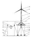
- the foundation consists of a horizontal hexagonal body built in concrete, or preferably in steel.
- the upper body is a hollow, buoyant body 7 containing an electrolyser for the production of oxygen and hydrogen. In the same hollow body are placed one or more tanks for the storage of the oxygen produced by electrolysis.
- This hollow body is also the support base a tower 10, to which a working platform 9 above the sea level is attached, which allows access to the inside of the tower 10.
- a nacelle On top of the tower 10 a nacelle is positioned containing the turbine and its accessories 12; the nacelle contains the rotor, the revolutions multiplier and the generator 11. All these items rest, without interruption, on the foundation 6, whose main purpose is therefore to provide a support base for the turbine and the electrolyser.
- the lower body consists first of a hollow body 4, cylindrical or polygonal, full or filled with ballast; this body acts as a counterweight to stabilize foundation movements.
- a second hollow body 13 preferably of spherical shape (or polygonal or cylindrical), to be used - also, if needed, with the hollow body 7 of the foundation 6 - as a reservoir for the storage of the hydrogen produced by the electrolyser.
- the entire structure is designed to stand against external natural forces (wind, waves, currents, tides) through the joint and combined action of two forces: the force, based on Archimedes principle, which pushes the structure upwards vertically, and the reaction produced by the anchoring chains 3a, which pulls the structure downwards; these two forces, however, are not sufficient to ensure the absolute stability of the foundation 6, necessary for the correct working of the turbine.
- the entire structure is attached with cables or preferably by chains 3a, 3b to bottom-weights 2, placed on the sea floor 1.
- chains 3a, 3b To the outside rim of the foundation 6 are attached the main vertical chains 3a that tie the foundation 6 to the bottom-weights 2 at the bottom of the sea (sea floor 1).
- From the central ballast 4 go off additional chains 3b placed diagonally, also attached to the bottom-weights 2, whose function is to off-set and prevent any horizontal shifting of the structure.
- the installation is no longer positioned above the foundation 6 but on its side. More precisely, from each main bottom-weight 2 placed on the sea floor 1 go off some anchoring ropes 18, which connect the bottom-weight 2 to floats 15 which are themselves connected through additional anchoring ropes 18 to other bottom- weights 19 on the sea floor. From the floats 15 go off ropes 16 which connect the floats 15 to the fish farming installation, which consists of a cage 17 on top of which is placed the dispenser 14 used to provide fish-food inside the cage 17.
- the method of construction of the submerged foundation 6 is totally innovative, as it creates a stable structure able to withstand and compensate automatically the impact of all natural forces acting at the site where the foundation is located (winds, waves, marine currents, tides of any foreseeable intensity).
- using the structure to house a facility to produce and stock hydrogen and oxygen is very innovative. Furthermore it is possible to use the produced and stored oxygen to oxygenize the water in the fish farming facility and to produce electrical energy using fuel cells placed inside the hollow body 7 above the foundation 6, which recombining oxygen and hydrogen previously created by electrolysis can produce electricity.
- the innovative content of the fish farming facility comprises various elements.
- the fact that the facility uses the submerged floating foundation 6 as its primary anchoring support provides greater stability and allows the breeding of any fish species in open and deep waters.
- the described facility is completely automatic with regard to the feeding of the fish and the oxygenation of the water.
- Such a combined facility allows the use of a single structure to generate at least three revenue streams from: the turbine (electricity), the electrolyser (hydrogen) and the aquaculture plant (sea food). Also innovative is the fact that a limited amount of space is used to generate substantial financial benefits, while totally respecting the environment.
Abstract
Description
- The present invention relates to the combination of innovative techniques for the construction of a submerged floating foundation, to be used as a submerged support base for a wind turbine and for an electrolyser, and with the possibility of utilising the entire submerged facility to house additional equipment; the entire structure to be combined with fish farming facilities, placed in the immediate vicinity of the foundation and attached permanently to the foundation with various cables or ropes.
-
WO 2004/05572 A2 US 6 027 286 A . - The innovative content does not only relate to the creation, at a depth below the area affected by wave movements, in fresh or sea waters, of a submerged floating foundation, by itself a technical innovation in view of the method used for executing the work, but also to the use of the structure to house an electrolyser for the electrolysis of water and the production and storage of hydrogen, together with all the equipment required to carry out these activities. A second innovation relates to the particular method used to make the structure rigid through the use of chains and pipes, and to the particular method used to stabilize the foundation by using bottom-weights. Furthermore, the particular method of anchoring the structure to the sea floor permits the positioning and the realization of a fish farming facility.
- The invention comprises the following elements, described and evidenced in the attached drawings.
- The foundation consists of a horizontal hexagonal body built in concrete, or preferably in steel.
- At the centre of the foundation are attached two bodies, one on the upper side, pointing towards the
sea surface 8 and one on the lower side, pointing towards the ocean floor 1. - The upper body is a hollow,
buoyant body 7 containing an electrolyser for the production of oxygen and hydrogen. In the same hollow body are placed one or more tanks for the storage of the oxygen produced by electrolysis. This hollow body is also the support base atower 10, to which a working platform 9 above the sea level is attached, which allows access to the inside of thetower 10. - On top of the tower 10 a nacelle is positioned containing the turbine and its
accessories 12; the nacelle contains the rotor, the revolutions multiplier and thegenerator 11. All these items rest, without interruption, on thefoundation 6, whose main purpose is therefore to provide a support base for the turbine and the electrolyser. - The lower body consists first of a
hollow body 4, cylindrical or polygonal, full or filled with ballast; this body acts as a counterweight to stabilize foundation movements. To thisfirst body 4 is permanently attached a secondhollow body 13, preferably of spherical shape (or polygonal or cylindrical), to be used - also, if needed, with thehollow body 7 of the foundation 6 - as a reservoir for the storage of the hydrogen produced by the electrolyser. - Inside the structure run the cables for the transmission of electricity from the nacelle and the pipes for the transport of hydrogen from the electrolyser to the storage containers; from the main body go off the cables and the pipes for the transmission of the electricity, hydrogen and oxygen produced either directly to shore or towards intermediate structures, such as ships or other storage and transport facilities.
- The entire structure is designed to stand against external natural forces (wind, waves, currents, tides) through the joint and combined action of two forces: the force, based on Archimedes principle, which pushes the structure upwards vertically, and the reaction produced by the
anchoring chains 3a, which pulls the structure downwards; these two forces, however, are not sufficient to ensure the absolute stability of thefoundation 6, necessary for the correct working of the turbine. - In order to make the structure more rigid and better able to resist horizontal external forces (and to prevent capsizing), in addition to positioning the central ballast below the
foundation 6, further precautions have been added. These are shown in the drawing as rigid metal pipes 6 (although reinforced cement is also possible), placed above thefoundation 6 and fastened to the top of the upper buoyanthollow body 7. It is possible that thesepipes 5 will be replaced by chains attached on the upper part in the same manner as thepipes 5, or also attached to the lowerhollow body 4 below thefoundation 6 and also to thehydrogen reservoirs 13. - The entire structure is attached with cables or preferably by
chains weights 2, placed on the sea floor 1. To the outside rim of thefoundation 6 are attached the mainvertical chains 3a that tie thefoundation 6 to the bottom-weights 2 at the bottom of the sea (sea floor 1). From thecentral ballast 4 go offadditional chains 3b placed diagonally, also attached to the bottom-weights 2, whose function is to off-set and prevent any horizontal shifting of the structure. - Further innovation is represented by the new positioning system for the fish farming installation. The installation is no longer positioned above the
foundation 6 but on its side. More precisely, from each main bottom-weight 2 placed on the sea floor 1 go off someanchoring ropes 18, which connect the bottom-weight 2 tofloats 15 which are themselves connected throughadditional anchoring ropes 18 to other bottom-weights 19 on the sea floor. From thefloats 15 go offropes 16 which connect thefloats 15 to the fish farming installation, which consists of acage 17 on top of which is placed thedispenser 14 used to provide fish-food inside thecage 17. - The scope for the use of this technology is almost unlimited. In fact, in addition to its application to the production of electricity, of hydrogen and of oxygen, it includes aquaculture. Furthermore, thanks to the characteristics of the
foundation 6 and of the structure resting on it, it can be used as a meteorological station, as a substation, or as a facility for the storage of energy, hydrogen and oxygen and more generally for other activities in the open sea. - Existing technologies do not foresee such combination of inventions, which are anyway innovative in their own right.
- As a matter of fact, the method of construction of the submerged
foundation 6 is totally innovative, as it creates a stable structure able to withstand and compensate automatically the impact of all natural forces acting at the site where the foundation is located (winds, waves, marine currents, tides of any foreseeable intensity). - In addition, using the structure to house a facility to produce and stock hydrogen and oxygen is very innovative. Furthermore it is possible to use the produced and stored oxygen to oxygenize the water in the fish farming facility and to produce electrical energy using fuel cells placed inside the
hollow body 7 above thefoundation 6, which recombining oxygen and hydrogen previously created by electrolysis can produce electricity. - The Innovative content of the fish farming facility comprises various elements.
- Firstly, the method of construction is greatly changed by the current invention.
- Secondly, the fact that the facility uses the submerged
floating foundation 6 as its primary anchoring support provides greater stability and allows the breeding of any fish species in open and deep waters. - Thirdly, the described facility is completely automatic with regard to the feeding of the fish and the oxygenation of the water.
- The main technical aspects of this innovative construction, although combined to create a single structure, each reflect innovative and autonomous methodologies in their own right, which, if used in combination among them result in the creation of a single facility, with economic advantages and lower costs.
- Such a combined facility allows the use of a single structure to generate at least three revenue streams from: the turbine (electricity), the electrolyser (hydrogen) and the aquaculture plant (sea food). Also innovative is the fact that a limited amount of space is used to generate substantial financial benefits, while totally respecting the environment.
- Various phases in the implementation of the project may be carried out at different times and be subject to changes and modifications, to take account of the geography of the site.
Claims (20)
- A method of installing a submerged floating foundation (6) as a support base for the installation of a wind turbine and an electrolyser for electrolysis of water, the foundation (6) having an upper side and a lower side, wherein chains (3a, 3b) or pipes (5) are positioned both on the upper and lower sides of the foundation (6), in order to make more rigid and stable the submerged floating foundation (6) with blocked vertical thrust, characterized In that a hollow body (7) is attached on the upper side of the foundation (6) and another hollow body (4) as a first one on the lower side of the foundation (6) whereby the hollow body (7) attached to the upper side of the foundation (6) is used as a support base for a tower (10) on top of which a nacelle containing the wind turbine is positioned and whereby a hollow body (7, 13) is used for the storage of hydrogen and/or oxygen produced by the electrolyzer.
- A method according to claim 1, characterized in that the electrolyser is arranged in the hollow body (7) on the upper side of the foundation (6).
- A method according to claim 1 or 2, characterized In that one or more tanks for the storage of oxygen produced by the electrolyser by electrolysis are provided in the hollow body (7) on the upper side of the foundation.
- A method according to one of claims 1 to 3 wherein the submerged floating foundation (6) with blocked vertical thrust, to bottom-weights (2) placed on a sea floor (1) using steel chains (3a, 3b) placed diagonally and/or vertically to neutralize possible horizontal shifts and therefore provides additional stability.
- A method according to one of claims 1 to 4 wherein the first one hollow body (4) on the lower side of the foundation (6) is full or filled with ballast and used as a counter-weight and placed below the submerged floating foundation (6) with blocked vertical thrust, thus moving the centre of gravity of the whole structure below its centre of rotation, thus avoiding and neutralizing possible external forces which may otherwise cause rotation and tipping over of the structure.
- A method according to one of claims 1 to 5 wherein a cylinder or floating tank is installed and positioned above the submerged foundation (6) and fastened to the foundation (6).
- A method according to claim 6 wherein the floating tank is used as a container for the electrolyser.
- A method according to one of claims 1 to 7 wherein a second hollow body (13) is attached and fastened on the lower side of the first one hollow body (4) provided on the lower side of the foundation (6) whereby the second hollow body (13) is used as a reservoir for storage of the hydrogen produced by the electrolyser.
- A method according to one of claims 1 to 8 wherein the foundation (6).is anchored by attachment to the bottom weights (2) using steel cables or chains (3a) attached to an outside rim of the foundation (6) and extending vertically to the bottom weights (2) and chains (3b) extending diagonally from the first hollow body (4) on the lower side of the foundation (6) used as a counter-weight to the bottom weights (2) at the sea floor (1) wherein the bottom weights (2) are buried in the sand below the sea floor (1), and filled with rubble and sand.
- A method according to one of claims 1 to 9, characterized in that a facility for fish farming, made of cages (17) for the breeding of various types of fish, is additionally provided to the floating foundation (6) which is fixed with ropes (16, 18) or chains to floats (15) on the sea surface (8).
- A method according to claim 10 wherein the floats (15) are anchored with ropes (18) or chains to bottom-weights (2, 19) on the sea floor (1).
- A method according to claim 10 or 11 wherein the floats (15) are connected to the bottom-weights (2, 19) holding the submerged floating foundation (6) in place, so as to create a single multi-purpose installation, entirely or partially submerged.
- A device to carry out the methods according to one of the preceding claims, comprising a submerged floating foundation (6) which is anchored with blocked vertical thrust to bottom-weights (2) placed on the sea floor (1) by vertically and/or diagonally placed chains (3a, 3b), which floating foundation (6) is used as a support base for a tower (10) holding a wind turbine with a facility for the production of hydrogen placed above the foundation (6) and a facility for storage of hydrogen inside or below the foundation (6), the foundation (6) having an upper side and a lower side, characterized in that a hollow body (7) is attached on the upper side of the foundation (6) and another hollow body (4) as a first one is attached on the lower side of the foundation (6) whereby the hollow body (7) attached to the upper side is used as a support base for the tower (10) wherein the floating foundation (6) is provided with an electrolyser for electrolysis of water and production of hydrogen, whereby a hollow body (7, 13) is used for the storage of hydrogen and/or oxygen produced by the electrolyser..
- A device according to claim 13, characterized in that the electrolyser is arranged in the hollow body (7) on the upper side of the foundation (6).
- A device according to claim 13, characterized in that one or more tanks for the storage of oxygen produced by the electrolyser by electrolysis are provided in the hollow body (7) on the upper side of the foundation (6).
- A device according to one of the claims 13 to 15, characterised in that a cylinder or floating tank provided for hydrogen storage is located above the submerged foundation (6) and fastened to the foundation (6).
- A device according to one of the claims 13 to 16, characterised in that the first hollow body (4) on the lower side of the foundation (6) is full or filled with ballast and used as counter-weights and located below the submerged floating foundation (6) with blocked vertical thrust, thus moving the centre of gravity and of structures attached thereto below its centre of rotation.
- A device according to claim 17 characterised in that a second hollow body (13) is attached and fastened to the lower side of the first one hollow body (4) provided on the lower side of the foundation (6) whereby the second hollow body (13) is used as a reservoir for storage of the hydrogen produced by the electrolyser.
- A device according to one of the preceding claims 13 to 18, characterised in that suitable cables or chains (3a, 3b) connecting vertically and/or diagonally the foundation (6) to bottom-weights (19) buried in the sand below the sea floor (1), and filled with gravel and/or sand.
- A device according to one of the preceding claims 13 to 19, characterised in that a facility for fish farming, made of cages (17) for the breeding of various types of fish, is fixed with ropes (18) or chains to floats (15) on the sea surface (8) and to the bottom weights (2, 19) on the sea floor (1).
Applications Claiming Priority (2)
| Application Number | Priority Date | Filing Date | Title |
|---|---|---|---|
| IT000027U ITBA20040027U1 (en) | 2004-10-06 | 2004-10-06 | (METHOD OF) CONSTRUCTION OF A SUBMERGED PLATFORM WITH A THRUST BLOCKED TO BE USED AS A SUPPORT FOR THE INSTALLATION OF AIRCONDITIONER, OF ELECTROLISER FOR THE ELECTROLYSIS OF WATER AND OF OTHER PLANTS AND / OR MACHINERY, COMBINED WITH ACTIVITY |
| PCT/IB2005/002950 WO2006038091A2 (en) | 2004-10-06 | 2005-10-04 | Construction of a submerged floating foundation |
Publications (2)
| Publication Number | Publication Date |
|---|---|
| EP1809818A2 EP1809818A2 (en) | 2007-07-25 |
| EP1809818B1 true EP1809818B1 (en) | 2011-12-14 |
Family
ID=35997250
Family Applications (1)
| Application Number | Title | Priority Date | Filing Date |
|---|---|---|---|
| EP05790678A Not-in-force EP1809818B1 (en) | 2004-10-06 | 2005-10-04 | Construction of a submerged floating foundation |
Country Status (9)
| Country | Link |
|---|---|
| US (2) | US20080089746A1 (en) |
| EP (1) | EP1809818B1 (en) |
| JP (1) | JP4814246B2 (en) |
| CN (1) | CN101076634B (en) |
| AT (1) | ATE537302T1 (en) |
| CA (1) | CA2583296A1 (en) |
| ES (1) | ES2378549T3 (en) |
| IT (1) | ITBA20040027U1 (en) |
| WO (1) | WO2006038091A2 (en) |
Families Citing this family (45)
| Publication number | Priority date | Publication date | Assignee | Title |
|---|---|---|---|---|
| ITBA20040027U1 (en) | 2004-10-06 | 2005-01-06 | Enertec Ag | (METHOD OF) CONSTRUCTION OF A SUBMERGED PLATFORM WITH A THRUST BLOCKED TO BE USED AS A SUPPORT FOR THE INSTALLATION OF AIRCONDITIONER, OF ELECTROLISER FOR THE ELECTROLYSIS OF WATER AND OF OTHER PLANTS AND / OR MACHINERY, COMBINED WITH ACTIVITY |
| CA2699380A1 (en) * | 2007-09-13 | 2009-03-19 | Floating Windfarms Corporation | Offshore vertical-axis wind turbine and associated systems and methods |
| ITTO20070666A1 (en) * | 2007-09-24 | 2009-03-25 | Blue H Intellectual Properties | OFFSHORE WIND POWER CONVERSION SYSTEM FOR DEEP WATER |
| EP2048759A1 (en) * | 2007-10-09 | 2009-04-15 | EM Microelectronic-Marin SA | Facility for producing and storing renewable energy |
| ES2301443B1 (en) * | 2007-11-15 | 2009-08-25 | Acciona Energia, S.A. | WATER RESOURCES MEASUREMENT SYSTEM AT SEA, ENERGY PRODUCER AND INSTALLATION METHOD. |
| DE102008003647B4 (en) | 2008-01-09 | 2011-12-15 | Gicon Windpower Ip Gmbh | Floating foundation structure with buoyancy components, in dissolved construction |
| CN101566130B (en) * | 2008-04-23 | 2010-12-22 | 中国科学院工程热物理研究所 | Anti-tilting suspended wind turbine unit |
| EP2143629B1 (en) * | 2008-07-08 | 2013-04-24 | Siemens Aktiengesellschaft | Arrangement for stabilization of a floating foundation |
| CA2747541C (en) | 2008-12-18 | 2017-07-11 | Single Buoy Moorings Inc. | Removable offshore wind turbines with pre-installed mooring system |
| DE102009044278A1 (en) * | 2009-10-16 | 2011-04-21 | JÄHNIG, Jens | Floating foundation with improved bracing |
| DE102009058278B3 (en) * | 2009-12-13 | 2011-05-19 | Stiftung Alfred-Wegener-Institut Für Polar- Und Meeresforschung | Device for locating and harvesting marine hard-bottomed animals |
| DK201000008A (en) * | 2010-01-07 | 2010-12-18 | Vestas Wind Sys As | Method of erecting a floating off-shore wind turbine and a floating off-shore wind turbine |
| CN102235011A (en) * | 2010-04-27 | 2011-11-09 | 南通大学 | Flexible floating foundation for offshore wind generating sets |
| CA2740737A1 (en) | 2010-05-20 | 2011-11-20 | Nordest Marine Inc. | Stream flow hydroelectric generator system, and method of handling same |
| US20120103244A1 (en) * | 2010-10-28 | 2012-05-03 | Jin Wang | Truss Cable Semi-submersible Floater for Offshore Wind Turbines and Construction Methods |
| KR101024386B1 (en) * | 2011-01-20 | 2011-03-23 | 엔엔티시스템즈(주) | Automatic feeding system for underwater fish cages |
| US8662793B2 (en) * | 2011-05-20 | 2014-03-04 | Carlos Wong | Floating wind farm with energy storage facility |
| KR101337646B1 (en) * | 2011-07-08 | 2013-12-05 | 삼성중공업 주식회사 | Offshore wind turbine generator, lifting zig for transporting offshore wind turbine generator, system and method for installing offshore wind turbine generator using the same |
| CN102433890B (en) * | 2011-12-22 | 2014-12-24 | 新疆金风科技股份有限公司 | Floating type offshore wind turbine base and positioning system thereof |
| WO2013135291A1 (en) | 2012-03-15 | 2013-09-19 | Ocean Electric Inc. | An offshore floating wind turbine for electric power generation |
| DE102012007613A1 (en) | 2012-04-16 | 2013-10-17 | Walter Schopf | Star-shaped swimming support base for offshore wind energy plant, has control unit that controls operation cycle of wind power machine such that configurations of hardware and software are introduced at wind power machine |
| ES2454044B1 (en) * | 2012-10-08 | 2015-03-10 | Iberdrola Ingenieria Y Construccion S A U | Floating platform in tension of special application for wind use |
| NL2009763C2 (en) * | 2012-11-06 | 2014-05-08 | Mecal Wind Turbine Design B V | Floatable transportation and installation structure for transportation and installation of a floating wind turbine, a floating wind turbine and method for transportation and installation of the same. |
| EP2821335B1 (en) * | 2013-07-02 | 2018-11-14 | Alstom Renovables España, S.L. | Floating wind turbine |
| EP3049668B1 (en) | 2013-09-24 | 2019-02-27 | University of Maine System Board of Trustees | Floating wind turbine support system |
| ES2555500B1 (en) * | 2014-05-27 | 2016-12-13 | Sea Wind Towers Sl | Floating work and installation procedure |
| US9725870B2 (en) | 2014-12-09 | 2017-08-08 | Sofec, Inc. | Apparatus and method of using a disconnectable floating spar buoy jacket wind turbine |
| CN104743080A (en) * | 2015-04-06 | 2015-07-01 | 陈佳宇 | Floating unit and waterborne pipeline supporting system consisting of same |
| CN104802949A (en) * | 2015-04-06 | 2015-07-29 | 陈佳宇 | Float unit and combined water platform |
| NO341974B1 (en) * | 2015-08-12 | 2018-03-05 | Hauge Aqua As | Floating and submersible closed-contained aquaculture farming invention |
| CN106043609A (en) * | 2016-06-16 | 2016-10-26 | 江苏海上龙源风力发电有限公司 | Movable floating type offshore anemometer tower |
| DE102016118079B3 (en) * | 2016-09-26 | 2017-09-28 | Aerodyn Engineering Gmbh | Mooring buoy for a floating wind turbine |
| NL2017797B1 (en) * | 2016-11-16 | 2018-05-25 | Seanovations Ipa B V | Offshore system for converting energy, and method for the assembly and use of such an offshore system |
| US10975541B2 (en) | 2017-09-05 | 2021-04-13 | Sofec, Inc. | Offshore structure mating system and installation method |
| US10716296B2 (en) * | 2017-11-15 | 2020-07-21 | Graduate School At Shenzhen, Tsinghua University | Floating offshore wind turbine integrated with steel fish farming cage |
| US11472519B2 (en) | 2018-01-30 | 2022-10-18 | Alliance For Sustainable Energy, Llc | Flexible aquatic substructures |
| CN108252263A (en) * | 2018-03-06 | 2018-07-06 | 大连理工大学 | A kind of anti-wave of floating for deep-sea breeding carries and wind energy integrated system |
| US20200022341A1 (en) * | 2018-07-23 | 2020-01-23 | Powerchina Huadong Engineering Corporation Limited | Combined structure of a fishing net cage and floating wind turbine foundation and construction method for same |
| EP3760860A1 (en) * | 2019-07-05 | 2021-01-06 | Siemens Gamesa Renewable Energy A/S | Energy generation and energy storage in a wind turbine structure |
| NL2024072B1 (en) * | 2019-10-21 | 2021-06-22 | Itrec Bv | A method for operating a vessel and a floating wind turbine and a combination of vessel and floating wind turbine. |
| FR3108953B1 (en) | 2020-04-06 | 2023-07-21 | Olivier Juin | SUPPORTING STRUCTURE FOR THE INSTALLATION OF WIND ENERGY CAPTURE MODULES |
| CN112177421A (en) * | 2020-09-21 | 2021-01-05 | 吴峰 | Signal transmission tower column foot fixing device based on 5G |
| US20220400636A1 (en) * | 2021-06-16 | 2022-12-22 | Taerra Systems, Inc. | Kelp growth apparatus and method for kelp harvesting |
| US20220400656A1 (en) * | 2021-06-22 | 2022-12-22 | John Ferguson | Coral Reef Float |
| CN113417313B (en) * | 2021-07-20 | 2023-02-03 | 四川电力设计咨询有限责任公司 | Section steel support shroud plate assembled foundation for frozen soil area |
Family Cites Families (44)
| Publication number | Priority date | Publication date | Assignee | Title |
|---|---|---|---|---|
| US2394764A (en) * | 1944-03-16 | 1946-02-12 | Carnegie Illinois Steel Corp | Metal pontoon |
| GB849887A (en) | 1958-06-25 | 1960-09-28 | California Research Corp | Anchoring systems |
| US4645379A (en) * | 1981-01-29 | 1987-02-24 | Conoco Inc. | Pyramidal offshore structure |
| NL8403978A (en) * | 1984-12-31 | 1986-07-16 | Single Buoy Moorings | Mooring device. |
| US4764313A (en) * | 1986-11-03 | 1988-08-16 | Sunset Solar Systems Ltd. | Air driven water circulation mill |
| JPH0824509B2 (en) | 1991-05-30 | 1996-03-13 | 海洋科学技術センター | Submerged floating offshore structure |
| US5412903A (en) * | 1994-02-17 | 1995-05-09 | Mefalim Ymiem Vashkoht Ltd. | Sea cage fish farming system |
| US5617813A (en) * | 1995-03-31 | 1997-04-08 | Ocean Spar Technologies, Llc | Anchorable mobile spar and ring fish pen |
| US6164872A (en) * | 1996-09-27 | 2000-12-26 | Mitsubishi Heavy Industries, Ltd. | Method of production of large tank, system using such large tank and submerged tunneling method using the tank |
| US5873678A (en) * | 1996-12-23 | 1999-02-23 | Continental Emsco Company | Tension adjustment mechanism employing stepped or serrated ramps for adjusting tension of a tendon from a floating marine platform |
| US6027286A (en) * | 1997-06-19 | 2000-02-22 | Imodco, Inc. | Offshore spar production system and method for creating a controlled tilt of the caisson axis |
| US5961251A (en) * | 1997-12-29 | 1999-10-05 | Prendergast; Francis G. | Artificial seaweed device |
| KR100365095B1 (en) * | 1999-05-15 | 2002-12-18 | 신완철 | An apparatus for producing seawater gas and flammable gas products obtained by using the same |
| CN2377833Y (en) * | 1999-06-18 | 2000-05-17 | 海南瑞发东方海洋产业有限公司 | Deep-sea submersible net cage |
| JP2001165032A (en) | 1999-12-07 | 2001-06-19 | Mitsubishi Heavy Ind Ltd | Wind power generation device |
| US6554534B1 (en) * | 1999-12-29 | 2003-04-29 | Donal Butterfield | Flexible structure and method for controlling the quality of liquids |
| JP3518856B2 (en) * | 2000-03-06 | 2004-04-12 | 鹿島建設株式会社 | Wind power generator |
| ATE376623T1 (en) | 2000-03-28 | 2007-11-15 | Per Lauritsen | FLOATING OFFSHORE WIND TURBINE |
| DE10034847A1 (en) * | 2000-07-18 | 2002-02-14 | Maierform Maritime Technology | Fixed positioning of functional units on or in the water |
| WO2002010589A1 (en) | 2000-07-27 | 2002-02-07 | Christoffer Hannevig | Floating structure for mounting a wind turbine offshore |
| US6481378B1 (en) * | 2000-09-11 | 2002-11-19 | Fishfarm Tech Ltd. | Fish farming system and method |
| JP2002285952A (en) | 2001-03-23 | 2002-10-03 | Hitachi Zosen Corp | Floating type foundation structure for marine wind power generation |
| JP2002285951A (en) | 2001-03-23 | 2002-10-03 | Hitachi Zosen Corp | Floating type foundation structure for marine wind power generation |
| JP2002303454A (en) | 2001-03-30 | 2002-10-18 | Mitsubishi Heavy Ind Ltd | Floater type hydrogen and oxygen production system |
| FR2827015B1 (en) * | 2001-07-06 | 2005-12-23 | Bouygues Offshore | OFFSHORE WIND TURBINE AND METHOD OF CONSTRUCTION |
| GB0119969D0 (en) * | 2001-08-16 | 2001-10-10 | Ocean Technologies Ltd | Floating offshore windtower |
| DK1288122T3 (en) | 2001-08-30 | 2010-09-06 | Rund Stahl Bau Gmbh & Co | Floating foundation for a building project that protrudes above the surface of the water |
| DE10229390A1 (en) * | 2001-09-25 | 2003-04-24 | Thomas Nikolaus | Wind power machine has wind-powered rotor element driving hydraulic pumps either directly or indirectly, e.g. connected to rotor by regulator depending on rotor element power |
| CN2525798Y (en) * | 2001-10-31 | 2002-12-18 | 富阳市飞鹰船艇有限公司 | Stormy waves resisting deep water net box |
| DE50300043D1 (en) * | 2002-02-14 | 2004-09-09 | Rund Stahl Bau Gmbh & Co | Method for lowering a floating body of a floating foundation |
| JP2003252288A (en) * | 2002-02-27 | 2003-09-10 | Hitachi Zosen Corp | Floating body type base structure for marine wind power generation |
| DE60328971D1 (en) * | 2002-03-08 | 2009-10-08 | Ocean Wind Energy Systems | OFFSHORE WIND POWER PLANT |
| FR2837535A1 (en) | 2002-03-22 | 2003-09-26 | Doris Engineering | Sea based wind generator electricity installation having wind generator horizontal triangular floater placed three taut sections connected marine base part sea floor. |
| DE10219062A1 (en) | 2002-04-29 | 2003-11-13 | Walter Schopf | Facility for offshore wind energy for the open sea has tower with rotating gondola and a storage base for wind turbine having hub and rotor blades to drive generator |
| DK1509695T3 (en) | 2002-05-16 | 2008-11-10 | Mlh Global Corp Inc | Wind turbine with hydraulic transmission |
| NO320938B1 (en) * | 2002-08-13 | 2006-02-13 | Hammerfest Strom As | Device for founding an installation on a seabed as well as a method for installing the device |
| DE10241636A1 (en) | 2002-09-09 | 2004-03-25 | Horst Janietz | Wind power system has hydraulic gearbox, control parts that stationary on ground or mobile in watertight housing, wind vane rotor in gondola that drives hydraulic pump mounted behind it |
| ITBA20020047A1 (en) * | 2002-12-17 | 2004-06-18 | Enertec Aktiegesellschaft Ag | METHOD OF REALIZATION OF A SUBMERSIBLE PUSH-PLATFORM LOCKED FOR THE PRODUCTION OF ELECTRICITY FROM THE WIND IN THE OPEN SEA AND OF MARICULTURE PRODUCTS |
| JP4377337B2 (en) * | 2003-01-06 | 2009-12-02 | ベスタス ウィンド システムズ アクティーゼルスカブ | Wind turbine with floating base |
| CN2633018Y (en) * | 2003-07-11 | 2004-08-18 | 中国海洋大学 | Hoist lifting cultivating in net pen device |
| US9003631B2 (en) * | 2003-10-23 | 2015-04-14 | Shigeyuki Yamamoto | Power generation assemblies and apparatus |
| ITBA20040027U1 (en) * | 2004-10-06 | 2005-01-06 | Enertec Ag | (METHOD OF) CONSTRUCTION OF A SUBMERGED PLATFORM WITH A THRUST BLOCKED TO BE USED AS A SUPPORT FOR THE INSTALLATION OF AIRCONDITIONER, OF ELECTROLISER FOR THE ELECTROLYSIS OF WATER AND OF OTHER PLANTS AND / OR MACHINERY, COMBINED WITH ACTIVITY |
| US20060082160A1 (en) * | 2004-10-14 | 2006-04-20 | Lee Tommy L | Wind powered generator platform |
| ITTO20070666A1 (en) * | 2007-09-24 | 2009-03-25 | Blue H Intellectual Properties | OFFSHORE WIND POWER CONVERSION SYSTEM FOR DEEP WATER |
-
2004
- 2004-10-06 IT IT000027U patent/ITBA20040027U1/en unknown
-
2005
- 2005-10-04 EP EP05790678A patent/EP1809818B1/en not_active Not-in-force
- 2005-10-04 US US11/576,825 patent/US20080089746A1/en not_active Abandoned
- 2005-10-04 JP JP2007535262A patent/JP4814246B2/en not_active Expired - Fee Related
- 2005-10-04 AT AT05790678T patent/ATE537302T1/en active
- 2005-10-04 CA CA002583296A patent/CA2583296A1/en not_active Abandoned
- 2005-10-04 WO PCT/IB2005/002950 patent/WO2006038091A2/en active Application Filing
- 2005-10-04 CN CN2005800342436A patent/CN101076634B/en not_active Expired - Fee Related
- 2005-10-04 ES ES05790678T patent/ES2378549T3/en active Active
-
2010
- 2010-02-11 US US12/703,827 patent/US8235629B2/en not_active Expired - Fee Related
Also Published As
| Publication number | Publication date |
|---|---|
| ATE537302T1 (en) | 2011-12-15 |
| US8235629B2 (en) | 2012-08-07 |
| ES2378549T3 (en) | 2012-04-13 |
| CA2583296A1 (en) | 2006-04-13 |
| ITBA20040027U1 (en) | 2005-01-06 |
| CN101076634A (en) | 2007-11-21 |
| US20100150664A1 (en) | 2010-06-17 |
| EP1809818A2 (en) | 2007-07-25 |
| US20080089746A1 (en) | 2008-04-17 |
| WO2006038091A2 (en) | 2006-04-13 |
| JP4814246B2 (en) | 2011-11-16 |
| WO2006038091A3 (en) | 2006-06-22 |
| CN101076634B (en) | 2011-03-23 |
| JP2008516113A (en) | 2008-05-15 |
Similar Documents
| Publication | Publication Date | Title |
|---|---|---|
| EP1809818B1 (en) | Construction of a submerged floating foundation | |
| US7476074B2 (en) | Method for realising a submerged floating foundation with blocked vertical thrust for the coordinated production of mariculture and electrical energy using wind in open sea conditions and submergeable floating foundation for carrying loads to be used in said method | |
| US10774813B2 (en) | Floating structure and method of installing same | |
| RU2555778C2 (en) | Floating power generation station | |
| EP2993270B1 (en) | Submersible structure for actively supporting towers of generators and sub-stations or similar elements, in maritime facilities | |
| EP2604501B1 (en) | System of anchoring and mooring of floating wind turbine towers and corresponding methods for towing and erecting thereof | |
| US20120014752A1 (en) | Submersible Platform With Blocked Thrust For Offshore Wind Plants In Open Sea In Concrete-Steel Hybrid Solution | |
| CN108248783B (en) | construction method of offshore wind power submersible floating foundation | |
| JP2019069779A (en) | Ocean thermal energy conversion system loaded on vessel | |
| CN102506012A (en) | Semi-submersible anchoring type offshore wind generating set with integrated pedestal | |
| SG181578A1 (en) | Multi-purpose offshore platform and method for manufacturing and installing thereof | |
| KR102632315B1 (en) | Buoys and installation methods for them | |
| WO2017118998A1 (en) | Floating solar platform | |
| US20180119675A1 (en) | Gravity foundation for the installation of offshore wind turbines | |
| CN110745216A (en) | Fishery net cage and floating type fan foundation combined structure and construction method | |
| CN101400568A (en) | Mooring system | |
| CN208102275U (en) | It is a kind of can transportation by driving offshore wind farm buoyant foundation | |
| WO2011058595A2 (en) | Floating platform for panels | |
| NL2031193B1 (en) | Marine structure and method | |
| Li et al. | Offshore wind turbines and their installation | |
| GB2596097A (en) | Energy harnessing system and method of use thereof | |
| Aubault et al. | Offshore wind energy |
Legal Events
| Date | Code | Title | Description |
|---|---|---|---|
| PUAI | Public reference made under article 153(3) epc to a published international application that has entered the european phase |
Free format text: ORIGINAL CODE: 0009012 |
|
| 17P | Request for examination filed |
Effective date: 20070507 |
|
| AK | Designated contracting states |
Kind code of ref document: A2 Designated state(s): AT BE BG CH CY CZ DE DK EE ES FI FR GB GR HU IE IS IT LI LT LU LV MC NL PL PT RO SE SI SK TR |
|
| DAX | Request for extension of the european patent (deleted) | ||
| 17Q | First examination report despatched |
Effective date: 20101116 |
|
| RAP1 | Party data changed (applicant data changed or rights of an application transferred) |
Owner name: BLUE H INTELLECTUAL PROPERTY CYPRUS LIMITED |
|
| GRAP | Despatch of communication of intention to grant a patent |
Free format text: ORIGINAL CODE: EPIDOSNIGR1 |
|
| GRAS | Grant fee paid |
Free format text: ORIGINAL CODE: EPIDOSNIGR3 |
|
| GRAA | (expected) grant |
Free format text: ORIGINAL CODE: 0009210 |
|
| AK | Designated contracting states |
Kind code of ref document: B1 Designated state(s): AT BE BG CH CY CZ DE DK EE ES FI FR GB GR HU IE IS IT LI LT LU LV MC NL PL PT RO SE SI SK TR |
|
| REG | Reference to a national code |
Ref country code: GB Ref legal event code: FG4D |
|
| REG | Reference to a national code |
Ref country code: CH Ref legal event code: EP |
|
| REG | Reference to a national code |
Ref country code: IE Ref legal event code: FG4D |
|
| REG | Reference to a national code |
Ref country code: DE Ref legal event code: R096 Ref document number: 602005031681 Country of ref document: DE Effective date: 20120223 |
|
| REG | Reference to a national code |
Ref country code: PT Ref legal event code: SC4A Free format text: AVAILABILITY OF NATIONAL TRANSLATION Effective date: 20120228 |
|
| REG | Reference to a national code |
Ref country code: NL Ref legal event code: VDEP Effective date: 20111214 |
|
| REG | Reference to a national code |
Ref country code: ES Ref legal event code: FG2A Ref document number: 2378549 Country of ref document: ES Kind code of ref document: T3 Effective date: 20120413 |
|
| PG25 | Lapsed in a contracting state [announced via postgrant information from national office to epo] |
Ref country code: LT Free format text: LAPSE BECAUSE OF FAILURE TO SUBMIT A TRANSLATION OF THE DESCRIPTION OR TO PAY THE FEE WITHIN THE PRESCRIBED TIME-LIMIT Effective date: 20111214 |
|
| LTIE | Lt: invalidation of european patent or patent extension |
Effective date: 20111214 |
|
| PG25 | Lapsed in a contracting state [announced via postgrant information from national office to epo] |
Ref country code: LV Free format text: LAPSE BECAUSE OF FAILURE TO SUBMIT A TRANSLATION OF THE DESCRIPTION OR TO PAY THE FEE WITHIN THE PRESCRIBED TIME-LIMIT Effective date: 20111214 Ref country code: NL Free format text: LAPSE BECAUSE OF FAILURE TO SUBMIT A TRANSLATION OF THE DESCRIPTION OR TO PAY THE FEE WITHIN THE PRESCRIBED TIME-LIMIT Effective date: 20111214 Ref country code: SI Free format text: LAPSE BECAUSE OF FAILURE TO SUBMIT A TRANSLATION OF THE DESCRIPTION OR TO PAY THE FEE WITHIN THE PRESCRIBED TIME-LIMIT Effective date: 20111214 Ref country code: SE Free format text: LAPSE BECAUSE OF FAILURE TO SUBMIT A TRANSLATION OF THE DESCRIPTION OR TO PAY THE FEE WITHIN THE PRESCRIBED TIME-LIMIT Effective date: 20111214 Ref country code: GR Free format text: LAPSE BECAUSE OF FAILURE TO SUBMIT A TRANSLATION OF THE DESCRIPTION OR TO PAY THE FEE WITHIN THE PRESCRIBED TIME-LIMIT Effective date: 20120315 |
|
| PG25 | Lapsed in a contracting state [announced via postgrant information from national office to epo] |
Ref country code: CY Free format text: LAPSE BECAUSE OF FAILURE TO SUBMIT A TRANSLATION OF THE DESCRIPTION OR TO PAY THE FEE WITHIN THE PRESCRIBED TIME-LIMIT Effective date: 20111214 Ref country code: BE Free format text: LAPSE BECAUSE OF FAILURE TO SUBMIT A TRANSLATION OF THE DESCRIPTION OR TO PAY THE FEE WITHIN THE PRESCRIBED TIME-LIMIT Effective date: 20111214 |
|
| PG25 | Lapsed in a contracting state [announced via postgrant information from national office to epo] |
Ref country code: EE Free format text: LAPSE BECAUSE OF FAILURE TO SUBMIT A TRANSLATION OF THE DESCRIPTION OR TO PAY THE FEE WITHIN THE PRESCRIBED TIME-LIMIT Effective date: 20111214 Ref country code: BG Free format text: LAPSE BECAUSE OF FAILURE TO SUBMIT A TRANSLATION OF THE DESCRIPTION OR TO PAY THE FEE WITHIN THE PRESCRIBED TIME-LIMIT Effective date: 20120314 Ref country code: CZ Free format text: LAPSE BECAUSE OF FAILURE TO SUBMIT A TRANSLATION OF THE DESCRIPTION OR TO PAY THE FEE WITHIN THE PRESCRIBED TIME-LIMIT Effective date: 20111214 Ref country code: SK Free format text: LAPSE BECAUSE OF FAILURE TO SUBMIT A TRANSLATION OF THE DESCRIPTION OR TO PAY THE FEE WITHIN THE PRESCRIBED TIME-LIMIT Effective date: 20111214 Ref country code: IS Free format text: LAPSE BECAUSE OF FAILURE TO SUBMIT A TRANSLATION OF THE DESCRIPTION OR TO PAY THE FEE WITHIN THE PRESCRIBED TIME-LIMIT Effective date: 20120414 |
|
| PG25 | Lapsed in a contracting state [announced via postgrant information from national office to epo] |
Ref country code: PL Free format text: LAPSE BECAUSE OF FAILURE TO SUBMIT A TRANSLATION OF THE DESCRIPTION OR TO PAY THE FEE WITHIN THE PRESCRIBED TIME-LIMIT Effective date: 20111214 Ref country code: RO Free format text: LAPSE BECAUSE OF FAILURE TO SUBMIT A TRANSLATION OF THE DESCRIPTION OR TO PAY THE FEE WITHIN THE PRESCRIBED TIME-LIMIT Effective date: 20111214 |
|
| REG | Reference to a national code |
Ref country code: AT Ref legal event code: MK05 Ref document number: 537302 Country of ref document: AT Kind code of ref document: T Effective date: 20111214 |
|
| PLBE | No opposition filed within time limit |
Free format text: ORIGINAL CODE: 0009261 |
|
| STAA | Information on the status of an ep patent application or granted ep patent |
Free format text: STATUS: NO OPPOSITION FILED WITHIN TIME LIMIT |
|
| PG25 | Lapsed in a contracting state [announced via postgrant information from national office to epo] |
Ref country code: DK Free format text: LAPSE BECAUSE OF FAILURE TO SUBMIT A TRANSLATION OF THE DESCRIPTION OR TO PAY THE FEE WITHIN THE PRESCRIBED TIME-LIMIT Effective date: 20111214 |
|
| 26N | No opposition filed |
Effective date: 20120917 |
|
| PG25 | Lapsed in a contracting state [announced via postgrant information from national office to epo] |
Ref country code: IT Free format text: LAPSE BECAUSE OF FAILURE TO SUBMIT A TRANSLATION OF THE DESCRIPTION OR TO PAY THE FEE WITHIN THE PRESCRIBED TIME-LIMIT Effective date: 20111214 |
|
| REG | Reference to a national code |
Ref country code: DE Ref legal event code: R097 Ref document number: 602005031681 Country of ref document: DE Effective date: 20120917 |
|
| PG25 | Lapsed in a contracting state [announced via postgrant information from national office to epo] |
Ref country code: AT Free format text: LAPSE BECAUSE OF FAILURE TO SUBMIT A TRANSLATION OF THE DESCRIPTION OR TO PAY THE FEE WITHIN THE PRESCRIBED TIME-LIMIT Effective date: 20111214 |
|
| PGFP | Annual fee paid to national office [announced via postgrant information from national office to epo] |
Ref country code: DE Payment date: 20121031 Year of fee payment: 8 Ref country code: PT Payment date: 20120228 Year of fee payment: 8 Ref country code: FR Payment date: 20121113 Year of fee payment: 8 |
|
| PGFP | Annual fee paid to national office [announced via postgrant information from national office to epo] |
Ref country code: ES Payment date: 20121017 Year of fee payment: 8 Ref country code: GB Payment date: 20121024 Year of fee payment: 8 |
|
| PG25 | Lapsed in a contracting state [announced via postgrant information from national office to epo] |
Ref country code: MC Free format text: LAPSE BECAUSE OF NON-PAYMENT OF DUE FEES Effective date: 20121031 |
|
| REG | Reference to a national code |
Ref country code: CH Ref legal event code: PL |
|
| PG25 | Lapsed in a contracting state [announced via postgrant information from national office to epo] |
Ref country code: FI Free format text: LAPSE BECAUSE OF FAILURE TO SUBMIT A TRANSLATION OF THE DESCRIPTION OR TO PAY THE FEE WITHIN THE PRESCRIBED TIME-LIMIT Effective date: 20111214 |
|
| REG | Reference to a national code |
Ref country code: IE Ref legal event code: MM4A |
|
| PG25 | Lapsed in a contracting state [announced via postgrant information from national office to epo] |
Ref country code: IE Free format text: LAPSE BECAUSE OF NON-PAYMENT OF DUE FEES Effective date: 20121004 Ref country code: LI Free format text: LAPSE BECAUSE OF NON-PAYMENT OF DUE FEES Effective date: 20121031 Ref country code: CH Free format text: LAPSE BECAUSE OF NON-PAYMENT OF DUE FEES Effective date: 20121031 |
|
| REG | Reference to a national code |
Ref country code: PT Ref legal event code: MM4A Free format text: LAPSE DUE TO NON-PAYMENT OF FEES Effective date: 20140404 |
|
| PG25 | Lapsed in a contracting state [announced via postgrant information from national office to epo] |
Ref country code: TR Free format text: LAPSE BECAUSE OF FAILURE TO SUBMIT A TRANSLATION OF THE DESCRIPTION OR TO PAY THE FEE WITHIN THE PRESCRIBED TIME-LIMIT Effective date: 20111214 |
|
| PG25 | Lapsed in a contracting state [announced via postgrant information from national office to epo] |
Ref country code: LU Free format text: LAPSE BECAUSE OF NON-PAYMENT OF DUE FEES Effective date: 20121004 |
|
| GBPC | Gb: european patent ceased through non-payment of renewal fee |
Effective date: 20131004 |
|
| PG25 | Lapsed in a contracting state [announced via postgrant information from national office to epo] |
Ref country code: GB Free format text: LAPSE BECAUSE OF NON-PAYMENT OF DUE FEES Effective date: 20131004 Ref country code: HU Free format text: LAPSE BECAUSE OF FAILURE TO SUBMIT A TRANSLATION OF THE DESCRIPTION OR TO PAY THE FEE WITHIN THE PRESCRIBED TIME-LIMIT Effective date: 20051004 |
|
| REG | Reference to a national code |
Ref country code: DE Ref legal event code: R119 Ref document number: 602005031681 Country of ref document: DE Effective date: 20140501 |
|
| REG | Reference to a national code |
Ref country code: FR Ref legal event code: ST Effective date: 20140630 |
|
| PG25 | Lapsed in a contracting state [announced via postgrant information from national office to epo] |
Ref country code: DE Free format text: LAPSE BECAUSE OF NON-PAYMENT OF DUE FEES Effective date: 20140501 Ref country code: PT Free format text: LAPSE BECAUSE OF NON-PAYMENT OF DUE FEES Effective date: 20140404 Ref country code: FR Free format text: LAPSE BECAUSE OF NON-PAYMENT OF DUE FEES Effective date: 20131031 |
|
| REG | Reference to a national code |
Ref country code: ES Ref legal event code: FD2A Effective date: 20141107 |
|
| PG25 | Lapsed in a contracting state [announced via postgrant information from national office to epo] |
Ref country code: ES Free format text: LAPSE BECAUSE OF NON-PAYMENT OF DUE FEES Effective date: 20131005 |