EP1808892A2 - Microchannel heat sink - Google Patents
Microchannel heat sink Download PDFInfo
- Publication number
- EP1808892A2 EP1808892A2 EP07075014A EP07075014A EP1808892A2 EP 1808892 A2 EP1808892 A2 EP 1808892A2 EP 07075014 A EP07075014 A EP 07075014A EP 07075014 A EP07075014 A EP 07075014A EP 1808892 A2 EP1808892 A2 EP 1808892A2
- Authority
- EP
- European Patent Office
- Prior art keywords
- manifold
- channels
- microns
- base
- inlet
- Prior art date
- Legal status (The legal status is an assumption and is not a legal conclusion. Google has not performed a legal analysis and makes no representation as to the accuracy of the status listed.)
- Withdrawn
Links
Images


Classifications
-
- H—ELECTRICITY
- H01—ELECTRIC ELEMENTS
- H01L—SEMICONDUCTOR DEVICES NOT COVERED BY CLASS H10
- H01L23/00—Details of semiconductor or other solid state devices
- H01L23/34—Arrangements for cooling, heating, ventilating or temperature compensation ; Temperature sensing arrangements
- H01L23/46—Arrangements for cooling, heating, ventilating or temperature compensation ; Temperature sensing arrangements involving the transfer of heat by flowing fluids
- H01L23/473—Arrangements for cooling, heating, ventilating or temperature compensation ; Temperature sensing arrangements involving the transfer of heat by flowing fluids by flowing liquids
-
- F—MECHANICAL ENGINEERING; LIGHTING; HEATING; WEAPONS; BLASTING
- F28—HEAT EXCHANGE IN GENERAL
- F28F—DETAILS OF HEAT-EXCHANGE AND HEAT-TRANSFER APPARATUS, OF GENERAL APPLICATION
- F28F9/00—Casings; Header boxes; Auxiliary supports for elements; Auxiliary members within casings
- F28F9/02—Header boxes; End plates
- F28F9/026—Header boxes; End plates with static flow control means, e.g. with means for uniformly distributing heat exchange media into conduits
-
- F—MECHANICAL ENGINEERING; LIGHTING; HEATING; WEAPONS; BLASTING
- F28—HEAT EXCHANGE IN GENERAL
- F28F—DETAILS OF HEAT-EXCHANGE AND HEAT-TRANSFER APPARATUS, OF GENERAL APPLICATION
- F28F13/00—Arrangements for modifying heat-transfer, e.g. increasing, decreasing
- F28F13/06—Arrangements for modifying heat-transfer, e.g. increasing, decreasing by affecting the pattern of flow of the heat-exchange media
-
- F—MECHANICAL ENGINEERING; LIGHTING; HEATING; WEAPONS; BLASTING
- F28—HEAT EXCHANGE IN GENERAL
- F28F—DETAILS OF HEAT-EXCHANGE AND HEAT-TRANSFER APPARATUS, OF GENERAL APPLICATION
- F28F3/00—Plate-like or laminated elements; Assemblies of plate-like or laminated elements
- F28F3/12—Elements constructed in the shape of a hollow panel, e.g. with channels
-
- H—ELECTRICITY
- H01—ELECTRIC ELEMENTS
- H01L—SEMICONDUCTOR DEVICES NOT COVERED BY CLASS H10
- H01L2924/00—Indexing scheme for arrangements or methods for connecting or disconnecting semiconductor or solid-state bodies as covered by H01L24/00
- H01L2924/0001—Technical content checked by a classifier
- H01L2924/0002—Not covered by any one of groups H01L24/00, H01L24/00 and H01L2224/00
Definitions
- the subject invention provides heat sink for transferring heat from a heat source to a coolant fluid and a method of operation.
- Heat sinks have been employed to dissipate heat and include successive tiers of overlapping channels above a cold plate or base against which the electronic heat component is disposed. Such a heat sink is disclosed in U. S. Patent 5,388,635 to Gruber et al.
- a flat cold plate or base presents parallel passages or channels all extending the same distance in the cold plate and a manifold plate overlies the cold plate.
- the electronic component is mounted on the opposite face of the cold plate and coolant flow through the passages to extract heat from the electronic component.
- the present invention provides a heat sink and method of transferring heat from a heat source to a coolant fluid by flowing coolant into inlet manifold channels extending into a inlet edge of a manifold where the flow is forced downward into parallel and spaced micro-channels extending across the manifold channels and re-directing the coolant up into and out of outlet manifold channels extending into an outlet edge of the manifold and interleaved with the inlet manifold channels.
- the increased efficiency is obtained by maintaining a base-width of the micro-channels in the range of forty (40) microns to one hundred (100) microns, maintaining a base-height of micro-channels in the range of two hundred (200) microns to four hundred (400) microns, maintaining a manifold-height through the manifold channels in the range of one thousand (1000) microns to three thousand (3000) microns, and maintaining a manifold-width of the manifold channels in the range of three hundred and fifty (350) microns to one thousand (1000) microns.
- the subject invention provides a heat sink that maximizes heat transfer by optimizing the operational relationships of the parameters that affect coolant flow and heat transfer.
- a heat sink 20 is shown generally for transferring heat from a heat source 22 or electronic component to a coolant fluid.
- the heat sink 20 is defined by a housing including a lid 24 and a base 26, the base 26 being a flat cold plate having a top surface and a bottom surface and parallel micro-channels 28 all extending the same distance and each having a base-width bw and a base-height bh into the top surface of the base.
- the lid 24 has a periphery engaging the base and an interior shoulder 36 engaging the ends 34 of the manifold plate 30 to define a recessed surface 38 within the periphery and in engagement with the top face of the manifold plate 30.
- edges 32 of the manifold plate 30 define an inlet edge 32 (on the right side of the Figures) and an outlet edge 32 (on the left side of the Figures) each spaced from the shoulder 36 to define an inlet plenum between the inlet edge 32 and the shoulder 36 and an outlet plenum between the outlet edge 32 and the shoulder 36.
- An inlet conduit 40 extends into the lid 24 for fluid flow into the inlet plenum and an outlet conduit 42 extends into the lid 24 for fluid flow out of the outlet plenum.
- the manifold plate 30 presents inlet manifold channels 44 extending into the inlet edge 32 and outlet manifold channels 46 extending into the outlet edge 32 with each manifold channel terminating in spaced relationship to the opposite edge 32.
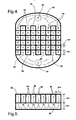
- the inlet manifold channels 44 alternate with the outlet manifold channels 46 to define rectangular cells with X indicating flow into the channels 44, 46 and O indicating flow out of the channels 44, 46 as shown in Figure 4.
- the pressure drop is low because the flow contracts as the flow enters the micro-channels 28 and expands as the flow reverses and flows out of the micro-channels 28.
- a wall-thickness wt is defined or exists between the manifold channels 44, 46 with the inlet manifold channels 44 interleaved with the outlet manifold channels 46 from the outlet edge 32.
- the manifold channels 44, 46 have a manifold-width mw and a manifold-height mh equal to the manifold-thickness mt.
- the lid 24 and the base are circular in exterior configuration and include ears 48 extending radially for mating engagement and defining bolt holes to receive bolts for sealing the lid 24 to the base with the manifold sandwiched therebetween. Appropriate gaskets are sandwiched between the mating parts.
- manifold channels 44, 46 extend transversely across the micro-channels 28 in the base whereby coolant flows from the inlet conduit 40 and into the inlet plenum and into the inlet manifold channels 44 where the flow is forced downward into the micro-channels 28 where the coolant is re-directed up into the outlet manifold channels 46 and out into the outlet plenum for exit out of the outlet conduit 42 to convey heat from a heat source 22 engaging the exterior of the base, as shown in Figures 4 and 5.
- the a base-width bw of the micro-channels 28 is maintained in the range of forty (40) microns to one hundred (100) microns, the base-height bh into the base of the micro-channels 28 in the range of two hundred (200) microns to four hundred (400) microns, the manifold-height through the manifold-thickness of the manifold channels 44, 46 in the range of one thousand (1000) microns to three thousand (3000) microns, and the manifold-width mw of the manifold channels 44, 46 in the range of three hundred and fifty (350) microns to one thousand (1000) microns.
- the micro-channel 28 wall-thickness is fifty (50) microns.
- the heat presenting area of the heat source 22 has a ratio to the active heat transfer area of the bottom surface of the base covered by the micro-channels 28 between seven tenths (0.7) and one (1).
- the invention therefore, provides a method of transferring heat from a heat source 22 to a coolant fluid by flowing coolant into inlet manifold channels 44 extending into a inlet edge 32 of a manifold where the flow is forced downward (indicated by X in Figure 4) into parallel and spaced micro-channels 28 extending across the manifold channels 44, 46 and re-directing the coolant up (indicated by the O in Figure 4) into and out of outlet manifold channels 46 extending into an outlet edge 32 of the manifold and interleaved with the inlet manifold channels 44, and by maintaining a base-width bw of the micro-channels 28 in the range of forty (40) microns to one hundred (100) microns, maintaining a base-height bh of the micro-channels 28 in the range of two hundred (200) microns to four hundred (400) microns, maintaining a manifold-height mh through of the manifold channels 44, 46 in the range of one thousand
- the method is further distinguished by maintaining a flow rate of coolant through the manifold channels 44, 46 and micro-channels 28 between two tenths (0.2) and three tenths (0.3) gallons per minute (GPM).
- a working fluid mover such as a pump 52 moves the flow of cooling fluid, usually a liquid, through a cooling fluid storage tank 54, which stores excess cooling fluid.
- the pump 52 moves the cooling fluid through a heat exchanger to dissipate heat from the cooling fluid.
- the heat exchanger includes a fan 56 and a radiator 58.
- the radiator 58 can be of the well known type including tubes with cooling fins between the tubes to exchange heat between the cooling fluid passing through the tubes and air forced through the radiator 58 by the fan 56.
Landscapes
- Engineering & Computer Science (AREA)
- Physics & Mathematics (AREA)
- Condensed Matter Physics & Semiconductors (AREA)
- General Physics & Mathematics (AREA)
- Computer Hardware Design (AREA)
- Microelectronics & Electronic Packaging (AREA)
- Power Engineering (AREA)
- Thermal Sciences (AREA)
- Mechanical Engineering (AREA)
- General Engineering & Computer Science (AREA)
- Cooling Or The Like Of Semiconductors Or Solid State Devices (AREA)
- Cooling Or The Like Of Electrical Apparatus (AREA)
Abstract
Description
- The subject invention provides heat sink for transferring heat from a heat source to a coolant fluid and a method of operation.
- Electrical components, such as integrated circuits, generate heat that must be dissipated or cooled because heat negatively impacts electrical components. Heat sinks have been employed to dissipate heat and include successive tiers of overlapping channels above a cold plate or base against which the electronic heat component is disposed. Such a heat sink is disclosed in U. S. Patent
5,388,635 to Gruber et al. Typically a flat cold plate or base presents parallel passages or channels all extending the same distance in the cold plate and a manifold plate overlies the cold plate. The electronic component is mounted on the opposite face of the cold plate and coolant flow through the passages to extract heat from the electronic component. - It is a constant goal to fabricate a heat sink which minimizes cost of fabrication yet maximizes the capacity to extract heat, minimizes heat sink mass while maximizing capacity to extract heat.
- The present invention provides a heat sink and method of transferring heat from a heat source to a coolant fluid by flowing coolant into inlet manifold channels extending into a inlet edge of a manifold where the flow is forced downward into parallel and spaced micro-channels extending across the manifold channels and re-directing the coolant up into and out of outlet manifold channels extending into an outlet edge of the manifold and interleaved with the inlet manifold channels. The increased efficiency is obtained by maintaining a base-width of the micro-channels in the range of forty (40) microns to one hundred (100) microns, maintaining a base-height of micro-channels in the range of two hundred (200) microns to four hundred (400) microns, maintaining a manifold-height through the manifold channels in the range of one thousand (1000) microns to three thousand (3000) microns, and maintaining a manifold-width of the manifold channels in the range of three hundred and fifty (350) microns to one thousand (1000) microns.
- Accordingly, the subject invention provides a heat sink that maximizes heat transfer by optimizing the operational relationships of the parameters that affect coolant flow and heat transfer.
- Other advantages of the present invention will be readily appreciated, as the same becomes better understood by reference to the following detailed description when considered in connection with the accompanying drawings wherein:
- Figure 1 is an assembled view showing the lid in phantom of a preferred embodiment of the heat sink of the subject invention;
- Figure 2 is a perspective view, partially cut away and in cross section;
- Figure 3 is an exploded view;
- Figure 4 is a schematic plan view illustrating the relationship between the various flow channels;
- Figure 5 is a schematic cross sectional view illustrating the relationship between the various flow channels; and
- Figure 6 is a schematic view of a system for moving coolant through the heat sink of the subject invention.
- Referring to the Figures, wherein like numerals indicate corresponding parts throughout the several views, a
heat sink 20 is shown generally for transferring heat from aheat source 22 or electronic component to a coolant fluid. - The
heat sink 20 is defined by a housing including alid 24 and abase 26, thebase 26 being a flat cold plate having a top surface and a bottom surface and parallel micro-channels 28 all extending the same distance and each having a base-width bw and a base-height bh into the top surface of the base. - A
manifold plate 30, having a top face and a bottom face to define a manifold-thickness mt, is disposed with the bottom face overlying the micro-channels 28 and having spacededges 32 extending betweenopposite ends 34. Thelid 24 has a periphery engaging the base and aninterior shoulder 36 engaging theends 34 of themanifold plate 30 to define arecessed surface 38 within the periphery and in engagement with the top face of themanifold plate 30. Theedges 32 of themanifold plate 30 define an inlet edge 32 (on the right side of the Figures) and an outlet edge 32 (on the left side of the Figures) each spaced from theshoulder 36 to define an inlet plenum between theinlet edge 32 and theshoulder 36 and an outlet plenum between theoutlet edge 32 and theshoulder 36. Aninlet conduit 40 extends into thelid 24 for fluid flow into the inlet plenum and anoutlet conduit 42 extends into thelid 24 for fluid flow out of the outlet plenum. - The
manifold plate 30 presentsinlet manifold channels 44 extending into theinlet edge 32 andoutlet manifold channels 46 extending into theoutlet edge 32 with each manifold channel terminating in spaced relationship to theopposite edge 32. Theinlet manifold channels 44 alternate with theoutlet manifold channels 46 to define rectangular cells with X indicating flow into thechannels channels manifold channels inlet manifold channels 44 interleaved with theoutlet manifold channels 46 from theoutlet edge 32. Themanifold channels - The
lid 24 and the base are circular in exterior configuration and includeears 48 extending radially for mating engagement and defining bolt holes to receive bolts for sealing thelid 24 to the base with the manifold sandwiched therebetween. Appropriate gaskets are sandwiched between the mating parts. - As will be appreciated, the
manifold channels inlet conduit 40 and into the inlet plenum and into theinlet manifold channels 44 where the flow is forced downward into the micro-channels 28 where the coolant is re-directed up into theoutlet manifold channels 46 and out into the outlet plenum for exit out of theoutlet conduit 42 to convey heat from aheat source 22 engaging the exterior of the base, as shown in Figures 4 and 5. In order to obtain the maximum operating efficiency, the a base-width bw of the micro-channels 28 is maintained in the range of forty (40) microns to one hundred (100) microns, the base-height bh into the base of the micro-channels 28 in the range of two hundred (200) microns to four hundred (400) microns, the manifold-height through the manifold-thickness of themanifold channels manifold channels heat source 22 has a ratio to the active heat transfer area of the bottom surface of the base covered by the micro-channels 28 between seven tenths (0.7) and one (1). - The invention, therefore, provides a method of transferring heat from a
heat source 22 to a coolant fluid by flowing coolant intoinlet manifold channels 44 extending into ainlet edge 32 of a manifold where the flow is forced downward (indicated by X in Figure 4) into parallel and spaced micro-channels 28 extending across themanifold channels outlet manifold channels 46 extending into anoutlet edge 32 of the manifold and interleaved with theinlet manifold channels 44, and by maintaining a base-width bw of the micro-channels 28 in the range of forty (40) microns to one hundred (100) microns, maintaining a base-height bh of the micro-channels 28 in the range of two hundred (200) microns to four hundred (400) microns, maintaining a manifold-height mh through of themanifold channels manifold channels - The method is further distinguished by maintaining a flow rate of coolant through the
manifold channels - Referring to Figure 6, the operation of the
heat sink 20 is incorporated into aliquid cooling system 50 generally shown. A working fluid mover, such as apump 52, moves the flow of cooling fluid, usually a liquid, through a coolingfluid storage tank 54, which stores excess cooling fluid. Thepump 52 moves the cooling fluid through a heat exchanger to dissipate heat from the cooling fluid. The heat exchanger includes afan 56 and aradiator 58. Theradiator 58 can be of the well known type including tubes with cooling fins between the tubes to exchange heat between the cooling fluid passing through the tubes and air forced through theradiator 58 by thefan 56. - Obviously, many modifications and variations of the present invention are possible in light of the above teachings. The invention may be practiced otherwise than as specifically described within the scope of the appended claims.
Claims (6)
- A heat sink (20) for transferring heat from a heat source (22) to a coolant fluid comprising;a housing including a flat base (26) defining a cold plate having parallel micro-channels (28) all extending the same distance and each having a base-width (bw) and a base-height (bh) into said cold plate,a manifold plate (30) having a top face and a bottom face to define a manifold-thickness (mt) with said bottom face overlying said micro-channels (28) and having spaced edges (32) extending between opposite ends (34),said housing presenting a interior shoulder (36) engaging said ends (34) of said manifold plate (30) to define a recessed surface (38) in engagement with said top face of said manifold plate (30),said edges (32) of said manifold plate (30) defining an inlet edge (32) and an outlet edge (32) each spaced from said shoulder (36) to define an inlet plenum between said inlet edge (32) and said shoulder (36) and an outlet plenum between said outlet edge (32) and said shoulder (36),said manifold plate (30) presenting inlet manifold channels (44) extending into said inlet edge (32) and outlet manifold channels (46) extending into said outlet edge (32) with each manifold channel terminating in spaced relationship to the opposite edge (32),said inlet manifold channels (44) alternating with said outlet manifold channels (46) to define a wall-thickness (wt) of the underlying micro-channel (28) so that manifold channels (44, 46) from said inlet edge (32) are interleaved with manifold channels (44, 46) from said outlet edge (32) with said manifold channels (44, 46) having a manifold-width (mw) and a manifold-height (mh) equal to said manifold-thickness (mt),said manifold channels (44, 46) extending transversely across said micro-channels (28) in said base whereby coolant flows from said inlet conduit (40) and into said inlet plenum and into said inlet manifold channels (44) where the flow is forced downward into said micro-channels (28) where the coolant is re-directed up into said outlet manifold channels (46) and out into said outlet plenum for exit out of said outlet conduit (42) to convey heat from a heat source (22) engaging the exterior of said base,said a base-width (bw) of said micro-channels (28) being in the range of forty (40) microns to one hundred (100) microns,said base-height (bh) into said base of said micro-channels (28) being in the range of two hundred (200) microns to four hundred (400) microns,said manifold-height (mh) through said manifold-thickness (mt) of said manifold channels (44, 46) being in the range of one thousand (1000) microns to three thousand (3000) microns, andsaid manifold-width (mw) of said manifold channels (44, 46) in the range of three hundred and fifty (350) microns to one thousand (1000) microns.
- A heat sink (20) as set forth in claim 1 wherein said heat source (22) presents an area having a ratio to the area of said bottom surface of said base between seven tenths (0.7) and one (1).
- A heat sink (20) as set forth in claim 1 wherein said wall-thickness (wt) is fifty (50) microns.
- A heat sink (20) for transferring heat from a heat source (22) to a coolant fluid comprising;a housing including a lid (24) and a base,said base being a flat cold plate having a top surface and a bottom surface and parallel micro-channels (28) all extending the same distance and each having a base-width (bw) and a base-height into said top surface of said base,a manifold plate (30) having a top face and a bottom face to define a manifold-thickness (mt) with said bottom face overlying said micro-channels (28) and having spaced edges (32) extending between opposite ends (34),said lid (24) having a periphery engaging said base and a interior shoulder (36) engaging said ends (34) of said manifold plate (30) to define a recessed surface (38) within said periphery and in engagement with said top face of said manifold plate (30),said edges (32) of said manifold plate (30) defining an inlet edge (32) and an outlet edge (32) each spaced from said shoulder (36) to define an inlet plenum between said inlet edge (32) and said shoulder (36) and an outlet plenum between said outlet edge (32) and said shoulder (36),an inlet conduit (40) in said lid (24) for fluid flow into said inlet plenum,an outlet conduit (42) in said lid (24) for fluid flow out of said outlet plenum,said manifold plate (30) presenting inlet manifold channels (44) extending into said inlet edge (32) and outlet manifold channels (46) extending into said outlet edge (32) with each manifold channel terminating in spaced relationship to the opposite edge (32),said inlet manifold channels (44) alternating with said outlet manifold channels (46) to define a wall-thickness (wt) therebetween so that manifold channels (44, 46) from said inlet edge (32) are interleaved with manifold channels (44, 46) from said outlet edge (32) with said manifold channels (44, 46) having a manifold-width (mw) and a manifold-height (mh) equal to said manifold-thickness (mt),said lid (24) and said base being circular and including ears (48) extending radially for mating engagement and defining bolt holes for sealing said lid (24) to said base with said manifold sandwiched therebetween,a heat source (22) having a heat presenting area in contact with said bottom surface of said base,said manifold channels (44, 46) extending transversely across said micro-channels (28) in said base whereby coolant flows from said inlet conduit (40) and into said inlet plenum and into said inlet manifold channels (44) where the flow is forced downward into said micro-channels (28) where the coolant is re-directed up into said outlet manifold channels (46) and out into said outlet plenum for exit out of said outlet conduit (42) to convey heat from a heat source (22) engaging the exterior of said base,said a base-width (bw) of said micro-channels (28) being in the range of forty (40) microns to one hundred (100) microns,said base-height into said base of said micro-channels (28) being in the range of two hundred (200) microns to four hundred (400) microns,said manifold-height (mh) through said manifold-thickness (mt) of said manifold channels (44, 46) being in the range of one thousand (1000) microns to three thousand (3000) microns, andsaid manifold-width (mw) of said manifold channels (44, 46) in the range of three hundred and fifty (350) microns to one thousand (1000) microns,said wall-thickness (wt) being fifty (50) microns., andsaid heat presenting area of said heat source (22) having a ratio to the active heat transfer area of the bottom surface of the base covered by the micro-channels (28) between seven tenths. and one.
- A method of transferring heat from a heat source (22) to a coolant fluid comprising the steps of;flowing coolant into inlet manifold channels (44) extending into a inlet edge (32) of a manifold where the flow is forced downward into parallel and spaced micro-channels (28) extending across the manifold channels (44, 46) and re-directing the coolant up into and out of outlet manifold channels (46) extending into an outlet edge (32) of the manifold and interleaved with the inlet manifold channels (44), maintaining a base-width (bw) of the micro-channels (28) in the range of forty (40) microns to one hundred (100) microns,maintaining a base-height (bh) of the micro-channels (28) in the range of two hundred (200) microns to four hundred (400) microns,maintaining a manifold-height (mh) through of the manifold channels (44, 46) in the range of one thousand (1000) microns to three thousand (3000) microns, andmaintaining a manifold-width (mw) of the manifold channels (44, 46) in the range of three hundred and fifty (350) microns to one thousand (1000) microns.
- A method as set forth in claim 5 further defined as maintaining a flow rate of coolant through the manifold channels (44, 46) and micro-channels (28) between two tenths (0.2) and three tenths (0.3) gallons per minute.
Applications Claiming Priority (1)
| Application Number | Priority Date | Filing Date | Title |
|---|---|---|---|
| US11/333,655 US7331378B2 (en) | 2006-01-17 | 2006-01-17 | Microchannel heat sink |
Publications (2)
| Publication Number | Publication Date |
|---|---|
| EP1808892A2 true EP1808892A2 (en) | 2007-07-18 |
| EP1808892A3 EP1808892A3 (en) | 2010-05-19 |
Family
ID=37950212
Family Applications (1)
| Application Number | Title | Priority Date | Filing Date |
|---|---|---|---|
| EP07075014A Withdrawn EP1808892A3 (en) | 2006-01-17 | 2007-01-09 | Microchannel heat sink |
Country Status (4)
| Country | Link |
|---|---|
| US (1) | US7331378B2 (en) |
| EP (1) | EP1808892A3 (en) |
| JP (1) | JP2007227902A (en) |
| CN (1) | CN100539819C (en) |
Cited By (14)
| Publication number | Priority date | Publication date | Assignee | Title |
|---|---|---|---|---|
| EP2200080A2 (en) * | 2008-12-22 | 2010-06-23 | General Electric Company | Low Cost Manufacturing of Micro-Channel Heatsink |
| CN102216721B (en) * | 2008-09-30 | 2013-11-13 | 巴尔蒂莫艾尔科伊尔公司 | Modular cooling system |
| US9453691B2 (en) | 2007-08-09 | 2016-09-27 | Coolit Systems, Inc. | Fluid heat exchange systems |
| EP2562809A3 (en) * | 2011-08-22 | 2018-01-24 | General Electric Company | High performance liquid cooled heatsink for igbt modules |
| WO2018142310A1 (en) * | 2017-02-03 | 2018-08-09 | Asetek Danmark A/S | Liquid cooling systems for heat generating devices |
| US10365667B2 (en) | 2011-08-11 | 2019-07-30 | Coolit Systems, Inc. | Flow-path controllers and related systems |
| US10364809B2 (en) | 2013-03-15 | 2019-07-30 | Coolit Systems, Inc. | Sensors, multiplexed communication techniques, and related systems |
| US10415597B2 (en) | 2014-10-27 | 2019-09-17 | Coolit Systems, Inc. | Fluid heat exchange systems |
| US11395443B2 (en) | 2020-05-11 | 2022-07-19 | Coolit Systems, Inc. | Liquid pumping units, and related systems and methods |
| US11452243B2 (en) | 2017-10-12 | 2022-09-20 | Coolit Systems, Inc. | Cooling system, controllers and methods |
| US11473860B2 (en) | 2019-04-25 | 2022-10-18 | Coolit Systems, Inc. | Cooling module with leak detector and related systems |
| US11662037B2 (en) | 2019-01-18 | 2023-05-30 | Coolit Systems, Inc. | Fluid flow control valve for fluid flow systems, and methods |
| US11725886B2 (en) | 2021-05-20 | 2023-08-15 | Coolit Systems, Inc. | Modular fluid heat exchange systems |
| US11994350B2 (en) | 2021-02-07 | 2024-05-28 | Coolit Systems, Inc. | Fluid heat exchange systems |
Families Citing this family (40)
| Publication number | Priority date | Publication date | Assignee | Title |
|---|---|---|---|---|
| US7511957B2 (en) * | 2006-05-25 | 2009-03-31 | International Business Machines Corporation | Methods for fabricating a cooled electronic module employing a thermally conductive return manifold structure sealed to the periphery of a surface to be cooled |
| US20080229580A1 (en) * | 2007-03-23 | 2008-09-25 | Russell Charles Anderson | Method of manufacturing a brazed micro-channel cold plate heat exchanger assembly |
| US8746330B2 (en) * | 2007-08-09 | 2014-06-10 | Coolit Systems Inc. | Fluid heat exchanger configured to provide a split flow |
| US9496200B2 (en) | 2011-07-27 | 2016-11-15 | Coolit Systems, Inc. | Modular heat-transfer systems |
| US9943014B2 (en) | 2013-03-15 | 2018-04-10 | Coolit Systems, Inc. | Manifolded heat exchangers and related systems |
| JP4922903B2 (en) * | 2007-11-27 | 2012-04-25 | 株式会社日立製作所 | Cooling device for electronic equipment |
| US20090154091A1 (en) * | 2007-12-17 | 2009-06-18 | Yatskov Alexander I | Cooling systems and heat exchangers for cooling computer components |
| US8170724B2 (en) | 2008-02-11 | 2012-05-01 | Cray Inc. | Systems and associated methods for controllably cooling computer components |
| US7775062B2 (en) * | 2008-09-15 | 2010-08-17 | Mike Blomquist | Modular cooling system |
| US8120915B2 (en) * | 2008-08-18 | 2012-02-21 | General Electric Company | Integral heat sink with spiral manifolds |
| US7817422B2 (en) * | 2008-08-18 | 2010-10-19 | General Electric Company | Heat sink and cooling and packaging stack for press-packages |
| US8358000B2 (en) * | 2009-03-13 | 2013-01-22 | General Electric Company | Double side cooled power module with power overlay |
| US20100296249A1 (en) * | 2009-05-19 | 2010-11-25 | Beijing AVC Technology Research Center Co., Ltd. | Micro passage cold plate device for a liquid cooling radiator |
| US20110186267A1 (en) * | 2010-02-01 | 2011-08-04 | Suna Display Co. | Heat transfer device with anisotropic thermal conducting micro structures |
| JP4983959B2 (en) * | 2010-04-27 | 2012-07-25 | 株式会社デンソー | Switching power supply |
| US8218320B2 (en) | 2010-06-29 | 2012-07-10 | General Electric Company | Heat sinks with C-shaped manifolds and millichannel cooling |
| US8982558B2 (en) * | 2011-06-24 | 2015-03-17 | General Electric Company | Cooling device for a power module, and a related method thereof |
| DE202012002974U1 (en) * | 2011-07-27 | 2012-07-23 | Coolit Systems Inc. | Fluid heat exchange systems |
| US11092977B1 (en) | 2017-10-30 | 2021-08-17 | Zane Coleman | Fluid transfer component comprising a film with fluid channels |
| CN103188912A (en) * | 2011-12-27 | 2013-07-03 | 刘源 | Lotus-type regular porous metal microchannel heat sink using liquid metal working medium |
| US9353999B2 (en) | 2012-07-30 | 2016-05-31 | Toyota Motor Engineering & Manufacturing North America, Inc. | Cooling apparatuses and electronics modules having branching microchannels |
| US8937810B2 (en) * | 2012-09-14 | 2015-01-20 | International Business Machines Corporation | Electronic assembly with detachable coolant manifold and coolant-cooled electronic module |
| US9477275B2 (en) * | 2013-01-18 | 2016-10-25 | Intel Corporation | Thermal management solution for circuit products |
| JP6394267B2 (en) * | 2014-10-15 | 2018-09-26 | 富士通株式会社 | Cooling device and electronic equipment |
| US9655281B2 (en) * | 2015-06-26 | 2017-05-16 | Seagate Technology Llc | Modular cooling system |
| US9953899B2 (en) | 2015-09-30 | 2018-04-24 | Microfabrica Inc. | Micro heat transfer arrays, micro cold plates, and thermal management systems for cooling semiconductor devices, and methods for using and making such arrays, plates, and systems |
| KR101822304B1 (en) * | 2016-10-24 | 2018-01-25 | 현대자동차주식회사 | Apparatus for cooling battery |
| CN109890171A (en) * | 2017-12-06 | 2019-06-14 | 泽鸿(广州)电子科技有限公司 | Liquid cooling radiation module |
| CN109346446B (en) * | 2018-09-14 | 2020-04-24 | 大连理工大学 | Bonding packaging method suitable for large-size and high-density structure metal microchannel radiator |
| US11804418B2 (en) * | 2019-01-11 | 2023-10-31 | Intel Corporation | Direct liquid micro jet (DLMJ) structures for addressing thermal performance at limited flow rate conditions |
| US10905028B2 (en) * | 2019-05-07 | 2021-01-26 | International Business Machines Corporation | Structure for eliminating the impact of cold plate fouling |
| MX2021013148A (en) * | 2019-05-28 | 2021-12-10 | Mitsui Chemicals Inc | Cooling device and method for manufacturing cooling device. |
| CA3140764A1 (en) | 2019-06-27 | 2020-12-30 | Hypertechnologie Ciara Inc. | Microgap system for cooling electronics with direct contact |
| US11101509B2 (en) * | 2019-10-02 | 2021-08-24 | GM Global Technology Operations LLC | Battery cooling plate with distributed coolant flow |
| JP7352830B2 (en) * | 2019-12-04 | 2023-09-29 | 株式会社オートネットワーク技術研究所 | circuit construct |
| CN111244050B (en) * | 2020-03-27 | 2022-03-25 | 上海先方半导体有限公司 | Chip-level integrated microfluid heat dissipation module and preparation method thereof |
| CN111900143A (en) * | 2020-07-31 | 2020-11-06 | 上海交通大学 | Manifold type high depth-width ratio micro-channel heat exchanger |
| CN114280443A (en) * | 2021-11-03 | 2022-04-05 | 浙江大学杭州国际科创中心 | Power chip manifold type micro-channel heat exchanger testing device |
| CN114136129B (en) * | 2021-12-20 | 2023-02-03 | 山东大学 | Manifold micro-column array flat plate heat exchanger |
| CN116916632B (en) * | 2023-09-08 | 2023-12-01 | 北京航空航天大学 | Microchannel cold plate with staggered shearing flow channels and application method thereof |
Citations (2)
| Publication number | Priority date | Publication date | Assignee | Title |
|---|---|---|---|---|
| US5388635A (en) | 1990-04-27 | 1995-02-14 | International Business Machines Corporation | Compliant fluidic coolant hat |
| US20050211417A1 (en) | 2002-11-01 | 2005-09-29 | Cooligy,Inc. | Interwoven manifolds for pressure drop reduction in microchannel heat exchangers |
Family Cites Families (20)
| Publication number | Priority date | Publication date | Assignee | Title |
|---|---|---|---|---|
| JPS60126854A (en) * | 1983-12-14 | 1985-07-06 | Hitachi Ltd | Cooling device for semiconductor element |
| US4758926A (en) * | 1986-03-31 | 1988-07-19 | Microelectronics And Computer Technology Corporation | Fluid-cooled integrated circuit package |
| US5057908A (en) * | 1990-07-10 | 1991-10-15 | Iowa State University Research Foundation, Inc. | High power semiconductor device with integral heat sink |
| US5453641A (en) * | 1992-12-16 | 1995-09-26 | Sdl, Inc. | Waste heat removal system |
| JPH07249721A (en) * | 1994-03-10 | 1995-09-26 | Fuji Electric Co Ltd | Cooling body for power semiconductor element |
| RU2169977C2 (en) * | 1999-08-16 | 2001-06-27 | ЗАО "Энергомаштехника" | Heat-transfer apparatus for high-power semiconductor lasers |
| FR2830008B1 (en) * | 2001-09-21 | 2004-06-11 | Alstom | PROCESS FOR IMPROVING THE ADHESION PROPERTIES OF A CERAMIC SUBSTRATE OF THE NON-OXIDE FAMILY FOR BONDING |
| US6988534B2 (en) * | 2002-11-01 | 2006-01-24 | Cooligy, Inc. | Method and apparatus for flexible fluid delivery for cooling desired hot spots in a heat producing device |
| DE10246990A1 (en) * | 2002-10-02 | 2004-04-22 | Atotech Deutschland Gmbh | Microstructure cooler and its use |
| US6986382B2 (en) * | 2002-11-01 | 2006-01-17 | Cooligy Inc. | Interwoven manifolds for pressure drop reduction in microchannel heat exchangers |
| WO2004042305A2 (en) * | 2002-11-01 | 2004-05-21 | Cooligy, Inc. | Optimal spreader system, device and method for fluid cooled micro-scaled heat exchange |
| AU2003286855A1 (en) * | 2002-11-01 | 2004-06-07 | Cooligy, Inc. | Method and apparatus for achieving temperature uniformity and hot spot cooling in a heat producing device |
| US7017654B2 (en) * | 2003-03-17 | 2006-03-28 | Cooligy, Inc. | Apparatus and method of forming channels in a heat-exchanging device |
| US7032651B2 (en) * | 2003-06-23 | 2006-04-25 | Raytheon Company | Heat exchanger |
| US20070006996A1 (en) * | 2003-06-27 | 2007-01-11 | Kazuyuki Mikubo | Cooler for electronic equipment |
| WO2005096377A1 (en) * | 2004-03-31 | 2005-10-13 | Hydrocool Pty Limited | A heat exchanger |
| US7139172B2 (en) * | 2004-07-01 | 2006-11-21 | International Business Machines Corporation | Apparatus and methods for microchannel cooling of semiconductor integrated circuit packages |
| US20060096738A1 (en) * | 2004-11-05 | 2006-05-11 | Aavid Thermalloy, Llc | Liquid cold plate heat exchanger |
| US7353859B2 (en) * | 2004-11-24 | 2008-04-08 | General Electric Company | Heat sink with microchannel cooling for power devices |
| DE102005058780A1 (en) * | 2005-12-09 | 2007-06-14 | Forschungszentrum Karlsruhe Gmbh | Micro heat exchanger and the use thereof as a fluid cooler for electronic components |
-
2006
- 2006-01-17 US US11/333,655 patent/US7331378B2/en active Active
-
2007
- 2007-01-09 EP EP07075014A patent/EP1808892A3/en not_active Withdrawn
- 2007-01-16 JP JP2007006924A patent/JP2007227902A/en active Pending
- 2007-01-17 CN CNB2007100083150A patent/CN100539819C/en not_active Expired - Fee Related
Patent Citations (2)
| Publication number | Priority date | Publication date | Assignee | Title |
|---|---|---|---|---|
| US5388635A (en) | 1990-04-27 | 1995-02-14 | International Business Machines Corporation | Compliant fluidic coolant hat |
| US20050211417A1 (en) | 2002-11-01 | 2005-09-29 | Cooligy,Inc. | Interwoven manifolds for pressure drop reduction in microchannel heat exchangers |
Cited By (20)
| Publication number | Priority date | Publication date | Assignee | Title |
|---|---|---|---|---|
| US9453691B2 (en) | 2007-08-09 | 2016-09-27 | Coolit Systems, Inc. | Fluid heat exchange systems |
| US10274266B2 (en) | 2007-08-09 | 2019-04-30 | CoolIT Systems, Inc | Fluid heat exchange sytems |
| CN102216721B (en) * | 2008-09-30 | 2013-11-13 | 巴尔蒂莫艾尔科伊尔公司 | Modular cooling system |
| EP2200080A3 (en) * | 2008-12-22 | 2010-07-07 | General Electric Company | Low Cost Manufacturing of Micro-Channel Heatsink |
| US8929071B2 (en) | 2008-12-22 | 2015-01-06 | General Electric Company | Low cost manufacturing of micro-channel heatsink |
| EP2200080A2 (en) * | 2008-12-22 | 2010-06-23 | General Electric Company | Low Cost Manufacturing of Micro-Channel Heatsink |
| US11714432B2 (en) | 2011-08-11 | 2023-08-01 | Coolit Systems, Inc. | Flow-path controllers and related systems |
| US10365667B2 (en) | 2011-08-11 | 2019-07-30 | Coolit Systems, Inc. | Flow-path controllers and related systems |
| EP2562809A3 (en) * | 2011-08-22 | 2018-01-24 | General Electric Company | High performance liquid cooled heatsink for igbt modules |
| US11661936B2 (en) | 2013-03-15 | 2023-05-30 | Coolit Systems, Inc. | Sensors, multiplexed communication techniques, and related systems |
| US10364809B2 (en) | 2013-03-15 | 2019-07-30 | Coolit Systems, Inc. | Sensors, multiplexed communication techniques, and related systems |
| US10415597B2 (en) | 2014-10-27 | 2019-09-17 | Coolit Systems, Inc. | Fluid heat exchange systems |
| WO2018142310A1 (en) * | 2017-02-03 | 2018-08-09 | Asetek Danmark A/S | Liquid cooling systems for heat generating devices |
| US11452243B2 (en) | 2017-10-12 | 2022-09-20 | Coolit Systems, Inc. | Cooling system, controllers and methods |
| US11662037B2 (en) | 2019-01-18 | 2023-05-30 | Coolit Systems, Inc. | Fluid flow control valve for fluid flow systems, and methods |
| US11473860B2 (en) | 2019-04-25 | 2022-10-18 | Coolit Systems, Inc. | Cooling module with leak detector and related systems |
| US11725890B2 (en) | 2019-04-25 | 2023-08-15 | Coolit Systems, Inc. | Cooling module with leak detector and related systems |
| US11395443B2 (en) | 2020-05-11 | 2022-07-19 | Coolit Systems, Inc. | Liquid pumping units, and related systems and methods |
| US11994350B2 (en) | 2021-02-07 | 2024-05-28 | Coolit Systems, Inc. | Fluid heat exchange systems |
| US11725886B2 (en) | 2021-05-20 | 2023-08-15 | Coolit Systems, Inc. | Modular fluid heat exchange systems |
Also Published As
| Publication number | Publication date |
|---|---|
| US20070163750A1 (en) | 2007-07-19 |
| CN100539819C (en) | 2009-09-09 |
| CN101005753A (en) | 2007-07-25 |
| US7331378B2 (en) | 2008-02-19 |
| EP1808892A3 (en) | 2010-05-19 |
| JP2007227902A (en) | 2007-09-06 |
Similar Documents
| Publication | Publication Date | Title |
|---|---|---|
| US7331378B2 (en) | Microchannel heat sink | |
| US8427832B2 (en) | Cold plate assemblies and power electronics modules | |
| EP2420791A2 (en) | Plate heat exchanger | |
| EP1837909B1 (en) | Heat sink and cooling unit using same | |
| EP1872068B1 (en) | Multi-part heat exchanger | |
| US7017655B2 (en) | Forced fluid heat sink | |
| US7418996B2 (en) | Integrated liquid cooling system for electronic components | |
| CN106918165B (en) | Heat exchanger | |
| JP5135225B2 (en) | Use of a micro heat transfer device as a fluid cooler for micro heat transfer and electronic devices | |
| US20060254752A1 (en) | Radiator and heatsink apparatus having the radiator | |
| US6754076B2 (en) | Stackable liquid cooling pump | |
| US20120241135A1 (en) | Heat exchanger for cooling interior of housing | |
| US20070006998A1 (en) | Heat exchanger with plate projections | |
| EP1705550A2 (en) | Integral liquid cooling unit for a computer | |
| US10004159B2 (en) | Water-cooling radiator unit and device thereof | |
| US20130087317A1 (en) | Internal heat exchanger with external manifolds | |
| EP1702193B1 (en) | A plate heat exchanger | |
| EP2037203A2 (en) | Condenser assembly | |
| CN102751250B (en) | Cooling device | |
| CN111678364A (en) | Micro-channel heat exchanger | |
| US20220007551A1 (en) | Impinging jet coldplate for power electronics with enhanced heat transfer | |
| US20060032611A1 (en) | Semiconductor device cooling apparatus | |
| EP3495761A1 (en) | Heat exchange device | |
| US7265976B1 (en) | Microchannel thermal management system | |
| CN212253773U (en) | Micro-channel heat exchanger |
Legal Events
| Date | Code | Title | Description |
|---|---|---|---|
| PUAI | Public reference made under article 153(3) epc to a published international application that has entered the european phase |
Free format text: ORIGINAL CODE: 0009012 |
|
| AK | Designated contracting states |
Kind code of ref document: A2 Designated state(s): AT BE BG CH CY CZ DE DK EE ES FI FR GB GR HU IE IS IT LI LT LU LV MC NL PL PT RO SE SI SK TR |
|
| AX | Request for extension of the european patent |
Extension state: AL BA HR MK RS |
|
| RAP1 | Party data changed (applicant data changed or rights of an application transferred) |
Owner name: COOLIT SYSTEMS INC. |
|
| PUAL | Search report despatched |
Free format text: ORIGINAL CODE: 0009013 |
|
| AK | Designated contracting states |
Kind code of ref document: A3 Designated state(s): AT BE BG CH CY CZ DE DK EE ES FI FR GB GR HU IE IS IT LI LT LU LV MC NL PL PT RO SE SI SK TR |
|
| AX | Request for extension of the european patent |
Extension state: AL BA HR MK RS |
|
| 17P | Request for examination filed |
Effective date: 20101125 |
|
| AKX | Designation fees paid |
Designated state(s): AT BE BG CH CY CZ DE DK EE ES FI FR GB GR HU IE IS IT LI LT LU LV MC NL PL PT RO SE SI SK TR |
|
| 17Q | First examination report despatched |
Effective date: 20110311 |
|
| GRAJ | Information related to disapproval of communication of intention to grant by the applicant or resumption of examination proceedings by the epo deleted |
Free format text: ORIGINAL CODE: EPIDOSDIGR1 |
|
| GRAP | Despatch of communication of intention to grant a patent |
Free format text: ORIGINAL CODE: EPIDOSNIGR1 |
|
| RIC1 | Information provided on ipc code assigned before grant |
Ipc: H01L 23/473 20060101AFI20150220BHEP Ipc: F28F 9/02 20060101ALI20150220BHEP |
|
| STAA | Information on the status of an ep patent application or granted ep patent |
Free format text: STATUS: THE APPLICATION IS DEEMED TO BE WITHDRAWN |
|
| 18D | Application deemed to be withdrawn |
Effective date: 20150801 |