EP1806210A2 - Travelling robot - Google Patents
Travelling robot Download PDFInfo
- Publication number
- EP1806210A2 EP1806210A2 EP06125153A EP06125153A EP1806210A2 EP 1806210 A2 EP1806210 A2 EP 1806210A2 EP 06125153 A EP06125153 A EP 06125153A EP 06125153 A EP06125153 A EP 06125153A EP 1806210 A2 EP1806210 A2 EP 1806210A2
- Authority
- EP
- European Patent Office
- Prior art keywords
- frame
- wheel
- drive
- driving
- travelling
- Prior art date
- Legal status (The legal status is an assumption and is not a legal conclusion. Google has not performed a legal analysis and makes no representation as to the accuracy of the status listed.)
- Granted
Links
Images


Classifications
-
- B—PERFORMING OPERATIONS; TRANSPORTING
- B25—HAND TOOLS; PORTABLE POWER-DRIVEN TOOLS; MANIPULATORS
- B25J—MANIPULATORS; CHAMBERS PROVIDED WITH MANIPULATION DEVICES
- B25J5/00—Manipulators mounted on wheels or on carriages
- B25J5/007—Manipulators mounted on wheels or on carriages mounted on wheels
-
- B—PERFORMING OPERATIONS; TRANSPORTING
- B60—VEHICLES IN GENERAL
- B60G—VEHICLE SUSPENSION ARRANGEMENTS
- B60G99/00—Subject matter not provided for in other groups of this subclass
-
- B—PERFORMING OPERATIONS; TRANSPORTING
- B62—LAND VEHICLES FOR TRAVELLING OTHERWISE THAN ON RAILS
- B62D—MOTOR VEHICLES; TRAILERS
- B62D61/00—Motor vehicles or trailers, characterised by the arrangement or number of wheels, not otherwise provided for, e.g. four wheels in diamond pattern
- B62D61/12—Motor vehicles or trailers, characterised by the arrangement or number of wheels, not otherwise provided for, e.g. four wheels in diamond pattern with variable number of ground engaging wheels, e.g. with some wheels arranged higher than others, or with retractable wheels
-
- Y—GENERAL TAGGING OF NEW TECHNOLOGICAL DEVELOPMENTS; GENERAL TAGGING OF CROSS-SECTIONAL TECHNOLOGIES SPANNING OVER SEVERAL SECTIONS OF THE IPC; TECHNICAL SUBJECTS COVERED BY FORMER USPC CROSS-REFERENCE ART COLLECTIONS [XRACs] AND DIGESTS
- Y10—TECHNICAL SUBJECTS COVERED BY FORMER USPC
- Y10S—TECHNICAL SUBJECTS COVERED BY FORMER USPC CROSS-REFERENCE ART COLLECTIONS [XRACs] AND DIGESTS
- Y10S901/00—Robots
- Y10S901/01—Mobile robot
Definitions
- the present invention relates to a transportation mechanism for a mobile robot, comprising a main body and at least one front wheel.
- Robots are commonly used to perform dangerous, repetitive, precise, large-scale or high-volume work in place of a human being in fields such as industry, military and in the home. Such robots are often required to move between different areas to perform predetermined operations, and so a travelling/transportation mechanism is necessary for such robots. Thus, research and developments in technology in travelling/transport mechanisms have been undertaken/made which allow a robot to travel smoothly while keeping its balance when travelling on an uneven surface, such as a travelling surface with steps.
- FIGS 1A to 1C are schematic views illustrating travelling states of a known conventional travelling robot 101 having a housing 110, a rear wheel 130 and a driving part 120 to travel on a travel surface S.
- the housing 110 is provided with a function part (not illustrated) for performing a predetermined function.
- the rear wheel 130 is fixedly supported to a rear side of the housing 110 relative to a travelling direction 'd'.
- the rear wheel 130 rotates idly and serves to support the housing 110 on the surface S.
- the driving part 120 has a frame 122, a driving wheel 124 and a front wheel 126.
- the frame 122 is rotatably coupled to the housing 110 by a hinge 112.
- a driving wheel 124 is disposed on the right and left sides of the frame 122 respectively.
- the driving wheel 124 receives driving power from a driving motor 124a and allows the housing 110 to travel in the travelling direction d.
- the front wheel 126 is supported at a front side of the housing 110, in front of the driving wheel 124 with respect to the travelling direction 'd' of the frame 122.
- the single front wheel 126 rotates idly to support the housing 110 on the travel surface S.
- the frame 122 is rotated on the housing 110 by the hinge 112, thus the driving wheel 124 and the front wheel 126 are integrally rotated together with the frame 122.
- a travelling robot 101 such as that described above is disclosed in US Patent No. 5350033 .
- the travelling robot 101 if the travelling robot 101 is able to continue to travel in the travelling direction 'd', as the driving wheel 124 passes and drops down from the obstacle 0 and the rear wheel 130 is positioned onto the obstacle 0, the centre of gravity of the travelling robot 101 rapidly shifts forwards. This may cause the front wheel 126 to abruptly contact the travelling surface S, and cause the housing 112 to sway.
- the above problems regarding the travelling performance of such known travelling robots 101 may become even worse when the height of the obstacles 0 to be negotiated by right and left driving wheels 124 respectively, are different from each other. That is, since the single front wheel 126 and a pair of driving wheels 124 are supported by and integrally linked with the frame 122, the travelling robot 101 may not be capable of dealing with the height difference between the obstacles 0 and thus the slipping of the driving wheel 124 and the swaying of the housing 110 may be further exaggerated.
- the present invention characterised by at least one rear wheel assembly moveably mounted to the main body and comprising a rear frame having a rear wheel mounted to one end of the rear frame, at least one drive wheel assembly pivotably mounted to the main body between the front wheel and the rear wheel assembly and comprising a drive wheel and a drive frame, wherein the rear wheel assembly and the drive wheel assembly are coupled by a linkage member such that movement of the rear wheel assembly can cause movement of the drive wheel assembly and vice versa
- a first end of the linkage member is secured to the drive frame and the opposite end of the linkage member is detached from, but disposed proximate to, an end portion of the rear frame to be pushed by the rear frame during movement of the rear wheel assembly.
- the linkage member is secured proximate to a first end of the drive frame and the drive wheel is mounted proximate to the opposite end of the drive frame, the drive frame being pivotably mounted to the main body intermediate its ends.
- the rear assembly is slidably mounted to the main body to, in use, slide in a substantially vertical plane.
- the end of the rear frame remote from the rear wheel includes a cam and said opposite end of the linkage member comprises a cam follower.
- the rear wheel assembly includes a biasing means to, in use, bias the rear wheel upwardly towards an underside of the main body.
- the drive assembly includes a biasing means to, in use, bias the drive wheel downwardly from an underside of the main body.
- the present invention also provides a travelling robot comprising a body frame having a front wheel, a rear wheel disposed behind the front wheel with respect to a travelling direction of the robot, a rear frame which supports the rear wheel and is supported by the body frame to move vertically relative to a plane of the body frame, a driving wheel disposed between the front wheel and the rear wheel, a driving frame which supports the driving wheel and is coupled to the body frame by a hinge whose axis is parallel to an axis of the driving wheel, and a linkage member coupled to the driving frame to be contacted with or separated from the rear frame as the driving frame is rotated relative to the body frame.
- the hinge is positioned between the driving wheel and the rear wheel.
- the hinge is positioned within a predetermined distance from the centre of gravity of the travelling robot.
- each of the rear wheel, the rear frame, the driving wheel, the driving frame and the linkage member is disposed in pairs, each one of the pair being disposed on opposite sides of the body frame to be operated independently with respect to the other.
- the travelling robot further comprises: a rear pressing member provided between the body frame and the rear frame to press the rear frame upwardly relative to the body frame.
- the travelling robot further comprises a guide provided between the body frame and the rear frame and extends in a direction perpendicular to the axis of the driving wheel to guide the rear frame to allow the rear frame to move vertically relative to the plane of the body frame.
- the rear frame comprises a sliding part to be in sliding contact with the linkage member.
- the travelling robot further comprises: a drive pressing member provided between the body frame and the driving frame to press the driving frame to rotate so that the driving wheel can move downwardly relative to the body frame.
- the present invention also provides a travelling robot comprising a body frame having a front wheel and at least one stopper and at least one driving assembly disposed between the front wheel and the at least one stopper, the at least one driving assembly comprising a drive wheel to drive the robot to travel, a drive frame connected at a first end to the drive wheel and having a hinge disposed at a middle portion thereof to connect to the body frame to enable the drive frame to pivot with respect to the body frame such that a second end thereof and the drive wheel pivot with the drive frame, a rear frame body that extends through the corresponding at least one stopper and is connected at a first end to a rear wheel and has a sliding part connected at a second end thereof wider than the rear frame body to be stopped by the corresponding stopper, and a linkage member connected at one end to the second end of the drive frame to pivot with the drive frame and including another end that contacts the sliding part of the rear frame body to move the rear wheel in a substantially perpendicular direction with respect to the body frame such that when the drive frame pivots by
- the stopper may include a guide recess extending through the frame body
- the rear frame body may comprise: a guide projection which extends along a length thereof along the guide recess, and a rear pressing member which extends along an outer portion of the rear frame body between the stopper and the sliding part of the rear frame body to bias the rear frame body in an upward direction such that the rear pressing member provides a reaction force to a force provided by the linkage member when the linkage member contacts the sliding part to move the rear wheel.
- the travelling robot may further comprise a drive pressing member disposed between the body frame and the driving member to press the driving member to rotate to lower the drive wheel relative to the body frame.
- the drive pressing member may comprise a first end supported by the body frame, a second end supported by the drive frame and an elastic member which biases the one end away from the second end.
- the present invention also provides a travelling robot comprising a body frame having a front wheel, a pair of rear wheel assemblies, and a drive wheel assembly disposed between the front wheel and each of the rear wheel assemblies, the rear wheels being movable in a direction substantially perpendicular to a direction in which the robot travels; and a pair of drive frame assemblies each pivotally connected to the body frame and to a respective one of the drive wheel assemblies to provide movement of the respective drive wheel assembly in the direction substantially perpendicular to the direction in which the robot travels, each drive frame assembly including a linking member extending therefrom to contact the respective rear wheel assembly to link movement of the drive wheel assembly with movement of the respective rear wheel assembly.
- the rear wheel assemblies may comprise a rear frame extending through the body frame and connected at one end to a rear wheel and having another end with a sliding shape and a pressing member to apply a force to the rear frame upward in the direction substantially perpendicular to the direction in which the robot travels.
- a travelling robot 1 comprises a body frame 10, a front wheel 20, a rear wheel 30, a rear frame 40, a driving wheel 50, a driving frame 60 and a linkage member 70.
- the body frame 10 is provided with a function performing part (not illustrated) to perform predetermined functions.
- the travelling robot 1 may be a cleaning robot in which the body frame 10 is equipped with a cleaning part (not illustrated) to clean a travelling surface, a display robot having the body frame 10 which is equipped with a display part (not illustrated) to display information, or a robot to perform any other function.
- the front wheel 20 is supported on a front side of the body frame 10 with respect to a travelling direction 'd' of the robot in use and supports the body frame 10 on the surface being travelled.
- the front wheel 20 is illustrated in Figure 2 as being a single front wheel 20, alternatively a plurality of front wheels 20 may be disposed to be arranged in a direction perpendicular to the travelling direction "d.”
- the front wheel 20 may also have a steering function.
- the front wheel 20 is illustrated to be supported by the body frame 10 to be rotated idly, it may alternatively be driven by a driving motor.
- the rear wheel 30 is disposed on the rear side of the body frame 10 on the opposite side thereof to the front wheel 20.
- the rear wheel 30 is supported by the rear frame 40 and rotates idly.
- the rear wheel 30 may be driven by a driving motor.
- the rear frame 40 supports the rear wheel 30, and is supported by the body frame 10 so as to slide vertically relative to the body frame 10 (or with respect to the direction in which the robot travels). As the rear frame 40 slides vertically relative to the body frame 10, the rear wheel 30 also slides vertically relative to the body frame 10.
- the rear frame 40 has a first stopper 46 to prevent the rear frame 40 from sliding downwardly beyond a predetermined position, so as not to become separated from the body frame 10.
- the rear frame 40 may have a second stopper (not illustrated) to prevent the rear wheel 30 from sliding upwardly beyond a contact position where the rear wheel 30 projects from the body frame 10 to be in contact with the surface being travelled across.
- the rear frame 40 may further include a rear biasing member 80 to bias the rear frame 40 upward by an elastic force.
- the driving wheel 50 is disposed between the front wheel 20 and the rear wheel 30 and is operable to cause the travelling robot 1 to travel forwards in the travelling direction 'd'. However, the driving wheel 50 may also cause the travelling robot 1 to travel backwards in an opposite direction of the travelling direction 'd'.
- the driving wheel 50 receives a driving force from a driving motor 52 and power transmitting unit (not illustrated) is disposed between the driving wheel 50 and the driving motor 52 to transmit the driving force.
- the driving frame 60 supports the driving wheel 50 and is coupled to the body frame 10 by a hinge 62 extending in a parallel direction to an axis of the driving wheel 50. As the driving frame 60 is rotated about the hinge 62 relative to the body frame 10, the driving wheel 50 is also rotated around the hinge 62 so as to move vertically relative to the body frame 10.
- the hinge 62 is disposed between the driving wheel 50 and the rear wheel 30 and connects the driving frame 60 with the body frame 10. (See Figure 3). If the weight of the travelling robot 1 is applied directly downwards to the hinge 62 when the travelling robot 1 is positioned horizontally on the surface being travelled across, the driving frame 60 is biased to rotate in a direction 'a' to force the linkage member 70 to press downwards on the rear frame 40. Therefore, when the travelling robot travels, the linkage member 70 contacts the rear frame 40, so that the rotation of the driving frame 60 vertically biases the rear frame 40 to slide downwards relative to the body frame 10.
- the linkage member 70 is connected to the driving frame 60 to be contacted with or separated from the rear frame 40 as the driving frame 60 is rotated relative to the body frame 10.
- the linkage member 70 is joined to the driving frame 60 to integrally move with the driving frame 60, so that the linkage member 70 is rotated about the hinge 62 when the driving frame 60 is rotated about the hinge 62.
- the linkage member 70 can be in contact with or spaced from the rear frame 40, according to the rotating position of the driving frame 60.
- the linkage member 70 When the linkage member 70 is in contact with the rear frame 40, the linkage member 70 presses the rear frame 40 to slide downwardly relative to the body frame 10. Therefore, the linkage member 70 links the rotation of the driving frame 60 with the vertical sliding of the rear frame 40 so that the driving wheel 50 and the rear wheel 30 are linked to each other to move vertically relative to the plane of the body frame 10. If the driving wheel 50 moves upwardly relative to the body frame 10, the driving frame 60 is rotated about the hinge 62 in the direction "a" and the linkage member 70 contacts the rear frame 40, thereby pressing the rear frame 40 downwards to lower the position of the rear wheel 30 relative to the body frame 10.
- the rear frame 40 presses the linkage member 70 to rotate the driving frame 60 about hinge 62 in a direction "b," thereby lowering the position of the driving wheel 50 relative to the body frame 10.
- the linkage member 70 is separated from the rear frame 40, the rear frame 40 slides vertically relative to the body frame 10 without the restriction caused by the rotation of the driving frame 60.
- the driving wheel 50 and the rear wheel 30 can independently move relative to the body frame 10.
- the linkage member 70 is joined to the driving frame 60 to integrally move with the driving frame 60, according to another embodiment of the present invention, the linkage member 70 may be connected to the driving frame 60 so as to be disposed to be contacted to or separated from the rear frame 40 according to the rotating position of the driving frame 60.
- the hinge 62 can be positioned within a predetermined distance from the centre of gravity of the travelling robot 1. That is, the hinge 62 which joins the driving frame 60 with the body frame 10 can be positioned at the centre of gravity or in an area adjacent to the centre of gravity. Therefore, when the driving frame 60 is rotated relative to the body frame 10 as a result of the travelling robot 1 travelling on an uneven surface, the shift of the centre of gravity of the travelling robot 1 can be minimized, thereby maintaining a traction force of the driving wheel 50 with respect to the surface being travelled on, thus preventing swaying of the body frame 10 and improving the travelling performance of the travelling robot 1.
- the rear wheel 30, the rear frame 40, the driving wheel 50, the driving frame 60 and the linkage member 70 may be provided in pairs disposed on either side of the body frame 10 to operate independently on each side.
- the pair of driving wheels 50 are driven by respective driving motors 52 which are driven independently of each other.
- the pair of rear wheels 30, the pair of rear frames 40, the pair of frames 60 and the pair of linkage members 70 also operate and are driven independently of each other. Therefore, when travelling on a surface which is uneven with respect to each side of the robot, each respective driving wheel 50 can adapt to the respective surface independently of the other.
- the pair of rear wheels 30 are positioned between the pair of driving wheels 50 with respect to the front-rear-centre line of the robot, in other words, the distance between the pair of rear wheels 30 is smaller than the distance between the pair of driving wheels 50. Accordingly, when the travelling robot 1 travels on a travelling surface which is formed with a step having a width narrower than the distance between the pair of driving wheels 50, the pair of rear wheels 30 contact the step to support the body frame 10 (see Figures 6A and 6B).
- the rear wheels 30 may be disposed in a line with the driving wheels 50 and further alternatively, the rear wheels 30 may be disposed such that the distance between the rear wheels 30 is larger than the distance between the driving wheels 50.
- three or more groups of the rear wheel 30, the rear frame 40, the driving wheel 50, the driving frame 60, and the linkage member 70 may be disposed on the body frame 10.
- the travelling robot 1 has a guide 42 (see Figure 3) which is provided between the body frame 10 and the rear frame 40 and extends in a direction p perpendicular to the axis of the driving wheels 50 to guide the rear frame 40 so that the rear frame 40 slides in the direction p, which is also perpendicular to the plane of the body frame 10.
- the guide 42 has a guide projection 42a which extends in the direction p on the rear frame 40 and a guide recess 42b which is formed on the body frame 10 to guide the guide projection 42a. As the guide projection 42a slides along the guide recess 42b, the rear frame 40 slides in the direction p relative to the body frame 10.
- the guide projection 42a may be formed on the body frame 10 and the guide recess 42b may be formed on the rear frame 40.
- the rear frame 40 being supported to slide vertically relative to the body frame 10 is achieved by a simple structure, and so the travelling robot 1 can be easily and cheaply manufactured.
- the rear frame 40 may be supported to slide not in the direction p, but in a decline direction, in a circumferential direction around the hinge 62 or in any other curved direction relative to the body frame 10.
- the rear frame 40 has a sliding part 44 which slidably contacts the linkage member 70.
- the linkage member 70 extends from the driving frame 60 to contact an end of the rear frame 40, and the sliding part 44 has a curved sliding surface 45 which is formed on the end of the rear frame 40.
- the present invention may include the linkage member 70 extending to contact any other portion except for the end of the rear frame 40 and the sliding part 44 may be disposed on a part which is contacted by the linkage member 70.
- the sliding part 44 allows the linkage member 70 to smoothly slide relative to the rear frame 40, so that the rear frame 40 and the driving frame 60 can easily move vertically and be rotated respectively without being restricted by the movement between each other when the rear frame 40 and the driving frame 60 move in different directions.
- the sliding part 44 allows the rear frame 40 to slide in the direction p irrespective of the rotating direction of the driving frame 60.
- the sliding part 44 may be omitted, and the linkage member 70 may be directly contacted with a surface of the rear frame 40.
- the travelling robot 1 has a rear biasing member 80 which is provided between the body frame 10 and the rear frame 40 to bias the rear frame 40 upwardly relative to the body frame 10.
- the rear biasing member 80 has one end which is supported by the body frame 10 and another end which is supported by the rear frame 40 to lift the rear frame 40 relative to the body frame 10 by an elastic force.
- the rear biasing member 80 may be a coil spring, a plate spring or any other spring.
- the travelling robot 1 has a drive biasing member 90 (see, for example, Figures 3 and 4) which is provided between the body frame 10 and the driving frame 60 to rotatably bias the driving frame 60 and thereby lower the driving wheel 50 relative to the body frame 10.
- the drive biasing member 90 has one end which is supported by the body frame 10 and another end which is supported by the driving frame 60 at an opposite side of the driving frame 60 from which the hinge 62 is disposed.
- the axis of the driving wheel 50 is interposed between the point at which the drive biasing member 90 is supported by the driving frame 60 and the hinge 62.
- the drive biasing member 90 rotatably biases the driving frame 60 in a direction 'b' to lower the driving wheel 50 relative to the body frame 10, and thereby increases a traction force of the driving wheel 50 against the surface being travelled on and prevents the driving wheel 50 from sliding on the that surface.
- the travelling robot 1 is shown travelling on an uneven surface which has a stepped part along the driving direction 'd'.
- the weight of the travelling robot 1 is concentrated on the rear wheel 30, so that the rear frame 40 slides upwardly relative to the body frame 10 (see arrow "A").
- the rear frame 40 presses the linkage member 70 and the linkage member 70 rotates the driving frame 60 around the hinge 62 to lower the driving wheel 50 relative to the body frame 10 (see arrow "B"). Therefore, the driving wheel 50 can maintain enough traction force against the surface S being travelled on to drive the travelling robot 1 without difficulty.
- the driving wheel 50 descends from the step to reach the surface S and then the rear wheel 30 is positioned on the step O. At this moment, the weight of the travelling robot 1 is then concentrated on the rear wheel 30.
- the rear wheel 30 then moves upwardly relative to the body frame 10 (see arrow "A") and the linkage member 70 is pressed by the rear frame 40, causing the driving frame 60 to be rotated (see arrow "B") so that the driving wheel 50 moves downwardly relative to the body frame 10. Therefore, the driving wheel 50 contacts the travelling surface 0 which is lower than the stepped surface 0 to ensure the proper traction force to drive the travelling robot 1.
- the linkage member 70 links the rotation of the driving frame 60 with the vertical sliding of the rear frame 40. As a result, it is ensured that the driving wheel 50 has enough traction force and the body frame 10 is prevented from contacting the stepped surface 0.
- the travelling robot 1 is shown travelling on a surface S which is formed with a stepped surface 0 whose width is narrower than the distance between the driving wheels 50. While the driving wheels 50 contact the surface S, the rear wheels 30 contact the stepped surface 0. The weight of the travelling robot 1 is then concentrated on the rear wheels 30, so that the rear frame 40 slides upwardly relative to the body frame 10 (see arrow "A"'). Since the surface S which the driving wheels 50 are in contact with is lower than the stepped surface 0 which the rear wheels 30 are in contact with, the driving wheels 50 further move downwardly relative to the body frame 10 as compared to the situation shown in Figures 5A to 5C or that of the robot 1 travelling on any other ordinary surface. Therefore, the driving frame 60 is rotated to allow the linkage member 70 to be separated from the rear frame 40 (see arrow "B'").
- the driving frame 60 and the rear frame 40 can move independently with respect to each other. Although the driving frame 60 can be rotated through a considerable rotating angle, the rear frame 40 may not slide upwardly more than a predetermined position and the rear frame 40 is not secured to the driving frame 60. Thus, the rear wheel 30 reaches a position where it projects by a minimum distance from the underside of the body frame 10, in order to prevent the body frame 10 from contacting the stepped surface 0.
- the driving frame 60 and the rear frame 40 are not attached to each other, the driving frame 60 is not restricted by the limited position of the rear frame 40 and so may rotate around the hinge 62. Therefore, the driving wheel 50 may move downwardly relative to the body frame 10 enough to contact the travelling surface S, so that it can ensure enough traction force.
Abstract
Description
- The present invention relates to a transportation mechanism for a mobile robot, comprising a main body and at least one front wheel.
- Robots are commonly used to perform dangerous, repetitive, precise, large-scale or high-volume work in place of a human being in fields such as industry, military and in the home. Such robots are often required to move between different areas to perform predetermined operations, and so a travelling/transportation mechanism is necessary for such robots. Thus, research and developments in technology in travelling/transport mechanisms have been undertaken/made which allow a robot to travel smoothly while keeping its balance when travelling on an uneven surface, such as a travelling surface with steps.
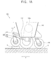
- Figures 1A to 1C are schematic views illustrating travelling states of a known
conventional travelling robot 101 having ahousing 110, arear wheel 130 and a drivingpart 120 to travel on a travel surface S. Thehousing 110 is provided with a function part (not illustrated) for performing a predetermined function. Therear wheel 130 is fixedly supported to a rear side of thehousing 110 relative to a travelling direction 'd'. Therear wheel 130 rotates idly and serves to support thehousing 110 on the surface S. - The
driving part 120 has aframe 122, adriving wheel 124 and afront wheel 126. Theframe 122 is rotatably coupled to thehousing 110 by ahinge 112. Adriving wheel 124 is disposed on the right and left sides of theframe 122 respectively. Thedriving wheel 124 receives driving power from adriving motor 124a and allows thehousing 110 to travel in the travelling direction d. Thefront wheel 126 is supported at a front side of thehousing 110, in front of thedriving wheel 124 with respect to the travelling direction 'd' of theframe 122. The singlefront wheel 126 rotates idly to support thehousing 110 on the travel surface S. Theframe 122 is rotated on thehousing 110 by thehinge 112, thus thedriving wheel 124 and thefront wheel 126 are integrally rotated together with theframe 122. Atravelling robot 101 such as that described above is disclosed inUS Patent No. 5350033 . - However, when such a
robot 101 is not always capable of smoothly negotiating anobstacle 0, such as a step, its travelling performance may be deteriorated. As illustrated in Figure 1A, as thetravelling robot 101 mounts theobstacle 0, thefront wheel 126 is first lifted onto theobstacle 0. As this happens, theframe 122 is rotated about thehinge 112 in direction 'a' so that thehousing 112 maintains its balance. - As illustrated in Figure 1B, when the
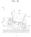
travelling robot 101 further travels in the direction 'd', thedriving wheel 124 then climbs up theobstacle 0, resulting in the centre of gravity of thetravelling robot 101 shifting backward and being disposed over therear wheel 130. This may result in thedriving wheel 124 not receiving sufficient traction force to drive therobot 101 forward and the rotatingdriving wheel 124 slipping on theobstacle 0. - Referring to Figure 1C, if the
travelling robot 101 is able to continue to travel in the travelling direction 'd', as thedriving wheel 124 passes and drops down from theobstacle 0 and therear wheel 130 is positioned onto theobstacle 0, the centre of gravity of thetravelling robot 101 rapidly shifts forwards. This may cause thefront wheel 126 to abruptly contact the travelling surface S, and cause thehousing 112 to sway. - The above problems regarding the travelling performance of such known travelling
robots 101 may become even worse when the height of theobstacles 0 to be negotiated by right and left drivingwheels 124 respectively, are different from each other. That is, since the singlefront wheel 126 and a pair ofdriving wheels 124 are supported by and integrally linked with theframe 122, thetravelling robot 101 may not be capable of dealing with the height difference between theobstacles 0 and thus the slipping of thedriving wheel 124 and the swaying of thehousing 110 may be further exaggerated. - It is therefore an object of the present invention to provide a travelling robot and travelling mechanism for such a robot, which substantially alleviates or overcomes the problems mentioned above.
- Accordingly, the present invention characterised by at least one rear wheel assembly moveably mounted to the main body and comprising a rear frame having a rear wheel mounted to one end of the rear frame, at least one drive wheel assembly pivotably mounted to the main body between the front wheel and the rear wheel assembly and comprising a drive wheel and a drive frame, wherein the rear wheel assembly and the drive wheel assembly are coupled by a linkage member such that movement of the rear wheel assembly can cause movement of the drive wheel assembly and vice versa
- In a preferred embodiment, a first end of the linkage member is secured to the drive frame and the opposite end of the linkage member is detached from, but disposed proximate to, an end portion of the rear frame to be pushed by the rear frame during movement of the rear wheel assembly.
- Preferably, the linkage member is secured proximate to a first end of the drive frame and the drive wheel is mounted proximate to the opposite end of the drive frame, the drive frame being pivotably mounted to the main body intermediate its ends.
- Preferably, the rear assembly is slidably mounted to the main body to, in use, slide in a substantially vertical plane.
- In a preferred embodiment, the end of the rear frame remote from the rear wheel includes a cam and said opposite end of the linkage member comprises a cam follower.
- Preferably, the rear wheel assembly includes a biasing means to, in use, bias the rear wheel upwardly towards an underside of the main body.
- Conveniently, the drive assembly includes a biasing means to, in use, bias the drive wheel downwardly from an underside of the main body.
- The present invention also provides a travelling robot comprising a body frame having a front wheel, a rear wheel disposed behind the front wheel with respect to a travelling direction of the robot, a rear frame which supports the rear wheel and is supported by the body frame to move vertically relative to a plane of the body frame, a driving wheel disposed between the front wheel and the rear wheel, a driving frame which supports the driving wheel and is coupled to the body frame by a hinge whose axis is parallel to an axis of the driving wheel, and a linkage member coupled to the driving frame to be contacted with or separated from the rear frame as the driving frame is rotated relative to the body frame.
- According to the exemplary embodiment of the present invention, the hinge is positioned between the driving wheel and the rear wheel.
- According to the exemplary embodiment of the present invention, the hinge is positioned within a predetermined distance from the centre of gravity of the travelling robot.
- According to the exemplary embodiment of the present invention, each of the rear wheel, the rear frame, the driving wheel, the driving frame and the linkage member is disposed in pairs, each one of the pair being disposed on opposite sides of the body frame to be operated independently with respect to the other.
- According to the exemplary embodiment of the present invention, the travelling robot further comprises: a rear pressing member provided between the body frame and the rear frame to press the rear frame upwardly relative to the body frame.
- According to the exemplary embodiment of the present invention, the travelling robot further comprises a guide provided between the body frame and the rear frame and extends in a direction perpendicular to the axis of the driving wheel to guide the rear frame to allow the rear frame to move vertically relative to the plane of the body frame.
- According to the exemplary embodiment of the present invention, the rear frame comprises a sliding part to be in sliding contact with the linkage member. According to the exemplary embodiment of the present invention, the travelling robot further comprises: a drive pressing member provided between the body frame and the driving frame to press the driving frame to rotate so that the driving wheel can move downwardly relative to the body frame.
- The present invention also provides a travelling robot comprising a body frame having a front wheel and at least one stopper and at least one driving assembly disposed between the front wheel and the at least one stopper, the at least one driving assembly comprising a drive wheel to drive the robot to travel, a drive frame connected at a first end to the drive wheel and having a hinge disposed at a middle portion thereof to connect to the body frame to enable the drive frame to pivot with respect to the body frame such that a second end thereof and the drive wheel pivot with the drive frame, a rear frame body that extends through the corresponding at least one stopper and is connected at a first end to a rear wheel and has a sliding part connected at a second end thereof wider than the rear frame body to be stopped by the corresponding stopper, and a linkage member connected at one end to the second end of the drive frame to pivot with the drive frame and including another end that contacts the sliding part of the rear frame body to move the rear wheel in a substantially perpendicular direction with respect to the body frame such that when the drive frame pivots by a predetermined amount, the drive wheel and the rear wheel move in the direction substantially perpendicular with respect to the body frame.
- According to the exemplary embodiment of the present invention, the stopper may include a guide recess extending through the frame body, and the rear frame body may comprise: a guide projection which extends along a length thereof along the guide recess, and a rear pressing member which extends along an outer portion of the rear frame body between the stopper and the sliding part of the rear frame body to bias the rear frame body in an upward direction such that the rear pressing member provides a reaction force to a force provided by the linkage member when the linkage member contacts the sliding part to move the rear wheel.
- According to the exemplary embodiment of the present invention, the travelling robot may further comprise a drive pressing member disposed between the body frame and the driving member to press the driving member to rotate to lower the drive wheel relative to the body frame.
- According to the exemplary embodiment of the present invention, the drive pressing member may comprise a first end supported by the body frame, a second end supported by the drive frame and an elastic member which biases the one end away from the second end.
- The present invention also provides a travelling robot comprising a body frame having a front wheel, a pair of rear wheel assemblies, and a drive wheel assembly disposed between the front wheel and each of the rear wheel assemblies, the rear wheels being movable in a direction substantially perpendicular to a direction in which the robot travels; and a pair of drive frame assemblies each pivotally connected to the body frame and to a respective one of the drive wheel assemblies to provide movement of the respective drive wheel assembly in the direction substantially perpendicular to the direction in which the robot travels, each drive frame assembly including a linking member extending therefrom to contact the respective rear wheel assembly to link movement of the drive wheel assembly with movement of the respective rear wheel assembly.
- According to the exemplary embodiment of the present invention, the rear wheel assemblies may comprise a rear frame extending through the body frame and connected at one end to a rear wheel and having another end with a sliding shape and a pressing member to apply a force to the rear frame upward in the direction substantially perpendicular to the direction in which the robot travels.
- Preferred embodiments of the present invention will now be described, by way of example only, with reference to the accompanying drawings, in which:
- Figures 1A to 1C are schematic views illustrating travelling stages of a conventional travelling robot;
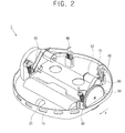
- Figure 2 is a perspective view of a travelling robot according to an embodiment of the present invention;
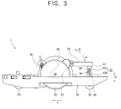
- Figure 3 is a side view of the travelling robot in Figure 2;
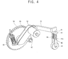
- Figure 4 is a perspective view of a main part of the travelling robot in Figure 2;
- Figures 5A to 5C are side views illustrating the travelling stages of the travelling robot in Figure 2; and
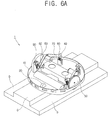
- Figures 6A and 6B are views illustrating other travelling stages of the travelling robot in Figure 2.
- Referring to Figures 2 to 4, a
travelling robot 1 comprises abody frame 10, afront wheel 20, arear wheel 30, arear frame 40, adriving wheel 50, adriving frame 60 and alinkage member 70. Thebody frame 10 is provided with a function performing part (not illustrated) to perform predetermined functions. Thetravelling robot 1 may be a cleaning robot in which thebody frame 10 is equipped with a cleaning part (not illustrated) to clean a travelling surface, a display robot having thebody frame 10 which is equipped with a display part (not illustrated) to display information, or a robot to perform any other function. - The
front wheel 20 is supported on a front side of thebody frame 10 with respect to a travelling direction 'd' of the robot in use and supports thebody frame 10 on the surface being travelled. Though thefront wheel 20 is illustrated in Figure 2 as being a singlefront wheel 20, alternatively a plurality offront wheels 20 may be disposed to be arranged in a direction perpendicular to the travelling direction "d." Thefront wheel 20 may also have a steering function. Further, although thefront wheel 20 is illustrated to be supported by thebody frame 10 to be rotated idly, it may alternatively be driven by a driving motor. - The
rear wheel 30 is disposed on the rear side of thebody frame 10 on the opposite side thereof to thefront wheel 20. Therear wheel 30 is supported by therear frame 40 and rotates idly. In an alternative embodiment however, therear wheel 30 may be driven by a driving motor. - The
rear frame 40 supports therear wheel 30, and is supported by thebody frame 10 so as to slide vertically relative to the body frame 10 (or with respect to the direction in which the robot travels). As therear frame 40 slides vertically relative to thebody frame 10, therear wheel 30 also slides vertically relative to thebody frame 10. Therear frame 40 has afirst stopper 46 to prevent therear frame 40 from sliding downwardly beyond a predetermined position, so as not to become separated from thebody frame 10. Also, therear frame 40 may have a second stopper (not illustrated) to prevent therear wheel 30 from sliding upwardly beyond a contact position where therear wheel 30 projects from thebody frame 10 to be in contact with the surface being travelled across. According to another embodiment of the present invention, therear frame 40 may further include arear biasing member 80 to bias therear frame 40 upward by an elastic force. - The
driving wheel 50 is disposed between thefront wheel 20 and therear wheel 30 and is operable to cause the travellingrobot 1 to travel forwards in the travelling direction 'd'. However, thedriving wheel 50 may also cause the travellingrobot 1 to travel backwards in an opposite direction of the travelling direction 'd'. Thedriving wheel 50 receives a driving force from a drivingmotor 52 and power transmitting unit (not illustrated) is disposed between thedriving wheel 50 and the drivingmotor 52 to transmit the driving force. - The driving
frame 60 supports thedriving wheel 50 and is coupled to thebody frame 10 by ahinge 62 extending in a parallel direction to an axis of thedriving wheel 50. As the drivingframe 60 is rotated about thehinge 62 relative to thebody frame 10, thedriving wheel 50 is also rotated around thehinge 62 so as to move vertically relative to thebody frame 10. - The
hinge 62 is disposed between thedriving wheel 50 and therear wheel 30 and connects the drivingframe 60 with thebody frame 10. (See Figure 3). If the weight of the travellingrobot 1 is applied directly downwards to thehinge 62 when the travellingrobot 1 is positioned horizontally on the surface being travelled across, the drivingframe 60 is biased to rotate in a direction 'a' to force thelinkage member 70 to press downwards on therear frame 40. Therefore, when the travelling robot travels, thelinkage member 70 contacts therear frame 40, so that the rotation of the drivingframe 60 vertically biases therear frame 40 to slide downwards relative to thebody frame 10. - The
linkage member 70 is connected to the drivingframe 60 to be contacted with or separated from therear frame 40 as the drivingframe 60 is rotated relative to thebody frame 10. Thelinkage member 70 is joined to the drivingframe 60 to integrally move with the drivingframe 60, so that thelinkage member 70 is rotated about thehinge 62 when the drivingframe 60 is rotated about thehinge 62. However, thelinkage member 70 can be in contact with or spaced from therear frame 40, according to the rotating position of the drivingframe 60. - When the
linkage member 70 is in contact with therear frame 40, thelinkage member 70 presses therear frame 40 to slide downwardly relative to thebody frame 10. Therefore, thelinkage member 70 links the rotation of the drivingframe 60 with the vertical sliding of therear frame 40 so that thedriving wheel 50 and therear wheel 30 are linked to each other to move vertically relative to the plane of thebody frame 10. If thedriving wheel 50 moves upwardly relative to thebody frame 10, the drivingframe 60 is rotated about thehinge 62 in the direction "a" and thelinkage member 70 contacts therear frame 40, thereby pressing therear frame 40 downwards to lower the position of therear wheel 30 relative to thebody frame 10. In contrast, if therear wheel 30 moves upwardly relative to thebody frame 10, therear frame 40 presses thelinkage member 70 to rotate the drivingframe 60 abouthinge 62 in a direction "b," thereby lowering the position of thedriving wheel 50 relative to thebody frame 10. When thelinkage member 70 is separated from therear frame 40, therear frame 40 slides vertically relative to thebody frame 10 without the restriction caused by the rotation of the drivingframe 60. In this case, thedriving wheel 50 and therear wheel 30 can independently move relative to thebody frame 10. - Although the
linkage member 70 is joined to the drivingframe 60 to integrally move with the drivingframe 60, according to another embodiment of the present invention, thelinkage member 70 may be connected to the drivingframe 60 so as to be disposed to be contacted to or separated from therear frame 40 according to the rotating position of the drivingframe 60. - The
hinge 62 can be positioned within a predetermined distance from the centre of gravity of the travellingrobot 1. That is, thehinge 62 which joins the drivingframe 60 with thebody frame 10 can be positioned at the centre of gravity or in an area adjacent to the centre of gravity. Therefore, when the drivingframe 60 is rotated relative to thebody frame 10 as a result of the travellingrobot 1 travelling on an uneven surface, the shift of the centre of gravity of the travellingrobot 1 can be minimized, thereby maintaining a traction force of thedriving wheel 50 with respect to the surface being travelled on, thus preventing swaying of thebody frame 10 and improving the travelling performance of the travellingrobot 1. - The
rear wheel 30, therear frame 40, thedriving wheel 50, the drivingframe 60 and thelinkage member 70 may be provided in pairs disposed on either side of thebody frame 10 to operate independently on each side. In this case, the pair of drivingwheels 50 are driven byrespective driving motors 52 which are driven independently of each other. The pair ofrear wheels 30, the pair ofrear frames 40, the pair offrames 60 and the pair oflinkage members 70 also operate and are driven independently of each other. Therefore, when travelling on a surface which is uneven with respect to each side of the robot, eachrespective driving wheel 50 can adapt to the respective surface independently of the other. - The pair of
rear wheels 30 are positioned between the pair of drivingwheels 50 with respect to the front-rear-centre line of the robot, in other words, the distance between the pair ofrear wheels 30 is smaller than the distance between the pair of drivingwheels 50. Accordingly, when the travellingrobot 1 travels on a travelling surface which is formed with a step having a width narrower than the distance between the pair of drivingwheels 50, the pair ofrear wheels 30 contact the step to support the body frame 10 (see Figures 6A and 6B). In an alternative embodiment of the present invention however, therear wheels 30 may be disposed in a line with the drivingwheels 50 and further alternatively, therear wheels 30 may be disposed such that the distance between therear wheels 30 is larger than the distance between the drivingwheels 50. Also, in yet another embodiment of the present invention, three or more groups of therear wheel 30, therear frame 40, thedriving wheel 50, the drivingframe 60, and thelinkage member 70 may be disposed on thebody frame 10. - The travelling
robot 1 has a guide 42 (see Figure 3) which is provided between thebody frame 10 and therear frame 40 and extends in a direction p perpendicular to the axis of the drivingwheels 50 to guide therear frame 40 so that therear frame 40 slides in the direction p, which is also perpendicular to the plane of thebody frame 10. Theguide 42 has aguide projection 42a which extends in the direction p on therear frame 40 and aguide recess 42b which is formed on thebody frame 10 to guide theguide projection 42a. As theguide projection 42a slides along theguide recess 42b, therear frame 40 slides in the direction p relative to thebody frame 10. According to another embodiment of the present invention, theguide projection 42a may be formed on thebody frame 10 and theguide recess 42b may be formed on therear frame 40. - The
rear frame 40 being supported to slide vertically relative to thebody frame 10 is achieved by a simple structure, and so the travellingrobot 1 can be easily and cheaply manufactured. In an alternative embodiment of the present invention, therear frame 40 may be supported to slide not in the direction p, but in a decline direction, in a circumferential direction around thehinge 62 or in any other curved direction relative to thebody frame 10. - The
rear frame 40 has a slidingpart 44 which slidably contacts thelinkage member 70. Thelinkage member 70 extends from the drivingframe 60 to contact an end of therear frame 40, and the slidingpart 44 has a curved slidingsurface 45 which is formed on the end of therear frame 40. Alternatively however, the present invention may include thelinkage member 70 extending to contact any other portion except for the end of therear frame 40 and the slidingpart 44 may be disposed on a part which is contacted by thelinkage member 70. - The sliding
part 44 allows thelinkage member 70 to smoothly slide relative to therear frame 40, so that therear frame 40 and the drivingframe 60 can easily move vertically and be rotated respectively without being restricted by the movement between each other when therear frame 40 and the drivingframe 60 move in different directions. The slidingpart 44 allows therear frame 40 to slide in the direction p irrespective of the rotating direction of the drivingframe 60. According to another embodiment of the present invention, the slidingpart 44 may be omitted, and thelinkage member 70 may be directly contacted with a surface of therear frame 40. - The travelling
robot 1 has arear biasing member 80 which is provided between thebody frame 10 and therear frame 40 to bias therear frame 40 upwardly relative to thebody frame 10. Therear biasing member 80 has one end which is supported by thebody frame 10 and another end which is supported by therear frame 40 to lift therear frame 40 relative to thebody frame 10 by an elastic force. Thus, when an external force is not applied to therear frame 40, therear frame 40 is prevented from descending and projecting from the underside of thebody frame 10. Therear biasing member 80 may be a coil spring, a plate spring or any other spring. - The travelling
robot 1 has a drive biasing member 90 (see, for example, Figures 3 and 4) which is provided between thebody frame 10 and the drivingframe 60 to rotatably bias the drivingframe 60 and thereby lower thedriving wheel 50 relative to thebody frame 10. Thedrive biasing member 90 has one end which is supported by thebody frame 10 and another end which is supported by the drivingframe 60 at an opposite side of the drivingframe 60 from which thehinge 62 is disposed. Thus, the axis of thedriving wheel 50 is interposed between the point at which thedrive biasing member 90 is supported by the drivingframe 60 and thehinge 62. Thedrive biasing member 90 rotatably biases the drivingframe 60 in a direction 'b' to lower thedriving wheel 50 relative to thebody frame 10, and thereby increases a traction force of thedriving wheel 50 against the surface being travelled on and prevents thedriving wheel 50 from sliding on the that surface. - Hereinafter, an operation of the travelling robot according to an embodiment of the present invention will be described with reference to Figures 5A to 6B.
- Referring to Figures 5A to 5C, the travelling
robot 1, is shown travelling on an uneven surface which has a stepped part along the driving direction 'd'. Referring to Figure 5A, as thefront wheel 20 climbs up the steppedsurface 0, the weight of the travellingrobot 1 is concentrated on therear wheel 30, so that therear frame 40 slides upwardly relative to the body frame 10 (see arrow "A"). As this happens, therear frame 40 presses thelinkage member 70 and thelinkage member 70 rotates the drivingframe 60 around thehinge 62 to lower thedriving wheel 50 relative to the body frame 10 (see arrow "B"). Therefore, thedriving wheel 50 can maintain enough traction force against the surface S being travelled on to drive the travellingrobot 1 without difficulty. - Referring to Figure 5B, when the travelling
robot 1 further travels and then thedriving wheel 50 climbs up the steppedsurface 0, the weight of the travellingrobot 1 is concentrated on thedriving wheel 50, so that thedriving wheel 50 moves upwardly relative to thebody frame 10, and the drivingframe 60 is rotated around thehinge 62 so that thelinkage member 70 can press the rear frame 40 (see arrow "C"). Thelinkage member 70 lowers therear frame 40 relative to the body frame 10 (see arrow "D"), so that therear wheel 30 contacts the surface S being travelled on which is lower than the steppedsurface 0. Therefore, thedriving wheel 50 can maintain enough traction force and therear wheel 30 is supported on the surface S, thereby preventing thebody frame 10 from coming into contact with the surface S being travelled on. - Referring now to Figure 5C, as the travelling
robot 1 continues to travel, thedriving wheel 50 descends from the step to reach the surface S and then therear wheel 30 is positioned on the step O. At this moment, the weight of the travellingrobot 1 is then concentrated on therear wheel 30. Therear wheel 30 then moves upwardly relative to the body frame 10 (see arrow "A") and thelinkage member 70 is pressed by therear frame 40, causing the drivingframe 60 to be rotated (see arrow "B") so that thedriving wheel 50 moves downwardly relative to thebody frame 10. Therefore, thedriving wheel 50 contacts the travellingsurface 0 which is lower than the steppedsurface 0 to ensure the proper traction force to drive the travellingrobot 1. - As described above, when the travelling
robot 1 travels on the surface S which includes the steppedsurface 0, as the position on which the weight of the travellingrobot 1 is concentrated is changed, thelinkage member 70 links the rotation of the drivingframe 60 with the vertical sliding of therear frame 40. As a result, it is ensured that thedriving wheel 50 has enough traction force and thebody frame 10 is prevented from contacting the steppedsurface 0. - Referring now to Figures 6A to 6B, the travelling
robot 1 is shown travelling on a surface S which is formed with a steppedsurface 0 whose width is narrower than the distance between the drivingwheels 50. While the drivingwheels 50 contact the surface S, therear wheels 30 contact the steppedsurface 0. The weight of the travellingrobot 1 is then concentrated on therear wheels 30, so that therear frame 40 slides upwardly relative to the body frame 10 (see arrow "A"'). Since the surface S which thedriving wheels 50 are in contact with is lower than the steppedsurface 0 which therear wheels 30 are in contact with, the drivingwheels 50 further move downwardly relative to thebody frame 10 as compared to the situation shown in Figures 5A to 5C or that of therobot 1 travelling on any other ordinary surface. Therefore, the drivingframe 60 is rotated to allow thelinkage member 70 to be separated from the rear frame 40 (see arrow "B'"). - The driving
frame 60 and therear frame 40 can move independently with respect to each other. Although the drivingframe 60 can be rotated through a considerable rotating angle, therear frame 40 may not slide upwardly more than a predetermined position and therear frame 40 is not secured to the drivingframe 60. Thus, therear wheel 30 reaches a position where it projects by a minimum distance from the underside of thebody frame 10, in order to prevent thebody frame 10 from contacting the steppedsurface 0. - Further, since the driving
frame 60 and therear frame 40 are not attached to each other, the drivingframe 60 is not restricted by the limited position of therear frame 40 and so may rotate around thehinge 62. Therefore, thedriving wheel 50 may move downwardly relative to thebody frame 10 enough to contact the travelling surface S, so that it can ensure enough traction force. - Although a few embodiments of the present invention have been shown and described, it will be appreciated by those skilled in the art that changes may be made to these embodiments without departing from the principles of the invention, the scope of which is defined in the appended claims hereafter.
Claims (22)
- A transportation mechanism for a mobile robot, comprising:a main body; andat least one front wheel; characterised byat least one rear wheel assembly moveably mounted to the main body and comprising a rear frame having a rear wheel mounted to one end of the rear frame;at least one drive wheel assembly pivotably mounted to the main body between the front wheel and the rear wheel assembly and comprising a drive wheel and a drive frame;wherein the rear wheel assembly and the drive wheel assembly are coupled by a linkage member such that movement of the rear wheel assembly can cause movement of the drive wheel assembly and vice versa.
- A transportation mechanism for a mobile robot according to claim 1 wherein a first end of the linkage member is secured to the drive frame and the opposite end of the linkage member is detached from, but disposed proximate to, an end portion of the rear frame to be pushed by the rear frame during movement of the rear wheel assembly.
- A transportation mechanism for a mobile robot according to claim 2 wherein the linkage member is secured proximate to a first end of the drive frame and the drive wheel is mounted proximate to the opposite end of the drive frame, the drive frame being pivotably mounted to the main body intermediate its ends.
- A transportation mechanism for a mobile robot according to claim 2 or claim 3 wherein the rear assembly is slidably mounted to the main body to, in use, slide in a substantially vertical plane.
- A transportation mechanism for a mobile robot according to claim 3 or claim 4 wherein the end of the rear frame remote from the rear wheel includes a cam and said opposite end of the linkage member comprises a cam follower.
- A transportation mechanism for a mobile robot according to any of claims 1 - 5 wherein the rear wheel assembly includes a biasing means to, in use, bias the rear wheel upwardly towards an underside of the main body.
- A transportation mechanism for a mobile robot according to any of claims 1 - 6 wherein the drive assembly includes a biasing means to, in use, bias the drive wheel downwardly from an underside of the main body.
- A travelling robot comprising:a body frame having a front wheel;a rear wheel disposed behind the front wheel with respect to a travelling direction of the robot;a rear frame which supports the rear wheel and is supported by the body frame to move vertically relative to a plane of the body frame;a driving wheel disposed between the front wheel and the rear wheel;a driving frame which supports the driving wheel and is coupled to the body frame by a hinge whose axis is parallel to an axis of the driving wheel; anda linkage member coupled to the driving frame to be contacted with or separated from the rear frame as the driving frame is rotated relative to the body frame.
- The travelling robot according to claim 8, wherein the hinge is positioned between the driving wheel and the rear wheel.
- The travelling robot according to claim 8, wherein the hinge is positioned within a predetermined distance from the centre of gravity of the travelling robot.
- The travelling robot according to claim 8, wherein each of the rear wheel, the rear frame, the driving wheel, the driving frame and the linkage member is disposed in pairs, each one of the pair being disposed on opposite sides of the body frame to be operated independently with respect to the other.
- The travelling robot according to claim 8, further comprising:a rear pressing member provided between the body frame and the rear frame to press the rear frame upwardly relative to the body frame.
- The travelling robot according to any one of claims 8 through 12, further comprising:a guide provided between the body frame and the rear frame and extends in a direction perpendicular to the axis of the driving wheel to guide the rear frame to allow the rear frame to move vertically relative to the plane of the body frame.
- The travelling robot according to claim 13, wherein the rear frame comprises a sliding part to be in sliding contact with the linkage member.
- The travelling robot according to claim 13, further comprising:a drive pressing member provided between the body frame and the driving frame to press the driving frame to rotate so that the driving wheel can move downwardly relative to the body frame.
- A travelling robot comprising:a body frame having a front wheel and at least one stopper; andat least one driving assembly disposed between the front wheel and the at least one stopper, the at least one driving assembly comprising:a drive wheel to drive the robot to travel,a drive frame connected at a first end to the drive wheel and having a hinge disposed at a middle portion thereof to connect to the body frame to enable the drive frame to pivot with respect to the body frame such that a second end thereof and the drive wheel pivot with the drive frame,a rear frame body that extends through the corresponding at least one stopper and is connected at a first end to a rear wheel and has a sliding part connected at a second end thereof wider than the rear frame body to be stopped by the corresponding stopper, anda linkage member connected at one end to the second end of the drive frame to pivot with the drive frame and including another end that contacts the sliding part of the rear frame body to move the rear wheel in a substantially perpendicular direction with respect to the body frame such that when the drive frame pivots by a predetermined amount, the drive wheel and the rear wheel move in the direction substantially perpendicular with respect to the body frame.
- The travelling robot according to claim 16, wherein
the stopper includes a guide recess extending through the frame body, and
the rear frame body comprises:a guide projection which extends along a length thereof along the guide recess, anda rear pressing member which extends along an outer portion of the rear frame body between the stopper and the sliding part of the rear frame body to bias the rear frame body in an upward direction such that the rear pressing member provides a reaction force to a force provided by the linkage member when the linkage member contacts the sliding part to move the rear wheel. - The travelling robot according to claim 17, further comprising:a drive pressing member disposed between the body frame and the driving member to press the driving member to rotate to lower the drive wheel relative to the body frame.
- The travelling robot according to claim 18, wherein the drive pressing member comprises a first end supported by the body frame, a second end supported by the drive frame and an elastic member which biases the one end away from the second end.
- The travelling robot as claimed in any one of claims 16 through 19, wherein the at least one stopper comprises a first stopper disposed at one side of the rear portion of the frame body and a second stopper disposed at another side of the rear portion of the frame body, and
the at least one drive assembly comprises first and second drive assemblies to correspond with the first and second stoppers, respectively. - A travelling robot comprising:a body frame having a front wheel, a pair of rear wheel assemblies, and a drive wheel assembly disposed between the front wheel and each of the rear wheel assemblies, the rear wheels being movable in a direction substantially perpendicular to a direction in which the robot travels; anda pair of drive frame assemblies each pivotally connected to the body frame and to a respective one of the drive wheel assemblies to provide movement of the respective drive wheel assembly in the direction substantially perpendicular to the direction in which the robot travels, each drive frame assembly including a linking member extending therefrom to contact the respective rear wheel assembly to link movement of the drive wheel assembly with movement of the respective rear wheel assembly.
- The travelling robot according to claim 21, wherein the rear wheel assemblies comprise:a rear frame extending through the body frame and connected at one end to a rear wheel and having another end with a sliding shape; anda pressing member to apply a force to the rear frame upward in the direction substantially perpendicular to the direction in which the robot travels.
Applications Claiming Priority (1)
| Application Number | Priority Date | Filing Date | Title |
|---|---|---|---|
| KR1020050117170A KR100670202B1 (en) | 2005-12-02 | 2005-12-02 | Traveling robot |
Publications (3)
| Publication Number | Publication Date |
|---|---|
| EP1806210A2 true EP1806210A2 (en) | 2007-07-11 |
| EP1806210A3 EP1806210A3 (en) | 2011-07-27 |
| EP1806210B1 EP1806210B1 (en) | 2019-09-11 |
Family
ID=38013967
Family Applications (1)
| Application Number | Title | Priority Date | Filing Date |
|---|---|---|---|
| EP06125153.4A Expired - Fee Related EP1806210B1 (en) | 2005-12-02 | 2006-11-30 | Travelling robot |
Country Status (4)
| Country | Link |
|---|---|
| US (1) | US7673710B2 (en) |
| EP (1) | EP1806210B1 (en) |
| KR (1) | KR100670202B1 (en) |
| CN (1) | CN100475583C (en) |
Cited By (9)
| Publication number | Priority date | Publication date | Assignee | Title |
|---|---|---|---|---|
| ES2350352A1 (en) * | 2010-10-18 | 2011-01-21 | Pal Robotics, S.L. | Robot traction device comprising at least one drive wheel and an odometer (Machine-translation by Google Translate, not legally binding) |
| WO2012091804A3 (en) * | 2010-12-30 | 2013-07-18 | Irobot Corporation | Operating a mobile robot |
| EP2743038A1 (en) * | 2012-12-17 | 2014-06-18 | Vorwerk & Co. Interholding GmbH | Assembly for overcoming a procedural obstacle |
| WO2014118520A1 (en) * | 2013-01-29 | 2014-08-07 | Dyson Technology Limited | Mobile robot |
| US8918213B2 (en) | 2010-05-20 | 2014-12-23 | Irobot Corporation | Mobile human interface robot |
| US8918209B2 (en) | 2010-05-20 | 2014-12-23 | Irobot Corporation | Mobile human interface robot |
| US8930019B2 (en) | 2010-12-30 | 2015-01-06 | Irobot Corporation | Mobile human interface robot |
| US9014848B2 (en) | 2010-05-20 | 2015-04-21 | Irobot Corporation | Mobile robot system |
| EP3117753A4 (en) * | 2014-03-13 | 2017-12-27 | Samsung Electronics Co., Ltd. | Driving unit and cleaning robot comprising same |
Families Citing this family (21)
| Publication number | Priority date | Publication date | Assignee | Title |
|---|---|---|---|---|
| US7721829B2 (en) * | 2005-11-29 | 2010-05-25 | Samsung Electronics Co., Ltd. | Traveling robot |
| KR101017924B1 (en) * | 2008-08-01 | 2011-03-04 | 호야로봇 (주) | Mobile robot included servo-wheel for topography conquest |
| KR101173949B1 (en) * | 2009-12-31 | 2012-08-16 | 한국기술교육대학교 산학협력단 | Horizontal maintenance robot |
| KR101304229B1 (en) * | 2010-08-19 | 2013-09-05 | 덕산메카시스 주식회사 | Remote-controlled attack Device with Launching |
| GB2494444B (en) * | 2011-09-09 | 2013-12-25 | Dyson Technology Ltd | Drive arrangement for a mobile robot |
| GB2494443B (en) | 2011-09-09 | 2013-08-07 | Dyson Technology Ltd | Autonomous surface treating appliance |
| US10846497B2 (en) | 2011-12-05 | 2020-11-24 | Adasa Inc. | Holonomic RFID reader |
| US11093722B2 (en) | 2011-12-05 | 2021-08-17 | Adasa Inc. | Holonomic RFID reader |
| KR101984575B1 (en) * | 2012-06-25 | 2019-09-03 | 엘지전자 주식회사 | Robot Cleaner and Controlling Method for the same |
| KR101386011B1 (en) * | 2012-12-07 | 2014-04-16 | 서울대학교산학협력단 | Passive transformable wheel and robot having the wheel |
| US9908573B2 (en) * | 2015-07-09 | 2018-03-06 | Facebook, Inc. | Self-balancing robot |
| US9975258B2 (en) | 2015-07-09 | 2018-05-22 | Facebook, Inc. | Air flow cooling system and self balancing robot incorporating the same |
| US9759267B2 (en) | 2015-07-09 | 2017-09-12 | Facebook, Inc. | Torque limiting clutch for use with robot arm |
| CN105128978B (en) * | 2015-09-21 | 2018-01-12 | 上海未来伙伴机器人有限公司 | A kind of robot chassis and service robot |
| CN105835988B (en) * | 2016-05-17 | 2017-12-12 | 苏州斯锐奇机器人有限公司 | A kind of indoor service mobile underpan |
| US10451222B2 (en) * | 2017-07-12 | 2019-10-22 | Saudi Arabian Oil Company | Magnetic crawler vehicle with passive rear-facing apparatus |
| KR102595853B1 (en) * | 2019-03-11 | 2023-10-30 | 삼성전자주식회사 | Robot device including elastic covering |
| US20220386833A1 (en) * | 2019-10-02 | 2022-12-08 | Lg Electronics Inc. | Robot cleaner |
| US11345201B2 (en) * | 2020-03-24 | 2022-05-31 | Baker Hughes Holdings Llc | Vehicle suspension with coupled, pivoting, opposing support legs |
| KR102640104B1 (en) * | 2021-11-23 | 2024-02-27 | 주식회사 에이텍에이피 | Driving system of care robot for living-alone elder |
| CN114212166B (en) * | 2021-12-17 | 2023-06-02 | 清华大学 | Obstacle surmounting robot |
Citations (1)
| Publication number | Priority date | Publication date | Assignee | Title |
|---|---|---|---|---|
| JPH03186468A (en) | 1989-12-16 | 1991-08-14 | Star Seiki:Kk | Unmanned self-traveling vehicle |
Family Cites Families (19)
| Publication number | Priority date | Publication date | Assignee | Title |
|---|---|---|---|---|
| US3109506A (en) * | 1960-11-04 | 1963-11-05 | Schroter Kurt | Walker-type motor vehicle |
| US3438641A (en) * | 1966-03-31 | 1969-04-15 | Bartholomew M Bradley | Stair climbing wheelchair |
| JPS57186589A (en) | 1981-05-08 | 1982-11-17 | Shinko Electric Co Ltd | Four-wheeled vehicle |
| US4566707A (en) * | 1981-11-05 | 1986-01-28 | Nitzberg Leonard R | Wheel chair |
| US4730684A (en) * | 1986-07-22 | 1988-03-15 | Borge Pedersen | Vehicle |
| US5350033A (en) * | 1993-04-26 | 1994-09-27 | Kraft Brett W | Robotic inspection vehicle |
| CA2120631C (en) * | 1994-04-06 | 2000-02-15 | Gyula Csotonyi | Power driven wheel chair |
| EP1098587A1 (en) | 1998-07-31 | 2001-05-16 | Volker Sommer | Household robot for the automatic suction of dust from the floor surfaces |
| JP2000202792A (en) | 1999-01-14 | 2000-07-25 | Sharp Corp | Cleaning robot |
| JP2000351385A (en) | 1999-06-10 | 2000-12-19 | Ishikawajima Harima Heavy Ind Co Ltd | Automatically guided vehicle |
| US6554086B1 (en) * | 2000-10-27 | 2003-04-29 | Invacare Corporation | Obstacle traversing wheelchair |
| US6443543B1 (en) * | 2001-04-06 | 2002-09-03 | Wayne Chiang | Mobile personal computer |
| KR20040061323A (en) | 2002-12-30 | 2004-07-07 | 엘지전자 주식회사 | A caterpillar control apparatus of robot vacuum cleaner |
| KR100507926B1 (en) * | 2003-06-30 | 2005-08-17 | 삼성광주전자 주식회사 | Device for driving of robot cleaner |
| EP1493418A1 (en) * | 2003-06-30 | 2005-01-05 | Pride Mobility Products Corporation | Suspension system for a powered wheelchair |
| US7264272B2 (en) * | 2004-03-16 | 2007-09-04 | Pride Mobility Products Corporation | Bi-directional anti-tip system for powered wheelchairs |
| US7273118B2 (en) * | 2005-07-25 | 2007-09-25 | Shao-Shih Huang | Electric wheelchair frame |
| US7306247B2 (en) * | 2005-08-01 | 2007-12-11 | Pihsiang Machinery Mfg. Co. | Suspension structure for an electric wheelchair |
| US7398843B2 (en) * | 2005-08-30 | 2008-07-15 | Boston Dynamics, Inc. | Reconfigurable robot drive |
-
2005
- 2005-12-02 KR KR1020050117170A patent/KR100670202B1/en active IP Right Grant
-
2006
- 2006-11-28 US US11/563,861 patent/US7673710B2/en not_active Expired - Fee Related
- 2006-11-30 EP EP06125153.4A patent/EP1806210B1/en not_active Expired - Fee Related
- 2006-12-01 CN CNB2006101633435A patent/CN100475583C/en not_active Expired - Fee Related
Patent Citations (1)
| Publication number | Priority date | Publication date | Assignee | Title |
|---|---|---|---|---|
| JPH03186468A (en) | 1989-12-16 | 1991-08-14 | Star Seiki:Kk | Unmanned self-traveling vehicle |
Cited By (18)
| Publication number | Priority date | Publication date | Assignee | Title |
|---|---|---|---|---|
| US9014848B2 (en) | 2010-05-20 | 2015-04-21 | Irobot Corporation | Mobile robot system |
| US9498886B2 (en) | 2010-05-20 | 2016-11-22 | Irobot Corporation | Mobile human interface robot |
| US9902069B2 (en) | 2010-05-20 | 2018-02-27 | Irobot Corporation | Mobile robot system |
| US9400503B2 (en) | 2010-05-20 | 2016-07-26 | Irobot Corporation | Mobile human interface robot |
| US8918213B2 (en) | 2010-05-20 | 2014-12-23 | Irobot Corporation | Mobile human interface robot |
| US8918209B2 (en) | 2010-05-20 | 2014-12-23 | Irobot Corporation | Mobile human interface robot |
| US8935005B2 (en) | 2010-05-20 | 2015-01-13 | Irobot Corporation | Operating a mobile robot |
| ES2350352A1 (en) * | 2010-10-18 | 2011-01-21 | Pal Robotics, S.L. | Robot traction device comprising at least one drive wheel and an odometer (Machine-translation by Google Translate, not legally binding) |
| US8930019B2 (en) | 2010-12-30 | 2015-01-06 | Irobot Corporation | Mobile human interface robot |
| WO2012091804A3 (en) * | 2010-12-30 | 2013-07-18 | Irobot Corporation | Operating a mobile robot |
| EP2743038A1 (en) * | 2012-12-17 | 2014-06-18 | Vorwerk & Co. Interholding GmbH | Assembly for overcoming a procedural obstacle |
| WO2014118520A1 (en) * | 2013-01-29 | 2014-08-07 | Dyson Technology Limited | Mobile robot |
| JP2016506788A (en) * | 2013-01-29 | 2016-03-07 | ダイソン テクノロジー リミテッド | Mobile robot |
| GB2525105B (en) * | 2013-01-29 | 2016-09-14 | Dyson Technology Ltd | Mobile robot |
| US9883778B2 (en) | 2013-01-29 | 2018-02-06 | Dyson Technology Limited | Mobile robot |
| GB2525105A (en) * | 2013-01-29 | 2015-10-14 | Dyson Technology Ltd | Mobile robot |
| US9950586B2 (en) | 2014-03-13 | 2018-04-24 | Samsung Electronics Co., Ltd. | Driving unit and cleaning robot comprising same |
| EP3117753A4 (en) * | 2014-03-13 | 2017-12-27 | Samsung Electronics Co., Ltd. | Driving unit and cleaning robot comprising same |
Also Published As
| Publication number | Publication date |
|---|---|
| EP1806210A3 (en) | 2011-07-27 |
| CN1974245A (en) | 2007-06-06 |
| CN100475583C (en) | 2009-04-08 |
| US20070137905A1 (en) | 2007-06-21 |
| EP1806210B1 (en) | 2019-09-11 |
| US7673710B2 (en) | 2010-03-09 |
| KR100670202B1 (en) | 2007-01-16 |
Similar Documents
| Publication | Publication Date | Title |
|---|---|---|
| EP1806210A2 (en) | Travelling robot | |
| EP1806209A2 (en) | Travelling robot | |
| US8469383B2 (en) | Midwheel drive wheelchair with independent front and rear suspension | |
| JP4458165B2 (en) | Conveyor | |
| CA2246854A1 (en) | Transporting device | |
| EP3739658B1 (en) | Battery pack for electric work vehicle | |
| JP5212011B2 (en) | Battery powered car | |
| CN114906773B (en) | Fork truck robot and working method | |
| JP2010064501A (en) | Wheel traveling body | |
| CN210133017U (en) | Driving mechanism and automatic guide trolley | |
| JP4788367B2 (en) | Wire rope operation mechanism | |
| JP3207541U (en) | Travel aid for hand pallet truck | |
| CN101327887B (en) | Drive for vertical lifts | |
| US20070035109A1 (en) | Car | |
| KR100670201B1 (en) | Traveling robot | |
| US20220100382A1 (en) | Reciprocating pedals with dual-levered cam for asymmetric reciprocation | |
| JP5220478B2 (en) | Bicycle with posture maintenance device | |
| CN212473728U (en) | Wheeled robot with parking function | |
| JP5707221B2 (en) | Reach forklift | |
| CN110626984A (en) | Lifting device and carrier | |
| CN210855125U (en) | Lifting device and carrier | |
| CN217778816U (en) | Unmanned transport vehicle | |
| US6840393B2 (en) | Crane assembly | |
| CN219007800U (en) | Supporting device of automatic guiding transport vehicle | |
| CN219601462U (en) | Handling equipment and chassis assembly |
Legal Events
| Date | Code | Title | Description |
|---|---|---|---|
| PUAI | Public reference made under article 153(3) epc to a published international application that has entered the european phase |
Free format text: ORIGINAL CODE: 0009012 |
|
| 17P | Request for examination filed |
Effective date: 20061130 |
|
| AK | Designated contracting states |
Kind code of ref document: A2 Designated state(s): AT BE BG CH CY CZ DE DK EE ES FI FR GB GR HU IE IS IT LI LT LU LV MC NL PL PT RO SE SI SK TR |
|
| AX | Request for extension of the european patent |
Extension state: AL BA HR MK YU |
|
| PUAL | Search report despatched |
Free format text: ORIGINAL CODE: 0009013 |
|
| AK | Designated contracting states |
Kind code of ref document: A3 Designated state(s): AT BE BG CH CY CZ DE DK EE ES FI FR GB GR HU IE IS IT LI LT LU LV MC NL PL PT RO SE SI SK TR |
|
| AX | Request for extension of the european patent |
Extension state: AL BA HR MK RS |
|
| AKX | Designation fees paid |
Designated state(s): DE FR SE |
|
| RAP1 | Party data changed (applicant data changed or rights of an application transferred) |
Owner name: SAMSUNG ELECTRONICS CO., LTD. |
|
| GRAP | Despatch of communication of intention to grant a patent |
Free format text: ORIGINAL CODE: EPIDOSNIGR1 |
|
| INTG | Intention to grant announced |
Effective date: 20190322 |
|
| GRAS | Grant fee paid |
Free format text: ORIGINAL CODE: EPIDOSNIGR3 |
|
| GRAA | (expected) grant |
Free format text: ORIGINAL CODE: 0009210 |
|
| AK | Designated contracting states |
Kind code of ref document: B1 Designated state(s): DE FR SE |
|
| RAP1 | Party data changed (applicant data changed or rights of an application transferred) |
Owner name: SAMSUNG ELECTRONICS CO., LTD. |
|
| REG | Reference to a national code |
Ref country code: DE Ref legal event code: R096 Ref document number: 602006058565 Country of ref document: DE |
|
| PG25 | Lapsed in a contracting state [announced via postgrant information from national office to epo] |
Ref country code: SE Free format text: LAPSE BECAUSE OF FAILURE TO SUBMIT A TRANSLATION OF THE DESCRIPTION OR TO PAY THE FEE WITHIN THE PRESCRIBED TIME-LIMIT Effective date: 20190911 |
|
| REG | Reference to a national code |
Ref country code: DE Ref legal event code: R097 Ref document number: 602006058565 Country of ref document: DE |
|
| PLBE | No opposition filed within time limit |
Free format text: ORIGINAL CODE: 0009261 |
|
| STAA | Information on the status of an ep patent application or granted ep patent |
Free format text: STATUS: NO OPPOSITION FILED WITHIN TIME LIMIT |
|
| 26N | No opposition filed |
Effective date: 20200615 |
|
| PGFP | Annual fee paid to national office [announced via postgrant information from national office to epo] |
Ref country code: DE Payment date: 20201123 Year of fee payment: 15 Ref country code: FR Payment date: 20201120 Year of fee payment: 15 |
|
| REG | Reference to a national code |
Ref country code: DE Ref legal event code: R119 Ref document number: 602006058565 Country of ref document: DE |
|
| PG25 | Lapsed in a contracting state [announced via postgrant information from national office to epo] |
Ref country code: DE Free format text: LAPSE BECAUSE OF NON-PAYMENT OF DUE FEES Effective date: 20220601 |
|
| PG25 | Lapsed in a contracting state [announced via postgrant information from national office to epo] |
Ref country code: FR Free format text: LAPSE BECAUSE OF NON-PAYMENT OF DUE FEES Effective date: 20211130 |