EP1804677B1 - Handle for suturing apparatus - Google Patents
Handle for suturing apparatus Download PDFInfo
- Publication number
- EP1804677B1 EP1804677B1 EP05802122.1A EP05802122A EP1804677B1 EP 1804677 B1 EP1804677 B1 EP 1804677B1 EP 05802122 A EP05802122 A EP 05802122A EP 1804677 B1 EP1804677 B1 EP 1804677B1
- Authority
- EP
- European Patent Office
- Prior art keywords
- needle
- follower
- suture
- arm
- actuator
- Prior art date
- Legal status (The legal status is an assumption and is not a legal conclusion. Google has not performed a legal analysis and makes no representation as to the accuracy of the status listed.)
- Active
Links
- 230000004044 response Effects 0.000 claims description 5
- 230000003993 interaction Effects 0.000 claims description 3
- 239000012780 transparent material Substances 0.000 claims description 3
- 230000000994 depressogenic effect Effects 0.000 description 41
- 238000000034 method Methods 0.000 description 30
- 210000001367 artery Anatomy 0.000 description 27
- 238000003780 insertion Methods 0.000 description 11
- 230000037431 insertion Effects 0.000 description 11
- 210000000689 upper leg Anatomy 0.000 description 11
- 230000007246 mechanism Effects 0.000 description 10
- 230000000881 depressing effect Effects 0.000 description 9
- 210000001105 femoral artery Anatomy 0.000 description 8
- 208000007536 Thrombosis Diseases 0.000 description 6
- 230000017531 blood circulation Effects 0.000 description 6
- 210000004204 blood vessel Anatomy 0.000 description 6
- 239000008280 blood Substances 0.000 description 5
- 210000004369 blood Anatomy 0.000 description 5
- 210000003813 thumb Anatomy 0.000 description 5
- 239000003550 marker Substances 0.000 description 4
- 239000000463 material Substances 0.000 description 4
- 230000036772 blood pressure Effects 0.000 description 3
- 238000001125 extrusion Methods 0.000 description 3
- 210000003195 fascia Anatomy 0.000 description 3
- 210000003811 finger Anatomy 0.000 description 3
- 238000002955 isolation Methods 0.000 description 3
- 239000004033 plastic Substances 0.000 description 3
- 230000000007 visual effect Effects 0.000 description 3
- 208000008883 Patent Foramen Ovale Diseases 0.000 description 2
- 230000009471 action Effects 0.000 description 2
- 230000001154 acute effect Effects 0.000 description 2
- 238000002399 angioplasty Methods 0.000 description 2
- 230000015572 biosynthetic process Effects 0.000 description 2
- 230000006835 compression Effects 0.000 description 2
- 238000007906 compression Methods 0.000 description 2
- 238000007796 conventional method Methods 0.000 description 2
- 230000006378 damage Effects 0.000 description 2
- 229940079593 drug Drugs 0.000 description 2
- 239000003814 drug Substances 0.000 description 2
- 210000002414 leg Anatomy 0.000 description 2
- 238000012986 modification Methods 0.000 description 2
- 230000004048 modification Effects 0.000 description 2
- 230000008569 process Effects 0.000 description 2
- 238000011084 recovery Methods 0.000 description 2
- 238000002560 therapeutic procedure Methods 0.000 description 2
- 238000013519 translation Methods 0.000 description 2
- 206010020772 Hypertension Diseases 0.000 description 1
- 239000004677 Nylon Substances 0.000 description 1
- 240000007643 Phytolacca americana Species 0.000 description 1
- 239000004743 Polypropylene Substances 0.000 description 1
- 239000004792 Prolene Substances 0.000 description 1
- 229910000639 Spring steel Inorganic materials 0.000 description 1
- 206010052428 Wound Diseases 0.000 description 1
- 208000027418 Wounds and injury Diseases 0.000 description 1
- 238000013459 approach Methods 0.000 description 1
- 230000000740 bleeding effect Effects 0.000 description 1
- 208000028831 congenital heart disease Diseases 0.000 description 1
- 238000010276 construction Methods 0.000 description 1
- 230000000694 effects Effects 0.000 description 1
- 230000036541 health Effects 0.000 description 1
- 208000015181 infectious disease Diseases 0.000 description 1
- 208000014674 injury Diseases 0.000 description 1
- 230000002452 interceptive effect Effects 0.000 description 1
- 239000000155 melt Substances 0.000 description 1
- 238000012544 monitoring process Methods 0.000 description 1
- 238000000465 moulding Methods 0.000 description 1
- 229920001778 nylon Polymers 0.000 description 1
- 208000003278 patent ductus arteriosus Diseases 0.000 description 1
- -1 polypropylene Polymers 0.000 description 1
- 229920001155 polypropylene Polymers 0.000 description 1
- 230000009467 reduction Effects 0.000 description 1
- 239000000523 sample Substances 0.000 description 1
- 230000037390 scarring Effects 0.000 description 1
- 230000007480 spreading Effects 0.000 description 1
- 229910001220 stainless steel Inorganic materials 0.000 description 1
- 239000010935 stainless steel Substances 0.000 description 1
- 238000001356 surgical procedure Methods 0.000 description 1
- 229910000811 surgical stainless steel Inorganic materials 0.000 description 1
- 239000010966 surgical stainless steel Substances 0.000 description 1
- 239000003356 suture material Substances 0.000 description 1
- 230000000451 tissue damage Effects 0.000 description 1
- 231100000827 tissue damage Toxicity 0.000 description 1
- 230000007704 transition Effects 0.000 description 1
Images


Classifications
-
- A—HUMAN NECESSITIES
- A61—MEDICAL OR VETERINARY SCIENCE; HYGIENE
- A61B—DIAGNOSIS; SURGERY; IDENTIFICATION
- A61B17/00—Surgical instruments, devices or methods, e.g. tourniquets
- A61B17/0057—Implements for plugging an opening in the wall of a hollow or tubular organ, e.g. for sealing a vessel puncture or closing a cardiac septal defect
-
- A—HUMAN NECESSITIES
- A61—MEDICAL OR VETERINARY SCIENCE; HYGIENE
- A61B—DIAGNOSIS; SURGERY; IDENTIFICATION
- A61B17/00—Surgical instruments, devices or methods, e.g. tourniquets
- A61B17/04—Surgical instruments, devices or methods, e.g. tourniquets for suturing wounds; Holders or packages for needles or suture materials
- A61B17/0469—Suturing instruments for use in minimally invasive surgery, e.g. endoscopic surgery
-
- A—HUMAN NECESSITIES
- A61—MEDICAL OR VETERINARY SCIENCE; HYGIENE
- A61B—DIAGNOSIS; SURGERY; IDENTIFICATION
- A61B17/00—Surgical instruments, devices or methods, e.g. tourniquets
- A61B17/04—Surgical instruments, devices or methods, e.g. tourniquets for suturing wounds; Holders or packages for needles or suture materials
- A61B17/06—Needles ; Sutures; Needle-suture combinations; Holders or packages for needles or suture materials
- A61B17/062—Needle manipulators
- A61B17/0625—Needle manipulators the needle being specially adapted to interact with the manipulator, e.g. being ridged to snap fit in a hole of the manipulator
-
- A—HUMAN NECESSITIES
- A61—MEDICAL OR VETERINARY SCIENCE; HYGIENE
- A61B—DIAGNOSIS; SURGERY; IDENTIFICATION
- A61B17/00—Surgical instruments, devices or methods, e.g. tourniquets
- A61B17/04—Surgical instruments, devices or methods, e.g. tourniquets for suturing wounds; Holders or packages for needles or suture materials
- A61B17/0482—Needle or suture guides
-
- A—HUMAN NECESSITIES
- A61—MEDICAL OR VETERINARY SCIENCE; HYGIENE
- A61B—DIAGNOSIS; SURGERY; IDENTIFICATION
- A61B17/00—Surgical instruments, devices or methods, e.g. tourniquets
- A61B17/00234—Surgical instruments, devices or methods, e.g. tourniquets for minimally invasive surgery
- A61B2017/00292—Surgical instruments, devices or methods, e.g. tourniquets for minimally invasive surgery mounted on or guided by flexible, e.g. catheter-like, means
- A61B2017/00296—Surgical instruments, devices or methods, e.g. tourniquets for minimally invasive surgery mounted on or guided by flexible, e.g. catheter-like, means mounted on an endoscope
-
- A—HUMAN NECESSITIES
- A61—MEDICAL OR VETERINARY SCIENCE; HYGIENE
- A61B—DIAGNOSIS; SURGERY; IDENTIFICATION
- A61B17/00—Surgical instruments, devices or methods, e.g. tourniquets
- A61B2017/00367—Details of actuation of instruments, e.g. relations between pushing buttons, or the like, and activation of the tool, working tip, or the like
-
- A—HUMAN NECESSITIES
- A61—MEDICAL OR VETERINARY SCIENCE; HYGIENE
- A61B—DIAGNOSIS; SURGERY; IDENTIFICATION
- A61B17/00—Surgical instruments, devices or methods, e.g. tourniquets
- A61B17/0057—Implements for plugging an opening in the wall of a hollow or tubular organ, e.g. for sealing a vessel puncture or closing a cardiac septal defect
- A61B2017/00637—Implements for plugging an opening in the wall of a hollow or tubular organ, e.g. for sealing a vessel puncture or closing a cardiac septal defect for sealing trocar wounds through abdominal wall
-
- A—HUMAN NECESSITIES
- A61—MEDICAL OR VETERINARY SCIENCE; HYGIENE
- A61B—DIAGNOSIS; SURGERY; IDENTIFICATION
- A61B17/00—Surgical instruments, devices or methods, e.g. tourniquets
- A61B17/0057—Implements for plugging an opening in the wall of a hollow or tubular organ, e.g. for sealing a vessel puncture or closing a cardiac septal defect
- A61B2017/00646—Type of implements
- A61B2017/00663—Type of implements the implement being a suture
-
- A—HUMAN NECESSITIES
- A61—MEDICAL OR VETERINARY SCIENCE; HYGIENE
- A61B—DIAGNOSIS; SURGERY; IDENTIFICATION
- A61B17/00—Surgical instruments, devices or methods, e.g. tourniquets
- A61B17/0057—Implements for plugging an opening in the wall of a hollow or tubular organ, e.g. for sealing a vessel puncture or closing a cardiac septal defect
- A61B2017/00672—Locating means therefor, e.g. bleed back lumen
-
- A—HUMAN NECESSITIES
- A61—MEDICAL OR VETERINARY SCIENCE; HYGIENE
- A61B—DIAGNOSIS; SURGERY; IDENTIFICATION
- A61B17/00—Surgical instruments, devices or methods, e.g. tourniquets
- A61B17/04—Surgical instruments, devices or methods, e.g. tourniquets for suturing wounds; Holders or packages for needles or suture materials
- A61B17/0469—Suturing instruments for use in minimally invasive surgery, e.g. endoscopic surgery
- A61B2017/0472—Multiple-needled, e.g. double-needled, instruments
-
- A—HUMAN NECESSITIES
- A61—MEDICAL OR VETERINARY SCIENCE; HYGIENE
- A61B—DIAGNOSIS; SURGERY; IDENTIFICATION
- A61B17/00—Surgical instruments, devices or methods, e.g. tourniquets
- A61B17/28—Surgical forceps
- A61B17/29—Forceps for use in minimally invasive surgery
- A61B17/2909—Handles
- A61B2017/2911—Handles rings
-
- A—HUMAN NECESSITIES
- A61—MEDICAL OR VETERINARY SCIENCE; HYGIENE
- A61B—DIAGNOSIS; SURGERY; IDENTIFICATION
- A61B17/00—Surgical instruments, devices or methods, e.g. tourniquets
- A61B17/28—Surgical forceps
- A61B17/29—Forceps for use in minimally invasive surgery
- A61B17/2909—Handles
- A61B2017/2912—Handles transmission of forces to actuating rod or piston
Definitions
- the invention relates generally to a suturing apparatus, such as for applying suture within biological tissue that may not be directly accessible to the physician.
- a relatively small percutaneous incision is made in the femoral or other artery.
- a catheter is inserted through the incision and directed along an arterial path to a target area, such as the heart, to perform one or more procedures, such as an angioplasty or angiogram.
- procedures are intended to be relatively quick 'outpatient' procedures.
- the physician Upon completion of the catheterization procedure, the physician typically creates a 'thrombus patch' by applying direct pressure to the patient's thigh to make the blood around the incision clot. It is very important that the applied pressure does not impede the flow of blood through the femoral artery. As a result, it is commonplace for the physician to apply direct pressure by hand for the first twenty minutes after the procedure. During this time, the physician can feel the pulse to assure the artery is not occluded. Afterwards, the physician typically transfers responsibility to an assistant who then applies direct pressure using sandbags, clamps or other devices. A significant problem with this approach is that it is frequently necessary to apply the pressure for an extended period of time, such as twenty-four hours or longer.
- thrombus patch method Another problem with the thrombus patch method is that the high blood pressure in the artery can cause the thrombus patch to rupture or burst while direct pressure is being applied to the thigh or after direct pressure is removed. This requires the entire process to be reinitiated. If the patch ruptures and is not quickly restored, substantial bleeding can occur, with potentially fatal consequences. Because thrombus patches frequently burst, the patient is often kept in the hospital or catheterization lab overnight for observation. As a result, these 'out-patient' procedures become 'in-patient' procedures, simply because a thrombus patch is often unreliable and/or difficult to create. Staying in the hospital increases patient discomfort and hospital expenses, which are often disproportionate to the actual medical procedure performed.
- a thrombus patch cannot be adequately formed, the physician may need to anesthetize the patient and occlude the blood flow to the artery. At this point, the physician is required to make a large incision in the thigh to allow conventional suturing with a needle, suture the artery with conventional means, restore blood flow to the artery, and suture the incision in the thigh. This results in additional discomfort and expenses for the patient.
- the size and location of the artery make suturing extremely difficult. More specifically, the opening in the thigh is often too small and too deep to provide enough working space for suturing the artery using conventional methods. Thus, in order to suture the vessel using conventional methods, the opening in the thigh would have to be significantly enlarged, thereby further increasing the recovery period and exposing the patient to additional discomfort, undesirable scarring, possible infection and other health risks.
- US 6,562,052 B2 relates to a suturing device and method that allows a physician to remotely suture biological tissue.
- the device includes an elongate body, first and second arms operably connected to the elongated body, whereby each arm mounts an end portion of a suture, and first and second needles, each needle having a distal end and being mounted such that the distal end of the needle is movable to engage respective end portions of said suture.
- the suturing apparatus further includes an actuator which drives the needles to engage the suture non-simultaneously.
- EP 0 870 486 A1 relates to apparatus to remove tissue.
- the apparatus has an outer cannula and an inner cannula received within the outer cannula.
- the cannula are longitudinally movable relative to each other.
- a drive permits advancing of the other cannula to contact the abutment whereby tissue between the other cannula and the abutment is removed.
- US 2004/0068273 A1 relates to an incision closing apparatus for simultaneous insertion of suture needles through adjacent sides of an incision in a fascia layer within a patient.
- An insertion end is sized for insertion through the incision and a shield is retractably extended from the insertion end positioned interior of the fascia layer.
- a plurality of elongated spokes having needles thereon are extended from openings within the insertion end for ejection of needles having attached suture filaments through adjacent sides of the fascia layer incision.
- WO 2004/112618 A3 relates to a surgical stapling device which includes a handle portion, a central body portion and a SULU.
- the SULU includes a proximal body portion, an intermediate pivot member and a tool assembly.
- EP 0 656 191 A2 relates to a surgical clip applier comprising a housing, a pair of handles pivotally connected to opposite sides of the housing, and a jaw blade assembly fixedly connected to the housing.
- the jaw blade assembly includes a pair of jaws for receiving and deforming a clip therebetween and a clip carrier for supplying a series of clips to the jaws.
- the assembly 4 generally comprises a suturing apparatus 6 and a catheter sheath introducer (CSI) 8.
- the suturing apparatus 6 may be used to seal a blood vessel following an interventional catheterization procedure, such as an angiogram, angioplasty or other procedure.
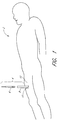
- FIGURE 2 an enlarged view of the treatment site is illustrated. In this view it can be seen that a physician makes an initial incision 10 in an upper thigh region 12 of a patient 2. The physician then inserts a needle (not shown) into the incision 10 such that the needle pierces a femoral artery 14, creating a vessel incision 16 therein.
- the physician When blood bleeds back from the insertion, the physician knows the needle has entered the femoral artery 14. The physician then inserts a guidewire (not shown) through the needle and into the artery 14. The physician may take the needle out and insert a plastic needle (not shown) over the guidewire once the guidewire is in place. The guidewire may then be taken out.
- the CSI 8 is typically a single-lumen catheter with a valve located on its proximal end.
- the valve is configured to prevent extraneous bleed back and/or to introduce medication into the patient's body.
- the vessel incision 16 provides access for medical instruments and probes inside the arterial vessel 14.
- An instrument, such as a therapy catheter, may be advanced through the artery 14 via the CSI 8 to perform a procedure within the body.
- the physician inserts the suturing apparatus 6 through the CSI 8 such that a suture introducer head 20, distally attached to a hollow elongate body 32, enters the first incision 10, passes through the tissue 18 of the patient's thigh 12, and enters the femoral artery 14 through the vessel incision 16.
- the suture arms 24, 24' are deployed and the introducer head 20 of the suturing apparatus is pulled back such that the suture arms contact the inner wall 22 of the femoral artery 14.
- needles are deployed from the introducer head which penetrate the wall 14 of the femoral artery 14 adjacent the incision 16.
- the needles capture suture ends from the suture arms and the needles are then retracted to withdraw the suture ends back through the wall of the femoral artery.
- the arms are then retracted and the entire suturing apparatus is withdrawn such that the suture ends may be tied together to close the incision.
- the suturing apparatus 6 will be described in more detail. Additional details and exemplary methods of operation are described in Applicant's U.S. Pat. Nos. 6,245,079 and 6,562,052 . It will be appreciated that although the device 6 is preferably used for suturing vessel walls 22, the device 6 can be used to suture other tissues such as, by way of example, a patent ductus arteriosus, a patent foramen ovale (PFO), a heart defect, a puncture wound, and the like.
- a patent ductus arteriosus a patent foramen ovale (PFO)
- PFO patent foramen ovale
- the suturing apparatus 6 generally comprises an elongate body 32, an introducer head 20 and a handle portion 100.
- the handle portion 100 allows the physician to operate the suturing apparatus such that suture may be applied to an incision in a very quick and easy manner.
- the handle portion requires very little manipulation during use and may be operated with a single hand if necessary.
- the suturing apparatus may be used to close an incision located deep within the patient's tissue (e.g., in the femoral artery) without requiring the application of pressure over an extended period of time. As a result, the suturing apparatus may substantially reduce the recovery period following a medical procedure, thereby allowing the patient to return home more quickly and substantially reducing costs.
- the dimensions of the suturing apparatus 6 may vary according to the suture site and the biological tissue intended to be sutured.
- the suture introducer head 20 has a diameter of about 0.27 cm (0.105 inches), and the hollow elongate body 32 has a diameter of about 0.25 cm (0.098 inches).
- the handle portion 100 comprises a main housing 102, an arm trigger 104, a needle trigger 106 and an arm release button 108.
- the arm and needle triggers provide actuators for producing movement of internal components within the main housing, which in turn move at least one arm and needle for applying suture to a treatment site.
- the handle portion is constructed such that the arm trigger 104, needle trigger 106 and arm release button 108 may be depressed by the physician in a particular order to extend and retract cooperating suture arms and needles along the introducer head 20 for applying suture to an incision.
- the arm and needle triggers are preferably pivotally coupled to the main housing 102 about pin 110 such that the triggers rotate as they are depressed by the physician. As will be described in more detail below, the pivotal rotation facilitates the cam-like interaction of the triggers with the internal components of the main housing.
- An opening 112 is provided along the main housing 102 for allowing manual retraction of the needles in the event that the needles become stuck in the tissue during retraction. This provides a safety mechanism to ensure that the needles of the suturing apparatus cannot become stuck in the extended position.
- a tool (not shown) is inserted through the opening 112 in the main housing 102 for applying force to assist in the retraction of the needles.
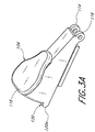
- the arm trigger 104 is shown in isolation. Loops 114, 116 are provided along the distal end of the arm trigger for receiving the pin 110 in the main housing.
- the bottom corner portion 120 along the proximal end portion of the arm trigger is shaped with a protrusion 120A which provides a camming surface for engaging a first slidable follower member in the main housing.
- the protrusion also allows the arm trigger to be held in the depressed position for locking the arms in the deployed condition.
- the top surface 118 of the arm trigger is shaped for engagement with the physician's thumb or finger.
- the needle trigger 106 is shown in isolation.
- Loop 122 is provided along the proximal end of the needle trigger for receiving the pin 110 in the main housing.
- the loop is shaped to fit within the gap between the loops 114, 116 of the arm trigger 104 (see FIGURE 3A ).
- the bottom corner portion 130 along the distal end portion of the needle trigger provides a camming surface for engagement with a second slidable follower member in the main housing.
- the top surface 128 of the needle trigger is shaped for engagement with the physician's thumb or finger.
- the internal components cooperate with the arm and needle triggers 104, 106 (i.e., actuators) and arm release button 108 for effecting movement of the arms and needles during the application of suture. More specifically, the arm and needle triggers actuate the arms and needles by effecting movement of the internal components contained with the main housing.
- the arm and needle triggers each preferably have corner portions 120, 130 shaped with camming surfaces which interact with first and second slidable follower members in the main housing. The follower members are caused to translate longitudinally when the arm or needle triggers are depressed by the physician.
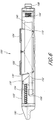
- FIGURE 4 a cross-sectional side view of the handle portion 100 is shown for purposes of illustration. It can be seen that a first follower member 140 is slidably disposed within the interior of the main housing 102. The first follower member 140 is connected to a proximal end of an actuating rod, preferably through a drive wire tab 156 described below, which extends distally through the main housing and elongate body for connection to each of the arms. When the first follower member 140 is in the distal position, as shown in FIGURE 4 , the arms are fully contained within the introducer head.
- each of the arms deploys outward through apertures on the sides of the introducer head.
- the operation of the arms and needles will be described in more detail below.
- longitudinal movement of the first follower member 140 relative to the main housing controls the position of the arms.
- An arm spring 144 provides a biasing force to maintain the first follower member 140 in the distal position in the absence of any external input.
- arm spring is shown for purposes of illustration, any known biasing mechanisms may be used for maintaining the first follower member 140 into the distal position.
- the first follower member 140 is formed with an inclined "cammed" surface 142 along a distal face. As shown in FIGURE 4 , the inclined cammed surface is configured for engagement with the camming surface along the corner portion 120 of the arm trigger 104.
- the corner portion 120 of the arm trigger 104 pushes along the inclined surface 142 of the first follower member 140.
- the downward force acting on the inclined surface results in longitudinal translation of the first follower member.
- the longitudinal force causes the first follower member to slide in a proximal direction (i.e., backward) within the main housing.
- the actuating rod is pulled in a proximal direction, thereby causing the arms to deploy outward through the ports.
- the arm trigger 104 is preferably releasably securable in the fully depressed condition for locking the arms in the deployed condition. As a result, it is not necessary for the physician to apply a constant a force on the arm trigger 104 to maintain the suture arms in the deployed condition.
- the corner portion 120 of the arm trigger is preferably formed with a protrusion 120A.
- FIGURE 7 provides an enlarged view of the corner portion 120 including the protrusion 120A.
- the protrusion is shaped to be captured and held beneath the first follower member 140 when the arm trigger 104 is fully depressed.
- the arm spring 144 urges the first follower member forward (in the distal direction) such that the first follower member abuts the arm trigger and securely holds the protrusion. Accordingly, the cooperation of the protrusion and the first follower member creates a detent mechanism such that the arm trigger is selectively maintained in the depressed position.
- FIGURE 10 provides another perspective view of the corner portion of the arm trigger.
- the arm release button 108 is configured for releasing the protrusion when it is desired to retract the deployable arms.
- the arm release button 108 is preferably provided along a proximal end of the main housing 102 and is configured for engagement with the arm trigger 104.
- An arm release spring 144 may be provided for maintaining the arm release button 108 in the non-depressed condition in the absence of an external input. Accordingly, the arm release button can only act on the arm trigger when a sufficient force is applied to overcome the biasing force of the arm biasing spring 144.
- the arm release button 108 is shown in isolation.
- the arm release button is provided with an elongate member 108A that is configured to contact the corner portion of the arm trigger when the arm trigger is being held in the fully depressed condition. More particularly, the elongate member 108A is configured to urge the arm trigger in the distal direction such that the protrusion is released from the first follower member.
- FIGURE 9 is a cross-sectional view illustrating an alternative arm trigger wherein a section of the corner portion has been cut away to facilitate the release of the arm trigger upon actuation of the arm release button. It will be appreciated that alternative methods may be used to release the arm trigger.
- the arm trigger may be provided with a lip on its upper surface and an actuator may be used to engage the lip to pull the arm trigger back to its initial position.
- a second follower member 150 is slidably disposed within the interior of the main housing at a location distal to the first follower member 140.
- the second follower member 150 is connected to the proximal ends of the elongate needles 70, 70'.
- longitudinal movement of the second follower member 150 relative to the main housing 102 effects the position of the needles.
- the second follower member 150 has a proximal position
- a needle biasing spring 154 engages the second follower member for maintaining the second follower member in the proximal position in the absence of any external input. Although one particular embodiment of a needle biasing spring 154 is shown for purposes of illustration, a wide variety of different biasing mechanisms may be used for biasing the second follower member into the proximal position.
- the second follower member 150 is provided with an inclined "cammed" surface 152 along the proximal face such that the second follower member cooperates with a camming surface along the corner portion 130 of the needle trigger 106 in a manner substantially similar to that of the first follower member. More particularly, as shown in FIGURE 5 , the inclined surface is shaped for slidable engagement with a camming surface of the needle trigger 106.
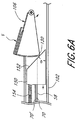
- the camming surface along the corner portion 130 of the needle trigger pushes against the inclined surface 152 of the second follower member 150, as illustrated in the cross-sectional view of FIGURE 6A .
- the force from the needle trigger creates a resulting longitudinal force on the second follower member that causes the second follower member to slide distally relative to the main housing.
- the needles 70, 70' are pushed in a distal direction, thereby causing the distal end portions of the needles to extend outward from the introducer head for engagement with the suture arms.
- the extension of the needles from the introducer head will be described in more detail below.
- the second follower member 150 is contained within a body portion that is integral with the first follower member.
- the body portion provides a slotted track such that the second follower member may be guided proximally and distally during use.
- the first and second follower members are preferably slidably coupled to each other.
- the second follower member may be formed with a longitudinal lumen for slidably receiving the actuating rod 58. Accordingly, the actuating rod 58 may be slid longitudinally by movement of the first follower member without interfering with the second follower member.
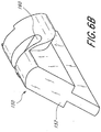
- FIGURE 6B provides a perspective view of the second follower member 150 having an inclined surface 152. It can be seen that the lower portion of the second follower member is thinner in construction.
- the thinner section is configured to fit within a groove in the body portion for guiding the movement of the second follower member, as described above.
- the second follower member is also formed with a slot 160 for receiving a tool through the window 112 in the main housing 102 ( FIGURE 3 ). The tool may be inserted through the window and into the slot. The tool may then be used to slide the second follower member in the event that it sticks, thereby providing a safety mechanism as described above.
- the cammed surface of the first and second follower members is shaped to produce a desired motion in response to actuation of the arm and needle triggers, respectively.
- at least a portion the cammed surface of the second follower member is inclined at about 35° or more relative to the longitudinal axis.
- the angle of inclination is denoted by the symbol ⁇ (alpha) in FIGURE 6A .
- at least a portion of the cammed surface is inclined at about 40° or more relative to the axis.
- at least a portion of the cammed surface is inclined at about 41° relative to the axis.
- at least a portion of the cammed surface is inclined at between about 35-45° relative to the axis.
- At least a portion of the cammed surface is inclined at between about 39-43° relative to the axis. In another variation, at least a portion of the cammed surface is inclined at between about 40-42° relative to the axis. In still another variation, the camming surface is curved. The same preferred ranges also apply to the cammed surface of the first follower member. It will be appreciated that the ratio of trigger movement to needle movement is proportional to the angle of the inclined surface. It has been found that the above angles provide excellent performance while minimizing the diameter of the handle portion. For example, a lower angle would make the follower members more difficult to move due to frictional forces.
- an inclined surface formed with a substantially constant angle provides a substantially directly proportional relationship between trigger movement and needle movement. As a result, the physician is able to advance and retract the needles with great precision and predictability by controlling the movement of the needle trigger.
- the main housing 102 is preferably constructed of a translucent or transparent material, such as plastic, such that the movement of the components within the main housing is visible to the physician.
- the transparency advantageously provides visual feedback to the physician regarding operation of the suturing apparatus.
- markings or other indicia may be provided such that the position of the needles may be easily perceived during use.
- a window may be provided for observing the movement of the internal components or a portion of one or more internal components may extend through the main housing to an exterior surface for purposes of visibility.
- the distal end portion provides one preferred suturing apparatus that may be operated using the improved handle portion described above.
- the distal end portion comprises the suture introducer head 20, a pair of suture arms 24, 24', a pair of suture clasps 56, 56', a pair of suture arm apertures 50, 50', a pair of curved or slanted needle guides 48, 48', a pair of needle apertures 30, 30', a distal end 54, a hole 46, a suture 52 and an actuating rod 58.
- the distal end portion further comprises a pair of needles 70, 70' (see FIGURES 13 through 15 ).
- the suture arms 24, 24' are retracted into the suture arm apertures 50, 50' and the needles 70, 70' are retracted into the needle apertures 30, 30', the arms 24, 24' and the needles 70, 70' are recessed within the suture introducer head 20, as shown in FIGURE 11A . This prevents the arms 24, 24' and the needles 70, 70' from causing tissue damage while the distal end portion passes through a biological structure.
- FIGURES 11B and 11C illustrate the distal end portion of the device 6 ( FIGURE 3 ) with the suture arms 24, 24' partially deployed outwardly from their recessed positions.
- Such deployment is achieved by partially depressing the arm trigger 104, as described above with reference to FIGURES 4 through 6 .
- Depressing the arm trigger 104 translates the first follower member 140 ( FIGURE 4 ) and actuating rod 58 proximally, which brings the suture arms 24, 24' into contact with a pair of proximal inside edges 78, 78' of the suture arm apertures 50, 50'.
- the proximal inside edges 78, 78' force the suture arms 24, 24' into a deployed state.
- the suture arms 24, 24' continue to deploy radially until the arms 24, 24' are substantially parallel with each other and substantially perpendicular to the longitudinal axis of the suture introducer head 20, as shown in FIGURE 15 .
- the suture arms 24, 24' may be "fully” deployed when they reach an acute or obtuse angle relative to each other.
- each of the suture arms 24, 24' comprises a suture clasp 56, 56' which holds an end of the suture 52.
- Each of the suture arms 24, 24' are pre-loaded with the ends of the suture 52 before operation.
- the ends of the suture 52 then pass from the suture clasps 56, 56' to the hole 46 whereby the ends of the suture 52 enter the suture introducer head 20 and are passed proximally through the hollow elongate body 32.
- each end of the suture 52 has a capture portion comprising a loop which is tied onto the ends of the suture claps 56, 56'. It is contemplated, however, that the capture portions are not restricted solely to tied loops, rather other types of capture portions may be utilized such as, by way of example, spheres or ferrules.
- FIGURE 12A illustrates another configuration of a capture portion wherein the end of the suture 52 comprises a flattened distal region 93 having a hole or eyelet 95.
- the suture 52 comprises a strand 91 of deformable material that is preferably monofilament, such as Deklene (from Genzyme), Prolene (from Johnson & Johnson), or Nylon (from Johnson & Johnson).
- the strand 91 is advantageously approximately 0.0254 cm (0.010") thick and has a length that makes it suitable for use in suture procedures.
- the distal end of the strand 91 is heated until the distal end melts or is otherwise plastically or thermally deformed to form a locally deformed region (such as a globule) that is broader than the rest of the strand 91 in at least one dimension (i.e., at least one dimension of the strand 91 has been increased).
- a locally deformed region such as a globule
- the strand 91 may be allowed to cool, and the deformed region may then be flattened by use of a die.
- the die preferably has a relief or recessed portion for accepting the strand 91 and the deformed region.
- a block which preferably also has a recessed portion that mates with the recessed portion, may then be placed over the deformed region.
- the deformed region is then squeezed between the die and the block, resulting in the formation of the flattened distal portion 93 illustrated in FIGURE 12A .
- the flattened distal portion 93 preferably has a thickness that matches the rest of the strand 91.
- the edges of the flattened distal portion 93 may then be trimmed to form a smooth disc portion to reduce the risk of such edges snagging on vessel walls during suturing procedures.
- the eyelet 95 is formed within the flattened distal portion 93.
- a punch such as a hypotube may be used to poke through the flattened distal portion 93, thereby leaving the eyelet 95 within the flattened distal portion 93.
- the eyelet 95 is formed such that a surgical hook or needle may pass through the eyelet 95 in a suturing procedure.
- the flattened distal portion 93 acts as a connector to the hook or needle, allowing the strand 91 to be picked up by the hook or needle.
- Methods for forming the flattened distal region 93 are discussed in greater detail in Applicant's above-mentioned U.S. Patent No. 6,562,052 , entitled SUTURING DEVICE AND METHOD.
- the suture embodiment shown in FIGURE 12A has no knots or ties formed therein which might increase the profile of the suture strand 91 or make it easier for the suture 52 to snag during use.
- This process may advantageously be repeated at the proximal end of the strand 91, resulting in eyelets 95, 95' at both ends of the strand 91, as illustrated in FIGURE 12B .
- the flattened distal portion 93 at one or more of the ends of the strand 91 may be bent (not shown) at an angle with respect to the rest of the strand 91 to facilitate the guiding of a surgical needle through the eyelet 95.
- FIGURE 11C illustrates one preferred configuration of the hollow elongate body 32 which comprises five lumens. Two of the lumens 60, 60' are used to house the needles 70, 70'.
- the needle trigger 106 FIGURE 3
- the needles 70, 70' move distally at substantially the same time.
- the needles 70, 70' may be actuated separately such that one of the needles 70, 70' advances before the other.
- the needles 70, 70' are flexible and preferably made of a material with shape memory, such as SUPERFLEX NITINOLTM.
- the needles 70, 70' may be comprised of spring steel, surgical stainless steel or any variation thereof.
- Each of the needles 70, 70' preferably has a diameter of about 0.05 cm (0.019 inches), but needles with other diameters may be used in accordance with the particular medical procedure contemplated.
- the needle guides 48, 48' cause the needles 70, 70' to bend radially outward.
- a further outward, radial bend preferably is imparted to the needles 70, 70' when they come into contact with a pair of angled surfaces 57, 57' of the suture arms 24, 24'.
- the needles 70, 70' are retracted into the needle lumens 60, 60', the needles 70, 70' resume a straight configuration as a result of their resiliency.
- the suturing apparatus of FIGS. 11A through 15 preferably comprises flexible needles 70, 70', which bend during deployment, it is contemplated that other configurations may advantageously comprise rigid needles which may be permanently straight or curved.
- the hollow elongate body 32 contains a central lumen 64 which is used to house the actuating rod 58.
- Another lumen 62 is used to house the length of the suture 52 to prevent the suture 52 from becoming tangled.
- the suture 52 may be passed through the central lumen 64 along with the actuating rod 58.
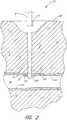
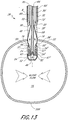
- a fifth lumen 62' is preferably used for "bleed back," which enables the physician to determine whether the distal end 54 of the suture introducer head 20 is positioned within the artery 14. Bleed back is accomplished through the hole 46 at the distal end 54 of the suture introducer head 20, the suture arm apertures 50, 50' and any other openings in the suture introducer head 20. The direction of blood flow for bleed back is indicated by three dashed arrows in FIG. 13 . If the distal end 54 of the suture introducer head 20 is positioned within the artery 14, blood pressure due to blood entering into the hole 46 will be much greater than if the distal end 54 is not within the artery 14.
- the lumen 62' extends to a port (not shown) at a proximal portion of the device 6, whereby the physician can determine the blood pressure within the bleed back lumen 62' by monitoring blood flow from the port.
- the lumen 62' may be attached to a balloon which inflates when the distal end 54 of the suture introducer head 20 passes into the blood vessel 14.
- a pressure sensor may be coupled with the lumen 62' to provide the physician with a numeric blood pressure reading.
- the lumen 62' may be used to inject medication or for diagnostic purposes.
- two thin stripes 66 (only one shown in FIGURE 11C ) marked on the exterior of the hollow elongate body 32 extend along the entire length of the hollow elongate body 32.
- the stripes 66 provide a visual indication of the circumferential location of the needles 70, 70' relative to the hollow elongate body 32.
- the stripes 66 facilitate aligning the needles 70, 70' with the axis of the blood vessel 14, so that needle incisions 80, 80' (see FIGURE 15 ) formed in the vessel wall 22 by the needles 70, 70' will be aligned along a dimension transverse to the flow of blood within the artery 14.
- the hollow elongate body 32 may have only one stripe 66 which denotes the circumferential location of one of the two needles 70, 70'. Because the needles 70, 70' deploy from opposite sides of the suture introducer head 20, knowledge of the location of one needle provides the physician with knowledge of the location of the other needle.
- the exterior surface of the hollow elongate body 32 includes a marker 68 which denotes a proximal position to which the CSI 8 should be partially withdrawn (after the distal portion 26 of the suturing apparatus 6 has been inserted into the blood vessel 14) to expose the needle apertures 30, 30'.
- the partial withdrawal of the CSI 8 is discussed in detail in Applicant's above-mentioned U.S. Patent No. 6,562,052 , entitled SUTURING DEVICE AND METHOD.
- the marker 68 is shown as a visual marker, but may additionally or alternatively be in the form of a ridge, groove, or other physical structure which interacts with a corresponding structure of the CSI 8 to allow the physician to position the CSI 8 using a sense of feel.
- the CSI 8 and the hollow elongate body 32 could be configured to releasably engage or interlock with one another when the CSI 8 reaches a predetermined position along the elongate body 32. It is contemplated that a specially formed CSI 8 comprises such an interlocking structure, and is included within the scope of the invention.
- one or more additional markers may advantageously be provided along the length of the hollow elongate body 32, distal to the marker 68, to indicate other positions of the CSI 8 relative to the elongate body 32, such as the position at which the suture arms 24, 24' are exposed outside the CSI 8.
- the handle portion 100 provides an improved mechanism for quickly and easily actuating the components of the suturing apparatus to apply suture to an incision, such as to close a vessel wall after a surgical procedure.
- each end of a suture has a capture portion comprised of a loop, a sphere or a ferrule.
- the loop, sphere or ferrule may be formed (e.g., by heat molding) with the same suture material as the length of suture.
- the loop, sphere or ferrule may be a separate piece attached (e.g., molded, glued, etc.) onto each end of the length of suture.
- the loop, sphere or ferrule is loaded in respective suture end supports of the arms 24, 24'.
- the remaining length of the suture preferably extends through the hollow elongate body.
- the physician With the CSI 8 extending into the patient's artery 14, the physician then inserts the suture introducer head 20 through the CSI 8 and into the artery 14.
- the CSI 8 is then partially withdrawn along the hollow elongate body 32 to remove the CSI 8 from the artery 14 and to expose the needle apertures 30, 30', as shown in FIGURE 13 .
- the markers 68 ( FIGURE 11C ) on the exterior surface of the hollow elongate body 32 indicate how far the physician should withdraw the CSI 8 to expose the needle apertures 30, 30'.
- the distal end 54 of the suture introducer head 20 has a smooth, rounded surface which prevents injury to the opposite vessel wall 22 when the suture introducer head 20 is inserted into the artery 14.
- blood flow within the artery 14 is uninterrupted because the suture introducer head 20 does not occlude the artery 14.
- the physician may use bleed back through the hole 46 and the lumen 62' ( FIGURE 11C ) to determine when the suture introducer head 20 has entered into the artery 14.
- the arm trigger 104 and needle trigger 106 are each in the non-depressed positions, as depicted in FIGURE 4 .
- the first follower is located in the distal position such that the suture arms are in the retracted condition.
- the second follower is in the proximal position such that the needles are in the retracted condition.
- the actuating rod 58 holds the suture arms 24, 24' in a recessed state within the suture introducer head 20.
- the actuating rod 58 applies a downward force while a pair of deflection surfaces 67, 67' of the suture introducer head 20 apply an inward force on each of the suture arms 24, 24', respectively.
- the combination of these two forces retains the suture arms 24, 24' within the suture arm apertures 50, 50' of the suture introducer head 20.
- Each of the suture clasps 56, 56' comprises an angled slot which holds a looped end of the suture 52 as illustrated in FIGURES 11A through 11C .
- the looped ends of the suture 52 are held securely by the suture clasps 56, 56', but are positioned for easy removal by a pair of suture catches 72, 72' at the tips of the needles 70, 70'.
- the physician depresses the arm trigger 104 ( FIGURE 3 ) to deploy the suture arms 24, 24' as shown in FIGURE 14 .
- Downward movement of the arm trigger acts on the first follower member 140 in the main housing 102, thereby causing the first follower member to translate proximally, which pulls the actuating rod proximally.
- the corner portion 120 of the arm trigger 104 provides a camming surface which engages an inclined cammed surface on the first follower member 140. During this action, the force applied on the arm trigger must be sufficient to overcome the biasing force of the arm spring 144.
- Movement of the first follower member 140 translates the actuating rod 58 proximally, which relieves the downward force applied by the actuating rod 58 and thus also relieves the inward forces applied to the suture arms 24, 24' by the deflection surfaces 67, 67'. This allows the suture arms 24, 24' to assume a partially deployed state as illustrated in FIGURE 14 .
- the actuating rod 58 continues translating proximally, bringing the suture arms 24, 24' into contact with the proximal inside edges 78, 78'.
- the proximal inside edges 78, 78' apply a downward force on each of the suture arms 24, 24', respectively, thereby forcing the suture arms 24, 24' into a fully deployed state as illustrated in FIGURE 15 .
- the protrusion 120A along the corner portion 120 of the arm trigger 104 advances beneath the first follower body 140.
- the arm trigger 104 is maintained in the fully depressed position by the force of the arm spring 144, which pushes the first follower body against the arm trigger.
- the cooperation between the arm trigger and the first follower body advantageously provides a releasable detent mechanism for holding the arm trigger in the depressed position.
- the suture arms 24, 24' preferably have reached a fully extended position and are longitudinally aligned with each other, as illustrated in FIGURE 15 .
- the physician may gently slide the suturing apparatus 6 proximally so that the suture arms 24, 24' contact the interior surface of the vessel wall 22.
- FIGURE 5 illustrates the needle trigger in the non-depressed position.
- FIGURE 6 illustrates the needle trigger in the fully depressed position.
- the camming surface along the corner portion 130 of the needle trigger 106 engages and slides along the cammed surface of the second follower member 150, thereby causing the second follower member to slide longitudinally within the main housing 102 in a distal direction.
- the force applied on the needle trigger 106 must be sufficient to overcome the biasing force of the needle biasing spring 154.
- the second follower member continues to slide distally, thereby advancing the needles distally through the main housing and through the hollow elongate body. As the first and second needles advance distally, the distal ends of the needles extend outward for engagement with the arms.
- the paths taken by the needles 70, 70' are illustrated in FIGURE 15 .
- the needles 70, 70' slide along the needle lumens 60, 60' and out of the suture device 6 through the needle apertures 30, 30', respectively.
- the needles 70, 70' come in contact with the needle insertion guides 48, 48', the needles 70, 70' begin to bend radially outward.
- the needles 70, 70' exit they are guided at a radially outward, acute angle away from the actuating rod 58 by the needle insertion guides 48, 48'.
- the angle of the needle deflection is preferably about 13.2 degrees. Deflection angles between about 10 degrees and about 15 degrees and between about 5 degrees and about 20 degrees are also contemplated.
- the needles 70, 70' penetrate the vessel wall 22 at an angle, thereby creating the needle incisions 80, 80' on opposite sides of the incision 16.
- the needles 70, 70' also preferably bend slightly (radially outward) when they come in contact with the suture arms 24, 24'.
- the angled surfaces 57, 57' of the suture clasps 56, 56' and the suture catches 72, 72' exert a force on each of the looped ends of the suture 52 such that the looped ends remain tied to the suture clasps 56, 56' while the needles 70, 70' pass therein.
- the physician depresses the needle trigger 106 until the suture catches 72, 72' of the needles 70, 70' engage the suture clasps 56, 56' and capture the looped ends of the suture 52.
- the suture arms 24, 24' hold the looped ends of the suture 52 away from the suture introducer head 20 so that the needles 70, 70' pierce the vessel wall 22 and capture the looped ends of the suture 52 outside the perimeter of the suture introducer head 20.
- Mechanical limits prevent additional movement of the needle trigger 106 once the needles 70, 70' have optimally engaged the suture clasps 56, 56'.
- Such resistance signals to the physician that the needles 70, 70' have reached an optimal, predetermined location within the suture clasps 56, 56'.
- the physician advances the needles 70, 70' to the optimal, predetermined location within the suture clasps 56, 56', the physician releases pressure on the needle trigger 106, thereby allowing the needle biasing spring 154 within the handle portion 100 (see FIGURES 4-6 ) to retract the needles 70, 70' proximally.
- This motion causes the needles 70, 70' to withdraw into the needle lumens 60, 60' with the looped ends of the suture 52 attached to the suture catches 72, 72'.
- the suture catches 72, 72' capture the looped ends of the suture 52 held by the suture clasps 56, 56' and pull the looped ends up through the needle incisions 80, 80' as the needles 70, 70' retract proximally.
- the physician may regulate the rate of needle movement by controlling the rate of movement of the needle trigger. From the above, it can be seen that the position of the needles is substantially directly proportional with the position of the needle trigger. Accordingly, by sensing the position of the needle trigger, the physician is provided with a reliable indication of needle position at any given time.
- the physician advantageously controls the position of the needles 70, 70' by depressing and releasing the needle trigger 104.
- the advancement of the needle is achieved by depressing the needle trigger in a controlled manner, while retraction is achieved by allowing the needle spring to retract the needle while the physician regulates the rate of retraction with the needle trigger.
- the physician depresses the arm release button 108 ( FIGURE 3 ) to release the arm trigger 104.
- the arm release button urges the corner portion 120 of the arm trigger 104 in a distal direction such that the protrusion 120A is released from the first follower member 140, thereby allowing the arm trigger 104 to spring back upward.
- the arm biasing spring 144 pushes the first follower member 140 distally, thereby moving the actuating rod 58 distally. This relieves the forces applied to the suture arms 24, 24' by the proximal inside edges 78, 78', allowing the suture arms 24, 24' to assume a relaxed state as illustrated in FIGURE 14 .
- the suture arms 24, 24' move distally until contacting the deflection surfaces 67, 67'. Together with the deflection surfaces 67, 67', the downward force of the actuating rod 58 causes the suture arms 24, 24' to retract into the recessed state within the suture introducer head 20, as shown in FIG. 13 .
- the suture arms 24, 24' are substantially parallel with the hollow elongate body 32, and the exterior surfaces of the suture arms 24, 24' are substantially flush with the exterior surface of the introducer head 20. This reduces the likelihood that the suture arms 24, 24' will snag or catch on the vessel wall 22 or the flesh 18 during withdrawal. With the suture arms 24, 24' and the needles 70, 70' returned to the recessed state, the device 6 is ready for removal from the artery 14.
- the physician then withdraws the device 6 out of the artery 14 and out of the tissue 18 of the patient's thigh 12. After the device 6 is fully withdrawn (and with the CSI 8 still in the tissue 18), the physician gently pulls the ends of the suture 52 to close the vessel incision 16. In the position wherein the suture 52 passes through the needle incisions 80, 80', when the ends of the suture 52 are pulled, tension in the suture 52 closes the vessel incision 16. The physician then ties at least one knot, preferably a fisherman's knot or an improved clinch knot, with the ends of the suture 52 and slides or pushes the knot(s) down through the CSI 8 to the vessel incision 16.
- a fisherman's knot or an improved clinch knot preferably a fisherman's knot or an improved clinch knot
- the physician may tie and push the knot(s) by using any suitable suture knot tying and/or cinching apparatus.
- the physician may tie at least one knot by hand and then cinch the knot by using a knot cinching device.
- the physician may choose to fasten a small, circular or flat stainless steel clip (not shown) to the ends of the suture 52 and slide the clip down through the CSI 8 to the vessel incision 16 to close the incision 16.
- Other embodiments for tying and placing knots are known.
- the physician then cuts the unused ends (extra length) of the suture 52 and removes the cut portions.
- the physician then removes the CSI 8 from the patient's thigh 12.
- the suturing apparatus may be provided with a lumen for slidably receiving a guidewire.
- the guidewire lumen may be combined with the bleed back lumen. The guidewire lumen is provided for assisting the physician during insertion of the suturing apparatus into the patient and advancing the device toward the treatment site.
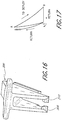
- a needle trigger 206 is formed with first and second pins 208, 210 and a gap therebetween.
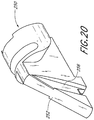
- the needle trigger is configured for cooperation with the follower member 250 shown in FIG. 20 .
- the pins 208, 210 of the needle trigger 206 initially ride along the inclined surface 252 of the follower member 250, thereby causing the follower member to move in a distal direction for extending the needles.
- FIG. 17 illustrates an exemplifying path of the pins during this cycle.
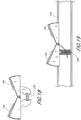
- FIGS. 18 and 19 illustrate spring mechanism 258 or 260 for biasing the arm and needle triggers back into the start position.
- the relationship between the needle trigger and the follower member may be configured such that the needles retract from the first finished position at a first rate and then retract from a second finished position at a faster rate. This may be achieved by providing a cut away portion (such as in FIG. 9 ) on the follower member.
- This retraction of the needles at a slow rate followed by a fast rate advantageously provides a "pre-tensioning" of the suture such that the needles initially tug slowly on the suture ends and then more quickly. The initial slow tugging allows the suture ends to become better aligned before withdrawal through the tissue.
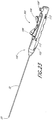
- an extrusion clamp 180 is illustrated.
- the clamp provides a transition between the handle portion 100 and the elongate body.
- the clamp includes a central lumen 182 for receiving the actuator rod and needles.
- the clamp also includes a depression for seating the needle biasing spring 154.
- the needle trigger 106A may be provided with a looped portion configured to receive the physician's thumb or finger.
- the looped portion advantageously allows the physician to pull upward on the needle trigger without relying on the biasing spring force to raise the needle trigger. This embodiment provides the physician with greater control over the movement of the needles.
- the suturing apparatus may be provided without an arm release button.
- the arm trigger could be constructed such that the initial depression moves the arm trigger into the locked position. Pressing the arm trigger again causes the arm trigger to become released and pop back up. Any release mechanism of the types known in the art may be used for this purpose.
- first and second thumb wheels may be provided along the handle portion for moving the first and second follower members.
- the interaction between the thumb wheels and the follower members preferably employs a rack and pinion system of the type known in the art. This embodiment provides the physician with even greater control over the position of the suture arms and needles.
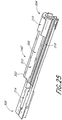
- FIGURES 23-27 illustrate an alternative embodiment of a suturing apparatus 300, wherein the release button 108 is provided along the side, rather than extending axially from the proximal end, of the main housing 102.
- the suturing apparatus 300 generally comprises an elongate body 32 and an introducer head 20 as described above, and a handle portion 100' as described further below.
- the handle portion 100' comprises a main housing 102, an arm trigger 104 and a needle trigger 106 as described above, and an arm release button 108'.
- the arm trigger, needle trigger and arm release button 108' preferably include markings to indicate the order in which the triggers are actuated, e.g., the arm trigger 104 is labeled "1,” the needle trigger 106 is labeled "2,” and the arm release button 108' is labeled "3.”
- the arm and needle triggers are preferably pivotally coupled to the main housing 102 about pin 110 such that the triggers rotate as they are depressed by the physician.
- the arm needle trigger 104 When the arm needle trigger 104 is depressed, it engages a first follower member 140' that is slidably received in the main housing 102.
- the first follower member 140' shown more particularly in FIGURES 25 and 26 , comprises an elongate body 302 having a proximal end 304 and a distal end 306 with a slot 308 extending longitudinally through the elongate body along a top side thereof.
- the elongate body 302 has a partially circular cross-section, with a proximal portion 310 of the slot receiving the arm trigger 104 when depressed.
- a proximal portion 310 of the slot receives the arm trigger 104 when depressed.
- an intermediate portion 312 of the slot is provided that partially receives the needle trigger 106 when depressed.
- a distal portion 314 of the slot is provided that partially receives the needle trigger 106 when depressed, and also receives the second follower member 150, as described further below.
- longitudinal grooves 316 are provided to receive an arm lockout wire 330, described further below.
- An inclined ramp 142' such as described above is provided within the portion 310 of the slot to engage the arm trigger 104.
- a drive wire tab 156 as illustrated also in the embodiments above is preferably secured to the distal end of the first follower member 140', such as by pins through holes 158.
- the tab 156 is secured to the actuating rod 58, which extends through the central lumen 182 of extrusion clamp 180.
- FIGURE 27 illustrates the handle 100' with the first follower member 140' removed.
- a downwardly extending leg 336 extends from a lower surface of the needle trigger 106.
- a ledge 338 on the first follower member shown in FIGURE 26 , is positioned below the leg 336, preventing the needle trigger 106 from being depressed.
- the ledge 338 also moves proximally to allow downward movement of the needle trigger 106. This prevents the needle trigger 106 from being actuated until after the arms are deployed by depressing arm trigger 104.
- the needle trigger 106 when depressed, engages a cammed surface 152 of second follower member 150, causing the second follower member 150 to compress needle biasing spring 154, as described above.
- the second follower member 150 is provided in the distal portion 314 of the slot 308 and is capable of sliding relative to the first follower member.
- Proximal of the first follower member 140' is an arm spring 144
- proximal of arm spring 144 is third follower member 320, which has an inclined surface 322 which engages arm release button 108'.
- Third follower member has longitudinal grooves 324 on both sides thereof to receive the arm lockout wire 330 described below.
- Elongate member 108A' extends distally from the third follower member 320 underneath the arm spring 144.
- an arm lockout wire 330 extends proximally from the one side of the second follower member 150, through the longitudinal groove 316 on one side of the elongate body 302 of the first follower member 140', through the longitudinal groove 324 on one side of the third follower member 320, around the proximal end of the third follower member, and back through the grooves 324 and 316 on the opposite side of the housing and connecting with the second follower member 150.
- arm lockout wire 330 also moves distally, and becomes positioned underneath the arm release button 108'. This prevents the arm release button 108' from being depressed while the needles are being actuated, until the second follower member returns to its initial position.
- the main housing of the handle portion 100' includes a safety opening or window 112 as described above for manually retracting the needles.
- the main housing also includes a safety opening or window 113 for manually retracting the arms.
- the opening 112 cooperates with the opening 332 in second follower member 150, allowing for a pin to be inserted into the openings to manually bring the second follower member back to its initial configuration.
- the opening 113 cooperates with the opening 334 in the first follower member 140' for the same purpose.
- Operation of the suturing assembly 300 as illustrated in FIGURES 23-27 first begins, after appropriate placement of the assembly, by depressing arm trigger 104 labeled "1".
- Depressing arm trigger 104 causes the first follower member 140' to move proximally within the housing 102, compressing arm spring 144 and moving actuating rod 58 to deploy the arms 24, 24' described above.
- Arm trigger 104 preferably can be depressed until it is secured or locked in a down position, such as described with the embodiment of FIGURE 7 above.
- depressing needle trigger 106 labeled "2" causes the second follower member 150 to slide distally within the slot of first follower member 140', compressing the needle biasing spring 154 and causing needles 70 and 70' to splay outward from the elongated body 32.
- the needle trigger 106 may be configured such as described with respect to FIGURE 16 above. More particularly, the needle trigger 106 may have pins 208, 210 that ride initially along an inclined surface of the second follower member 150, thereby causing the follower member to move in a distal direction for extending the needles.
- the pins extend beyond the bottom edge of the inclined surface, thereby relieving the force on the follower member and allowing the follower member to snap back in a proximal direction. This occurs while maintaining the needle trigger in the fully depressed condition. Accordingly, the needles are first fully extended and then automatically snap back when the needle trigger reaches a first finished position (i.e., is fully depressed).
- the needle trigger may remain in its depressed configuration after the second follower member 150 snaps back to its original configuration, or the needle trigger may automatically return to its initial configuration. If the needle trigger 106 does not automatically return to its initial configuration, the operator may simply pull the needle trigger upward along the body of the second follower member, spreading the gap between the pins 208, 210 until the pins are once again above the inclined surface.
- the operator presses down on the arm release button 108', labeled "3". This causes the third follower member 320 to move distally, and causes the elongate member 108A' to contact a corner portion of the arm trigger 104 and urge the arm trigger distally so that it is released from the first follower member 140'.
Landscapes
- Health & Medical Sciences (AREA)
- Surgery (AREA)
- Life Sciences & Earth Sciences (AREA)
- Biomedical Technology (AREA)
- Nuclear Medicine, Radiotherapy & Molecular Imaging (AREA)
- Engineering & Computer Science (AREA)
- Heart & Thoracic Surgery (AREA)
- Medical Informatics (AREA)
- Molecular Biology (AREA)
- Animal Behavior & Ethology (AREA)
- General Health & Medical Sciences (AREA)
- Public Health (AREA)
- Veterinary Medicine (AREA)
- Cardiology (AREA)
- Surgical Instruments (AREA)
Description
- The invention relates generally to a suturing apparatus, such as for applying suture within biological tissue that may not be directly accessible to the physician.
- Physicians frequently use suture to close cuts, punctures, incisions and other openings in various biological tissue, such as blood vessels, of the human body.
- In an arterial catheterization procedure, a relatively small percutaneous incision is made in the femoral or other artery. A catheter is inserted through the incision and directed along an arterial path to a target area, such as the heart, to perform one or more procedures, such as an angioplasty or angiogram. These procedures are intended to be relatively quick 'outpatient' procedures.
- Upon completion of the catheterization procedure, the physician typically creates a 'thrombus patch' by applying direct pressure to the patient's thigh to make the blood around the incision clot. It is very important that the applied pressure does not impede the flow of blood through the femoral artery. As a result, it is commonplace for the physician to apply direct pressure by hand for the first twenty minutes after the procedure. During this time, the physician can feel the pulse to assure the artery is not occluded. Afterwards, the physician typically transfers responsibility to an assistant who then applies direct pressure using sandbags, clamps or other devices. A significant problem with this approach is that it is frequently necessary to apply the pressure for an extended period of time, such as twenty-four hours or longer.
- Another problem with the thrombus patch method is that the high blood pressure in the artery can cause the thrombus patch to rupture or burst while direct pressure is being applied to the thigh or after direct pressure is removed. This requires the entire process to be reinitiated. If the patch ruptures and is not quickly restored, substantial bleeding can occur, with potentially fatal consequences. Because thrombus patches frequently burst, the patient is often kept in the hospital or catheterization lab overnight for observation. As a result, these 'out-patient' procedures become 'in-patient' procedures, simply because a thrombus patch is often unreliable and/or difficult to create. Staying in the hospital increases patient discomfort and hospital expenses, which are often disproportionate to the actual medical procedure performed.
- Furthermore, if a thrombus patch cannot be adequately formed, the physician may need to anesthetize the patient and occlude the blood flow to the artery. At this point, the physician is required to make a large incision in the thigh to allow conventional suturing with a needle, suture the artery with conventional means, restore blood flow to the artery, and suture the incision in the thigh. This results in additional discomfort and expenses for the patient.
- While the above problems could potentially be avoided by suturing the blood vessel immediately following the catheterization procedure, the size and location of the artery make suturing extremely difficult. More specifically, the opening in the thigh is often too small and too deep to provide enough working space for suturing the artery using conventional methods. Thus, in order to suture the vessel using conventional methods, the opening in the thigh would have to be significantly enlarged, thereby further increasing the recovery period and exposing the patient to additional discomfort, undesirable scarring, possible infection and other health risks.
-
US 6,562,052 B2 relates to a suturing device and method that allows a physician to remotely suture biological tissue. The device includes an elongate body, first and second arms operably connected to the elongated body, whereby each arm mounts an end portion of a suture, and first and second needles, each needle having a distal end and being mounted such that the distal end of the needle is movable to engage respective end portions of said suture. The suturing apparatus further includes an actuator which drives the needles to engage the suture non-simultaneously. The two -part form of independent claim 1 is based on this document.EP 0 870 486 A1 relates to apparatus to remove tissue. The apparatus has an outer cannula and an inner cannula received within the outer cannula. The cannula are longitudinally movable relative to each other. There is an abutment at the end of one cannula to contact the other cannula. A drive permits advancing of the other cannula to contact the abutment whereby tissue between the other cannula and the abutment is removed. -
US 2004/0068273 A1 relates to an incision closing apparatus for simultaneous insertion of suture needles through adjacent sides of an incision in a fascia layer within a patient. An insertion end is sized for insertion through the incision and a shield is retractably extended from the insertion end positioned interior of the fascia layer. A plurality of elongated spokes having needles thereon are extended from openings within the insertion end for ejection of needles having attached suture filaments through adjacent sides of the fascia layer incision. -
WO 2004/112618 A3 relates to a surgical stapling device which includes a handle portion, a central body portion and a SULU. The SULU includes a proximal body portion, an intermediate pivot member and a tool assembly. -
EP 0 656 191 A2 relates to a surgical clip applier comprising a housing, a pair of handles pivotally connected to opposite sides of the housing, and a jaw blade assembly fixedly connected to the housing. The jaw blade assembly includes a pair of jaws for receiving and deforming a clip therebetween and a clip carrier for supplying a series of clips to the jaws. - Aspects of the invention are set out in the claims.
-
-
FIGURE 1 illustrates one embodiment of a suturing apparatus and related assembly in an exemplifying use environment. -
FIGURE 2 illustrates an enlarged cross-sectional view of the suturing apparatus in an exemplifying use environment, such as a patient's thigh. -
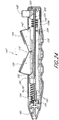
FIGURE 3 is a perspective view of the suturing apparatus formed with an improved handle portion. -
FIGURE 3A is a perspective view of an arm trigger, which forms a portion of the handle portion of the suturing apparatus ofFIGURE 3 . -
FIGURE 3B is a perspective view of a needle trigger, which forms a portion of the handle portion of the suturing apparatus ofFIGURE 3 . -
FIGURE 4 is a side partial cross-sectional view of the handle portion wherein the arm trigger and needle trigger are in the non-depressed positions. -
FIGURE 5 is a side partial cross-sectional view of the handle portion wherein the arm trigger is fully depressed for locking the suture arms in the deployed condition. -
FIGURE 6 is a side partial cross-sectional view of the handle portion wherein both the arm trigger and the needle trigger are fully depressed for extending the needles to engage the suture ends held by the suture arms. -
FIGURE 6A is a side view illustrating the relationship between the needle trigger and the second follower member in the handle portion. -
FIGURE 6B is a perspective view of the second follower member. -
FIGURE 7 is a perspective view illustrating a preferred comer portion of the arm trigger wherein the corner portion is provided with a camming surface. -
FIGURE 8 is a side view illustrating a preferred embodiment of a release button for releasing the arm trigger and thereby retracting the suture arms. -
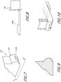
FIGURE 9 is a side view illustrating an alternative embodiment of a corner portion of the arm trigger wherein a section is cut away to facilitate the release of the arm trigger. -
FIGURE 10 is another perspective view illustrating a preferred corner portion of the arm trigger wherein the corner portion is provided with a camming surface. -
FIGURE 11A is an enlarged perspective view of the distal end portion of the suturing apparatus ofFIGURE 3 . -
FIGURE 11B is perspective view of the distal end portion ofFIGURE 11A with a pair of suture arms partially deployed. -
FIGURE 11C is a rear perspective view of the distal end portion ofFIGURE 11A with a pair of suture arms partially deployed. -
FIGURE 12A is a perspective view of a suture end having a flattened distal portion with an eyelet. -
FIGURE 12B is a perspective view of distal and proximal ends of a suture each having a flattened distal portion with an eyelet. -
FIGURE 13 is a cross-sectional view of the suturing apparatus ofFIGURE 3 with the distal end portion inserted through an arterial wall. -
FIGURE 14 is a cross-sectional view of the suturing apparatus ofFIGURE 3 with the distal end portion inserted through an arterial wall and a pair of suture arms partially deployed. -
FIGURE 15 is a cross-sectional view of the suturing apparatus ofFIGURE 3 with a pair of suture arms fully deployed and a pair of needles engaging the suture arms. -
FIGURE 16 is a perspective view illustrating an alternative embodiment of a needle trigger wherein the camming surface is provided by a pair of opposing pins with a gap therebetween. -
FIGURE 17 illustrates an exemplifying path of the camming surface ofFIGURE 16 during deployment and automatic retraction of the needles. -
FIGURE 18 is a side view illustrating an alternative configuration of the arm trigger and needle trigger wherein a compression spring is provided for biasing the triggers into the non-depressed positions. -
FIGURE 19 is a side view illustrating another alternative configuration of the arm trigger and needle trigger having a compression spring in a different location. -
FIGURE 20 is a perspective view illustrating an alternative embodiment of a follower member configured for engagement with the needle trigger ofFIGURE 16 , wherein the follower member is provided with an inclined surface and a return slot for guiding the opposing pins back to the starting position. -
FIGURE 21 is a perspective view illustrating an extrusion clamp for securing the elongate body to the handle portion. -
FIGURE 22 is a perspective view illustrating an alternative embodiment of a suturing apparatus having an improved handle portion wherein the needle trigger includes a looped portion. -
FIGURE 23 is a perspective view illustrating another embodiment of a suturing apparatus. -
FIGURE 24 is a side view of the handle of the suturing apparatus ofFIGURE 23 , with a portion of a housing of the handle removed. -
FIGURE 25 is a perspective view of the first follower removed from the housing ofFIGURE 24 . -
FIGURE 26 is a perspective view of the first follower member ofFIGURE 25 from above. -
FIGURE 27 is a perspective view of the handle of the suturing apparatus ofFIGURE 23 , with the first follower removed. - The preferred embodiments of the present invention described below relate particularly to closing incisions within biological tissue. While the description sets forth various embodiments and specific details, it will be appreciated that the description is illustrative only and should not to be construed in any way as limiting the invention. Furthermore, various applications of the invention, and modifications thereof, which may occur to those skilled in the art, are also encompassed by the general concepts described below.
- With reference now to
FIGURE 1 , one preferred assembly 4 for closing an incision is illustrated in an exemplifying use environment. The assembly 4 generally comprises asuturing apparatus 6 and a catheter sheath introducer (CSI) 8. Thesuturing apparatus 6 may be used to seal a blood vessel following an interventional catheterization procedure, such as an angiogram, angioplasty or other procedure. With reference now toFIGURE 2 , an enlarged view of the treatment site is illustrated. In this view it can be seen that a physician makes aninitial incision 10 in anupper thigh region 12 of apatient 2. The physician then inserts a needle (not shown) into theincision 10 such that the needle pierces afemoral artery 14, creating avessel incision 16 therein. When blood bleeds back from the insertion, the physician knows the needle has entered thefemoral artery 14. The physician then inserts a guidewire (not shown) through the needle and into theartery 14. The physician may take the needle out and insert a plastic needle (not shown) over the guidewire once the guidewire is in place. The guidewire may then be taken out. - With the plastic needle in place, the physician can insert the
CSI 8. TheCSI 8 is typically a single-lumen catheter with a valve located on its proximal end. The valve is configured to prevent extraneous bleed back and/or to introduce medication into the patient's body. Thevessel incision 16 provides access for medical instruments and probes inside thearterial vessel 14. An instrument, such as a therapy catheter, may be advanced through theartery 14 via theCSI 8 to perform a procedure within the body. - After the medical procedure has been completed and the instrument (e.g., therapy catheter) has been removed, the physician inserts the
suturing apparatus 6 through theCSI 8 such that asuture introducer head 20, distally attached to a hollowelongate body 32, enters thefirst incision 10, passes through thetissue 18 of the patient'sthigh 12, and enters thefemoral artery 14 through thevessel incision 16. At this point, thesuture arms 24, 24' are deployed and theintroducer head 20 of the suturing apparatus is pulled back such that the suture arms contact theinner wall 22 of thefemoral artery 14. As described in more detail below, needles are deployed from the introducer head which penetrate thewall 14 of thefemoral artery 14 adjacent theincision 16. The needles capture suture ends from the suture arms and the needles are then retracted to withdraw the suture ends back through the wall of the femoral artery. The arms are then retracted and the entire suturing apparatus is withdrawn such that the suture ends may be tied together to close the incision. - With reference now to
FIGURE 3 , a preferred embodiment of thesuturing apparatus 6 will be described in more detail. Additional details and exemplary methods of operation are described in Applicant'sU.S. Pat. Nos. 6,245,079 and6,562,052 . It will be appreciated that although thedevice 6 is preferably used for suturingvessel walls 22, thedevice 6 can be used to suture other tissues such as, by way of example, a patent ductus arteriosus, a patent foramen ovale (PFO), a heart defect, a puncture wound, and the like. - In the embodiment illustrated in
FIG. 3 , thesuturing apparatus 6 generally comprises anelongate body 32, anintroducer head 20 and ahandle portion 100. Thehandle portion 100 allows the physician to operate the suturing apparatus such that suture may be applied to an incision in a very quick and easy manner. The handle portion requires very little manipulation during use and may be operated with a single hand if necessary. The suturing apparatus may be used to close an incision located deep within the patient's tissue (e.g., in the femoral artery) without requiring the application of pressure over an extended period of time. As a result, the suturing apparatus may substantially reduce the recovery period following a medical procedure, thereby allowing the patient to return home more quickly and substantially reducing costs. The dimensions of thesuturing apparatus 6 may vary according to the suture site and the biological tissue intended to be sutured. In one configuration, thesuture introducer head 20 has a diameter of about 0.27 cm (0.105 inches), and the hollowelongate body 32 has a diameter of about 0.25 cm (0.098 inches). - The
handle portion 100 comprises amain housing 102, anarm trigger 104, aneedle trigger 106 and anarm release button 108. The arm and needle triggers provide actuators for producing movement of internal components within the main housing, which in turn move at least one arm and needle for applying suture to a treatment site. As will be described in more detail below, the handle portion is constructed such that thearm trigger 104,needle trigger 106 andarm release button 108 may be depressed by the physician in a particular order to extend and retract cooperating suture arms and needles along theintroducer head 20 for applying suture to an incision. - The arm and needle triggers are preferably pivotally coupled to the
main housing 102 aboutpin 110 such that the triggers rotate as they are depressed by the physician. As will be described in more detail below, the pivotal rotation facilitates the cam-like interaction of the triggers with the internal components of the main housing. Anopening 112 is provided along themain housing 102 for allowing manual retraction of the needles in the event that the needles become stuck in the tissue during retraction. This provides a safety mechanism to ensure that the needles of the suturing apparatus cannot become stuck in the extended position. In one embodiment, a tool (not shown) is inserted through theopening 112 in themain housing 102 for applying force to assist in the retraction of the needles. - With reference to
FIGURE 3A , thearm trigger 104 is shown in isolation.Loops pin 110 in the main housing. Thebottom corner portion 120 along the proximal end portion of the arm trigger is shaped with a protrusion 120A which provides a camming surface for engaging a first slidable follower member in the main housing. The protrusion also allows the arm trigger to be held in the depressed position for locking the arms in the deployed condition. Thetop surface 118 of the arm trigger is shaped for engagement with the physician's thumb or finger. - With reference to
FIGURE 3B , theneedle trigger 106 is shown in isolation.Loop 122 is provided along the proximal end of the needle trigger for receiving thepin 110 in the main housing. The loop is shaped to fit within the gap between theloops FIGURE 3A ). Thebottom corner portion 130 along the distal end portion of the needle trigger provides a camming surface for engagement with a second slidable follower member in the main housing. Thetop surface 128 of the needle trigger is shaped for engagement with the physician's thumb or finger. - Preferred internal components of the
handle portion 100 will now be described in more detail. The internal components cooperate with the arm and needle triggers 104, 106 (i.e., actuators) andarm release button 108 for effecting movement of the arms and needles during the application of suture. More specifically, the arm and needle triggers actuate the arms and needles by effecting movement of the internal components contained with the main housing. As described above, the arm and needle triggers each preferably havecorner portions - With reference now to
FIGURE 4 , a cross-sectional side view of thehandle portion 100 is shown for purposes of illustration. It can be seen that afirst follower member 140 is slidably disposed within the interior of themain housing 102. Thefirst follower member 140 is connected to a proximal end of an actuating rod, preferably through adrive wire tab 156 described below, which extends distally through the main housing and elongate body for connection to each of the arms. When thefirst follower member 140 is in the distal position, as shown inFIGURE 4 , the arms are fully contained within the introducer head. However, when thefirst follower member 140 is moved proximally by the arm trigger 104 (indicated by the arrow inFIGURE 5 ), each of the arms deploys outward through apertures on the sides of the introducer head. (The operation of the arms and needles will be described in more detail below.) Accordingly, longitudinal movement of thefirst follower member 140 relative to the main housing controls the position of the arms. Anarm spring 144 provides a biasing force to maintain thefirst follower member 140 in the distal position in the absence of any external input. Although one type of arm spring is shown for purposes of illustration, any known biasing mechanisms may be used for maintaining thefirst follower member 140 into the distal position. - It can be seen that the
first follower member 140 is formed with an inclined "cammed"surface 142 along a distal face. As shown inFIGURE 4 , the inclined cammed surface is configured for engagement with the camming surface along thecorner portion 120 of thearm trigger 104. When thearm trigger 104 is depressed, thecorner portion 120 of thearm trigger 104 pushes along theinclined surface 142 of thefirst follower member 140. The downward force acting on the inclined surface results in longitudinal translation of the first follower member. The longitudinal force causes the first follower member to slide in a proximal direction (i.e., backward) within the main housing. As the first follower member slides backward, the actuating rod is pulled in a proximal direction, thereby causing the arms to deploy outward through the ports. - The
arm trigger 104 is preferably releasably securable in the fully depressed condition for locking the arms in the deployed condition. As a result, it is not necessary for the physician to apply a constant a force on thearm trigger 104 to maintain the suture arms in the deployed condition. As described above, thecorner portion 120 of the arm trigger is preferably formed with a protrusion 120A.FIGURE 7 provides an enlarged view of thecorner portion 120 including the protrusion 120A. The protrusion is shaped to be captured and held beneath thefirst follower member 140 when thearm trigger 104 is fully depressed. As discussed above, thearm spring 144 urges the first follower member forward (in the distal direction) such that the first follower member abuts the arm trigger and securely holds the protrusion. Accordingly, the cooperation of the protrusion and the first follower member creates a detent mechanism such that the arm trigger is selectively maintained in the depressed position.FIGURE 10 provides another perspective view of the corner portion of the arm trigger. - With reference again to
FIGURE 4 , thearm release button 108 is configured for releasing the protrusion when it is desired to retract the deployable arms. As illustrated, thearm release button 108 is preferably provided along a proximal end of themain housing 102 and is configured for engagement with thearm trigger 104. Anarm release spring 144 may be provided for maintaining thearm release button 108 in the non-depressed condition in the absence of an external input. Accordingly, the arm release button can only act on the arm trigger when a sufficient force is applied to overcome the biasing force of thearm biasing spring 144. With reference now toFIGURE 8 , thearm release button 108 is shown in isolation. The arm release button is provided with an elongate member 108A that is configured to contact the corner portion of the arm trigger when the arm trigger is being held in the fully depressed condition. More particularly, the elongate member 108A is configured to urge the arm trigger in the distal direction such that the protrusion is released from the first follower member.FIGURE 9 is a cross-sectional view illustrating an alternative arm trigger wherein a section of the corner portion has been cut away to facilitate the release of the arm trigger upon actuation of the arm release button. It will be appreciated that alternative methods may be used to release the arm trigger. For example, the arm trigger may be provided with a lip on its upper surface and an actuator may be used to engage the lip to pull the arm trigger back to its initial position. - A
second follower member 150 is slidably disposed within the interior of the main housing at a location distal to thefirst follower member 140. Thesecond follower member 150 is connected to the proximal ends of the elongate needles 70, 70'. Thus, longitudinal movement of thesecond follower member 150 relative to themain housing 102 effects the position of the needles. Thesecond follower member 150 has a proximal position - (as shown in
FIGURES 4 and5 ) wherein the needles are in the retracted (non-deployed condition). Aneedle biasing spring 154 engages the second follower member for maintaining the second follower member in the proximal position in the absence of any external input. Although one particular embodiment of aneedle biasing spring 154 is shown for purposes of illustration, a wide variety of different biasing mechanisms may be used for biasing the second follower member into the proximal position. - The
second follower member 150 is provided with an inclined "cammed"surface 152 along the proximal face such that the second follower member cooperates with a camming surface along thecorner portion 130 of theneedle trigger 106 in a manner substantially similar to that of the first follower member. More particularly, as shown inFIGURE 5 , the inclined surface is shaped for slidable engagement with a camming surface of theneedle trigger 106. - As the
needle trigger 106 is depressed, the camming surface along thecorner portion 130 of the needle trigger pushes against theinclined surface 152 of thesecond follower member 150, as illustrated in the cross-sectional view ofFIGURE 6A . The force from the needle trigger creates a resulting longitudinal force on the second follower member that causes the second follower member to slide distally relative to the main housing. As the second follower member translates distally within the housing (as denoted by the arrow inFIGURE 6A ), theneedles 70, 70' are pushed in a distal direction, thereby causing the distal end portions of the needles to extend outward from the introducer head for engagement with the suture arms. The extension of the needles from the introducer head will be described in more detail below. In preferred embodiments, thesecond follower member 150 is contained within a body portion that is integral with the first follower member. The body portion provides a slotted track such that the second follower member may be guided proximally and distally during use. Thus, the first and second follower members are preferably slidably coupled to each other. It should also be noted that the second follower member may be formed with a longitudinal lumen for slidably receiving the actuatingrod 58. Accordingly, the actuatingrod 58 may be slid longitudinally by movement of the first follower member without interfering with the second follower member.FIGURE 6B provides a perspective view of thesecond follower member 150 having aninclined surface 152. It can be seen that the lower portion of the second follower member is thinner in construction. The thinner section is configured to fit within a groove in the body portion for guiding the movement of the second follower member, as described above. The second follower member is also formed with aslot 160 for receiving a tool through thewindow 112 in the main housing 102 (FIGURE 3 ). The tool may be inserted through the window and into the slot. The tool may then be used to slide the second follower member in the event that it sticks, thereby providing a safety mechanism as described above. - The cammed surface of the first and second follower members is shaped to produce a desired motion in response to actuation of the arm and needle triggers, respectively. In one preferred embodiment, at least a portion the cammed surface of the second follower member is inclined at about 35° or more relative to the longitudinal axis. The angle of inclination is denoted by the symbol α (alpha) in
FIGURE 6A . In another embodiment, at least a portion of the cammed surface is inclined at about 40° or more relative to the axis. In another variation, at least a portion of the cammed surface is inclined at about 41° relative to the axis. In another variation, at least a portion of the cammed surface is inclined at between about 35-45° relative to the axis. In another variation, at least a portion of the cammed surface is inclined at between about 39-43° relative to the axis. In another variation, at least a portion of the cammed surface is inclined at between about 40-42° relative to the axis. In still another variation, the camming surface is curved. The same preferred ranges also apply to the cammed surface of the first follower member. It will be appreciated that the ratio of trigger movement to needle movement is proportional to the angle of the inclined surface. It has been found that the above angles provide excellent performance while minimizing the diameter of the handle portion. For example, a lower angle would make the follower members more difficult to move due to frictional forces. On the other hand, a higher angle would necessitate a larger follower member in order to produce the same amount of longitudinal translation, thereby necessitating a larger (e.g., larger diameter) handle portion. Furthermore, it has been found that an inclined surface formed with a substantially constant angle provides a substantially directly proportional relationship between trigger movement and needle movement. As a result, the physician is able to advance and retract the needles with great precision and predictability by controlling the movement of the needle trigger. - With reference again to
FIGURES 4 through 6 , themain housing 102 is preferably constructed of a translucent or transparent material, such as plastic, such that the movement of the components within the main housing is visible to the physician. The transparency advantageously provides visual feedback to the physician regarding operation of the suturing apparatus. If desired, markings or other indicia may be provided such that the position of the needles may be easily perceived during use. Alternatively, a window may be provided for observing the movement of the internal components or a portion of one or more internal components may extend through the main housing to an exterior surface for purposes of visibility. - With reference to
FIGURES 11A through 11C , the distal end portion of the suturing apparatus will now be described in more detail. The illustrated distal end portion provides one preferred suturing apparatus that may be operated using the improved handle portion described above. As shown, the distal end portion comprises thesuture introducer head 20, a pair ofsuture arms 24, 24', a pair of suture clasps 56, 56', a pair ofsuture arm apertures 50, 50', a pair of curved or slanted needle guides 48, 48', a pair ofneedle apertures 30, 30', adistal end 54, ahole 46, asuture 52 and anactuating rod 58. The distal end portion further comprises a pair ofneedles 70, 70' (seeFIGURES 13 through 15 ). When thesuture arms 24, 24' are retracted into thesuture arm apertures 50, 50' and theneedles 70, 70' are retracted into theneedle apertures 30, 30', thearms 24, 24' and theneedles 70, 70' are recessed within thesuture introducer head 20, as shown inFIGURE 11A . This prevents thearms 24, 24' and theneedles 70, 70' from causing tissue damage while the distal end portion passes through a biological structure. -
FIGURES 11B and 11C illustrate the distal end portion of the device 6 (FIGURE 3 ) with thesuture arms 24, 24' partially deployed outwardly from their recessed positions. Such deployment is achieved by partially depressing thearm trigger 104, as described above with reference toFIGURES 4 through 6 . Depressing thearm trigger 104 translates the first follower member 140 (FIGURE 4 ) andactuating rod 58 proximally, which brings thesuture arms 24, 24' into contact with a pair of proximalinside edges 78, 78' of thesuture arm apertures 50, 50'. As the arm trigger is depressed further, the proximalinside edges 78, 78' force thesuture arms 24, 24' into a deployed state. In one suturing apparatus, thesuture arms 24, 24' continue to deploy radially until thearms 24, 24' are substantially parallel with each other and substantially perpendicular to the longitudinal axis of thesuture introducer head 20, as shown inFIGURE 15 . In other suturing apparatus, thesuture arms 24, 24' may be "fully" deployed when they reach an acute or obtuse angle relative to each other. - As shown most clearly in
FIGURE 11B , each of thesuture arms 24, 24' comprises asuture clasp 56, 56' which holds an end of thesuture 52. Each of thesuture arms 24, 24' are pre-loaded with the ends of thesuture 52 before operation. The ends of thesuture 52 then pass from the suture clasps 56, 56' to thehole 46 whereby the ends of thesuture 52 enter thesuture introducer head 20 and are passed proximally through the hollowelongate body 32. In the embodiment illustrated inFIGURE 11B , each end of thesuture 52 has a capture portion comprising a loop which is tied onto the ends of the suture claps 56, 56'. It is contemplated, however, that the capture portions are not restricted solely to tied loops, rather other types of capture portions may be utilized such as, by way of example, spheres or ferrules. -
FIGURE 12A illustrates another configuration of a capture portion wherein the end of thesuture 52 comprises a flatteneddistal region 93 having a hole oreyelet 95. In the configuration illustrated inFIGURE 12A , thesuture 52 comprises astrand 91 of deformable material that is preferably monofilament, such as Deklene (from Genzyme), Prolene (from Johnson & Johnson), or Nylon (from Johnson & Johnson). In one configuration, thestrand 91 is advantageously approximately 0.0254 cm (0.010") thick and has a length that makes it suitable for use in suture procedures. - In the formation of the flattened
distal portion 93, the distal end of thestrand 91 is heated until the distal end melts or is otherwise plastically or thermally deformed to form a locally deformed region (such as a globule) that is broader than the rest of thestrand 91 in at least one dimension (i.e., at least one dimension of thestrand 91 has been increased). Once the deformed region is formed, thestrand 91 may be allowed to cool, and the deformed region may then be flattened by use of a die. The die preferably has a relief or recessed portion for accepting thestrand 91 and the deformed region. A block, which preferably also has a recessed portion that mates with the recessed portion, may then be placed over the deformed region. The deformed region is then squeezed between the die and the block, resulting in the formation of the flatteneddistal portion 93 illustrated inFIGURE 12A . The flatteneddistal portion 93 preferably has a thickness that matches the rest of thestrand 91. The edges of the flatteneddistal portion 93 may then be trimmed to form a smooth disc portion to reduce the risk of such edges snagging on vessel walls during suturing procedures. - As illustrated in
FIGURE 12A , theeyelet 95 is formed within the flatteneddistal portion 93. A punch (not shown) such as a hypotube may be used to poke through the flatteneddistal portion 93, thereby leaving theeyelet 95 within the flatteneddistal portion 93. Theeyelet 95 is formed such that a surgical hook or needle may pass through theeyelet 95 in a suturing procedure. The flatteneddistal portion 93 acts as a connector to the hook or needle, allowing thestrand 91 to be picked up by the hook or needle. The method of forming theeyelet 95 described herein, including the forming of the flatteneddistal portion 93, advantageously results in no significant reduction in the mechanical strength of thestrand 91, with the material throughout the strand 91 (including the material in the flattened distal portion 93) having substantially uniform mechanical strength. Methods for forming the flatteneddistal region 93 are discussed in greater detail in Applicant's above-mentionedU.S. Patent No. 6,562,052 , entitled SUTURING DEVICE AND METHOD. - Advantageously, the suture embodiment shown in
FIGURE 12A has no knots or ties formed therein which might increase the profile of thesuture strand 91 or make it easier for thesuture 52 to snag during use. This process may advantageously be repeated at the proximal end of thestrand 91, resulting ineyelets 95, 95' at both ends of thestrand 91, as illustrated inFIGURE 12B . The flatteneddistal portion 93 at one or more of the ends of thestrand 91 may be bent (not shown) at an angle with respect to the rest of thestrand 91 to facilitate the guiding of a surgical needle through theeyelet 95. -
FIGURE 11C illustrates one preferred configuration of the hollowelongate body 32 which comprises five lumens. Two of thelumens 60, 60' are used to house theneedles 70, 70'. Once thesuture arms 24, 24' have been deployed, as discussed with reference toFIGURES 11B and 11C (and in greater detail below), the needle trigger 106 (FIGURE 3 ) can be depressed to advance theneedles 70, 70' from a recessed position within thesuture introducer head 20 to a distally extended position (seeFIGURE 15 ). In one suturing apparatus, theneedles 70, 70' move distally at substantially the same time. In another suturing apparatus, theneedles 70, 70' may be actuated separately such that one of theneedles 70, 70' advances before the other. - When the two
needles 70, 70' move distally, the needle guides 48, 48' direct theneedles 70, 70' out of theneedle apertures 30, 30' at an angle relative to the longitudinal axis of thesuture introducer head 20, as illustrated inFIG. 15 . Theneedles 70, 70' are flexible and preferably made of a material with shape memory, such as SUPERFLEX NITINOL™. Alternatively, theneedles 70, 70' may be comprised of spring steel, surgical stainless steel or any variation thereof. Each of theneedles 70, 70' preferably has a diameter of about 0.05 cm (0.019 inches), but needles with other diameters may be used in accordance with the particular medical procedure contemplated. - When the
needles 70, 70' advance distally, as discussed above, the needle guides 48, 48' cause theneedles 70, 70' to bend radially outward. As shown most clearly inFIG. 15 , a further outward, radial bend preferably is imparted to theneedles 70, 70' when they come into contact with a pair ofangled surfaces 57, 57' of thesuture arms 24, 24'. When theneedles 70, 70' are retracted into theneedle lumens 60, 60', theneedles 70, 70' resume a straight configuration as a result of their resiliency. Although the suturing apparatus ofFIGS. 11A through 15 preferably comprisesflexible needles 70, 70', which bend during deployment, it is contemplated that other configurations may advantageously comprise rigid needles which may be permanently straight or curved. - Referring again to
FIG. 11C , the hollowelongate body 32 contains acentral lumen 64 which is used to house the actuatingrod 58. Anotherlumen 62 is used to house the length of thesuture 52 to prevent thesuture 52 from becoming tangled. Alternatively, thesuture 52 may be passed through thecentral lumen 64 along with the actuatingrod 58. - A fifth lumen 62' is preferably used for "bleed back," which enables the physician to determine whether the
distal end 54 of thesuture introducer head 20 is positioned within theartery 14. Bleed back is accomplished through thehole 46 at thedistal end 54 of thesuture introducer head 20, thesuture arm apertures 50, 50' and any other openings in thesuture introducer head 20. The direction of blood flow for bleed back is indicated by three dashed arrows inFIG. 13 . If thedistal end 54 of thesuture introducer head 20 is positioned within theartery 14, blood pressure due to blood entering into thehole 46 will be much greater than if thedistal end 54 is not within theartery 14. In one embodiment, the lumen 62' extends to a port (not shown) at a proximal portion of thedevice 6, whereby the physician can determine the blood pressure within the bleed back lumen 62' by monitoring blood flow from the port. For example, the lumen 62' may be attached to a balloon which inflates when thedistal end 54 of thesuture introducer head 20 passes into theblood vessel 14. In another embodiment, a pressure sensor may be coupled with the lumen 62' to provide the physician with a numeric blood pressure reading. Alternatively, the lumen 62' may be used to inject medication or for diagnostic purposes. - In a preferred embodiment, two thin stripes 66 (only one shown in
FIGURE 11C ) marked on the exterior of the hollowelongate body 32 extend along the entire length of the hollowelongate body 32. Thestripes 66 provide a visual indication of the circumferential location of theneedles 70, 70' relative to the hollowelongate body 32. Thestripes 66 facilitate aligning theneedles 70, 70' with the axis of theblood vessel 14, so that needle incisions 80, 80' (seeFIGURE 15 ) formed in thevessel wall 22 by theneedles 70, 70' will be aligned along a dimension transverse to the flow of blood within theartery 14. This enables the physician to place thesuture 52 within thevessel wall 22 such that thesuture 52 closes theincision 16 transversely to the blood flow. This is the most efficient direction to close theincision 16. Proper insertion of theneedles 70, 70' reduces the risk of damage to thevessel wall 22. Alternatively, the hollowelongate body 32 may have only onestripe 66 which denotes the circumferential location of one of the twoneedles 70, 70'. Because theneedles 70, 70' deploy from opposite sides of thesuture introducer head 20, knowledge of the location of one needle provides the physician with knowledge of the location of the other needle. - As illustrated in
FIGURE 11C , the exterior surface of the hollowelongate body 32 includes amarker 68 which denotes a proximal position to which theCSI 8 should be partially withdrawn (after the distal portion 26 of thesuturing apparatus 6 has been inserted into the blood vessel 14) to expose theneedle apertures 30, 30'. The partial withdrawal of theCSI 8 is discussed in detail in Applicant's above-mentionedU.S. Patent No. 6,562,052 , entitled SUTURING DEVICE AND METHOD. Themarker 68 is shown as a visual marker, but may additionally or alternatively be in the form of a ridge, groove, or other physical structure which interacts with a corresponding structure of theCSI 8 to allow the physician to position theCSI 8 using a sense of feel. For example, theCSI 8 and the hollowelongate body 32 could be configured to releasably engage or interlock with one another when theCSI 8 reaches a predetermined position along theelongate body 32. It is contemplated that a specially formedCSI 8 comprises such an interlocking structure, and is included within the scope of the invention. It is further contemplated that one or more additional markers (not shown) may advantageously be provided along the length of the hollowelongate body 32, distal to themarker 68, to indicate other positions of theCSI 8 relative to theelongate body 32, such as the position at which thesuture arms 24, 24' are exposed outside theCSI 8. - The use and operation of the suturing apparatus will now be described with reference to
FIGURE 3 through 15 . From the following description, it will be understood that thehandle portion 100 provides an improved mechanism for quickly and easily actuating the components of the suturing apparatus to apply suture to an incision, such as to close a vessel wall after a surgical procedure. - Before the procedure, the
suture arms 24, 24' are pre-loaded with the ends of a suture, such as, for example, a polypropylene suture. Specifically, each end of a suture has a capture portion comprised of a loop, a sphere or a ferrule. The loop, sphere or ferrule may be formed (e.g., by heat molding) with the same suture material as the length of suture. Alternatively, the loop, sphere or ferrule may be a separate piece attached (e.g., molded, glued, etc.) onto each end of the length of suture. The loop, sphere or ferrule is loaded in respective suture end supports of thearms 24, 24'. The remaining length of the suture preferably extends through the hollow elongate body. With theCSI 8 extending into the patient'sartery 14, the physician then inserts thesuture introducer head 20 through theCSI 8 and into theartery 14. TheCSI 8 is then partially withdrawn along the hollowelongate body 32 to remove theCSI 8 from theartery 14 and to expose theneedle apertures 30, 30', as shown inFIGURE 13 . The markers 68 (FIGURE 11C ) on the exterior surface of the hollowelongate body 32 indicate how far the physician should withdraw theCSI 8 to expose theneedle apertures 30, 30'. - The
distal end 54 of thesuture introducer head 20 has a smooth, rounded surface which prevents injury to theopposite vessel wall 22 when thesuture introducer head 20 is inserted into theartery 14. In addition, blood flow within theartery 14 is uninterrupted because thesuture introducer head 20 does not occlude theartery 14. The physician may use bleed back through thehole 46 and the lumen 62' (FIGURE 11C ) to determine when thesuture introducer head 20 has entered into theartery 14. - During insertion into the artery, the
arm trigger 104 andneedle trigger 106 are each in the non-depressed positions, as depicted inFIGURE 4 . As a result, the first follower is located in the distal position such that the suture arms are in the retracted condition. Also, the second follower is in the proximal position such that the needles are in the retracted condition. - While the
suture introducer head 20 is inserted into theartery 14, as shown inFIGURE 13 , the actuatingrod 58 holds thesuture arms 24, 24' in a recessed state within thesuture introducer head 20. The actuatingrod 58 applies a downward force while a pair of deflection surfaces 67, 67' of thesuture introducer head 20 apply an inward force on each of thesuture arms 24, 24', respectively. The combination of these two forces retains thesuture arms 24, 24' within thesuture arm apertures 50, 50' of thesuture introducer head 20. Each of the suture clasps 56, 56' comprises an angled slot which holds a looped end of thesuture 52 as illustrated inFIGURES 11A through 11C . The looped ends of thesuture 52 are held securely by the suture clasps 56, 56', but are positioned for easy removal by a pair of suture catches 72, 72' at the tips of theneedles 70, 70'. - Once the distal portion 26 of the
device 6 is properly positioned within theartery 14, the physician depresses the arm trigger 104 (FIGURE 3 ) to deploy thesuture arms 24, 24' as shown inFIGURE 14 . Downward movement of the arm trigger acts on thefirst follower member 140 in themain housing 102, thereby causing the first follower member to translate proximally, which pulls the actuating rod proximally. Thecorner portion 120 of thearm trigger 104 provides a camming surface which engages an inclined cammed surface on thefirst follower member 140. During this action, the force applied on the arm trigger must be sufficient to overcome the biasing force of thearm spring 144. Movement of thefirst follower member 140 translates the actuatingrod 58 proximally, which relieves the downward force applied by the actuatingrod 58 and thus also relieves the inward forces applied to thesuture arms 24, 24' by the deflection surfaces 67, 67'. This allows thesuture arms 24, 24' to assume a partially deployed state as illustrated inFIGURE 14 . As the physician continues depressing thearm trigger 104, the actuatingrod 58 continues translating proximally, bringing thesuture arms 24, 24' into contact with the proximalinside edges 78, 78'. The proximalinside edges 78, 78' apply a downward force on each of thesuture arms 24, 24', respectively, thereby forcing thesuture arms 24, 24' into a fully deployed state as illustrated inFIGURE 15 . - With reference now to
FIGURE 5 , as thearm trigger 104 becomes fully depressed, the protrusion 120A along thecorner portion 120 of thearm trigger 104 advances beneath thefirst follower body 140. In this position, thearm trigger 104 is maintained in the fully depressed position by the force of thearm spring 144, which pushes the first follower body against the arm trigger. Accordingly, the cooperation between the arm trigger and the first follower body advantageously provides a releasable detent mechanism for holding the arm trigger in the depressed position. When the arm trigger is held in the fully depressed condition, thesuture arms 24, 24' are locked in the fully deployed condition. - In the locked state, the
suture arms 24, 24' preferably have reached a fully extended position and are longitudinally aligned with each other, as illustrated inFIGURE 15 . With thesuture arms 24, 24' in this fully extended position, the physician may gently slide thesuturing apparatus 6 proximally so that thesuture arms 24, 24' contact the interior surface of thevessel wall 22. - At this juncture, the physician depresses the
needle trigger 106 on thehandle portion 100 to distally advance theneedles 70, 70' and capture the ends of thesuture 52 from the suture clasps 56, 56'.FIGURE 5 illustrates the needle trigger in the non-depressed position.FIGURE 6 illustrates the needle trigger in the fully depressed position. During downward depression of the needle trigger, the camming surface along thecorner portion 130 of theneedle trigger 106 engages and slides along the cammed surface of thesecond follower member 150, thereby causing the second follower member to slide longitudinally within themain housing 102 in a distal direction. During this action, the force applied on theneedle trigger 106 must be sufficient to overcome the biasing force of theneedle biasing spring 154. As the needle trigger is depressed further, the second follower member continues to slide distally, thereby advancing the needles distally through the main housing and through the hollow elongate body. As the first and second needles advance distally, the distal ends of the needles extend outward for engagement with the arms. - The paths taken by the
needles 70, 70' are illustrated inFIGURE 15 . Theneedles 70, 70' slide along theneedle lumens 60, 60' and out of thesuture device 6 through theneedle apertures 30, 30', respectively. When theneedles 70, 70' come in contact with the needle insertion guides 48, 48', theneedles 70, 70' begin to bend radially outward. As theneedles 70, 70' exit, they are guided at a radially outward, acute angle away from the actuatingrod 58 by the needle insertion guides 48, 48'. The angle of the needle deflection is preferably about 13.2 degrees. Deflection angles between about 10 degrees and about 15 degrees and between about 5 degrees and about 20 degrees are also contemplated. - During advancement, the
needles 70, 70' penetrate thevessel wall 22 at an angle, thereby creating theneedle incisions 80, 80' on opposite sides of theincision 16. As mentioned above, theneedles 70, 70' also preferably bend slightly (radially outward) when they come in contact with thesuture arms 24, 24'. The angled surfaces 57, 57' of the suture clasps 56, 56' and the suture catches 72, 72' exert a force on each of the looped ends of thesuture 52 such that the looped ends remain tied to the suture clasps 56, 56' while theneedles 70, 70' pass therein. - The physician depresses the
needle trigger 106 until the suture catches 72, 72' of theneedles 70, 70' engage the suture clasps 56, 56' and capture the looped ends of thesuture 52. As shown inFIGURE 15 , thesuture arms 24, 24' hold the looped ends of thesuture 52 away from thesuture introducer head 20 so that theneedles 70, 70' pierce thevessel wall 22 and capture the looped ends of thesuture 52 outside the perimeter of thesuture introducer head 20. Mechanical limits prevent additional movement of theneedle trigger 106 once theneedles 70, 70' have optimally engaged the suture clasps 56, 56'. Such resistance signals to the physician that theneedles 70, 70' have reached an optimal, predetermined location within the suture clasps 56, 56'. - After the physician advances the
needles 70, 70' to the optimal, predetermined location within the suture clasps 56, 56', the physician releases pressure on theneedle trigger 106, thereby allowing theneedle biasing spring 154 within the handle portion 100 (seeFIGURES 4-6 ) to retract theneedles 70, 70' proximally. This motion causes theneedles 70, 70' to withdraw into theneedle lumens 60, 60' with the looped ends of thesuture 52 attached to the suture catches 72, 72'. The suture catches 72, 72' capture the looped ends of thesuture 52 held by the suture clasps 56, 56' and pull the looped ends up through theneedle incisions 80, 80' as theneedles 70, 70' retract proximally. As theneedles 70, 70' pull proximally on the looped ends of thesuture 52, tension in thesuture 52 causes additional segments of thesuture 52 to feed through thehole 46 at thedistal end 54 of thesuture introducer head 20, into theartery 14 and through theneedle incisions 80, 80'. The physician may regulate the rate of needle movement by controlling the rate of movement of the needle trigger. From the above, it can be seen that the position of the needles is substantially directly proportional with the position of the needle trigger. Accordingly, by sensing the position of the needle trigger, the physician is provided with a reliable indication of needle position at any given time. - In the above-described use and operation of the suturing apparatus, the physician advantageously controls the position of the
needles 70, 70' by depressing and releasing theneedle trigger 104. The advancement of the needle is achieved by depressing the needle trigger in a controlled manner, while retraction is achieved by allowing the needle spring to retract the needle while the physician regulates the rate of retraction with the needle trigger. Once theneedles 70, 70' have been retracted into theneedle lumens 60, 60', the physician depresses the arm release button 108 (FIGURE 3 ) to release thearm trigger 104. The arm release button urges thecorner portion 120 of thearm trigger 104 in a distal direction such that the protrusion 120A is released from thefirst follower member 140, thereby allowing thearm trigger 104 to spring back upward. - Once the
arm trigger 104 is released, thearm biasing spring 144 pushes thefirst follower member 140 distally, thereby moving the actuatingrod 58 distally. This relieves the forces applied to thesuture arms 24, 24' by the proximalinside edges 78, 78', allowing thesuture arms 24, 24' to assume a relaxed state as illustrated inFIGURE 14 . Upon further distal movement of thefirst follower member 140, thesuture arms 24, 24' move distally until contacting the deflection surfaces 67, 67'. Together with the deflection surfaces 67, 67', the downward force of the actuatingrod 58 causes thesuture arms 24, 24' to retract into the recessed state within thesuture introducer head 20, as shown inFIG. 13 . In the recessed state, thesuture arms 24, 24' are substantially parallel with the hollowelongate body 32, and the exterior surfaces of thesuture arms 24, 24' are substantially flush with the exterior surface of theintroducer head 20. This reduces the likelihood that thesuture arms 24, 24' will snag or catch on thevessel wall 22 or theflesh 18 during withdrawal. With thesuture arms 24, 24' and theneedles 70, 70' returned to the recessed state, thedevice 6 is ready for removal from theartery 14. - With reference again to
FIG. 1 , the physician then withdraws thedevice 6 out of theartery 14 and out of thetissue 18 of the patient'sthigh 12. After thedevice 6 is fully withdrawn (and with theCSI 8 still in the tissue 18), the physician gently pulls the ends of thesuture 52 to close thevessel incision 16. In the position wherein thesuture 52 passes through theneedle incisions 80, 80', when the ends of thesuture 52 are pulled, tension in thesuture 52 closes thevessel incision 16. The physician then ties at least one knot, preferably a fisherman's knot or an improved clinch knot, with the ends of thesuture 52 and slides or pushes the knot(s) down through theCSI 8 to thevessel incision 16. The physician may tie and push the knot(s) by using any suitable suture knot tying and/or cinching apparatus. Alternatively, the physician may tie at least one knot by hand and then cinch the knot by using a knot cinching device. Still, the physician may choose to fasten a small, circular or flat stainless steel clip (not shown) to the ends of thesuture 52 and slide the clip down through theCSI 8 to thevessel incision 16 to close theincision 16. Other embodiments for tying and placing knots are known. The physician then cuts the unused ends (extra length) of thesuture 52 and removes the cut portions. The physician then removes theCSI 8 from the patient'sthigh 12. - In one alternative embodiment, the suturing apparatus may be provided with a lumen for slidably receiving a guidewire. In one example, the guidewire lumen may be combined with the bleed back lumen. The guidewire lumen is provided for assisting the physician during insertion of the suturing apparatus into the patient and advancing the device toward the treatment site.
- With reference now to
FIGS. 16 through 20 , one alternative needle actuation mechanism is provided. With particular reference toFIG. 16 , aneedle trigger 206 is formed with first andsecond pins follower member 250 shown inFIG. 20 . In this embodiment, thepins needle trigger 206 initially ride along theinclined surface 252 of thefollower member 250, thereby causing the follower member to move in a distal direction for extending the needles. However, as the needle trigger reaches a finish (i.e., fully depressed) position, the pins extend beyond the bottom edge of the inclined surface, thereby relieving the force on the follower member and allowing the follower member to snap back in a proximal direction. This occurs while maintaining the needle trigger in the fully depressed condition. Accordingly, the needles are first fully extended and then automatically snap back when the needle trigger reaches a first finished position (i.e., is fully depressed). The needles snap back due to the spring biasing of the follower member. When the needle trigger is released, the pins ride back up viaslots 256 to the start position.FIG. 17 illustrates an exemplifying path of the pins during this cycle.FIGS. 18 and 19 illustratespring mechanism - If desired, the relationship between the needle trigger and the follower member may be configured such that the needles retract from the first finished position at a first rate and then retract from a second finished position at a faster rate. This may be achieved by providing a cut away portion (such as in
FIG. 9 ) on the follower member. This retraction of the needles at a slow rate followed by a fast rate advantageously provides a "pre-tensioning" of the suture such that the needles initially tug slowly on the suture ends and then more quickly. The initial slow tugging allows the suture ends to become better aligned before withdrawal through the tissue. - With reference now to
FIGURE 21 , anextrusion clamp 180 is illustrated. The clamp provides a transition between thehandle portion 100 and the elongate body. The clamp includes acentral lumen 182 for receiving the actuator rod and needles. The clamp also includes a depression for seating theneedle biasing spring 154. - In another alternative embodiment, as shown in
FIGURE 22 , the needle trigger 106A may be provided with a looped portion configured to receive the physician's thumb or finger. The looped portion advantageously allows the physician to pull upward on the needle trigger without relying on the biasing spring force to raise the needle trigger. This embodiment provides the physician with greater control over the movement of the needles. - In another alternative embodiment, the suturing apparatus may be provided without an arm release button. Rather, the arm trigger could be constructed such that the initial depression moves the arm trigger into the locked position. Pressing the arm trigger again causes the arm trigger to become released and pop back up. Any release mechanism of the types known in the art may be used for this purpose.
- In another alternative embodiment, it is contemplated that first and second thumb wheels may be provided along the handle portion for moving the first and second follower members. The interaction between the thumb wheels and the follower members preferably employs a rack and pinion system of the type known in the art. This embodiment provides the physician with even greater control over the position of the suture arms and needles.
-
FIGURES 23-27 illustrate an alternative embodiment of asuturing apparatus 300, wherein therelease button 108 is provided along the side, rather than extending axially from the proximal end, of themain housing 102. Thesuturing apparatus 300 generally comprises anelongate body 32 and anintroducer head 20 as described above, and a handle portion 100' as described further below. - As shown in
FIGURE 23 , the handle portion 100' comprises amain housing 102, anarm trigger 104 and aneedle trigger 106 as described above, and an arm release button 108'. The arm trigger, needle trigger and arm release button 108' preferably include markings to indicate the order in which the triggers are actuated, e.g., thearm trigger 104 is labeled "1," theneedle trigger 106 is labeled "2," and the arm release button 108' is labeled "3." - As shown in
FIGURE 24 , the arm and needle triggers are preferably pivotally coupled to themain housing 102 aboutpin 110 such that the triggers rotate as they are depressed by the physician. When thearm needle trigger 104 is depressed, it engages a first follower member 140' that is slidably received in themain housing 102. The first follower member 140', shown more particularly inFIGURES 25 and26 , comprises anelongate body 302 having aproximal end 304 and adistal end 306 with aslot 308 extending longitudinally through the elongate body along a top side thereof. At theproximal end 304, theelongate body 302 has a partially circular cross-section, with aproximal portion 310 of the slot receiving thearm trigger 104 when depressed. In an intermediate portion of theelongate body 302, anintermediate portion 312 of the slot is provided that partially receives theneedle trigger 106 when depressed. In a distal portion of theelongate body 302, adistal portion 314 of the slot is provided that partially receives theneedle trigger 106 when depressed, and also receives thesecond follower member 150, as described further below. Along both sides of the elongate body adjacent theslot portions longitudinal grooves 316 are provided to receive anarm lockout wire 330, described further below. An inclined ramp 142' such as described above is provided within theportion 310 of the slot to engage thearm trigger 104. - A
drive wire tab 156 as illustrated also in the embodiments above is preferably secured to the distal end of the first follower member 140', such as by pins throughholes 158. Thetab 156 is secured to theactuating rod 58, which extends through thecentral lumen 182 ofextrusion clamp 180. -
FIGURE 27 illustrates the handle 100' with the first follower member 140' removed. A downwardly extendingleg 336 extends from a lower surface of theneedle trigger 106. When the first follower member 140' is in its initial configuration, aledge 338 on the first follower member, shown inFIGURE 26 , is positioned below theleg 336, preventing theneedle trigger 106 from being depressed. When the first follower member 140' is moved proximally, theledge 338 also moves proximally to allow downward movement of theneedle trigger 106. This prevents theneedle trigger 106 from being actuated until after the arms are deployed by depressingarm trigger 104. - The
needle trigger 106, when depressed, engages acammed surface 152 ofsecond follower member 150, causing thesecond follower member 150 to compressneedle biasing spring 154, as described above. Thesecond follower member 150 is provided in thedistal portion 314 of theslot 308 and is capable of sliding relative to the first follower member. Proximal of the first follower member 140' is anarm spring 144, and proximal ofarm spring 144 isthird follower member 320, which has aninclined surface 322 which engages arm release button 108'. Third follower member has longitudinal grooves 324 on both sides thereof to receive thearm lockout wire 330 described below. Elongate member 108A' extends distally from thethird follower member 320 underneath thearm spring 144. - As shown in
FIGURE 24 , anarm lockout wire 330 extends proximally from the one side of thesecond follower member 150, through thelongitudinal groove 316 on one side of theelongate body 302 of the first follower member 140', through the longitudinal groove 324 on one side of thethird follower member 320, around the proximal end of the third follower member, and back through thegrooves 324 and 316 on the opposite side of the housing and connecting with thesecond follower member 150. Whensecond follower member 150 moves distally,arm lockout wire 330 also moves distally, and becomes positioned underneath the arm release button 108'. This prevents the arm release button 108' from being depressed while the needles are being actuated, until the second follower member returns to its initial position. - As shown in
FIGURE 23 , the main housing of the handle portion 100' includes a safety opening orwindow 112 as described above for manually retracting the needles. The main housing also includes a safety opening orwindow 113 for manually retracting the arms. Theopening 112 cooperates with theopening 332 insecond follower member 150, allowing for a pin to be inserted into the openings to manually bring the second follower member back to its initial configuration. Theopening 113 cooperates with theopening 334 in the first follower member 140' for the same purpose. - Operation of the
suturing assembly 300 as illustrated inFIGURES 23-27 first begins, after appropriate placement of the assembly, by depressingarm trigger 104 labeled "1".Depressing arm trigger 104 causes the first follower member 140' to move proximally within thehousing 102, compressingarm spring 144 and movingactuating rod 58 to deploy thearms 24, 24' described above.Arm trigger 104 preferably can be depressed until it is secured or locked in a down position, such as described with the embodiment ofFIGURE 7 above. - Next,
depressing needle trigger 106 labeled "2" causes thesecond follower member 150 to slide distally within the slot of first follower member 140', compressing theneedle biasing spring 154 and causingneedles 70 and 70' to splay outward from theelongated body 32. Theneedle trigger 106 may be configured such as described with respect toFIGURE 16 above. More particularly, theneedle trigger 106 may havepins second follower member 150, thereby causing the follower member to move in a distal direction for extending the needles. As theneedle trigger 106 reaches a finish (i.e., fully depressed) position, the pins extend beyond the bottom edge of the inclined surface, thereby relieving the force on the follower member and allowing the follower member to snap back in a proximal direction. This occurs while maintaining the needle trigger in the fully depressed condition. Accordingly, the needles are first fully extended and then automatically snap back when the needle trigger reaches a first finished position (i.e., is fully depressed). - In the embodiment of
FIGURES 23-27 , the needle trigger may remain in its depressed configuration after thesecond follower member 150 snaps back to its original configuration, or the needle trigger may automatically return to its initial configuration. If theneedle trigger 106 does not automatically return to its initial configuration, the operator may simply pull the needle trigger upward along the body of the second follower member, spreading the gap between thepins - To retract the
arms 24, 24', the operator presses down on the arm release button 108', labeled "3". This causes thethird follower member 320 to move distally, and causes the elongate member 108A' to contact a corner portion of thearm trigger 104 and urge the arm trigger distally so that it is released from the first follower member 140'. - It should be understood that certain variations and modifications of the above-discussed apparatus will suggest themselves to one of ordinary skill in the art. The scope of this disclosure is not to be limited by the illustrations or the foregoing descriptions thereof, but rather solely by the appended claims.
Claims (22)
- A suturing apparatus, comprising:an elongate body (32);an arm (24) mounted to move relative to said elongate body, said arm having a suture mounting portion which mounts an end portion of a suture;a needle (70) having a distal end, said needle mounted to move relative to said elongate body; anda handle (100) attached to said elongate body,characterized in that said handle comprises an actuator (104) having a camming surface (120, 120A) and a follower (140) having a cammed surface (142), said follower (140) connected to move said needle (70), said camming surface (120, 120A) and cammed surface (142) interacting in response to movement of said actuator (104) to drive said follower (140) to move said needle (70), said handle comprises a second actuator (106) having a second camming surface (130) and a second follower (150) having a second cammed surface (152) which interact in response to movement of said second actuator (106) to move said arm (24).
- The apparatus of Claim 1, wherein said handle (100) has a longitudinal axis, and wherein at least a portion of said cammed surfaces (142) is inclined at at least about 35 relative to said axis.
- The apparatus of Claim 1, wherein said handle (100) has a longitudinal axis, and wherein at least a portion of said cammed surface (142) is inclined at at least about 40 relative to said axis.
- The apparatus of Claim 1, wherein said handle (100) has a longitudinal axis, and wherein at least a portion of said cammed surface (142) is inclined at about 41 relative to said axis.
- The apparatus of Claim 1, wherein said handle (100) has a longitudinal axis, and wherein at least a portion of said cammed surface (142) is inclined at between 35-45 relative to said axis.
- The apparatus of Claim 1, wherein said handle (100) has a longitudinal axis, and wherein at least a portion of said cammed surface (142) is inclined at between 39-43 relative to said axis.
- The apparatus of Claim 1, wherein said handle (100) has a longitudinal axis, and wherein at least a portion of said cammed surface (142) is inclined at between 40-42 relative to said axis.
- The apparatus of any of Claims 1-7, wherein the camming surface (120, 120A) is curved.
- The apparatus of any of Claims 1-8, wherein said actuator (104) rotates about an axis generally orthogonal to a longitudinal axis of the handle.
- The apparatus of any of Claims 1-9, wherein said elongate body (32) includes a port for receiving a guide wire.
- The apparatus of any of Claims 1-10, comprising a second needle (70') and a second arm (24').
- The apparatus of any of Claims 1-11, wherein said elongate body (32) is flexible.
- The apparatus of any of Claims 1-12, including a finger loop on said actuator (104) for manually retracting the actuator with a finger.
- The apparatus of any of Claims 1-13, wherein the actuator (104) and the follower (140) are connected to move said needle (70) by an amount equal to movement of the follower (140); and wherein the amount of movement of said follower (140) is visible to the user, such that the amount of movement of the needle (70) may be monitored without directly viewing the needle (70).
- The apparatus of any of Claims 1-14, wherein the handle (100) has a housing portion comprised of transparent material, said follower visible to the user through the transparent material.
- The apparatus of any of Claims 1-15, wherein the needle (70) moves from a start position to a finish position in response to movement of the actuator (104); and wherein the handle (100) includes indicia that at least indicates the position of the follower (140) when the needle (70) is in the finish position.
- The apparatus of Claim 16, wherein the indicia further indicates the position of the follower (140) when the needle (70) is in the start position.
- The apparatus of any of Claims 1-17, wherein movement of the follower (140) in a distal direction drives the needle (70) in a distal direction and movement of the follower (140) in a proximal direction drives the needle (70) in a proximal direction, said follower (140) being spring biased towards a proximal direction, said actuator (104) having a range of movement, said camming surface and cammed surface (142) interacting to drive said follower (140) in a distal direction during at least a substantial portion of said range of movement.
- The apparatus of any of Claims 1-18, wherein said actuator (104) has a first finish position, said interaction of said cammed surface (142) and camming surface (120, 120A) being released in said first finish position such that said spring biasing drives said follower (140) in a proximal direction, thereby automatically retracting the needle (70) in a proximal direction, without retracting the actuator (104) from the first finish position.
- The apparatus of Claim 19, wherein said actuator (104) has a second finish position in which said spring biasing further retracts the needle (70), said actuator (104) and said follower (140) are relatively configured such that said follower (140) is driven in a proximal direction at a substantially faster rate upon reaching said second finish position than upon reaching said first finish position.
- The apparatus of any of Claims 1-18, wherein said actuator (104) has a finish position in which said needle (70) is at a distal end of a range of movement of the needle (70), said spring biasing of said follower (140) retracting the needle (70) in a proximal direction in response to retraction of the actuator (104) from the finish position.
- The apparatus of any of Claims 1-21, comprising a follower retractor member for manually retracting the follower (140) and the needles (70) in the event that said spring biasing of said follower fails to retract the needles (70).
Applications Claiming Priority (2)
| Application Number | Priority Date | Filing Date | Title |
|---|---|---|---|
| US61363604P | 2004-09-27 | 2004-09-27 | |
| PCT/US2005/034801 WO2006037039A2 (en) | 2004-09-27 | 2005-09-27 | Handle for suturing apparatus |
Publications (2)
| Publication Number | Publication Date |
|---|---|
| EP1804677A2 EP1804677A2 (en) | 2007-07-11 |
| EP1804677B1 true EP1804677B1 (en) | 2018-01-03 |
Family
ID=35614656
Family Applications (1)
| Application Number | Title | Priority Date | Filing Date |
|---|---|---|---|
| EP05802122.1A Active EP1804677B1 (en) | 2004-09-27 | 2005-09-27 | Handle for suturing apparatus |
Country Status (5)
| Country | Link |
|---|---|
| US (2) | US7803167B2 (en) |
| EP (1) | EP1804677B1 (en) |
| JP (1) | JP4786662B2 (en) |
| CN (1) | CN101027001B (en) |
| WO (1) | WO2006037039A2 (en) |
Families Citing this family (98)
| Publication number | Priority date | Publication date | Assignee | Title |
|---|---|---|---|---|
| US8137364B2 (en) | 2003-09-11 | 2012-03-20 | Abbott Laboratories | Articulating suturing device and method |
| US7842048B2 (en) | 2006-08-18 | 2010-11-30 | Abbott Laboratories | Articulating suture device and method |
| ATE329531T1 (en) | 1999-07-02 | 2006-07-15 | Quickpass Inc | SURGICAL SEWING DEVICE |
| US8758400B2 (en) | 2000-01-05 | 2014-06-24 | Integrated Vascular Systems, Inc. | Closure system and methods of use |
| US7220266B2 (en) | 2000-05-19 | 2007-05-22 | C. R. Bard, Inc. | Tissue capturing and suturing device and method |
| CA2421856A1 (en) | 2000-09-08 | 2002-03-14 | James E. Coleman | Surgical staple |
| US6695867B2 (en) | 2002-02-21 | 2004-02-24 | Integrated Vascular Systems, Inc. | Plunger apparatus and methods for delivering a closure device |
| US8690910B2 (en) | 2000-12-07 | 2014-04-08 | Integrated Vascular Systems, Inc. | Closure device and methods for making and using them |
| ATE417549T1 (en) | 2002-06-04 | 2009-01-15 | Abbott Vascular Inc | SURGICAL CLAMP AND APPLICATION DEVICE FOR VESSEL WOUND CLOSURE |
| US7160309B2 (en) | 2002-12-31 | 2007-01-09 | Laveille Kao Voss | Systems for anchoring a medical device in a body lumen |
| US8202293B2 (en) | 2003-01-30 | 2012-06-19 | Integrated Vascular Systems, Inc. | Clip applier and methods of use |
| US8398656B2 (en) | 2003-01-30 | 2013-03-19 | Integrated Vascular Systems, Inc. | Clip applier and methods of use |
| CN1822794B (en) | 2003-05-16 | 2010-05-26 | C.R.巴德有限公司 | Single intubation, multi-stitch endoscopic suturing system |
| US7462188B2 (en) | 2003-09-26 | 2008-12-09 | Abbott Laboratories | Device and method for suturing intracardiac defects |
| US7449024B2 (en) | 2003-12-23 | 2008-11-11 | Abbott Laboratories | Suturing device with split arm and method of suturing tissue |
| EP2510883B1 (en) | 2005-06-20 | 2018-04-11 | Nobles Medical Technologies, Inc. | Apparatus for applying a knot to a suture |
| US8313497B2 (en) | 2005-07-01 | 2012-11-20 | Abbott Laboratories | Clip applier and methods of use |
| WO2007019016A1 (en) | 2005-08-08 | 2007-02-15 | Abbott Laboratories | Vascular suturing device |
| US8764820B2 (en) | 2005-11-16 | 2014-07-01 | Edwards Lifesciences Corporation | Transapical heart valve delivery system and method |
| US20080058839A1 (en) * | 2006-02-07 | 2008-03-06 | Nobles Anthony A | Reverse tapered guidewire and method of use |
| US8105355B2 (en) | 2006-05-18 | 2012-01-31 | C.R. Bard, Inc. | Suture lock fastening device |
| US8556930B2 (en) | 2006-06-28 | 2013-10-15 | Abbott Laboratories | Vessel closure device |
| EP2134266A4 (en) | 2007-03-29 | 2015-06-03 | Nobles Medical Technologies Inc | Suturing devices and methods for closing a patent foramen ovale |
| US8771296B2 (en) | 2008-05-09 | 2014-07-08 | Nobles Medical Technologies Inc. | Suturing devices and methods for suturing an anatomic valve |
| US9282965B2 (en) | 2008-05-16 | 2016-03-15 | Abbott Laboratories | Apparatus and methods for engaging tissue |
| US8562630B2 (en) * | 2008-07-18 | 2013-10-22 | Richard Campbell | Suture instrument and method |
| US20110257670A1 (en) * | 2008-10-14 | 2011-10-20 | Scortecci Gerard | Surgical device for tissue perforation |
| US20130310853A1 (en) * | 2009-01-09 | 2013-11-21 | Abbott Cardiovascular Systems Inc. | Method and apparatus for percutaneous treatment of a blood vessel |
| US9486191B2 (en) | 2009-01-09 | 2016-11-08 | Abbott Vascular, Inc. | Closure devices |
| US20100185234A1 (en) | 2009-01-16 | 2010-07-22 | Abbott Vascular Inc. | Closure devices, systems, and methods |
| US8398658B2 (en) * | 2009-02-21 | 2013-03-19 | Farideh Roshanali | Device and procedure for minimally invasive closure of atrial septal defect without cardiopulmonary bypass |
| US10219796B2 (en) | 2009-02-21 | 2019-03-05 | Farideh Roshanali | Device for percutaneous transcathertral closure of atrial septal defect by deploying pericardial patch |
| US9198664B2 (en) * | 2009-04-01 | 2015-12-01 | Sentreheart, Inc. | Tissue ligation devices and controls therefor |
| US8475522B2 (en) | 2009-07-14 | 2013-07-02 | Edwards Lifesciences Corporation | Transapical delivery system for heart valves |
| US20110046642A1 (en) * | 2009-08-21 | 2011-02-24 | Coloplast A/S | Suture assembly and system |
| US20110054492A1 (en) | 2009-08-26 | 2011-03-03 | Abbott Laboratories | Medical device for repairing a fistula |
| US20110082475A1 (en) * | 2009-10-01 | 2011-04-07 | Tyco Healthcare Group Lp | Wound closure device including ferrule ejector system |
| US8591529B2 (en) | 2009-10-01 | 2013-11-26 | Covidien Lp | Wound closure device including direct-driven needle |
| US8435252B2 (en) * | 2009-11-11 | 2013-05-07 | Covidien Lp | Wound closure device |
| US9468435B2 (en) * | 2009-12-23 | 2016-10-18 | Cook Medical Technologies Llc | Wound closure device |
| US8906042B2 (en) | 2010-07-29 | 2014-12-09 | Covidien Lp | Wound closure device including mesh barrier |
| EP2605707B1 (en) * | 2010-08-20 | 2014-10-08 | St. Jude Medical Puerto Rico LLC | Clutch release mechanism for vascular closure device |
| US9370353B2 (en) | 2010-09-01 | 2016-06-21 | Abbott Cardiovascular Systems, Inc. | Suturing devices and methods |
| CA2821744A1 (en) * | 2010-12-23 | 2012-06-28 | Surgimatix, Inc. | Skin suturing device using rotating needles |
| WO2012142338A2 (en) * | 2011-04-15 | 2012-10-18 | Heartstitch, Inc. | Suturing devices and methods for suturing an anatomic valve |
| US9381082B2 (en) | 2011-04-22 | 2016-07-05 | Edwards Lifesciences Corporation | Devices, systems and methods for accurate positioning of a prosthetic valve |
| US9332981B2 (en) * | 2011-05-19 | 2016-05-10 | Abbott Cardiovascular Systems, Inc. | Closure devices and methods |
| US8992550B2 (en) * | 2011-07-20 | 2015-03-31 | Coloplast A/S | Suture system with capsule eyelet providing multiple suture tissue fixation |
| WO2013119592A1 (en) | 2012-02-07 | 2013-08-15 | Arthrocare Corporation | Surgical instrument for manipulating and passing suture |
| US10076414B2 (en) | 2012-02-13 | 2018-09-18 | Mitraspan, Inc. | Method and apparatus for repairing a mitral valve |
| US9011531B2 (en) | 2012-02-13 | 2015-04-21 | Mitraspan, Inc. | Method and apparatus for repairing a mitral valve |
| US8864778B2 (en) * | 2012-04-10 | 2014-10-21 | Abbott Cardiovascular Systems, Inc. | Apparatus and method for suturing body lumens |
| US8858573B2 (en) * | 2012-04-10 | 2014-10-14 | Abbott Cardiovascular Systems, Inc. | Apparatus and method for suturing body lumens |
| WO2013170081A1 (en) | 2012-05-11 | 2013-11-14 | Heartstitch, Inc. | Suturing devices and methods for suturing an anatomic structure |
| US9241707B2 (en) | 2012-05-31 | 2016-01-26 | Abbott Cardiovascular Systems, Inc. | Systems, methods, and devices for closing holes in body lumens |
| CN102727267B (en) * | 2012-07-06 | 2014-03-12 | 东南大学 | Meniscal stitching needle used for arthroscopic knee surgery |
| US8915933B2 (en) | 2012-11-02 | 2014-12-23 | Medtronic Vascular, Inc. | Suturing device having a retractable distal tip and method for sealing an opening in a blood vessel or other biological structure |
| US9364209B2 (en) | 2012-12-21 | 2016-06-14 | Abbott Cardiovascular Systems, Inc. | Articulating suturing device |
| US9801624B2 (en) | 2012-12-28 | 2017-10-31 | Cook Medical Technologies Llc | Surgical suture device and methods of using the same |
| US9095319B2 (en) | 2013-03-13 | 2015-08-04 | Medtronic Vascular, Inc. | Suturing device and method for sealing an opening in a blood vessel or other biological structure |
| US9271708B2 (en) | 2013-03-13 | 2016-03-01 | Medtronic Vascular, Inc. | Suturing device and method for sealing an opening in a blood vessel or other biological structure |
| US10149757B2 (en) | 2013-03-15 | 2018-12-11 | Edwards Lifesciences Corporation | System and method for transaortic delivery of a prosthetic heart valve |
| JP6431534B2 (en) | 2013-07-02 | 2018-11-28 | メッド − ベンチャー インベストメンツ、エルエルシー | Suture device and method for suturing anatomic tissue |
| EP3048995A4 (en) * | 2013-09-29 | 2017-06-21 | Keren Medical Ltd. | A device and method for suturing hollow organs |
| FR3011457B1 (en) * | 2013-10-09 | 2017-07-14 | Wames | DEVICE FOR REFERRING AN ACCESS PORT OF A SURGICAL INSTRUMENT FORMED OF A WALL |
| US10512458B2 (en) | 2013-12-06 | 2019-12-24 | Med-Venture Investments, Llc | Suturing methods and apparatuses |
| US9757117B2 (en) | 2014-02-13 | 2017-09-12 | Medtronic Vascular, Inc. | Method and apparatus for forming a suture connector in situ |
| US9629620B2 (en) | 2014-02-13 | 2017-04-25 | Medtronic Vascular, Inc. | Method and apparatus for forming a suture connector in situ |
| EP3134033B1 (en) | 2014-05-29 | 2018-04-04 | Edwards Lifesciences CardiAQ LLC | Prosthesis and delivery device |
| US10178993B2 (en) | 2014-07-11 | 2019-01-15 | Cardio Medical Solutions, Inc. | Device and method for assisting end-to-side anastomosis |
| KR101594082B1 (en) * | 2014-11-21 | 2016-02-15 | 김기성 | Laparoscopic port site closure device |
| EP3302296B1 (en) | 2015-06-08 | 2020-04-22 | Medtronic Vascular Inc. | Apparatus for forming a suture connector in situ |
| JP6970084B2 (en) | 2015-09-28 | 2021-11-24 | エム−ベー アルテリカ アクティエボラーグ | Vascular closure device |
| US11090042B2 (en) | 2016-02-05 | 2021-08-17 | Durastat Llc | Devices and methods for suture placement |
| US10687801B2 (en) | 2016-04-11 | 2020-06-23 | Nobles Medical Technologies Ii, Inc. | Suture spools for tissue suturing device |
| US10524770B2 (en) * | 2016-06-09 | 2020-01-07 | Boston Scientific Scimed, Inc. | Medical device handles and related methods |
| EP3509504B1 (en) | 2016-09-09 | 2024-02-21 | Terumo Medical Corporation | System for suture trimming |
| CN106492332B (en) * | 2016-11-28 | 2022-10-25 | 深圳市唍尔技术有限公司 | Targeted positioning treatment device |
| US10849615B2 (en) * | 2016-12-15 | 2020-12-01 | Heartstitch, Inc. | Balloon component for locating a suturing device |
| US10426449B2 (en) | 2017-02-16 | 2019-10-01 | Abbott Cardiovascular Systems, Inc. | Articulating suturing device with improved actuation and alignment mechanisms |
| EP3612105A4 (en) * | 2017-04-19 | 2021-05-19 | The Board of Trustees of the Leland Stanford Junior University | Device for suturing tissue to close defects |
| US10702263B2 (en) * | 2017-05-30 | 2020-07-07 | Suture Ease, Inc. | Biological tissue access and closure apparatus, systems and methods |
| US11648003B2 (en) * | 2017-05-30 | 2023-05-16 | Suture Ease, Inc. | Biological tissue access and closure apparatus, systems and methods |
| EP3641663B1 (en) | 2017-06-19 | 2022-03-02 | Heartstitch, Inc. | Suturing systems and methods for suturing body tissue |
| WO2018236822A1 (en) * | 2017-06-19 | 2018-12-27 | Heartstitch, Inc. | Suturing devices and methods for suturing an opening in the apex of the heart |
| CN109199481B (en) * | 2017-07-03 | 2021-01-05 | 江苏风和医疗器材股份有限公司 | Suturing assembly for suturing puncture hole |
| EP3668415B1 (en) | 2017-08-18 | 2023-10-25 | Nobles Medical Technologies II, Inc. | Apparatus for applying a knot to a suture |
| WO2019098921A1 (en) | 2017-11-16 | 2019-05-23 | M-V Arterica AB | Vascular closure device, a hemostasis device comprising collapsible tubes adjacent anchors, and methods for using the devices. |
| WO2018218260A2 (en) | 2018-05-16 | 2018-11-29 | Munday George Swope | Apparatus and method for closing a surgical site |
| CN112218589A (en) * | 2018-05-29 | 2021-01-12 | 易缝合股份有限公司 | Biological tissue access and closure devices, systems, and methods |
| WO2020219791A1 (en) * | 2019-04-24 | 2020-10-29 | Lsi Solutions, Inc. | Suture security device for minimally invasive surgical suturing |
| US11064995B2 (en) * | 2019-05-02 | 2021-07-20 | Arthrex, Inc. | Surgical device with trigger operated needle |
| JP2023503038A (en) | 2019-11-19 | 2023-01-26 | アーテリカ, インコーポレイテッド | Vascular closure device and method |
| EP4188279A1 (en) * | 2020-07-27 | 2023-06-07 | Jonathan T. Deland | Achilles tendon repair device |
| US20220183674A1 (en) * | 2020-12-11 | 2022-06-16 | NeuroFine Corp. | Vessel closure devices and methods |
| US11701104B2 (en) | 2021-06-08 | 2023-07-18 | George Swope MUNDAY | Apparatus for closing a surgical site |
| US20220387023A1 (en) | 2021-06-08 | 2022-12-08 | George Swope MUNDAY | Apparatus for closing a surgical site |
| CN116983026B (en) * | 2023-09-27 | 2023-12-01 | 无忧跳动医疗科技(深圳)有限公司 | Interventional suture device |
Citations (2)
| Publication number | Priority date | Publication date | Assignee | Title |
|---|---|---|---|---|
| EP0656191A2 (en) * | 1992-10-09 | 1995-06-07 | United States Surgical Corporation | Surgical clip applier |
| WO2004112618A2 (en) * | 2003-06-17 | 2004-12-29 | Tyco Healthcare Group, Lp | Surgical stapling device |
Family Cites Families (90)
| Publication number | Priority date | Publication date | Assignee | Title |
|---|---|---|---|---|
| US1593347A (en) * | 1926-02-11 | 1926-07-20 | Nardi Romolo | Magazine pencil |
| US2601564A (en) * | 1950-07-08 | 1952-06-24 | David P Smith | Suturing device |
| US2748748A (en) * | 1953-05-25 | 1956-06-05 | Scripto Inc | Retractable ball pen |
| US2741225A (en) * | 1953-08-14 | 1956-04-10 | Scripto Inc | Retractable ball pen |
| US2790422A (en) * | 1953-08-27 | 1957-04-30 | Grumbach Lillian Hayashi | Multiple selective ball point pen |
| USRE24649E (en) * | 1953-11-03 | 1959-05-12 | Ball pen | |
| US2959172A (en) * | 1957-08-27 | 1960-11-08 | American Cystoscope Makers Inc | Self-threading suturing instrument |
| DE1262144B (en) * | 1958-04-09 | 1968-02-29 | Bernhard Naegele Jun | Printing pen |
| US2988055A (en) * | 1958-08-25 | 1961-06-13 | Scripto Inc | Clip actuated latch mechanism for retractable writing instruments |
| BE623668A (en) * | 1961-11-09 | 1900-01-01 | ||
| US3262427A (en) * | 1961-11-09 | 1966-07-26 | Arx Marcel Joseph Von | Writing devices |
| US3107654A (en) * | 1962-02-23 | 1963-10-22 | Fehrenbach Anton | Writing instrument |
| DE1461321A1 (en) * | 1964-07-16 | 1968-12-05 | Radiant Pen Corp | Multi-color writing instrument |
| US3260242A (en) * | 1965-01-05 | 1966-07-12 | Alfred T Liguori | Multi-color retractable pen |
| JPS5128027A (en) * | 1974-08-22 | 1976-03-09 | Ancos Co Ltd | |
| DE2519212A1 (en) * | 1975-04-30 | 1976-11-11 | Ritter Kg J | PEN, IN PARTICULAR BALLPOINT PEN |
| US4553543A (en) * | 1984-03-05 | 1985-11-19 | Amarasinghe Disamodha C | Suturing assembly and method |
| GB8422863D0 (en) * | 1984-09-11 | 1984-10-17 | Univ London | Sewing machine |
| US4957498A (en) * | 1987-11-05 | 1990-09-18 | Concept, Inc. | Suturing instrument |
| US4904238A (en) * | 1987-12-21 | 1990-02-27 | Alcon Laboratories, Inc. | Irrigation/aspiration handpiece |
| US4988339A (en) * | 1988-12-30 | 1991-01-29 | Vadher Dinesh L | Retractable needle/syringe devices for blood collection, catheterization, and medicinal injection procedures |
| US5059201A (en) * | 1989-11-03 | 1991-10-22 | Asnis Stanley E | Suture threading, stitching and wrapping device for use in open and closed surgical procedures |
| US5196025A (en) * | 1990-05-21 | 1993-03-23 | Ryder International Corporation | Lancet actuator with retractable mechanism |
| DK166600B1 (en) * | 1991-01-17 | 1993-06-21 | Therkel Bisgaard | TOOL USE TOUCH BY SUTURING IN DEEP OPERATING OPENINGS OR BODY SPACES |
| AU662357B2 (en) * | 1991-10-18 | 1995-08-31 | Ethicon Inc. | Adhesion barrier applicator |
| DE4137218C1 (en) * | 1991-11-13 | 1993-02-11 | Heidmueller, Harald, 5000 Koeln, De | |
| US5417700A (en) * | 1992-03-30 | 1995-05-23 | Thomas D. Egan | Automatic suturing and ligating device |
| US5403328A (en) * | 1992-04-22 | 1995-04-04 | United States Surgical Corporation | Surgical apparatus and method for suturing body tissue |
| US5368601A (en) * | 1992-04-30 | 1994-11-29 | Lasersurge, Inc. | Trocar wound closure device |
| US5254126A (en) * | 1992-06-24 | 1993-10-19 | Ethicon, Inc. | Endoscopic suture punch |
| US5540704A (en) * | 1992-09-04 | 1996-07-30 | Laurus Medical Corporation | Endoscopic suture system |
| US5713910A (en) * | 1992-09-04 | 1998-02-03 | Laurus Medical Corporation | Needle guidance system for endoscopic suture device |
| US5578044A (en) * | 1992-09-04 | 1996-11-26 | Laurus Medical Corporation | Endoscopic suture system |
| US6048351A (en) * | 1992-09-04 | 2000-04-11 | Scimed Life Systems, Inc. | Transvaginal suturing system |
| US5458609A (en) * | 1992-09-04 | 1995-10-17 | Laurus Medical Corporation | Surgical needle and retainer system |
| US5364408A (en) * | 1992-09-04 | 1994-11-15 | Laurus Medical Corporation | Endoscopic suture system |
| CA2106127A1 (en) * | 1992-09-23 | 1994-03-24 | Peter W.J. Hinchliffe | Instrument for closing trocar puncture wounds |
| US5222508A (en) * | 1992-10-09 | 1993-06-29 | Osvaldo Contarini | Method for suturing punctures of the human body |
| US5383897A (en) * | 1992-10-19 | 1995-01-24 | Shadyside Hospital | Method and apparatus for closing blood vessel punctures |
| US5304184A (en) * | 1992-10-19 | 1994-04-19 | Indiana University Foundation | Apparatus and method for positive closure of an internal tissue membrane opening |
| US5417699A (en) * | 1992-12-10 | 1995-05-23 | Perclose Incorporated | Device and method for the percutaneous suturing of a vascular puncture site |
| US5336229A (en) * | 1993-02-09 | 1994-08-09 | Laparomed Corporation | Dual ligating and dividing apparatus |
| US5501691A (en) * | 1993-03-23 | 1996-03-26 | Goldrath; Milton H. | Verres needle suturing device |
| US5374275A (en) * | 1993-03-25 | 1994-12-20 | Synvasive Technology, Inc. | Surgical suturing device and method of use |
| US5613975A (en) * | 1993-04-28 | 1997-03-25 | Christy; William J. | Endoscopic suturing device and method |
| US5527321A (en) * | 1993-07-14 | 1996-06-18 | United States Surgical Corporation | Instrument for closing trocar puncture wounds |
| US5507755A (en) * | 1993-08-03 | 1996-04-16 | Origin Medsystems, Inc. | Apparatus and method for closing puncture wounds |
| US5462561A (en) * | 1993-08-05 | 1995-10-31 | Voda; Jan K. | Suture device |
| US5462560A (en) * | 1993-10-08 | 1995-10-31 | Tahoe Surgical Instruments | Double needle ligature device |
| US5470338A (en) * | 1993-10-08 | 1995-11-28 | United States Surgical Corporation | Instrument for closing trocar puncture wounds |
| US5474568A (en) * | 1993-10-08 | 1995-12-12 | United States Surgical Corporation | Instrument for closing trocar puncture wounds |
| US5632752A (en) * | 1993-10-12 | 1997-05-27 | Urohealth Systems, Inc. | Surgical suturing device |
| US5527322A (en) * | 1993-11-08 | 1996-06-18 | Perclose, Inc. | Device and method for suturing of internal puncture sites |
| US5520702A (en) | 1994-02-24 | 1996-05-28 | United States Surgical Corporation | Method and apparatus for applying a cinch member to the ends of a suture |
| US5431666A (en) * | 1994-02-24 | 1995-07-11 | Lasersurge, Inc. | Surgical suture instrument |
| US5562688A (en) * | 1994-03-25 | 1996-10-08 | Riza; Erol D. | Apparatus facilitating suturing in laparoscopic surgery |
| US5476470A (en) * | 1994-04-15 | 1995-12-19 | Fitzgibbons, Jr.; Robert J. | Trocar site suturing device |
| US5573540A (en) * | 1994-07-18 | 1996-11-12 | Yoon; Inbae | Apparatus and method for suturing an opening in anatomical tissue |
| US5496332A (en) * | 1994-10-20 | 1996-03-05 | Cordis Corporation | Wound closure apparatus and method for its use |
| US5499991A (en) * | 1994-12-19 | 1996-03-19 | Linvatec Corporation | Endoscopic needle with suture retriever |
| GB9502498D0 (en) * | 1995-02-09 | 1995-03-29 | Devlin Stuart L | Surgical instruments |
| US5562686A (en) * | 1995-04-19 | 1996-10-08 | United States Surgical Corporation | Apparaus and method for suturing body tissue |
| DE19521257C2 (en) * | 1995-06-10 | 1999-01-28 | Winter & Ibe Olympus | Surgical forceps |
| US5846253A (en) * | 1995-07-14 | 1998-12-08 | C. R. Bard, Inc. | Wound closure apparatus and method |
| US5700273A (en) * | 1995-07-14 | 1997-12-23 | C.R. Bard, Inc. | Wound closure apparatus and method |
| US6117144A (en) * | 1995-08-24 | 2000-09-12 | Sutura, Inc. | Suturing device and method for sealing an opening in a blood vessel or other biological structure |
| WO1997007745A1 (en) | 1995-08-24 | 1997-03-06 | Nobles-Lai Engineering, Inc. | Method and apparatus for suturing |
| US6562052B2 (en) * | 1995-08-24 | 2003-05-13 | Sutura, Inc. | Suturing device and method |
| US5893862A (en) * | 1997-04-10 | 1999-04-13 | Pratt; Arthur William | Surgical apparatus |
| US5817110A (en) * | 1997-05-06 | 1998-10-06 | Kronner; Richard F. | Abdominal incision suturing apparatus |
| US5944730A (en) * | 1997-05-19 | 1999-08-31 | Cardio Medical Solutions, Inc. | Device and method for assisting end-to-side anastomosis |
| US5810849A (en) * | 1997-06-09 | 1998-09-22 | Cardiologics, L.L.C. | Device and method for suturing blood vessels and the like |
| US5954732A (en) * | 1997-09-10 | 1999-09-21 | Hart; Charles C. | Suturing apparatus and method |
| US6059800A (en) | 1997-09-10 | 2000-05-09 | Applied Medical Resources Corporation | Suturing apparatus and method |
| US5868762A (en) * | 1997-09-25 | 1999-02-09 | Sub-Q, Inc. | Percutaneous hemostatic suturing device and method |
| US6139556A (en) * | 1997-10-29 | 2000-10-31 | X-Site, L.L.C. | Device and method for suturing blood vessels and the like |
| US6280460B1 (en) | 1998-02-13 | 2001-08-28 | Heartport, Inc. | Devices and methods for performing vascular anastomosis |
| US5972005A (en) * | 1998-02-17 | 1999-10-26 | Advanced Cardiovascular Systems, Ind. | Wound closure assembly and method of use |
| US6042601A (en) * | 1998-03-18 | 2000-03-28 | United States Surgical Corporation | Apparatus for vascular hole closure |
| US6280480B1 (en) * | 1998-10-30 | 2001-08-28 | Meridian Automotive Systems, Inc. | Indirect illumination taillamp assembly for a vehicle |
| US6964668B2 (en) * | 1999-03-04 | 2005-11-15 | Abbott Laboratories | Articulating suturing device and method |
| US6136010A (en) * | 1999-03-04 | 2000-10-24 | Perclose, Inc. | Articulating suturing device and method |
| US6537299B1 (en) * | 1999-04-05 | 2003-03-25 | Ethicon, Inc. | Intravascular hemostasis device and method |
| US6262427B1 (en) * | 1999-07-15 | 2001-07-17 | Nikon Corporation | Variable transmission reticle for charged particle beam lithography tool |
| US6190396B1 (en) * | 1999-09-14 | 2001-02-20 | Perclose, Inc. | Device and method for deploying and organizing sutures for anastomotic and other attachments |
| EP1125556A1 (en) * | 2000-02-18 | 2001-08-22 | Medsys S.A. | Uterine manipulator |
| US6260242B1 (en) * | 2000-03-31 | 2001-07-17 | Fildan Accessories Corporation | Reversible press button garment closure |
| US6911034B2 (en) * | 2000-06-14 | 2005-06-28 | Sterilis, Inc. | Suturing method and apparatus |
| AU2003213966B2 (en) * | 2002-04-16 | 2008-08-14 | Alcon Inc. | Device for connecting a functional unit which can be detachably arranged on a housing |
| US20040068273A1 (en) * | 2002-10-02 | 2004-04-08 | Ibionics Corporation | Automatic laparoscopic incision closing apparatus |
-
2005
- 2005-09-27 US US11/235,751 patent/US7803167B2/en active Active
- 2005-09-27 CN CN2005800326927A patent/CN101027001B/en not_active Expired - Fee Related
- 2005-09-27 WO PCT/US2005/034801 patent/WO2006037039A2/en active Application Filing
- 2005-09-27 EP EP05802122.1A patent/EP1804677B1/en active Active
- 2005-09-27 JP JP2007533759A patent/JP4786662B2/en not_active Expired - Fee Related
-
2010
- 2010-09-24 US US12/890,196 patent/US8496676B2/en active Active
Patent Citations (2)
| Publication number | Priority date | Publication date | Assignee | Title |
|---|---|---|---|---|
| EP0656191A2 (en) * | 1992-10-09 | 1995-06-07 | United States Surgical Corporation | Surgical clip applier |
| WO2004112618A2 (en) * | 2003-06-17 | 2004-12-29 | Tyco Healthcare Group, Lp | Surgical stapling device |
Also Published As
| Publication number | Publication date |
|---|---|
| WO2006037039A2 (en) | 2006-04-06 |
| JP2008514305A (en) | 2008-05-08 |
| CN101027001B (en) | 2010-05-26 |
| EP1804677A2 (en) | 2007-07-11 |
| US8496676B2 (en) | 2013-07-30 |
| CN101027001A (en) | 2007-08-29 |
| US20060069397A1 (en) | 2006-03-30 |
| WO2006037039A3 (en) | 2006-08-24 |
| US20110015655A1 (en) | 2011-01-20 |
| US7803167B2 (en) | 2010-09-28 |
| JP4786662B2 (en) | 2011-10-05 |
Similar Documents
| Publication | Publication Date | Title |
|---|---|---|
| EP1804677B1 (en) | Handle for suturing apparatus | |
| EP1570790B1 (en) | Suturing device for sealing an opening in a blood vessel | |
| US20110190793A1 (en) | Methods and apparatuses for suturing of cardiac openings | |
| US8197510B2 (en) | Suturing device and method | |
| CA2562862C (en) | Suture device | |
| US9095319B2 (en) | Suturing device and method for sealing an opening in a blood vessel or other biological structure | |
| US10426449B2 (en) | Articulating suturing device with improved actuation and alignment mechanisms | |
| EP3400881B1 (en) | Suturing device for sealing an opening in a blood vessel or other biological structure | |
| WO2001067963A2 (en) | Suturing device and method | |
| AU2003212025B2 (en) | Suturing device for sealing an opening in a blood vessel | |
| IL178986A (en) | Suture device |
Legal Events
| Date | Code | Title | Description |
|---|---|---|---|
| PUAI | Public reference made under article 153(3) epc to a published international application that has entered the european phase |
Free format text: ORIGINAL CODE: 0009012 |
|
| 17P | Request for examination filed |
Effective date: 20070424 |
|
| AK | Designated contracting states |
Kind code of ref document: A2 Designated state(s): AT BE BG CH CY CZ DE DK EE ES FI FR GB GR HU IE IS IT LI LT LU LV MC NL PL PT RO SE SI SK TR |
|
| DAX | Request for extension of the european patent (deleted) | ||
| RAP1 | Party data changed (applicant data changed or rights of an application transferred) |
Owner name: NOBLES MEDICAL TECHNOLOGIES, INC. |
|
| STAA | Information on the status of an ep patent application or granted ep patent |
Free format text: STATUS: EXAMINATION IS IN PROGRESS |
|
| 17Q | First examination report despatched |
Effective date: 20161021 |
|
| GRAP | Despatch of communication of intention to grant a patent |
Free format text: ORIGINAL CODE: EPIDOSNIGR1 |
|
| STAA | Information on the status of an ep patent application or granted ep patent |
Free format text: STATUS: GRANT OF PATENT IS INTENDED |
|
| RIN1 | Information on inventor provided before grant (corrected) |
Inventor name: TRAN, HUNG Inventor name: NOBLES, ANTHONY A. Inventor name: BROSCH, BENJAMIN G. Inventor name: DECKER, STEVEN E. |
|
| RAP1 | Party data changed (applicant data changed or rights of an application transferred) |
Owner name: NOBLES MEDICAL TECHNOLOGIES, INC. |
|
| INTG | Intention to grant announced |
Effective date: 20170703 |
|
| GRAJ | Information related to disapproval of communication of intention to grant by the applicant or resumption of examination proceedings by the epo deleted |
Free format text: ORIGINAL CODE: EPIDOSDIGR1 |
|
| STAA | Information on the status of an ep patent application or granted ep patent |
Free format text: STATUS: EXAMINATION IS IN PROGRESS |
|
| GRAJ | Information related to disapproval of communication of intention to grant by the applicant or resumption of examination proceedings by the epo deleted |
Free format text: ORIGINAL CODE: EPIDOSDIGR1 |
|
| GRAR | Information related to intention to grant a patent recorded |
Free format text: ORIGINAL CODE: EPIDOSNIGR71 |
|
| GRAS | Grant fee paid |
Free format text: ORIGINAL CODE: EPIDOSNIGR3 |
|
| STAA | Information on the status of an ep patent application or granted ep patent |
Free format text: STATUS: GRANT OF PATENT IS INTENDED |
|
| GRAA | (expected) grant |
Free format text: ORIGINAL CODE: 0009210 |
|
| STAA | Information on the status of an ep patent application or granted ep patent |
Free format text: STATUS: THE PATENT HAS BEEN GRANTED |
|
| INTC | Intention to grant announced (deleted) | ||
| INTG | Intention to grant announced |
Effective date: 20171123 |
|
| AK | Designated contracting states |
Kind code of ref document: B1 Designated state(s): AT BE BG CH CY CZ DE DK EE ES FI FR GB GR HU IE IS IT LI LT LU LV MC NL PL PT RO SE SI SK TR |
|
| REG | Reference to a national code |
Ref country code: GB Ref legal event code: FG4D |
|
| REG | Reference to a national code |
Ref country code: CH Ref legal event code: EP Ref country code: AT Ref legal event code: REF Ref document number: 959518 Country of ref document: AT Kind code of ref document: T Effective date: 20180115 |
|
| REG | Reference to a national code |
Ref country code: IE Ref legal event code: FG4D |
|
| REG | Reference to a national code |
Ref country code: DE Ref legal event code: R096 Ref document number: 602005053320 Country of ref document: DE |
|
| REG | Reference to a national code |
Ref country code: NL Ref legal event code: MP Effective date: 20180103 |
|
| REG | Reference to a national code |
Ref country code: LT Ref legal event code: MG4D |
|
| REG | Reference to a national code |
Ref country code: AT Ref legal event code: MK05 Ref document number: 959518 Country of ref document: AT Kind code of ref document: T Effective date: 20180103 |
|
| PG25 | Lapsed in a contracting state [announced via postgrant information from national office to epo] |
Ref country code: NL Free format text: LAPSE BECAUSE OF FAILURE TO SUBMIT A TRANSLATION OF THE DESCRIPTION OR TO PAY THE FEE WITHIN THE PRESCRIBED TIME-LIMIT Effective date: 20180103 |
|
| PG25 | Lapsed in a contracting state [announced via postgrant information from national office to epo] |
Ref country code: LT Free format text: LAPSE BECAUSE OF FAILURE TO SUBMIT A TRANSLATION OF THE DESCRIPTION OR TO PAY THE FEE WITHIN THE PRESCRIBED TIME-LIMIT Effective date: 20180103 Ref country code: FI Free format text: LAPSE BECAUSE OF FAILURE TO SUBMIT A TRANSLATION OF THE DESCRIPTION OR TO PAY THE FEE WITHIN THE PRESCRIBED TIME-LIMIT Effective date: 20180103 Ref country code: CY Free format text: LAPSE BECAUSE OF FAILURE TO SUBMIT A TRANSLATION OF THE DESCRIPTION OR TO PAY THE FEE WITHIN THE PRESCRIBED TIME-LIMIT Effective date: 20180103 Ref country code: ES Free format text: LAPSE BECAUSE OF FAILURE TO SUBMIT A TRANSLATION OF THE DESCRIPTION OR TO PAY THE FEE WITHIN THE PRESCRIBED TIME-LIMIT Effective date: 20180103 |
|
| REG | Reference to a national code |
Ref country code: FR Ref legal event code: PLFP Year of fee payment: 14 |
|
| PG25 | Lapsed in a contracting state [announced via postgrant information from national office to epo] |
Ref country code: SE Free format text: LAPSE BECAUSE OF FAILURE TO SUBMIT A TRANSLATION OF THE DESCRIPTION OR TO PAY THE FEE WITHIN THE PRESCRIBED TIME-LIMIT Effective date: 20180103 Ref country code: LV Free format text: LAPSE BECAUSE OF FAILURE TO SUBMIT A TRANSLATION OF THE DESCRIPTION OR TO PAY THE FEE WITHIN THE PRESCRIBED TIME-LIMIT Effective date: 20180103 Ref country code: AT Free format text: LAPSE BECAUSE OF FAILURE TO SUBMIT A TRANSLATION OF THE DESCRIPTION OR TO PAY THE FEE WITHIN THE PRESCRIBED TIME-LIMIT Effective date: 20180103 Ref country code: BG Free format text: LAPSE BECAUSE OF FAILURE TO SUBMIT A TRANSLATION OF THE DESCRIPTION OR TO PAY THE FEE WITHIN THE PRESCRIBED TIME-LIMIT Effective date: 20180403 Ref country code: IS Free format text: LAPSE BECAUSE OF FAILURE TO SUBMIT A TRANSLATION OF THE DESCRIPTION OR TO PAY THE FEE WITHIN THE PRESCRIBED TIME-LIMIT Effective date: 20180503 Ref country code: PL Free format text: LAPSE BECAUSE OF FAILURE TO SUBMIT A TRANSLATION OF THE DESCRIPTION OR TO PAY THE FEE WITHIN THE PRESCRIBED TIME-LIMIT Effective date: 20180103 Ref country code: GR Free format text: LAPSE BECAUSE OF FAILURE TO SUBMIT A TRANSLATION OF THE DESCRIPTION OR TO PAY THE FEE WITHIN THE PRESCRIBED TIME-LIMIT Effective date: 20180404 |
|
| REG | Reference to a national code |
Ref country code: DE Ref legal event code: R097 Ref document number: 602005053320 Country of ref document: DE |
|
| PG25 | Lapsed in a contracting state [announced via postgrant information from national office to epo] |
Ref country code: RO Free format text: LAPSE BECAUSE OF FAILURE TO SUBMIT A TRANSLATION OF THE DESCRIPTION OR TO PAY THE FEE WITHIN THE PRESCRIBED TIME-LIMIT Effective date: 20180103 Ref country code: EE Free format text: LAPSE BECAUSE OF FAILURE TO SUBMIT A TRANSLATION OF THE DESCRIPTION OR TO PAY THE FEE WITHIN THE PRESCRIBED TIME-LIMIT Effective date: 20180103 Ref country code: IT Free format text: LAPSE BECAUSE OF FAILURE TO SUBMIT A TRANSLATION OF THE DESCRIPTION OR TO PAY THE FEE WITHIN THE PRESCRIBED TIME-LIMIT Effective date: 20180103 |
|
| PLBE | No opposition filed within time limit |
Free format text: ORIGINAL CODE: 0009261 |
|
| STAA | Information on the status of an ep patent application or granted ep patent |
Free format text: STATUS: NO OPPOSITION FILED WITHIN TIME LIMIT |
|
| PG25 | Lapsed in a contracting state [announced via postgrant information from national office to epo] |
Ref country code: SK Free format text: LAPSE BECAUSE OF FAILURE TO SUBMIT A TRANSLATION OF THE DESCRIPTION OR TO PAY THE FEE WITHIN THE PRESCRIBED TIME-LIMIT Effective date: 20180103 Ref country code: DK Free format text: LAPSE BECAUSE OF FAILURE TO SUBMIT A TRANSLATION OF THE DESCRIPTION OR TO PAY THE FEE WITHIN THE PRESCRIBED TIME-LIMIT Effective date: 20180103 Ref country code: CZ Free format text: LAPSE BECAUSE OF FAILURE TO SUBMIT A TRANSLATION OF THE DESCRIPTION OR TO PAY THE FEE WITHIN THE PRESCRIBED TIME-LIMIT Effective date: 20180103 |
|
| 26N | No opposition filed |
Effective date: 20181005 |
|
| PG25 | Lapsed in a contracting state [announced via postgrant information from national office to epo] |
Ref country code: SI Free format text: LAPSE BECAUSE OF FAILURE TO SUBMIT A TRANSLATION OF THE DESCRIPTION OR TO PAY THE FEE WITHIN THE PRESCRIBED TIME-LIMIT Effective date: 20180103 |
|
| PG25 | Lapsed in a contracting state [announced via postgrant information from national office to epo] |
Ref country code: MC Free format text: LAPSE BECAUSE OF FAILURE TO SUBMIT A TRANSLATION OF THE DESCRIPTION OR TO PAY THE FEE WITHIN THE PRESCRIBED TIME-LIMIT Effective date: 20180103 |
|
| REG | Reference to a national code |
Ref country code: CH Ref legal event code: PL |
|
| REG | Reference to a national code |
Ref country code: BE Ref legal event code: MM Effective date: 20180930 |
|
| PG25 | Lapsed in a contracting state [announced via postgrant information from national office to epo] |
Ref country code: LU Free format text: LAPSE BECAUSE OF NON-PAYMENT OF DUE FEES Effective date: 20180927 |
|
| PG25 | Lapsed in a contracting state [announced via postgrant information from national office to epo] |
Ref country code: BE Free format text: LAPSE BECAUSE OF NON-PAYMENT OF DUE FEES Effective date: 20180930 Ref country code: CH Free format text: LAPSE BECAUSE OF NON-PAYMENT OF DUE FEES Effective date: 20180930 Ref country code: LI Free format text: LAPSE BECAUSE OF NON-PAYMENT OF DUE FEES Effective date: 20180930 |
|
| PGFP | Annual fee paid to national office [announced via postgrant information from national office to epo] |
Ref country code: IE Payment date: 20190822 Year of fee payment: 15 Ref country code: DE Payment date: 20190820 Year of fee payment: 15 Ref country code: FR Payment date: 20190820 Year of fee payment: 15 |
|
| PG25 | Lapsed in a contracting state [announced via postgrant information from national office to epo] |
Ref country code: TR Free format text: LAPSE BECAUSE OF FAILURE TO SUBMIT A TRANSLATION OF THE DESCRIPTION OR TO PAY THE FEE WITHIN THE PRESCRIBED TIME-LIMIT Effective date: 20180103 |
|
| PG25 | Lapsed in a contracting state [announced via postgrant information from national office to epo] |
Ref country code: HU Free format text: LAPSE BECAUSE OF FAILURE TO SUBMIT A TRANSLATION OF THE DESCRIPTION OR TO PAY THE FEE WITHIN THE PRESCRIBED TIME-LIMIT; INVALID AB INITIO Effective date: 20050927 Ref country code: PT Free format text: LAPSE BECAUSE OF FAILURE TO SUBMIT A TRANSLATION OF THE DESCRIPTION OR TO PAY THE FEE WITHIN THE PRESCRIBED TIME-LIMIT Effective date: 20180103 |
|
| REG | Reference to a national code |
Ref country code: DE Ref legal event code: R119 Ref document number: 602005053320 Country of ref document: DE |
|
| PG25 | Lapsed in a contracting state [announced via postgrant information from national office to epo] |
Ref country code: DE Free format text: LAPSE BECAUSE OF NON-PAYMENT OF DUE FEES Effective date: 20210401 Ref country code: FR Free format text: LAPSE BECAUSE OF NON-PAYMENT OF DUE FEES Effective date: 20200930 |
|
| PG25 | Lapsed in a contracting state [announced via postgrant information from national office to epo] |
Ref country code: IE Free format text: LAPSE BECAUSE OF NON-PAYMENT OF DUE FEES Effective date: 20200927 |
|
| PGFP | Annual fee paid to national office [announced via postgrant information from national office to epo] |
Ref country code: GB Payment date: 20230821 Year of fee payment: 19 |