EP1804394A1 - Method and device for reporting information related to interference components received by a first telecommunication device to a second telecommunication device - Google Patents
Method and device for reporting information related to interference components received by a first telecommunication device to a second telecommunication device Download PDFInfo
- Publication number
- EP1804394A1 EP1804394A1 EP05292816A EP05292816A EP1804394A1 EP 1804394 A1 EP1804394 A1 EP 1804394A1 EP 05292816 A EP05292816 A EP 05292816A EP 05292816 A EP05292816 A EP 05292816A EP 1804394 A1 EP1804394 A1 EP 1804394A1
- Authority
- EP
- European Patent Office
- Prior art keywords
- telecommunication device
- signals
- telecommunication
- interference components
- data
- Prior art date
- Legal status (The legal status is an assumption and is not a legal conclusion. Google has not performed a legal analysis and makes no representation as to the accuracy of the status listed.)
- Withdrawn
Links
Images


Classifications
-
- H—ELECTRICITY
- H04—ELECTRIC COMMUNICATION TECHNIQUE
- H04W—WIRELESS COMMUNICATION NETWORKS
- H04W52/00—Power management, e.g. TPC [Transmission Power Control], power saving or power classes
- H04W52/04—TPC
-
- H—ELECTRICITY
- H04—ELECTRIC COMMUNICATION TECHNIQUE
- H04B—TRANSMISSION
- H04B17/00—Monitoring; Testing
- H04B17/20—Monitoring; Testing of receivers
- H04B17/24—Monitoring; Testing of receivers with feedback of measurements to the transmitter
-
- H—ELECTRICITY
- H04—ELECTRIC COMMUNICATION TECHNIQUE
- H04B—TRANSMISSION
- H04B17/00—Monitoring; Testing
- H04B17/30—Monitoring; Testing of propagation channels
- H04B17/309—Measuring or estimating channel quality parameters
- H04B17/345—Interference values
-
- H—ELECTRICITY
- H04—ELECTRIC COMMUNICATION TECHNIQUE
- H04L—TRANSMISSION OF DIGITAL INFORMATION, e.g. TELEGRAPHIC COMMUNICATION
- H04L1/00—Arrangements for detecting or preventing errors in the information received
- H04L1/0001—Systems modifying transmission characteristics according to link quality, e.g. power backoff
- H04L1/0002—Systems modifying transmission characteristics according to link quality, e.g. power backoff by adapting the transmission rate
- H04L1/0003—Systems modifying transmission characteristics according to link quality, e.g. power backoff by adapting the transmission rate by switching between different modulation schemes
Definitions
- the present invention relates generally to telecommunication systems and in particular, to methods and devices for reporting information related to interference components received by a telecommunication device to another telecommunication device.
- MIMO Multi-Input Multi-Output
- the transmission schemes using MIMO systems have been mainly studied from two different approaches.
- the first approach is related to the case where the telecommunication device transfers simultaneously parallel data streams using an antenna for each of the data streams without having any knowledge about the channel conditions which exist between itself and the telecommunication devices to which the data streams are transferred.
- the second approach is that the telecommunication device which transmits data streams has some knowledge of the channel conditions which exist between itself and the telecommunication devices to which the data streams are transferred.
- the telecommunication device directs the signals transferred to a telecommunication device according to the channel conditions, and then improves the overall performances of the system.
- the channel conditions are obtained according to the following method : a first telecommunication device transfers pilot signals to a second telecommunication device, the second telecommunication device receives the pilot signals, determines the channel responses from the received pilot signals, as example under the form of a channel matrix which is representative of the channel conditions, and uses the determined matrix in order to direct the signals which have to be transferred to the first telecommunication device which has sent the pilot signals.
- the coefficients of the determined channel matrix are the complex propagation gain between the antennas of the second telecommunication device and the antennas of the first telecommunication device.
- Such determination of the channel conditions is effective when the first telecommunication device receives only spatially white noise signals in parallel with the transferred signals by the second telecommunication device.
- Spatially white noise means that the noise received by each antenna of the first telecommunication device have no correlation and have an equal power.
- the second telecommunication device is not aware about these interference components and the second telecommunication device may direct the signals transferred to the first telecommunication device in a wrong direction.
- the signals received by the first telecommunication device and transferred by the second telecommunication device may have the same direction of the interference components.
- Spatially coloured noise means that the noise received by each antenna of the first telecommunication device are correlated and or have different power.
- the first telecommunication device is able to measure and report the interference components it receives to the second telecommunication device, it is possible to avoid the above mentioned problem.
- the aim of the invention is therefore to propose methods and devices which allow the reporting of information related to interference components received by a telecommunication device to another telecommunication device without decreasing in an important manner the bandwidth of the uplink channel which is used for classical data transmission.
- the present invention concerns a method for reporting, through a wireless network, information related to interference components received by a first telecommunication device which comprises M antennas to a second telecommunication device which comprises N antennas, characterised in that the method comprises the steps executed by the first telecommunication device of :
- the present invention concerns also a device for reporting, through a wireless network, information related to interference components received by a first telecommunication device which comprises M antennas to a second telecommunication device which comprises N antennas, characterised in that the device for reporting information related to interference components is included in the first telecommunication device and comprises :
- the first telecommunication device can report the information related to the interference components it receives to a second telecommunication device without decreasing in an important manner the bandwidth which is used for classical data transmission.
- the first telecommunication device determines at least two matrices from the measured interference components, a first matrix being representative of the spatial direction of the interference components and a second matrix being representative of the power of the noise components and the at most M weighting vectors are determined from the first and second matrices.
- the first telecommunication device doesn't need any information, like some pilot signals transferred by the second telecommunication device, in order to determine the at most M weighting vectors.
- the first and second matrices are determined by executing an eigenvalue decomposition of an interference correlation matrix R IN obtained from the measured interferences components.
- the determination of the at most M weighting vectors is simple to execute and reflects precisely the interferences components received by the first telecommunication device.
- M weighting vectors g 1 to g M are determined according to the following formula :
- the first telecommunication device determines a power coefficient, weights the at most M pilot signals by the determined power coefficient and transfers to the second telecommunication device signals representing a power information which is related to the determined power coefficient.
- the second telecommunication device is aware about that power adjustment.
- the present invention concerns a method for controlling the transfer of signals representative of a group of data to a first telecommunication device by a second telecommunication device through a wireless network, the second telecommunication device having N antennas, the first telecommunication device having M antennas, characterised that in the method comprises the steps executed by the second telecommunication device of :
- the present invention concerns also a device for controlling the transfer of signals representative of a group of data to a first telecommunication device by a second telecommunication device through a wireless network, the second telecommunication device having N antennas, the first telecommunication device having M antennas, characterised in that the device for controlling the transfer of signals is included in the second telecommunication device and comprises :
- the second telecommunication device is informed about the interference components received by the first telecommunication device without decreasing in an important manner the bandwidth which is used for classical data transmission, is able to control the transfer of signals to the first telecommunication device in order to reduce the effect of the interference components on the transferred signals representative of a group of data.
- the determined information representative of interference components received by a first telecommunication device is a weighting vector and the control of the transfer of signals representative of a group of data to the first telecommunication device is made by weighting the signals representative of a group of data transferred to the first telecommunication device by the weighting vector.
- the second telecommunication device can direct the signals transferred to the first telecommunication device according to the information related to interference components received by the first telecommunication device.
- the weighting vector is determined by :
- the product of two matrices obtained from the calculated matrix is equal to J * J T , where J * denotes the conjugate of J and J T denotes the transpose of J .
- At least two groups of data are transferred simultaneously to the first telecommunication device and an eigenvector is selected for each group of data transferred simultaneously, the selected eigenvectors corresponding to the at least two largest eigenvalues of the product of the two matrices obtained from the calculated matrix.
- the second telecommunication device can direct the signals representative of each group of data transferred to the first telecommunication device according to the information related to interference components received by the first telecommunication device in order to reduce the effect of the interference components on the transferred signals representative of a group of data.
- the second telecommunication receives from the first telecommunication device signals representing a power information and the information representative of interference components received by the first telecommunication device is determined from the at most M received pilot signals and the power information.
- the second telecommunication device is aware about that adjustment.
- control of the transfer of signals representative of a group of data to the first telecommunication device is the determination of the transmission power to be used for transferring at least a group of data to the first telecommunication device.
- the second telecommunication device can reduce the effect of the interference components received by the first telecommunication device.
- control of the transfer of signals representative of a group of data to the first telecommunication device is the determination of the modulation and coding scheme to be used for transferring at least signals representative of a group of data to the first telecommunication device.
- the transfer of signals representing groups of information between the first and the second telecommunication devices is made according to information related to interference components received by the first telecommunication device.
- plural first telecommunication devices transfer pilot signals and signals representative of the power information and the control of the transfer of signals representative of a group of data to the first telecommunication device is made by determining to which first telecommunication device or devices among the plural first telecommunication devices, signals representing at least a group of data have to be transferred.
- the present invention concerns computer programs which can be directly loadable into a programmable device, comprising instructions or portions of code for implementing the steps of the methods according to the invention, when said computer programs are executed on a programmable device.
- the present invention concerns signals transferred through a wireless network by a first telecommunication device to a second telecommunication device for reporting information related to interference components received by the first telecommunication device which comprises M antennas to the second telecommunication device which comprises N antennas, characterised in that the signals comprise at most M pilot signals which are weighted by at most M weighting vectors determined from measured interference components received by the first telecommunication device.
- Fig. 1 is a diagram representing the architecture of the system according to present invention.
- At least one and preferably plural first telecommunication devices 20 1 or 20 K are linked through a wireless network 15 to a second telecommunication device 10 using an uplink and a downlink channel.
- the second telecommunication device 10 is a base station or a node of the wireless network 15.
- the first telecommunication devices 20 1 to 20 K are terminals like mobile phones or personal computers.
- the telecommunication network 15 is a wireless telecommunication system which uses Time Division Duplexing scheme (TDD).
- TDD Time Division Duplexing scheme
- the signals transferred in uplink and downlink channels are duplexed in different time periods of the same frequency band.
- the signals transferred within the wireless network 15 share the same frequency spectrum.
- the channel responses between the uplink and downlink channels of the telecommunication network 15 are reciprocal.
- Reciprocal means that if the downlink channel conditions are represented by a downlink matrix, the uplink channel conditions can be expressed by an uplink matrix which is the transpose of the downlink matrix.
- the second telecommunication device 10 transfers simultaneously signals representatives of at most N groups of data to the first telecommunication devices 20 1 to 20 K through the downlink channel and the first telecommunication devices 20 1 to 20 K transfer signals to the second telecommunication device 10 through the uplink channel.
- the signals transferred by the first telecommunication devices 20 1 to 20 K are signals representatives of a group of data and/or pilot signals which are weighted by at least a weight determined from the interference components measured by the first telecommunication devices 20 1 to 20 K .
- a group of data is as example a frame constituted at least by a header field and a payload field which comprises classical data like data related to a phone call, or a video transfer and so on.
- Pilot signals are predetermined sequences of symbols known by the telecommunication devices. Pilot signals are as example and in a non limitative way Walsh Hadamard sequences.
- the second telecommunication device 10 has at least one antenna and more preferably N antennas noted BSAnt1 to BSAntN.
- the second telecommunication device 10 preferably controls the spatial direction of the signals transferred to a first telecommunication devices 20 according to at least signals transferred by the first telecommunication devices 20 as it will be disclosed hereinafter.
- the second telecommunication device 10 transmits signals representatives of a group of data to a given first telecommunication device 20 k through the downlink channel
- the signals are N times duplicated and each duplicated signal is weighted, i.e. multiplied, by an element of a downlink weighting vector w n of the second telecommunication device 10.
- the second telecommunication device 10 performs beamforming, i.e. controls the spatial direction of the transmitted signals.
- the ellipse noted BF1 in the Fig. 1 shows the pattern of the radiated signals by the antennas BSAnt1 to BSAntN which are transferred to the first telecommunication device 20 1 by the second telecommunication device 10.
- the ellipse noted BFK in the Fig. 1 shows the pattern of the radiated signals by the antennas BSAnt1 to BSAntN which are transferred to the first telecommunication device 20 K by the second telecommunication device 10.
- the ellipse noted BF 1 in the Fig. 1 shows the pattern of the radiated signals by the antennas MSlAntl to MSIAntM which are transferred by the first telecommunication device 20 1 to the second telecommunication device 10.
- the ellipse noted BFK in the Fig. 1 shows the pattern of the radiated signals by the antennas MSKAnt1 to MSKAntM which are transferred by the first telecommunication device 20 K to the second telecommunication device 10.
- Fig. 2 is a diagram representing the architecture of a first telecommunication device according to the present invention.
- the first telecommunication device 20 as example the first telecommunication device 20 k ,with k comprised between 1 and K , has, for example, an architecture based on components connected together by a bus 201 and a processor 200 controlled by programs related to the algorithm as disclosed in the Fig. 6.
- the first telecommunication device 20 is, in a variant, implemented under the form of one or several dedicated integrated circuits which execute the same operations as the one executed by the processor 200 as disclosed hereinafter.
- the bus 201 links the processor 200 to a read only memory ROM 202, a random access memory RAM 203 and a channel interface 205.
- the read only memory ROM 202 contains instructions of the programs related to the algorithm as disclosed in the Fig. 6 which are transferred, when the first telecommunication device 20 k is powered on to the random access memory RAM 203.
- the RAM memory 203 contains registers intended to receive variables, and the instructions of the programs related to the algorithm as disclosed in the Fig. 6.
- the channel interface 205 will be described in more detail in reference to the Fig. 3.
- Fig. 3 is a diagram representing the architecture of the channel interface of the first telecommunication device.
- the channel interface 205 comprises an interference measurement module 300 which measures the interference components received by the first telecommunication device 20 k .
- the interference components are electromagnetic waveforms generated by other first telecommunication devices, electromagnetic waveforms radiated by any electric equipment and/or any other noise received by the first telecommunication device 20 k .
- the signals representative of n max groups of data are transferred respectively to n max first telecommunication devices 20 or the signals representative of at least two groups of data are transferred simultaneously to one or several first telecommunication devices 20.
- the p-th sample x ( p ) [ x 1 ( p ),...,x M ( p )] T
- x T denotes the transpose of x
- H is the M * N MIMO channel matrix whose ( m , n )-th element is the complex propag
- the interference measurement module 300 measures the interference components received by the first telecommunication device 20 k and determines an interference correlation matrix R IN by averaging z IN p ⁇ z IN H p over a large number of samples, where x H denotes the complex conjugate transpose of x .
- the channel interface 205 comprises M means for weighting the pilot signals to be transferred to the second telecommunication device 10 by the power coefficient ⁇ .
- the means for weighting the pilot signals i.e. multiplying the pilot signals to be transferred to the second telecommunication device 10 by the power coefficient ⁇ are noted Mulc 1 to Mulc M in the Fig. 3.
- the channel interface 205 comprises means for weighting the weighted pilot signals to be transferred to the second telecommunication device 10 by weighting vectors g m .
- the means for weighting the weighted pilot signals to be transferred to the second telecommunication device 10 are composed of M duplication modules noted Cp 1U to CP MU , M * M uplink multiplication modules noted Mul 11U to Mul MMU, M uplink summation modules noted Sum1 U to Sum MU.
- the signals R 1 (t) to R M (t) are the M pilot signals to be transferred to the second telecommunication 10.
- the signals R 1 (t) to R M (t) are multiplied by the multipliers Mulc 1 to Mulc M by the power coefficient ⁇ .
- the weighted, or multiplied, pilot signals are at most M times duplicated by a respective duplication module C P1U to CP MU .
- Each duplicated signal is weighted by the elements of a uplink weighting vector g m determined by the processor 200.
- the combination of each signals transferred to the second telecommunication device 10 by the antennas MSkAnt1 to MSAntM is called beamforming signal.
- each uplink weighting vector g m The signals weighted by the first element of each uplink weighting vector g m are then summed by the adder Sum 1U and transferred through the first antenna MSkAnt1 of the first telecommunication device 20 k .
- the signals weighted by the second element of each uplink weighting vector g m are then summed and transferred through the second antenna MSkAnt2 and so on until the M-th elements of the weighting vector g m .
- the signals are, prior to be transferred to each antenna MSkAnt1 to MSkAntM, frequency up converted, mapped and so on, as it is done in classical wireless telecommunication devices.
- the channel interface 205 comprises M' means for weighting the pilot signals to be transferred to the second telecommunication device 10, the means for weighting the weighted pilot signals to be transferred to the second telecommunication device 10 are composed of M' duplication modules, M * M' uplink multiplication modules and M uplink summation modules.
- Fig. 4 is a diagram representing the architecture of the second telecommunication device according to the present invention.
- the second telecommunication device 10 has, for example, an architecture based on components connected together by a bus 401 and a processor 400 controlled by programs related to the algorithm as disclosed in the Fig. 7.
- the second telecommunication device 10 is, in a variant, implemented under the form of one or several dedicated integrated circuits which execute the same operations as the one executed by the processor 400 as disclosed hereinafter.
- the bus 401 links the processor 400 to a read only memory ROM 402, a random access memory RAM 403 and a channel interface 405.
- the read only memory ROM 402 contains instructions of the programs related to the algorithm as disclosed in the Fig. 7 which are transferred, when the second telecommunication 10 is powered onto the random access memory RAM 403.
- the RAM memory 403 contains registers intended to receive variables, and the instructions of the programs related to the algorithm as disclosed in the Fig. 7.
- the processor 400 is able to determine, for each first telecommunication device 20 1 to 20 K , from at least signals transferred by each first telecommunication device, the downlink weighting vector w n to be used by the second telecommunication device 10 when it transfers signals to each first telecommunication device 20 1 to 20 K .
- the processor 400 is also able to determine the modulation and coding scheme to be used by each first telecommunication device 20 k and/or to determine to which first telecommunication device 20, signals representative of a group of data have to be sent according to signals transferred by the first telecommunication devices 20.
- the processor 400 is also able to adjust the transmission power by setting at least a predicted SINR to a predetermined SINR.
- the channel interface 405 comprises means for receiving weighted pilot signals from each first telecommunication device 20 1 to 20 K , means for receiving, from each first telecommunication device 20 1 to 20 K , a respective power information.
- the channel interface 405 comprises means for directing, using the downlink weighting vectors w n , the signals representatives of groups of data transferred by the second telecommunication device 10 to each first telecommunication device 20 1 to 20 K .
- the channel interface 405 will be disclosed in more details in reference to the Fig. 5.
- Fig. 5 is a diagram representing the architecture of a channel interface of the second telecommunication device.
- the channel interface 405 of the second telecommunication device 10 comprises a pilot signal reception module 500, N duplication modules noted Cp 1 to CP N , N * N downlink multiplication modules noted Mul 11D to Mul NND and at most N downlink summation modules noted Sum 1D to Sum ND .
- the pilot signal reception module 500 comprises means for receiving pilot signals and means for receiving a power information from each of the first telecommunication devices 20 1 to 20 K .
- the signals S 1 (t) to S N (t) are the signals, which are respectively representative of N groups of data, to be transferred simultaneously to the K terminals 20 1 to 20 K linked to the second telecommunication device 10.
- Each of the signals S 1 (t) to S N (t) are N times duplicated by a respective duplication module Cp 1 to CP N .
- the combination of the signals transferred to a terminal 20 k by the antennas BSAnt1 to BSAntN is called beamforming signal.
- the signals weighted by the first element of each downlink weighting vector w n of the second telecommunication device 10 are summed by the adder Sum 1D and transferred through the first antenna BSAnt1 of the second telecommunication device 10.
- the signals weighted by the second element of each weighting vector w n are summed and transferred through the second antenna BSAnt2 of the second telecommunication device 10 and so on until the N -th element of each weighting vector w n of the second telecommunication device 10.
- the signals are, prior to be transferred to each antenna BSAnt1 to BSAntN, frequency up converted, mapped and so on, as it is done in classical wireless telecommunication devices.
- N groups of data can be transferred simultaneously, as example N' pilot signals with N' ⁇ N, can be transferred simultaneously.
- the means for weighting the signals representative of a group of data are composed of N' duplication modules, N * N' uplink multiplication modules and N uplink summation modules.
- Fig. 6 is an algorithm executed by the first telecommunication device according to the present invention.
- the present algorithm is more precisely executed by each of the first telecommunication devices 20 1 to 20 K .
- the processor 200 of the first telecommunication devices 20 k receives, from the interference measurement module 300 of the channel interface 205, the interference correlation matrix R IN of the first telecommunication device 20 k .
- the interference correlation matrix R IN is representative of the interference components generated by other first telecommunication devices and/or any other electric devices and/or any other noise received by the first telecommunication device 20 k .
- the processor 200 executes an eigenvalue decomposition of the interference correlation matrix R IN .
- R IN F ⁇ F H , where ⁇ and F are M * M diagonal and unitary matrices and x H denotes the complex conjugate transpose of the matrix x.
- the matrix F is representative of the spatial direction of the received noise components and the matrix ⁇ is proportional to the power of the received interference components.
- the processor 200 determines a power coefficient ⁇ .
- the power coefficient ⁇ can be set to any value or to a predetermined value known by all the communication devices 10 and 20.
- the processor 200 doesn't transfer the corresponding uplink weighting vector to the channel interface 205. In such case, a reduced number of pilot signals need then to be transferred to the second telecommunication device 10.
- the number of pilot symbols can either be reduced by setting at least one of them to null value.
- the processor 200 transfers the power coefficient ⁇ to the channel interface 205.
- the power coefficient ⁇ is used for weighting the pilot signals to be transferred to the second telecommunication device 10.
- the processor 200 transfers at most M pilot signals to the channel interface 205.
- each of the at most M pilot signals are duplicated at most M times.
- the power information ⁇ related to the power coefficient ⁇ ⁇ is also transferred to the second telecommunication device 10 at the same step. It has to be noted here that, if the power coefficient is equal to the predetermined value, the power information is not transferred.
- the power information ⁇ represents the multiplying factor used by the first telecommunication device 20 k for weighting the pilot signals.
- Fig. 7 is an algorithm executed by the second telecommunication device according to the present invention.
- the step S700 to S705 are executed in parallel for the pilot signals received from each of the first telecommunication devices 20 1 to 20 K .
- the signals transferred at step S606 by a first telecommunication 20, are received by the pilot signal reception module 500 of the channel interface 405 of the second telecommunication device 10.
- the processor 400 estimates the product of matrices H T G.
- R r 1 , ... , r p 0
- Z A z A 1 , ... , z A p 0
- M denotes the m -th pilot signal
- 1 and 2 denote consecutive coefficients of the m -th pilot signal.
- the processor 400 makes an eigenvalue decomposition of J*J T .
- the processor 400 determines the largest eigenvalue noted ⁇ J * J T ⁇ of the matrix J * J T .
- the processor 400 determines the at least two largest eigenvalues of the matrix J * J T .
- the processor 400 determines the downlink weighting vector w n to be used for transferring signals representative of the n -th group of data to the first telecommunication device 20 k which has transferred the signals received at step S700.
- the processor 400 determines at least two downlink weighting vectors to be used for transferring signals representing the at least two groups of data to the first telecommunication device 20 k which has transferred the signals received at step S700.
- the processor 400 determines the downlink weighting vector w n as the eigenvector noted e ⁇ J * J T ⁇ which corresponds to largest the eigenvalue ⁇ ⁇ J * J T ⁇ or if at least two groups of data have to be transferred in parallel to the first telecommunication device, the processor 400 determines the at least two downlink weighting vectors as the eigenvector which corresponds to largest the at least two eigenvalues.
- the processor 400 estimates the Signal-to-Interference-plus-Noise-Ratio (SINR) of the first telecommunication device 20 k which has transferred the signals received at step S700.
- SINR Signal-to-Interference-plus-Noise-Ratio
- the second telecommunication devices 10 uses the power information in order to predict the SINR of the first telecommunication device 20 k .
- the second telecommunication device 10 adjusts the transmission power P S n by setting the predicted SINR to a predetermined SINR.
- the second telecommunication device 10 can direct the signals transferred to the first telecommunication device 20 k which has transferred the signals received at step S700 considering the effect of interferences on the first telecommunication device 20 k without having the complete knowledge of H and R IN as it is usually the case in the prior art.
- the processor 400 determine the modulation and coding scheme to be used for transferring group of data to the first telecommunication device 20 k using the determined SINR or, using the determined SINR of all the first telecommunication devices 20 1 to 20 K , the processor 400 determines the first telecommunication device 20 to which, signals representative of a group of data have to be sent.
- the downlink weighting vector w n can be obtained without the power information because the fact that the matrix J is multiplied by a coefficient has no effect on e n ⁇ J * J T ⁇ .
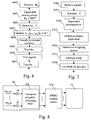
- Fig. 8 is a diagram representing a model of the uplink channel considering the interferences components received by a first telecommunication device.
- the uplink channel between each first telecommunication device 20 1 to 20 K and the second telecommunication device 10 can be, thanks to the present invention, represented by two matrices 800 and 810.
- the coefficients of the matrix 800 are representative of the interference components received by the first telecommunication device 20 k .
- the matrix 810 is the classical channel response matrix H of the MIMO system, the coefficient of which are the complex propagation gain between the antennas of the second telecommunication device 10 and the antennas of the first telecommunication device 20 k .
- the matrix 800 is equal to the transpose of a whitening matrix D .
- the matrix D ( F * ⁇ -1/2 ) T .
- the downlink weighting vector w n is determined considering the virtual channel DH and spatially whitens interference plus noise component z IN ⁇ p .
- the second telecommunication device 10 equivalently determines the downlink weighting vector w n using the knowledge of the virtual channel DH.
- the present invention applies this principle and the first telecommunication device 20 k equivalently sends the pilot signals ⁇ ⁇ r ( p ) through the virtual channel.
- the second telecommunication device 20 can use N' antennas, with N' ⁇ N, instead of N antennas for transferring the signals representative of a least a group of data and/or at least one first telecommunication device 20 can use M' antennas, with M' ⁇ M, instead of M antennas for transferring the weighted pilot signals.
Abstract
Description
- The present invention relates generally to telecommunication systems and in particular, to methods and devices for reporting information related to interference components received by a telecommunication device to another telecommunication device.
- Recently, efficient transmission schemes in space and frequency domains have been investigated to meet the growing demand for high data rate wireless telecommunications. In the space domain, Multi-Input Multi-Output (MIMO) systems using multiple antennas at both transmitter and receiver sides have gained attention to exploit the potential increase of the spectral efficiency.
- The transmission schemes using MIMO systems have been mainly studied from two different approaches. The first approach is related to the case where the telecommunication device transfers simultaneously parallel data streams using an antenna for each of the data streams without having any knowledge about the channel conditions which exist between itself and the telecommunication devices to which the data streams are transferred.
- The second approach is that the telecommunication device which transmits data streams has some knowledge of the channel conditions which exist between itself and the telecommunication devices to which the data streams are transferred. The telecommunication device directs the signals transferred to a telecommunication device according to the channel conditions, and then improves the overall performances of the system.
- Practically, when the channels responses between uplink and downlink channels are reciprocal, e.g. in Time Division Multiplex systems, the channel conditions are obtained according to the following method : a first telecommunication device transfers pilot signals to a second telecommunication device, the second telecommunication device receives the pilot signals, determines the channel responses from the received pilot signals, as example under the form of a channel matrix which is representative of the channel conditions, and uses the determined matrix in order to direct the signals which have to be transferred to the first telecommunication device which has sent the pilot signals.
- The coefficients of the determined channel matrix are the complex propagation gain between the antennas of the second telecommunication device and the antennas of the first telecommunication device.
- Such determination of the channel conditions is effective when the first telecommunication device receives only spatially white noise signals in parallel with the transferred signals by the second telecommunication device.
- Spatially white noise means that the noise received by each antenna of the first telecommunication device have no correlation and have an equal power.
- If the first telecommunication device receives spatially coloured interference components, the second telecommunication device is not aware about these interference components and the second telecommunication device may direct the signals transferred to the first telecommunication device in a wrong direction. As example, the signals received by the first telecommunication device and transferred by the second telecommunication device may have the same direction of the interference components.
- Spatially coloured noise means that the noise received by each antenna of the first telecommunication device are correlated and or have different power.
- If the first telecommunication device is able to measure and report the interference components it receives to the second telecommunication device, it is possible to avoid the above mentioned problem.
- Up to now, it is rather impossible for a telecommunication device to report the measured interference components it receives to another telecommunication device without decreasing in an important manner the bandwidth which is used for classical data transmission.
- The aim of the invention is therefore to propose methods and devices which allow the reporting of information related to interference components received by a telecommunication device to another telecommunication device without decreasing in an important manner the bandwidth of the uplink channel which is used for classical data transmission.
- To that end, the present invention concerns a method for reporting, through a wireless network, information related to interference components received by a first telecommunication device which comprises M antennas to a second telecommunication device which comprises N antennas, characterised in that the method comprises the steps executed by the first telecommunication device of :
- measuring the interference components received by the first telecommunication device,
- determining at most M weighting vectors from the measured interference components,
- weighting at most M pilot signals with the at most M determined weighting vectors,
- transferring the at most M weighted pilot signals to the second telecommunication device.
- The present invention concerns also a device for reporting, through a wireless network, information related to interference components received by a first telecommunication device which comprises M antennas to a second telecommunication device which comprises N antennas, characterised in that the device for reporting information related to interference components is included in the first telecommunication device and comprises :
- means for measuring the interference components received by the first telecommunication device,
- means for determining at most M weighting vectors from the measured interference components,
- means for weighting at most M pilot signals with the at most M determined weighting vectors,
- means for transferring the at most M weighted pilot signals to the second telecommunication device.
- Thus, the first telecommunication device can report the information related to the interference components it receives to a second telecommunication device without decreasing in an important manner the bandwidth which is used for classical data transmission.
- According to a first advantageous embodiment, the first telecommunication device determines at least two matrices from the measured interference components, a first matrix being representative of the spatial direction of the interference components and a second matrix being representative of the power of the noise components and the at most M weighting vectors are determined from the first and second matrices.
- Thus, the first telecommunication device doesn't need any information, like some pilot signals transferred by the second telecommunication device, in order to determine the at most M weighting vectors.
- According to another advantageous embodiment, the first and second matrices are determined by executing an eigenvalue decomposition of an interference correlation matrix R IN obtained from the measured interferences components.
- Thus, the determination of the at most M weighting vectors is simple to execute and reflects precisely the interferences components received by the first telecommunication device.
- According to another advantageous embodiment, M weighting vectors g 1 to gM are determined according to the following formula :
- G = [g1,..., gM] = F*Φ-½ where x* denotes the conjugate of x, F is the first matrix and Φ is the second matrix.
- According to another advantageous embodiment, the first telecommunication device determines a power coefficient, weights the at most M pilot signals by the determined power coefficient and transfers to the second telecommunication device signals representing a power information which is related to the determined power coefficient.
- Thus, if the first telecommunication device adjusts its transmission power, the second telecommunication device is aware about that power adjustment.
- According to still another aspect, the present invention concerns a method for controlling the transfer of signals representative of a group of data to a first telecommunication device by a second telecommunication device through a wireless network, the second telecommunication device having N antennas, the first telecommunication device having M antennas, characterised that in the method comprises the steps executed by the second telecommunication device of :
- receiving at most M pilot signals from the first telecommunication device,
- determining, from the at most M received pilot signals, information representative of interference components received by the first telecommunication device,
- controlling the transfer of the signals representative of the group of data to the first telecommunication device according to the determined information representative of interference components received by the first telecommunication device.
- The present invention concerns also a device for controlling the transfer of signals representative of a group of data to a first telecommunication device by a second telecommunication device through a wireless network, the second telecommunication device having N antennas, the first telecommunication device having M antennas, characterised in that the device for controlling the transfer of signals is included in the second telecommunication device and comprises :
- means for receiving at most M pilot signals from the first telecommunication device,
- means for determining, from the at most M received pilot signals, information representative of interference components received by the first telecommunication device,
- means for controlling the transfer of the signals representative of the group of data to the first telecommunication device according to the determined information representative of interference components received by the first telecommunication device.
- Thus, the second telecommunication device is informed about the interference components received by the first telecommunication device without decreasing in an important manner the bandwidth which is used for classical data transmission, is able to control the transfer of signals to the first telecommunication device in order to reduce the effect of the interference components on the transferred signals representative of a group of data.
- According to another advantageous embodiment, the determined information representative of interference components received by a first telecommunication device is a weighting vector and the control of the transfer of signals representative of a group of data to the first telecommunication device is made by weighting the signals representative of a group of data transferred to the first telecommunication device by the weighting vector.
- Thus, the second telecommunication device can direct the signals transferred to the first telecommunication device according to the information related to interference components received by the first telecommunication device.
- According to another advantageous embodiment, the weighting vector is determined by :
- calculating a matrix J from the at most M received pilot signals,
- executing an eigenvalue decomposition of the product of two matrices obtained from the calculated matrix in order to obtain eigenvectors and eigenvalues,
- selecting the eigenvector corresponding to the largest eigenvalue of the product of the two matrices obtained from the calculated matrix.
- Thus, the determination of the weighting vector is simple.
- According to another advantageous embodiment, the product of two matrices obtained from the calculated matrix is equal to J*JT , where J* denotes the conjugate of J and JT denotes the transpose of J.
- According to another advantageous embodiment, at least two groups of data are transferred simultaneously to the first telecommunication device and an eigenvector is selected for each group of data transferred simultaneously, the selected eigenvectors corresponding to the at least two largest eigenvalues of the product of the two matrices obtained from the calculated matrix.
- Thus, the second telecommunication device can direct the signals representative of each group of data transferred to the first telecommunication device according to the information related to interference components received by the first telecommunication device in order to reduce the effect of the interference components on the transferred signals representative of a group of data.
- According to another advantageous embodiment, the second telecommunication receives from the first telecommunication device signals representing a power information and the information representative of interference components received by the first telecommunication device is determined from the at most M received pilot signals and the power information.
- Thus, if the first telecommunication device adjusts its transmission power, the second telecommunication device is aware about that adjustment.
- According to another advantageous embodiment, the control of the transfer of signals representative of a group of data to the first telecommunication device is the determination of the transmission power to be used for transferring at least a group of data to the first telecommunication device.
- Thus the second telecommunication device can reduce the effect of the interference components received by the first telecommunication device.
- According to another advantageous embodiment, the control of the transfer of signals representative of a group of data to the first telecommunication device is the determination of the modulation and coding scheme to be used for transferring at least signals representative of a group of data to the first telecommunication device.
- Thus, the transfer of signals representing groups of information between the first and the second telecommunication devices is made according to information related to interference components received by the first telecommunication device.
- According to another advantageous embodiment, plural first telecommunication devices transfer pilot signals and signals representative of the power information and the control of the transfer of signals representative of a group of data to the first telecommunication device is made by determining to which first telecommunication device or devices among the plural first telecommunication devices, signals representing at least a group of data have to be transferred.
- Thus, it is possible to allocate the radio resources of the wireless network in an efficient way.
- According to still another aspect, the present invention concerns computer programs which can be directly loadable into a programmable device, comprising instructions or portions of code for implementing the steps of the methods according to the invention, when said computer programs are executed on a programmable device.
- Since the features and advantages relating to the computer programs are the same as those set out above related to the methods and devices according to the invention, they will not be repeated here.
- According to still another aspect, the present invention concerns signals transferred through a wireless network by a first telecommunication device to a second telecommunication device for reporting information related to interference components received by the first telecommunication device which comprises M antennas to the second telecommunication device which comprises N antennas, characterised in that the signals comprise at most M pilot signals which are weighted by at most M weighting vectors determined from measured interference components received by the first telecommunication device.
- Since the features and advantages relating to the signals are the same as those set out above related to the methods and devices according to the invention, they will not be repeated here.
- The characteristics of the invention will emerge more clearly from a reading of the following description of an example embodiment, the said description being produced with reference to the accompanying drawings, among which :
- Fig. 1 is a diagram representing the architecture of the system according to the present invention ;
- Fig. 2 is a diagram representing the architecture of a first telecommunication device according to the present invention;
- Fig. 3 is a diagram representing the architecture of a channel interface of the first telecommunication device;
- Fig. 4 is a diagram representing the architecture of the second telecommunication device according to the present invention;
- Fig. 5 is a diagram representing the architecture of a channel interface of the second telecommunication device;
- Fig. 6 is an algorithm executed by the first telecommunication device according to the present invention;
- Fig. 7 is an algorithm executed by the second telecommunication device according to the present invention;
- Fig. 8 is a diagram representing a model of the uplink channel considering the interferences components received by a first telecommunication device.
- Fig. 1 is a diagram representing the architecture of the system according to present invention.
- In the system of the Fig. 1, at least one and preferably plural
first telecommunication devices wireless network 15 to asecond telecommunication device 10 using an uplink and a downlink channel. - Preferably, and in a non limitative way, the
second telecommunication device 10 is a base station or a node of thewireless network 15. Thefirst telecommunication devices 201 to 20K are terminals like mobile phones or personal computers. - The
telecommunication network 15 is a wireless telecommunication system which uses Time Division Duplexing scheme (TDD). The signals transferred in uplink and downlink channels are duplexed in different time periods of the same frequency band. The signals transferred within thewireless network 15 share the same frequency spectrum. The channel responses between the uplink and downlink channels of thetelecommunication network 15 are reciprocal. - Reciprocal means that if the downlink channel conditions are represented by a downlink matrix, the uplink channel conditions can be expressed by an uplink matrix which is the transpose of the downlink matrix.
- The
second telecommunication device 10 transfers simultaneously signals representatives of at most N groups of data to thefirst telecommunication devices 201 to 20K through the downlink channel and thefirst telecommunication devices 201 to 20K transfer signals to thesecond telecommunication device 10 through the uplink channel. - The signals transferred by the
first telecommunication devices 201 to 20K are signals representatives of a group of data and/or pilot signals which are weighted by at least a weight determined from the interference components measured by thefirst telecommunication devices 201 to 20K. - A group of data is as example a frame constituted at least by a header field and a payload field which comprises classical data like data related to a phone call, or a video transfer and so on.
- Pilot signals are predetermined sequences of symbols known by the telecommunication devices. Pilot signals are as example and in a non limitative way Walsh Hadamard sequences.
- The
second telecommunication device 10 has at least one antenna and more preferably N antennas noted BSAnt1 to BSAntN. Thesecond telecommunication device 10 preferably controls the spatial direction of the signals transferred to afirst telecommunication devices 20 according to at least signals transferred by thefirst telecommunication devices 20 as it will be disclosed hereinafter. - More precisely, when the
second telecommunication device 10 transmits signals representatives of a group of data to a givenfirst telecommunication device 20k through the downlink channel, the signals are N times duplicated and each duplicated signal is weighted, i.e. multiplied, by an element of a downlink weighting vector wn of thesecond telecommunication device 10. As a result, thesecond telecommunication device 10 performs beamforming, i.e. controls the spatial direction of the transmitted signals. - The ellipse noted BF1 in the Fig. 1 shows the pattern of the radiated signals by the antennas BSAnt1 to BSAntN which are transferred to the
first telecommunication device 201 by thesecond telecommunication device 10. - The ellipse noted BFK in the Fig. 1 shows the pattern of the radiated signals by the antennas BSAnt1 to BSAntN which are transferred to the
first telecommunication device 20K by thesecond telecommunication device 10. - The
first telecommunication devices 201 to 20K have M antennas noted respectively MS1Ant1 to MS1AntM and MSKAnt1 to MSKAntM. It has to be noted here that the number M of antennas may vary according to eachfirst telecommunication device 20k with k=1 to K. Eachfirst telecommunication device 201 to 20k controls the spatial direction of the signals transferred to thesecond telecommunication device 10 as it will be disclosed hereinafter. - Each
first telecommunication device 20k transfers through the antennas MSkAnt1 to MSkAntM, the signals to be transmitted to thesecond telecommunication device 10. More precisely, when thefirst telecommunication device 20k transmits signals to thesecond telecommunication device 10 through the uplink channel, the signals are at most M times duplicated and each duplicated signal is weighted, i.e. multiplied, by an element of an uplink weighting vector gm of thefirst telecommunication device 20k, with m =1 to at most M. As a result, thefirst telecommunication device 20k performs beamforming, i.e. controls the spatial direction of the transmitted signals. - The ellipse noted BF 1 in the Fig. 1 shows the pattern of the radiated signals by the antennas MSlAntl to MSIAntM which are transferred by the
first telecommunication device 201 to thesecond telecommunication device 10. - The ellipse noted BFK in the Fig. 1 shows the pattern of the radiated signals by the antennas MSKAnt1 to MSKAntM which are transferred by the
first telecommunication device 20K to thesecond telecommunication device 10. - Fig. 2 is a diagram representing the architecture of a first telecommunication device according to the present invention.
- The
first telecommunication device 20, as example thefirst telecommunication device 20k ,with k comprised between 1 and K, has, for example, an architecture based on components connected together by abus 201 and aprocessor 200 controlled by programs related to the algorithm as disclosed in the Fig. 6. - It has to be noted here that the
first telecommunication device 20 is, in a variant, implemented under the form of one or several dedicated integrated circuits which execute the same operations as the one executed by theprocessor 200 as disclosed hereinafter. - The
bus 201 links theprocessor 200 to a read onlymemory ROM 202, a randomaccess memory RAM 203 and achannel interface 205. - The read only
memory ROM 202 contains instructions of the programs related to the algorithm as disclosed in the Fig. 6 which are transferred, when thefirst telecommunication device 20k is powered on to the randomaccess memory RAM 203. - The
RAM memory 203 contains registers intended to receive variables, and the instructions of the programs related to the algorithm as disclosed in the Fig. 6. - The
channel interface 205 comprises means for measuring the interference plus noise components measured by thefirst telecommunication device 20k, means for weighting at most M the pilot signals to be transferred to thesecond telecommunication device 10 by a power coefficient √η, means for weighting the weighted pilot signals to be transferred to thesecond telecommunication device 10 by weighting vectors gm , with m= 1 to at most M and means for transferring to the second telecommunication device 10 a power information related to the power coefficient. Thechannel interface 205 will be described in more detail in reference to the Fig. 3. - According to the present invention, the
processor 200 determines, from the interference plus noise components measured by thefirst telecommunication device 20k, at most M uplink weighting vectors gm, where m=1 to at most M, to be used for weighting respectively the at most M pilot signals to be transferred to thesecond telecommunication device 10 and determines at least a power coefficient √η to be used for weighting the at most M pilot signals to be transferred to thesecond telecommunication device 10. - Fig. 3 is a diagram representing the architecture of the channel interface of the first telecommunication device.
- The
channel interface 205 comprises aninterference measurement module 300 which measures the interference components received by thefirst telecommunication device 20k. - The interference components are electromagnetic waveforms generated by other first telecommunication devices, electromagnetic waveforms radiated by any electric equipment and/or any other noise received by the
first telecommunication device 20k. - The
second telecommunication device 10 transfers signals representative of nmax , with nmax ≤ N, groups of data simultaneously using different downlink weighting vectors wn = [w n1 ,..., w nN ] T , where n =1 to nmax , ∥wn ∥ = 1. - The signals representative of nmax groups of data are transferred respectively to nmax
first telecommunication devices 20 or the signals representative of at least two groups of data are transferred simultaneously to one or severalfirst telecommunication devices 20. - Assuming that the n-th weighted signal sn(p) received by the
first telecommunication device 20k has a power
first telecommunication device 20k is equal to
where xT denotes the transpose of x, zIN (p) = [z IN,1(p),...,zIN,M (p)] T is the interference plus noise vector of thefirst telecommunication 20k, H is the M*N MIMO channel matrix whose (m,n)-th element is the complex propagation gain between the BSAntn-th antenna of thesecond telecommunication device 10 and the MSkAntm-th antenna of thefirst telecommunication device 20k. - The
interference measurement module 300 measures the interference components received by thefirst telecommunication device 20k and determines an interference correlation matrix R IN by averaging
- Then,

- The
channel interface 205 comprises M means for weighting the pilot signals to be transferred to thesecond telecommunication device 10 by the power coefficient √η. The means for weighting the pilot signals, i.e. multiplying the pilot signals to be transferred to thesecond telecommunication device 10 by the power coefficient √η are noted Mulc1 to MulcM in the Fig. 3. - The
channel interface 205 comprises means for weighting the weighted pilot signals to be transferred to thesecond telecommunication device 10 by weighting vectors gm . The means for weighting the weighted pilot signals to be transferred to thesecond telecommunication device 10 are composed of M duplication modules noted Cp1U to CPMU, M*M uplink multiplication modules noted Mul11U to MulMMU, M uplink summation modules noted Sum1U to SumMU. - The signals R1(t) to RM(t) are the M pilot signals to be transferred to the
second telecommunication 10. The signals R1(t) to RM(t) are multiplied by the multipliers Mulc1 to MulcM by the power coefficient √η. - The weighted, or multiplied, pilot signals are at most M times duplicated by a respective duplication module CP1U to CPMU. Each duplicated signal is weighted by the elements of a uplink weighting vector gm determined by the
processor 200. The combination of each signals transferred to thesecond telecommunication device 10 by the antennas MSkAnt1 to MSAntM is called beamforming signal. - The signals weighted by the first element of each uplink weighting vector gm are then summed by the adder Sum1U and transferred through the first antenna MSkAnt1 of the
first telecommunication device 20k. The signals weighted by the second element of each uplink weighting vector gm are then summed and transferred through the second antenna MSkAnt2 and so on until the M-th elements of the weighting vector gm . - It has to be noted here that the signals are, prior to be transferred to each antenna MSkAnt1 to MSkAntM, frequency up converted, mapped and so on, as it is done in classical wireless telecommunication devices.
- It has to be noted here that, less than M pilot signals, as example M' pilot signals with M' ≤ M, can be transferred to the
second telecommunication 10 as it will be disclosed hereinafter. Thechannel interface 205 comprises M' means for weighting the pilot signals to be transferred to thesecond telecommunication device 10, the means for weighting the weighted pilot signals to be transferred to thesecond telecommunication device 10 are composed of M' duplication modules, M*M' uplink multiplication modules and M uplink summation modules. - Fig. 4 is a diagram representing the architecture of the second telecommunication device according to the present invention.
- The
second telecommunication device 10, has, for example, an architecture based on components connected together by abus 401 and aprocessor 400 controlled by programs related to the algorithm as disclosed in the Fig. 7. - It has to be noted here that the
second telecommunication device 10 is, in a variant, implemented under the form of one or several dedicated integrated circuits which execute the same operations as the one executed by theprocessor 400 as disclosed hereinafter. - The
bus 401 links theprocessor 400 to a read onlymemory ROM 402, a randomaccess memory RAM 403 and achannel interface 405. - The read only
memory ROM 402 contains instructions of the programs related to the algorithm as disclosed in the Fig. 7 which are transferred, when thesecond telecommunication 10 is powered onto the randomaccess memory RAM 403. - The
RAM memory 403 contains registers intended to receive variables, and the instructions of the programs related to the algorithm as disclosed in the Fig. 7. - According to the present invention, the
processor 400 is able to determine, for eachfirst telecommunication device 201 to 20K, from at least signals transferred by each first telecommunication device, the downlink weighting vector wn to be used by thesecond telecommunication device 10 when it transfers signals to eachfirst telecommunication device 201 to 20K. Theprocessor 400 is also able to determine the modulation and coding scheme to be used by eachfirst telecommunication device 20k and/or to determine to whichfirst telecommunication device 20, signals representative of a group of data have to be sent according to signals transferred by thefirst telecommunication devices 20. Theprocessor 400 is also able to adjust the transmission power by setting at least a predicted SINR to a predetermined SINR. - The
channel interface 405 comprises means for receiving weighted pilot signals from eachfirst telecommunication device 201 to 20K, means for receiving, from eachfirst telecommunication device 201 to 20K, a respective power information. Thechannel interface 405 comprises means for directing, using the downlink weighting vectors wn , the signals representatives of groups of data transferred by thesecond telecommunication device 10 to eachfirst telecommunication device 201 to 20K. Thechannel interface 405 will be disclosed in more details in reference to the Fig. 5. - Fig. 5 is a diagram representing the architecture of a channel interface of the second telecommunication device.
- The
channel interface 405 of thesecond telecommunication device 10 comprises a pilotsignal reception module 500, N duplication modules noted Cp1 to CPN, N*N downlink multiplication modules noted Mul11D to MulNND and at most N downlink summation modules noted Sum1D to SumND. - The pilot
signal reception module 500 comprises means for receiving pilot signals and means for receiving a power information from each of thefirst telecommunication devices 201 to 20K. - The signals S1(t) to SN(t) are the signals, which are respectively representative of N groups of data, to be transferred simultaneously to the
K terminals 201 to 20K linked to thesecond telecommunication device 10. Each of the signals S1(t) to SN(t) are N times duplicated by a respective duplication module Cp1 to CPN. Each duplicated signal is weighted by the elements of a downlink weighting vector wn corresponding to the group of data noted n, with n=1 to N, to be transferred to the terminal 20k. The combination of the signals transferred to a terminal 20k by the antennas BSAnt1 to BSAntN is called beamforming signal. - The signals weighted by the first element of each downlink weighting vector wn of the
second telecommunication device 10 are summed by the adder Sum1D and transferred through the first antenna BSAnt1 of thesecond telecommunication device 10. The signals weighted by the second element of each weighting vector wn are summed and transferred through the second antenna BSAnt2 of thesecond telecommunication device 10 and so on until the N-th element of each weighting vector wn of thesecond telecommunication device 10. - It has to be noted here that the signals are, prior to be transferred to each antenna BSAnt1 to BSAntN, frequency up converted, mapped and so on, as it is done in classical wireless telecommunication devices.
- It has to be noted here that, less than N groups of data can be transferred simultaneously, as example N' pilot signals with N'≤N, can be transferred simultaneously. The means for weighting the signals representative of a group of data are composed of N' duplication modules, N*N' uplink multiplication modules and N uplink summation modules.
- Fig. 6 is an algorithm executed by the first telecommunication device according to the present invention.
- The present algorithm is more precisely executed by each of the
first telecommunication devices 201 to 20K. - At step S600, the
processor 200 of thefirst telecommunication devices 20k receives, from theinterference measurement module 300 of thechannel interface 205, the interference correlation matrix R IN of thefirst telecommunication device 20k. The interference correlation matrix R IN is representative of the interference components generated by other first telecommunication devices and/or any other electric devices and/or any other noise received by thefirst telecommunication device 20k. - At next step S401, the
processor 200 executes an eigenvalue decomposition of the interference correlation matrix R IN . R IN = FΦ FH , where Φ and F are M*M diagonal and unitary matrices and xH denotes the complex conjugate transpose of the matrix x. - It has to be noted here that the matrix F is representative of the spatial direction of the received noise components and the matrix Φ is proportional to the power of the received interference components.
- At next step S402, the
processor 200 determines a power coefficient √η. The power coefficient √η can be set to any value or to a predetermined value known by all thecommunication devices - In a particular mode of realisation of the present invention, η is equal to

first telecommunication device 20k and tr{x} is the trace of the matrix x i.e. the sum of diagonal elements of the matrix x. - At next step S603, the
processor 200 calculates the uplink weighting vectors g m = [g m,1,..., gm,M ] T ,with m=1 to M, using the following formula: - G = [g 1,..., gM ] = F*Φ - ½ where x* denotes the conjugate of x.
- At next step S604 the
processor 200 transfers the uplink weighting vectors gm = [g m,1,...,gm,M ] T , with m=1 to M to thechannel interface 205. - In a variant of realisation, if some coefficients of the matrix Φ is lower than a predetermined threshold, the
processor 200 doesn't transfer the corresponding uplink weighting vector to thechannel interface 205. In such case, a reduced number of pilot signals need then to be transferred to thesecond telecommunication device 10. - The number of pilot symbols can either be reduced by setting at least one of them to null value.
- At step S605, the
processor 200 transfers the power coefficient √η to thechannel interface 205. The power coefficient √η is used for weighting the pilot signals to be transferred to thesecond telecommunication device 10. - At next step S606, the
processor 200 transfers at most M pilot signals to thechannel interface 205. The pilot signal rm (p) , with m=1 to at most M, transferred from the m-th antenna has p 0 symbols which are mutually orthogonal as :
- At next step S007, each of the at most M pilot signals are duplicated at most M times. Each duplicated pilot signal is weighted by the elements of an uplink weighting vector gm = [g m,1,..., gm,M ] T , with m= 1 to at most M, and transferred to the
second telecommunication device 10. The power information η related to the power coefficient √η is also transferred to thesecond telecommunication device 10 at the same step. It has to be noted here that, if the power coefficient is equal to the predetermined value, the power information is not transferred. - The power information η represents the multiplying factor used by the
first telecommunication device 20k for weighting the pilot signals. - Fig. 7 is an algorithm executed by the second telecommunication device according to the present invention.
- The step S700 to S705 are executed in parallel for the pilot signals received from each of the
first telecommunication devices 201 to 20K. - At step S700, the signals transferred at step S606 by a
first telecommunication 20, are received by the pilotsignal reception module 500 of thechannel interface 405 of thesecond telecommunication device 10. The p-th sample noted xA (p) of the received signal of the of the pilot signals with m=1 to M is expressed as:
xA (p) = √ηHT Gr(p) + zA (p), wherein r(p) = [r 1(p),..., rM (p)] T denotes the pilot signal transferred through all the M antennas of thefirst telecommunication device 20k, zA (p) = [z A,1(p),...,zA,N (p)] T is thesecond telecommunication device 10 interference plus noise component and H is the downlink MIMO channel matrix. Since the channel is reciprocal in the downlink and uplink channels, the uplink MIMO channel matrix is expressed as HT . - At next step S701, the
processor 400 estimates the product of matrices HTG. - The received signals p = 1,..., p 0 are totally expressed in matrix form as :


where

- Then, the
processor 400 estimates HT G as
- If ZA = 0, it holds that

- At next step S702, the
processor 400 makes an eigenvalue decomposition of J*JT . - At next step S703, the
processor 400 determines the largest eigenvalue noted ρ〈J*JT〉 of the matrix J*JT. - It has to be noted here that, if at least two groups of data have to be transferred in parallel to the
first telecommunication device 20k, theprocessor 400 determines the at least two largest eigenvalues of the matrix J*JT. - At next step S704, the
processor 400 determines the downlink weighting vector wn to be used for transferring signals representative of the n-th group of data to thefirst telecommunication device 20k which has transferred the signals received at step S700. - If at least two groups of data have to be transferred in parallel to the first telecommunication device, the
processor 400 determines at least two downlink weighting vectors to be used for transferring signals representing the at least two groups of data to thefirst telecommunication device 20k which has transferred the signals received at step S700. - The
processor 400 determines the downlink weighting vector wn as the eigenvector noted e 〈 J* JT 〉 which corresponds to largest the eigenvalue ρ 〈 J* JT 〉 or if at least two groups of data have to be transferred in parallel to the first telecommunication device, theprocessor 400 determines the at least two downlink weighting vectors as the eigenvector which corresponds to largest the at least two eigenvalues. - At next step S705, the
processor 400 estimates the Signal-to-Interference-plus-Noise-Ratio (SINR) of thefirst telecommunication device 20k which has transferred the signals received at step S700. - The SINR


- As

second telecommunication devices 10 uses the power information in order to predict the SINR of thefirst telecommunication device 20k. - It has to be noted here that in a variant of realisation, the
second telecommunication device 10 adjusts the transmission power
- It has also to be noted here that the
second telecommunication device 10 can direct the signals transferred to thefirst telecommunication device 20k which has transferred the signals received at step S700 considering the effect of interferences on thefirst telecommunication device 20k without having the complete knowledge of H and R IN as it is usually the case in the prior art. - At next step S706, the
processor 400 determine the modulation and coding scheme to be used for transferring group of data to thefirst telecommunication device 20k using the determined SINR or, using the determined SINR of all thefirst telecommunication devices 201 to 20K, theprocessor 400 determines thefirst telecommunication device 20 to which, signals representative of a group of data have to be sent. - It has to be noted here that the downlink weighting vector w n can be obtained without the power information because the fact that the matrix J is multiplied by a coefficient has no effect on en 〈J*JT 〉.
- Fig. 8 is a diagram representing a model of the uplink channel considering the interferences components received by a first telecommunication device.
- The uplink channel between each
first telecommunication device 201 to 20K and thesecond telecommunication device 10 can be, thanks to the present invention, represented by twomatrices - The coefficients of the
matrix 800 are representative of the interference components received by thefirst telecommunication device 20k. Thematrix 810 is the classical channel response matrix H of the MIMO system, the coefficient of which are the complex propagation gain between the antennas of thesecond telecommunication device 10 and the antennas of thefirst telecommunication device 20k. - The
matrix 800 is equal to the transpose of a whitening matrix D . - According to the invention, the matrix D = (F*Φ-1/2) T .
- The matrix D corresponds to a spatial whitening matrix which whitens the interference plus noise component zIN (p) of the
first telecommunication device 20k as

- Hence, the received signal x(p)' after spatial whitening process is expressed as :

- Considering the virtual channel expressed by the product of the matrix D and H, the downlink weighting vector wn is determined considering the virtual channel DH and spatially whitens interference plus noise component

- Therefore, the
second telecommunication device 10 equivalently determines the downlink weighting vector wn using the knowledge of the virtual channel DH. - The present invention applies this principle and the
first telecommunication device 20k equivalently sends the pilot signals √ ηr(p) through the virtual channel. - Then, the signals transferred by
first telecommunication device 20k are expressed as √ ηr(p) = Gr(p). Since the interference plus noise component is whitened in the virtual channel, it is not necessary to feed back the correlation coefficients of interference plus noise between the antennas offirst telecommunication device 20k. Consequently, the proposed method doesn't need to feedback any information or needs only to feeds back only the power information related to the power coefficient. - Naturally, many modifications can be made to the embodiments of the invention described above without departing from the scope of the present invention. As example, the
second telecommunication device 20 can use N' antennas, with N'<N, instead of N antennas for transferring the signals representative of a least a group of data and/or at least onefirst telecommunication device 20 can use M' antennas, with M'<M, instead of M antennas for transferring the weighted pilot signals.
Claims (19)
- Method for reporting, through a wireless network, information related to interference components received by a first telecommunication device which comprises M antennas to a second telecommunication device which comprises N antennas, characterised in that the method comprises the steps executed by the first telecommunication device of :- measuring the interference components received by the first telecommunication device,- determining at most M weighting vectors from the measured interference components,- weighting at most M pilot signals with the at most M determined weighting vectors,- transferring the at most M weighted pilot signals to the second telecommunication device.
- Method according to claim 1, characterised in that the method comprises further step of determining at least two matrices from the measured interference components, a first matrix being representative of the spatial direction of the interference components and a second matrix being representative of the power of the noise components and the at most M weighting vectors are determined from the first and second matrices.
- Method according to claim 2, characterised in that the first and second matrices are determined by executing an eigenvalue decomposition of an interference correlation matrix R IN obtained from the measured interferences components.
- Method according to claim 3, characterised in that the M weighting vectors g 1 to gM are determined according to the following formula :
G = [g1,..., gM ] = F*Φ-½ where x* denotes the conjugate of x, F is the first matrix and Φ is the second matrix. - Method according to claims 2 to 4, characterised in that the method further comprises the steps of :- determining a power coefficient,- weighting the at most M pilot signals by the power coefficient,- transferring to the second telecommunication device signals representing a power information which is related to the determined power coefficient.
- Method for controlling the transfer of signals representative of a group of data to a first telecommunication device by a second telecommunication device through a wireless network, the second telecommunication device having N antennas, the first telecommunication device having M antennas, characterised in that the method comprises the steps executed by the second telecommunication device of :- receiving at most M pilot signals from the first telecommunication device,- determining, from the at most M received pilot signals, information representative of interference components received by the first telecommunication device,- controlling the transfer of the signals representative of the group of data to the first telecommunication device according to the determined information representative of interference components received by the first telecommunication device.
- Method according to claim 6, characterised in that the determined information representative of interference components received by a first telecommunication device is a weighting vector and in that the control of the transfer of signals representative of a group of data to the first telecommunication device is made by weighting the signals representative of a group transferred to the first telecommunication device of data by the weighting vector.
- Method according to claim 7, characterised in that the weighting vector is determined by :- calculating a matrix J from the at most M received pilot signals,- executing an eigenvalue decomposition of the product of two matrices obtained from the calculated matrix in order to obtain eigenvectors and eigenvalues,- selecting the eigenvector corresponding to the largest eigenvalue of the product of the two matrices obtained from the calculated matrix.
- Method according to claim 8, characterised in that the product of two matrices obtained from the calculated matrix is equal to J*JT , where J* denotes the conjugate of J and JT denotes the transpose of J.
- Method according to claim 8 or 9, characterised in that at least two groups of data are transferred simultaneously to the first telecommunication device and in that an eigenvector is selected for each group of data transferred simultaneously, the selected eigenvectors corresponding to the at least two largest eigenvalues of the product of the two matrices obtained from the calculated matrix.
- Method according to any of the claim 6 to 10, characterised in that the method comprises further step of receiving from the first telecommunication device signals representing a power information and in that the information representative of interference components received by the first telecommunication device is determined from the M received pilot signals and the power information.
- Method according to claim 11, characterised in that the control of the transfer of signals representative of a group of data to the first telecommunication device is the determination of the transmission power to be used for transferring at least a group of data to the first telecommunication device.
- Method according to claim 11 or 12, characterised in that the control of the transfer of signals representative of a group of data to the first telecommunication device is the determination of the modulation and coding scheme to be used for transferring at least signals representative of a group of data to the first telecommunication device.
- Method according to any of the claims 11 to 13, characterised in that plural first telecommunication devices transfer pilot signals and signals representative of the power information and in that the control of the transfer of signals representative of a group of data to the first telecommunication device is the determination to which first telecommunication device or devices among the plural first telecommunication devices, signals representing at least a group of data have to be transferred.
- Device for reporting, through a wireless network, information related to interference components received by a first telecommunication device which comprises M antennas to a second telecommunication device which comprises N antennas, characterised in that the device for reporting information related to interference components is included in the first telecommunication device and comprises :- means for measuring the interference components received by the first telecommunication device,- means for determining at most M weighting vectors from the measured interference components,- means for weighting at most M pilot signals with the at most M determined weighting vectors,- means for transferring the at most M weighted pilot signals to the second telecommunication device.
- Device for controlling the transfer of signals representative of a group of data to a first telecommunication device by a second telecommunication device through a wireless network, the second telecommunication device having N antennas, the first telecommunication device having M antennas, characterised in that the device for controlling the transfer of signals is included in the second telecommunication device and comprises :- means for receiving at most M pilot signals from the first telecommunication device,- means for determining, from the at most M received pilot signals, information representative of interference components received by the first telecommunication device,- means for controlling the transfer of the signals representative of the group of data to the first telecommunication device according to the determined information representative of interference components received by the first telecommunication device.
- Computer program which can be directly loadable into a programmable device, comprising instructions or portions of code for implementing the steps of the method according to claims 1 to 5, when said computer program is executed on a programmable device.
- Computer program which can be directly loadable into a programmable device, comprising instructions or portions of code for implementing the steps of the method according to claims 6 to 14, when said computer program is executed on a programmable device.
- Signals transferred through a wireless network by a first telecommunication device to a second telecommunication device for reporting information related to interference components received by the first telecommunication device which comprises M antennas to the second telecommunication device which comprises N antennas, characterised in that the signals comprise at most M pilot signals which are weighted by at most M weighting vectors determined from measured interference components received by the first telecommunication device.
Priority Applications (4)
| Application Number | Priority Date | Filing Date | Title |
|---|---|---|---|
| EP05292816A EP1804394A1 (en) | 2005-12-27 | 2005-12-27 | Method and device for reporting information related to interference components received by a first telecommunication device to a second telecommunication device |
| US11/611,549 US7778605B2 (en) | 2005-12-27 | 2006-12-15 | Method and device for reporting information related to interference components received by a first telecommunication device to a second telecommunication device |
| CN2006100644447A CN101030825B (en) | 2005-12-27 | 2006-12-26 | Method and device for reporting information related to interference components received by a first telecommunication device to a second telecommunication device |
| JP2006352282A JP5049587B2 (en) | 2005-12-27 | 2006-12-27 | Method, apparatus, and signal for reporting information related to interference component, method and apparatus for controlling signal transfer, and computer program |
Applications Claiming Priority (1)
| Application Number | Priority Date | Filing Date | Title |
|---|---|---|---|
| EP05292816A EP1804394A1 (en) | 2005-12-27 | 2005-12-27 | Method and device for reporting information related to interference components received by a first telecommunication device to a second telecommunication device |
Publications (1)
| Publication Number | Publication Date |
|---|---|
| EP1804394A1 true EP1804394A1 (en) | 2007-07-04 |
Family
ID=35997922
Family Applications (1)
| Application Number | Title | Priority Date | Filing Date |
|---|---|---|---|
| EP05292816A Withdrawn EP1804394A1 (en) | 2005-12-27 | 2005-12-27 | Method and device for reporting information related to interference components received by a first telecommunication device to a second telecommunication device |
Country Status (4)
| Country | Link |
|---|---|
| US (1) | US7778605B2 (en) |
| EP (1) | EP1804394A1 (en) |
| JP (1) | JP5049587B2 (en) |
| CN (1) | CN101030825B (en) |
Cited By (1)
| Publication number | Priority date | Publication date | Assignee | Title |
|---|---|---|---|---|
| GB2466070A (en) * | 2008-12-12 | 2010-06-16 | Nokia Corp | A MIMO transmitter for generating a pilot signal using at least two weighting coefficients, and a MIMO receiver for estimating SINR from two such signals |
Families Citing this family (6)
| Publication number | Priority date | Publication date | Assignee | Title |
|---|---|---|---|---|
| US7877097B2 (en) * | 2006-11-06 | 2011-01-25 | Fujitsu Limited | Reuse pattern network scheduling using interference levels |
| US7643429B2 (en) * | 2006-11-06 | 2010-01-05 | Fujitsu Limited | Interference measuring and mapping method and apparatus for wireless networks using relay stations |
| US20080171551A1 (en) * | 2007-01-11 | 2008-07-17 | Fujitsu Limited | Reuse pattern network scheduling using load levels |
| US8599969B2 (en) * | 2009-08-13 | 2013-12-03 | Qualcomm Incorporated | Communications channel estimation |
| US11095391B2 (en) * | 2018-12-19 | 2021-08-17 | Nxp Usa, Inc. | Secure WiFi communication |
| CN114244414B (en) * | 2021-11-08 | 2024-04-12 | 华为技术有限公司 | Signal processing method and related device |
Citations (4)
| Publication number | Priority date | Publication date | Assignee | Title |
|---|---|---|---|---|
| WO2003001761A1 (en) * | 2001-06-22 | 2003-01-03 | Qualcomm Incorporated | Method and apparatus for transmitting data in a time division duplex system |
| US6584302B1 (en) * | 1999-10-19 | 2003-06-24 | Nokia Corporation | Method and arrangement for forming a beam |
| WO2004038985A2 (en) | 2002-10-25 | 2004-05-06 | Qualcomm Incorporated | Multi-mode terminal in a wireless mimo system with spatial multiplexing |
| EP1521383A1 (en) * | 2003-09-30 | 2005-04-06 | Lucent Technologies Inc. | Method for optimizing the transmit covariance in multiple antenna wireless links |
Family Cites Families (10)
| Publication number | Priority date | Publication date | Assignee | Title |
|---|---|---|---|---|
| JP2002261670A (en) * | 2001-02-27 | 2002-09-13 | Yrp Mobile Telecommunications Key Tech Res Lab Co Ltd | Wireless transmitting apparatus and wireless receiving apparatus |
| US7039363B1 (en) * | 2001-09-28 | 2006-05-02 | Arraycomm Llc | Adaptive antenna array with programmable sensitivity |
| KR100795824B1 (en) * | 2001-12-08 | 2008-01-17 | 주식회사 세스텍 | Signal Processing Method and Apparatus for Antenna Array System Providing a Diversity Gain |
| JP4350491B2 (en) * | 2002-12-05 | 2009-10-21 | パナソニック株式会社 | Wireless communication system, wireless communication method, and wireless communication apparatus |
| US7362830B2 (en) * | 2002-12-31 | 2008-04-22 | Lg Electronics Inc. | Smart antenna system and method |
| JP4039413B2 (en) * | 2003-11-05 | 2008-01-30 | ソニー株式会社 | Wireless communication system, wireless communication method, and wireless communication apparatus |
| US7457590B2 (en) * | 2003-12-23 | 2008-11-25 | Motorola, Inc. | Method, apparatus and system for use in the transmission of wireless communications using multiple antennas |
| CN1281003C (en) * | 2004-02-26 | 2006-10-18 | 上海交通大学 | Time-domain adaptive channel estimating method based on pilot matrix |
| ATE523978T1 (en) * | 2005-12-27 | 2011-09-15 | Mitsubishi Electric Corp | METHOD AND DEVICE FOR NOTIFYING TO A SECOND TELECOMMUNICATIONS DEVICE INFORMATION RELATING TO INTERFERENCE COMPONENTS RECEIVED IN A FIRST TELECOMMUNICATIONS DEVICE IN CERTAIN FREQUENCY SUB-BANDS |
| US8000418B2 (en) * | 2006-08-10 | 2011-08-16 | Cisco Technology, Inc. | Method and system for improving robustness of interference nulling for antenna arrays |
-
2005
- 2005-12-27 EP EP05292816A patent/EP1804394A1/en not_active Withdrawn
-
2006
- 2006-12-15 US US11/611,549 patent/US7778605B2/en not_active Expired - Fee Related
- 2006-12-26 CN CN2006100644447A patent/CN101030825B/en not_active Expired - Fee Related
- 2006-12-27 JP JP2006352282A patent/JP5049587B2/en not_active Expired - Fee Related
Patent Citations (4)
| Publication number | Priority date | Publication date | Assignee | Title |
|---|---|---|---|---|
| US6584302B1 (en) * | 1999-10-19 | 2003-06-24 | Nokia Corporation | Method and arrangement for forming a beam |
| WO2003001761A1 (en) * | 2001-06-22 | 2003-01-03 | Qualcomm Incorporated | Method and apparatus for transmitting data in a time division duplex system |
| WO2004038985A2 (en) | 2002-10-25 | 2004-05-06 | Qualcomm Incorporated | Multi-mode terminal in a wireless mimo system with spatial multiplexing |
| EP1521383A1 (en) * | 2003-09-30 | 2005-04-06 | Lucent Technologies Inc. | Method for optimizing the transmit covariance in multiple antenna wireless links |
Cited By (3)
| Publication number | Priority date | Publication date | Assignee | Title |
|---|---|---|---|---|
| GB2466070A (en) * | 2008-12-12 | 2010-06-16 | Nokia Corp | A MIMO transmitter for generating a pilot signal using at least two weighting coefficients, and a MIMO receiver for estimating SINR from two such signals |
| US8553803B2 (en) | 2008-12-12 | 2013-10-08 | Nokia Corporation | Estimation of the signal to interference and noise ratio (SINR) in multiple input multiple output (MIMO) systems |
| GB2466070B (en) * | 2008-12-12 | 2014-04-30 | Nokia Corp | An apparatus |
Also Published As
| Publication number | Publication date |
|---|---|
| JP5049587B2 (en) | 2012-10-17 |
| US20070207769A1 (en) | 2007-09-06 |
| CN101030825B (en) | 2012-07-04 |
| JP2007189682A (en) | 2007-07-26 |
| CN101030825A (en) | 2007-09-05 |
| US7778605B2 (en) | 2010-08-17 |
Similar Documents
| Publication | Publication Date | Title |
|---|---|---|
| EP1804409B1 (en) | Method and device for reporting information related to interference components received by a first telecommunication device in some frequency subbands to a second telecommunication device | |
| EP1394963B1 (en) | Apparatus and method for transmitting and receiving signals using multi-antennas | |
| US6927728B2 (en) | Method and apparatus for multi-antenna transmission | |
| KR100575993B1 (en) | Method and apparatus for scheduling multi-user in wireless communication system using multiple transmit/receive antenna | |
| EP1775857B1 (en) | Apparatus and method for transmitting/receiving data in multi-user multi-antenna communication system | |
| US9935693B2 (en) | Method for communicating in a MIMO network | |
| US20130315350A1 (en) | Wireless communications system, wireless communications apparatus, wireless communications method and computer program for wireless communication | |
| US7778605B2 (en) | Method and device for reporting information related to interference components received by a first telecommunication device to a second telecommunication device | |
| US9276658B2 (en) | Method for communicating in a MIMO network | |
| EP1871017A1 (en) | Method and device for reporting, through a wireless network, a channel state information between a first telecommunication device and a second telecommunication device | |
| US20120057645A1 (en) | method for communicating in a network | |
| EP1780907B1 (en) | Method for controlling the transmission of signals | |
| US20100279699A1 (en) | Method and device for controlling channel state information transferred by a first telecommunication device to a second telecommunication device | |
| CN107872262B (en) | Method and device for improving data forming gain, base station and communication system | |
| EP2008381B1 (en) | Method for transferring power information used by a telecommunication device for weighting at least one pilot signal | |
| KR100905549B1 (en) | Method and Apparatus for Selection of Transmitting Antennas In Uplink of MIMO Wireless Communication System |
Legal Events
| Date | Code | Title | Description |
|---|---|---|---|
| PUAI | Public reference made under article 153(3) epc to a published international application that has entered the european phase |
Free format text: ORIGINAL CODE: 0009012 |
|
| AK | Designated contracting states |
Kind code of ref document: A1 Designated state(s): AT BE BG CH CY CZ DE DK EE ES FI FR GB GR HU IE IS IT LI LT LU LV MC NL PL PT RO SE SI SK TR |
|
| AX | Request for extension of the european patent |
Extension state: AL BA HR MK YU |
|
| 17P | Request for examination filed |
Effective date: 20070818 |
|
| 17Q | First examination report despatched |
Effective date: 20070920 |
|
| AKX | Designation fees paid |
Designated state(s): AT BE BG CH CY CZ DE DK EE ES FI FR GB GR HU IE IS IT LI LT LU LV MC NL PL PT RO SE SI SK TR |
|
| RAP1 | Party data changed (applicant data changed or rights of an application transferred) |
Owner name: MITSUBISHI DENKI KABUSHIKI KAISHA Owner name: MITSUBISHI ELECTRIC R&D CENTRE EUROPE B.V. |
|
| STAA | Information on the status of an ep patent application or granted ep patent |
Free format text: STATUS: THE APPLICATION IS DEEMED TO BE WITHDRAWN |
|
| 18D | Application deemed to be withdrawn |
Effective date: 20110914 |