EP1801583B1 - Container for medical consumables, with desiccant compartment - Google Patents
Container for medical consumables, with desiccant compartment Download PDFInfo
- Publication number
- EP1801583B1 EP1801583B1 EP05028293A EP05028293A EP1801583B1 EP 1801583 B1 EP1801583 B1 EP 1801583B1 EP 05028293 A EP05028293 A EP 05028293A EP 05028293 A EP05028293 A EP 05028293A EP 1801583 B1 EP1801583 B1 EP 1801583B1
- Authority
- EP
- European Patent Office
- Prior art keywords
- magazine
- container
- supply
- container system
- seal
- Prior art date
- Legal status (The legal status is an assumption and is not a legal conclusion. Google has not performed a legal analysis and makes no representation as to the accuracy of the status listed.)
- Not-in-force
Links
Images

Classifications
-
- G—PHYSICS
- G01—MEASURING; TESTING
- G01N—INVESTIGATING OR ANALYSING MATERIALS BY DETERMINING THEIR CHEMICAL OR PHYSICAL PROPERTIES
- G01N33/00—Investigating or analysing materials by specific methods not covered by groups G01N1/00 - G01N31/00
- G01N33/48—Biological material, e.g. blood, urine; Haemocytometers
- G01N33/483—Physical analysis of biological material
- G01N33/487—Physical analysis of biological material of liquid biological material
- G01N33/4875—Details of handling test elements, e.g. dispensing or storage, not specific to a particular test method
- G01N33/48764—Test tape taken off a spool
-
- G—PHYSICS
- G01—MEASURING; TESTING
- G01N—INVESTIGATING OR ANALYSING MATERIALS BY DETERMINING THEIR CHEMICAL OR PHYSICAL PROPERTIES
- G01N33/00—Investigating or analysing materials by specific methods not covered by groups G01N1/00 - G01N31/00
- G01N33/48—Biological material, e.g. blood, urine; Haemocytometers
- G01N33/483—Physical analysis of biological material
- G01N33/487—Physical analysis of biological material of liquid biological material
- G01N33/4875—Details of handling test elements, e.g. dispensing or storage, not specific to a particular test method
- G01N33/48778—Containers specially adapted therefor, e.g. for dry storage
Definitions
- the invention relates to a repackaging system for medical test elements, which are accommodated in a removable from the outer packaging magazine.
- DE 198 109 407 A1 refers to a test strip container for meters that use disposable test strips. These disposable test strips are usually fed to a sensor for measurement.
- the container in which the disposable test strips are received comprises two parts, in the first part of which the test strips are stored and in the second part of which the used test strips are collected.
- Another test strip container is off DE 3 519 296 known.
- test elements that are used for blood glucose measurement for lactate measurement or for cholesterol determination in measuring instruments, is in a z. B. wrapped packaging designed to protect the medical supplies from environmental influences. Test elements for medical purposes are particularly sensitive to temperature fluctuations and in particular to moisture. As a result, magazines in which a number of test elements are generally received are welded into the outer packaging in order to prevent moisture from entering the outer packaging and thus damaging the magazine contained in the outer packaging with the moisture-proofing test elements.
- the outer packaging which is generally water-vapor-tight and which is received for sale in a sales packaging, contains a desiccant supply.
- the magazine in which the test elements are accommodated also contains a desiccant reservoir.
- the desiccant supply in the magazine with the test elements serves to during the period between the production of the test elements to their consumption by the user to protect the test elements contained in the magazine from water vapor loading. It can thus be achieved that the test elements have a storage life independent of the storage duration, since during this period the desiccant supply within the magazine receiving the test elements absorbs a diffusing water vapor and keeps it away from the test elements contained in the magazine.
- the cassette is sealed after the assembly with the conveyor belt, on which the individual test elements are applied, and in a z. B. inserted as an aluminum pot outer packaging and welded together with a likewise introduced into the outer packaging desiccant in the outer packaging. When the outer packaging is closed, the desiccant supply contained therein ensures during storage that no ambient moisture will be absorbed by the cassette during storage.
- a disadvantage of the above-described solution according to the current state of the art is the fact that in the manufacturing process, both the desiccant and the test elements are inevitably loaded with water vapor.
- the test elements contained therein and the desiccant contained in the magazine are partially laden with production-related moisture.
- the desiccant supply contained in the magazine has only a residual capacity for penetrating moisture.
- the desiccant supply contained in the magazine first dries the interior of the magazine, the remaining residual capacity of the desiccant store contained in the magazine serves to ensure the durability of the test elements in the magazine.
- the invention has for its object to provide a repackaging system for medical test elements, which increases the durability (on-board stability) of the test elements.
- a connection between the desiccant reservoir in the outer packaging and the desiccant reservoir in the test elements receiving magazine are created, which, as long as the outer packaging is closed, a connection between the in the desiccant recorded desiccant and the desiccant contained in the magazine produces.
- the connection between the desiccant supply of the outer packaging and the desiccant supply contained in the magazine can, for. B. are created by a spacer or spacer, which is on the one hand connected to the outer packaging, and which on the other hand lies between a seal and the housing of the recorded in the outer packaging magazine with the test elements.
- the spacer or spacer By the spacer or spacer, the z. B. as a band having a porous portion as a fabric structure, as a non-woven or a thread mesh can be made, an opening between the seal of the magazine and the interior of the outer packaging is created, which exists as long as the test elements receiving magazine in the water vapor-tight envelope of the outer packaging is added.
- the desiccant stored in the outer packaging can be used to reduce the one hand, the production-related moisture content of the test elements contained in the magazine and absorb storage moisture due to storage time in the outer packaging.
- the opening previously created by the spacer or spacer between the housing of the magazine and the seal and the desiccant reservoir contained in the outer packaging is closed to a production-related residual size.
- this preferred embodiment of the present invention is when opening the outer packaging of the outer packaging of the connected to the outer packaging spacer or spacer pulled out of the opening between the seal and the magazine, whereby the opening assumes its residual size.
- the spacer or spacers made of a porous, a water vapor diffusion permitting material, so absorbed in the outer package desiccant can draw water vapor from the inside of the magazine, which on the recorded between the housing of the magazine with the seal spacers or spacers in the cavity
- Outer packaging can be absorbed by the larger desiccant supply contained therein.
- the spacer or the spacer after opening the outer packaging can be manually pulled out of the opening between the seal and the magazine, so that the opening of the magazine associated seal from its inactive position in their active , ie sealing position is transferred.
- the transfer of the seal from its inactive state takes place in the closed state of the outer packaging in its active position after opening the outer packaging manually by the user.
- the desiccant supply contained inside the magazine ensures the durability of the test elements contained in the magazine, taking into account a residual leakage and taking into account the ambient conditions.
- the advantage associated with the proposed solution is to be seen in the fact that the desiccant supply contained in the magazine from the time of removal of the magazine from the outer packaging, a smaller water vapor load, which is due to manufacturing has. This has the consequence that when using the proposed solution according to the invention either the amount of desiccant in the magazine under otherwise identical conditions can be made smaller, resulting in a reduction in size of the test elements receiving magazine result, or that with identical introduced into the magazine desiccant the Durability of the recorded therein test elements can be significantly increased.
- a magazine is understood to mean a recording element in which a number of test elements are received.
- the magazine can be designed cassette-shaped, wherein the supply of test elements z. B. in the form of winding coils with a coil for unused test elements and a coil for spent test elements is equipped.
- the magazine can also be stacked, with individual test elements, such. B. in strip form, in vertical, horizontal or relative to each other inclined arrangement can be added.
- the magazine can also be designed as a disc-shaped body, on the circumference of individual test elements are received in slots, wherein a drive advances the disk-shaped magazine configured test element to test element.
- a medical consumables which, for. B. is stored in strip form in the magazine and which of the determination of an analyte in a human body fluid such. As blood sugar, lactate or Cholesterol and the like, serves.
- the z. B. may be formed as a means of a hired to the housing of the magazine seal or as a longitudinal slot with sealing lips to prevent unwanted ingress of moisture into the interior of the test elements receiving magazine.
- desiccant substrate which serves to absorb water vapor.
- the desiccant may be present in powder form and in bags that are embedded in the interior of the magazine or in the interior of the outer packaging. Furthermore, the desiccant may be formed as a desiccant body, which is an integral part of the magazine receiving the test elements.
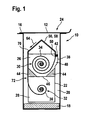
- FIG. 1 shows a known from the prior art outer packaging for receiving a magazine with test elements.
- An outer package 10 for receiving a magazine 22 is usually made of a water vapor-tight material.
- the outer package 10 as shown in FIG. 1 includes a shutter 12 schematically shown here, which is connected at one side 16 with the outer packaging 10.
- the closure 12 shown in the closed state 24 is separated on one side.
- the outer packaging 10 has a first desiccant reservoir 18, which in the illustration according to FIG FIG. 1 lies on the bottom of the outer packaging 10.
- the first desiccant supply 18 may be provided both in powder form, wherein the powder may be embedded in a bag.
- the magazine 22 In a cavity 20 of the outer package 10 is the magazine 22.
- the magazine 22 has a first magazine part 26 and a second magazine part 28.
- In the first magazine part 26 an unused test element stock 30 is received, while in the second magazine part 28 a spent test element stock 32 is included.
- An opening of the magazine 22 is indicated by reference numeral 48. The opening is closed by means of a spring element 38 and a seal 42 connected to the spring element 38.
- the seal 42 is employed on a magazine-side support 50 of the magazine 22.
- the individual test elements stored on the fresh roll 34 of the unused test element stock 30 are guided around the outside of the housing of the magazine 22 by means of a conveyor belt and pass through the opening 48.
- the spent test element is wound on the used roll 36 in the second magazine part 38 of the magazine 22.
- a second desiccant reservoir 44 is received in the first magazine part 26 of the magazine 22 in the first magazine part 26 of the magazine 22 .
- the first magazine part 26 and the second magazine part 28 are separated by a partition 46.
- the second desiccant reservoir 44 stored in the first magazine part 26 serves to dehumidify the unused test element reservoir 30.
- FIG. 2 The representation according to FIG. 2 is shown in enlarged scale representation of the opening of the magazine.
- the seal 42 which is acted upon by the spring element 38, employed on the magazine-side support 50. Due to the elastic properties of the sealing element 42, a contact side 52 of the seal 42 defines, as in FIG. 2 shown, to a conveyor belt 56 at. Thus, the opening 48 of the magazine 22 is reduced to a residual leakage enabling minimum size.
- the residual leakage that can occur through the opening 48 in the active state 42 is due to gussets 54, which result in addition to a conveyor belt 46 - to give an example of a test element carrier - due to the limited deformability of the seal 42.
- the gussets 54 result in different geometries depending on the contact pressure generated by the spring element 38 and depending on the aging of the elastic sealing material of the seal 42.
- the test element transporting conveyor belt 56 is pressed against the magazine-side support 50.
- Figure 2.1 shows a schematic representation of a side view of the in FIG. 2 illustrated conveyor belt.
- FIGS. 1 to 2.1 described embodiment of a repackaging system prevents due to the employment of the seal 42 to the magazine-side pad 50, a contribution to the drying of the recorded and consumed inside the magazine 22 test element stock 30, since the opening 48 - FIG. 2 shown - is reduced to a minimum.
- only the second desiccant reservoir 44 is effective for drying the unused test element stock 30 in the first magazine part 26.
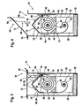
- FIG. 3 shows the repackaging system according to the present invention in the closed state.
- the repackaging system includes the overwrap 10 while the closure 12 is in the closed position 24.
- the closure 12 is connected to the articulation point 16 with the water vapor-tight outer packaging 10.
- both the first desiccant reservoir 18 and the magazine 22 are received.
- the magazine 22 is divided by the partition 46 into the first magazine part 26 and the second magazine part 28.
- the unused test element supply 30 is received in the form of the fresh reel 34, while in the second magazine part 28 the spent test element supply 32 is in the form of a used reel 36.
- the test elements 58 are shown in the illustration FIG.
- the spacer 88 may include a first portion 90 and a second portion 92, which is preferably made of a porous, a water vapor diffusion permitting material.
- the second portion 92 of the spacer / spacer 88 may be in the form of a porous band, a nonwoven, a thread structure, or the like.
- the spacer / spacer 88 may also be a ramp-shaped elevation, a wedge, a cylinder, a block or drgl. Be formed, also the second portion 92 of the spacer / spacer 88 in the form of a band with an opening so be formed for example a hole, a slot or a number of slots.
- the spacer / spacer 88 or its second section 92 is preferably made of a chemically inactive material.
- This material can due to its material properties enable a water vapor diffusion, on the other hand can by the above enumerated variants with respect to the geometry of the spacer / spacer 88 and its second portion 92 in the form of a band with an opening, be it holes, slots, slit or drgl. or by mistake with a wedge, a ramp, a cylinder or drgl. A diffusion of water vapor from the interior of the magazine 22 in the sealed outer packaging 10 are made possible.
- the sealing point 42 assumes a deactivated state 96. This means that the opening 48 in the region of the seal 42 and the outer side 70 of the magazine 22 is open due to the spacer / spacer 88 inserted into it.
- the deactivated state 96 of the seal 42 there is therefore a connection between the second desiccant reservoir 44 accommodated in the first magazine part 26 and the first desiccant reservoir 18, which is located in the hollow space 20 of the outer packaging 10 designed to be water vapor-tight.
- test element supply 30 stored and used in the first magazine part 26 can be dehumidified not only by the second desiccant reservoir 44 within the magazine 22, but also by the first desiccant reservoir 18 provided in the outer packaging 10.
- the closure 12 of the outer package 10 remains in the closed position 24
- one end of the spacer / spacer 88 projects into the opening 48 and enlarges it such that the first desiccant reservoir 18 in the cavity 20 of the outer package 10 during the dehumidification of the unused test element supply 30 of the magazine 22 participates. This can be achieved that in the closed state of the outer packaging according to FIG.
- the second desiccant reservoir 44 within the first magazine portion 26 of the magazine 22 has a smaller manufacturing bias with respect to one Moisture loading has when the outer package 10 is opened and thus the first desiccant reservoir 18 is no longer effective.
- either the amount of the second desiccant reservoir 44 stored in the first magazine section 26 can be reduced with otherwise identical conditions, so that the magazine 22 can be designed to be smaller overall or with an identical amount of the second desiccant reservoir 44, the durability of the unused test element stock 30 can be increased the preload of the second desiccant reservoir 44 has become smaller.
- the representation according to FIG. 4 is the repackaging system as shown in FIG. 3 to be removed when opened.
- FIG. 4 the closure 12 of the outer package 10, which is impermeable to water vapor, is opened, indicated by reference numeral 66.
- the spacer / spacer 88 which is connected to the closure 12 at the connection point 94, emerges from the opening 48, in particular from the region between the seal 42 and the magazine-side pad 50, pulled out.
- the seal 42 now assumes its activated state 98 and seals the first part 26 of the magazine 22, in which the unused test element supply 30 is contained.
- the spacer / spacer 88 takes its in FIG. 4 shown position.
- the spacer / spacer 88 Since the second portion 92 of the spacer / spacer 88 is no longer between the seal 42 and the magazine-side support 50, the opening 48 between the seal 42 and the magazine-side support 50 resumes its original size, due to the biasing force of the leaf spring 40 executable spring element 38.
- the spacer / spacer 88 may not be connected to the closure 12 in a further embodiment of the underlying idea of the invention. In this case, the spacer / spacer 88 can be manually pulled out of the opening 48 on the magazine 22 by the user after opening the outer packaging 10. By this manual intervention of the user is also carried over a transfer of the seal 42 from its deactivated state 96 in its activated state 48.
- the seal 42 ensures that contained in the magazine 22 supply of test elements 48 sealed against the environment.
- the magazine 22 is removed from the outer package 10 with the unused test element stock 30 received therein.
- the dehumidification of the unused test element stock 30 is carried out after opening the water vapor-tight outer packaging 10 now by the second, recorded in the first magazine part 26 desiccant reservoir 44, the in may be present in the form of a desiccant body 82 or in powder filled form.
- the second desiccant reservoir 44 Due to the dehumidification of the unused test element stock 30 by the first desiccant reservoir 18 and the second desiccant reservoir 44 in the closed state 24 due to the inactive state 96 of the seal 42, the second desiccant reservoir 44, after opening the outer package 10 as shown in FIG FIG. 4 a smaller preload, whereby the durability (on-board stability) of the recorded in the first magazine portion 26 of the magazine 22 unused test element stock 30 can be increased. Due to the lower preload of the second desiccant reservoir 44 in the magazine 22, on the one hand, the amount of second desiccant reservoir 44 to be introduced into the magazine 22 can now be reduced, as a result of which its size can be reduced.
Landscapes
- Health & Medical Sciences (AREA)
- Engineering & Computer Science (AREA)
- Biomedical Technology (AREA)
- Life Sciences & Earth Sciences (AREA)
- Physics & Mathematics (AREA)
- Chemical & Material Sciences (AREA)
- Medicinal Chemistry (AREA)
- General Health & Medical Sciences (AREA)
- Molecular Biology (AREA)
- Urology & Nephrology (AREA)
- Biophysics (AREA)
- Food Science & Technology (AREA)
- Optics & Photonics (AREA)
- Analytical Chemistry (AREA)
- Biochemistry (AREA)
- Hematology (AREA)
- General Physics & Mathematics (AREA)
- Immunology (AREA)
- Pathology (AREA)
- Packages (AREA)
- Investigating Or Analysing Biological Materials (AREA)
- Details Of Rigid Or Semi-Rigid Containers (AREA)
- Measurement Of The Respiration, Hearing Ability, Form, And Blood Characteristics Of Living Organisms (AREA)
- Auxiliary Devices For And Details Of Packaging Control (AREA)
Abstract
Description
Die Erfindung bezieht sich auf ein Umverpackungssystem für medizinische Testelemente, die in einem aus der Umverpackung entnehmbaren Magazin aufgenommen sind.The invention relates to a repackaging system for medical test elements, which are accommodated in a removable from the outer packaging magazine.
In einem Magazin aufgenommenes medizinisches Verbrauchsmaterial, wie z. B. Testelemente, die zur Blutzuckermessung zur Laktatmessung oder auch zur Cholesterinbestimmung in Messgeräten verwendet werden, wird in einer z. B. als Umhüllung ausgebildeten Verpackung verpackt, um das medizinische Verbrauchsmaterial vor Umgebungseinflüssen zu schützen. Testelemente für medizinische Zwecke reagieren besonders empfindlich auf Temperaturschwankungen und insbesondere auf Feuchtigkeit. Daher sind Magazine, in welchen im Allgemeinen eine Anzahl von Testelementen aufgenommen ist, in die Umverpackung eingeschweißt, um einen Feuchtigkeitseintritt in die Umverpackung und damit eine Schädigung des in der Umverpackung aufgenommenen Magazins mit den Testelementen gegen eindringende Feuchtigkeit zu verhindern.In a magazine recorded medical supplies, such. B. test elements that are used for blood glucose measurement for lactate measurement or for cholesterol determination in measuring instruments, is in a z. B. wrapped packaging designed to protect the medical supplies from environmental influences. Test elements for medical purposes are particularly sensitive to temperature fluctuations and in particular to moisture. As a result, magazines in which a number of test elements are generally received are welded into the outer packaging in order to prevent moisture from entering the outer packaging and thus damaging the magazine contained in the outer packaging with the moisture-proofing test elements.
Die in der Regel wasserdampfdicht ausgeführte Umverpackung, die zu Verkaufszwecken in einer Verkaufsverpackung aufgenommen ist, enthält einen Trockenmittelvorrat. Auch das Magazin, in welchem die Testelemente aufgenommen sind, enthält einen Trockenmittelvorrat. Der Trockenmittelvorrat im Magazin mit den Testelementen dient dazu, während der Zeitspanne zwischen der Herstellung der Testelemente bis zu deren Verbrauch durch den Anwender die im Magazin enthaltenen Testelemente vor Wasserdampfbeladung zu schützen. Damit kann erreicht werden, dass die Testelemente eine von der Lagerungsdauer unabhängige Haltbarkeit aufweisen, da während dieser Zeitspanne der Trockenmittelvorrat innerhalb des die Testelemente aufnehmenden Magazins einen diffundierenden Wasserdampf aufnimmt und von den im Magazin enthaltenen Testelementen fernhält.The outer packaging, which is generally water-vapor-tight and which is received for sale in a sales packaging, contains a desiccant supply. The magazine in which the test elements are accommodated also contains a desiccant reservoir. The desiccant supply in the magazine with the test elements serves to during the period between the production of the test elements to their consumption by the user to protect the test elements contained in the magazine from water vapor loading. It can thus be achieved that the test elements have a storage life independent of the storage duration, since during this period the desiccant supply within the magazine receiving the test elements absorbs a diffusing water vapor and keeps it away from the test elements contained in the magazine.
Ist das Magazin z. B. kassettenförmig ausgebildet und enthält Wickelspulen für auf einem Transportband aufgenommene Einzeltestelemente, so wird in der Regel in dem Teil, in dem sich die unverbrauchten, in Form einer gewickelten Spule befindenden Testelemente aufgenommen sind, eine Trockenmittelmenge eingebracht. Die Kassette wird nach der Bestückung mit dem Transportband, auf welches die Einzeltestelemente aufgebracht sind, versiegelt und in eine z. B. als Aluminiumtopf ausgebildete Umverpackung eingelegt und zusammen mit einem ebenfalls in die Umverpackung eingebrachten Trockenmittel in der Umverpackung eingeschweißt. Bei geschlossener Umverpackung stellt der darin enthaltene Trockenmittelvorrat während der Lagerung sicher, dass keine Umgebungsfeuchte während der Lagerung auf die Kassette einwirkt und in diese eindringt.Is the magazine z. B. cassette-shaped and contains winding coils for recorded on a conveyor belt single test elements, so a desiccant is usually introduced in the part in which the unconsumed, in the form of a wound coil located test elements are added. The cassette is sealed after the assembly with the conveyor belt, on which the individual test elements are applied, and in a z. B. inserted as an aluminum pot outer packaging and welded together with a likewise introduced into the outer packaging desiccant in the outer packaging. When the outer packaging is closed, the desiccant supply contained therein ensures during storage that no ambient moisture will be absorbed by the cassette during storage.
Von Nachteil bei der oben dargestellten Lösung gemäß des derzeitigen Standes der Technik ist der Umstand, dass beim Herstellungsprozess sowohl das Trockenmittel als auch die Testelemente unvermeidlich mit Wasserdampf belastet werden. Nach Fertigstellung des Magazins, dies bedeutet nach Beladung des Magazins mit einer Anzahl von Testelementen, sind die darin aufgenommenen Testelemente und das im Magazin enthaltene Trockenmittel mit herstellungsbedingter Feuchtigkeit teilbeladen. Dies bedeutet, dass der im Magazin enthaltene Trockenmittelvorrat nur noch eine Restaufnahmekapazität für eindringende Feuchtigkeit hat. Der im Magazin enthaltene Trockenmittelvorrat trocknet zuerst das Innere des Magazins, die noch verbleibende Restaufnahmekapazität des im Magazin enthaltenen Trockenmittelvorrates dient zur Sicherstellung der Haltbarkeit der Testelemente im Magazin.A disadvantage of the above-described solution according to the current state of the art is the fact that in the manufacturing process, both the desiccant and the test elements are inevitably loaded with water vapor. After completion of the magazine, which means after loading the magazine with a number of test elements, the test elements contained therein and the desiccant contained in the magazine are partially laden with production-related moisture. This means that the desiccant supply contained in the magazine has only a residual capacity for penetrating moisture. The desiccant supply contained in the magazine first dries the interior of the magazine, the remaining residual capacity of the desiccant store contained in the magazine serves to ensure the durability of the test elements in the magazine.
Der Erfindung liegt die Aufgabe zugrunde, ein Umverpackungssystem für medizinische Testelemente, bereitzustellen, welches die Haltbarkeit (On-Board-Stability) der Testelemente erhöht.The invention has for its object to provide a repackaging system for medical test elements, which increases the durability (on-board stability) of the test elements.
Der erfindungsgemäß vorgeschlagenen Lösung folgend, kann während der Lagerung des die Testelemente aufnehmenden Magazins in der Umverpackung eine Verbindung zwischen dem Trockenmittelvorrat in der Umverpackung und dem Trockenmittelvorrat im die Testelemente aufnehmenden Magazin geschaffen werden, welche, solange die Umverpackung geschlossen ist, eine Verbindung zwischen dem in der Umverpackung aufgenommenen Trockenmittel und dem im Magazin enthaltenen Trockenmittel herstellt. Die Verbindung zwischen dem Trockenmittelvorrat der Umverpackung und dem im Magazin enthaltenen Trockenmittelvorrat kann z. B. durch einen Spacer oder Abstandhalter geschaffen werden, der einerseits mit der Umverpackung verbunden ist, und welcher andererseits zwischen einer Dichtung und dem Gehäuse des in der Umverpackung aufgenommenen Magazins mit den Testelementen liegt.Following the proposed solution according to the invention, during the storage of the test elements receiving magazine in the outer packaging, a connection between the desiccant reservoir in the outer packaging and the desiccant reservoir in the test elements receiving magazine are created, which, as long as the outer packaging is closed, a connection between the in the desiccant recorded desiccant and the desiccant contained in the magazine produces. The connection between the desiccant supply of the outer packaging and the desiccant supply contained in the magazine can, for. B. are created by a spacer or spacer, which is on the one hand connected to the outer packaging, and which on the other hand lies between a seal and the housing of the recorded in the outer packaging magazine with the test elements.
Durch den Spacer oder Abstandhalter, der z. B. als ein Band mit einem porösen Abschnitt als eine Gewebestruktur, als ein Vlies oder ein Fadengeflecht ausgeführt sein kann, wird eine Öffnung zwischen der Dichtung des Magazins und dem Innenraum der Umverpackung geschaffen, die so lange existiert, solange das die Testelemente aufnehmende Magazin in der wasserdampfdichten Umhüllung der Umverpackung aufgenommen ist.By the spacer or spacer, the z. B. as a band having a porous portion as a fabric structure, as a non-woven or a thread mesh can be made, an opening between the seal of the magazine and the interior of the outer packaging is created, which exists as long as the test elements receiving magazine in the water vapor-tight envelope of the outer packaging is added.
Solange das Magazin mit dem darin aufgenommenen Trockenmittelvorrat in der Umverpackung verbleibt, kann über die mittels des Spacers beziehungsweise Abstandhalters erweiterte Öffnung der in der Umverpackung aufgenommene Trockenmittelvorrat Feuchtigkeit aus dem Magazin heraus mit aufnehmen. In der Regel ist der in der Umverpackung aufgenommene Feuchtmittelvorrat wesentlich größer als der Feuchtmittelvorrat, der im die Testelemente enthaltenden Magazin aufgenommen ist. Durch die erfindungsgemäß vorgeschlagene Lösung kann der in der Umverpackung aufgenommene Trockenmittelvorrat dazu herangezogen werden, einerseits die herstellungsbedingte Feuchtigkeitsbeladung der im Magazin enthaltenen Testelemente herabzusetzen und lagerungszeitbedingt eindiffundierende Feuchtigkeit in die Umverpackung zu absorbieren.As long as the magazine with the desiccant stored therein remains in the outer packaging, moisture can be taken out of the magazine via the opening of the desiccant reservoir received in the outer packaging via the spacer or spacer. As a rule, the dampening solution supply received in the outer packaging is substantially larger than the dampening solution supply which is accommodated in the magazine containing the test elements. By inventively proposed solution, the desiccant stored in the outer packaging can be used to reduce the one hand, the production-related moisture content of the test elements contained in the magazine and absorb storage moisture due to storage time in the outer packaging.
In einem bevorzugten Ausführungsbeispiel wird, sobald die Umverpackung geöffnet wird, die zuvor durch den Spacer oder Abstandhalter zwischen dem Gehäuse des Magazins und der Dichtung und dem in der Umverpackung enthaltenen Trockenmittelvorrat geschaffene Öffnung auf eine fertigungstechnisch bedingte Restgröße verschlossen. In diesem bevorzugten Ausführungsbeispiel der vorliegenden Erfindung wird beim Öffnen der Umverpackung der Umverpackung der mit der Umverpackung verbundene Spacer beziehungsweise Abstandhalter aus der Öffnung zwischen der Dichtung und dem Magazin herausgezogen, wodurch die Öffnung ihre Restgröße annimmt. Wird der Spacer beziehungsweise Abstandhalter aus einem porösen, eine Wasserdampfdiffusion ermöglichenden Material gefertigt, so vermag der in der Umverpackung aufgenommene Trockenmittelvorrat Wasserdampf aus dem Inneren des Magazins zu ziehen, der über den zwischen dem Gehäuse des Magazins mit der Dichtung aufgenommenen Spacer beziehungsweise Abstandhalter im Hohlraum der Umverpackung durch den dort enthaltenen größeren Trockenmittelvorrat absorbiert werden kann. In einem weiteren Ausführungsbeispiel des der Erfindung zugrunde liegenden Gedankens lässt sich der Spacer beziehungsweise der Abstandhalter nach dem Öffnen der Umverpackung manuell aus der Öffnung zwischen der Dichtung und dem Magazin herausziehen, so dass die der Öffnung des Magazins zugeordnete Dichtung von ihrer inaktiven Position in ihre aktive, d.h. Dichtposition überführt wird. Gemäß dieser Ausführungsvariante erfolgt das Überführen der Dichtung von ihrem inaktiven Zustand im geschlossenen Zustand der Umverpackung in ihre aktive Position nach dem Öffnen der Umverpackung manuell durch den Benutzer.In a preferred embodiment, as soon as the outer packaging is opened, the opening previously created by the spacer or spacer between the housing of the magazine and the seal and the desiccant reservoir contained in the outer packaging is closed to a production-related residual size. In this preferred embodiment of the present invention is when opening the outer packaging of the outer packaging of the connected to the outer packaging spacer or spacer pulled out of the opening between the seal and the magazine, whereby the opening assumes its residual size. If the spacer or spacers made of a porous, a water vapor diffusion permitting material, so absorbed in the outer package desiccant can draw water vapor from the inside of the magazine, which on the recorded between the housing of the magazine with the seal spacers or spacers in the cavity Outer packaging can be absorbed by the larger desiccant supply contained therein. In a further embodiment of the invention underlying the idea, the spacer or the spacer after opening the outer packaging can be manually pulled out of the opening between the seal and the magazine, so that the opening of the magazine associated seal from its inactive position in their active , ie sealing position is transferred. According to this embodiment, the transfer of the seal from its inactive state takes place in the closed state of the outer packaging in its active position after opening the outer packaging manually by the user.
Nach der Entnahme des Magazins aus der Umverpackung stellt der im Inneren des Magazins enthaltene Trockenmittelvorrat unter Berücksichtigung einer Restleckage und unter Berücksichtigung der Umgebungsbedingungen die Haltbarkeit der im Magazin enthaltenen Testelemente sicher.After the magazine has been removed from the outer packaging, the desiccant supply contained inside the magazine ensures the durability of the test elements contained in the magazine, taking into account a residual leakage and taking into account the ambient conditions.
Der mit der vorgeschlagenen Lösung einhergehende Vorteil ist darin zu erblicken, dass der im Magazin enthaltene Trockenmittelvorrat ab dem Zeitpunkt der Entnahme des Magazins aus der Umverpackung eine kleinere Wasserdampfbeladung, die herstellungsbedingt ist, aufweist. Dies hat zur Folge, dass bei Einsatz der erfindungsgemäß vorgeschlagenen Lösung entweder die Trockenmittelmenge im Magazin bei sonst identischen Bedingungen geringer ausgelegt werden kann, was eine Verkleinerung der Baugröße des die Testelemente aufnehmenden Magazins zur Folge hat, oder dass bei identischer in das Magazin eingebrachte Trockenmittelmenge die Haltbarkeit der darin aufgenommenen Testelemente erheblich gesteigert werden kann.The advantage associated with the proposed solution is to be seen in the fact that the desiccant supply contained in the magazine from the time of removal of the magazine from the outer packaging, a smaller water vapor load, which is due to manufacturing has. This has the consequence that when using the proposed solution according to the invention either the amount of desiccant in the magazine under otherwise identical conditions can be made smaller, resulting in a reduction in size of the test elements receiving magazine result, or that with identical introduced into the magazine desiccant the Durability of the recorded therein test elements can be significantly increased.
Anhand der Zeichnung wird die Erfindung nachstehend eingehender beschrieben.With reference to the drawing, the invention will be described below in more detail.
Es zeigt:
- Figur 1
- ein Umverpackungssystem gemäß des Standes der Technik im geschlossenen Zustand mit in der Umverpackung aufgenommenem Magazin für Testelemente,
- Figur 2
- eine Detailansicht der Öffnung des Magazins des zwischen Magazingehäuse und Dichtung geführten Transportbandes,
- Figur 2.1
- eine schematische Darstellung des Transportbandes mit in Seitenansicht nicht maßstabsgerecht wiedergegebenem Einzel-Testelement,
- Figur 3
- die Darstellung des mit der Umverpackung verbundenen Spacers oder Abstandhalters zur Deaktivierung einer Dichtung am Gehäuse des Magazins bei verschlossener Umverpackung und
- Figur 4
- die geöffnete Umverpackung mit aus der Öffnung entferntem Spacer oder Abstandhalter.
- FIG. 1
- a wrap-around system according to the prior art in the closed state with a magazine for test elements accommodated in the outer packaging,
- FIG. 2
- a detailed view of the opening of the magazine of the guided between the magazine housing and seal conveyor,
- Figure 2.1
- a schematic representation of the conveyor belt with side view not to scale reproduced individual test element,
- FIG. 3
- the representation of the associated with the outer packaging spacer or spacer for deactivating a seal on the housing of the magazine with closed outer packaging and
- FIG. 4
- the opened outer packaging with removed from the opening spacer or spacer.
Unter Magazin wird nachfolgend ein Aufnahrneelement verstanden, in welchem eine Anzahl von Testelementen aufgenommen ist. Das Magazin kann kassettenförmig ausgestaltet sein, wobei der Vorrat von Testelementen z. B. in Form von Wickelspulen mit einer Spule für unverbrauchte Testelemente und einer Spule für verbrauchte Testelemente ausgestattet ist. Das Magazin kann auch stapelförmig ausgebildet sein, wobei einzelne Testelemente, so z. B. in Streifenform, in vertikaler, horizontaler oder in relativ zueinander geneigter Anordnung aufgenommen sein können. Das Magazin kann auch als scheibenförmiger Körper beschaffen sein, an dessen Umfang einzelne Testelemente in Schlitzen aufgenommen sind, wobei ein Antrieb das scheibenförmig konfigurierte Magazin von Testelement zu Testelement weiterschaltet.In the following, a magazine is understood to mean a recording element in which a number of test elements are received. The magazine can be designed cassette-shaped, wherein the supply of test elements z. B. in the form of winding coils with a coil for unused test elements and a coil for spent test elements is equipped. The magazine can also be stacked, with individual test elements, such. B. in strip form, in vertical, horizontal or relative to each other inclined arrangement can be added. The magazine can also be designed as a disc-shaped body, on the circumference of individual test elements are received in slots, wherein a drive advances the disk-shaped magazine configured test element to test element.
Unter Testelementen wird nachfolgend ein medizinisches Verbrauchsmaterial verstanden, welches z. B. in Streifenform im Magazin bevorratet ist und welches der Bestimmung eines Analyten in einer menschlichen Körperflüssigkeit, wie z. B. Blutzucker, Laktat oder Cholesterin und dergleichen, dient. Unter Öffnung wird nachfolgend eine Austrittsöffnung des z. B. in Teststreifenform vorliegenden medizinischen Verbrauchsmaterials aus dem Magazin verstanden, die z. B. als eine mittels einer an das Gehäuse des Magazins angestellten Dichtung oder als Längsschlitz mit Dichtlippen ausgebildet sein kann, um einen unerwünschten Feuchtigkeitseintritt in das Innere des die Testelemente aufnehmenden Magazins zu verhindern.Under test elements is understood below a medical consumables, which, for. B. is stored in strip form in the magazine and which of the determination of an analyte in a human body fluid such. As blood sugar, lactate or Cholesterol and the like, serves. Under opening below an outlet opening of the z. B. understood in test strip form medical consumables from the magazine, the z. B. may be formed as a means of a hired to the housing of the magazine seal or as a longitudinal slot with sealing lips to prevent unwanted ingress of moisture into the interior of the test elements receiving magazine.
Unter Trockenmittelvorrat wird nachfolgend ein Trockenmittelsubstrat verstanden, welches der Aufnahme von Wasserdampf dient. Das Trockenmittel kann dabei in Pulverform vorliegen und in Beuteln, die in das Innere des Magazins oder in das Innere der Umverpackung eingelassen sind. Ferner kann das Trockenmittel als Trockenmittelkörper ausgebildet sein, welcher ein integraler Bestandteil des die Testelemente aufnehmenden Magazins ist.Under desiccant supply is hereinafter understood a desiccant substrate, which serves to absorb water vapor. The desiccant may be present in powder form and in bags that are embedded in the interior of the magazine or in the interior of the outer packaging. Furthermore, the desiccant may be formed as a desiccant body, which is an integral part of the magazine receiving the test elements.
Eine Umverpackung 10 zur Aufnahme eines Magazins 22 wird in der Regel aus einem wasserdampfdichten Material hergestellt. Die Umverpackung 10 gemäß der Darstellung in
In einem Hohlraum 20 der Umverpackung 10 befindet sich das Magazin 22. Das Magazin 22 weist einen ersten Magazinteil 26 und einen zweiten Magazinteil 28 auf. Im ersten Magazinteil 26 ist ein unverbrauchter Testelementvorrat 30 aufgenommen, während im zweiten Magazinteil 28 ein verbrauchter Testelementevorrat 32 aufgenommen ist. So kann z. B. bei einer kassettenförmigen Konfiguration des Magazins 22 der unverbrauchte Testelementvorrat 30 in Form eines Frischwickels 34 im ersten Magazinteil 26 aufgenommen sein, während im zweiten Magazinteil 28 der verbrauchte Testelementvorrat 32 in Form eines Gebrauchtwickels 36 aufgenommen ist. Eine Öffnung des Magazins 22 ist durch Bezugszeichen 48 gekennzeichnet. Die Öffnung wird mittels eines Federelementes 38 und einer mit dem Federelement 38 verbundenen Dichtung 42 verschlossen. In der Darstellung gemäß
Im ersten Magazinteil 26 des Magazins 22 ist ein zweiter Trockenmittelvorrat 44 aufgenommen. Der erste Magazinteil 26 und der zweite Magazinteil 28 sind durch eine Trennwand 46 voneinander getrennt. Der im ersten Magazinteil 26 bevorratete zweite Trockenmittelvorrat 44 dient der Entfeuchtung des unverbrauchten Testelementvorrates 30.In the
Der Darstellung gemäß
Im in
Aus der Darstellung gemäß
Die in den
Das Umverpackungssystem umfasst die Umverpackung 10, während Verschluss 12 sich in der Schließposition 24 befindet. Der Verschluss 12 ist an der Anlenkstelle 16 mit der wasserdampfdicht ausgeführten Umverpackung 10 verbunden. Im Hohlraum 20 der Umverpackung 10 sind sowohl der erste Trockenmittelvorrat 18 als auch das Magazin 22 aufgenommen. Das Magazin 22 ist durch die Trennwand 46 in den ersten Magazinteil 26 und den zweiten Magazinteil 28 unterteilt. Im ersten Magazinteil 26 ist der unverbrauchte Testelementvorrat 30 in Form des Frischwickels 34 aufgenommen, während sich im zweiten Magazinteil 28 der verbrauchte Testelementvorrat 32 in Form eines Gebrauchtwickels 36 befindet. Die Testelemente 58 sind in der Darstellung gemäß
Aus der Darstellung gemäß
Aufgrund des sich in die Öffnung 48 des Magazins 22 erstreckenden zweiten Abschnitts 92 des Spacers/Abstandhalters 88 nimmt die Dichtungsstelle 42 einen deaktivierten Zustand 96 ein. Dies bedeutet, dass die Öffnung 48 im Bereich der Dichtung 42 und der Außenseite 70 des Magazins 22 aufgrund des in diese eingeführten Spacers/Abstandhalters 88 geöffnet steht. Im deaktivierten Zustand 96 der Dichtung 42 besteht demnach eine Verbindung des im ersten Magazinteil 26 aufgenommenen zweiten Trockenmittelvorrats 44 und dem ersten Trockenmittelvorrat 18, der sich im Hohlraum 20 der wasserdampfdicht ausgeführten Umverpackung 10 befindet. Dadurch wird erreicht, dass der im ersten Magazinteil 26 bevorratete und verbrauchte Testelementvorrat 30 nicht nur durch den zweiten Trockenmittelvorrat 44 innerhalb des Magazins 22, sondern auch durch den in der Umverpackung 10 vorgesehenen ersten Trockenmittelvorrat 18 entfeuchtet werden kann. Solange der Verschluss 12 der Umverpackung 10 in der Schließposition 24 bleibt, ragt ein Ende des Spacers/Abstandhalters 88 in die Öffnung 48 und vergrößert diese derart, dass der erste Trockenmittelvorrat 18 im Hohlraum 20 der Umverpackung 10 bei der Entfeuchtung des unverbrauchten Testelementvorrats 30 des Magazins 22 mitwirkt. Damit kann erreicht werden, dass im verschlossenen Zustand des Umverpackungssystems gemäß
Der Darstellung gemäß
In
Aufgrund der im geschlossenen Zustand 24 durch den inaktiven Zustand 96 der Dichtung 42 erfolgenden Entfeuchtung des unverbrauchten Testelementvorrates 30 durch den ersten Trockenmittelvorrat 18 und den zweiten Trockenmittelvorrat 44 weist der zweite Trockenmittelvorrat 44 nach Öffnen der Umverpackung 10 gemäß der Darstellung in
- 1010
- Umverpackungoverpack
- 1212
- Verschlussshutter
- 1414
- Entnahmeöffnungremoval opening
- 1616
- Anlenkstelle VerschlussAnlenkstelle closure
- 1818
- erster Trockenmittelvorratfirst desiccant supply
- 2020
-
Hohlraum Umverpackung 10Cavity
outer packaging 10 - 2222
- Magazinmagazine
- 2424
-
Schließposition Verschluss 12
Closing position closure 12 - 2626
- erster Magazinteilfirst magazine part
- 2828
- zweiter Magazinteilsecond magazine part
- 3030
-
unverbrauchter
Testelementvorratunspent
Test element stock - 3232
-
verbrauchter
Testelementvorratconsumed
Test element stock - 3434
- Frischwickelfresh wrap
- 3636
- GebrauchtwickelUsed wrapping
- 3838
- Federelementspring element
- 4040
- Blattfederleaf spring
- 4242
- Dichtungpoetry
- 4444
- zweiter Trockenmittelvorratsecond desiccant supply
- 4646
- Trennwandpartition wall
- 4848
- Öffnungopening
- 5050
- magazinseitige AuflageMagazine-side edition
- 5252
- Kontaktseite DichtungContact side seal
- 5454
- Zwickelgore
- 5656
- Transportbandconveyor belt
- 5858
- Testelementtest element
- 6060
- Dicke TransportbandThick conveyor belt
- 6262
-
Dicke Transportband +
TestelementThick conveyor belt +
test element - 6464
- Förderrichtungconveying direction
- 6666
- Offenstellungopen position
- 7070
- Außenseite MagazinOutside magazine
- 7272
- TransportbandpfadConveyor path
- 8888
- Spacer/AbstandhalterSpacer / spacers
- 9090
- erster Abschnitt Spacerfirst section spacer
- 9292
- zweiter Abschnitt Spacersecond section spacer
- 9494
-
Verbindungsstelle Verschluss 12
Connection point closure 12 - 9696
-
deaktivierter Zustand
Dichtung 42deactivated state
Seal 42 - 9898
-
aktivierter Zustand Dichtung
42activated state seal
42
Claims (21)
- Container system for medical test elements (58), with a container (10) accommodating a first supply of dry substance (18) and a magazine (22) with an unused supply of test element (30), characterised in that when the container (10) is in the closed state (24), the first supply of dry substance (18) in the container (10) acts on the interior of the magazine (22) via a connection (96) permitting a diffusion of water vapour which is closed when the container (10) of the magazine (22) is opened.
- Container system as claimed in claim 1, characterised in that the magazine (22) contains a second supply of dry substance (44).
- Container system as claimed in claim 1, characterised in that the magazine (22) has a seal (42) which assumes a deactivated state (96) permitting a diffusion of water vapour into the container (10) when the container (10) is in the closed state (24).
- Container system as claimed in claim 3, characterised in that the seal (42) is acted on by a spring element (38).
- Container system as claimed in claims 3 or 4, characterised in that the seal (42) fits into a cut-out (76) of the magazine (22) or is attached to the spring element (38).
- Container system as claimed in claim 3, characterised in that a spacer/distance piece (88) is provided on the container (10), which holds the seal (42) in its deactivated state (96) when the container (10) is in the closed state (24).
- Container system as claimed in claim 6, characterised in that the spacer/ distance piece (88) has a first portion (90) and a second portion (92) and the second portion (92) is made from a material which permits a diffusion of water vapour or its geometry permits a diffusion of water vapour.
- Container system as claimed in claim 7, characterised in that the second portion (92) is provided in the form of a porous tape, non-woven material, yarn structure or woven fabric.
- Container system as claimed in claim 6, characterised in that the first portion (90) of the spacer/distance piece (88) is secured to a connection point (94) on the part (12) of the container (10) intended to be opened.
- Container system as claimed in claim 1, characterised in that the first and the second supply of dry substance (18, 44) are provided in the form of dry substance bodies in the container (10) and in the magazine (22).
- Container system as claimed in claim 1, characterised in that the container (10) is made from a material that is impervious to water vapour.
- Container system as claimed in claim 3, characterised in that the seal (42) holds open an enlarged cross-section of an opening (48) to the unused supply of test element (30) in the magazine (22) in the deactivated state (96).
- Container system as claimed in claim 3, characterised in that the seal (42) is transferred to an activated state (98) when the container (10) is opened.
- Container system as claimed in claim 13, characterised in that the seal (42) is positioned on a part of the unused supply of test element (30) disposed in the opening (48) in the activated state (98).
- Container system as claimed in claim 1, characterised in that the unused supply of test element (30) is accommodated in a cassette-type magazine (22) in the form of a fresh reel (34) of a conveyor strip (56) with test elements (58).
- Container system as claimed in claim 1, characterised in that the first supply of dry substance (18) in the cavity (20) of the container (10) is disposed lying opposite an opening (48) in the magazine (22).
- Container system as claimed in claim 1, characterised in that the second supply of dry substance (44) is contained between a first part (26) of the magazine (22) which is separated from a second part (28) of the magazine (22).
- Use of the container system as claimed in one of claims 1 to 17 for accommodating an unused supply of test element (30), in particular test elements (58) for determining blood sugar, cholesterol, lactate values, bilirubin, triglycerides, amylase, uric acid, urea, potassium, HDL cholesterol or creatine kinase.
- Method of extending the shelf life of medical test elements (58) accommodated in a container (10), comprising the following method steps:a) when the container (10) is in the closed state (24), a connection (96) permitting a diffusion of water vapour is established between a first supply of dry substance (18) contained in the container (10) and the interior of a magazine (22) accommodating the test elements (58),b) when the container (10) is opened or after opening the container (10), the connection (96) permitting a diffusion of water vapour is closed.
- Method as claimed in claim 19, characterised in that the connection (96) permitting a diffusion of water vapour is closed by opening (66) a closure (12) in method step (b).
- Method as claimed in claim 19, characterised in that the connection (96) permitting a diffusion of water vapour is manually closed in method step (b).
Priority Applications (10)
| Application Number | Priority Date | Filing Date | Title |
|---|---|---|---|
| EP05028293A EP1801583B1 (en) | 2005-12-23 | 2005-12-23 | Container for medical consumables, with desiccant compartment |
| DE502005005426T DE502005005426D1 (en) | 2005-12-23 | 2005-12-23 | Container for medical supplies, with desiccant stock |
| AT05028293T ATE408823T1 (en) | 2005-12-23 | 2005-12-23 | CONTAINER FOR MEDICAL CONSUMABLES, WITH DESICTANT STORAGE |
| ES05028293T ES2314551T3 (en) | 2005-12-23 | 2005-12-23 | CONTAINER FOR CONSUMABLE MEDICAL MATERIAL, WITH A DESECTIVE BEHAVIOR. |
| CA2568320A CA2568320C (en) | 2005-12-23 | 2006-11-16 | Outer packaging system for medical consumables |
| EP06126118A EP1801585A1 (en) | 2005-12-23 | 2006-12-14 | Container for medical consumables, with desiccant compartment |
| US11/612,889 US7975842B2 (en) | 2005-12-23 | 2006-12-19 | Outer packaging system for medical consumables |
| JP2006344976A JP4607853B2 (en) | 2005-12-23 | 2006-12-21 | Exterior system for medical consumables |
| CN2006101701305A CN1985787B (en) | 2005-12-23 | 2006-12-22 | Container for medical consumables |
| HK07113403.7A HK1107669A1 (en) | 2005-12-23 | 2007-12-07 | Outer packaging system for medical consumables |
Applications Claiming Priority (1)
| Application Number | Priority Date | Filing Date | Title |
|---|---|---|---|
| EP05028293A EP1801583B1 (en) | 2005-12-23 | 2005-12-23 | Container for medical consumables, with desiccant compartment |
Publications (2)
| Publication Number | Publication Date |
|---|---|
| EP1801583A1 EP1801583A1 (en) | 2007-06-27 |
| EP1801583B1 true EP1801583B1 (en) | 2008-09-17 |
Family
ID=36406220
Family Applications (1)
| Application Number | Title | Priority Date | Filing Date |
|---|---|---|---|
| EP05028293A Not-in-force EP1801583B1 (en) | 2005-12-23 | 2005-12-23 | Container for medical consumables, with desiccant compartment |
Country Status (9)
| Country | Link |
|---|---|
| US (1) | US7975842B2 (en) |
| EP (1) | EP1801583B1 (en) |
| JP (1) | JP4607853B2 (en) |
| CN (1) | CN1985787B (en) |
| AT (1) | ATE408823T1 (en) |
| CA (1) | CA2568320C (en) |
| DE (1) | DE502005005426D1 (en) |
| ES (1) | ES2314551T3 (en) |
| HK (1) | HK1107669A1 (en) |
Families Citing this family (7)
| Publication number | Priority date | Publication date | Assignee | Title |
|---|---|---|---|---|
| CA3161026A1 (en) | 2014-09-17 | 2016-03-24 | Canary Medical Inc. | Devices, systems and methods for using and monitoring medical devices |
| CA3017932A1 (en) | 2016-03-23 | 2017-09-28 | Canary Medical Inc. | Implantable reporting processor for an alert implant |
| DE112018002760T5 (en) * | 2017-06-02 | 2020-02-20 | Brandon Bransgrove | DIAGNOSTIC TEST UNIT FOR ANALYZING BODY LIQUID |
| JP7035763B2 (en) * | 2018-04-25 | 2022-03-15 | セイコーエプソン株式会社 | Packing body, manufacturing method of packing body, and manufacturing method of liquid discharge device |
| CN109878862A (en) * | 2019-01-22 | 2019-06-14 | 安徽中科都菱商用电器股份有限公司 | Blood platelet constant temperature shakes storage box |
| US11690680B2 (en) | 2019-03-19 | 2023-07-04 | Mako Surgical Corp. | Trackable protective packaging for tools and methods for calibrating tool installation using the same |
| US11395711B2 (en) | 2019-06-05 | 2022-07-26 | Stryker European Operations Limited | Packaging systems and methods for mounting a tool on a surgical device using the same |
Family Cites Families (19)
| Publication number | Priority date | Publication date | Assignee | Title |
|---|---|---|---|---|
| US2583001A (en) * | 1949-04-01 | 1952-01-22 | Lloyd E Magers | Ground inserted cemetery vase |
| US2533806A (en) * | 1949-07-06 | 1950-12-12 | Harry R Holzapfel | Bottle |
| US3918578A (en) * | 1974-04-01 | 1975-11-11 | Multiform Desiccant Products I | Desiccant end cap |
| US4146277A (en) * | 1978-06-29 | 1979-03-27 | Santoro Dario S | Desiccant cap |
| EP0167783B1 (en) * | 1984-06-28 | 1988-10-19 | ZELLER PLASTIK Koehn, Gräbner & Co. | Closure device for a container and such a container |
| DE3519296A1 (en) * | 1984-06-28 | 1986-01-09 | Zeller Plastik Koehn, Gräbner & Co, 5583 Zell | Closure device for the removal aperture of a container and associated container |
| DE3715938A1 (en) | 1987-05-13 | 1988-11-24 | Boehringer Mannheim Gmbh | CONTAINER FOR TEST STRIP |
| US5279025A (en) * | 1990-07-13 | 1994-01-18 | Kinast Leonard L | Method of securing a cap assembly to a radiator |
| GB9411626D0 (en) * | 1994-06-10 | 1994-08-03 | Smithkline Beecham Plc | Package |
| NZ291443A (en) * | 1994-08-05 | 1998-07-28 | Smithkline Beecham Plc | Container with puncturable seal carrying desiccant polymer |
| US5510266A (en) * | 1995-05-05 | 1996-04-23 | Bayer Corporation | Method and apparatus of handling multiple sensors in a glucose monitoring instrument system |
| DE19819407A1 (en) | 1998-04-30 | 1999-11-11 | Hendrik Priebs | Cassette for disposable strip with test spots for e.g. blood sugar measurement |
| US6709493B2 (en) * | 2001-03-26 | 2004-03-23 | Gore Enterprise Holdings, Inc. | Device for reducing the presence of moisture within an enclosure containing a heat source |
| WO2003089917A1 (en) * | 2002-04-19 | 2003-10-30 | Matsushita Electric Industrial Co., Ltd. | Biosensor cartridge and biosensor dispensing device |
| JP4439198B2 (en) * | 2002-04-19 | 2010-03-24 | パナソニック株式会社 | Biosensor cartridge and biosensor dispensing device |
| US7303726B2 (en) * | 2002-05-09 | 2007-12-04 | Lifescan, Inc. | Minimal procedure analyte test system |
| DE10353445B4 (en) | 2003-11-15 | 2017-03-02 | Roche Diabetes Care Gmbh | Dispenser container and storage container for analytical consumables |
| DE102004057503B4 (en) * | 2004-11-29 | 2013-11-21 | Roche Diagnostics Gmbh | Diagnostic system for determining substance concentrations in liquid samples |
| EP1726950A1 (en) * | 2005-05-24 | 2006-11-29 | F. Hoffmann-La Roche Ag | Cartridge for storing test elements |
-
2005
- 2005-12-23 EP EP05028293A patent/EP1801583B1/en not_active Not-in-force
- 2005-12-23 DE DE502005005426T patent/DE502005005426D1/en active Active
- 2005-12-23 AT AT05028293T patent/ATE408823T1/en not_active IP Right Cessation
- 2005-12-23 ES ES05028293T patent/ES2314551T3/en active Active
-
2006
- 2006-11-16 CA CA2568320A patent/CA2568320C/en not_active Expired - Fee Related
- 2006-12-19 US US11/612,889 patent/US7975842B2/en not_active Expired - Fee Related
- 2006-12-21 JP JP2006344976A patent/JP4607853B2/en not_active Expired - Fee Related
- 2006-12-22 CN CN2006101701305A patent/CN1985787B/en not_active Expired - Fee Related
-
2007
- 2007-12-07 HK HK07113403.7A patent/HK1107669A1/en not_active IP Right Cessation
Also Published As
| Publication number | Publication date |
|---|---|
| HK1107669A1 (en) | 2008-04-11 |
| DE502005005426D1 (en) | 2008-10-30 |
| JP4607853B2 (en) | 2011-01-05 |
| US7975842B2 (en) | 2011-07-12 |
| JP2007176601A (en) | 2007-07-12 |
| US20070151884A1 (en) | 2007-07-05 |
| ATE408823T1 (en) | 2008-10-15 |
| CN1985787A (en) | 2007-06-27 |
| EP1801583A1 (en) | 2007-06-27 |
| CA2568320C (en) | 2010-05-25 |
| CN1985787B (en) | 2012-05-02 |
| ES2314551T3 (en) | 2009-03-16 |
| CA2568320A1 (en) | 2007-06-23 |
Similar Documents
| Publication | Publication Date | Title |
|---|---|---|
| EP1801583B1 (en) | Container for medical consumables, with desiccant compartment | |
| DE3931272C2 (en) | ||
| EP0031826B1 (en) | Process for monitoring the history of temperature versus time of deep-frozen product, indicator for applying said process and utilization of said process | |
| EP1881322B1 (en) | Space-optimised portable measuring system | |
| DE4412754C2 (en) | Medical instrument packaging | |
| DE102014210964A1 (en) | Electric inhaler, storage element for an electrical inhaler, and method of providing such | |
| DE1532121A1 (en) | Filters for tobacco smoke | |
| EP2398389B1 (en) | Test element magazine with covered test fields | |
| DE2448042A1 (en) | DISPENSING CONTAINER FOR MOISTURIZED TOWELS | |
| EP0951939A2 (en) | Storage container for analytical test elements | |
| CH684378B5 (en) | Display device. | |
| DE60111335T2 (en) | Cartridge assembly for delivering a substance | |
| DE2233279A1 (en) | DEVICE FOR STORING, TRANSPORTING AND DISPENSING PRODUCTS | |
| DE69837575T2 (en) | Apparatus and method for incubating test strips | |
| DE2654867B2 (en) | Packaged tea bags, especially for tea | |
| EP0092034A2 (en) | Indicator device for a time-temperature charge | |
| WO2008015227A1 (en) | Packaging for an object having a hydrophilic surface coating | |
| EP1801585A1 (en) | Container for medical consumables, with desiccant compartment | |
| EP2069737A1 (en) | Display device and frozen goods packaging | |
| DE6929775U (en) | DISPENSING BOX | |
| DE1611667C3 (en) | Ventable valve bag | |
| DE3729290C1 (en) | Test element for determining components of a sample, in particular a gaseous sample, and method for its production | |
| DE2729520B2 (en) | Presentation device for pipette tips | |
| DE3045017A1 (en) | PHOTOGRAPHIC MATERIAL OF THE SELF-PROCESSING TYPE | |
| DE102009015724B4 (en) | Containers for securing, storing and transporting biological samples |
Legal Events
| Date | Code | Title | Description |
|---|---|---|---|
| PUAI | Public reference made under article 153(3) epc to a published international application that has entered the european phase |
Free format text: ORIGINAL CODE: 0009012 |
|
| AK | Designated contracting states |
Kind code of ref document: A1 Designated state(s): AT BE BG CH CY CZ DE DK EE ES FI FR GB GR HU IE IS IT LI LT LU LV MC NL PL PT RO SE SI SK TR |
|
| AX | Request for extension of the european patent |
Extension state: AL BA HR MK YU |
|
| 17P | Request for examination filed |
Effective date: 20071221 |
|
| AKX | Designation fees paid |
Designated state(s): AT BE BG CH CY CZ DE DK EE ES FI FR GB GR HU IE IS IT LI LT LU LV MC NL PL PT RO SE SI SK TR |
|
| GRAP | Despatch of communication of intention to grant a patent |
Free format text: ORIGINAL CODE: EPIDOSNIGR1 |
|
| GRAS | Grant fee paid |
Free format text: ORIGINAL CODE: EPIDOSNIGR3 |
|
| GRAA | (expected) grant |
Free format text: ORIGINAL CODE: 0009210 |
|
| AK | Designated contracting states |
Kind code of ref document: B1 Designated state(s): AT BE BG CH CY CZ DE DK EE ES FI FR GB GR HU IE IS IT LI LT LU LV MC NL PL PT RO SE SI SK TR |
|
| REG | Reference to a national code |
Ref country code: GB Ref legal event code: FG4D Free format text: NOT ENGLISH |
|
| REG | Reference to a national code |
Ref country code: CH Ref legal event code: EP |
|
| REG | Reference to a national code |
Ref country code: IE Ref legal event code: FG4D Free format text: LANGUAGE OF EP DOCUMENT: GERMAN |
|
| REF | Corresponds to: |
Ref document number: 502005005426 Country of ref document: DE Date of ref document: 20081030 Kind code of ref document: P |
|
| REG | Reference to a national code |
Ref country code: CH Ref legal event code: NV Representative=s name: BOHEST AG |
|
| PG25 | Lapsed in a contracting state [announced via postgrant information from national office to epo] |
Ref country code: LT Free format text: LAPSE BECAUSE OF FAILURE TO SUBMIT A TRANSLATION OF THE DESCRIPTION OR TO PAY THE FEE WITHIN THE PRESCRIBED TIME-LIMIT Effective date: 20080917 |
|
| PG25 | Lapsed in a contracting state [announced via postgrant information from national office to epo] |
Ref country code: FI Free format text: LAPSE BECAUSE OF FAILURE TO SUBMIT A TRANSLATION OF THE DESCRIPTION OR TO PAY THE FEE WITHIN THE PRESCRIBED TIME-LIMIT Effective date: 20080917 Ref country code: SI Free format text: LAPSE BECAUSE OF FAILURE TO SUBMIT A TRANSLATION OF THE DESCRIPTION OR TO PAY THE FEE WITHIN THE PRESCRIBED TIME-LIMIT Effective date: 20080917 Ref country code: LV Free format text: LAPSE BECAUSE OF FAILURE TO SUBMIT A TRANSLATION OF THE DESCRIPTION OR TO PAY THE FEE WITHIN THE PRESCRIBED TIME-LIMIT Effective date: 20080917 |
|
| REG | Reference to a national code |
Ref country code: ES Ref legal event code: FG2A Ref document number: 2314551 Country of ref document: ES Kind code of ref document: T3 |
|
| REG | Reference to a national code |
Ref country code: IE Ref legal event code: FD4D |
|
| PG25 | Lapsed in a contracting state [announced via postgrant information from national office to epo] |
Ref country code: BG Free format text: LAPSE BECAUSE OF FAILURE TO SUBMIT A TRANSLATION OF THE DESCRIPTION OR TO PAY THE FEE WITHIN THE PRESCRIBED TIME-LIMIT Effective date: 20081217 |
|
| PG25 | Lapsed in a contracting state [announced via postgrant information from national office to epo] |
Ref country code: RO Free format text: LAPSE BECAUSE OF FAILURE TO SUBMIT A TRANSLATION OF THE DESCRIPTION OR TO PAY THE FEE WITHIN THE PRESCRIBED TIME-LIMIT Effective date: 20080917 Ref country code: IS Free format text: LAPSE BECAUSE OF FAILURE TO SUBMIT A TRANSLATION OF THE DESCRIPTION OR TO PAY THE FEE WITHIN THE PRESCRIBED TIME-LIMIT Effective date: 20090117 Ref country code: CZ Free format text: LAPSE BECAUSE OF FAILURE TO SUBMIT A TRANSLATION OF THE DESCRIPTION OR TO PAY THE FEE WITHIN THE PRESCRIBED TIME-LIMIT Effective date: 20080917 Ref country code: PT Free format text: LAPSE BECAUSE OF FAILURE TO SUBMIT A TRANSLATION OF THE DESCRIPTION OR TO PAY THE FEE WITHIN THE PRESCRIBED TIME-LIMIT Effective date: 20090217 Ref country code: SK Free format text: LAPSE BECAUSE OF FAILURE TO SUBMIT A TRANSLATION OF THE DESCRIPTION OR TO PAY THE FEE WITHIN THE PRESCRIBED TIME-LIMIT Effective date: 20080917 |
|
| BERE | Be: lapsed |
Owner name: F.HOFFMANN-LA ROCHE A.G. Effective date: 20081231 Owner name: ROCHE DIAGNOSTICS G.M.B.H. Effective date: 20081231 |
|
| PLBE | No opposition filed within time limit |
Free format text: ORIGINAL CODE: 0009261 |
|
| STAA | Information on the status of an ep patent application or granted ep patent |
Free format text: STATUS: NO OPPOSITION FILED WITHIN TIME LIMIT |
|
| PG25 | Lapsed in a contracting state [announced via postgrant information from national office to epo] |
Ref country code: IE Free format text: LAPSE BECAUSE OF FAILURE TO SUBMIT A TRANSLATION OF THE DESCRIPTION OR TO PAY THE FEE WITHIN THE PRESCRIBED TIME-LIMIT Effective date: 20080917 Ref country code: EE Free format text: LAPSE BECAUSE OF FAILURE TO SUBMIT A TRANSLATION OF THE DESCRIPTION OR TO PAY THE FEE WITHIN THE PRESCRIBED TIME-LIMIT Effective date: 20080917 Ref country code: DK Free format text: LAPSE BECAUSE OF FAILURE TO SUBMIT A TRANSLATION OF THE DESCRIPTION OR TO PAY THE FEE WITHIN THE PRESCRIBED TIME-LIMIT Effective date: 20080917 Ref country code: MC Free format text: LAPSE BECAUSE OF NON-PAYMENT OF DUE FEES Effective date: 20081231 |
|
| 26N | No opposition filed |
Effective date: 20090618 |
|
| PG25 | Lapsed in a contracting state [announced via postgrant information from national office to epo] |
Ref country code: BE Free format text: LAPSE BECAUSE OF NON-PAYMENT OF DUE FEES Effective date: 20081231 |
|
| PG25 | Lapsed in a contracting state [announced via postgrant information from national office to epo] |
Ref country code: SE Free format text: LAPSE BECAUSE OF FAILURE TO SUBMIT A TRANSLATION OF THE DESCRIPTION OR TO PAY THE FEE WITHIN THE PRESCRIBED TIME-LIMIT Effective date: 20081217 |
|
| PGFP | Annual fee paid to national office [announced via postgrant information from national office to epo] |
Ref country code: AT Payment date: 20091106 Year of fee payment: 5 Ref country code: CH Payment date: 20091026 Year of fee payment: 5 Ref country code: ES Payment date: 20091217 Year of fee payment: 5 |
|
| PGFP | Annual fee paid to national office [announced via postgrant information from national office to epo] |
Ref country code: NL Payment date: 20091222 Year of fee payment: 5 |
|
| PG25 | Lapsed in a contracting state [announced via postgrant information from national office to epo] |
Ref country code: PL Free format text: LAPSE BECAUSE OF FAILURE TO SUBMIT A TRANSLATION OF THE DESCRIPTION OR TO PAY THE FEE WITHIN THE PRESCRIBED TIME-LIMIT Effective date: 20080917 |
|
| PG25 | Lapsed in a contracting state [announced via postgrant information from national office to epo] |
Ref country code: CY Free format text: LAPSE BECAUSE OF FAILURE TO SUBMIT A TRANSLATION OF THE DESCRIPTION OR TO PAY THE FEE WITHIN THE PRESCRIBED TIME-LIMIT Effective date: 20080917 Ref country code: LU Free format text: LAPSE BECAUSE OF NON-PAYMENT OF DUE FEES Effective date: 20081223 Ref country code: HU Free format text: LAPSE BECAUSE OF FAILURE TO SUBMIT A TRANSLATION OF THE DESCRIPTION OR TO PAY THE FEE WITHIN THE PRESCRIBED TIME-LIMIT Effective date: 20090318 |
|
| PG25 | Lapsed in a contracting state [announced via postgrant information from national office to epo] |
Ref country code: TR Free format text: LAPSE BECAUSE OF FAILURE TO SUBMIT A TRANSLATION OF THE DESCRIPTION OR TO PAY THE FEE WITHIN THE PRESCRIBED TIME-LIMIT Effective date: 20080917 |
|
| PG25 | Lapsed in a contracting state [announced via postgrant information from national office to epo] |
Ref country code: GR Free format text: LAPSE BECAUSE OF FAILURE TO SUBMIT A TRANSLATION OF THE DESCRIPTION OR TO PAY THE FEE WITHIN THE PRESCRIBED TIME-LIMIT Effective date: 20081218 |
|
| REG | Reference to a national code |
Ref country code: NL Ref legal event code: V1 Effective date: 20110701 |
|
| REG | Reference to a national code |
Ref country code: CH Ref legal event code: PL |
|
| PG25 | Lapsed in a contracting state [announced via postgrant information from national office to epo] |
Ref country code: AT Free format text: LAPSE BECAUSE OF NON-PAYMENT OF DUE FEES Effective date: 20101223 |
|
| PG25 | Lapsed in a contracting state [announced via postgrant information from national office to epo] |
Ref country code: LI Free format text: LAPSE BECAUSE OF NON-PAYMENT OF DUE FEES Effective date: 20101231 Ref country code: CH Free format text: LAPSE BECAUSE OF NON-PAYMENT OF DUE FEES Effective date: 20101231 |
|
| PG25 | Lapsed in a contracting state [announced via postgrant information from national office to epo] |
Ref country code: NL Free format text: LAPSE BECAUSE OF NON-PAYMENT OF DUE FEES Effective date: 20110701 |
|
| REG | Reference to a national code |
Ref country code: ES Ref legal event code: FD2A Effective date: 20120206 |
|
| PG25 | Lapsed in a contracting state [announced via postgrant information from national office to epo] |
Ref country code: ES Free format text: LAPSE BECAUSE OF NON-PAYMENT OF DUE FEES Effective date: 20101224 |
|
| REG | Reference to a national code |
Ref country code: FR Ref legal event code: PLFP Year of fee payment: 11 |
|
| REG | Reference to a national code |
Ref country code: DE Ref legal event code: R082 Ref document number: 502005005426 Country of ref document: DE Representative=s name: ALTMANN STOESSEL DICK PATENTANWAELTE PARTG MBB, DE Ref country code: DE Ref legal event code: R082 Ref document number: 502005005426 Country of ref document: DE Representative=s name: HERZOG FIESSER & PARTNER PATENTANWAELTE PARTG , DE Ref country code: DE Ref legal event code: R081 Ref document number: 502005005426 Country of ref document: DE Owner name: ROCHE DIABETES CARE GMBH, DE Free format text: FORMER OWNER: ROCHE DIAGNOSTICS GMBH, 68305 MANNHEIM, DE |
|
| REG | Reference to a national code |
Ref country code: FR Ref legal event code: PLFP Year of fee payment: 12 |
|
| REG | Reference to a national code |
Ref country code: FR Ref legal event code: PLFP Year of fee payment: 13 |
|
| PGFP | Annual fee paid to national office [announced via postgrant information from national office to epo] |
Ref country code: DE Payment date: 20201112 Year of fee payment: 16 Ref country code: FR Payment date: 20201119 Year of fee payment: 16 Ref country code: GB Payment date: 20201130 Year of fee payment: 16 |
|
| PGFP | Annual fee paid to national office [announced via postgrant information from national office to epo] |
Ref country code: IT Payment date: 20201218 Year of fee payment: 16 |
|
| REG | Reference to a national code |
Ref country code: DE Ref legal event code: R119 Ref document number: 502005005426 Country of ref document: DE |
|
| GBPC | Gb: european patent ceased through non-payment of renewal fee |
Effective date: 20211223 |
|
| PG25 | Lapsed in a contracting state [announced via postgrant information from national office to epo] |
Ref country code: GB Free format text: LAPSE BECAUSE OF NON-PAYMENT OF DUE FEES Effective date: 20211223 Ref country code: DE Free format text: LAPSE BECAUSE OF NON-PAYMENT OF DUE FEES Effective date: 20220701 |
|
| PG25 | Lapsed in a contracting state [announced via postgrant information from national office to epo] |
Ref country code: FR Free format text: LAPSE BECAUSE OF NON-PAYMENT OF DUE FEES Effective date: 20211231 |
|
| PG25 | Lapsed in a contracting state [announced via postgrant information from national office to epo] |
Ref country code: IT Free format text: LAPSE BECAUSE OF NON-PAYMENT OF DUE FEES Effective date: 20211223 |