EP1800724A1 - Static degasing apparatus for a liquid containing a polymer - Google Patents
Static degasing apparatus for a liquid containing a polymer Download PDFInfo
- Publication number
- EP1800724A1 EP1800724A1 EP06124662A EP06124662A EP1800724A1 EP 1800724 A1 EP1800724 A1 EP 1800724A1 EP 06124662 A EP06124662 A EP 06124662A EP 06124662 A EP06124662 A EP 06124662A EP 1800724 A1 EP1800724 A1 EP 1800724A1
- Authority
- EP
- European Patent Office
- Prior art keywords
- polymer
- separation chamber
- phase separation
- gas
- liquid
- Prior art date
- Legal status (The legal status is an assumption and is not a legal conclusion. Google has not performed a legal analysis and makes no representation as to the accuracy of the status listed.)
- Granted
Links
- 229920000642 polymer Polymers 0.000 title claims abstract description 67
- 239000007788 liquid Substances 0.000 title claims abstract description 38
- 230000003068 static effect Effects 0.000 title claims abstract description 16
- 238000005191 phase separation Methods 0.000 claims abstract description 40
- 238000000034 method Methods 0.000 claims abstract description 13
- 238000007872 degassing Methods 0.000 claims description 38
- 239000007789 gas Substances 0.000 claims description 32
- 238000012546 transfer Methods 0.000 claims description 5
- 239000003795 chemical substances by application Substances 0.000 claims description 4
- 238000005187 foaming Methods 0.000 claims description 2
- 239000003039 volatile agent Substances 0.000 claims 1
- 238000007599 discharging Methods 0.000 abstract 8
- 238000000605 extraction Methods 0.000 abstract 3
- 238000000926 separation method Methods 0.000 abstract 1
- 239000006260 foam Substances 0.000 description 3
- IJGRMHOSHXDMSA-UHFFFAOYSA-N Atomic nitrogen Chemical compound N#N IJGRMHOSHXDMSA-UHFFFAOYSA-N 0.000 description 2
- CURLTUGMZLYLDI-UHFFFAOYSA-N Carbon dioxide Chemical compound O=C=O CURLTUGMZLYLDI-UHFFFAOYSA-N 0.000 description 2
- 239000004033 plastic Substances 0.000 description 2
- 229920003023 plastic Polymers 0.000 description 2
- 241000196324 Embryophyta Species 0.000 description 1
- 229910002092 carbon dioxide Inorganic materials 0.000 description 1
- 239000001569 carbon dioxide Substances 0.000 description 1
- 230000003111 delayed effect Effects 0.000 description 1
- 230000001419 dependent effect Effects 0.000 description 1
- 238000011161 development Methods 0.000 description 1
- 238000009826 distribution Methods 0.000 description 1
- 238000001704 evaporation Methods 0.000 description 1
- 230000008020 evaporation Effects 0.000 description 1
- 238000002474 experimental method Methods 0.000 description 1
- 239000011552 falling film Substances 0.000 description 1
- 238000009413 insulation Methods 0.000 description 1
- 239000008258 liquid foam Substances 0.000 description 1
- 238000012423 maintenance Methods 0.000 description 1
- 238000004519 manufacturing process Methods 0.000 description 1
- 239000002184 metal Substances 0.000 description 1
- 239000000203 mixture Substances 0.000 description 1
- 239000000178 monomer Substances 0.000 description 1
- 229910052757 nitrogen Inorganic materials 0.000 description 1
- 238000002360 preparation method Methods 0.000 description 1
- 239000002904 solvent Substances 0.000 description 1
- XLYOFNOQVPJJNP-UHFFFAOYSA-N water Substances O XLYOFNOQVPJJNP-UHFFFAOYSA-N 0.000 description 1
- 229910001868 water Inorganic materials 0.000 description 1
Images
Classifications
-
- B—PERFORMING OPERATIONS; TRANSPORTING
- B29—WORKING OF PLASTICS; WORKING OF SUBSTANCES IN A PLASTIC STATE IN GENERAL
- B29B—PREPARATION OR PRETREATMENT OF THE MATERIAL TO BE SHAPED; MAKING GRANULES OR PREFORMS; RECOVERY OF PLASTICS OR OTHER CONSTITUENTS OF WASTE MATERIAL CONTAINING PLASTICS
- B29B7/00—Mixing; Kneading
- B29B7/80—Component parts, details or accessories; Auxiliary operations
- B29B7/84—Venting or degassing ; Removing liquids, e.g. by evaporating components
-
- B—PERFORMING OPERATIONS; TRANSPORTING
- B01—PHYSICAL OR CHEMICAL PROCESSES OR APPARATUS IN GENERAL
- B01D—SEPARATION
- B01D3/00—Distillation or related exchange processes in which liquids are contacted with gaseous media, e.g. stripping
- B01D3/06—Flash distillation
-
- B—PERFORMING OPERATIONS; TRANSPORTING
- B01—PHYSICAL OR CHEMICAL PROCESSES OR APPARATUS IN GENERAL
- B01D—SEPARATION
- B01D19/00—Degasification of liquids
- B01D19/0042—Degasification of liquids modifying the liquid flow
- B01D19/0047—Atomizing, spraying, trickling
Definitions
- the invention relates to a static degassing apparatus for a polymer-containing liquid, for the purpose of polymer degassing, namely for the purpose of separating volatile components from the polymers, and to a process for carrying out this polymer degassing.
- the liquid to be treated is, for example, a polymer solution in which a solvent forms the volatile component or a polymer melt with monomers as volatile components.
- Polymer devolatilization is an important sub-process in the production, in particular preparation of plastics, which in many cases is critical and therefore expensive.
- a variety of devolatilization processes are available from which a suitable method or combination of such methods can be selected with respect to the liquid to be treated. The choice can be made empirically based on experience and based on experiments. Often, mechanical devices such as extruders or other rotary degassing devices are used. But there are also apparatus devices, namely static degassing used in which only pumps (discharge pumps for degassed polymer, pumps for heat transfer media) machine components.
- the object of the invention is to provide a further static degassing apparatus, which is suitable for the degassing of a polymer-containing liquid, wherein this liquid foams at a relaxation and thereby gives rise to a mixture of free gas and gasarmem polymer.
- a vapor is also to be understood as a gas and the gas-poor polymer as a liquid, which has a residue of volatile Components on the one hand in dissolved form and on the other hand in the form of fine bubbles whose diameter is distributed over a relatively wide range of values.
- the object underlying the invention is achieved by the degassing apparatus defined in claim 1.
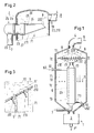
- the static degassing apparatus serves to treat a polymer-containing liquid for polymer degassing. It volatile components are separated from the polymers by the pressurized liquid is expanded in a container. At the bottom of a sump area there is a discharge pump for the degassed polymer. In upper regions of the container, a suction line for gases formed from the volatile components is connected and arranged at least one phase separation chamber. This chamber comprises an inlet for the liquid to be treated, lower openings of a polymer outlet area and a single or a plurality of upper openings of a gas outlet area.
- a highly viscous, polymer-containing liquid 7 is treated.
- This treatment is a polymer degassing in which volatile components are separated from the polymers; it is carried out by means of flash evaporation.
- the gases formed from the volatile components can be partially released from falling films and / or strands in a container 10 which is typically evacuable.
- the interior of the container 10 comprises a head portion 11, a central portion 12 and a sump portion 13 in which degassed or partially degassed polymer 73 is accumulated.
- degassed polymer 7 * is withdrawn from the container 10 at the bottom thereof by means of a discharge pump 3.
- the degassed polymer 7 * may still contain residues of volatile components, which - if necessary - can be removed in a further degassing device (not shown).
- the container 10 is connected to a suction line 4 for the released gases.
- a phase separation chamber 2 is integrated in the container 10. It is also possible for a plurality of phase separation chambers 2 to be integrated in the container 10.
- the chamber 2 comprises an inlet mouth 20 'for the liquid to be treated, a polymer outlet area with lower openings 210 and a gas outlet area with upper openings 220.
- the total cross-sectional area of the upper openings 220 compared to the entire cross-sectional area of the lower openings 210 may be substantially smaller with advantage at least 5%.
- phase separation chamber 2 takes place due to foaming a degassing.
- an average residence time in the phase separation chamber 2 of at least one, preferably two minutes to provide, this average residence time is equal to the quotient of the liquid contained in the phase separation chamber 2 and the flow rate and the chamber has a maximum filling.
- a gas-rich fraction namely a foam with bubbles or large bubbles exits through upper openings 220 (gas outlet area) from the phase separation chamber 2, the bubbles burst open, so that their content consisting of volatile components is released.
- the volatile components are removed as gas stream 8 (arrows 8) through the suction line 4 from the container 10.
- the wall of the phase separation chamber 2 is in the particular embodiment of FIG. 1 of two umbrella-shaped parts, a lower part 21 and an upper part 22, composed. Under the convex central region of the upper umbrella-shaped part 22, a stationary gas bubble can form, wherein the gas bubble can also be a foam with a very low liquid content.
- foamed plastics exhibit a structure with a self-similar, fractal-like geometry of the diameter and distribution of the bubbles ( Albalak et al. "Study of Devolatilization by SEM 9), meaning that the bubble diameters are distributed over a relatively broad range of values (the cited book describes further important findings on polymer degassing and degassing devices.)
- the gas outlet region (openings 220) and the polymer outlet region (openings 210) are arranged in edge regions of the umbrella-shaped parts 21 and 22, respectively.
- Polymer 72 (arrows 72), which emerges from the gas outlet area together with the gas stream 8, flows away downwards.
- the lower openings 210 are formed in a hole or slot shape.
- the gas-poor fraction flows divided into strand-shaped (or film-shaped) partial streams 71 from the polymer outlet region.
- the partial flows 71 move directly falling or delayed by internals (not shown) in the sump region 13 and thereby expose volatile components in the central region 12.
- the case released gas is removed via the suction line 4.
- the maximum pressure difference at the lowest openings 210 should be at most 100 mbar. At high degassing pressure, the maximum pressure difference may be higher, for example, 500 mbar.
- the pressure differences drive the two fractions through the openings 210 and 220 and on the other hand allow the bubbles to expand further, causing them to burst open.
- the partial flows 71 of the gas-lean fraction should have a throughput of at most 15 kg / h. For larger throughputs, the gas fraction of the gas-lean fraction would be undesirably high. In an industrial plant, the total throughput through the polymer exit region is generally on the order of 1 to 10 kg / s.
- the inlet 20 to the phase separation chamber 2 is disposed within the container 10 in the first embodiment. It is partially formed as a heat exchanger 6 (heat transfer medium 60 or 60 ', flow 61, caster 62). With advantage, fittings in the form of static mixer elements or heat-conducting ribs in the inlet 20, ie in a section 26 of the inlet 20, the is located in the heat exchanger 6, arranged. The internals contribute to a heat transfer from the heat transfer medium 60 in the liquid to be treated.
- the heat exchanger 6 can also deliver heat to the center space 12; a thermal insulation is not required.
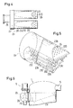
- the phase separation chamber 2 shows the head region 11 of a second degassing apparatus 1 according to the invention, in which the inlet 20 to the phase separation chamber 2 is located outside the container 10.
- the phase separation chamber 2 comprises a part 2a arranged in the container and a part 2b arranged outside.
- the inlet 20 with advantage by a heat exchanger (not shown), which may be similar to the heat exchanger 6 is formed (but with a heat-insulating jacket).
- the inner chamber part 2a is formed with two arms, as shown in Fig. 4 shows a plan view. Two arms 26 and 26 'are connected via a distributor 27 to an input-side pipe section 25.
- the walls of the arms 26, 26 'are each composed of two perforated plates 23 and 24 and a pipe part 28.
- the perforated plate 23 forms the polymer outlet region with the lower chamber openings 210, the perforated plate 24 the gas outlet region with the upper chamber openings 220.
- the gas outlet region may instead of the perforated plate 24 only consist of an opening, if the polymer to be degassed has a relatively low viscosity.
- FIG. 3 A partial cross section through the polymer outlet region is shown in detail in FIG. 3.
- the liquid 70 to be treated flows after it has been foamed. It contains bubbles 5, 5 'with different diameters.
- the larger bubbles 5 move through the buoyancy faster up than the smaller bubbles 5 ', which linger longer in the deeper areas.
- the partial streams 71 of the gas-poor fraction emerging from the chamber openings 210 contain very small bubbles 5 ", which are deformed by stretching the film-like or strand-like partial streams 71 so that they can open and release their gaseous contents into the central region 12.
- a respective guide element 211 can be arranged (see FIG. 3), by means of which the emerging partial flow 71 is directed away from the chamber wall.
- a variable hole density for example, a gradation of this density at which the density increases towards the top.
- a longer residence time of the liquid 7 to be treated in the phase separation chamber 2 can be achieved.
- a variable hole density can be provided in the gas outlet area.
- the openings 210 of the polymer outlet region and the openings 220 of the gas outlet region are each different or equal in size, wherein the openings 210 and 220 may have different shapes.
- the hole density, the hole diameter and also the thickness of the perforated plates may be adapted to a provided throughput or throughput range of the degassing apparatus 1 and / or viscosity range of the polymer.
- three lower perforated plates 23a, 23b and 23c (with the lower openings 210) form a polymer outlet region, which is wedge-shaped.
- the perforated plate 23c forms an overhanging wall piece.
- Ribs 212 direct the exiting polymer away from the orifice plates 23a, 23b and 23c.
- a metal strip 23d closes the chamber 2 against the bottom and forms their lowest points. At these lowest points preferably at least one opening (210 ') is arranged, through which the chamber 2 can run empty during a business interruption. After a resumption of operation, the degassing apparatus 1 can be restarted so easily.
- the liquid to be treated 7 can, before entering the phase separation chamber 2 by expansion means, namely by a valve, a diaphragm or a static mixer, from a relatively high pressure of For example, 3 bar to the pressure in the interior of the phase separation chamber 2 (for example, 1 bar) are relaxed.
- expansion means namely by a valve, a diaphragm or a static mixer
- FIG. 6 shows an embodiment which is a variant of the degassing apparatus 1 of FIG. 2.
- a valve 9 for a sudden relaxation of the liquid 7 with a valve body 90 is integrated in the outer part 2 b of the phase separation chamber 2.
- the relaxation devices mentioned can be integrated in the inlet 20 as in the example of FIG. 6 in the part 2b of the phase separation chamber 2 or else at another point.
- the polymer degassing of the present invention may also be carried out using a stripping agent (e.g., water, carbon dioxide, nitrogen).
- a stripping agent e.g., water, carbon dioxide, nitrogen.
- the stripping agent is added to the liquid to be treated 7 before entering the phase separation chamber 2, wherein preferably a static mixer is used.
- the stripping agent is mixed at an elevated pressure with the liquid 7 to be treated, i. So before a relaxation facilities. If the mixing is insufficient, then in the event of relaxation, damage can be caused by suddenly expanding bubbles.
Landscapes
- Chemical & Material Sciences (AREA)
- Chemical Kinetics & Catalysis (AREA)
- Engineering & Computer Science (AREA)
- Mechanical Engineering (AREA)
- Addition Polymer Or Copolymer, Post-Treatments, Or Chemical Modifications (AREA)
- Degasification And Air Bubble Elimination (AREA)
- Processes Of Treating Macromolecular Substances (AREA)
- Processing And Handling Of Plastics And Other Materials For Molding In General (AREA)
- Extraction Or Liquid Replacement (AREA)
Abstract
Description
Die Erfindung betrifft einen statischen Entgasungsapparat für eine Polymere enthaltende Flüssigkeit, zwecks Polymerentgasung, nämlich zwecks Separierung flüchtiger Komponenten von den Polymeren, sowie ein Verfahren zum Durchführen dieser Polymerentgasung. Die zu behandelnde Flüssigkeit ist beispielsweise eine Polymerlösung, in der ein Lösungsmittel die flüchtige Komponente bildet, oder eine Polymerschmelze mit Monomeren als flüchtige Komponenten.The invention relates to a static degassing apparatus for a polymer-containing liquid, for the purpose of polymer degassing, namely for the purpose of separating volatile components from the polymers, and to a process for carrying out this polymer degassing. The liquid to be treated is, for example, a polymer solution in which a solvent forms the volatile component or a polymer melt with monomers as volatile components.
Die Polymerentgasung (engl. "polymer devolatilization") ist bei der Herstellung, insbesondere Aufbereitung von Kunststoffen ein wichtiges Teilverfahren, das in vielen Fällen kritisch und daher aufwändig ist. Es steht eine Vielzahl von Entgasungsverfahren ("devolatilization processes") zur Verfügung, aus denen in Bezug auf die zu behandelnde Flüssigkeit ein geeignetes Verfahren oder eine Kombination solcher Verfahren ausgewählt werden kann. Die Wahl kann dabei empirisch aufgrund von Erfahrung und gestützt auf Versuche getroffen werden. Häufig werden maschinelle Vorrichtungen, beispielsweise Extruder oder andere mit rotierenden Bauteilen arbeitende Entgasungsvorrichtungen verwendet. Es kommen aber auch apparative Vorrichtungen, nämlich statische Entgasungsapparate zum Einsatz, bei denen nur Pumpen (Austragspumpen für entgastes Polymer, Pumpen für Wärmeträgermedien) maschinelle Komponenten bilden.Polymer devolatilization is an important sub-process in the production, in particular preparation of plastics, which in many cases is critical and therefore expensive. A variety of devolatilization processes are available from which a suitable method or combination of such methods can be selected with respect to the liquid to be treated. The choice can be made empirically based on experience and based on experiments. Often, mechanical devices such as extruders or other rotary degassing devices are used. But there are also apparatus devices, namely static degassing used in which only pumps (discharge pumps for degassed polymer, pumps for heat transfer media) machine components.
Aufgabe der Erfindung ist es, einen weiteren statischen Entgasungsapparat zu schaffen, der sich für die Entgasung einer Polymere enthaltenden Flüssigkeit eignet, wobei diese Flüssigkeit bei einer Entspannung aufschäumt und dabei ein Gemisch aus frei gesetztem Gas und gasarmem Polymer entstehen lässt. (Dabei ist ein Dampf auch als ein Gas zu verstehen und das gasarme Polymer als eine Flüssigkeit, die einen Rest an flüchtigen Komponenten einerseits in gelöster Form enthält und andererseits in Form von feinen Bläschen, deren Durchmesser über einen relativ breiten Wertebereich verteilt sind.) Die der Erfindung zugrunde liegende Aufgabe wird durch den im Anspruch 1 definierten Entgasungsapparat gelöst.The object of the invention is to provide a further static degassing apparatus, which is suitable for the degassing of a polymer-containing liquid, wherein this liquid foams at a relaxation and thereby gives rise to a mixture of free gas and gasarmem polymer. (Here, a vapor is also to be understood as a gas and the gas-poor polymer as a liquid, which has a residue of volatile Components on the one hand in dissolved form and on the other hand in the form of fine bubbles whose diameter is distributed over a relatively wide range of values.) The object underlying the invention is achieved by the degassing apparatus defined in
Der statische Entgasungsapparat dient dazu, eine Polymere enthaltende Flüssigkeit zwecks Polymerentgasung zu behandeln. Es werden dabei flüchtige Komponenten von den Polymeren separiert, indem die unter Druck stehende Flüssigkeit in einem Behälter entspannt wird. Am Boden eines Sumpfbereichs befindet sich eine Austragspumpe für das entgaste Polymer. In oberen Bereichen des Behälters ist eine Absaugleitung für aus den flüchtigen Komponenten gebildeten Gasen angeschlossen sowie mindestens eine Phasentrennkammer angeordnet. Diese Kammer umfasst einen Zulauf für die zu behandelnde Flüssigkeit, untere Öffnungen eines Polymeraustrittsbereichs und eine einzige oder eine Mehrzahl von oberen Öffnungen eines Gasaustrittsbereichs.The static degassing apparatus serves to treat a polymer-containing liquid for polymer degassing. It volatile components are separated from the polymers by the pressurized liquid is expanded in a container. At the bottom of a sump area there is a discharge pump for the degassed polymer. In upper regions of the container, a suction line for gases formed from the volatile components is connected and arranged at least one phase separation chamber. This chamber comprises an inlet for the liquid to be treated, lower openings of a polymer outlet area and a single or a plurality of upper openings of a gas outlet area.
Die abhängigen Ansprüche 2 bis 5 betreffen vorteilhafte Ausführungsformen des erfindungsgemässen Entgasungsapparats. Entsprechende Entgasungsverfahren sind Gegenstand der Ansprüche 6 bis 11.The dependent claims 2 to 5 relate to advantageous embodiments of the inventive degassing apparatus. Appropriate degassing are the subject of
Nachfolgend wird die Erfindung anhand der Zeichnungen erläutert. Es zeigen:
- Fig. 1
- eine erste Ausführungsform des erfindungsgemässen Entgasungsapparats,
- Fig. 2
- den Kopfbereich eines zweiten erfindungsgemässen Entgasungsapparats,
- Fig. 3
- ein Detail zum Entgasungsapparat der Fig. 2,
- Fig. 4
- eine Draufsicht auf eine Phasentrennkammer, die im Entgasungsapparat der Fig. 2 eingesetzt ist,
- Fig. 5
- eine weitere Phasentrennkammer und
- Fig. 6
- eine Variante zum Entgasungsapparat der Fig. 2.
- Fig. 1
- a first embodiment of the inventive degassing apparatus,
- Fig. 2
- the head region of a second degassing apparatus according to the invention,
- Fig. 3
- a detail of the degassing apparatus of Fig. 2,
- Fig. 4
- 2 is a plan view of a phase separation chamber used in the degassing apparatus of FIG. 2;
- Fig. 5
- another phase separation chamber and
- Fig. 6
- a variant of the degassing apparatus of FIG. 2.
Mit einem statischen Entgasungsapparat 1 gemäss der Erfindung, wie er als erste Ausführungsform in Fig. 1 dargestellt ist, wird beispielsweise eine hochviskose, Polymere enthaltende Flüssigkeit 7 behandelt. Diese Behandlung ist eine Polymerentgasung, bei der flüchtige Komponenten von den Polymeren separiert werden; sie wird mittels einer Entspannungsverdampfung durchgeführt. Wie bei bereits bekannten Verfahren können die aus den flüchtigen Komponenten gebildeten Gasen teilweise aus fallenden Filmen und/oder Strängen in einem Behälter 10, der in der Regel evakuierbar ist, frei gesetzt werden. Der Innenraum des Behälters 10 umfasst einen Kopfbereich 11, einen Mittenbereich 12 und einen Sumpfbereich 13, in dem entgastes oder teilweise entgastes Polymer 73 angesammelt wird. Unter Verwendung einer nicht dargestellten Einrichtung zur geregelten Niveauhaltung des Polymers 73 im Sumpfbereich 13 wird an dessen Boden mittels einer Austragspumpe 3 entgastes Polymer 7* aus dem Behälter 10 abgezogen. Das entgaste Polymer 7* kann noch Reste an flüchtigen Komponenten enthalten, die sich - falls erforderlich - in einer weiteren Entgasungseinrichtung (nicht dargestellt) entfernen lassen. Am Behälter 10 ist eine Absaugleitung 4 für die frei gesetzten Gase angeschlossen.With a
Im Kopfbereich 11 ist eine Phasentrennkammer 2 in den Behälter 10 integriert. Es können auch mehrere Phasentrennkammern 2 im Behälter 10 integriert sein. Die Kammer 2 umfasst eine Zulaufsmündung 20' für die zu behandelnde Flüssigkeit, einen Polymeraustrittsbereich mit unteren Öffnungen 210 und einen Gasaustrittsbereich mit oberen Öffnungen 220. Die gesamte Querschnittsfläche der oberen Öffnungen 220 verglichen mit der gesamten Querschnittsfläche der unteren Öffnungen 210 kann wesentlich kleiner sein und beträgt mit Vorteil mindestens 5%.In the
In der Phasentrennkammer 2 erfolgt aufgrund einer Schaumbildung eine Entgasung. Zur Entwicklung des Schaums ist eine mittlere Verweilzeit in der Phasentrennkammer 2 von mindestens einer, vorzugsweise zwei Minuten vorzusehen, wobei diese mittlere Verweilzeit gleich dem Quotienten aus der in der Phasentrennkammer 2 enthaltenden Flüssigkeitsmenge und dem Durchsatz ist und die Kammer eine maximale Füllung aufweist. Eine gasreiche Fraktion, nämlich ein Schaum mit Blasen oder grossen Bläschen tritt durch obere Öffnungen 220 (Gasaustrittsbereich) aus der Phasentrennkammer 2 aus, wobei die Bläschen aufplatzen, so dass deren aus flüchtigen Komponenten bestehender Inhalt frei gesetzt wird. Je grösser der Abstand zwischen der Zulaufsmündung 20' und dem Gasaustrittsbereich ist und je grösser die mittlere Verweilzeit ist, desto länger ist die Dauer, während welcher der Gasanteil der gasreichen Fraktion zunehmen kann. Die flüchtigen Komponenten werden als Gasstrom 8 (Pfeile 8) durch die Absaugleitung 4 aus dem Behälter 10 entfernt. Die Wandung der Phasentrennkammer 2 ist bei der besonderen Ausführungsform der Fig. 1 aus zwei schirmförmigen Teilen, einem unteren Teil 21 und einem oberen Teil 22, zusammengesetzt. Unter dem konvexen Zentralbereich des oberen schirmförmigen Teils 22 kann sich eine stationäre Gasblase ausbilden, wobei die Gasblase auch ein Schaum mit sehr geringem Flüssigkeitsanteil sein kann.In the
Eine gasarme Fraktion, die einen Rest an flüchtigen Komponenten in gelöster Form und in Form von feinen Bläschen enthält, tritt durch untere Öffnungen 210 aus der Phasentrennkammer 2 aus. Wie aus dem Buch "
Der Gasaustrittsbereich (Öffnungen 220) und der Polymeraustrittsbereich (Öffnungen 210) sind in Randbereichen der schirmförmigen Teile 21 bzw. 22 angeordnet. Polymer 72 (Pfeile 72), das zusammen mit dem Gasstrom 8 aus dem Gasaustrittsbereich austritt, fliesst nach unten weg.The gas outlet region (openings 220) and the polymer outlet region (openings 210) are arranged in edge regions of the umbrella-
Für eine weitere Entgasung sind die unteren Öffnungen 210 loch- oder schlitzförmig ausgebildet. Die gasarme Fraktion fliesst aufgeteilt auf strangförmige (bzw. filmförmige) Teilströme 71 aus dem Polymeraustrittsbereich aus. Die Teilströme 71 bewegen sich direkt fallend oder durch Einbauten verzögert (nicht dargestellt) in den Sumpfbereich 13 und setzen dabei flüchtige Komponenten in den Mittenbereich 12 frei. Das dabei frei gesetzte Gas wird über die Absaugleitung 4 abgeführt.For a further degassing, the
Es bestehen Druckunterschiede zwischen dem Innenraum der Phasentrennkammer 2 und dem Mittenbereich 12 des Behälters 10. Wird die Entgasung bei einem tiefen Druck betrieben (erzeugt durch Vakuumpumpe), so soll der maximale Druckunterschied bei den tiefst liegenden Öffnungen 210 höchstens 100 mbar betragen. Bei hohem Entgasungsdruck kann der maximale Druckunterschied auch höher, beispielsweise 500 mbar betragen. Die Druckunterschiede treiben einerseits die beiden Fraktionen durch die Öffnungen 210 bzw. 220 und lassen andererseits die Blasen weiter expandieren, so dass diese aufplatzen. Die Teilströme 71 der gasarmen Fraktion sollen einen Durchsatz von höchstens 15 kg/h aufweisen. Bei grösseren Durchsätzen wäre der Gasanteil der gasarmen Fraktion unerwünscht hoch. In einer industriellen Anlage hat der gesamte Durchsatz durch den Polymeraustrittsbereich in der Regel einen Wert in der Grössenordnung von 1 bis 10 kg/s.There are pressure differences between the interior of the
Der Zulauf 20 zur Phasentrennkammer 2 ist bei der ersten Ausführungsform innerhalb des Behälters 10 angeordnet. Er ist teilweise als Wärmetauscher 6 ausgebildet (Wärmeträgermedium 60 bzw. 60', Vorlauf 61, Nachlauf 62). Mit Vorteil sind Einbauten in Form von statischen Mischerelementen oder Wärmeleitrippen im Zulauf 20, d.h. in einem Abschnitt 26 des Zulaufs 20, der sich im Wärmetauscher 6 befindet, angeordnet. Die Einbauten tragen zu einem Wärmetransport aus dem Wärmeträgermedium 60 in die zu behandelnde Flüssigkeit bei. Der Wärmetauscher 6 kann auch Wärme an den Mittenraum 12 abgeben; eine Wärmedämmung ist somit nicht erforderlich.The
Fig. 2 zeigt den Kopfbereich 11 eines zweiten erfindungsgemässen Entgasungsapparats 1, bei dem sich der Zulauf 20 zur Phasentrennkammer 2 ausserhalb des Behälters 10 befindet. Die Phasentrennkammer 2 umfasst einen im Behälter angeordneten Teil 2a und einen ausserhalb angeordneten Teil 2b. Auch hier führt der Zulauf 20 mit Vorteil durch einen Wärmetauscher (nicht dargestellt), der ähnlich wie der Wärmetauscher 6 ausgebildet sein kann (jedoch mit einem wärmedämmenden Mantel). Der innere Kammerteil 2a ist zweiarmig ausgebildet, wie eine in Fig. 4 dargestellte Draufsicht zeigt. Zwei Arme 26 und 26' sind über ein Verteilstück 27 an ein eingangsseitiges Rohrstück 25 angeschlossen. Die Wandungen der Arme 26, 26' sind jeweils aus zwei Lochplatten 23 sowie 24 und einem Rohrteil 28 zusammengesetzt. Die Lochplatte 23 bildet den Polymeraustrittsbereich mit den unteren Kammeröffnungen 210, die Lochplatte 24 den Gasaustrittsbereich mit den oberen Kammeröffnungen 220. Der Gasaustrittsbereich kann anstelle der Lochplatte 24 auch nur aus einer Öffnung bestehen, falls das zu entgasende Polymer eine relativ kleine Viskosität hat.2 shows the
Einen teilweisen Querschnitt durch den Polymeraustrittsbereich zeigt die Detaildarstellung in Fig. 3. Über der Lochplatte 23 fliesst die zu behandelnde Flüssigkeit 70 nach deren Schaumbildung. Sie enthält Bläschen 5, 5' mit verschieden grossen Durchmessern. Die grösseren Bläschen 5 bewegen sich durch den Auftrieb rascher nach oben als die kleineren Bläschen 5', die in den tieferen Bereichen länger verweilen. Die aus den Kammeröffnungen 210 austretenden Teilströme 71 der gasarmen Fraktion enthalten sehr kleine Bläschen 5", die durch ein Strecken der film- oder strangförmigen Teilströme 71 so deformiert werden, dass sie sich öffnen und ihren gasförmigen Inhalt in den Mittenbereich 12 abgeben können.A partial cross section through the polymer outlet region is shown in detail in FIG. 3. Above the
Am Ausgang der unteren Kammeröffnungen 210 kann jeweils ein Leitelement 211 angeordnet sein (siehe Fig. 3), mittels dem der austretende Teilstrom 71 von der Kammerwandung weg gelenkt wird.At the outlet of the
Es kann von Vorteil sein, die Löcher 210 des Polymeraustrittsbereichs ungleichmässig zu verteilen, so dass eine variable Löcherdichte vorliegt, beispielsweise eine Abstufung dieser Dichte, bei der die Dichte gegen oben zunimmt. Dadurch lässt sich eine längere Verweilzeit der zu behandelnden Flüssigkeit 7 in der Phasentrennkammer 2 erreichen. Auch im Gasaustrittsbereich kann eine variable Löcherdichte vorgesehen sein. Die Öffnungen 210 des Polymeraustrittsbereichs sowie die Öffnungen 220 des Gasaustrittsbereichs sind jeweils verschieden oder gleich gross, wobei die Öffnungen 210 bzw. 220 verschiedene Formen aufweisen können. Die Löcherdichte, die Löcherdurchmesser und auch die Dicke der Lochplatten kann auf einen vorgesehenen Durchsatz oder Durchsatzbereich des Entgasungsapparats 1 und/oder Viskositätsbereich des Polymers angepasst sein.It may be advantageous to distribute the
Bei der in Fig. 5 gezeigten Variante der Phasentrennkammer 2 bilden drei untere Lochbleche 23a, 23b und 23c (mit den unteren Öffnungen 210) einen Polymeraustrittsbereich, der keilförmig ausgebildet ist. Das Lochblech 23c bildet ein überhängendes Wandstück. Rippen 212 lenken das austretende Polymer von den Lochplatten 23a, 23b und 23c weg. Ein Blechstreifen 23d schliesst die Kammer 2 gegen unten ab und bildet deren tiefst liegenden Stellen. An diesen tiefsten Stellen ist vorzugsweise mindestens eine Öffnung (210') angeordnet, durch welche die Kammer 2 bei einem Betriebsunterbruch leer laufen kann. Nach einer Wiederaufnahme des Betriebs lässt sich der Entgasungsapparat 1 so problemlos wieder anfahren.In the variant of the
Die zu behandelnde Flüssigkeit 7 kann vor Eintritt in die Phasentrennkammer 2 durch Entspannungseinrichtungen, nämlich durch ein Ventil, eine Blende oder einen statischen Mischer, von einem relativ hohen Druck von beispielsweise 3 bar auf den Druck im Innenraum der Phasentrennkammer 2 (beispielsweise 1 bar) entspannt werden.The liquid to be treated 7 can, before entering the
Fig. 6 zeigt eine Ausführungsform, die eine Variante zum Entgasungsapparat 1 der Fig. 2 ist. Ein Ventil 9 zu einer sprungartigen Entspannung der Flüssigkeit 7 mit einem Ventilkörper 90 ist in den äusseren Teil 2b der Phasentrennkammer 2 integriert. Die genannten Entspannungseinrichtungen können wie im Beispiel der Fig. 6 im Teil 2b der Phasentrennkammer 2 oder auch an einer sonstigen Stelle im Zulauf 20 integriert sein.FIG. 6 shows an embodiment which is a variant of the
Die erfindungsgemässe Polymerentgasung kann auch unter Verwendung eines Strippmittels (z.B. Wasser, Kohlendioxid, Stickstoff) durchgeführt werden. Das Strippmittel wird der zu behandelnden Flüssigkeit 7 vor Eintritt in die Phasentrennkammer 2 beigemischt, wobei dazu vorzugsweise ein statischer Mischer eingesetzt wird. Mit Vorteil wird das Strippmittel bei einem erhöhten Druck mit der zu behandelnden Flüssigkeit 7 vermischt, d.h. also vor einer Entspannungseinrichtungen. Ist die Vermischung ungenügend, so können bei einer Entspannung Schäden durch schlagartig expandierende Blasen entstehen.The polymer degassing of the present invention may also be carried out using a stripping agent (e.g., water, carbon dioxide, nitrogen). The stripping agent is added to the liquid to be treated 7 before entering the
Claims (11)
Priority Applications (1)
| Application Number | Priority Date | Filing Date | Title |
|---|---|---|---|
| EP06124662.5A EP1800724B1 (en) | 2005-12-21 | 2006-11-23 | Process for static degassing a liquid containing polymers |
Applications Claiming Priority (2)
| Application Number | Priority Date | Filing Date | Title |
|---|---|---|---|
| EP05405711 | 2005-12-21 | ||
| EP06124662.5A EP1800724B1 (en) | 2005-12-21 | 2006-11-23 | Process for static degassing a liquid containing polymers |
Publications (2)
| Publication Number | Publication Date |
|---|---|
| EP1800724A1 true EP1800724A1 (en) | 2007-06-27 |
| EP1800724B1 EP1800724B1 (en) | 2019-06-19 |
Family
ID=36499138
Family Applications (1)
| Application Number | Title | Priority Date | Filing Date |
|---|---|---|---|
| EP06124662.5A Active EP1800724B1 (en) | 2005-12-21 | 2006-11-23 | Process for static degassing a liquid containing polymers |
Country Status (11)
| Country | Link |
|---|---|
| US (1) | US7942955B2 (en) |
| EP (1) | EP1800724B1 (en) |
| JP (1) | JP5201828B2 (en) |
| KR (1) | KR101288432B1 (en) |
| CN (1) | CN1986619B (en) |
| BR (1) | BRPI0605329A (en) |
| CA (1) | CA2568826C (en) |
| ES (1) | ES2743610T3 (en) |
| MX (1) | MXPA06015200A (en) |
| RU (1) | RU2414948C2 (en) |
| TW (1) | TWI381874B (en) |
Cited By (6)
| Publication number | Priority date | Publication date | Assignee | Title |
|---|---|---|---|---|
| EP2353839A1 (en) * | 2010-01-27 | 2011-08-10 | Coperion GmbH | Method and plant for degasing polymer melts |
| EP2881154A1 (en) | 2013-12-04 | 2015-06-10 | Fluitec Invest AG | Method and device for flash evaporation |
| EP2987814A1 (en) | 2014-08-19 | 2016-02-24 | PURAC Biochem BV | Lactide block copolymer and method of preparation |
| CN107538706A (en) * | 2017-10-12 | 2018-01-05 | 威海新元化工有限公司 | A kind of system and method that volatile matter in fluorine-silicon compounded rubber stock is removed using inert gas |
| WO2020002358A1 (en) | 2018-06-26 | 2020-01-02 | Total Corbion Pla Bv | Process for the preparation of lactide and polylactide mixture |
| WO2020245063A1 (en) | 2019-06-03 | 2020-12-10 | Total Corbion Pla Bv | Process for preparing stabilized aliphatic polyester, and compositions obtained therewith |
Families Citing this family (21)
| Publication number | Priority date | Publication date | Assignee | Title |
|---|---|---|---|---|
| ES2743610T3 (en) * | 2005-12-21 | 2020-02-20 | Sulzer Management Ag | Static degassing procedure of a liquid containing polymers |
| UA103898C2 (en) * | 2008-07-31 | 2013-12-10 | ПУРАК Биокем БВ | Continuous process of polyester production |
| DE102011054180A1 (en) * | 2011-10-05 | 2013-04-11 | List Holding Ag | Process for the thermal separation of a volatile substance from a non-volatile or less volatile substrate |
| EP2772290A1 (en) * | 2013-02-28 | 2014-09-03 | Sulzer Chemtech AG | A devolatilisation apparatus and a process for use thereof |
| JP6416134B2 (en) | 2013-03-15 | 2018-10-31 | スルザー ケムテック アクチェンゲゼルシャフト | Method for preparing a polyester polymer composition comprising a polyester polymer having furan units, and the polyester polymer composition obtained thereby and use thereof |
| US11071934B2 (en) | 2013-06-24 | 2021-07-27 | Parker-Hannifin Corporation | Filter elements, coalescing baffles, filtration vessel and methods |
| US9815012B2 (en) | 2013-06-24 | 2017-11-14 | Pecofacet (Us), Inc. | Filter elements, coalescing baffles, filtration vessel and methods |
| EP2998337A1 (en) | 2014-09-17 | 2016-03-23 | Sulzer Chemtech AG | A method for stabilizing a condensed phase composition including a cyclic ester for example in a process of manufacturing a polyester |
| BR112017005394B1 (en) | 2014-09-17 | 2021-07-06 | Sulzer Management Ag | METHOD FOR STABILIZING A CONDENSED PHASE COMPOSITION, CONDENSED PHASE COMPOSITION, AND USES OF A CONDENSED PHASE COMPOSITION |
| CN104815448A (en) * | 2015-03-03 | 2015-08-05 | 湖北东方化工有限公司 | Flash evaporator for gasifying liquid phase substances |
| KR101713215B1 (en) | 2015-08-11 | 2017-03-07 | 롯데케미칼 주식회사 | Preparation method of polylactic acid |
| US9840571B2 (en) | 2016-02-04 | 2017-12-12 | Chevron Phillips Chemical Company Lp | Inert stripping of volatile organic compounds from polymer melts |
| US10384399B2 (en) | 2016-03-08 | 2019-08-20 | The Boeing Company | Systems and methods for depositing compounds in a structure |
| US10512857B2 (en) * | 2016-03-08 | 2019-12-24 | The Boeing Company | Systems and methods for viscous material vacuum deaeration, and systems and methods for depositing compounds in a structure |
| US20180264731A1 (en) * | 2017-03-15 | 2018-09-20 | Xjet Ltd. | System and method for delivering ink into a 3d printing apparatus |
| RU2660120C1 (en) * | 2017-05-29 | 2018-07-05 | Юрий Павлович Скакунов | Device for cleaning liquid from gas impurities (de-aerator, degasifier evaporator) |
| KR102635673B1 (en) | 2019-09-30 | 2024-02-14 | 주식회사 엘지화학 | Devolatilization system, method of devolatilization and preparing method of styrene-nitrile based copolymer using the same |
| KR102601077B1 (en) | 2019-09-30 | 2023-11-10 | 주식회사 엘지화학 | Devolatilization system, method of devolatilization and preparing method of styrene-nitrile based copolymer using the same |
| CN111637726A (en) * | 2020-05-06 | 2020-09-08 | 安徽省金宜食品有限公司 | Natural products draws drying device |
| CN113813640A (en) * | 2021-10-14 | 2021-12-21 | 丽江英煌集生物工程有限公司 | Purified macamide activity refining device and method |
| CN115300933B (en) * | 2022-07-28 | 2023-11-24 | 黄淮学院 | Separation and purification equipment for natural products |
Citations (8)
| Publication number | Priority date | Publication date | Assignee | Title |
|---|---|---|---|---|
| US2564584A (en) * | 1948-10-05 | 1951-08-14 | Worthington Pump & Mach Corp | Deaerating feed-water heater |
| DE2331314A1 (en) * | 1973-06-20 | 1975-01-16 | Voith Gmbh J M | Vacuum degassing of paper slurries - by spraying into vessel connected to vacuum source |
| CA1251403A (en) * | 1987-11-26 | 1989-03-21 | Ross Smith | Well effluent separator |
| EP0369708A1 (en) * | 1988-11-15 | 1990-05-23 | Novacor Chemicals (International) S.A. | Devolatilization |
| WO1997049473A1 (en) * | 1996-06-27 | 1997-12-31 | Holcomb Robert R | Water treatment device and method |
| US6224716B1 (en) * | 1998-03-18 | 2001-05-01 | Oilquip, Inc. | Apparatus for dehydrating oil |
| US6436242B1 (en) * | 2000-02-10 | 2002-08-20 | Pedro Joaquin Sanchez Belmar | Device and method for distilling water |
| WO2004018522A2 (en) * | 2002-08-23 | 2004-03-04 | Fina Technology, Inc. | Apparatus and method for removal of volatiles from a mass processable polymer |
Family Cites Families (44)
| Publication number | Priority date | Publication date | Assignee | Title |
|---|---|---|---|---|
| US1518784A (en) * | 1921-04-13 | 1924-12-09 | Cochrane Corp | Method and apparatus for purifying water |
| US1416632A (en) * | 1921-12-27 | 1922-05-16 | Fothergill Harry | Apparatus for removing gases from liquids |
| US1511876A (en) * | 1922-02-08 | 1924-10-14 | Elliott Co | Degasifying apparatus |
| US2282622A (en) * | 1939-05-01 | 1942-05-12 | Gladys J Torrence | Method for treating juices |
| US2235593A (en) * | 1940-02-26 | 1941-03-18 | Henry J Schneider | Dynamic deaerator and water heater |
| US2313175A (en) * | 1941-03-20 | 1943-03-09 | Carbide & Carbon Chem Corp | Vacuum distillation process and apparatus |
| US2308721A (en) * | 1941-05-20 | 1943-01-19 | Worthington Pump & Mach Corp | Feed-water heater |
| US2452716A (en) * | 1945-08-04 | 1948-11-02 | Elliott Co | Deaerating heater |
| US2564583A (en) * | 1948-09-30 | 1951-08-14 | Worthington Pump & Mach Corp | Deaerating feed-water heater |
| US2738852A (en) * | 1954-02-09 | 1956-03-20 | Elliott Co | Deaerating heater |
| US2887955A (en) * | 1954-06-29 | 1959-05-26 | Texas Instruments Inc | Seismic mud pump |
| US2979156A (en) * | 1959-05-01 | 1961-04-11 | Worthington Corp | Vacuum degasifier |
| US3257173A (en) * | 1960-08-23 | 1966-06-21 | Du Pont | Polymer finishing apparatus |
| US3113871A (en) * | 1960-12-23 | 1963-12-10 | Air Reduction | Preparation of fruit juices |
| US3213594A (en) * | 1962-10-16 | 1965-10-26 | Bass Brothers Entpr Inc | Mud treating device |
| US3325974A (en) * | 1963-09-11 | 1967-06-20 | Bass Brothers Entpr Inc | Drilling mud degassers for oil wells |
| SE331946B (en) * | 1966-12-15 | 1971-01-18 | N Wikdahl | |
| US3793805A (en) * | 1971-12-13 | 1974-02-26 | Eastman Kodak Co | Method and apparatus for removing air from a liquid |
| US3834133A (en) * | 1972-12-22 | 1974-09-10 | Foster Wheeler Corp | Direct contact condenser having an air removal system |
| US3853672A (en) * | 1973-01-09 | 1974-12-10 | Monsanto Co | Falling strand devolatilizer using one preheater with two flash chambers |
| US3966538A (en) | 1973-01-09 | 1976-06-29 | Monsanto Company | Falling strand devolatilization apparatus |
| US3853513A (en) * | 1973-07-02 | 1974-12-10 | Universal Oil Prod Co | Vapor-liquid separation apparatus |
| US3926594A (en) * | 1975-01-06 | 1975-12-16 | Us Navy | Water trap for pitot static system |
| JPS5317569A (en) * | 1976-08-02 | 1978-02-17 | Mitsubishi Chem Ind Ltd | Apparatus for treating material of high viscosity |
| FR2472134B2 (en) * | 1979-05-04 | 1986-07-11 | Pernin Const Meca | GAS SEPARATOR FOR LIQUID DISPENSING DEVICE |
| US4385908A (en) * | 1981-11-06 | 1983-05-31 | Air Conditioning Corporation | High pressure condensate return apparatus and method and system for using the same |
| US4392874A (en) * | 1981-11-25 | 1983-07-12 | The United States Of America As Represented By The Administrator Of The National Aeronautics And Space Administration | Degassifying and mixing apparatus for liquids |
| FR2573320B1 (en) * | 1984-11-20 | 1989-06-30 | Delas Weir Sa | DEVICE FOR DEGASSING A LIQUID FLUID |
| JPS61203103A (en) * | 1985-03-05 | 1986-09-09 | Mitsui Eng & Shipbuild Co Ltd | Heat exchanger in apparatus for removing volatile matter from polymer |
| NL8502592A (en) * | 1985-09-20 | 1987-04-16 | Stork Ketels Mij Tot Expl Van | SPRAY UNIT AND DEGASING PLANT. |
| CA1265289A (en) | 1985-12-16 | 1990-01-30 | Viney Pal Aneja | Method and apparatus for devolatilizing polymer solutions |
| FI872967A (en) * | 1987-07-06 | 1989-01-07 | Ahlstroem Oy | PUMP OCH FOERFARANDE FOER SEPARERING AV GAS MED PUMPEN UR MEDIET SOM SKALL PUMPAS. |
| IT1226303B (en) * | 1988-07-26 | 1990-12-27 | Montedipe Spa | PROCESS AND APPARATUS FOR DEVOLATILIZATION OF POLYMER SOLUTIONS. |
| JP2762600B2 (en) * | 1988-08-29 | 1998-06-04 | 大日本インキ化学工業株式会社 | Device for devolatilizing polymer solution and method for devolatilizing polymer solution using the same |
| CA2128968C (en) * | 1993-07-30 | 2000-05-02 | Junsuke Yabumoto | Bubble separating apparatus |
| ES2105473T3 (en) * | 1993-11-25 | 1997-10-16 | Basf Ag | PROCEDURE FOR THE ELIMINATION OF RESIDUAL VOLATILE PARTS OF POLYACRYLATE CAST MASSES. |
| US6932889B1 (en) * | 1996-06-27 | 2005-08-23 | Robert R. Holcomb | Water treatment device and method |
| DE19919521A1 (en) * | 1999-04-29 | 2000-11-02 | Micafil Ag Zuerich | Device for mixing and degassing a flowable mass |
| JP4414519B2 (en) * | 1999-09-16 | 2010-02-10 | 帝人株式会社 | Resin manufacturing equipment and manufacturing method |
| JP2001232183A (en) | 2000-02-23 | 2001-08-28 | Sumitomo Heavy Ind Ltd | Liquid dispersion supplying unit and vacuum liquid treating device |
| DE10016894A1 (en) * | 2000-04-05 | 2001-10-18 | Bayer Ag | Method and device for removing volatile constituents from polymer compositions |
| JP2003130499A (en) * | 2001-10-30 | 2003-05-08 | Tgk Co Ltd | Expansion valve |
| US7407019B2 (en) * | 2005-03-16 | 2008-08-05 | Weatherford Canada Partnership | Method of dynamically controlling open hole pressure in a wellbore using wellhead pressure control |
| ES2743610T3 (en) * | 2005-12-21 | 2020-02-20 | Sulzer Management Ag | Static degassing procedure of a liquid containing polymers |
-
2006
- 2006-11-23 ES ES06124662T patent/ES2743610T3/en active Active
- 2006-11-23 EP EP06124662.5A patent/EP1800724B1/en active Active
- 2006-11-24 CA CA2568826A patent/CA2568826C/en not_active Expired - Fee Related
- 2006-11-30 TW TW095144456A patent/TWI381874B/en active
- 2006-12-11 KR KR1020060125590A patent/KR101288432B1/en active IP Right Grant
- 2006-12-19 US US11/641,291 patent/US7942955B2/en active Active
- 2006-12-20 CN CN200610169089XA patent/CN1986619B/en active Active
- 2006-12-20 BR BRPI0605329-7A patent/BRPI0605329A/en not_active Application Discontinuation
- 2006-12-20 JP JP2006342013A patent/JP5201828B2/en active Active
- 2006-12-20 MX MXPA06015200A patent/MXPA06015200A/en active IP Right Grant
- 2006-12-20 RU RU2006145592/05A patent/RU2414948C2/en active
Patent Citations (8)
| Publication number | Priority date | Publication date | Assignee | Title |
|---|---|---|---|---|
| US2564584A (en) * | 1948-10-05 | 1951-08-14 | Worthington Pump & Mach Corp | Deaerating feed-water heater |
| DE2331314A1 (en) * | 1973-06-20 | 1975-01-16 | Voith Gmbh J M | Vacuum degassing of paper slurries - by spraying into vessel connected to vacuum source |
| CA1251403A (en) * | 1987-11-26 | 1989-03-21 | Ross Smith | Well effluent separator |
| EP0369708A1 (en) * | 1988-11-15 | 1990-05-23 | Novacor Chemicals (International) S.A. | Devolatilization |
| WO1997049473A1 (en) * | 1996-06-27 | 1997-12-31 | Holcomb Robert R | Water treatment device and method |
| US6224716B1 (en) * | 1998-03-18 | 2001-05-01 | Oilquip, Inc. | Apparatus for dehydrating oil |
| US6436242B1 (en) * | 2000-02-10 | 2002-08-20 | Pedro Joaquin Sanchez Belmar | Device and method for distilling water |
| WO2004018522A2 (en) * | 2002-08-23 | 2004-03-04 | Fina Technology, Inc. | Apparatus and method for removal of volatiles from a mass processable polymer |
Cited By (7)
| Publication number | Priority date | Publication date | Assignee | Title |
|---|---|---|---|---|
| EP2353839A1 (en) * | 2010-01-27 | 2011-08-10 | Coperion GmbH | Method and plant for degasing polymer melts |
| EP2881154A1 (en) | 2013-12-04 | 2015-06-10 | Fluitec Invest AG | Method and device for flash evaporation |
| EP2987814A1 (en) | 2014-08-19 | 2016-02-24 | PURAC Biochem BV | Lactide block copolymer and method of preparation |
| WO2016026859A1 (en) | 2014-08-19 | 2016-02-25 | Purac Biochem Bv | Lactide block copolymer and method of preparation |
| CN107538706A (en) * | 2017-10-12 | 2018-01-05 | 威海新元化工有限公司 | A kind of system and method that volatile matter in fluorine-silicon compounded rubber stock is removed using inert gas |
| WO2020002358A1 (en) | 2018-06-26 | 2020-01-02 | Total Corbion Pla Bv | Process for the preparation of lactide and polylactide mixture |
| WO2020245063A1 (en) | 2019-06-03 | 2020-12-10 | Total Corbion Pla Bv | Process for preparing stabilized aliphatic polyester, and compositions obtained therewith |
Also Published As
| Publication number | Publication date |
|---|---|
| RU2414948C2 (en) | 2011-03-27 |
| TWI381874B (en) | 2013-01-11 |
| EP1800724B1 (en) | 2019-06-19 |
| CN1986619B (en) | 2012-09-05 |
| MXPA06015200A (en) | 2008-10-24 |
| US20070137488A1 (en) | 2007-06-21 |
| CN1986619A (en) | 2007-06-27 |
| RU2006145592A (en) | 2008-06-27 |
| CA2568826A1 (en) | 2007-06-21 |
| JP2007186694A (en) | 2007-07-26 |
| KR20070067617A (en) | 2007-06-28 |
| US7942955B2 (en) | 2011-05-17 |
| JP5201828B2 (en) | 2013-06-05 |
| BRPI0605329A (en) | 2007-10-09 |
| CA2568826C (en) | 2014-01-07 |
| ES2743610T3 (en) | 2020-02-20 |
| KR101288432B1 (en) | 2013-07-26 |
| TW200735946A (en) | 2007-10-01 |
Similar Documents
| Publication | Publication Date | Title |
|---|---|---|
| EP1800724B1 (en) | Process for static degassing a liquid containing polymers | |
| DE19822437C1 (en) | Method and apparatus for physical clarification of a liquid such as, for example, a glass melt | |
| DE2842868C2 (en) | ||
| DE3019888A1 (en) | METHOD AND DEVICE FOR PRODUCING MOLDED BODIES FROM LIQUID OR PASTOSE MIXTURES | |
| DE69813711T2 (en) | Process for removing volatiles from a polymer composition | |
| EP0462317B1 (en) | Apparatus and method for the precipitation of polymers | |
| DE2400661A1 (en) | IMPROVED FALL FLOW EVAPORATION PROCESS | |
| DE3336179A1 (en) | DEVICE FOR PRODUCING FOAMED THERMOPLASTIC PLASTICS, LIKE POLYSTYRENE, POLYAETHYLENE OR THE LIKE | |
| DE19521713C1 (en) | Extruder removing volatile matter from thermoplastic by water injection | |
| EP2140920A2 (en) | Twisting element, inlet valve, device and method of removing gas from fluids | |
| DE2129336A1 (en) | Method for carrying out a gas-liquid contact reaction and there for suitable device | |
| DE10126124A1 (en) | Extruder for production of continuous plastic sheet has gas sealing blocks around the nozzle outlet and take-off rolls | |
| DE60306949T2 (en) | METHOD AND DEVICE FOR DEGASSING A POLYMER | |
| EP1242156A1 (en) | Strand evaporator | |
| EP3374317B1 (en) | Method for degassing water, and degassing device | |
| DE3433830C2 (en) | Method and rotation processing device for processing viscous and viscous-elastic liquid materials | |
| EP3651968B1 (en) | Extruder system with pressure regulating device | |
| EP0673963A1 (en) | Process for continuously producing expanded polymer beads | |
| EP2881154B1 (en) | Method and device for flash evaporation | |
| DE102010060320A1 (en) | Process for the thermal separation of a solution of thermoplastic polymer and solvent | |
| WO2007020296A1 (en) | Cavitation degasifier | |
| DE3628994A1 (en) | CONTINUOUS METHOD FOR REMOVING SOLVED MATERIALS FROM POLYMER SOLUTIONS | |
| EP1009509B1 (en) | Method for reducing the formation of foam during the treatment of a dispersion or a liquid with water vapour | |
| DD223641A1 (en) | METHOD AND DEVICE FOR CONTINUOUS DISCHARGING OF VISCOUS FLUIDS | |
| DE1901163A1 (en) | Method and device for mixing, removing volatile substances and extrusion |
Legal Events
| Date | Code | Title | Description |
|---|---|---|---|
| PUAI | Public reference made under article 153(3) epc to a published international application that has entered the european phase |
Free format text: ORIGINAL CODE: 0009012 |
|
| AK | Designated contracting states |
Kind code of ref document: A1 Designated state(s): AT BE BG CH CY CZ DE DK EE ES FI FR GB GR HU IE IS IT LI LT LU LV MC NL PL PT RO SE SI SK TR |
|
| AX | Request for extension of the european patent |
Extension state: AL BA HR MK YU |
|
| 17P | Request for examination filed |
Effective date: 20071130 |
|
| AKX | Designation fees paid |
Designated state(s): AT BE BG CH CY CZ DE DK EE ES FI FR GB GR HU IE IS IT LI LT LU LV MC NL PL PT RO SE SI SK TR |
|
| 17Q | First examination report despatched |
Effective date: 20080228 |
|
| STAA | Information on the status of an ep patent application or granted ep patent |
Free format text: STATUS: EXAMINATION IS IN PROGRESS |
|
| GRAP | Despatch of communication of intention to grant a patent |
Free format text: ORIGINAL CODE: EPIDOSNIGR1 |
|
| STAA | Information on the status of an ep patent application or granted ep patent |
Free format text: STATUS: GRANT OF PATENT IS INTENDED |
|
| INTG | Intention to grant announced |
Effective date: 20180914 |
|
| RAP1 | Party data changed (applicant data changed or rights of an application transferred) |
Owner name: SULZER CHEMTECH AG |
|
| GRAJ | Information related to disapproval of communication of intention to grant by the applicant or resumption of examination proceedings by the epo deleted |
Free format text: ORIGINAL CODE: EPIDOSDIGR1 |
|
| STAA | Information on the status of an ep patent application or granted ep patent |
Free format text: STATUS: EXAMINATION IS IN PROGRESS |
|
| INTC | Intention to grant announced (deleted) | ||
| GRAP | Despatch of communication of intention to grant a patent |
Free format text: ORIGINAL CODE: EPIDOSNIGR1 |
|
| STAA | Information on the status of an ep patent application or granted ep patent |
Free format text: STATUS: GRANT OF PATENT IS INTENDED |
|
| INTG | Intention to grant announced |
Effective date: 20190314 |
|
| GRAS | Grant fee paid |
Free format text: ORIGINAL CODE: EPIDOSNIGR3 |
|
| GRAA | (expected) grant |
Free format text: ORIGINAL CODE: 0009210 |
|
| STAA | Information on the status of an ep patent application or granted ep patent |
Free format text: STATUS: THE PATENT HAS BEEN GRANTED |
|
| REG | Reference to a national code |
Ref country code: DE Ref legal event code: R081 Ref document number: 502006016273 Country of ref document: DE Owner name: SULZER MANAGEMENT AG, CH Free format text: FORMER OWNER: SULZER CHEMTECH AG, WINTERTHUR, CH |
|
| AK | Designated contracting states |
Kind code of ref document: B1 Designated state(s): AT BE BG CH CY CZ DE DK EE ES FI FR GB GR HU IE IS IT LI LT LU LV MC NL PL PT RO SE SI SK TR |
|
| REG | Reference to a national code |
Ref country code: GB Ref legal event code: FG4D Free format text: NOT ENGLISH |
|
| REG | Reference to a national code |
Ref country code: CH Ref legal event code: EP |
|
| REG | Reference to a national code |
Ref country code: IE Ref legal event code: FG4D Free format text: LANGUAGE OF EP DOCUMENT: GERMAN |
|
| REG | Reference to a national code |
Ref country code: DE Ref legal event code: R096 Ref document number: 502006016273 Country of ref document: DE |
|
| REG | Reference to a national code |
Ref country code: AT Ref legal event code: REF Ref document number: 1144757 Country of ref document: AT Kind code of ref document: T Effective date: 20190715 |
|
| REG | Reference to a national code |
Ref country code: NL Ref legal event code: FP |
|
| REG | Reference to a national code |
Ref country code: CH Ref legal event code: NV Representative=s name: NOVAGRAAF INTERNATIONAL SA, CH |
|
| RAP2 | Party data changed (patent owner data changed or rights of a patent transferred) |
Owner name: SULZER MANAGEMENT AG |
|
| PG25 | Lapsed in a contracting state [announced via postgrant information from national office to epo] |
Ref country code: SE Free format text: LAPSE BECAUSE OF FAILURE TO SUBMIT A TRANSLATION OF THE DESCRIPTION OR TO PAY THE FEE WITHIN THE PRESCRIBED TIME-LIMIT Effective date: 20190619 Ref country code: LT Free format text: LAPSE BECAUSE OF FAILURE TO SUBMIT A TRANSLATION OF THE DESCRIPTION OR TO PAY THE FEE WITHIN THE PRESCRIBED TIME-LIMIT Effective date: 20190619 Ref country code: FI Free format text: LAPSE BECAUSE OF FAILURE TO SUBMIT A TRANSLATION OF THE DESCRIPTION OR TO PAY THE FEE WITHIN THE PRESCRIBED TIME-LIMIT Effective date: 20190619 |
|
| REG | Reference to a national code |
Ref country code: DE Ref legal event code: R082 Ref document number: 502006016273 Country of ref document: DE Representative=s name: HENKEL & PARTNER MBB PATENTANWALTSKANZLEI, REC, DE Ref country code: DE Ref legal event code: R081 Ref document number: 502006016273 Country of ref document: DE Owner name: SULZER MANAGEMENT AG, CH Free format text: FORMER OWNER: SULZER CHEMTECH AG, WINTERTHUR, CH |
|
| REG | Reference to a national code |
Ref country code: LT Ref legal event code: MG4D |
|
| PG25 | Lapsed in a contracting state [announced via postgrant information from national office to epo] |
Ref country code: BG Free format text: LAPSE BECAUSE OF FAILURE TO SUBMIT A TRANSLATION OF THE DESCRIPTION OR TO PAY THE FEE WITHIN THE PRESCRIBED TIME-LIMIT Effective date: 20190919 Ref country code: LV Free format text: LAPSE BECAUSE OF FAILURE TO SUBMIT A TRANSLATION OF THE DESCRIPTION OR TO PAY THE FEE WITHIN THE PRESCRIBED TIME-LIMIT Effective date: 20190619 Ref country code: GR Free format text: LAPSE BECAUSE OF FAILURE TO SUBMIT A TRANSLATION OF THE DESCRIPTION OR TO PAY THE FEE WITHIN THE PRESCRIBED TIME-LIMIT Effective date: 20190920 |
|
| PG25 | Lapsed in a contracting state [announced via postgrant information from national office to epo] |
Ref country code: EE Free format text: LAPSE BECAUSE OF FAILURE TO SUBMIT A TRANSLATION OF THE DESCRIPTION OR TO PAY THE FEE WITHIN THE PRESCRIBED TIME-LIMIT Effective date: 20190619 Ref country code: PT Free format text: LAPSE BECAUSE OF FAILURE TO SUBMIT A TRANSLATION OF THE DESCRIPTION OR TO PAY THE FEE WITHIN THE PRESCRIBED TIME-LIMIT Effective date: 20191021 Ref country code: SK Free format text: LAPSE BECAUSE OF FAILURE TO SUBMIT A TRANSLATION OF THE DESCRIPTION OR TO PAY THE FEE WITHIN THE PRESCRIBED TIME-LIMIT Effective date: 20190619 Ref country code: CZ Free format text: LAPSE BECAUSE OF FAILURE TO SUBMIT A TRANSLATION OF THE DESCRIPTION OR TO PAY THE FEE WITHIN THE PRESCRIBED TIME-LIMIT Effective date: 20190619 Ref country code: RO Free format text: LAPSE BECAUSE OF FAILURE TO SUBMIT A TRANSLATION OF THE DESCRIPTION OR TO PAY THE FEE WITHIN THE PRESCRIBED TIME-LIMIT Effective date: 20190619 |
|
| PG25 | Lapsed in a contracting state [announced via postgrant information from national office to epo] |
Ref country code: IS Free format text: LAPSE BECAUSE OF FAILURE TO SUBMIT A TRANSLATION OF THE DESCRIPTION OR TO PAY THE FEE WITHIN THE PRESCRIBED TIME-LIMIT Effective date: 20191019 |
|
| PG25 | Lapsed in a contracting state [announced via postgrant information from national office to epo] |
Ref country code: TR Free format text: LAPSE BECAUSE OF FAILURE TO SUBMIT A TRANSLATION OF THE DESCRIPTION OR TO PAY THE FEE WITHIN THE PRESCRIBED TIME-LIMIT Effective date: 20190619 |
|
| PGFP | Annual fee paid to national office [announced via postgrant information from national office to epo] |
Ref country code: CH Payment date: 20191121 Year of fee payment: 14 |
|
| PG25 | Lapsed in a contracting state [announced via postgrant information from national office to epo] |
Ref country code: PL Free format text: LAPSE BECAUSE OF FAILURE TO SUBMIT A TRANSLATION OF THE DESCRIPTION OR TO PAY THE FEE WITHIN THE PRESCRIBED TIME-LIMIT Effective date: 20190619 Ref country code: DK Free format text: LAPSE BECAUSE OF FAILURE TO SUBMIT A TRANSLATION OF THE DESCRIPTION OR TO PAY THE FEE WITHIN THE PRESCRIBED TIME-LIMIT Effective date: 20190619 |
|
| PG25 | Lapsed in a contracting state [announced via postgrant information from national office to epo] |
Ref country code: IS Free format text: LAPSE BECAUSE OF FAILURE TO SUBMIT A TRANSLATION OF THE DESCRIPTION OR TO PAY THE FEE WITHIN THE PRESCRIBED TIME-LIMIT Effective date: 20200224 |
|
| REG | Reference to a national code |
Ref country code: DE Ref legal event code: R097 Ref document number: 502006016273 Country of ref document: DE |
|
| PLBE | No opposition filed within time limit |
Free format text: ORIGINAL CODE: 0009261 |
|
| STAA | Information on the status of an ep patent application or granted ep patent |
Free format text: STATUS: NO OPPOSITION FILED WITHIN TIME LIMIT |
|
| PG2D | Information on lapse in contracting state deleted |
Ref country code: IS |
|
| PG25 | Lapsed in a contracting state [announced via postgrant information from national office to epo] |
Ref country code: MC Free format text: LAPSE BECAUSE OF FAILURE TO SUBMIT A TRANSLATION OF THE DESCRIPTION OR TO PAY THE FEE WITHIN THE PRESCRIBED TIME-LIMIT Effective date: 20190619 Ref country code: LU Free format text: LAPSE BECAUSE OF NON-PAYMENT OF DUE FEES Effective date: 20191123 |
|
| REG | Reference to a national code |
Ref country code: CH Ref legal event code: PUE Owner name: SULZER MANAGEMENT AG, CH Free format text: FORMER OWNER: SULZER CHEMTECH AG, CH |
|
| 26N | No opposition filed |
Effective date: 20200603 |
|
| REG | Reference to a national code |
Ref country code: GB Ref legal event code: 732E Free format text: REGISTERED BETWEEN 20200723 AND 20200729 |
|
| PG25 | Lapsed in a contracting state [announced via postgrant information from national office to epo] |
Ref country code: SI Free format text: LAPSE BECAUSE OF FAILURE TO SUBMIT A TRANSLATION OF THE DESCRIPTION OR TO PAY THE FEE WITHIN THE PRESCRIBED TIME-LIMIT Effective date: 20190619 |
|
| REG | Reference to a national code |
Ref country code: BE Ref legal event code: PD Owner name: SULZER MANAGEMENT AG; CH Free format text: DETAILS ASSIGNMENT: CHANGE OF OWNER(S), CESSION; FORMER OWNER NAME: SULZER CHEMTECH AG Effective date: 20200908 |
|
| PG25 | Lapsed in a contracting state [announced via postgrant information from national office to epo] |
Ref country code: IE Free format text: LAPSE BECAUSE OF NON-PAYMENT OF DUE FEES Effective date: 20191123 |
|
| REG | Reference to a national code |
Ref country code: AT Ref legal event code: MM01 Ref document number: 1144757 Country of ref document: AT Kind code of ref document: T Effective date: 20191123 |
|
| PG25 | Lapsed in a contracting state [announced via postgrant information from national office to epo] |
Ref country code: AT Free format text: LAPSE BECAUSE OF NON-PAYMENT OF DUE FEES Effective date: 20191123 |
|
| PG25 | Lapsed in a contracting state [announced via postgrant information from national office to epo] |
Ref country code: CY Free format text: LAPSE BECAUSE OF FAILURE TO SUBMIT A TRANSLATION OF THE DESCRIPTION OR TO PAY THE FEE WITHIN THE PRESCRIBED TIME-LIMIT Effective date: 20190619 |
|
| REG | Reference to a national code |
Ref country code: CH Ref legal event code: PL |
|
| PG25 | Lapsed in a contracting state [announced via postgrant information from national office to epo] |
Ref country code: HU Free format text: LAPSE BECAUSE OF FAILURE TO SUBMIT A TRANSLATION OF THE DESCRIPTION OR TO PAY THE FEE WITHIN THE PRESCRIBED TIME-LIMIT; INVALID AB INITIO Effective date: 20061123 |
|
| PG25 | Lapsed in a contracting state [announced via postgrant information from national office to epo] |
Ref country code: LI Free format text: LAPSE BECAUSE OF NON-PAYMENT OF DUE FEES Effective date: 20201130 Ref country code: CH Free format text: LAPSE BECAUSE OF NON-PAYMENT OF DUE FEES Effective date: 20201130 |
|
| REG | Reference to a national code |
Ref country code: NL Ref legal event code: PD Owner name: SULZER MANAGEMENT AG; CH Free format text: DETAILS ASSIGNMENT: CHANGE OF OWNER(S), ASSIGNMENT; FORMER OWNER NAME: SULZER CHEMTECH AG Effective date: 20210805 |
|
| P01 | Opt-out of the competence of the unified patent court (upc) registered |
Effective date: 20230526 |
|
| PGFP | Annual fee paid to national office [announced via postgrant information from national office to epo] |
Ref country code: NL Payment date: 20231120 Year of fee payment: 18 |
|
| PGFP | Annual fee paid to national office [announced via postgrant information from national office to epo] |
Ref country code: GB Payment date: 20231123 Year of fee payment: 18 |
|
| PGFP | Annual fee paid to national office [announced via postgrant information from national office to epo] |
Ref country code: IT Payment date: 20231124 Year of fee payment: 18 Ref country code: FR Payment date: 20231120 Year of fee payment: 18 Ref country code: DE Payment date: 20231121 Year of fee payment: 18 |
|
| PGFP | Annual fee paid to national office [announced via postgrant information from national office to epo] |
Ref country code: BE Payment date: 20231120 Year of fee payment: 18 |
|
| PGFP | Annual fee paid to national office [announced via postgrant information from national office to epo] |
Ref country code: ES Payment date: 20240124 Year of fee payment: 18 |