EP1798897A1 - Apparatus and method for determining transmission policies for a plurality of applications of different types - Google Patents
Apparatus and method for determining transmission policies for a plurality of applications of different types Download PDFInfo
- Publication number
- EP1798897A1 EP1798897A1 EP05027400A EP05027400A EP1798897A1 EP 1798897 A1 EP1798897 A1 EP 1798897A1 EP 05027400 A EP05027400 A EP 05027400A EP 05027400 A EP05027400 A EP 05027400A EP 1798897 A1 EP1798897 A1 EP 1798897A1
- Authority
- EP
- European Patent Office
- Prior art keywords
- transmission
- score
- mos
- determining
- user
- Prior art date
- Legal status (The legal status is an assumption and is not a legal conclusion. Google has not performed a legal analysis and makes no representation as to the accuracy of the status listed.)
- Granted
Links
- 230000005540 biological transmission Effects 0.000 title claims abstract description 243
- 238000000034 method Methods 0.000 title claims description 21
- 238000011156 evaluation Methods 0.000 claims abstract description 18
- 238000004590 computer program Methods 0.000 claims description 7
- 101710116852 Molybdenum cofactor sulfurase 1 Proteins 0.000 claims description 3
- YTAHJIFKAKIKAV-XNMGPUDCSA-N [(1R)-3-morpholin-4-yl-1-phenylpropyl] N-[(3S)-2-oxo-5-phenyl-1,3-dihydro-1,4-benzodiazepin-3-yl]carbamate Chemical compound O=C1[C@H](N=C(C2=C(N1)C=CC=C2)C1=CC=CC=C1)NC(O[C@H](CCN1CCOCC1)C1=CC=CC=C1)=O YTAHJIFKAKIKAV-XNMGPUDCSA-N 0.000 claims 1
- 238000005457 optimization Methods 0.000 description 32
- 238000004088 simulation Methods 0.000 description 15
- 238000010586 diagram Methods 0.000 description 14
- 238000012360 testing method Methods 0.000 description 9
- 238000013459 approach Methods 0.000 description 7
- 230000008901 benefit Effects 0.000 description 6
- 238000012545 processing Methods 0.000 description 6
- 101000695835 Mus musculus Receptor-type tyrosine-protein phosphatase U Proteins 0.000 description 4
- 238000013468 resource allocation Methods 0.000 description 4
- 238000012546 transfer Methods 0.000 description 4
- 230000006978 adaptation Effects 0.000 description 2
- 238000004891 communication Methods 0.000 description 2
- 238000013507 mapping Methods 0.000 description 2
- 230000010363 phase shift Effects 0.000 description 2
- 238000001303 quality assessment method Methods 0.000 description 2
- 230000011664 signaling Effects 0.000 description 2
- 101100072002 Arabidopsis thaliana ICME gene Proteins 0.000 description 1
- 101710116850 Molybdenum cofactor sulfurase 2 Proteins 0.000 description 1
- 230000003044 adaptive effect Effects 0.000 description 1
- 230000007423 decrease Effects 0.000 description 1
- 230000001419 dependent effect Effects 0.000 description 1
- 230000000694 effects Effects 0.000 description 1
- 238000005516 engineering process Methods 0.000 description 1
- 238000002474 experimental method Methods 0.000 description 1
- 238000005562 fading Methods 0.000 description 1
- 238000009472 formulation Methods 0.000 description 1
- 239000000203 mixture Substances 0.000 description 1
- 238000010295 mobile communication Methods 0.000 description 1
- 238000009827 uniform distribution Methods 0.000 description 1
Images


Classifications
-
- H—ELECTRICITY
- H04—ELECTRIC COMMUNICATION TECHNIQUE
- H04L—TRANSMISSION OF DIGITAL INFORMATION, e.g. TELEGRAPHIC COMMUNICATION
- H04L43/00—Arrangements for monitoring or testing data switching networks
-
- H—ELECTRICITY
- H04—ELECTRIC COMMUNICATION TECHNIQUE
- H04L—TRANSMISSION OF DIGITAL INFORMATION, e.g. TELEGRAPHIC COMMUNICATION
- H04L41/00—Arrangements for maintenance, administration or management of data switching networks, e.g. of packet switching networks
- H04L41/08—Configuration management of networks or network elements
- H04L41/0803—Configuration setting
- H04L41/0823—Configuration setting characterised by the purposes of a change of settings, e.g. optimising configuration for enhancing reliability
- H04L41/083—Configuration setting characterised by the purposes of a change of settings, e.g. optimising configuration for enhancing reliability for increasing network speed
-
- H—ELECTRICITY
- H04—ELECTRIC COMMUNICATION TECHNIQUE
- H04L—TRANSMISSION OF DIGITAL INFORMATION, e.g. TELEGRAPHIC COMMUNICATION
- H04L41/00—Arrangements for maintenance, administration or management of data switching networks, e.g. of packet switching networks
- H04L41/08—Configuration management of networks or network elements
- H04L41/0894—Policy-based network configuration management
-
- H—ELECTRICITY
- H04—ELECTRIC COMMUNICATION TECHNIQUE
- H04L—TRANSMISSION OF DIGITAL INFORMATION, e.g. TELEGRAPHIC COMMUNICATION
- H04L41/00—Arrangements for maintenance, administration or management of data switching networks, e.g. of packet switching networks
- H04L41/08—Configuration management of networks or network elements
- H04L41/0893—Assignment of logical groups to network elements
-
- H—ELECTRICITY
- H04—ELECTRIC COMMUNICATION TECHNIQUE
- H04L—TRANSMISSION OF DIGITAL INFORMATION, e.g. TELEGRAPHIC COMMUNICATION
- H04L41/00—Arrangements for maintenance, administration or management of data switching networks, e.g. of packet switching networks
- H04L41/50—Network service management, e.g. ensuring proper service fulfilment according to agreements
- H04L41/5003—Managing SLA; Interaction between SLA and QoS
-
- H—ELECTRICITY
- H04—ELECTRIC COMMUNICATION TECHNIQUE
- H04L—TRANSMISSION OF DIGITAL INFORMATION, e.g. TELEGRAPHIC COMMUNICATION
- H04L41/00—Arrangements for maintenance, administration or management of data switching networks, e.g. of packet switching networks
- H04L41/50—Network service management, e.g. ensuring proper service fulfilment according to agreements
- H04L41/5041—Network service management, e.g. ensuring proper service fulfilment according to agreements characterised by the time relationship between creation and deployment of a service
- H04L41/5045—Making service definitions prior to deployment
-
- H—ELECTRICITY
- H04—ELECTRIC COMMUNICATION TECHNIQUE
- H04L—TRANSMISSION OF DIGITAL INFORMATION, e.g. TELEGRAPHIC COMMUNICATION
- H04L41/00—Arrangements for maintenance, administration or management of data switching networks, e.g. of packet switching networks
- H04L41/50—Network service management, e.g. ensuring proper service fulfilment according to agreements
- H04L41/5061—Network service management, e.g. ensuring proper service fulfilment according to agreements characterised by the interaction between service providers and their network customers, e.g. customer relationship management
- H04L41/5067—Customer-centric QoS measurements
-
- H—ELECTRICITY
- H04—ELECTRIC COMMUNICATION TECHNIQUE
- H04L—TRANSMISSION OF DIGITAL INFORMATION, e.g. TELEGRAPHIC COMMUNICATION
- H04L41/00—Arrangements for maintenance, administration or management of data switching networks, e.g. of packet switching networks
- H04L41/50—Network service management, e.g. ensuring proper service fulfilment according to agreements
- H04L41/508—Network service management, e.g. ensuring proper service fulfilment according to agreements based on type of value added network service under agreement
- H04L41/5087—Network service management, e.g. ensuring proper service fulfilment according to agreements based on type of value added network service under agreement wherein the managed service relates to voice services
-
- H—ELECTRICITY
- H04—ELECTRIC COMMUNICATION TECHNIQUE
- H04L—TRANSMISSION OF DIGITAL INFORMATION, e.g. TELEGRAPHIC COMMUNICATION
- H04L41/00—Arrangements for maintenance, administration or management of data switching networks, e.g. of packet switching networks
- H04L41/50—Network service management, e.g. ensuring proper service fulfilment according to agreements
- H04L41/508—Network service management, e.g. ensuring proper service fulfilment according to agreements based on type of value added network service under agreement
- H04L41/509—Network service management, e.g. ensuring proper service fulfilment according to agreements based on type of value added network service under agreement wherein the managed service relates to media content delivery, e.g. audio, video or TV
-
- H—ELECTRICITY
- H04—ELECTRIC COMMUNICATION TECHNIQUE
- H04L—TRANSMISSION OF DIGITAL INFORMATION, e.g. TELEGRAPHIC COMMUNICATION
- H04L43/00—Arrangements for monitoring or testing data switching networks
- H04L43/08—Monitoring or testing based on specific metrics, e.g. QoS, energy consumption or environmental parameters
- H04L43/0823—Errors, e.g. transmission errors
- H04L43/0829—Packet loss
-
- H—ELECTRICITY
- H04—ELECTRIC COMMUNICATION TECHNIQUE
- H04L—TRANSMISSION OF DIGITAL INFORMATION, e.g. TELEGRAPHIC COMMUNICATION
- H04L43/00—Arrangements for monitoring or testing data switching networks
- H04L43/08—Monitoring or testing based on specific metrics, e.g. QoS, energy consumption or environmental parameters
- H04L43/0852—Delays
-
- H—ELECTRICITY
- H04—ELECTRIC COMMUNICATION TECHNIQUE
- H04L—TRANSMISSION OF DIGITAL INFORMATION, e.g. TELEGRAPHIC COMMUNICATION
- H04L43/00—Arrangements for monitoring or testing data switching networks
- H04L43/08—Monitoring or testing based on specific metrics, e.g. QoS, energy consumption or environmental parameters
- H04L43/0876—Network utilisation, e.g. volume of load or congestion level
- H04L43/0888—Throughput
Definitions
- Optimization of network architectures is critical to achieve maximal network capacity and provide high quality services to the largest possible number of users.
- multiple users share the wireless medium and engage in rather diverse applications such as video, voice, and FTP delivery.
- Optimizing allocation of resources across all users and applications maximizes the satisfaction of the users.
- the object is achieved by an apparatus for determining transmission policies for a plurality of applications of different types according to claim 1, a method for determining transmission policies for a plurality of applications of different types according to claim 15, and a computer program according to claim 16.
- the present invention provides, furthermore, a method for determining transmission policies for a plurality of transmissions of different types based
- the present invention provides a computer program having a program code for performing the inventive method according to claim 15, when the program runs on a computer.
- the present invention is based on the finding that jointly optimizing the system for different users and applications requires: First, defining a common metric that quantifies the satisfaction of the user for the service delivery and, second, mapping network and/or application parameters onto this metric.
- Said common metric is also referred to as score within this description, wherein said score is defined for a common range with a common minimum score and a common maximum score, wherein common is defined in the sense of being common for all transmissions and transmission types.
- the invention provides a cross-layer optimization framework, the aim of which is to maximize user satisfaction.
- the challenge of the inventive approach lies in the problem of quantifying user satisfaction with respect to system parameters such as throughput, delay, packet error rate, etc.
- a Mean Opinion Score is used as said score and common performance metric for the optimization.
- MOS Mean Opinion Score
- the present invention comprises the usage of other scores; other scores with a common range different to the Mean Opinion Score (MOS) which consider the user perceived quality of transmission are also possible.
- the Mean Opinion Score was originally proposed for voice quality assessment and provides a numerical measure of the quality of human speech at the destination end of the circuit.
- the scheme uses subjective tests (opinionated scores) that are mathematically averaged to obtain a quantitative indicator of the system performance.
- Mean Opinion Score a number of listeners rate the quality of test sentences read aloud over the communications circuit by a speaker. A listener gives each sentence a rating as follows: (1) bad; (2) poor; (3) fair; (4) good; (5) excellent.
- the Mean Opinion Score (MOS) is the arithmetic mean of all the individual scores, and can range from 1 (worst) to 5 (best).
- x ⁇ opt arg max F x ⁇ x ⁇ ⁇ X ⁇
- x ⁇ opt is the optimum parameter tuple, which maximizes the objective function.
- Said scenario specific score can be the sum of all said "tranmision individual” scores or the arithmetic mean of all said "transmission individual” scores.
- the task of the means for determining or the optimizer is now to maximize the sum or the arithmetic mean of all individual treating all application or transmission "equally”.
- Abstracting, for example, the application and physical layer parameters to said user perceived quality score provides an effective means to optimize the allocation of network or radio resources and at the same time taking into account real-time and latency requirements of applications like voice and video streaming.
- using a score within a common range facilitates to prioritize specific users or applications and/or to provide for a fair allocation of network and radio resources, for example, based on the history of scores for each application or user.
- Fig. 1A shows an embodiment of an inventive apparatus 100 comprising a means 110 for obtaining a first score within a common range, a means 120 for obtaining a second score within the common range and a means 130 for determining a transmission policy.
- the means 110 for obtaining said first score 112 outputs said first score 112 to said means 130 for determining.
- Means 120 for obtaining a second score 122 within the common range is operative to obtain said second score 122 and to output said second score 122 to the means 130 for determining, wherein said second score 122 is based on an evaluation of a second transmission data associated to a second transmission being of a second transmission type, wherein the evaluation is performed in a second transmission type specific manner.
- Said means 130 for determining is operative to receive said first score 112 and said second score 122 and to determine, based on said scores 112, 122, for the said first and second transmission a respective first and second transmission policy 132, wherein each transmission policy defines one or more transmission parameters such that a sum of expected scores is maximized.
- the means for obtaining 110, 120 are operative to use one or more respective expected scores of previous maximization steps for deriving said first or second score.
- the apparatus is adapted to operate without feedback of other entities, e.g. receivers.
- the means for obtaining 110, 120 comprise a means 114, 124, respectively, for receiving said first score 112 or said second score 122 from an apparatus the first or second transmission data has been transmitted to, wherein said means means 114, 124 for receiving are optional and are shown in broken lines in Fig. 1A.
- said means for obtaining 110, 120 comprise a respective means 116 and 126, for deriving said first score 112 or second score 122 from a first transmission property 118 or second measured transmission property 128 which, for example, can be received from an apparatus the first or second transmission data has been transmitted to, wherein said means means 116, 126 for receiving are optional and are shown in broken lines in Fig. 1A.
- the measured transmission properties 118, 128 can, for example, be a transmission rate, a signal to noise ratio (SNR) or a packet error probability (PEP), wherein the latter can be, for example, estimated based on the signal to noise ratio.
- said means 110, 120, 130 can be merged to one means.
- Alternative embodiments of the inventive apparatus 100 can comprise more than two means 110, 120 for obtaining a score, wherein the means for obtaining can be operative to obtain a third, fourth, etc. score based on an evaluation of transmission data in a third, fourth, etc. application type specific manner, wherein the third, fourth, etc. transmission data can be associated to a third, fourth, etc tranmission type.
- Another embodiment of the inventive apparatus 100 may comprise instead of two separate means 110, 120, one shared means for obtaining, wherein the shared means for obtaining is operative to obtain a first or second score based on an evaluation of transmission data in a first or second transmission type specific manner depending on whether the transmission data is associated to a first or a second transmission type.
- Fig. 1B shows an exemplary network scenario with a base station 160, a first terminal 170 and a second terminal 180.
- the base station 160 comprises an inventive apparatus 100 and an antenna 162, which is connected to the inventive apparatus 100.
- Fig. 1B shows a scenario wherein first transmission data associated to said first transmission being of a first transmission type is transmitted between the first terminal 170 and the base station 160, either on-link 170D or up-link 170U or both. Accordingly, second transmission data associated to a second transmission being of a second transmission type is transmitted between the second terminal 180 and the base station 160, either down-link 180D or up-link 180U, or both.
- said base station 160 transmits first transmission data downlink 170D to the first terminal 170.
- the first terminal 170 receives the first transmission data and can measure, for example, the actual signal to noise ratio (SNR) of the received tranmission data.
- SNR signal to noise ratio
- the first terminal 170 can be operative, for example, to transmit uplink 170U the transmission property of the received first transmission data, i.e. the actual signal to noise ratio of the received first transmission data, to said base station, or to be more precise, to said means 110 for obtaining a first score, or can be operative to derive said first score itself from said first transmission property and transmit said first score up-link 170U to said base station 160 or means 110 for obtaining a first score.
- the first transmitter 170 transmits first transmission data uplink 170U to the base station 160.
- the base station 160 or to be more precise the means 110 for obtaining can itself determine such transmission property of the first transmission data and directly derive thereof the first score 112.
- the means 130 determines a respective first and second transmission policy (132.1; 132.2) and defines for the first and the second transmission said one or more transmission parameters such that said sum of said first and said second expected score is maximized for a transmission in a consecutive transmission interval.
- the base station 160 will transmit said first transmission data in said consecutive transmission interval based on the determined transmission parameters.
- the base station 160 transmits said determined first transmission policy downlink to the first terminal 170, which will then transmit first transmission data in a consecutive transmission interval based on said first transmission policy received from said base station 160.
- Said transmission properties can, for example, be transmitted from said first terminal 170 using a dedicated signalling channel or can be "piggy-backed" onto, for example, acknowledge messages.
- transmission data associated to a transmission being of a certain transmission type comprises transmission of data of applications like voice, hyper-text transfer protocol (HTTP), file transfer protocol (FTP), video and music streaming and other applications, but also comprises the transmission of signalling data or any other data, for example, used to control the network.
- HTTP hyper-text transfer protocol
- FTP file transfer protocol
- video and music streaming and other applications but also comprises the transmission of signalling data or any other data, for example, used to control the network.
- Fig. 1C shows a diagram for an exemplary multi-application, cross-layer optimization set-up, comprising an inventive apparatus 100, in Fig. 1C referred to as cross-layer optimizer, which receives transmission properties 118, 128 like transmission rate, packet error probability (PEP) and/or packet size as transmission properties from the radio link layer.
- cross-layer optimizer receives transmission properties 118, 128 like transmission rate, packet error probability (PEP) and/or packet size as transmission properties from the radio link layer.
- PEP packet error probability
- the cross-layer optimizer i.e. inventive apparatus 100, is operative to derive said score, in Fig. 1C a Mean Opinion Score (MOS), from said transmission properties based on predefined look-up tables or predefined algorithms.
- the inventive apparatus 100 uses a look-up table 192 for deriving said Mean Opinion Score for voice based on said packet error probability (PEP), uses an look-up table 194 for deriving said Mean Opinion Score for FTP based on random packet loss rate (%) and data rate (kbps), and uses a video lookup-table 196 for deriving a Mean Opinion Score for video based on a packet error probability (PEP).
- the look-tables 192, 194, and 196 or in more general the relation between the Mean Opinion Score and the transmission properties or parameters will be explained later in more detail.
- each FTP transmission and each video transmission said means for determining of the inventive apparatus determines for each of the voice transmissions, FTP transmissions, and video transmissions a respective transmission policy 132, and distributes the decision, i.e. the optimum transmission policy to various layers, in Fig. 1C to the application layer and the radio link layer.
- PESQ measures one-way voice quality: a signal is injected into the system under test, and the degraded output is compared by PESQ with the input (reference) signal. Mapping between Mean Opinion Score (MOS) and user satisfaction is presented in Figure 1D.
- MOS Mean Opinion Score
- MOS Mean Opinion Score
- a minimum bandwidth is defined that can be offered to the user and assign to it a Mean Opinion Score (MOS) value of 1.
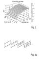
- a logarithmic curve for the estimated Mean Opinion Score (MOS) is fitted. Varying the packet error probability (PEP), this model results in the Mean Opinion Score (MOS) estimation surface of Fig. 3 for every user with a contracted rate of, for example 192 kbps.
- the fitting of the parameters a and b is, for example, done in a such a manner, that for a 192kbps ftp service as shown in Fig. 3, the maximum MOS of 4,5 is obtained when the user receives the subscribed bandwidth of 192 kbps without packet loss, and the minimum MOS of 1 is obtained when the user's actual bandwidth is 0 kbps.
- Encoding and decoding is performed with the H.264 JM 8.4 codec.
- the encoder is set to encode the first frame as an I-frame and all the following frames as P-frames.
- Nine slices per frame are assumed and in every frame, the macroblocks of a single slice are intra coded ( Figure 4A).
- Fig. 4B proposes the relation between the decoded average PSNR and user satisfaction measured with the metric Mean Opinion Score (MOS).
- Fig. 4C shows the average Mean Opinion Score (MOS) in case there are packet losses over the wireless channel. Every slice is encapsulated into one packet. Every % slice loss is simulated 1000 times with random slice loss patterns. The average decoded PSNR is computed over all the decoded frames. Slice or frame concealment is used and expected peak signal to noise (PSNR) and Mean Opinion Score (MOS) is measured.
- PSNR peak signal to noise
- MOS Mean Opinion Score
- U - requesting voice service V - file download and W - videoconference.
- the mobile users require different resources over the wireless channel. This depends on the channel code rate and the set of transmission rates that can be offered to the user. This is referred to as transmission policy.
- a user requesting voice service may be served with different voice codecs (G.711, Speex, iLBC (Internet Low Bit-rate Codec) or G.723.1.B in our example) and this data may be encoded with different channel code rate 1/2, 1/3, or 1/4 in our example. Every transmission policy gives different quality of service to the user and requires different amount of channel resources.
- T U is the set of transmission policies for voice service
- T V is the set of transmission policies for the file download service
- T W is the set of transmission policies for the video service.
- the Mean Opinion Score maxi-mation is to achieve maximum user satisfaction and fairness among the users.
- a decision variable for every transmission policy is defined - whether this user is served with a given transmission policy or not. Consequently these decision variables are of Boolean type, i.e. either the user transmits its information using this policy or not.
- the decision variables are u ij , where " i " denotes the i-th user and " j " denotes the transmission policies available for the voice users.
- the next step is to associate an expected user QoS defined with Mean Opinion Score (MOS).
- MOS Mean Opinion Score
- PEP packet error probability
- the objective function for a multi-user multi-application cross-layer optimization is defined in equation (4).
- a maximization of the sum of the QoS (MOS) perceived by every user in the multimedia wireless network has to be achieved.
- the parameter ⁇ is used to give higher priority to a given user and it is up to the network operator to choose its value.
- every user must be associated with a given transmission rate, channel code rate and modulation scheme.
- the decision variables u ij , v ij and w ij are of Boolean type, which means that the sum of all decision variables for a single user must be equal to one, see equations (5) to (7).
- the total available symbol rate for all the users is constrained to be less than the total symbol rate of the system. Every transmission policy has an associated symbol rate r ij and the sum of all individual symbol rates must be less or equal to the total symbol rate, see equation (8).
- a parameter ⁇ is inserted to ensure a fair allocation of resources.
- the optimizer tries to find a resource allocation, which maximizes the user satisfaction based on Mean Opinion Score (MOS), and this in general is the goal of every network operator. In this case there is a possibility that even though the system performance is maximized, a given user is not satisfied. This could be caused by low receiver SNR and the optimizer can decide to allocate the resources to the other users. This contradicts with the fairness that shall be offered to the users independent of their location.
- MOS Mean Opinion Score
- a scaling coefficient ⁇ based on the history of the user estimated QoS is selected.
- the user with the maximum perceived QoS has a scaling coefficient of one.
- the other users have scaling coefficients in the range [1; 4.5], because the denominator is also bounded in the interval [1; MaxMOS j ]. This is important for preserving the stability of the optimization algorithm. Since these ⁇ values scale the estimated Mean Opinion Score (MOS) for every transmission policy and the sum of the Mean Opinion Score (MOS) of all the users is maximized, the optimizer will try to assign transmission policies with high estimated Mean Opinion Score (MOS) to the users with higher ⁇ . This gives higher priority to the users, which have been receiving lower QoS up to the time of the optimization.
- a common network performance metric is the throughput of the system.
- the goal of the network operator is to maximize the network throughput.
- G ij R ij * 1 - PEP with R ij being the actual transmission rate.
- the objective function for such an optimization model is to maximize the sum of the rate allocated to all the users in the system and is given with equation (12).
- the optimizer is not aware of the user perceived quality. The assumption is that if a user receives more data rate, then he also has a higher QoS.
- Fig. 5A shows a diagram of a simulation set-up to compare the performance and user perceived quality using said exemplary embodiment of said inventive method compared to a throughput maximization method.
- the simulations are done with the following parameters: four voice users, two male voice users Voice1, Voice2 and two female voice users Voice3, Voice4 are used.
- the voice samples are 30 seconds long.
- the voice signal comes from the backbone network encoded with G.711 voice codec at 64kbps.
- the signal could be transcoded to 6.4 kbps with G.723.1 codec, 15.2 kbps with iLBC codec, 24.6 kbps with Speex or it can be transmitted without transcoding at 64 kbps.
- FTP1 Two users FTP1, FTP2 subscribed for file download using FTP. Both of them have subscribed for a service with maximum offered transmission rate of 192 kbps.
- the total available system rate is constant and three different cases are examined: 500 ksymbols/s, 700 ksymbols/s and 900 ksymbols/s.
- the supported modulation schemes are DBPSK (Differential BPSK) and DQPSK (Differential QPSK). Channel code rates of one-half, one-third, and one-forth are supported.
- step S570 after having determined the optimum transmission policies, represented by u ij , v ij , and w ij , and the respective transmission parameters for the application layer and the radio link layer (e.g. source codec, channel codec, modulation scheme) and the respective data rate available for each transmission, the base station transmits the transmission data (4 x voice, 2 x FTP, 1 x video) in a consecutive transmission interval based on the determined transmission policies (u ij , v ij , w ij ).
- the base station transmits the transmission data (4 x voice, 2 x FTP, 1 x video) in a consecutive transmission interval based on the determined transmission policies (u ij , v ij , w ij ).
- Fig. 7 shows the gain for the FTP users, FTP1, FTP2.
- the Mean Opinion Score (MOS) maximization approach outperforms again the throughput maximization approach.
- MOS Mean Opinion Score
- the continuous line arrows between the entities describe a first downlink scenario, wherein the mobile terminal MT transmits the transmission properties or derived packet error probability to the base station BS, i.e. performs the steps S510 to S530, or S510 to S520. Accordingly, the base station BS performs the steps S530 to S570 or S540 to S570.
- the priority coefficient will not only be user but also application specific, i.e. the service agreement defines not only a general application independent priority coefficient for the user but for each application a specific one.
- the user can subscribe to a service specific service level based on which an application priority coefficient, for example, for voice w ui , for FTP w vi , and for video w vi is derived.
- the inventive methods can be implemented in hardware or in software.
- the implementation can be performed using a digital storage medium, in particular a disk, DVD, or a CD having electronically readable control signals stored thereon, which cooperate with a programmable computer system such that the inventive methods are performed.
- the present invention is, therefore, a computer program product with a program code stored on a machine-readable carrier, the program code being operative for performing the inventive methods when the computer program product runs on a computer.
- the inventive methods are, therefore, a computer program having a program code for performing at least one of the inventive methods when the computer program runs on a computer.
Abstract
Description
- The present invention relates to the field of optimization of wireless network architectures and resource allocations.
- Optimization of network architectures is critical to achieve maximal network capacity and provide high quality services to the largest possible number of users. In common scenarios, multiple users share the wireless medium and engage in rather diverse applications such as video, voice, and FTP delivery. Optimizing allocation of resources across all users and applications maximizes the satisfaction of the users.
- So far cross-layer optimization has been applied only to single application systems. However, in practice multiple users sharing the wireless medium, e.g. in a cell, often run different applications simultaneously. User satisfaction translates into a different set of requirements for each type of application. Furthermore, the impact of losses on the user-perceived quality is highly application-dependent.
- The challenge of optimization across multiple applications has been treated mainly in the form of throughput maximization as described by V. Tsibonis, L. Georgiadis, L. Tassiulas, in "Exploiting wireless channel state information for throughput maximization," IEEE INFOCOM 2003,in the following referred to as [Tsi01], and by Xin Liu, E. Chong, N. Shroff, in "Transmission scheduling for efficient wireless utilization," IEEE INFOCOM 2001, in the following referred to as [Liu01].
- Maximizing throughput leads to optimum performance only for applications, which are insensitive to delay, and packet loss. Multimedia applications such as video and voice are highly sensitive to changes in data rate, delay, and packet losses. Even the importance of a packet changes dynamically depending on the history of previous packets. Due to these reasons, throughput maximization leads to performance, which is usually not optimal with respect to user perceived quality for multimedia applications.
- It is the object of the present invention to provide an apparatus and a method for determining transmission policies for a plurality of applications of different types considering user perceived quality for said applications.
- The object is achieved by an apparatus for determining transmission policies for a plurality of applications of different types according to
claim 1, a method for determining transmission policies for a plurality of applications of different types according toclaim 15, and a computer program according toclaim 16. - The invention provides an apparatus for determining transmission policies for a plurality of applications of different types based
- on a first transmission data associated to a first transmission being of a first transmission type,
- on a second transmission data associated to a second transmission being of a second transmission type,
- means for obtaining a first score within a common range, a said first score being based on an evaluation of said first transmission data in a first transmission type specific manner;
- means for obtaining a second score within the common range, said second score being based on an evaluation of said second transmission data in a second transmission type specific manner; and
- means for determining, based on said obtained scores, for said first and second transmission, a respective first and a second transmission policy, each defining one or more transmission parameters such that a sum of said first expected score and said second expected score is maximized.
- The present invention provides, furthermore, a method for determining transmission policies for a plurality of transmissions of different types based
- on a first transmission data associated to a first transmission being of a first transmission type,
- on a second transmission data associated to a second transmission being of a second transmission type,
- obtaining a first score with a common range, said first score being based on an evaluation of said first transmission data in a first transmission type specific manner;
- obtaining a second score within the common range, said second score being based on an evaluation of said second transmission data in a second transmission type manner; and
- determining based on said assigned first and second score, for the first and second transmission a respective first and second transmission policy defining one or more transmission parameters such that a sum of a first expected score and second expected score for a consecutive transmission interval is maximized.
- Furthermore, the present invention provides a computer program having a program code for performing the inventive method according to
claim 15, when the program runs on a computer. - The present invention is based on the finding that jointly optimizing the system for different users and applications requires: First, defining a common metric that quantifies the satisfaction of the user for the service delivery and, second, mapping network and/or application parameters onto this metric.
- Said common metric is also referred to as score within this description, wherein said score is defined for a common range with a common minimum score and a common maximum score, wherein common is defined in the sense of being common for all transmissions and transmission types.
- The invention provides a cross-layer optimization framework, the aim of which is to maximize user satisfaction. The challenge of the inventive approach lies in the problem of quantifying user satisfaction with respect to system parameters such as throughput, delay, packet error rate, etc.
- In a preferred embodiment a Mean Opinion Score (MOS) is used as said score and common performance metric for the optimization. Despite the fact that the following discussion will be based on the Mean Opinion Score (MOS) it should be noted that the present invention comprises the usage of other scores; other scores with a common range different to the Mean Opinion Score (MOS) which consider the user perceived quality of transmission are also possible.
- The Mean Opinion Score (MOS) was originally proposed for voice quality assessment and provides a numerical measure of the quality of human speech at the destination end of the circuit. The scheme uses subjective tests (opinionated scores) that are mathematically averaged to obtain a quantitative indicator of the system performance. To determine Mean Opinion Score (MOS), a number of listeners rate the quality of test sentences read aloud over the communications circuit by a speaker. A listener gives each sentence a rating as follows: (1) bad; (2) poor; (3) fair; (4) good; (5) excellent. The Mean Opinion Score (MOS) is the arithmetic mean of all the individual scores, and can range from 1 (worst) to 5 (best).
- For other applications, such as video, web browsing and file download, the same scale of Mean Opinion Score (MOS), which reflects the user perceived quality of the application is used. This now enables one to optimize across applications using a common optimization metric. The objective function can be chosen, e.g., to be the average Mean Opinion Score (MOS) of all the users or of all transmissions:

where F(x̃) is the objective function with the cross-layer parameter tuple x̃ ∈ X̃ . X̃ is the set of all possible parameter tuples abstracted from the protocol layers. wk is the relative importance of the user or transmission as determined by the service agreement between the user and the service provider. - The decision of the means for determining, in the following also referred to as optimizer, can be expressed as:

where x̃ opt is the optimum parameter tuple, which maximizes the objective function. Once the optimizer has selected the optimal values of the parameters, it distributes them to all the individual layers, which are responsible for translating them back into actual modes of operation. - Using scores with the common scale or common range - having the same minimum score and the same maximum score - as the optimization parameter provides various advantages. First, as the user perceived quality of the service or application is now provided on the same scale or range, which is common to all transmission or application types, one can take advantage now of the diversity at the application layer, for example, by using different source codecs (CODEC = Encoding/Decoding), in addition to the diversity at the physical layer, for example, by using different channel codecs and different modulation schemes. Thus, all possible transmission scenarios comprising all applications and their possible transmission parameters can be calculated and compared to each other based on transmission scenario specific scores. Said scenario specific score can be the sum of all said "tranmision individual" scores or the arithmetic mean of all said "transmission individual" scores. The task of the means for determining or the optimizer is now to maximize the sum or the arithmetic mean of all individual treating all application or transmission "equally". Abstracting, for example, the application and physical layer parameters to said user perceived quality score provides an effective means to optimize the allocation of network or radio resources and at the same time taking into account real-time and latency requirements of applications like voice and video streaming. Second, using a score within a common range facilitates to prioritize specific users or applications and/or to provide for a fair allocation of network and radio resources, for example, based on the history of scores for each application or user.
- A more detailed description of a basic cross-layer optimization approach, the principle of parameter abstraction and the formulation of objective functions for multi-user cross-layer optimization is provided by Y. Peng, S. Khan, E. Steinbach, M. Sgroi, W. Kellerer, in "Adaptive resource allocation and frame scheduling for wireless multi-user video streaming," IEEE International Conference on Image Processing, ICIP'05, Genova, Italy, September 2005, in the following referred to as [Pen01], and by S. Khan, M. Sgroi, E. Steinbach, and W. Kellerer, "Cross-layer optimization for wireless video streaming - performance and cost," IEEE International Conference on Multimedia & Expo, ICME 2005, Amsterdam, July 2005, in the following referred to as [Kha01].
- Preferred embodiments of the present invention are described in detail with respect to the following figures:
- Fig. 1A
- shows an embodiment of an inventive apparatus;
- Fig. 1B
- shows an exemplary network scenario with a base station comprising an inventive apparatus;
- Fig. 1C
- shows a diagram for a multi-application, cross-layer optimization;
- Fig. 1D
- shows a diagram explaining the relation between the Mean Opinion Score (MOS) and user satisfaction;
- Fig. 2
- shows a diagram depicting a Perceptual Evaluation of Speech Quality (PESQ) based Mean Opinion Score (MOS) versus packet loss for different voice codecs;
- Fig. 3
- shows a diagram of a file transfer protocol (FTP) user Mean Opinion Score (MOS) estimation surface versus packet loss and data range;
- Fig. 4A
- shows an H.264 based exemplary encoding of video sequences for conversational video applications;
- Fig. 4B
- shows a diagram depicting a video user Mean Opinion Score (MOS) versus peak signal to noise ratio (PSNR);
- Fig. 4C
- shows a diagram depicting a video user Mean Opinion Score (MOS) versus slice losses for a foreman video sequence;
- Fig. 5A
- shows a diagram of a simulation set-up for the invention;
- Fig. 5B
- shows an embodiment of said inventive method used for the simulation set-up as shown in Fig. 5A.
- Fig. 6
- shows a diagram of Mean Opinion Scores (MOS) of voice users based on the simulation set-up according to Fig. 5A;
- Fig. 7
- shows a diagram of Mean Opinion Scores (MOS) of file transfer protocol (FTP) users of the simulation set-up according to Fig. 5A;
- Fig. 8
- shows a diagram of Mean Opinion Scores (MOS) of video conferencing for the simulation set-up according to Fig. 5A;
- Fig. 9
- shows a Mean Opinion Score (MOS) gain per user for a simulation set-up according to Fig. 5A with a system symbol rate of 500 k symbols/s;
- Fig. 10
- shows a diagram of Mean Opinion Score (MOS) gain per user for a simulation set-up according to Fig. 5A with a system symbol rate of 700 k symbols/s; and
- Fig. 11
- shows a diagram of a Mean Opinion Score (MOS) gain per user for a simulation set-up according to Fig. 5A with a system symbol rate of 900 k symbols/s.
- Fig. 1A shows an embodiment of an
inventive apparatus 100 comprising ameans 110 for obtaining a first score within a common range, ameans 120 for obtaining a second score within the common range and ameans 130 for determining a transmission policy. The means 110 for obtaining afirst score 112 within a common range, saidfirst score 112 being based on an evaluation of a first transmission data associated to a first transmission being of a first transmission type, wherein the evaluation is performed in a first transmission type specific manner. The means 110 for obtaining saidfirst score 112 outputs saidfirst score 112 to said means 130 for determining.Means 120 for obtaining asecond score 122 within the common range is operative to obtain saidsecond score 122 and to output saidsecond score 122 to themeans 130 for determining, wherein saidsecond score 122 is based on an evaluation of a second transmission data associated to a second transmission being of a second transmission type, wherein the evaluation is performed in a second transmission type specific manner. - Said means 130 for determining is operative to receive said
first score 112 and saidsecond score 122 and to determine, based on saidscores second transmission policy 132, wherein each transmission policy defines one or more transmission parameters such that a sum of expected scores is maximized. - In one embodiment of the
inventive apparatus 100 the means for obtaining 110, 120 are operative to use one or more respective expected scores of previous maximization steps for deriving said first or second score. In this case the apparatus is adapted to operate without feedback of other entities, e.g. receivers. - In another embodiment of the
inventive apparatus 100 the means for obtaining 110, 120 comprise ameans first score 112 or saidsecond score 122 from an apparatus the first or second transmission data has been transmitted to, wherein said means means 114, 124 for receiving are optional and are shown in broken lines in Fig. 1A. - In a further embodiment of the
inventive apparatus 100 said means for obtaining 110, 120 comprise arespective means first score 112 orsecond score 122 from afirst transmission property 118 or second measuredtransmission property 128 which, for example, can be received from an apparatus the first or second transmission data has been transmitted to, wherein said means means 116, 126 for receiving are optional and are shown in broken lines in Fig. 1A. The measuredtransmission properties - In an alternative embodiment of the
inventive apparatus 100 said means 110, 120, 130 can be merged to one means. - Alternative embodiments of the
inventive apparatus 100 can comprise more than twomeans - Another embodiment of the
inventive apparatus 100 may comprise instead of twoseparate means - Fig. 1B shows an exemplary network scenario with a base station 160, a
first terminal 170 and asecond terminal 180. The base station 160 comprises aninventive apparatus 100 and anantenna 162, which is connected to theinventive apparatus 100. - Fig. 1B shows a scenario wherein first transmission data associated to said first transmission being of a first transmission type is transmitted between the
first terminal 170 and the base station 160, either on-link 170D or up-link 170U or both. Accordingly, second transmission data associated to a second transmission being of a second transmission type is transmitted between thesecond terminal 180 and the base station 160, either down-link 180D or up-link 180U, or both. - In the following different scenarios for obtaining said score will be discussed based on the transmission between said
first terminal 170 and said base station 160, wherein the following explanations can also be applied to the second transmission between thesecond terminal 180 and said base station 160 or any other terminal. - In a downlink scenario, said base station 160 transmits first transmission data downlink 170D to the
first terminal 170. Thefirst terminal 170 receives the first transmission data and can measure, for example, the actual signal to noise ratio (SNR) of the received tranmission data. - The
first terminal 170 can be operative, for example, to transmituplink 170U the transmission property of the received first transmission data, i.e. the actual signal to noise ratio of the received first transmission data, to said base station, or to be more precise, to said means 110 for obtaining a first score, or can be operative to derive said first score itself from said first transmission property and transmit said first score up-link 170U to said base station 160 or means 110 for obtaining a first score. - In an up-link scenario, the
first transmitter 170 transmits first transmission data uplink 170U to the base station 160. The base station 160, or to be more precise themeans 110 for obtaining can itself determine such transmission property of the first transmission data and directly derive thereof thefirst score 112. - Based on the obtained scores, for example, the first and
second score means 130 determines a respective first and second transmission policy (132.1; 132.2) and defines for the first and the second transmission said one or more transmission parameters such that said sum of said first and said second expected score is maximized for a transmission in a consecutive transmission interval. - For the afore-mentioned downlink transmission scenario 170D the base station 160 will transmit said first transmission data in said consecutive transmission interval based on the determined transmission parameters.
- For the latter scenario, the
uplink scenario 170U, the base station 160 transmits said determined first transmission policy downlink to thefirst terminal 170, which will then transmit first transmission data in a consecutive transmission interval based on said first transmission policy received from said base station 160. - Said transmission properties can, for example, be transmitted from said
first terminal 170 using a dedicated signalling channel or can be "piggy-backed" onto, for example, acknowledge messages. - The term transmission data associated to a transmission being of a certain transmission type comprises transmission of data of applications like voice, hyper-text transfer protocol (HTTP), file transfer protocol (FTP), video and music streaming and other applications, but also comprises the transmission of signalling data or any other data, for example, used to control the network.
- In typical wireless or mobile network scenarios, base stations control the radio resources within their cells, thus, said inventive apparatus for determining transmission policies for a plurality of applications of different types is-typically implemented in said base stations. Nevertheless, in alternative scenarios like ad-hoc networks, any other device, for example, a communication device, may be charged with the task to and/or optimize the radio resources. For such cases, said inventive apparatus can also be implemented in other devices for an optimization or maximization of the user perceived quality of services and applications.
- In the following, it will be shown that the inventive optimization framework achieves significant improvement in terms of user perceived quality for an exemplary implementation with three application types, with real-time voice, file download and video conferencing, as shown in Fig. 1C.
- Fig. 1C shows a diagram for an exemplary multi-application, cross-layer optimization set-up, comprising an
inventive apparatus 100, in Fig. 1C referred to as cross-layer optimizer, which receivestransmission properties - The cross-layer optimizer, i.e.
inventive apparatus 100, is operative to derive said score, in Fig. 1C a Mean Opinion Score (MOS), from said transmission properties based on predefined look-up tables or predefined algorithms. Theinventive apparatus 100 according to Fig. 1C uses a look-up table 192 for deriving said Mean Opinion Score for voice based on said packet error probability (PEP), uses an look-up table 194 for deriving said Mean Opinion Score for FTP based on random packet loss rate (%) and data rate (kbps), and uses a video lookup-table 196 for deriving a Mean Opinion Score for video based on a packet error probability (PEP). The look-tables 192, 194, and 196, or in more general the relation between the Mean Opinion Score and the transmission properties or parameters will be explained later in more detail. - Based on the obtained scores for each voice transmission, each FTP transmission and each video transmission said means for determining of the inventive apparatus determines for each of the voice transmissions, FTP transmissions, and video transmissions a
respective transmission policy 132, and distributes the decision, i.e. the optimum transmission policy to various layers, in Fig. 1C to the application layer and the radio link layer. - The traditional method of determining voice quality is to conduct subjective tests with panels of human listeners. The results of these tests are averaged to give Mean Opinion Score (MOS) but such tests are expensive and are impractical for online voice quality assessment. For this reason the ITU has standardized a new model, Perceptual Evaluation of Speech Quality (PESQ), an algorithm that predicts with high correlation the quality scores that would be given in a typical subjective test. This is done by making an intrusive test and processing the test signals through PESQ.
- PESQ measures one-way voice quality: a signal is injected into the system under test, and the degraded output is compared by PESQ with the input (reference) signal. Mapping between Mean Opinion Score (MOS) and user satisfaction is presented in Figure 1D.
- The PESQ algorithm is computationally too expensive to be used in real-time scenarios. To solve this problem a model is proposed to estimate Mean Opinion Score (MOS) with a few parameters, which are easy to compute - packet error probability and available bit rate. The available rate determines the voice codec that can be used. In Figure 2 experimental curves for Mean Opinion Score (MOS) estimation as a function of packet error probability for different voice codecs are shown. The curves are drawn using an average over a large number of voice samples and channel realizations (packet loss patterns). These curves can be stored in the base station for every codec that is supported. If transcoding from an unsupported codec is required, such curves can be signalled to the base station as side information.
- To estimate FTP user satisfaction a logarithmic MOS-throughput relationship as introduced by A. Saliba, M. Beresford, M. Ivanovich and P. Fitzpatrick, in "Measuring Quality of Service in an Experimental Wireless Data Network," Australian Telecommunication Networks and Applications Conference, Melbourne, Australia, December 2003, in the following [Sa101], is used. It is assumed that every user has subscribed for a given data rate and his satisfaction is characterized by the real rate he receives. The Mean Opinion Score (MOS) is estimated based on the current rate offered to the user by the system and the packet loss rate:

- If a user has subscribed for bandwidth R and receives bandwidth R, then in case of no packet loss his satisfaction on the Mean Opinion Score (MOS) scale should be maximum, i.e. 4.5. On the other end, a minimum bandwidth is defined that can be offered to the user and assign to it a Mean Opinion Score (MOS) value of 1. Using the parameters a and b, a logarithmic curve for the estimated Mean Opinion Score (MOS) is fitted. Varying the packet error probability (PEP), this model results in the Mean Opinion Score (MOS) estimation surface of Fig. 3 for every user with a contracted rate of, for example 192 kbps.
- The fitting of the parameters a and b is, for example, done in a such a manner, that for a 192kbps ftp service as shown in Fig. 3, the maximum MOS of 4,5 is obtained when the user receives the subscribed bandwidth of 192 kbps without packet loss, and the minimum MOS of 1 is obtained when the user's actual bandwidth is 0 kbps. The actual parameters were chosen as follows: a = 2.6902 and b = 0,2452/kbps.
- To support video-conferencing or real-time video in the wireless multimedia network a simple model for evaluating the quality of a video material is introduced. It is assumed that all the information about the distortion caused by a slice loss is known and the Peak Signal to Noise Ratio (PSNR) for different slice loss percentages is evaluated. The model is constructed for the Foreman video sequence, a standard video sequence for benchmarks, but can be easily extended for different videos.
- Encoding and decoding is performed with the H.264 JM 8.4 codec. The encoder is set to encode the first frame as an I-frame and all the following frames as P-frames. Nine slices per frame are assumed and in every frame, the macroblocks of a single slice are intra coded (Figure 4A).
- This results in a higher bit-rate, but also gives higher resilience against lost packets (slices). If a slice is lost, the effect of this loss will be washed out after a maximum of nine frames. Resulting average PSNR over all 400 frames for zero percent packet loss is 35.30 dB in our experiment.
- Fig. 4B proposes the relation between the decoded average PSNR and user satisfaction measured with the metric Mean Opinion Score (MOS). Fig. 4C shows the average Mean Opinion Score (MOS) in case there are packet losses over the wireless channel. Every slice is encapsulated into one packet. Every % slice loss is simulated 1000 times with random slice loss patterns. The average decoded PSNR is computed over all the decoded frames. Slice or frame concealment is used and expected peak signal to noise (PSNR) and Mean Opinion Score (MOS) is measured.
- For the application-driven cross-layer optimization three sets of users are defined: U - requesting voice service, V - file download and W - videoconference. Depending on the service, the mobile users require different resources over the wireless channel. This depends on the channel code rate and the set of transmission rates that can be offered to the user. This is referred to as transmission policy. For example a user requesting voice service may be served with different voice codecs (G.711, Speex, iLBC (Internet Low Bit-rate Codec) or G.723.1.B in our example) and this data may be encoded with different
channel code rate 1/2, 1/3, or 1/4 in our example. Every transmission policy gives different quality of service to the user and requires different amount of channel resources. - Sets of transmission policies are created for every service. TU is the set of transmission policies for voice service, TV is the set of transmission policies for the file download service, and TW is the set of transmission policies for the video service.
- The goal of this optimization, the Mean Opinion Score maxi-mation is to achieve maximum user satisfaction and fairness among the users. For every user, depending on the service, a decision variable for every transmission policy is defined - whether this user is served with a given transmission policy or not. Consequently these decision variables are of Boolean type, i.e. either the user transmits its information using this policy or not. For the voice users, the decision variables are uij, where "i" denotes the i-th user and "j" denotes the transmission policies available for the voice users. The next step is to associate an expected user QoS defined with Mean Opinion Score (MOS).
- Every user in the wireless network has a different position and mobility, which results in variable receiver SNR. Based on the receiver SNR, an estimation on the packet error probability (PEP) can be obtained for different modulation schemes (BPSK-Binary Phase Shift Keying and QPSK-Quartenary Phase Shift Keying) and different channel code rates, i.e. for all transmission policies as described by M. T. Ivrlac, "Parameter selection for the Gilbert-Elliott model," Technical Report TUM-LNS-TR-03-05, Institute for Circuit Theory and Signal Processing, Munich University of Technology, May 2003, in the following referred to as [Ivr01]. A channel realization is generated and the estimation of the packet error probability (PEP) is performed for all the transmission policies given the particular received SNR.
- The objective function for a multi-user multi-application cross-layer optimization is defined in equation (4). A maximization of the sum of the QoS (MOS) perceived by every user in the multimedia wireless network has to be achieved. The parameter λ is used to give higher priority to a given user and it is up to the network operator to choose its value.

- Subject to:


- In the described example, every user must be associated with a given transmission rate, channel code rate and modulation scheme. The decision variables uij, vij and wij are of Boolean type, which means that the sum of all decision variables for a single user must be equal to one, see equations (5) to (7). The total available symbol rate for all the users is constrained to be less than the total symbol rate of the system. Every transmission policy has an associated symbol rate rij and the sum of all individual symbol rates must be less or equal to the total symbol rate, see equation (8).
- In a preferred embodiment a parameter λ is inserted to ensure a fair allocation of resources. The optimizer tries to find a resource allocation, which maximizes the user satisfaction based on Mean Opinion Score (MOS), and this in general is the goal of every network operator. In this case there is a possibility that even though the system performance is maximized, a given user is not satisfied. This could be caused by low receiver SNR and the optimizer can decide to allocate the resources to the other users. This contradicts with the fairness that shall be offered to the users independent of their location. To solve this problem a scaling coefficient λ based on the history of the user estimated QoS is selected. On every rate allocation procedure, the user with maximum average of the estimated QoS for the previous steps is found assuming that one is at rate allocation step "j" and K number of users are in the system, the value of the maximum perceived QoS by a single user is found by


- The λ for every user or transmission is calculated with

- The user with the maximum perceived QoS has a scaling coefficient of one. The other users have scaling coefficients in the range [1; 4.5], because the denominator is also bounded in the interval [1; MaxMOSj]. This is important for preserving the stability of the optimization algorithm. Since these λ values scale the estimated Mean Opinion Score (MOS) for every transmission policy and the sum of the Mean Opinion Score (MOS) of all the users is maximized, the optimizer will try to assign transmission policies with high estimated Mean Opinion Score (MOS) to the users with higher λ. This gives higher priority to the users, which have been receiving lower QoS up to the time of the optimization.
- A common network performance metric is the throughput of the system. Traditionally, the goal of the network operator is to maximize the network throughput. By throughput the effective rate (goodput) Gij of a given user i at time j is considered:

- For throughput maximization same set of decision variables as in equation (4)-(8) is used. The difference is the absence of the scaling parameter λ. Here one does not need scaling of the allocated transmission rate, because the transmission rates required by different applications are not comparable.

- Subject to:


- Fig. 5A shows a diagram of a simulation set-up to compare the performance and user perceived quality using said exemplary embodiment of said inventive method compared to a throughput maximization method. The simulations are done with the following parameters: four voice users, two male voice users Voice1, Voice2 and two female voice users Voice3, Voice4 are used.
- The voice samples are 30 seconds long. The voice signal comes from the backbone network encoded with G.711 voice codec at 64kbps. In the base station BS, following the optimization output, the signal could be transcoded to 6.4 kbps with G.723.1 codec, 15.2 kbps with iLBC codec, 24.6 kbps with Speex or it can be transmitted without transcoding at 64 kbps.
- Two users FTP1, FTP2 subscribed for file download using FTP. Both of them have subscribed for a service with maximum offered transmission rate of 192 kbps.
- One user video requests video-conferencing. The video sequence used is Foreman, encoded with H.264 encoder. The frame sequence is I-P-P-P-...-P, which is the appropriate format for real-time video.
- The total available system rate is constant and three different cases are examined: 500 ksymbols/s, 700 ksymbols/s and 900 ksymbols/s. The supported modulation schemes are DBPSK (Differential BPSK) and DQPSK (Differential QPSK). Channel code rates of one-half, one-third, and one-forth are supported.
- Because of the users' mobility, their received SNR for every optimization step is drawn randomly, according to the uniform distribution from a given interval. The system is active for 30 seconds and it is assumed that the average channel characteristics remain constant for 1.2 seconds, which results in 25 optimization loops.
- In order to obtain the relationship between SNR and PEP, a rayleigh fading channel is simulated. For a particular combination of signal-to-noise ratio (SNR), modulation scheme (DBPSK or DQPSK) and channel coding rate (1/2, 1/3 or 1/4) the transmission of one million symbols over the channel is simulated. For this particular setting the residual Bit-Error-Rate (BER) after reception of the symbols at the receiver is computed. Based on the Bit error rate (BER) the packet error probability (PEP) is computed, using the application layer packet size. For the simulations 640 bits for the G.711 encoded packets, 304 bits for the iLBC encoded packets, 496bits for SPEEX packets, 192bits for G.723.1 packets, 640 bits for the FTP packets and 900bits for the video packets are used.
- The scaling parameter λ is calculated based on the expected MOS (not the actual MOS) of previous optimization steps. Thus, no feedback of appliction layer quality from the mobile terminals or users to the base station is assumed.
- For the voice users, the signal samples are partitioned into 1.2 seconds and every sample is encoded with a voice codec, given from the optimization algorithm. At the end of the optimization loops, these voice samples are assembled into a single file and the perceived quality (MOS) is computed by comparing the original signal and the distorted one.
- For the video user, if a slice is lost, it is not written in the bit stream, which tells the decoder to invoke the error concealment algorithm. The PSNR of every frame and the resulting average PSNR are computed. The average PSNR is converted to Mean Opinion Score (MOS) value using the relationship shown in Fig. 4B.
- Fig. 5B shows a flow chart of an exemplary embodiment of said inventive method used for the simulation set-up as shown in Fig. 5A. Fig. 5B shows seven steps S510 to S570, which are performed repeatedly for the simulation.
- In step S510 the seven mobile terminals - each "user" has one terminal and performs one application - receive the first to seventh transmission data (application data: 4 x Voice, 2 x FTP, 1 x Video) associated to the first to seventh transmission (applications: 4 x Voice, 2 x FTP, 1 x Video) being of a first to third transmissionion type (application type: Voice, FTP, Video).
- In a consecutive step S520, the mobile terminals derive the transmission properties of the received transmission data for each single transmission independently: transmission rate, packet loss rate and/or signal to noise ratio. Based thereon the expected MOS for the different applications can be determined.
- In step S530 the packet error probability (PEP) is derived based on the transmission properties of each transmission as described in [Ivr01]. This step can be either performed by the mobile terminal or the base station.
- In step S540 the user perceived quality score (Mean Opinion Score MOSij) is obtained or derived based on the transmission properties on a transmission specific manner, i.e. for voice based on the packet error probability according to Fig. 2 or more generally expressed according to a look-up table 192 according to Fig. 1C, i.e. for FTP based on the packet error probability or packet loss and the data rate according to a look-up table according to Fig. 3 or 194 in Fig. 1C, i.e. for video based on packet error probability defined in a look-up table according to Fig. 4B or 196 according to Fig. 1C.
- In step S550 the base station BS calculates the scaling or fairness coefficient λkj (or in equation (4) λui, λvi, λwi) for each transmission based on the historical scores (MOSki) according to the equations (9) and (10).
- In step S560 the base station BS maximizes the sum of expected scores (E[MOSij]) to determine the optimum transmission scenario, i.e. the optimum combination of "individual" transmission policies uij for voice, vij for FTP, and wij for video for each transmission.
- In step S570, after having determined the optimum transmission policies, represented by uij, vij, and wij, and the respective transmission parameters for the application layer and the radio link layer (e.g. source codec, channel codec, modulation scheme) and the respective data rate available for each transmission, the base station transmits the transmission data (4 x voice, 2 x FTP, 1 x video) in a consecutive transmission interval based on the determined transmission policies (uij, vij, wij).
- After step S570,
step 510 is again performed based on the newly transmitted data. - In the following a comparison between both investigated optimization approaches is done. The set-up described in the previous section is used and each simulation is run 600 times.
- Fig. 6 presents the improvement of the voice user satisfaction for voice users Voice1 to Voice4 between the Mean Opinion Score (MOS) maximization, i.e. said embodiment of said inventive method according to Fig. 5A, and throughput maximization rate allocation schemes. At a total system rate of 500 ksymbols/s the average gain in terms of Mean Opinion Score (MOS) is 0.85. At 700 ksymbols/s the gain is still significant - 0.6 and for 900 ksymbols/s it is around 0.4. The Mean Opinion Score (MOS) maximization scheme results in small improvement with the increase of the available transmission rate. This means that in case of scarce resources, it gives a good quality to the users.
- Fig. 7 shows the gain for the FTP users, FTP1, FTP2. The Mean Opinion Score (MOS) maximization approach outperforms again the throughput maximization approach. Here the gain is lower, but it is still significant. For 500 ksymbols/s the gain is 0.7 MOS on the average, for 700 ksymbols/s it is 0.45 and for 900 ksymbols/s it is 0.3.
- Fig. 8 shows the video-conferencing quality improvement for video user Video. The gains in terms of MOS are similar to the case of the voice users Voice1 to Voice4 in Fig. 6 and with the increase of the available transmission rate the gain decreases.
- For all the cases presented in the figures 6 - 8, the MOS maximization has the advantage of offering lower spread of the QoS offered to the users. For example if one considers Fig. 6 for the case of a total system symbol rate of 500 ksymbols/s, the resulting MOS in 90 % of the cases for the throughput maximization varies between MOS of 2 and 3.5, i.e. spread of 1.5 MOS. On the other hand the MOS maximization results in MOS variations between 3.4 and 4.1, i.e., a spread of only 0.7 MOS.
- In Figs. 9 to 11 the voice users Voice1 to Voice4 are referred to as
Voice users 1 to 4, the FTP users FTP1, FTP2 are referred to asFTP user 1,FTP user 2, and the video user Video asVideo user 1. - Figures 9 - 11 present the gain per user in the system. The curves are produced as a difference between the MOS computed with MOS maximization and throughput maximization. Starting with a system symbol rate of 500 ksymbols/s (Fig. 9), in 50% of the simulations, the average gain for all users is 0.8. Exceptions are the video-conferencing user Video, who has even higher MOS gain and the
FTP user 2, who has a lower gain. In the system with 700 ksymbols/s (Fig. 10) there are cases (1% for the user having video-conferencing) where the throughput maximization gives better results for a given user. This is even more visible in the case with system symbol rate 900 ksymbols/s (Fig. 11) when two users (the user having videoconferencing and the fourth voice user) have better performance in case of throughput maximization (10% of the cases). The mentioned users are the ones with the best channel with respect to received SNR. In case of MOS maximization, the optimizer takes resources from them to increase the Mean Opinion Score (MOS) of the users who have worse channels. - On the right hand side of the flow chart in Fig. 5B exemplary information flows between entities performing the task are depicted, wherein MT (Mobile Terminal) stands for entities like mobile terminals or users (
e.g. Voice 1 toVoice 4, FTP1, FTP2, Video in Fig. 5A) and BS (Base Station) stands for the entities like base stations being responsible for the resource allocation (e.g. BS in Fig. 5A). - The continuous line arrows between the entities describe a first downlink scenario, wherein the mobile terminal MT transmits the transmission properties or derived packet error probability to the base station BS, i.e. performs the steps S510 to S530, or S510 to S520. Accordingly, the base station BS performs the steps S530 to S570 or S540 to S570.
- The broken line arrows between the entities describe a second downlink scenario, wherein the mobile terminal MT transmits the score to the base station BS, i.e. performs the steps S510 to 540. Accordingly, the base station BS performs only the steps S540 to S570.
- The dotted line arrows describe an uplink scenario. An additional step after step S560 is required, at which the base station BS, after having determined the optimum transmission policies, transmits to each of the mobile terminals MT the respective transmission policy uij, vij, wij, based on which each of said mobile terminals then transmits the transmission data in the consecutive transmission interval.
- Typically, preferred embodiments will be implemented such that only a minimum of the processing is done by mobile terminals, because they typically only have limited processing power compared to base stations, and perform the processing power intensive parts or steps at the base station. Thus, in a preferred scenario, the mobile terminal MT will only perform the steps S510 and S520, transmit the transmission properties to a base station BS and the base station BS performs the remaining steps S530 to S570.
- Depending on the application or transmission type, the capability of mobile terminals MT to perform further steps, for example, S530 or S540, the decision about which entity performs which steps may be even done dynamically, for example, for each transmission.
- Despite the fact that Fig. 5A only shows a down-link scenario, the invention is not limited to down-link scenarios, as described before, but can also be used for uplink scenarios and mixed uplink/downlink scenarios, for any number of users, applications and application types and also for users performing more than one application at the same time.
- In another embodiment of the present invention a priority coefficient wk is used, the priority coefficient Wk representing the relative importance of the user as determined, for example, by a service agreement between the user and the service provider, wherein k = 1..K is one of the K users. In another embodiment, the priority coefficient will not only be user but also application specific, i.e. the service agreement defines not only a general application independent priority coefficient for the user but for each application a specific one. The user can subscribe to a service specific service level based on which an application priority coefficient, for example, for voice wui, for FTP wvi, and for video wvi is derived. The priority coefficient can be either used instead of the fairness or scaling coefficient λij or in combination with the scaling coefficient λij. Equation (17) shows the optimization function with a priority coefficient:

- Alternatively to the scenario described in Fig. 5A, the inventive apparatus for determining transmission policies can also be usefully implemented in any other device, which is responsible or is allowed to take responsibility for allocating network or radio resources.
- Despite the fact that the afore-mentioned description focuses on parameters from the application layer and radio link layer, as shown in Fig. 1C, alternative embodiments of the present invention may also comprise parameters from other layers, for example, the transport layer, or network layer.
- To summarize the afore-mentioned discussion, the present invention provides an apparatus and method for determining transmission policies and a system that allows optimizing allocation of wireless network resources across multiple types of applications. In a preferred embodiment, the present invention proposes an optimization scheme based on the Mean Opinion Score (MOS) as the user perceived quality score and unifying or common metric. The Mean Opinion Score quantifies the satisfaction of the users for the service delivery. The invention can be used in any system dealing with the delivery of services over mobile communication networks.
- The present invention will be of benefit to increase network capacity, i.e. provide services to a large number of users simultaneously, and improve the user perceived quality of service (QoS).
- Using Mean Opinion Score (MOS) as the optimization parameter is helpful in different respects. First, this enables one to give an easy and straightforward measure of fairness. Second, as one is now on the same scale of application layer performance, this allows taking advantage of diversity at the application layer in addition to the diversity at the physical layer. In addition, this is likely to open up the possibility of a highly flexible framework for cross-layer optimization, such as adaptation of the application to the transport, network, data-link, and physical layer characteristics (bottom-up approach) and the adaptation of the physical, data link or network layers to the application requirements (top-down approach). In particular, the invention is of great benefit to the network operator as it allows improving user-perceived QoS and increasing network capacity by maximizing the number of users that can be serviced simultaneously.
- Depending on certain implementation requirements of the inventive methods, the inventive methods can be implemented in hardware or in software. The implementation can be performed using a digital storage medium, in particular a disk, DVD, or a CD having electronically readable control signals stored thereon, which cooperate with a programmable computer system such that the inventive methods are performed. Generally, the present invention is, therefore, a computer program product with a program code stored on a machine-readable carrier, the program code being operative for performing the inventive methods when the computer program product runs on a computer. In other words, the inventive methods are, therefore, a computer program having a program code for performing at least one of the inventive methods when the computer program runs on a computer.
Claims (16)
- Apparatus for determining transmission policies for a plurality of applications of different types basedon first transmission data associated to a first transmission being of a first transmission type,on second transmission data associated to a second transmission being of a second transmission type,comprising:means (110) for obtaining a first score (112) within a common range, a said first score being based on an evaluation of said first transmission data in a first transmission type specific manner;means (120) for obtaining a second score (122) within the common range, said second score being based on an evaluation of said second transmission data in a second transmission type specific manner; andmeans (130) for determining, based on said obtained scores (112; 122), for said first and second transmission, a respective first (130.1) and second transmission policy (130.2), each defining one or more transmission parameters such that a sum of a first expected score and a second expected score is maximized.
- Apparatus according to claim 1, wherein said means (110; 120) for obtaining comprises a means (116; 126) for deriving said first (112) or second score (122) from one or more actual or expected first (118) or second transmission properties (128).
- Apparatus according to claim 1, wherein said means (110; 120) for obtaining comprises a means (114; 124) for receiving said first or second score (112; 122) from a means the first or second transmission data has been transmitted to.
- Apparatus according to claim 2 or 3, wherein said means (110; 120) for deriving is operative to use a signal to noise ratio (SNR), a packet error probability (PEP) or data rate as first or second transmission property (118; 128).
- Apparatus according to one of the claims 2 to 4, wherein said means (130) for deriving is operative to derive said first or second score (112; 122) from a first or second transmission property (118; 128) based on a predefined look-up table (192, 194, 196) or predefined algorithm.
- Apparatus according to one of the claims 1 to 5, wherein said means (130) for determining is operative to determine said first and second transmission policy (132.1, 132.2) by defining a source coding type as a first or second transmission parameter (132.1; 132.2).
- Apparatus according to one of the claims 1 to 6, wherein said means (130) for determining is operative to determine said first and second transmission policy (132.1, 132.2) by defining a channel coding type as a first or second transmission parameter (132.1; 132.2).
- Apparatus according to one of the claims 1 to 7, wherein said means (130) for determining is operative to determine said first and second transmission policy (132.1, 132.2) by defining a modulation scheme type as first or second transmission parameter.
- Apparatus according to one of the claims 1 to 8, wherein said means (130) for determining is operative to determine said first or second transmission policy (132.1, 132.2) based on a following function:

wherein E [MOSij] is said respective expected score, wherein uij, is a decision variable of a first decision variable type each representing a possible first transmission policy, and wherein vij, is a decision variable of a second decision variable type each representing a possible second transmission policy. - Apparatus according to one of the claims 1 to 9, wherein said means (130) for determining is operative to weight said first expected score with a first scaling coefficient and said second expected score with a second scaling coefficient when maximizing the sum of the respective expected scores, wherein said first scaling coefficient is based on a history of said first score (112) and said second scaling coefficient is based on a history of said second score (122), and wherein the first and second scaling coefficient are the higher, the lower a value derived from the respective history is.
- Apparatus according to claim 10, wherein said scaling coefficient is calculated by the following formula:

wherein MaxMOSj is derived by the following equation:
- Apparatus according to claim 10 or 11, wherein the means (130) for determining is operative to calculate a user-specific scaling coefficent based on the respective history of a plurality of transmissions associated with a user, and wherein said user-specific scaling coefficent is used to weight the respective scores associated with the user.
- Apparatus according to one of the claims 10 to 12, wherein said means (130) for determining is operative to determine said first or second transmission policy (132.1, 132.2) based on the following function:

wherein λui is said first scaling coefficient for a first transmission, λvi is said second scaling coefficient for a second transmission, wherein E[MOSij] is said respective expected score, wherein uij, is a decision variable of a first decision variable type each representing a possible first transmission policy, and wherein vij, is a decision variable of a second decision variable type each representing a possible second transmission policy. - Apparatus according to one of the claims 1 to 10, wherein said means (130) for determining is operative to weight said first expected score with a first priority coefficient and said second expected score with a second priority coefficient when maximizing the sum of expected scores, wherein said first and second priority coefficient is based on a service level or relative priority compared to other users.
- Method for determining transmission policies for a plurality of transmissions of different types basedon a first transmission data associated to a first transmission being of a first transmission type,on a second transmission data associated to a second transmission being of a second transmission type,comprising the following steps:obtaining (S540) a first score (112) within a common range, said first score being based on an evaluation of said first transmission data in a first transmission type specific manner;obtaining (S540) a second score (122) within the common range, said second score being based on an evaluation of said second transmission data in a second transmission type specific manner; anddetermining (S560), based on said assigned first and second score, for the first and second transmission a respective first (132.1) and second transmission policy (132.2) defining one or more transmission parameters such that a sum of a first and second expected score for a consecutive transmission interval is maximized.
- Computer program having a program code for performing a method in accordance with claim 14, when the program runs on a computer.
Priority Applications (5)
| Application Number | Priority Date | Filing Date | Title |
|---|---|---|---|
| DE602005007620T DE602005007620D1 (en) | 2005-12-14 | 2005-12-14 | Device and method for determining the transmission policy for several and varied applications |
| EP05027400A EP1798897B1 (en) | 2005-12-14 | 2005-12-14 | Apparatus and method for determining transmission policies for a plurality of applications of different types |
| US11/638,836 US7668191B2 (en) | 2005-12-14 | 2006-12-13 | Apparatus and method for determining transmission policies for a plurality of applications of different types |
| JP2006336705A JP4335905B2 (en) | 2005-12-14 | 2006-12-14 | Apparatus and method for determining transmission policy for multiple applications of various types |
| CN2006101309431A CN101026552B (en) | 2005-12-14 | 2006-12-14 | Apparatus and method for determining transmission policies for a plurality of applications of different types |
Applications Claiming Priority (1)
| Application Number | Priority Date | Filing Date | Title |
|---|---|---|---|
| EP05027400A EP1798897B1 (en) | 2005-12-14 | 2005-12-14 | Apparatus and method for determining transmission policies for a plurality of applications of different types |
Publications (2)
| Publication Number | Publication Date |
|---|---|
| EP1798897A1 true EP1798897A1 (en) | 2007-06-20 |
| EP1798897B1 EP1798897B1 (en) | 2008-06-18 |
Family
ID=36297333
Family Applications (1)
| Application Number | Title | Priority Date | Filing Date |
|---|---|---|---|
| EP05027400A Active EP1798897B1 (en) | 2005-12-14 | 2005-12-14 | Apparatus and method for determining transmission policies for a plurality of applications of different types |
Country Status (5)
| Country | Link |
|---|---|
| US (1) | US7668191B2 (en) |
| EP (1) | EP1798897B1 (en) |
| JP (1) | JP4335905B2 (en) |
| CN (1) | CN101026552B (en) |
| DE (1) | DE602005007620D1 (en) |
Cited By (3)
| Publication number | Priority date | Publication date | Assignee | Title |
|---|---|---|---|---|
| CN102386999A (en) * | 2010-08-30 | 2012-03-21 | 株式会社Ntt都科摩 | Method and apparatus for allocating network rates |
| EP2571195A1 (en) * | 2010-05-14 | 2013-03-20 | Telefónica, S.A. | Method for calculating perception of the user experience of the quality of monitored integrated telecommunications operator services |
| US9202269B2 (en) | 2011-06-21 | 2015-12-01 | Thomson Licensing | User terminal device, server device, system and method for assessing quality of media data |
Families Citing this family (30)
| Publication number | Priority date | Publication date | Assignee | Title |
|---|---|---|---|---|
| US7971132B2 (en) * | 2007-01-05 | 2011-06-28 | Dialogic Corporation | Universal multimedia engine and method for producing the same |
| US8259576B2 (en) * | 2007-03-23 | 2012-09-04 | Intel Corporation | Method and apparatus for performing interrupt coalescing |
| US20080267077A1 (en) * | 2007-04-26 | 2008-10-30 | Juen-Tien Peng | Real-Time Internet Error Correction |
| US8112358B2 (en) | 2007-06-04 | 2012-02-07 | Qualcomm Atheros, Inc. | Authorizing customer premise equipment on a sub-network |
| CN101378328A (en) * | 2007-08-30 | 2009-03-04 | 华为技术有限公司 | Method, apparatus and system for applying control strategy |
| US7970603B2 (en) * | 2007-11-15 | 2011-06-28 | Lockheed Martin Corporation | Method and apparatus for managing speech decoders in a communication device |
| CN101686152B (en) * | 2008-09-26 | 2012-04-04 | 华为终端有限公司 | Status reporting method and device |
| US8040808B1 (en) * | 2008-10-20 | 2011-10-18 | Juniper Networks, Inc. | Service aware path selection with a network acceleration device |
| KR101430321B1 (en) * | 2009-08-14 | 2014-08-13 | 코닌클리즈케 케이피엔 엔.브이. | Method and system for determining a perceived quality of an audio system |
| US8634302B2 (en) | 2010-07-30 | 2014-01-21 | Alcatel Lucent | Apparatus for multi-cell support in a network |
| EP2429237A1 (en) | 2010-09-09 | 2012-03-14 | NTT DoCoMo, Inc. | Method and Apparatus for allocating Network Rates |
| US20120093047A1 (en) * | 2010-10-14 | 2012-04-19 | Alcatel-Lucent USA Inc. via the Electronic Patent Assignment System (EPAS) | Core abstraction layer for telecommunication network applications |
| BR112013010107A2 (en) * | 2010-10-29 | 2016-09-06 | Ericsson Telefon Ab L M | communications network service performance |
| US8737417B2 (en) | 2010-11-12 | 2014-05-27 | Alcatel Lucent | Lock-less and zero copy messaging scheme for telecommunication network applications |
| US8730790B2 (en) | 2010-11-19 | 2014-05-20 | Alcatel Lucent | Method and system for cell recovery in telecommunication networks |
| RU2013128767A (en) | 2010-11-25 | 2014-12-27 | Конинклейке Филипс Электроникс Н.В. | SYSTEM AND METHOD FOR OPTIMIZING DATA TRANSFER TO WIRELESS NETWORK NODES |
| US8861434B2 (en) | 2010-11-29 | 2014-10-14 | Alcatel Lucent | Method and system for improved multi-cell support on a single modem board |
| US8675577B2 (en) * | 2010-12-20 | 2014-03-18 | Intel Corporation | Signaling techniques for a multimedia-aware radio and network adaptation |
| US9077655B2 (en) * | 2011-03-02 | 2015-07-07 | 3Inova Networks Inc. | Traffic management in distributed wireless networks |
| US8660008B2 (en) * | 2011-03-02 | 2014-02-25 | 3Inova Networks Inc. | Traffic management in distributed wireless networks |
| US9357482B2 (en) | 2011-07-13 | 2016-05-31 | Alcatel Lucent | Method and system for dynamic power control for base stations |
| US9225614B2 (en) * | 2011-11-17 | 2015-12-29 | Google Inc. | Service and application layer optimization using variable rate optical transmission |
| CN102364935B (en) * | 2011-11-18 | 2013-06-05 | 苏州阔地网络科技有限公司 | Audio and video transmission method of network conference and system thereof |
| US20150163271A1 (en) * | 2011-12-22 | 2015-06-11 | Telefonaktiebolaget L M Ericsson (Publ) | Apparatus and method for monitoring performance in a communications network |
| US8886784B2 (en) * | 2012-02-02 | 2014-11-11 | Hitachi, Ltd. | Computer system and management method thereof |
| US8909567B2 (en) * | 2012-02-20 | 2014-12-09 | Xerox Corporation | Method and system for the dynamic allocation of resources based on fairness, throughput, and user behavior measurement |
| JP6146127B2 (en) * | 2013-05-20 | 2017-06-14 | 日本電気株式会社 | COMMUNICATION DEVICE, COMMUNICATION METHOD, AND COMMUNICATION PROGRAM |
| EP3668012B1 (en) * | 2016-02-06 | 2023-04-19 | Huawei Technologies Co., Ltd. | Policy transmission method and apparatus in nfv system |
| US10951591B1 (en) * | 2016-12-20 | 2021-03-16 | Wells Fargo Bank, N.A. | SSL encryption with reduced bandwidth |
| CN112333754B (en) * | 2020-11-27 | 2023-05-26 | 中国联合网络通信集团有限公司 | Method and device for estimating number of accessible users |
Citations (1)
| Publication number | Priority date | Publication date | Assignee | Title |
|---|---|---|---|---|
| WO2000033511A1 (en) * | 1998-12-02 | 2000-06-08 | Telefonaktiebolaget Lm Ericsson (Publ) | Method and apparatus for improving end-user quality of service in packet switched networks |
Family Cites Families (8)
| Publication number | Priority date | Publication date | Assignee | Title |
|---|---|---|---|---|
| US6404738B1 (en) | 1998-01-21 | 2002-06-11 | Nec Usa, Inc. | Dynamic network bandwidth allocation for multimedia applications with soft quality-of-service requirements |
| JP3576811B2 (en) | 1998-05-22 | 2004-10-13 | 日本電気株式会社 | QoS management device |
| US7042856B2 (en) * | 2001-05-03 | 2006-05-09 | Qualcomm, Incorporation | Method and apparatus for controlling uplink transmissions of a wireless communication system |
| EP1550309A4 (en) | 2002-09-10 | 2017-02-01 | Thomson Licensing | Video on demand server system and method |
| US7295549B2 (en) * | 2003-02-14 | 2007-11-13 | Ntt Docomo, Inc. | Source and channel rate adaptation for VoIP |
| CN100433890C (en) * | 2003-12-22 | 2008-11-12 | 华为技术有限公司 | Method for implementing mobile data service using dynamic service quality control |
| CN100442796C (en) * | 2004-09-09 | 2008-12-10 | 上海川海信息科技有限公司 | A speed control method in stream media transmission system |
| US7823179B2 (en) * | 2005-04-18 | 2010-10-26 | Cisco Technology, Inc. | System and method for edge resource management |
-
2005
- 2005-12-14 EP EP05027400A patent/EP1798897B1/en active Active
- 2005-12-14 DE DE602005007620T patent/DE602005007620D1/en active Active
-
2006
- 2006-12-13 US US11/638,836 patent/US7668191B2/en active Active
- 2006-12-14 JP JP2006336705A patent/JP4335905B2/en active Active
- 2006-12-14 CN CN2006101309431A patent/CN101026552B/en active Active
Patent Citations (1)
| Publication number | Priority date | Publication date | Assignee | Title |
|---|---|---|---|---|
| WO2000033511A1 (en) * | 1998-12-02 | 2000-06-08 | Telefonaktiebolaget Lm Ericsson (Publ) | Method and apparatus for improving end-user quality of service in packet switched networks |
Non-Patent Citations (1)
| Title |
|---|
| V. TSIBONIS, L. GEORGIADIS, L. TASSIULAS: "Exploiting Wireless Channel State Information for Throughput Maximization", IEEE TRANSACTIONS ON INFORMATION THEORY, vol. 50, no. 11, November 2004 (2004-11-01), USA, pages 2566 - 2582, XP002381726 * |
Cited By (7)
| Publication number | Priority date | Publication date | Assignee | Title |
|---|---|---|---|---|
| EP2571195A1 (en) * | 2010-05-14 | 2013-03-20 | Telefónica, S.A. | Method for calculating perception of the user experience of the quality of monitored integrated telecommunications operator services |
| EP2571195A4 (en) * | 2010-05-14 | 2014-08-13 | Telefónica S A | Method for calculating perception of the user experience of the quality of monitored integrated telecommunications operator services |
| CN102386999A (en) * | 2010-08-30 | 2012-03-21 | 株式会社Ntt都科摩 | Method and apparatus for allocating network rates |
| EP2434826A1 (en) * | 2010-08-30 | 2012-03-28 | NTT DoCoMo, Inc. | Method and apparatus for allocating network rates |
| KR101276190B1 (en) | 2010-08-30 | 2013-06-19 | 가부시키가이샤 엔티티 도코모 | Method and apparatus for allocating network rates |
| US8743719B2 (en) | 2010-08-30 | 2014-06-03 | Ntt Docomo, Inc. | Method and apparatus for allocating network rates |
| US9202269B2 (en) | 2011-06-21 | 2015-12-01 | Thomson Licensing | User terminal device, server device, system and method for assessing quality of media data |
Also Published As
| Publication number | Publication date |
|---|---|
| US7668191B2 (en) | 2010-02-23 |
| CN101026552A (en) | 2007-08-29 |
| JP2007221765A (en) | 2007-08-30 |
| JP4335905B2 (en) | 2009-09-30 |
| CN101026552B (en) | 2010-05-26 |
| DE602005007620D1 (en) | 2008-07-31 |
| US20070180134A1 (en) | 2007-08-02 |
| EP1798897B1 (en) | 2008-06-18 |
Similar Documents
| Publication | Publication Date | Title |
|---|---|---|
| EP1798897B1 (en) | Apparatus and method for determining transmission policies for a plurality of applications of different types | |
| Tsolkas et al. | A survey on parametric QoE estimation for popular services | |
| Khan et al. | MOS-based multiuser multiapplication cross-layer optimization for mobile multimedia communication | |
| Thakolsri et al. | QoE-Driven Cross-Layer Optimization for High Speed Downlink Packet Access. | |
| El Essaili et al. | QoE-based traffic and resource management for adaptive HTTP video delivery in LTE | |
| Thakolsri et al. | QoE-based cross-layer optimization of wireless video with unperceivable temporal video quality fluctuation | |
| Singh et al. | Interference shaping for improved quality of experience for real-time video streaming | |
| Cicalò et al. | Improving QoE and fairness in HTTP adaptive streaming over LTE network | |
| Vakili et al. | QoE management for video conferencing applications | |
| Qadir et al. | A novel traffic rate measurement algorithm for quality of experience-aware video admission control | |
| Hamodi et al. | Performance study of mobile TV over mobile WiMAX considering different modulation and coding techniques | |
| Thakolsri et al. | QoE-driven cross-layer optimization in wireless networks addressing system efficiency and utility fairness | |
| Khan et al. | Application-driven cross-layer optimization for mobile multimedia communication using a common application layer quality metric | |
| Kim et al. | Measurement based channel-adaptive video streaming for mobile devices over mobile WiMAX | |
| Halepovic et al. | Multimedia application performance on a WiMAX network | |
| Tang et al. | QoE-based resource allocation algorithm for multi-applications in downlink LTE systems | |
| Wang et al. | A QoE-based jointly subcarrier and power allocation for multiuser multiservice networks | |
| Gumaidah et al. | Study the effect of Base Frequency on the performance of WiMAX network carrying voice | |
| Narbutt et al. | Gauging VoIP call quality from 802.11 WLAN resource usage | |
| Barik et al. | Energy-efficient user-centric dynamic adaptive multimedia streaming in 5G cellular networks | |
| Khan et al. | QoE-based cross-layer optimization for wireless multiuser systems | |
| Yang et al. | Resource allocation for semi-elastic applications with outage constraints in cellular networks | |
| Thakolsri et al. | Application-driven cross layer optimization for wireless networks using MOS-based utility functions | |
| Kim et al. | KKT-conditions based resource allocation algorithm for DASH streaming service over LTE | |
| Awal et al. | An integrated cross-layer framework of adaptive feedback resource allocation and prediction for ofdma systems |
Legal Events
| Date | Code | Title | Description |
|---|---|---|---|
| PUAI | Public reference made under article 153(3) epc to a published international application that has entered the european phase |
Free format text: ORIGINAL CODE: 0009012 |
|
| 17P | Request for examination filed |
Effective date: 20061121 |
|
| AK | Designated contracting states |
Kind code of ref document: A1 Designated state(s): AT BE BG CH CY CZ DE DK EE ES FI FR GB GR HU IE IS IT LI LT LU LV MC NL PL PT RO SE SI SK TR |
|
| AX | Request for extension of the european patent |
Extension state: AL BA HR MK YU |
|
| GRAP | Despatch of communication of intention to grant a patent |
Free format text: ORIGINAL CODE: EPIDOSNIGR1 |
|
| AKX | Designation fees paid |
Designated state(s): DE FR GB |
|
| GRAS | Grant fee paid |
Free format text: ORIGINAL CODE: EPIDOSNIGR3 |
|
| GRAA | (expected) grant |
Free format text: ORIGINAL CODE: 0009210 |
|
| AK | Designated contracting states |
Kind code of ref document: B1 Designated state(s): DE FR GB |
|
| REG | Reference to a national code |
Ref country code: GB Ref legal event code: FG4D |
|
| REF | Corresponds to: |
Ref document number: 602005007620 Country of ref document: DE Date of ref document: 20080731 Kind code of ref document: P |
|
| PLBE | No opposition filed within time limit |
Free format text: ORIGINAL CODE: 0009261 |
|
| STAA | Information on the status of an ep patent application or granted ep patent |
Free format text: STATUS: NO OPPOSITION FILED WITHIN TIME LIMIT |
|
| 26N | No opposition filed |
Effective date: 20090319 |
|
| REG | Reference to a national code |
Ref country code: FR Ref legal event code: PLFP Year of fee payment: 11 |
|
| REG | Reference to a national code |
Ref country code: FR Ref legal event code: PLFP Year of fee payment: 12 |
|
| REG | Reference to a national code |
Ref country code: FR Ref legal event code: PLFP Year of fee payment: 13 |
|
| REG | Reference to a national code |
Ref country code: DE Ref legal event code: R079 Ref document number: 602005007620 Country of ref document: DE Free format text: PREVIOUS MAIN CLASS: H04L0012260000 Ipc: H04L0043000000 |
|
| P01 | Opt-out of the competence of the unified patent court (upc) registered |
Effective date: 20230517 |
|
| PGFP | Annual fee paid to national office [announced via postgrant information from national office to epo] |
Ref country code: GB Payment date: 20231220 Year of fee payment: 19 |
|
| PGFP | Annual fee paid to national office [announced via postgrant information from national office to epo] |
Ref country code: FR Payment date: 20231221 Year of fee payment: 19 Ref country code: DE Payment date: 20231214 Year of fee payment: 19 |