EP1798521A1 - Navigation apparatus - Google Patents
Navigation apparatus Download PDFInfo
- Publication number
- EP1798521A1 EP1798521A1 EP06025843A EP06025843A EP1798521A1 EP 1798521 A1 EP1798521 A1 EP 1798521A1 EP 06025843 A EP06025843 A EP 06025843A EP 06025843 A EP06025843 A EP 06025843A EP 1798521 A1 EP1798521 A1 EP 1798521A1
- Authority
- EP
- European Patent Office
- Prior art keywords
- map
- region
- image
- image data
- dimensional
- Prior art date
- Legal status (The legal status is an assumption and is not a legal conclusion. Google has not performed a legal analysis and makes no representation as to the accuracy of the status listed.)
- Granted
Links
Images


Classifications
-
- G—PHYSICS
- G08—SIGNALLING
- G08G—TRAFFIC CONTROL SYSTEMS
- G08G1/00—Traffic control systems for road vehicles
- G08G1/09—Arrangements for giving variable traffic instructions
- G08G1/0962—Arrangements for giving variable traffic instructions having an indicator mounted inside the vehicle, e.g. giving voice messages
- G08G1/0968—Systems involving transmission of navigation instructions to the vehicle
- G08G1/0969—Systems involving transmission of navigation instructions to the vehicle having a display in the form of a map
-
- G—PHYSICS
- G01—MEASURING; TESTING
- G01C—MEASURING DISTANCES, LEVELS OR BEARINGS; SURVEYING; NAVIGATION; GYROSCOPIC INSTRUMENTS; PHOTOGRAMMETRY OR VIDEOGRAMMETRY
- G01C21/00—Navigation; Navigational instruments not provided for in groups G01C1/00 - G01C19/00
- G01C21/26—Navigation; Navigational instruments not provided for in groups G01C1/00 - G01C19/00 specially adapted for navigation in a road network
- G01C21/34—Route searching; Route guidance
- G01C21/36—Input/output arrangements for on-board computers
- G01C21/3667—Display of a road map
Definitions
- the present invention relates to a technology of displaying a map in a navigation apparatus that performs location guide by using the map.
- Technologies of displaying a map in a navigation apparatus include technologies of displaying an image of a three-dimensional map (for example, refer to Japanese Unexamined Patent Application Publication No. 2004-219182 ).
- an image of a geographical area defined with respect to the current position is rendered to generate a three-dimensional map on the basis of map data representing the three-dimensional map.
- a higher-quality map be displayed in a navigation apparatus.
- the amount of processing to display a map on the basis of map data in the navigation apparatus is relatively great. Accordingly, displaying a fine map at a higher resolution or increasing the frequency of update of the displayed map in order to improve the quality can result in a heavier processing load on the navigation apparatus to display the map.
- a navigation apparatus includes map data storing means for storing map data including region map data that is provided for every region and that defines a map of the region; image drawing means for drawing an image; region map-image data storing means for storing region map-image data that is generated for every region and that defines an image representing the map of the region for the image drawing means; and region map-image data generating means for, if the region map-image data concerning each region, at least part of which is included in a map display range being a geographical range in which the map is displayed, is not stored in the region map-image data storing means, generating the region map-image data concerning the region on the basis of the region map data concerning the region, included in the map data stored in the map data storing means, and storing the generated region map-image data in the region map-image data storing means.
- the image drawing means uses the region map-image data for every region, at least part of which is included within the map display range, the region map-image data being stored in the region map-image data storing means, to draw the image of the map of the map display range as the image of the map to be displayed.
- the region map-image data may include a drawing command to request drawing of each graphic element in the map of the region.
- the image drawing means performs coordinate conversion to the graphic elements represented by the drawing command included in the region map-image data concerning each region, at least part of which is included within the map display range, the region map-image data being stored in the region map-image data storing means, so that the graphic elements are included in the map of the map display range, and draws the converted graphic elements to draw the image of the map of the map display range as the image of the map to be displayed.
- the region map data may define a three-dimensional map in the region and the region map-image data may include three-dimensional data concerning each graphic element in the three-dimensional map of the region.
- the image drawing means renders, with respect to a predetermined point of view, an area corresponding to the map display range in a virtual three-dimensional world being a collection of the three-dimensional data included in the region map-image data concerning the region, at least part of which is included within the map display range, the region map-image data being stored in the region map-image data storing means, to draw the image of the three-dimensional map of the map display range as the image of the map to be displayed.
- the navigation apparatus uses the region map-image data that has been stored in the region map-image data storing means to draw the map to be displayed and does not generate the region map-image data concerning the region for which the stored region map-image data can be used, if the region map-image data that has been stored in the region map-image data storing means concerns the region, at least part of which is included in the map to be displayed. Accordingly, it is possible to reduce the processing load for the generation of the region map-image data and the storage of the region map-image data in the region map-image data storing means.
- the navigation apparatus may further include current-position calculating means for calculating a current position and current-position displaying means for displaying a current position mark representing the current position at a position on the displayed map, corresponding to the calculated current position.
- the image drawing means does not need to render a three-dimensional object in front of the position corresponding to the current position in the virtual three-dimensional world with respect to the point of view used in the rendering, among three-dimensional objects represented by the three-dimensional data.
- the region map-image data that has been stored in the region map-image data storing means is used and the three-dimensional object in front of the current position in the virtual three-dimensional world with respect to the point of view used in the rendering is not rendered, so that a user can easily recognize the current position mark.
- the region map-image data generating means may delete the region map-image data selected according to predetermined criteria from the region map-image data storing means. In this case, appropriately setting the predetermined criteria to use the limited storage space of the region map-image data storing means allows the processing load for the generation of the region map-image data and the storage of the region map-image data in the region map-image data storing means to be reduced.
- the image drawing means does not draw the image of the map on the basis of the region map-image data concerning each region, at least part of which is included within the map display range, the region map-image data being stored in the region map-image data storing means, outside the map display range.
- the processing load for the drawing of the map on the image drawing means can be reduced.
- Fig. 1 is a block diagram showing an example of the configuration of a navigation system according to an embodiment of the present invention.
- the navigation system according to the embodiment of the present invention is mounted in a car.
- the navigation system includes a navigation apparatus 1, a display apparatus 2, a vehicle-state sensor group 3, a global positioning system (GPS) receiver 4, an operation unit 5, and a map data storage unit 6, which is a storage device, such as a digital versatile disk (DVD) drive or a hard disk drive (HDD), storing map data representing a map.
- the vehicle-state sensor group 3 includes a directional sensor, such as an angular acceleration sensor or a geomagnetic sensor, and a vehicle speed sensor, such as a vehicle speed pulse sensor. The vehicle-state sensor group 3 detects a state of the vehicle.
- the navigation apparatus 1 includes an input-output (I/O) manager 11, a display apparatus driver 12, a navigation processor 13, a window system 14, a video random access memory (VRAM) 15, and a VRAM manager 16.
- the I/O manager 11 controls input and output between the navigation apparatus 1 and the vehicle-state sensor group 3, the GPS receiver 4, the operation unit 5, and the map data storage unit 6.
- the display apparatus driver 12 controls display in the display apparatus 2.
- the window system 14 displays a map in the display apparatus 2 via the display apparatus driver 12 in response to a request from the navigation processor 13.
- the window system 14 includes a two-dimensional (2D) graphic engine 141 and a three-dimensional (3D) graphic engine 142.
- the 2D graphic engine 141 provides the navigation processor 13 with a function of drawing and displaying a 2D graphic.
- the 3D graphic engine 142 provides the navigation processor 13 with a function of drawing and displaying a 3D graphic.
- the VRAM 15 includes data concerning graphics which the navigation apparatus 1 uses the 2D graphic engine 141 and the 3D graphic engine 142 to draw.
- the VRAM manager 16 manages and controls the VRAM 15.
- the navigation apparatus 1 described above may be an electronic computer which is hardware having a common structure and which includes a microprocessor, a memory, and peripheral devices including a graphic processor.
- the components in the navigation apparatus 1 may be realized as processes embodied by the microprocessor that executes programs prepared in advance.
- the programs may be supplied to the navigation apparatus 1 through a storage medium or an appropriate communication path.
- the 2D graphic engine 141 and the 3D graphic engine 142 may use the functions of the graphic processor to draw 2D graphics and 3D graphics, respectively.
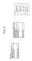
- Fig. 2 shows the content of map data stored in the map data storage unit 6.
- the map data includes management data, map basic data representing a map, and resource data.
- the production date and time etc. of the map data is described in the management data.
- the map basic data includes region data and region management data.
- the region data is provided for every region. For example, correspondence between the geographical range of each region and the region data and correspondence between each region and the region number, which is an identifier of the region, are described in the region management data.
- Each region data includes a 2D map unit, a 3D map unit, a text unit, and an icon unit.
- the 2D map unit indicates a two-dimensional map within the corresponding region.
- the 3D map unit indicates a three-dimensional map within the corresponding region.
- the text unit indicates a text representing, for example, a place name or a route name located on the two-dimensional or three-dimensional map within the corresponding region.
- the icon unit indicates an icon located on the two-dimensional or three-dimensional map within the corresponding region.
- the icon represents the position and type of a point of interest (POI) which is selected in advance and in which a user will be interested.
- a graphic representing the type of a point indicated by each icon is used as the icon.
- the resource data in the map data includes an information resource, such as color data or graphic data, of each region.
- the information resource is commonly used when a map is drawn in accordance with the region data.
- the navigation processor 13 uses outputs from the vehicle-state sensor group 3 and the GPS receiver 4, acquired through the I/O manager 11, and the map basic data in the map data, read out from the map data storage unit 6, to repeatedly calculate a most probable coordinate as the current position and a most probable direction as the current traveling direction by, for example, map matching to determine the calculated coordinate and direction to be the current position and the current traveling direction, respectively.
- the navigation processor 13 receives the specified destination and calculates a route having a minimum cost from the calculated current position to the destination as a recommended route on the basis of a predetermined cost model, such as a minimum distance model, by using the map basic data read out from the map data storage unit 6.
- the navigation processor 13 stores the calculated recommended route, in addition to the specified destination.
- the navigation processor 13 uses the 2D graphic engine 141 or the 3D graphic engine 142 in the window system 14 to display a guide image in the display apparatus 2.
- the navigation apparatus 1 has two display modes including a two-dimensional map display mode and a three-dimensional map display mode, which can be selectively set by the user.
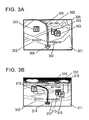
- the navigation processor 13 uses the 2D graphic engine 141 to display, on a 2D map image 301 representing a two-dimensional map, a guide image 300 including texts 302 representing a plane name etc. on the two-dimensional map, icons 303 representing the POIs, described above, on the two-dimensional map, a current position graphic 304 representing the current position calculated on the two-dimensional map, and so on, as shown in Fig. 3A.
- a recommended route graphic 305 representing part of the held recommended route toward the destination with respect to the current position on the two-dimensional map is further shown in the guide image 300 on the 2D map image 301. If a destination is held within the map display range, a destination graphic (not shown) representing the held destination on the two-dimensional map is further shown in the guide image 300 on the 2D map image 301.
- the map display range which is a geographical range on the two-dimensional map represented by the 2D map image 301, is defined in accordance with a reference position, a display direction, and a display scale as a geographical range around the reference position, having a predetermined size determined by using the determined display direction and the determined display scale.
- the navigation processor 13 normally sets the current position as the reference position, the calculated current traveling direction as the display direction, and a scale determined in accordance with user settings and initial settings set in advance as the display scale.
- the navigation processor 13 sets a position determined by the user operation as the current position, a direction selected by the user as the display direction, and a scale determined in accordance with the user settings and initial settings set in advance as the display scale.
- the navigation processor 13 uses the 3D graphic engine 142 to display, on a 3D map image 311 representing a three-dimensional map, a guide image 310 including texts 312 representing a plane name etc. on the three-dimensional map, icons 313 representing the POIs, described above, on the three-dimensional map, a current position graphic 314 representing the current position calculated on the three-dimensional map, and so on, as shown in Fig. 3B.
- a recommended route graphic 315 representing part of the held recommended route toward the destination with respect to the current position on the three-dimensional map is further shown in the guide image 310 on the 3D map image 311. If a destination is held within the map display range, a destination graphic (not shown) representing the held destination on the three-dimensional map is further shown in the guide image 310 on the 3D map image 311.
- the map display range which is a geographical range on the three-dimensional map represented by the 3D map image 311, is defined as a range yielded when the ground is observed from a point-of-view position set over the ground in a set line-of-sight direction at a set angle of view.
- the navigation processor 13 normally sets, as the point-of-view position, a position a distance corresponding to the above-described display scale above a position that is apart from the calculated current position in a direction opposite to the calculated current traveling direction by a distance corresponding to the above-described display scale.
- the navigation processor 13 normally sets, as the line-of-sight direction, a direction with respect to the point-of-view position toward a position that is apart from the calculated current position in the calculated current traveling direction by a distance corresponding to the above-described display scale.
- the navigation processor 13 normally sets, as the angle of view, an angle defined in advance by two directions orthogonal to the line-of-sight direction.
- the two directions orthogonal to the line-of-sight direction mean a direction orthogonal to a plane including three positions: the current position, the point-of-view position, and a position that is apart from the current position in the calculated current traveling direction by an arbitrary distance, and a direction orthogonal to the line-of-sight direction in the plane.
- the navigation processor 13 sets the point-of-view position, the line-of-sight direction, and the angle of view in accordance with the user operation.
- the navigation processor 13 writes display lists (DLs) in the VRAM 15 and issues system calls to request drawing of the written DLs to the 2D graphic engine 141 or the 3D graphic engine 142 to display the guide image 300 or the guide image 310 in the display apparatus 2.
- DLs display lists
- the navigation processor 13 writes text drawing DLs, icon drawing DLs, guide graphic drawing DLs, and 2D map image drawing DLs in the VRAM 15 when the two-dimensional map display mode is set.
- the texts 302 provided in the guide image 300 in Fig. 3A are described in the text drawing DLs.
- the icons 303 provided in the guide image 300 in Fig. 3A are described in the icon drawing DLs.
- the current position graphic 304, the recommended route graphic 305, and the destination graphic provided in the guide image 300 in Fig. 3A are described in the guide graphic drawing DLs.
- a two-dimensional region map of each region, at least part of which is included within the map display range of the 2D map image 301 drawn in the guide image 300 in Fig. 3A, is described in the 2D map image drawing DL.
- the navigation processor 13 writes text drawing DLs, icon drawing DLs, guide graphic drawing DLs, and 3D map image drawing DLs in the VRAM 15 when the three-dimensional map display mode is set.
- the texts 312 provided in the guide image 310 in Fig. 3B are described in the text drawing DLs.
- the icons 313 provided in the guide image 310 in Fig. 3B are described in the icon drawing DLs.
- the current position graphic 314, the recommended route graphic 315, and the destination graphic provided in the guide image 310 in Fig. 3B are described in the guide graphic drawing DLs.
- a three-dimensional region map of each region, at least part of which is included within the map display range of the 3D map image 311 drawn in the guide image 310 in Fig. 3B, is described in the 3D map image drawing DL.
- the navigation processor 13 generates the text drawing DLs in each display mode, the icon drawing DLs in each display mode, the 2D map image drawing DLs, and the 3D map image drawing DLs for every region, and writes the generated DLs in the VRAM 15.
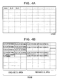
- Figs. 4A and 4B show the storage space in the VRAM 15. As shown in Fig. 4A, the storage space in the VRAM 15 is divided into multiple blocks each having a predetermined space, and a block number BL # is allocated to each block.
- the storage space in the VRAM 15 is grouped into a one-use DL area including multiple blocks and a reusable DL area including multiple blocks.
- the text drawing DLs, the icon drawing DLs, and the guide graphic drawing DLs are written in the one-use DL area by the navigation processor 13.
- the 2D map image drawing DLs and the 3D map image drawing DLs are written in the reusable DL area by the navigation processor 13.
- the writing of the DLs is controlled by the VRAM manager 16.
- the VRAM manager 16 allocates an area including empty blocks corresponding to the data capacity of the requested DL as the area of the DL and writes the requested DL in the allocated area. If the requested DL is any of the text drawing DL, the icon drawing DL, or the guide graphic drawing DL, the VRAM manager 16 allocates an area including empty blocks in the one-use DL area, corresponding to the data capacity of the requested DL, as the area of the DL. If the requested DL is the 2D map image drawing DL or the 3D map image drawing DL, the VRAM manager 16 allocates an area including empty blocks in the reusable DL area, corresponding to the data capacity of the requested DL, as the area of the DL.
- the multiple empty blocks allocated to the area of one DL may be multiple noncontinuous blocks in the VRAM 15.
- the empty blocks mean blocks that are not allocated to the area of any DL.
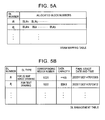
- the VRAM manager 16 holds a VRAM mapping table, shown in Fig. 5A, to manage the area of each DL.
- the VRAM mapping table includes entries for every DL stored in the VRAM 15.
- a DL number which is an identifier of the DL
- allocated block numbers which indicate the numbers of blocks allocated to the areas of the DL, are described in each entry.
- the navigation processor 13 holds a DL management table, shown in Fig. 5B, to manage the DLs written in the VRAM 15.
- the DL management table includes entries for every DL that has been written in the VRAM 15 and has not been deleted from the VRAM 15 by the navigation processor 13.
- a DL number, a DL type, a corresponding region number, a data capacity, and a final usage date and time are described in each entry.
- the DL number is the identifier of the DL.
- the DL type indicates a type of the DL, which is the text drawing DL, the icon drawing DL, the guide graphic drawing DL, the 2D map image drawing DL, or the 3D map image drawing DL.
- the corresponding region number indicates the number of a region corresponding to the DL.
- the data capacity indicates the number of bytes of the DL.
- the final usage date and time indicates a date and time when the DL was finally used.
- the region number is described only when the DL is not the guide graphic drawing DL.
- the date and time when the DL was finally used, described in the final usage date and time, is a date and time when the system call to request drawing of the DL was finally issued.
- the 2D map image drawing DL includes drawing attribute data and displayed 2D map drawing commands.
- the drawing attribute data includes data indicating whether drawing is necessary outside the display range, which is set to "YES" or "NO".
- a system call to request drawing of the 2D map image drawing DLs includes an instruction to draw the 2D map image drawing DLs, which is an operation code requesting drawing of the 2D map image drawing DLs.
- the system call also includes a drawing DL number list, which indicates the numbers of the 2D map image drawing DLs to be drawn, a drawing image display range, a scale, an angle of rotation, and an offset coordinate list, which are operands.
- the navigation processor 13 When regions A, B, C, and D are provided and a map display range 701 is calculated, as shown by a in Fig. 7, the navigation processor 13 reads out the 2D map units in the region data concerning the regions B and D, at least part of which is included within the map display range 701, from the map data storage unit 6. The navigation processor 13 then generates a DL-B, which is the 2D map image drawing DL of the region B, and a DL-D, which the 2D map image drawing DL of the region D, and writes the generated DL-B and DL-D in the VRAM 15.
- a DL-B which is the 2D map image drawing DL of the region B
- a DL-D which the 2D map image drawing DL of the region D
- the data indicating whether drawing is necessary outside the display range in the drawing attribute data in the 2D map image drawing DL-B for the region B is set to "NO".
- the displayed 2D map drawing commands in the DL-B includes drawing commands which request drawing of graphic elements in the two-dimensional map of the region B, shown by b in Fig. 7, and which the 2D graphic engine 141 can interpret.
- the two-dimensional map is defined by the 2D map unit in the region data concerning the region B and display settings set by the user.
- the displayed 2D map drawing commands in the DL-D includes drawing commands which request drawing of graphic elements in the two-dimensional map of the region D, shown by c in Fig. 7, and which the 2D graphic engine 141 can interpret.
- the two-dimensional map is defined by the 2D map unit in the region data concerning the region D and display settings set by the user.
- the display settings set by the user, defining the two-dimensional map to be displayed include the settings of colors and patterns of the graphic elements in the two-dimensional map to be displayed.
- the two-dimensional map of the region B, defined by the displayed 2D map drawing commands in the DL-B, and the two-dimensional map of the region D, defined by the displayed 2D map drawing commands in the DL-D, are drawn in coordinate spaces MX-MY set for every DL.
- the displayed 2D map drawing commands in the DL-B and the displayed 2D map drawing commands in the DL-D are set so that the two-dimensional map of the region B, defined by the displayed 2D map drawing commands in the DL-B, and the two-dimensional map of the region D, defined by the displayed 2D map drawing commands in the DL-D, have the same scale and are two-dimensionally arranged in the same direction.
- the navigation processor 13 After the DL-B and the DL-D are stored in the VRAM 15, the navigation processor 13 generates the system call to request drawing of the 2D map image drawing DLs, shown in Fig. 6B, and issues the generated system call to the 2D graphic engine 141.
- the drawing DL number list which is an operand of the system call, includes the DL numbers of the DL-B and the DL-D.
- the coordinate conversion matrix is used to arrange the two-dimensional map of the region B, defined in the DL-B shown by b in Fig. 7, and the two-dimensional map of region D, defined in the DL-D shown by c in Fig. 7, on a drawing coordinate space DX-DY in accordance with the positional relationship between the regions B and D in the above-described direction on the above-described scale, as shown by d in Fig. 7.
- the DL-B and the DL-D have the same scale and are two-dimensionally arranged in the same direction in this example, the DL-B and the DL-D have the same amount of expansion and amount of rotation and differs only in the amount of shift.
- a list of the different amounts of shift is described in the offset coordinate list.
- the range 711 is generated by arranging the two-dimensional map of the region B and the two-dimensional map of the region D, in the manner shown by d in Fig. 7.
- the range 711 described in the drawing image display range is set so that the geographical range corresponding to the two-dimensional map drawn in the range 711 coincides with the map display range 701.
- the 2D graphic engine 141 After receiving the system call described above, the 2D graphic engine 141 performs coordinate conversion to graphics which the 2D graphic engine 141 is requested to draw with the drawing commands included in the displayed 2D map drawing commands in the DL-B and the DL-D specified in the drawing DL number list, on the drawing coordinate space DX-DY in accordance with the scale, the angle of rotation, and the offset coordinate list, which are the operands in the system call, and draws the converted graphics in order to generate the map image shown by d in Fig. 7.
- the 2D map image within the range 711 described in the drawing image display range being the operand in the system call, within the drawn image is used as the 2D map image 301 shown in Fig. 3A.
- the range 711 described in the drawing image display range is set by the navigation processor 13 so that the geographical range corresponding to the two-dimensional map drawn in the range 711 coincides with the map display range 701.
- the 2D graphic engine 141 does not draw any graphic in accordance with the drawing commands outside the range 711 on the drawing coordinate space DX-DY. As a result, the drawing processing load on the 2D graphic engine 141 can be reduced.
- the 2D map image 301 shown in Fig. 3A is drawn by using the 2D map image drawing DLs by the process described above.
- the 3D map image drawing DL includes drawing attribute data and displayed 3D map data.
- the drawing attribute data includes data indicating whether drawing is necessary outside the display range, which is set to "YES” or “NO”, and data indicating whether it is necessary to draw an object in front of the current position, which is set to "YES” or "NO".
- a system call to request drawing of the 3D map image drawing DLs includes an instruction to draw a 3D map image drawing DLs, which is an operation code requesting drawing of the 3D map image drawing DLs.
- the system call also includes a drawing DL number list, which indicates the numbers of the 3D map image drawing DLs to be drawn, a point-of-view position, an angle of view, a line-of-sight direction, an offset coordinate list, and a coordinate corresponding to the current position, which are operands.
- the navigation processor 13 When regions A, B, C, and D are provided and a map display range 801 is calculated, as shown by a in Fig. 8, the navigation processor 13 reads out the 3D map units in the region data concerning the regions B and D, at least part of which is included within the map display range 801, from the map data storage unit 6. The navigation processor 13 then generates a DL-B, which is the 3D map image drawing DL of the region B, and a DL-D, which the 3D map image drawing DL of the region D, and writes the generated DL-B and DL-D in the VRAM 15.
- a DL-B which is the 3D map image drawing DL of the region B
- a DL-D which the 3D map image drawing DL of the region D
- the displayed 3D map data in the DL-B includes data concerning a three-dimensional model representing a three-dimensional map of the region B, shown by b in Fig. 8.
- the three-dimensional map is defined by the 3D map unit in the region data concerning the region B and display settings set by the user.
- the data concerning the three-dimensional model is not in the format of the 3D map unit but in a format which the 3D graphic engine 142 can interpret.
- both the data indicating whether drawing is necessary outside the display range and the data indicating whether it is necessary to draw an object in front of the current position, in the drawing attribute data in the 3D map image drawing DL-D for the region D are set to "NO".
- the displayed 3D map data in the DL-D includes data concerning a three-dimensional model representing a three-dimensional map of the region D, shown by c in Fig. 8.
- the three-dimensional map is defined by the 3D map unit in the region data concerning the region D and display settings set by the user.
- the display settings set by the user, defining the three-dimensional map to be displayed include the settings of colors and patterns of the elements in the three-dimensional map to be displayed and the settings of types of three-dimensional objects to be displayed (for example, the three-dimensional object representing a building four or less stories in height is not displayed).
- the three-dimensional map represented by the three-dimensional model of the region B, defined by the displayed 3D map data in the DL-B, and the three-dimensional map represented by the three-dimensional model of the region D, defined by the displayed 3D map data in the DL-D, are drawn in coordinate spaces MX-MY-MZ set for every DL.
- the displayed 3D map data in the DL-B and the displayed 3D map data in the DL-D are set so that the three-dimensional map represented by the three-dimensional model of the region B, defined by the displayed 3D map data in the DL-B, and the three-dimensional map represented by the three-dimensional model of the region D, defined by the displayed 3D map data in the DL-D, have the same scale and are arranged in the same MX direction and in the same MY direction.
- the navigation processor 13 After the DL-B and the DL-D are stored in the VRAM 15, the navigation processor 13 generates the system call to request drawing of the 3D map image drawing DLs, shown in Fig. 6D, and issues the generated system call to the 3D graphic engine 142.
- the drawing DL number list which is an operand of the system call, includes the DL numbers of the DL-B and the DL-D.
- An amount of shift is described in the offset coordinate list, which is an operand in the system call.
- the amount of shift is used to arrange the three-dimensional model representing the three-dimensional map of the region B, defined by the DL-B and shown by b in Fig. 8, and the three-dimensional model representing the three-dimensional map of the region D, defined by the DL-D and shown by c in Fig. 8, on a drawing coordinate space TX-TY-TZ in accordance with the positional relationship between the regions B and D, as shown by d in Fig. 8.
- the point-of-view position, the angle of view, and the line-of-sight direction on the drawing coordinate space TX-TY-TZ are described in the point-of-view position, the angle of view, and the line-of-sight direction, which are operands in the system call.
- the point-of-view position, the angle of view, and the line-of-sight direction are set so that the relationship between the point-of-view position, the line-of-sight direction, and the geographical range, described above, is satisfied between the three-dimensional maps of the regions B and D, represented by the three-dimensional models arranged as shown by d in Fig. 8.
- the position on the drawing coordinate space TX-TY-TZ, corresponding to the calculated current position, (the coordinate corresponding to the current position on the three-dimensional map represented by the three-dimensional model arranged as shown in by d Fig. 8) is described in the coordinate corresponding to the current position, which is an operand in the system call.
- the 3D graphic engine 142 After receiving the system call described above, the 3D graphic engine 142 arranges the three-dimensional models, represented by the displayed 3D map data concerning the DL-B and the DL-D indicated in the drawing DL number list, on the drawing coordinate space TX-TY-TZ in accordance with the offset coordinate list, which is an operand in the system call, in the manner shown by d in Fig. 8.
- the 3D graphic engine 142 uses the point-of-view position, the angle of view, and the line-of-sight direction, which are operands in the system call, to draw (render) a two-dimensional image yielded when the three-dimensional map of the regions B and D, represented by the three-dimensional model arranged in the manner shown by d in Fig.
- the 3D graphic engine 142 does not draw various objects, such as three-dimensional objects, which are defined by the point-of-view position, the line-of-sight direction, and the angle of view, which are drawn in the 3D map image 311, and which are arranged outside a range 812 in the drawing coordinate space TX-TY-TZ. As a result, the drawing processing load on 3D graphic engine 142 can be reduced.
- the 3D graphic engine 142 does not draw three-dimensional objects in front of the coordinate corresponding to the current position, which is an operand in the system call, viewed from the point-of-view position 811. As a result, it is possible to ensure good visibility of the current position graphic 314 displayed in the guide image 310 when the 3D map image 311 is drawn in the manner described above.
- the 3D map image 311 shown in Fig. 3B is drawn by using the DD map image drawing DLs by the process described above.
- the navigation processor 13 performs a process of drawing a 2D guide image to display the guide image 300 shown in Fig. 3A when the two-dimensional map display mode is set, and performs a process of drawing a 3D guide image to display the guide image 310 shown in Fig. 3B when the three-dimensional map display mode is set.
- the process of drawing the 2D map image 301 shown in Fig. 3A by using the 2D map image drawing DLs, described with reference to Figs. 6A, 6B, and 7, is performed by the navigation processor 13 and the 2D graphic engine 141 during the process of drawing a 2D guide image.
- the process of drawing the 3D map image 311 shown in Fig. 3B by using the 3D map image drawing DLs, described with reference to Figs. 6C, 6D, and 8, is performed by the navigation processor 13 and the 3D graphic engine 142 during the process of drawing a 3D guide image.
- Fig. 9 is a flowchart showing an example of the process of drawing a 2D guide image.
- Step S902 the process sets a timer used for determining a time interval (refresh rate) at which the display of the guide image 300 is updated.
- Step S904 the process calculates regions, at least part of which is included within the map display range set in the manner described above.
- Step S906 the process requests the VRAM manager 16 to delete all of the text drawing DLs, the icon drawing DLs, and the guide graphic drawing DLs in the one-use DL area in the VRAM 15.
- the VRAM manager 16 deletes all of the text drawing DLs, the icon drawing DLs, and the guide graphic drawing DLs in the one-use DL area, deletes the entries for the deleted DLs in the VRAM mapping table, and releases the blocks allocated to the DL areas of the deleted DLs.
- the navigation processor 13 deletes the entries for the deleted DLs in the DL management table.
- Step S908 the navigation processor 13 generates the guide graphic drawing DLs used for drawing the current position graphic 304, the recommended route graphic 305, and the destination graphic to be included in the guide image 300 on the basis of the current position, the current traveling direction, the recommended route, the destination, the map display range, the direction in which the map is displayed, and the scale on which the map is displayed, and requests the VRAM manager 16 to write the generated guide graphic drawing DLs in the VRAM 15.
- the navigation processor 13 refers to the DL management table to set the regions, the 2D map image drawing DLs for which have been already stored in the VRAM 15, among the regions calculated in Step S904, as reuse regions. It is determined that the 2D map image drawing DL for a region is stored in the VRAM 15 if the DL management table has any entry in which the region number of the region is registered as the corresponding region number and the 2D map image drawing DL is registered as the DL type.
- Step S912 the navigation processor 13 generates the text drawing DL used for drawing the text 302 to be included in the guide image on the basis of the text unit in the region data concerning each reuse region, the map display range, the direction in which the map is displayed, and the scale on which the map is displayed, and requests the VRAM manager 16 to write the generated text drawing DL in the VRAM 15.
- Step S914 the navigation processor 13 generates the icon drawing DL used for drawing the icon 303 to be included in the guide image on the basis of the icon unit in the region data concerning each reuse region, the map display range, the direction in which the map is displayed, and the scale on which the map is displayed, and requests the VRAM manager 16 to write the generated icon drawing DL in the VRAM 15.
- the VRAM manager 16 allocates the DL area for the requested DL in the one-use DL area and writes the DL in the allocated DL area.
- the VRAM manager 16 generates the entry for the written DL in the VRAM mapping table, and registers the DL number of the written DL and the numbers of the blocks allocated to the DL area of the written DL in the generated entry.
- the navigation processor 13 generates the entry for the written DL in the DL management table, and registers the DL number and DL type of the written DL, the region number of the region corresponding to the written DL, and the data capacity of the written guide graphic drawing DL in the generated entry as the DL number, the DL type, the corresponding region number, and the data capacity, respectively.
- Step S916 the navigation processor 13 sets the regions other than the regions set as the reuse regions, among the regions calculated in Step S904, as normal drawing regions.
- the navigation processor 13 performs the following steps for the normal drawing regions through Steps S918, S928, and S940.
- Step S920 the navigation processor 13 generates the text drawing DL used for drawing the texts 302 to be included in the guide image on the basis of the text unit in the region data concerning the region, the map display range, the direction in which the map is displayed, and the scale on which the map is displayed, and requests the VRAM manager 16 to write the generated text drawing DL in the VRAM 15.
- Step S922 the navigation processor 13 generates the icon drawing DL used for drawing the icons 303 to be included in the guide image on the basis of the icon unit in the region data concerning the region, the map display range, the direction in which the map is displayed, and the scale on which the map is displayed, and requests the VRAM manager 16 to write the generated icon drawing DL in the VRAM 15.
- Step S924 the navigation processor 13 generates the 2D map image drawing DL for the region in the manner described above and requests the VRAM manager 16 to write the generated 2D map image drawing DL in the VRAM 15.
- the VRAM manager 16 allocates the DL area for the requested DL in the reusable DL area.
- the VRAM manager 16 writes the DL in the allocated DL area, if the DL area can be allocated, and generates the entry for the written DL in the VRAM mapping table.
- the VRAM manager 16 registers the DL number of the written DL and the numbers of the blocks allocated to the DL area of the written DL in the generated entry and indicates to the navigation processor 13 that the writing succeeds.
- the navigation processor 13 In response to the indication that the writing succeeds, the navigation processor 13 generates the entry for the written DL in the DL management table, and registers the DL number and DL type of the written DL, the region number of the region corresponding to the written DL, and the data capacity of the written guide graphic drawing DL in the generated entry as the DL number, the DL type, the corresponding region number, and the data capacity, respectively. If the VRAM manager 16 cannot allocate the DL area for the requested DL in the reusable DL area due to insufficient empty blocks, the VRAM manager 16 indicates to the navigation processor 13 that the reusable DL area is short of empty areas.
- Step S926 the navigation processor 13 determines whether the writing succeeds. If the navigation processor 13 determines that the writing succeeds, the navigation processor 13 terminates the process for the normal drawing region.
- Step S926 If the navigation processor 13 determines in Step S926 that the writing fails, that is, if the VRAM manager 16 indicates to the navigation processor 13 that the reusable DL area is short of empty areas in response to the request for writing of the 2D map image drawing DL, then in Step S938, the navigation processor 13 requests the VRAM manager 16 to delete the DL indicated by the DL number of the entry having the oldest final usage date and time, among the entries having the 2D map image drawing DL as the DL type in the DL management table, and goes back to Step S924.
- the navigation processor 13 may request the VRAM manager 16 to delete the DL indicated by the DL number of the entry having the oldest final usage date and time, among the entries having the 2D map image drawing DL as the DL type in the DL management table and having the data capacity greater than the data capacity of the DL that has issued the request for writing.
- the VRAM manager 16 deletes the 2D map image drawing DL, the deletion of which from the reusable DL area in the VRAM 15 is requested.
- the VRAM manager 16 deletes the entry for the deleted DL from the VRAM mapping table and releases the blocks allocated to the DL area for the DL to provide empty blocks.
- the navigation processor 13 deletes the entry for the deleted 2D map image drawing DL from the DL management table.
- Step S930 the navigation processor 13 generates the system call to request drawing of the 2D map image drawing DL for each region, calculated in Step S904, in the manner described above and issues the generated system call to the 2D graphic engine 141.
- the 2D map image drawing DL for each region calculated in Step S904 is calculated as the DL having the DL number described in the entry in which the 2D map image drawing DL is registered as the DL type in the DL management table and in which the region number of each region calculated in Step S904 is registered as the corresponding region number in the DL management table.
- Step S932 the navigation processor 13 generates the system call to request drawing of the text drawing DL and the system call to request drawing of the icon drawing DL for each region, calculated in Step S904, and issues the generated system calls to the 2D graphic engine 141.
- Step S934 the navigation processor 13 generates the system call to request drawing of the guide graphic drawing DL written in the VRAM 15 in Step S908 and issues the generated system call to the 2D graphic engine 141.
- navigation processor 13 When navigation processor 13 has requested drawing of the DLs with the system calls, the navigation processor 13 registers the current date and time as the final usage date and time in the entries in the DL management table, in which the DL numbers of the requested DLs are registered.
- Step S902 After issuing the system calls to request drawing of the DLs to the 2D graphic engine 141, the navigation processor 13 waits for timeout and goes back to Step S902 to repeat the above steps.
- the 2D guide image is drawn by the process described above.
- the navigation processor 13 uses the 2D map image drawing DL that has been written in the VRAM 15 to draw the 2D map image 301.
- the load for the generation of the 2D map image drawing DL on the navigation processor 13 can be reduced.
- the navigation processor 13 In the process of drawing a 2D guide image, the navigation processor 13 generates the DL-B, which is the 2D map image drawing DL for the region B and which represents the two-dimensional map shown by b in Fig. 7, and the DL-D, which is the 2D map image drawing DL for the region D and which represents the two-dimensional map shown by c in Fig. 7, on the basis of the map display range 701 set across regions B and D, as shown by a in Fig. 7, writes the generated DL-B and DL-D in the VRAM 15, and issues the system calls.
- the navigation processor 13, then, generates an image of the range 711 shown by d in Fig. 7, corresponding to the map display range 701 shown by a in Fig.
- the navigation processor 13 If a map display range 1001 including part of the region A and part of the region B is set, as shown by a in Fig. 10, after the above steps, the navigation processor 13 generates the 2D map image 301 representing the two-dimensional map of the map display range 1001 in a manner described below.
- the navigation processor 13 generates a DL-A, which is the 2D map image drawing DL for the region A and which represents the three-dimensional map shown by b in Fig. 10, among the regions A and B part of which is included within the map display range 1001, and writes the generated DL-A in the VRAM 15.
- the navigation processor 13 generates only the DL-A because the 2D map image drawing DL for the region A is not held in the VRAM 15.
- the navigation processor 13 issues the system calls to request drawing of the written DL-A and the DL-B, which has been held in the VRAM 15, which represents the two-dimensional map shown by c in Fig.
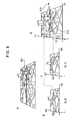
- the process of drawing a 3D guide image is similar to the process of drawing a 2D guide image shown in Fig. 9, except that the 3D map image drawing DLs are processed instead of the 2D map image drawing DLs.
- the system calls are issued to the 3D graphic engine 142, instead of the 2D graphic engine 141.
- the 3D map image drawing DL that has been written in the VRAM 15 can be used for drawing the 3D map image 311 including the guide image 310 to be displayed, the 3D map image drawing DL that has been written in the VRAM 15 is used to draw the 3D map image 311.
- the load for the generation of the 3D map image drawing DL on the navigation processor 13 can be reduced.
- the navigation processor 13 In the process of drawing a 3D guide image, the navigation processor 13 generates the DL-B, which is the 3D map image drawing DL for the region B and which represents the three-dimensional map shown by b in Fig. 8, and the DL-D, which is the 3D map image drawing DL for the region D and which represents the three-dimensional map shown by c in Fig. 8, on the basis of the map display range 801 set across the regions B and D, as shown by a in Fig. 8, writes the generated DL-B and DL-D in the VRAM 15, and issues the system calls.
- the DL-B which is the 3D map image drawing DL for the region B and which represents the three-dimensional map shown by b in Fig. 8
- the DL-D which is the 3D map image drawing DL for the region D and which represents the three-dimensional map shown by c in Fig. 8
- the navigation processor 13 then, generates an image of the range 812 that is yielded when the three-dimensional maps of the regions B and D are observed from the point-of-view position 811 shown by d in Fig. 8 in the line-of-sight direction at the angle of view and that corresponds to the map display range 801 shown by a in Fig. 8 as the 3D map image 311 and displays the guide image 310 on the generated 3D map image 311.
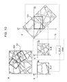
- a map display range 1101 is set so as to include part of the region A and part of the region B, as shown by a in Fig. 11, after the above steps, the navigation processor 13 generates the 2D map image 301 representing the three-dimensional map of the map display range 1101 in a manner described below.
- the navigation processor 13 generates a DL-A, which is the 3D map image drawing DL for the region A and which represents the three-dimensional map shown by b in Fig. 11, among the regions A and B part of which is included within the map display range 1101, and writes the generated DL-A in the VRAM 15.
- the navigation processor 13 generates only the DL-A because the 3D map image drawing DL for the region A is not held in the VRAM 15.
- the navigation processor 13 issues the system calls to request drawing of the written DL-A and the DL-B, which has been held in the VRAM 15, which represents the three-dimensional map shown by c in Fig.
Landscapes
- Engineering & Computer Science (AREA)
- Radar, Positioning & Navigation (AREA)
- Remote Sensing (AREA)
- Physics & Mathematics (AREA)
- General Physics & Mathematics (AREA)
- Automation & Control Theory (AREA)
- Instructional Devices (AREA)
- Processing Or Creating Images (AREA)
- Navigation (AREA)
- Traffic Control Systems (AREA)
Abstract
Description
- The present invention relates to a technology of displaying a map in a navigation apparatus that performs location guide by using the map.
- Technologies of displaying a map in a navigation apparatus include technologies of displaying an image of a three-dimensional map (for example, refer to
Japanese Unexamined Patent Application Publication No. 2004-219182 - It is preferred that a higher-quality map be displayed in a navigation apparatus.
- However, the amount of processing to display a map on the basis of map data in the navigation apparatus, particularly, to display an image of a three-dimensional map is relatively great. Accordingly, displaying a fine map at a higher resolution or increasing the frequency of update of the displayed map in order to improve the quality can result in a heavier processing load on the navigation apparatus to display the map.
- Accordingly, it is an object of the present invention to reduce the processing load for display of a map in a navigation apparatus.
- According to an embodiment of the present invention, a navigation apparatus includes map data storing means for storing map data including region map data that is provided for every region and that defines a map of the region; image drawing means for drawing an image; region map-image data storing means for storing region map-image data that is generated for every region and that defines an image representing the map of the region for the image drawing means; and region map-image data generating means for, if the region map-image data concerning each region, at least part of which is included in a map display range being a geographical range in which the map is displayed, is not stored in the region map-image data storing means, generating the region map-image data concerning the region on the basis of the region map data concerning the region, included in the map data stored in the map data storing means, and storing the generated region map-image data in the region map-image data storing means. The image drawing means uses the region map-image data for every region, at least part of which is included within the map display range, the region map-image data being stored in the region map-image data storing means, to draw the image of the map of the map display range as the image of the map to be displayed.
- The region map-image data may include a drawing command to request drawing of each graphic element in the map of the region. In this case, the image drawing means performs coordinate conversion to the graphic elements represented by the drawing command included in the region map-image data concerning each region, at least part of which is included within the map display range, the region map-image data being stored in the region map-image data storing means, so that the graphic elements are included in the map of the map display range, and draws the converted graphic elements to draw the image of the map of the map display range as the image of the map to be displayed.
- The region map data may define a three-dimensional map in the region and the region map-image data may include three-dimensional data concerning each graphic element in the three-dimensional map of the region. In this case, the image drawing means renders, with respect to a predetermined point of view, an area corresponding to the map display range in a virtual three-dimensional world being a collection of the three-dimensional data included in the region map-image data concerning the region, at least part of which is included within the map display range, the region map-image data being stored in the region map-image data storing means, to draw the image of the three-dimensional map of the map display range as the image of the map to be displayed.
- The navigation apparatus having the above configuration uses the region map-image data that has been stored in the region map-image data storing means to draw the map to be displayed and does not generate the region map-image data concerning the region for which the stored region map-image data can be used, if the region map-image data that has been stored in the region map-image data storing means concerns the region, at least part of which is included in the map to be displayed. Accordingly, it is possible to reduce the processing load for the generation of the region map-image data and the storage of the region map-image data in the region map-image data storing means.
- When the region map data defines the three-dimensional map in the region, the navigation apparatus may further include current-position calculating means for calculating a current position and current-position displaying means for displaying a current position mark representing the current position at a position on the displayed map, corresponding to the calculated current position. The image drawing means does not need to render a three-dimensional object in front of the position corresponding to the current position in the virtual three-dimensional world with respect to the point of view used in the rendering, among three-dimensional objects represented by the three-dimensional data.
- In this case, the region map-image data that has been stored in the region map-image data storing means is used and the three-dimensional object in front of the current position in the virtual three-dimensional world with respect to the point of view used in the rendering is not rendered, so that a user can easily recognize the current position mark.
- If the region map-image data storing means does not have the empty space sufficient to store the generated region map-image data, the region map-image data generating means may delete the region map-image data selected according to predetermined criteria from the region map-image data storing means. In this case, appropriately setting the predetermined criteria to use the limited storage space of the region map-image data storing means allows the processing load for the generation of the region map-image data and the storage of the region map-image data in the region map-image data storing means to be reduced.
- It is preferred that the image drawing means does not draw the image of the map on the basis of the region map-image data concerning each region, at least part of which is included within the map display range, the region map-image data being stored in the region map-image data storing means, outside the map display range.
- In this case, the processing load for the drawing of the map on the image drawing means can be reduced.
- According to the present invention, it is possible to reduce the processing load for display of a map on the navigation apparatus.
-
- Fig. 1 is a block diagram showing an example of the configuration of a navigation system according to an embodiment of the present invention;
- Fig. 2 shows the content of map data stored in the navigation system according to the embodiment of the present invention;
- Figs. 3A and 3B show examples of screens displayed in the navigation system according to the embodiment of the present invention;
- Figs. 4A and 4B show the structure of a VRAM in the navigation system according to the embodiment of the present invention;
- Figs. 5A and 5B show a VRAM mapping table and a DL management table, respectively, in the navigation system according to the embodiment of the present invention;
- Figs. 6A to 6D show display lists and system calls used for displaying guide images in the navigation system according to the embodiment of the present invention;
- Fig. 7 shows an example illustrating how to generate a two-dimensional map image in the navigation system according to the embodiment of the present invention;
- Fig. 8 shows an example illustrating how to generate a three-dimensional map image in the navigation system according to the embodiment of the present invention;
- Fig. 9 is a flowchart showing a process of drawing a 2D guide image in the navigation system according to the embodiment of the present invention;
- Fig. 10 shows another example illustrating how to generate the two-dimensional map image in the navigation system according to the embodiment of the present invention; and
- Fig. 11 shows another example illustrating how to generate the three-dimensional map image in the navigation system according to the embodiment of the present invention.
- Embodiments of the present invention will now be described with reference to the attached drawings.
- Fig. 1 is a block diagram showing an example of the configuration of a navigation system according to an embodiment of the present invention. The navigation system according to the embodiment of the present invention is mounted in a car.
- Referring to Fig. 1, the navigation system includes a
navigation apparatus 1, a display apparatus 2, a vehicle-state sensor group 3, a global positioning system (GPS)receiver 4, anoperation unit 5, and a mapdata storage unit 6, which is a storage device, such as a digital versatile disk (DVD) drive or a hard disk drive (HDD), storing map data representing a map. The vehicle-state sensor group 3 includes a directional sensor, such as an angular acceleration sensor or a geomagnetic sensor, and a vehicle speed sensor, such as a vehicle speed pulse sensor. The vehicle-state sensor group 3 detects a state of the vehicle. - The
navigation apparatus 1 includes an input-output (I/O) manager 11, adisplay apparatus driver 12, anavigation processor 13, awindow system 14, a video random access memory (VRAM) 15, and aVRAM manager 16. The I/O manager 11 controls input and output between thenavigation apparatus 1 and the vehicle-state sensor group 3, theGPS receiver 4, theoperation unit 5, and the mapdata storage unit 6. Thedisplay apparatus driver 12 controls display in the display apparatus 2. Thewindow system 14 displays a map in the display apparatus 2 via thedisplay apparatus driver 12 in response to a request from thenavigation processor 13. - The
window system 14 includes a two-dimensional (2D)graphic engine 141 and a three-dimensional (3D)graphic engine 142. The 2Dgraphic engine 141 provides thenavigation processor 13 with a function of drawing and displaying a 2D graphic. The 3Dgraphic engine 142 provides thenavigation processor 13 with a function of drawing and displaying a 3D graphic. TheVRAM 15 includes data concerning graphics which thenavigation apparatus 1 uses the 2Dgraphic engine 141 and the 3Dgraphic engine 142 to draw. TheVRAM manager 16 manages and controls theVRAM 15. - The
navigation apparatus 1 described above may be an electronic computer which is hardware having a common structure and which includes a microprocessor, a memory, and peripheral devices including a graphic processor. In this case, the components in thenavigation apparatus 1 may be realized as processes embodied by the microprocessor that executes programs prepared in advance. The programs may be supplied to thenavigation apparatus 1 through a storage medium or an appropriate communication path. The 2Dgraphic engine 141 and the 3Dgraphic engine 142 may use the functions of the graphic processor to draw 2D graphics and 3D graphics, respectively. - Fig. 2 shows the content of map data stored in the map
data storage unit 6. - As shown in Fig. 2, the map data includes management data, map basic data representing a map, and resource data. The production date and time etc. of the map data is described in the management data.
- The map basic data includes region data and region management data. The region data is provided for every region. For example, correspondence between the geographical range of each region and the region data and correspondence between each region and the region number, which is an identifier of the region, are described in the region management data.
- Each region data includes a 2D map unit, a 3D map unit, a text unit, and an icon unit. The 2D map unit indicates a two-dimensional map within the corresponding region. The 3D map unit indicates a three-dimensional map within the corresponding region. The text unit indicates a text representing, for example, a place name or a route name located on the two-dimensional or three-dimensional map within the corresponding region. The icon unit indicates an icon located on the two-dimensional or three-dimensional map within the corresponding region. The icon represents the position and type of a point of interest (POI) which is selected in advance and in which a user will be interested. A graphic representing the type of a point indicated by each icon is used as the icon.
- The resource data in the map data includes an information resource, such as color data or graphic data, of each region. The information resource is commonly used when a map is drawn in accordance with the region data.
- In the configuration described above, the
navigation processor 13 uses outputs from the vehicle-state sensor group 3 and theGPS receiver 4, acquired through the I/O manager 11, and the map basic data in the map data, read out from the mapdata storage unit 6, to repeatedly calculate a most probable coordinate as the current position and a most probable direction as the current traveling direction by, for example, map matching to determine the calculated coordinate and direction to be the current position and the current traveling direction, respectively. In addition, when a destination is specified by a user with theoperation unit 5 and is supplied to thenavigation processor 13 via the I/O manager 11, thenavigation processor 13 receives the specified destination and calculates a route having a minimum cost from the calculated current position to the destination as a recommended route on the basis of a predetermined cost model, such as a minimum distance model, by using the map basic data read out from the mapdata storage unit 6. Thenavigation processor 13 stores the calculated recommended route, in addition to the specified destination. - The
navigation processor 13 uses the 2Dgraphic engine 141 or the 3Dgraphic engine 142 in thewindow system 14 to display a guide image in the display apparatus 2. - The
navigation apparatus 1 has two display modes including a two-dimensional map display mode and a three-dimensional map display mode, which can be selectively set by the user. - When the two-dimensional map display mode is set, the
navigation processor 13 uses the 2Dgraphic engine 141 to display, on a2D map image 301 representing a two-dimensional map, aguide image 300 includingtexts 302 representing a plane name etc. on the two-dimensional map,icons 303 representing the POIs, described above, on the two-dimensional map, a current position graphic 304 representing the current position calculated on the two-dimensional map, and so on, as shown in Fig. 3A. If a recommended route is held within a map display range, which is a geographical range on the two-dimensional map represented by the2D map image 301, a recommended route graphic 305 representing part of the held recommended route toward the destination with respect to the current position on the two-dimensional map is further shown in theguide image 300 on the2D map image 301. If a destination is held within the map display range, a destination graphic (not shown) representing the held destination on the two-dimensional map is further shown in theguide image 300 on the2D map image 301. - The map display range, which is a geographical range on the two-dimensional map represented by the
2D map image 301, is defined in accordance with a reference position, a display direction, and a display scale as a geographical range around the reference position, having a predetermined size determined by using the determined display direction and the determined display scale. Thenavigation processor 13 normally sets the current position as the reference position, the calculated current traveling direction as the display direction, and a scale determined in accordance with user settings and initial settings set in advance as the display scale. During scrolling in response to a map scrolling operation by the user, thenavigation processor 13 sets a position determined by the user operation as the current position, a direction selected by the user as the display direction, and a scale determined in accordance with the user settings and initial settings set in advance as the display scale. - When the three-dimensional map display mode is set, the
navigation processor 13 uses the 3Dgraphic engine 142 to display, on a3D map image 311 representing a three-dimensional map, aguide image 310 includingtexts 312 representing a plane name etc. on the three-dimensional map,icons 313 representing the POIs, described above, on the three-dimensional map, a current position graphic 314 representing the current position calculated on the three-dimensional map, and so on, as shown in Fig. 3B. If a recommended route is held within a map display range, which is a geographical range on the three-dimensional map represented by the3D map image 311, a recommended route graphic 315 representing part of the held recommended route toward the destination with respect to the current position on the three-dimensional map is further shown in theguide image 310 on the3D map image 311. If a destination is held within the map display range, a destination graphic (not shown) representing the held destination on the three-dimensional map is further shown in theguide image 310 on the3D map image 311. - The map display range, which is a geographical range on the three-dimensional map represented by the
3D map image 311, is defined as a range yielded when the ground is observed from a point-of-view position set over the ground in a set line-of-sight direction at a set angle of view. Thenavigation processor 13 normally sets, as the point-of-view position, a position a distance corresponding to the above-described display scale above a position that is apart from the calculated current position in a direction opposite to the calculated current traveling direction by a distance corresponding to the above-described display scale. Thenavigation processor 13 normally sets, as the line-of-sight direction, a direction with respect to the point-of-view position toward a position that is apart from the calculated current position in the calculated current traveling direction by a distance corresponding to the above-described display scale. Thenavigation processor 13 normally sets, as the angle of view, an angle defined in advance by two directions orthogonal to the line-of-sight direction. The two directions orthogonal to the line-of-sight direction mean a direction orthogonal to a plane including three positions: the current position, the point-of-view position, and a position that is apart from the current position in the calculated current traveling direction by an arbitrary distance, and a direction orthogonal to the line-of-sight direction in the plane. During scrolling in response to a map scrolling operation by the user, thenavigation processor 13 sets the point-of-view position, the line-of-sight direction, and the angle of view in accordance with the user operation. - The
navigation processor 13 writes display lists (DLs) in theVRAM 15 and issues system calls to request drawing of the written DLs to the 2Dgraphic engine 141 or the 3Dgraphic engine 142 to display theguide image 300 or theguide image 310 in the display apparatus 2. - The
navigation processor 13 writes text drawing DLs, icon drawing DLs, guide graphic drawing DLs, and 2D map image drawing DLs in theVRAM 15 when the two-dimensional map display mode is set. Thetexts 302 provided in theguide image 300 in Fig. 3A are described in the text drawing DLs. Theicons 303 provided in theguide image 300 in Fig. 3A are described in the icon drawing DLs. The current position graphic 304, the recommended route graphic 305, and the destination graphic provided in theguide image 300 in Fig. 3A are described in the guide graphic drawing DLs. A two-dimensional region map of each region, at least part of which is included within the map display range of the2D map image 301 drawn in theguide image 300 in Fig. 3A, is described in the 2D map image drawing DL. - The
navigation processor 13 writes text drawing DLs, icon drawing DLs, guide graphic drawing DLs, and 3D map image drawing DLs in theVRAM 15 when the three-dimensional map display mode is set. Thetexts 312 provided in theguide image 310 in Fig. 3B are described in the text drawing DLs. Theicons 313 provided in theguide image 310 in Fig. 3B are described in the icon drawing DLs. The current position graphic 314, the recommended route graphic 315, and the destination graphic provided in theguide image 310 in Fig. 3B are described in the guide graphic drawing DLs. A three-dimensional region map of each region, at least part of which is included within the map display range of the3D map image 311 drawn in theguide image 310 in Fig. 3B, is described in the 3D map image drawing DL. - The
navigation processor 13 generates the text drawing DLs in each display mode, the icon drawing DLs in each display mode, the 2D map image drawing DLs, and the 3D map image drawing DLs for every region, and writes the generated DLs in theVRAM 15. - Figs. 4A and 4B show the storage space in the
VRAM 15. As shown in Fig. 4A, the storage space in theVRAM 15 is divided into multiple blocks each having a predetermined space, and a block number BL # is allocated to each block. - As shown in Fig. 4B, the storage space in the
VRAM 15 is grouped into a one-use DL area including multiple blocks and a reusable DL area including multiple blocks. The text drawing DLs, the icon drawing DLs, and the guide graphic drawing DLs are written in the one-use DL area by thenavigation processor 13. The 2D map image drawing DLs and the 3D map image drawing DLs are written in the reusable DL area by thenavigation processor 13. - The writing of the DLs is controlled by the
VRAM manager 16. - Specifically, when writing of a DL is requested by the
navigation processor 13, theVRAM manager 16 allocates an area including empty blocks corresponding to the data capacity of the requested DL as the area of the DL and writes the requested DL in the allocated area. If the requested DL is any of the text drawing DL, the icon drawing DL, or the guide graphic drawing DL, theVRAM manager 16 allocates an area including empty blocks in the one-use DL area, corresponding to the data capacity of the requested DL, as the area of the DL. If the requested DL is the 2D map image drawing DL or the 3D map image drawing DL, theVRAM manager 16 allocates an area including empty blocks in the reusable DL area, corresponding to the data capacity of the requested DL, as the area of the DL. The multiple empty blocks allocated to the area of one DL may be multiple noncontinuous blocks in theVRAM 15. The empty blocks mean blocks that are not allocated to the area of any DL. - The
VRAM manager 16 holds a VRAM mapping table, shown in Fig. 5A, to manage the area of each DL. - As shown in Fig. 5A, the VRAM mapping table includes entries for every DL stored in the
VRAM 15. A DL number, which is an identifier of the DL, and allocated block numbers, which indicate the numbers of blocks allocated to the areas of the DL, are described in each entry. - The
navigation processor 13 holds a DL management table, shown in Fig. 5B, to manage the DLs written in theVRAM 15. - As shown in Fig. 5B, the DL management table includes entries for every DL that has been written in the
VRAM 15 and has not been deleted from theVRAM 15 by thenavigation processor 13. A DL number, a DL type, a corresponding region number, a data capacity, and a final usage date and time are described in each entry. The DL number is the identifier of the DL. The DL type indicates a type of the DL, which is the text drawing DL, the icon drawing DL, the guide graphic drawing DL, the 2D map image drawing DL, or the 3D map image drawing DL. The corresponding region number indicates the number of a region corresponding to the DL. The data capacity indicates the number of bytes of the DL. The final usage date and time indicates a date and time when the DL was finally used. The region number is described only when the DL is not the guide graphic drawing DL. The date and time when the DL was finally used, described in the final usage date and time, is a date and time when the system call to request drawing of the DL was finally issued. - An outline of a process of drawing the
2D map image 301, shown in Fig. 3A, by using the 2D map image drawing DLs will now be described. - As shown in Fig. 6A, the 2D map image drawing DL includes drawing attribute data and displayed 2D map drawing commands. The drawing attribute data includes data indicating whether drawing is necessary outside the display range, which is set to "YES" or "NO".
- As shown in Fig. 6B, a system call to request drawing of the 2D map image drawing DLs includes an instruction to draw the 2D map image drawing DLs, which is an operation code requesting drawing of the 2D map image drawing DLs. The system call also includes a drawing DL number list, which indicates the numbers of the 2D map image drawing DLs to be drawn, a drawing image display range, a scale, an angle of rotation, and an offset coordinate list, which are operands.
- When regions A, B, C, and D are provided and a
map display range 701 is calculated, as shown by a in Fig. 7, thenavigation processor 13 reads out the 2D map units in the region data concerning the regions B and D, at least part of which is included within themap display range 701, from the mapdata storage unit 6. Thenavigation processor 13 then generates a DL-B, which is the 2D map image drawing DL of the region B, and a DL-D, which the 2D map image drawing DL of the region D, and writes the generated DL-B and DL-D in theVRAM 15. - The data indicating whether drawing is necessary outside the display range in the drawing attribute data in the 2D map image drawing DL-B for the region B is set to "NO". The displayed 2D map drawing commands in the DL-B includes drawing commands which request drawing of graphic elements in the two-dimensional map of the region B, shown by b in Fig. 7, and which the 2D
graphic engine 141 can interpret. The two-dimensional map is defined by the 2D map unit in the region data concerning the region B and display settings set by the user. - Similarly, the data indicating whether drawing is necessary outside the display range in the drawing attribute data in the 2D map image drawing DL-D for the region D is set to "NO". The displayed 2D map drawing commands in the DL-D includes drawing commands which request drawing of graphic elements in the two-dimensional map of the region D, shown by c in Fig. 7, and which the 2D
graphic engine 141 can interpret. The two-dimensional map is defined by the 2D map unit in the region data concerning the region D and display settings set by the user. - The display settings set by the user, defining the two-dimensional map to be displayed, include the settings of colors and patterns of the graphic elements in the two-dimensional map to be displayed.
- The two-dimensional map of the region B, defined by the displayed 2D map drawing commands in the DL-B, and the two-dimensional map of the region D, defined by the displayed 2D map drawing commands in the DL-D, are drawn in coordinate spaces MX-MY set for every DL. The displayed 2D map drawing commands in the DL-B and the displayed 2D map drawing commands in the DL-D are set so that the two-dimensional map of the region B, defined by the displayed 2D map drawing commands in the DL-B, and the two-dimensional map of the region D, defined by the displayed 2D map drawing commands in the DL-D, have the same scale and are two-dimensionally arranged in the same direction.
- After the DL-B and the DL-D are stored in the
VRAM 15, thenavigation processor 13 generates the system call to request drawing of the 2D map image drawing DLs, shown in Fig. 6B, and issues the generated system call to the 2Dgraphic engine 141. The drawing DL number list, which is an operand of the system call, includes the DL numbers of the DL-B and the DL-D. - An amount of expansion, an amount of rotation, and an amount of shift determining a coordinate conversion matrix are described in the scale, the angle of rotation, and the offset coordinate list, respectively, which are operands of the system call. The coordinate conversion matrix is used to arrange the two-dimensional map of the region B, defined in the DL-B shown by b in Fig. 7, and the two-dimensional map of region D, defined in the DL-D shown by c in Fig. 7, on a drawing coordinate space DX-DY in accordance with the positional relationship between the regions B and D in the above-described direction on the above-described scale, as shown by d in Fig. 7. Since the two-dimensional map of the region B, defined by the displayed 2D map drawing commands in the DL-B, and the two-dimensional map of the region D, defined by the displayed 2D map drawing commands in the DL-D, have the same scale and are two-dimensionally arranged in the same direction in this example, the DL-B and the DL-D have the same amount of expansion and amount of rotation and differs only in the amount of shift. A list of the different amounts of shift is described in the offset coordinate list.
- A
range 711 to be displayed in the display apparatus 2, within the image drawn in the drawing coordinate space DX-DY, is described in the drawing image display range in the system call. Therange 711 is generated by arranging the two-dimensional map of the region B and the two-dimensional map of the region D, in the manner shown by d in Fig. 7. Therange 711 described in the drawing image display range is set so that the geographical range corresponding to the two-dimensional map drawn in therange 711 coincides with themap display range 701. - After receiving the system call described above, the 2D
graphic engine 141 performs coordinate conversion to graphics which the 2Dgraphic engine 141 is requested to draw with the drawing commands included in the displayed 2D map drawing commands in the DL-B and the DL-D specified in the drawing DL number list, on the drawing coordinate space DX-DY in accordance with the scale, the angle of rotation, and the offset coordinate list, which are the operands in the system call, and draws the converted graphics in order to generate the map image shown by d in Fig. 7. The 2D map image within therange 711 described in the drawing image display range being the operand in the system call, within the drawn image, is used as the2D map image 301 shown in Fig. 3A. As described above, therange 711 described in the drawing image display range is set by thenavigation processor 13 so that the geographical range corresponding to the two-dimensional map drawn in therange 711 coincides with themap display range 701. - If the data indicating whether drawing is necessary outside the display range in the drawing attribute data in the 2D map image drawing DL is set to "NO", the 2D
graphic engine 141 does not draw any graphic in accordance with the drawing commands outside therange 711 on the drawing coordinate space DX-DY. As a result, the drawing processing load on the 2Dgraphic engine 141 can be reduced. - The
2D map image 301 shown in Fig. 3A is drawn by using the 2D map image drawing DLs by the process described above. - An outline of a process of drawing the
3D map image 311, shown in Fig. 3B, by using the 3D map image drawing DLs will now be described. - As shown in Fig. 6C, the 3D map image drawing DL includes drawing attribute data and displayed 3D map data. The drawing attribute data includes data indicating whether drawing is necessary outside the display range, which is set to "YES" or "NO", and data indicating whether it is necessary to draw an object in front of the current position, which is set to "YES" or "NO".
- As shown in Fig. 6D, a system call to request drawing of the 3D map image drawing DLs includes an instruction to draw a 3D map image drawing DLs, which is an operation code requesting drawing of the 3D map image drawing DLs. The system call also includes a drawing DL number list, which indicates the numbers of the 3D map image drawing DLs to be drawn, a point-of-view position, an angle of view, a line-of-sight direction, an offset coordinate list, and a coordinate corresponding to the current position, which are operands.
- When regions A, B, C, and D are provided and a
map display range 801 is calculated, as shown by a in Fig. 8, thenavigation processor 13 reads out the 3D map units in the region data concerning the regions B and D, at least part of which is included within themap display range 801, from the mapdata storage unit 6. Thenavigation processor 13 then generates a DL-B, which is the 3D map image drawing DL of the region B, and a DL-D, which the 3D map image drawing DL of the region D, and writes the generated DL-B and DL-D in theVRAM 15. - Both the data indicating whether drawing is necessary outside the display range and the data indicating whether it is necessary to draw an object in front of the current position, in the drawing attribute data in the 3D map image drawing DL-B for the region B, are set to "NO". The displayed 3D map data in the DL-B includes data concerning a three-dimensional model representing a three-dimensional map of the region B, shown by b in Fig. 8. The three-dimensional map is defined by the 3D map unit in the region data concerning the region B and display settings set by the user. The data concerning the three-dimensional model is not in the format of the 3D map unit but in a format which the 3D
graphic engine 142 can interpret. - Similarly, both the data indicating whether drawing is necessary outside the display range and the data indicating whether it is necessary to draw an object in front of the current position, in the drawing attribute data in the 3D map image drawing DL-D for the region D, are set to "NO". The displayed 3D map data in the DL-D includes data concerning a three-dimensional model representing a three-dimensional map of the region D, shown by c in Fig. 8. The three-dimensional map is defined by the 3D map unit in the region data concerning the region D and display settings set by the user.
- The display settings set by the user, defining the three-dimensional map to be displayed, include the settings of colors and patterns of the elements in the three-dimensional map to be displayed and the settings of types of three-dimensional objects to be displayed (for example, the three-dimensional object representing a building four or less stories in height is not displayed).
- The three-dimensional map represented by the three-dimensional model of the region B, defined by the displayed 3D map data in the DL-B, and the three-dimensional map represented by the three-dimensional model of the region D, defined by the displayed 3D map data in the DL-D, are drawn in coordinate spaces MX-MY-MZ set for every DL. The displayed 3D map data in the DL-B and the displayed 3D map data in the DL-D are set so that the three-dimensional map represented by the three-dimensional model of the region B, defined by the displayed 3D map data in the DL-B, and the three-dimensional map represented by the three-dimensional model of the region D, defined by the displayed 3D map data in the DL-D, have the same scale and are arranged in the same MX direction and in the same MY direction.
- After the DL-B and the DL-D are stored in the
VRAM 15, thenavigation processor 13 generates the system call to request drawing of the 3D map image drawing DLs, shown in Fig. 6D, and issues the generated system call to the 3Dgraphic engine 142. The drawing DL number list, which is an operand of the system call, includes the DL numbers of the DL-B and the DL-D. - An amount of shift is described in the offset coordinate list, which is an operand in the system call. The amount of shift is used to arrange the three-dimensional model representing the three-dimensional map of the region B, defined by the DL-B and shown by b in Fig. 8, and the three-dimensional model representing the three-dimensional map of the region D, defined by the DL-D and shown by c in Fig. 8, on a drawing coordinate space TX-TY-TZ in accordance with the positional relationship between the regions B and D, as shown by d in Fig. 8.
- The point-of-view position, the angle of view, and the line-of-sight direction on the drawing coordinate space TX-TY-TZ are described in the point-of-view position, the angle of view, and the line-of-sight direction, which are operands in the system call. The point-of-view position, the angle of view, and the line-of-sight direction are set so that the relationship between the point-of-view position, the line-of-sight direction, and the geographical range, described above, is satisfied between the three-dimensional maps of the regions B and D, represented by the three-dimensional models arranged as shown by d in Fig. 8.
- The position on the drawing coordinate space TX-TY-TZ, corresponding to the calculated current position, (the coordinate corresponding to the current position on the three-dimensional map represented by the three-dimensional model arranged as shown in by d Fig. 8) is described in the coordinate corresponding to the current position, which is an operand in the system call.
- After receiving the system call described above, the 3D
graphic engine 142 arranges the three-dimensional models, represented by the displayed 3D map data concerning the DL-B and the DL-D indicated in the drawing DL number list, on the drawing coordinate space TX-TY-TZ in accordance with the offset coordinate list, which is an operand in the system call, in the manner shown by d in Fig. 8. The 3Dgraphic engine 142 uses the point-of-view position, the angle of view, and the line-of-sight direction, which are operands in the system call, to draw (render) a two-dimensional image yielded when the three-dimensional map of the regions B and D, represented by the three-dimensional model arranged in the manner shown by d in Fig. 8, is observed from a point-of-view position 811 in the line-of-sight direction at the angle of view and arranges a sky image simulating the sky over the drawn two-dimensional image in order to draw the3D map image 311 shown in Fig. 3B. - If the data indicating whether drawing is necessary outside the display range in the drawing attribute data in the 3D map image drawing DL is set to "NO", the 3D
graphic engine 142 does not draw various objects, such as three-dimensional objects, which are defined by the point-of-view position, the line-of-sight direction, and the angle of view, which are drawn in the3D map image 311, and which are arranged outside arange 812 in the drawing coordinate space TX-TY-TZ. As a result, the drawing processing load on 3Dgraphic engine 142 can be reduced. If the data indicating whether it is necessary to draw an object in front of the current position is set to "NO", the 3Dgraphic engine 142 does not draw three-dimensional objects in front of the coordinate corresponding to the current position, which is an operand in the system call, viewed from the point-of-view position 811. As a result, it is possible to ensure good visibility of the current position graphic 314 displayed in theguide image 310 when the3D map image 311 is drawn in the manner described above. - The
3D map image 311 shown in Fig. 3B is drawn by using the DD map image drawing DLs by the process described above. - The
navigation processor 13 performs a process of drawing a 2D guide image to display theguide image 300 shown in Fig. 3A when the two-dimensional map display mode is set, and performs a process of drawing a 3D guide image to display theguide image 310 shown in Fig. 3B when the three-dimensional map display mode is set. - The process of drawing the
2D map image 301 shown in Fig. 3A by using the 2D map image drawing DLs, described with reference to Figs. 6A, 6B, and 7, is performed by thenavigation processor 13 and the 2Dgraphic engine 141 during the process of drawing a 2D guide image. The process of drawing the3D map image 311 shown in Fig. 3B by using the 3D map image drawing DLs, described with reference to Figs. 6C, 6D, and 8, is performed by thenavigation processor 13 and the 3Dgraphic engine 142 during the process of drawing a 3D guide image. - The process of drawing a 2D guide image to display the
guide image 300 shown in Fig. 3A will now be described. - Fig. 9 is a flowchart showing an example of the process of drawing a 2D guide image.
- Referring to Fig. 9, in Step S902, the process sets a timer used for determining a time interval (refresh rate) at which the display of the
guide image 300 is updated. In Step S904, the process calculates regions, at least part of which is included within the map display range set in the manner described above. - In Step S906, the process requests the
VRAM manager 16 to delete all of the text drawing DLs, the icon drawing DLs, and the guide graphic drawing DLs in the one-use DL area in theVRAM 15. TheVRAM manager 16 deletes all of the text drawing DLs, the icon drawing DLs, and the guide graphic drawing DLs in the one-use DL area, deletes the entries for the deleted DLs in the VRAM mapping table, and releases the blocks allocated to the DL areas of the deleted DLs. Thenavigation processor 13 deletes the entries for the deleted DLs in the DL management table. - In Step S908, the
navigation processor 13 generates the guide graphic drawing DLs used for drawing the current position graphic 304, the recommended route graphic 305, and the destination graphic to be included in theguide image 300 on the basis of the current position, the current traveling direction, the recommended route, the destination, the map display range, the direction in which the map is displayed, and the scale on which the map is displayed, and requests theVRAM manager 16 to write the generated guide graphic drawing DLs in theVRAM 15. - In Step S910, the
navigation processor 13 refers to the DL management table to set the regions, the 2D map image drawing DLs for which have been already stored in theVRAM 15, among the regions calculated in Step S904, as reuse regions. It is determined that the 2D map image drawing DL for a region is stored in theVRAM 15 if the DL management table has any entry in which the region number of the region is registered as the corresponding region number and the 2D map image drawing DL is registered as the DL type. - In Step S912, the
navigation processor 13 generates the text drawing DL used for drawing thetext 302 to be included in the guide image on the basis of the text unit in the region data concerning each reuse region, the map display range, the direction in which the map is displayed, and the scale on which the map is displayed, and requests theVRAM manager 16 to write the generated text drawing DL in theVRAM 15. In Step S914, thenavigation processor 13 generates the icon drawing DL used for drawing theicon 303 to be included in the guide image on the basis of the icon unit in the region data concerning each reuse region, the map display range, the direction in which the map is displayed, and the scale on which the map is displayed, and requests theVRAM manager 16 to write the generated icon drawing DL in theVRAM 15. - In response to the request for writing of the guide graphic drawing DL, the text drawing DL, or the icon drawing DL, the
VRAM manager 16 allocates the DL area for the requested DL in the one-use DL area and writes the DL in the allocated DL area. TheVRAM manager 16 generates the entry for the written DL in the VRAM mapping table, and registers the DL number of the written DL and the numbers of the blocks allocated to the DL area of the written DL in the generated entry. Thenavigation processor 13 generates the entry for the written DL in the DL management table, and registers the DL number and DL type of the written DL, the region number of the region corresponding to the written DL, and the data capacity of the written guide graphic drawing DL in the generated entry as the DL number, the DL type, the corresponding region number, and the data capacity, respectively. - In Step S916, the
navigation processor 13 sets the regions other than the regions set as the reuse regions, among the regions calculated in Step S904, as normal drawing regions. - The
navigation processor 13 performs the following steps for the normal drawing regions through Steps S918, S928, and S940. - In Step S920, the
navigation processor 13 generates the text drawing DL used for drawing thetexts 302 to be included in the guide image on the basis of the text unit in the region data concerning the region, the map display range, the direction in which the map is displayed, and the scale on which the map is displayed, and requests theVRAM manager 16 to write the generated text drawing DL in theVRAM 15. In Step S922, thenavigation processor 13 generates the icon drawing DL used for drawing theicons 303 to be included in the guide image on the basis of the icon unit in the region data concerning the region, the map display range, the direction in which the map is displayed, and the scale on which the map is displayed, and requests theVRAM manager 16 to write the generated icon drawing DL in theVRAM 15. - In Step S924, the
navigation processor 13 generates the 2D map image drawing DL for the region in the manner described above and requests theVRAM manager 16 to write the generated 2D map image drawing DL in theVRAM 15. - In response to the request for the writing of the 2D map image drawing DL, the
VRAM manager 16 allocates the DL area for the requested DL in the reusable DL area. TheVRAM manager 16 writes the DL in the allocated DL area, if the DL area can be allocated, and generates the entry for the written DL in the VRAM mapping table. TheVRAM manager 16 registers the DL number of the written DL and the numbers of the blocks allocated to the DL area of the written DL in the generated entry and indicates to thenavigation processor 13 that the writing succeeds. In response to the indication that the writing succeeds, thenavigation processor 13 generates the entry for the written DL in the DL management table, and registers the DL number and DL type of the written DL, the region number of the region corresponding to the written DL, and the data capacity of the written guide graphic drawing DL in the generated entry as the DL number, the DL type, the corresponding region number, and the data capacity, respectively. If theVRAM manager 16 cannot allocate the DL area for the requested DL in the reusable DL area due to insufficient empty blocks, theVRAM manager 16 indicates to thenavigation processor 13 that the reusable DL area is short of empty areas. - In Step S926, the
navigation processor 13 determines whether the writing succeeds. If thenavigation processor 13 determines that the writing succeeds, thenavigation processor 13 terminates the process for the normal drawing region. - If the
navigation processor 13 determines in Step S926 that the writing fails, that is, if theVRAM manager 16 indicates to thenavigation processor 13 that the reusable DL area is short of empty areas in response to the request for writing of the 2D map image drawing DL, then in Step S938, thenavigation processor 13 requests theVRAM manager 16 to delete the DL indicated by the DL number of the entry having the oldest final usage date and time, among the entries having the 2D map image drawing DL as the DL type in the DL management table, and goes back to Step S924. Thenavigation processor 13 may request theVRAM manager 16 to delete the DL indicated by the DL number of the entry having the oldest final usage date and time, among the entries having the 2D map image drawing DL as the DL type in the DL management table and having the data capacity greater than the data capacity of the DL that has issued the request for writing. - In response to the request for deletion of the 2D map image drawing DL, the
VRAM manager 16 deletes the 2D map image drawing DL, the deletion of which from the reusable DL area in theVRAM 15 is requested. TheVRAM manager 16 deletes the entry for the deleted DL from the VRAM mapping table and releases the blocks allocated to the DL area for the DL to provide empty blocks. Thenavigation processor 13 deletes the entry for the deleted 2D map image drawing DL from the DL management table. - If Steps S924, S926, and S938 for all the normal drawing regions have been finished, then in Step S930, the
navigation processor 13 generates the system call to request drawing of the 2D map image drawing DL for each region, calculated in Step S904, in the manner described above and issues the generated system call to the 2Dgraphic engine 141. The 2D map image drawing DL for each region calculated in Step S904 is calculated as the DL having the DL number described in the entry in which the 2D map image drawing DL is registered as the DL type in the DL management table and in which the region number of each region calculated in Step S904 is registered as the corresponding region number in the DL management table. - In Step S932, the
navigation processor 13 generates the system call to request drawing of the text drawing DL and the system call to request drawing of the icon drawing DL for each region, calculated in Step S904, and issues the generated system calls to the 2Dgraphic engine 141. In Step S934, thenavigation processor 13 generates the system call to request drawing of the guide graphic drawing DL written in theVRAM 15 in Step S908 and issues the generated system call to the 2Dgraphic engine 141. - When
navigation processor 13 has requested drawing of the DLs with the system calls, thenavigation processor 13 registers the current date and time as the final usage date and time in the entries in the DL management table, in which the DL numbers of the requested DLs are registered. - After issuing the system calls to request drawing of the DLs to the 2D
graphic engine 141, thenavigation processor 13 waits for timeout and goes back to Step S902 to repeat the above steps. - The 2D guide image is drawn by the process described above.
- As described above, in the process of drawing a 2D guide image, when the 2D map image drawing DL that has been written in the
VRAM 15 can be used for drawing of the2D map image 301 including theguide image 300 to be displayed, thenavigation processor 13 uses the 2D map image drawing DL that has been written in theVRAM 15 to draw the2D map image 301. As a result, the load for the generation of the 2D map image drawing DL on thenavigation processor 13 can be reduced. - For example, in the process of drawing a 2D guide image, the
navigation processor 13 generates the DL-B, which is the 2D map image drawing DL for the region B and which represents the two-dimensional map shown by b in Fig. 7, and the DL-D, which is the 2D map image drawing DL for the region D and which represents the two-dimensional map shown by c in Fig. 7, on the basis of themap display range 701 set across regions B and D, as shown by a in Fig. 7, writes the generated DL-B and DL-D in theVRAM 15, and issues the system calls. Thenavigation processor 13, then, generates an image of therange 711 shown by d in Fig. 7, corresponding to themap display range 701 shown by a in Fig. 7, as the2D map image 301 and displays theguide image 300 on the generated2D map image 301. If amap display range 1001 including part of the region A and part of the region B is set, as shown by a in Fig. 10, after the above steps, thenavigation processor 13 generates the2D map image 301 representing the two-dimensional map of themap display range 1001 in a manner described below. - Specifically, the
navigation processor 13 generates a DL-A, which is the 2D map image drawing DL for the region A and which represents the three-dimensional map shown by b in Fig. 10, among the regions A and B part of which is included within themap display range 1001, and writes the generated DL-A in theVRAM 15. Thenavigation processor 13 generates only the DL-A because the 2D map image drawing DL for the region A is not held in theVRAM 15. Thenavigation processor 13 issues the system calls to request drawing of the written DL-A and the DL-B, which has been held in theVRAM 15, which represents the two-dimensional map shown by c in Fig. 10, and which is the 2D map image drawing DL for the region B, and causes the 2Dgraphic engine 141 to draw an image of arange 1011 shown by d in Fig. 10, corresponding to themap display range 1001 shown by a in Fig. 10, as the2D map image 301. As a result, it is not necessary to generate the 2D map image drawing DL for the region B and to write the generated 2D map image drawing DL in theVRAM 15, among the regions A and B part of which is included within themap display range 1001, in order to generate the2D map image 301. - The process of drawing a 3D guide image will now be described.
- The process of drawing a 3D guide image is similar to the process of drawing a 2D guide image shown in Fig. 9, except that the 3D map image drawing DLs are processed instead of the 2D map image drawing DLs. In the process of drawing a 3D guide image, the system calls are issued to the 3D
graphic engine 142, instead of the 2Dgraphic engine 141. - In the process of drawing a 3D guide image, as in the process of drawing a 2D guide image, if the 3D map image drawing DL that has been written in the
VRAM 15 can be used for drawing the3D map image 311 including theguide image 310 to be displayed, the 3D map image drawing DL that has been written in theVRAM 15 is used to draw the3D map image 311. As a result, the load for the generation of the 3D map image drawing DL on thenavigation processor 13 can be reduced. - For example, in the process of drawing a 3D guide image, the
navigation processor 13 generates the DL-B, which is the 3D map image drawing DL for the region B and which represents the three-dimensional map shown by b in Fig. 8, and the DL-D, which is the 3D map image drawing DL for the region D and which represents the three-dimensional map shown by c in Fig. 8, on the basis of themap display range 801 set across the regions B and D, as shown by a in Fig. 8, writes the generated DL-B and DL-D in theVRAM 15, and issues the system calls. Thenavigation processor 13, then, generates an image of therange 812 that is yielded when the three-dimensional maps of the regions B and D are observed from the point-of-view position 811 shown by d in Fig. 8 in the line-of-sight direction at the angle of view and that corresponds to themap display range 801 shown by a in Fig. 8 as the3D map image 311 and displays theguide image 310 on the generated3D map image 311. If amap display range 1101 is set so as to include part of the region A and part of the region B, as shown by a in Fig. 11, after the above steps, thenavigation processor 13 generates the2D map image 301 representing the three-dimensional map of themap display range 1101 in a manner described below. - Specifically, the
navigation processor 13 generates a DL-A, which is the 3D map image drawing DL for the region A and which represents the three-dimensional map shown by b in Fig. 11, among the regions A and B part of which is included within themap display range 1101, and writes the generated DL-A in theVRAM 15. Thenavigation processor 13 generates only the DL-A because the 3D map image drawing DL for the region A is not held in theVRAM 15. Thenavigation processor 13 issues the system calls to request drawing of the written DL-A and the DL-B, which has been held in theVRAM 15, which represents the three-dimensional map shown by c in Fig. 11, and which is the 3D map image drawing DL for the region B, and causes the 3Dgraphic engine 142 to draw an image of arange 1112 shown by d in Fig. 11, which is yielded when the three-dimensional maps of the regions A and B are observed from a point-of-view position 1111 shown by d in Fig. 11 in the line-of-sight direction at the angle of view and which corresponds to themap display range 1101 shown by a in Fig. 11, as the3D map image 311. As a result, it is not necessary to generate the 3D map image drawing DL for the region B and to write the 3D map image drawing DL in theVRAM 15, among the regions A and B part of which is included within themap display range 1101, in order to generate the3D map image 311.
Claims (6)
- A navigation apparatus comprising:map data storing means (6) for storing map data including region map data that are provided for every region available and that defines a map of the region;image drawing means (141, 142) for drawing an image;region map-image data storing means (15) for storing region map-image data that is generated for respective region and that defines an image representing the map of the region for the image drawing means; andregion map-image data generating means (13) for, if the region map-image data concerning each region, at least part of which is included in a map display range being a geographical range in which the map is displayed, is not stored in the region map-image data storing means, generating the region map-image data concerning the region on the basis of the region map data concerning the region, included in the map data stored in the map data storing means, and storing the generated region map-image data in the region map-image data storing means,wherein the image drawing means uses the region map-image data for every region, at least part of which is included within the map display range, the region map-image data being stored in the region map-image data storing means, to draw the image of the map of the map display range as the image of the map to be displayed.
- The navigation apparatus according to Claim 1,
wherein the region map-image data includes a drawing command to request drawing of each graphic element in the map of the region, and
wherein the image drawing means performs coordinate conversion to the graphic elements represented by the drawing command included in the region map-image data concerning each region, at least part of which is included within the map display range, the region map-image data being stored in the region map-image data storing means, so that the graphic elements are included in the map of the map display range, and draws the converted graphic elements to draw the image of the map of the map display range as the image of the map to be displayed. - The navigation apparatus according to Claim 1 or 2,
wherein the region map data defines a three-dimensional map in the region,
wherein the region map-image data includes three-dimensional data concerning each graphic element in the three-dimensional map of the region, and
wherein the image drawing means renders, with respect to a predetermined point of view, an area corresponding to the map display range in a virtual three-dimensional world being a collection of the three-dimensional data included in the region map-image data concerning the region, at least part of which is included within the map display range, the region map-image data being stored in the region map-image data storing means, to draw the image of the three-dimensional map of the map display range as the image of the map to be displayed. - The navigation apparatus according to Claim 3, further comprising:current-position calculating means for calculating a current position; andcurrent-position displaying means for displaying a current position mark representing the current position at a position on the displayed map, corresponding to the calculated current position,wherein the image drawing means does not render a three-dimensional object in front of the position corresponding to the current position in the virtual three-dimensional world with respect to the point of view used in the rendering, among three-dimensional objects represented by the three-dimensional data.
- The navigation apparatus according to Claim 1, 2, 3, or 4,
wherein, if the region map-image data storing means does not have the empty space sufficient to store the generated region map-image data, the region map-image data generating means deletes the region map-image data selected according to predetermined criteria from the region map-image data storing means. - The navigation apparatus according to Claim 1, 2, 3, 4, or 5,
wherein the image drawing means does not draw the image of the map on the basis of the region map-image data concerning each region, at least part of which is included within the map display range, the region map-image data being stored in the region map-image data storing means, outside the map display range.
Applications Claiming Priority (1)
| Application Number | Priority Date | Filing Date | Title |
|---|---|---|---|
| JP2005360139A JP4711818B2 (en) | 2005-12-14 | 2005-12-14 | Navigation device and map display method |
Publications (2)
| Publication Number | Publication Date |
|---|---|
| EP1798521A1 true EP1798521A1 (en) | 2007-06-20 |
| EP1798521B1 EP1798521B1 (en) | 2016-07-20 |
Family
ID=37814651
Family Applications (1)
| Application Number | Title | Priority Date | Filing Date |
|---|---|---|---|
| EP06025843.1A Expired - Fee Related EP1798521B1 (en) | 2005-12-14 | 2006-12-13 | Navigation apparatus |
Country Status (3)
| Country | Link |
|---|---|
| EP (1) | EP1798521B1 (en) |
| JP (1) | JP4711818B2 (en) |
| CN (1) | CN1982846B (en) |
Cited By (1)
| Publication number | Priority date | Publication date | Assignee | Title |
|---|---|---|---|---|
| TWI409443B (en) * | 2009-03-23 | 2013-09-21 | Htc Corp | Method and system for designating directions of points of interest and computer program product using the method |
Families Citing this family (5)
| Publication number | Priority date | Publication date | Assignee | Title |
|---|---|---|---|---|
| CN102192742B (en) * | 2010-03-09 | 2014-02-05 | 深圳市宇恒互动科技开发有限公司 | Navigation method and device |
| JP2013044611A (en) * | 2011-08-23 | 2013-03-04 | Navitime Japan Co Ltd | Route search device, route search method, computer program, route search system, server, and terminal device |
| US9058681B2 (en) * | 2012-06-01 | 2015-06-16 | The Boeing Company | Sensor-enhanced localization in virtual and physical environments |
| KR102332752B1 (en) * | 2014-11-24 | 2021-11-30 | 삼성전자주식회사 | Map service providing apparatus and method |
| JP6297482B2 (en) * | 2014-12-26 | 2018-03-20 | 日立オートモティブシステムズ株式会社 | Information processing device |
Citations (6)
| Publication number | Priority date | Publication date | Assignee | Title |
|---|---|---|---|---|
| EP0510939A2 (en) * | 1991-04-25 | 1992-10-28 | Pioneer Electronic Corporation | On-board navigation apparatus |
| EP1146316A2 (en) | 2000-04-14 | 2001-10-17 | Alpine Electronics, Inc. | Navigation system |
| US20020049532A1 (en) * | 2000-09-27 | 2002-04-25 | Hikaru Nakamura | Navigation system and method of displaying quasi-three-dimensional map information |
| EP1460604A2 (en) * | 1996-04-16 | 2004-09-22 | Xanavi Informatics Corporation | Map display device, navigation device and map display method |
| US20040183700A1 (en) * | 2003-01-06 | 2004-09-23 | Nobuhide Morie | Navigation device |
| EP1526359A1 (en) * | 2003-10-20 | 2005-04-27 | Lg Electronics Inc. | Method for managing map data for vehicle |
Family Cites Families (5)
| Publication number | Priority date | Publication date | Assignee | Title |
|---|---|---|---|---|
| JPH08166762A (en) * | 1994-12-14 | 1996-06-25 | Zanavy Informatics:Kk | Map display device for vehicle |
| JPH08211827A (en) * | 1995-02-08 | 1996-08-20 | Hitachi Ltd | Map plotting device |
| JP3550444B2 (en) * | 1995-06-12 | 2004-08-04 | 株式会社日立製作所 | Graphics display |
| JPH1115371A (en) * | 1997-06-25 | 1999-01-22 | Fujitsu Ten Ltd | Map displaying apparatus |
| CN2687613Y (en) * | 2002-08-09 | 2005-03-23 | 爱信艾达株式会社 | Map display device |
-
2005
- 2005-12-14 JP JP2005360139A patent/JP4711818B2/en active Active
-
2006
- 2006-12-13 EP EP06025843.1A patent/EP1798521B1/en not_active Expired - Fee Related
- 2006-12-14 CN CN2006101684935A patent/CN1982846B/en not_active Expired - Fee Related
Patent Citations (6)
| Publication number | Priority date | Publication date | Assignee | Title |
|---|---|---|---|---|
| EP0510939A2 (en) * | 1991-04-25 | 1992-10-28 | Pioneer Electronic Corporation | On-board navigation apparatus |
| EP1460604A2 (en) * | 1996-04-16 | 2004-09-22 | Xanavi Informatics Corporation | Map display device, navigation device and map display method |
| EP1146316A2 (en) | 2000-04-14 | 2001-10-17 | Alpine Electronics, Inc. | Navigation system |
| US20020049532A1 (en) * | 2000-09-27 | 2002-04-25 | Hikaru Nakamura | Navigation system and method of displaying quasi-three-dimensional map information |
| US20040183700A1 (en) * | 2003-01-06 | 2004-09-23 | Nobuhide Morie | Navigation device |
| EP1526359A1 (en) * | 2003-10-20 | 2005-04-27 | Lg Electronics Inc. | Method for managing map data for vehicle |
Cited By (1)
| Publication number | Priority date | Publication date | Assignee | Title |
|---|---|---|---|---|
| TWI409443B (en) * | 2009-03-23 | 2013-09-21 | Htc Corp | Method and system for designating directions of points of interest and computer program product using the method |
Also Published As
| Publication number | Publication date |
|---|---|
| JP2007163300A (en) | 2007-06-28 |
| EP1798521B1 (en) | 2016-07-20 |
| CN1982846A (en) | 2007-06-20 |
| JP4711818B2 (en) | 2011-06-29 |
| CN1982846B (en) | 2012-01-25 |
Similar Documents
| Publication | Publication Date | Title |
|---|---|---|
| JP3108122B2 (en) | Car navigation system | |
| JP4486175B2 (en) | 3D map display apparatus and method | |
| EP1435507B1 (en) | Hierarchical system and method for on-demand loading of data in a navigation system | |
| US6163749A (en) | Method and system for scrolling a map display in a navigation application | |
| JP3474053B2 (en) | Map display method for navigation device and navigation device | |
| US20140375638A1 (en) | Map display device | |
| US20070073475A1 (en) | Navigation apparatus and map display device | |
| JP5276780B2 (en) | Map display system | |
| EP1798521B1 (en) | Navigation apparatus | |
| JP2002098538A (en) | Navigation system and method for displaying information of pseudo three dimensional map | |
| JPWO2006092853A1 (en) | Map display device and map display method | |
| JP2003337041A (en) | Map display system, method for displaying map and program | |
| JPH04288584A (en) | Map display device | |
| JP2001174271A (en) | Navigation apparatus | |
| EP2192568A1 (en) | Map drawing device | |
| CN114166239A (en) | Navigation application with novel simple mode | |
| JP4491541B2 (en) | 3D map display device and navigation device | |
| JP3642776B2 (en) | Map display method of navigation device and navigation device | |
| JPH11161159A (en) | Three-dimensional map display device | |
| JP5007059B2 (en) | Stereoscopic in-vehicle display | |
| US9846819B2 (en) | Map image display device, navigation device, and map image display method | |
| JP2012127791A (en) | Navigation device and control method therefor and program | |
| JPH09134122A (en) | Vehicle use map display device | |
| JP2007121797A (en) | Map display device | |
| JP2007078774A (en) | Vehicle guiding device |
Legal Events
| Date | Code | Title | Description |
|---|---|---|---|
| PUAI | Public reference made under article 153(3) epc to a published international application that has entered the european phase |
Free format text: ORIGINAL CODE: 0009012 |
|
| AK | Designated contracting states |
Kind code of ref document: A1 Designated state(s): AT BE BG CH CY CZ DE DK EE ES FI FR GB GR HU IE IS IT LI LT LU LV MC NL PL PT RO SE SI SK TR |
|
| AX | Request for extension of the european patent |
Extension state: AL BA HR MK YU |
|
| 17P | Request for examination filed |
Effective date: 20071210 |
|
| AKX | Designation fees paid |
Designated state(s): DE FR GB |
|
| 17Q | First examination report despatched |
Effective date: 20090420 |
|
| GRAP | Despatch of communication of intention to grant a patent |
Free format text: ORIGINAL CODE: EPIDOSNIGR1 |
|
| RIC1 | Information provided on ipc code assigned before grant |
Ipc: G01C 21/32 20060101AFI20160317BHEP Ipc: G01C 21/36 20060101ALI20160317BHEP |
|
| INTG | Intention to grant announced |
Effective date: 20160405 |
|
| GRAS | Grant fee paid |
Free format text: ORIGINAL CODE: EPIDOSNIGR3 |
|
| GRAA | (expected) grant |
Free format text: ORIGINAL CODE: 0009210 |
|
| AK | Designated contracting states |
Kind code of ref document: B1 Designated state(s): DE FR GB |
|
| REG | Reference to a national code |
Ref country code: GB Ref legal event code: FG4D |
|
| REG | Reference to a national code |
Ref country code: DE Ref legal event code: R096 Ref document number: 602006049643 Country of ref document: DE |
|
| REG | Reference to a national code |
Ref country code: FR Ref legal event code: PLFP Year of fee payment: 11 |
|
| REG | Reference to a national code |
Ref country code: DE Ref legal event code: R097 Ref document number: 602006049643 Country of ref document: DE |
|
| PLBE | No opposition filed within time limit |
Free format text: ORIGINAL CODE: 0009261 |
|
| STAA | Information on the status of an ep patent application or granted ep patent |
Free format text: STATUS: NO OPPOSITION FILED WITHIN TIME LIMIT |
|
| 26N | No opposition filed |
Effective date: 20170421 |
|
| REG | Reference to a national code |
Ref country code: DE Ref legal event code: R082 Ref document number: 602006049643 Country of ref document: DE Representative=s name: SCHMITT-NILSON SCHRAUD WAIBEL WOHLFROM PATENTA, DE |
|
| REG | Reference to a national code |
Ref country code: FR Ref legal event code: PLFP Year of fee payment: 12 |
|
| PGFP | Annual fee paid to national office [announced via postgrant information from national office to epo] |
Ref country code: FR Payment date: 20201223 Year of fee payment: 15 Ref country code: DE Payment date: 20201211 Year of fee payment: 15 Ref country code: GB Payment date: 20201223 Year of fee payment: 15 |
|
| REG | Reference to a national code |
Ref country code: DE Ref legal event code: R119 Ref document number: 602006049643 Country of ref document: DE |
|
| GBPC | Gb: european patent ceased through non-payment of renewal fee |
Effective date: 20211213 |
|
| PG25 | Lapsed in a contracting state [announced via postgrant information from national office to epo] |
Ref country code: GB Free format text: LAPSE BECAUSE OF NON-PAYMENT OF DUE FEES Effective date: 20211213 Ref country code: DE Free format text: LAPSE BECAUSE OF NON-PAYMENT OF DUE FEES Effective date: 20220701 |
|
| PG25 | Lapsed in a contracting state [announced via postgrant information from national office to epo] |
Ref country code: FR Free format text: LAPSE BECAUSE OF NON-PAYMENT OF DUE FEES Effective date: 20211231 |