EP1788036A1 - Process for the preparation of J-aggregates - Google Patents
Process for the preparation of J-aggregates Download PDFInfo
- Publication number
- EP1788036A1 EP1788036A1 EP05111790A EP05111790A EP1788036A1 EP 1788036 A1 EP1788036 A1 EP 1788036A1 EP 05111790 A EP05111790 A EP 05111790A EP 05111790 A EP05111790 A EP 05111790A EP 1788036 A1 EP1788036 A1 EP 1788036A1
- Authority
- EP
- European Patent Office
- Prior art keywords
- aggregates
- molecules
- support
- solution
- organized
- Prior art date
- Legal status (The legal status is an assumption and is not a legal conclusion. Google has not performed a legal analysis and makes no representation as to the accuracy of the status listed.)
- Granted
Links
- 238000000034 method Methods 0.000 title claims description 42
- 230000008569 process Effects 0.000 title claims description 20
- 238000002360 preparation method Methods 0.000 title description 4
- 239000000412 dendrimer Substances 0.000 claims abstract description 42
- 229920000736 dendritic polymer Polymers 0.000 claims abstract description 42
- 239000010410 layer Substances 0.000 claims abstract description 41
- ANRHNWWPFJCPAZ-UHFFFAOYSA-M thionine Chemical compound [Cl-].C1=CC(N)=CC2=[S+]C3=CC(N)=CC=C3N=C21 ANRHNWWPFJCPAZ-UHFFFAOYSA-M 0.000 claims abstract description 37
- 239000002356 single layer Substances 0.000 claims abstract description 19
- 230000003287 optical effect Effects 0.000 claims abstract description 10
- 230000001965 increasing effect Effects 0.000 claims abstract description 4
- 230000005672 electromagnetic field Effects 0.000 claims abstract description 3
- 229920000962 poly(amidoamine) Polymers 0.000 claims description 56
- 239000000370 acceptor Substances 0.000 claims description 23
- 239000011521 glass Substances 0.000 claims description 14
- 238000006243 chemical reaction Methods 0.000 claims description 11
- 229920000642 polymer Polymers 0.000 claims description 11
- PCHJSUWPFVWCPO-UHFFFAOYSA-N gold Chemical compound [Au] PCHJSUWPFVWCPO-UHFFFAOYSA-N 0.000 claims description 8
- 239000010931 gold Substances 0.000 claims description 7
- 229910052737 gold Inorganic materials 0.000 claims description 7
- 238000000151 deposition Methods 0.000 claims description 5
- 239000000758 substrate Substances 0.000 claims description 5
- 239000000463 material Substances 0.000 claims description 4
- 229910044991 metal oxide Inorganic materials 0.000 claims description 3
- 150000004706 metal oxides Chemical class 0.000 claims description 3
- 239000010453 quartz Substances 0.000 claims description 3
- 239000010703 silicon Substances 0.000 claims description 3
- 229910052710 silicon Inorganic materials 0.000 claims description 3
- VYPSYNLAJGMNEJ-UHFFFAOYSA-N silicon dioxide Inorganic materials O=[Si]=O VYPSYNLAJGMNEJ-UHFFFAOYSA-N 0.000 claims description 3
- 239000002253 acid Substances 0.000 claims description 2
- 230000003993 interaction Effects 0.000 abstract description 7
- 239000011248 coating agent Substances 0.000 abstract description 2
- 238000000576 coating method Methods 0.000 abstract description 2
- 239000000243 solution Substances 0.000 description 27
- CSCPPACGZOOCGX-UHFFFAOYSA-N Acetone Chemical compound CC(C)=O CSCPPACGZOOCGX-UHFFFAOYSA-N 0.000 description 17
- 238000010521 absorption reaction Methods 0.000 description 17
- 239000011159 matrix material Substances 0.000 description 16
- 238000001228 spectrum Methods 0.000 description 16
- INFDPOAKFNIJBF-UHFFFAOYSA-N paraquat Chemical compound C1=C[N+](C)=CC=C1C1=CC=[N+](C)C=C1 INFDPOAKFNIJBF-UHFFFAOYSA-N 0.000 description 15
- 230000015572 biosynthetic process Effects 0.000 description 13
- 238000000862 absorption spectrum Methods 0.000 description 11
- 229920000656 polylysine Polymers 0.000 description 11
- LFQSCWFLJHTTHZ-UHFFFAOYSA-N Ethanol Chemical compound CCO LFQSCWFLJHTTHZ-UHFFFAOYSA-N 0.000 description 10
- 108010039918 Polylysine Proteins 0.000 description 10
- 239000002904 solvent Substances 0.000 description 9
- 238000007654 immersion Methods 0.000 description 7
- IJGRMHOSHXDMSA-UHFFFAOYSA-N Atomic nitrogen Chemical compound N#N IJGRMHOSHXDMSA-UHFFFAOYSA-N 0.000 description 6
- OKKJLVBELUTLKV-UHFFFAOYSA-N Methanol Chemical compound OC OKKJLVBELUTLKV-UHFFFAOYSA-N 0.000 description 6
- 239000000975 dye Substances 0.000 description 6
- 230000006870 function Effects 0.000 description 6
- 230000002093 peripheral effect Effects 0.000 description 6
- 239000003153 chemical reaction reagent Substances 0.000 description 5
- 238000002474 experimental method Methods 0.000 description 5
- 125000000524 functional group Chemical group 0.000 description 5
- 229910052757 nitrogen Inorganic materials 0.000 description 5
- 230000002776 aggregation Effects 0.000 description 4
- 238000004220 aggregation Methods 0.000 description 4
- 239000000178 monomer Substances 0.000 description 4
- 230000008520 organization Effects 0.000 description 4
- 239000000523 sample Substances 0.000 description 4
- 238000012360 testing method Methods 0.000 description 4
- 230000000052 comparative effect Effects 0.000 description 3
- 229920002521 macromolecule Polymers 0.000 description 3
- 239000000203 mixture Substances 0.000 description 3
- VEXZGXHMUGYJMC-UHFFFAOYSA-N Hydrochloric acid Chemical compound Cl VEXZGXHMUGYJMC-UHFFFAOYSA-N 0.000 description 2
- 150000001412 amines Chemical group 0.000 description 2
- 125000003277 amino group Chemical group 0.000 description 2
- QVGXLLKOCUKJST-UHFFFAOYSA-N atomic oxygen Chemical compound [O] QVGXLLKOCUKJST-UHFFFAOYSA-N 0.000 description 2
- 230000004888 barrier function Effects 0.000 description 2
- 150000007942 carboxylates Chemical group 0.000 description 2
- 150000001768 cations Chemical class 0.000 description 2
- 230000007547 defect Effects 0.000 description 2
- 239000000539 dimer Substances 0.000 description 2
- 230000000694 effects Effects 0.000 description 2
- 238000000295 emission spectrum Methods 0.000 description 2
- 230000005284 excitation Effects 0.000 description 2
- 238000003306 harvesting Methods 0.000 description 2
- 239000007788 liquid Substances 0.000 description 2
- 239000001301 oxygen Substances 0.000 description 2
- 229910052760 oxygen Inorganic materials 0.000 description 2
- 150000003141 primary amines Chemical class 0.000 description 2
- 230000009467 reduction Effects 0.000 description 2
- 238000005507 spraying Methods 0.000 description 2
- 229910021642 ultra pure water Inorganic materials 0.000 description 2
- 239000012498 ultrapure water Substances 0.000 description 2
- 241000252506 Characiformes Species 0.000 description 1
- 238000001074 Langmuir--Blodgett assembly Methods 0.000 description 1
- 229920002125 Sokalan® Polymers 0.000 description 1
- 239000004809 Teflon Substances 0.000 description 1
- 229920006362 Teflon® Polymers 0.000 description 1
- 230000004913 activation Effects 0.000 description 1
- 229920000615 alginic acid Polymers 0.000 description 1
- 235000010443 alginic acid Nutrition 0.000 description 1
- 125000000129 anionic group Chemical group 0.000 description 1
- 238000013459 approach Methods 0.000 description 1
- 239000007864 aqueous solution Substances 0.000 description 1
- 239000003125 aqueous solvent Substances 0.000 description 1
- 238000000429 assembly Methods 0.000 description 1
- 230000000712 assembly Effects 0.000 description 1
- 230000008901 benefit Effects 0.000 description 1
- 230000008033 biological extinction Effects 0.000 description 1
- 230000005540 biological transmission Effects 0.000 description 1
- 229920001222 biopolymer Polymers 0.000 description 1
- 239000003990 capacitor Substances 0.000 description 1
- 210000003169 central nervous system Anatomy 0.000 description 1
- 239000013626 chemical specie Substances 0.000 description 1
- 150000001875 compounds Chemical class 0.000 description 1
- 238000010276 construction Methods 0.000 description 1
- 230000008021 deposition Effects 0.000 description 1
- 238000001514 detection method Methods 0.000 description 1
- 238000010586 diagram Methods 0.000 description 1
- 238000009826 distribution Methods 0.000 description 1
- 125000001495 ethyl group Chemical group [H]C([H])([H])C([H])([H])* 0.000 description 1
- 238000002189 fluorescence spectrum Methods 0.000 description 1
- 230000002363 herbicidal effect Effects 0.000 description 1
- 239000004009 herbicide Substances 0.000 description 1
- 150000002391 heterocyclic compounds Chemical class 0.000 description 1
- 238000003384 imaging method Methods 0.000 description 1
- 238000010348 incorporation Methods 0.000 description 1
- 230000001939 inductive effect Effects 0.000 description 1
- 230000010354 integration Effects 0.000 description 1
- 239000003446 ligand Substances 0.000 description 1
- 239000002502 liposome Substances 0.000 description 1
- 238000004519 manufacturing process Methods 0.000 description 1
- 238000005259 measurement Methods 0.000 description 1
- 239000010445 mica Substances 0.000 description 1
- 229910052618 mica group Inorganic materials 0.000 description 1
- 239000000693 micelle Substances 0.000 description 1
- 125000000896 monocarboxylic acid group Chemical group 0.000 description 1
- 238000005457 optimization Methods 0.000 description 1
- 239000002245 particle Substances 0.000 description 1
- 229920000515 polycarbonate Polymers 0.000 description 1
- 239000004417 polycarbonate Substances 0.000 description 1
- 230000003389 potentiating effect Effects 0.000 description 1
- 239000012429 reaction media Substances 0.000 description 1
- 239000013074 reference sample Substances 0.000 description 1
- 125000005372 silanol group Chemical group 0.000 description 1
- 230000007928 solubilization Effects 0.000 description 1
- 238000005063 solubilization Methods 0.000 description 1
- 238000004528 spin coating Methods 0.000 description 1
- 230000002269 spontaneous effect Effects 0.000 description 1
- 230000007480 spreading Effects 0.000 description 1
- 238000003892 spreading Methods 0.000 description 1
- 239000003053 toxin Substances 0.000 description 1
- 231100000765 toxin Toxicity 0.000 description 1
- 238000012546 transfer Methods 0.000 description 1
- XLYOFNOQVPJJNP-UHFFFAOYSA-N water Substances O XLYOFNOQVPJJNP-UHFFFAOYSA-N 0.000 description 1
Images


Classifications
-
- C—CHEMISTRY; METALLURGY
- C09—DYES; PAINTS; POLISHES; NATURAL RESINS; ADHESIVES; COMPOSITIONS NOT OTHERWISE PROVIDED FOR; APPLICATIONS OF MATERIALS NOT OTHERWISE PROVIDED FOR
- C09B—ORGANIC DYES OR CLOSELY-RELATED COMPOUNDS FOR PRODUCING DYES, e.g. PIGMENTS; MORDANTS; LAKES
- C09B67/00—Influencing the physical, e.g. the dyeing or printing properties of dyestuffs without chemical reactions, e.g. by treating with solvents grinding or grinding assistants, coating of pigments or dyes; Process features in the making of dyestuff preparations; Dyestuff preparations of a special physical nature, e.g. tablets, films
- C09B67/0097—Dye preparations of special physical nature; Tablets, films, extrusion, microcapsules, sheets, pads, bags with dyes
-
- C—CHEMISTRY; METALLURGY
- C08—ORGANIC MACROMOLECULAR COMPOUNDS; THEIR PREPARATION OR CHEMICAL WORKING-UP; COMPOSITIONS BASED THEREON
- C08G—MACROMOLECULAR COMPOUNDS OBTAINED OTHERWISE THAN BY REACTIONS ONLY INVOLVING UNSATURATED CARBON-TO-CARBON BONDS
- C08G83/00—Macromolecular compounds not provided for in groups C08G2/00 - C08G81/00
- C08G83/002—Dendritic macromolecules
- C08G83/003—Dendrimers
- C08G83/004—After treatment of dendrimers
-
- C—CHEMISTRY; METALLURGY
- C09—DYES; PAINTS; POLISHES; NATURAL RESINS; ADHESIVES; COMPOSITIONS NOT OTHERWISE PROVIDED FOR; APPLICATIONS OF MATERIALS NOT OTHERWISE PROVIDED FOR
- C09D—COATING COMPOSITIONS, e.g. PAINTS, VARNISHES OR LACQUERS; FILLING PASTES; CHEMICAL PAINT OR INK REMOVERS; INKS; CORRECTING FLUIDS; WOODSTAINS; PASTES OR SOLIDS FOR COLOURING OR PRINTING; USE OF MATERIALS THEREFOR
- C09D201/00—Coating compositions based on unspecified macromolecular compounds
- C09D201/005—Dendritic macromolecules
-
- G—PHYSICS
- G01—MEASURING; TESTING
- G01N—INVESTIGATING OR ANALYSING MATERIALS BY DETERMINING THEIR CHEMICAL OR PHYSICAL PROPERTIES
- G01N21/00—Investigating or analysing materials by the use of optical means, i.e. using sub-millimetre waves, infrared, visible or ultraviolet light
- G01N21/62—Systems in which the material investigated is excited whereby it emits light or causes a change in wavelength of the incident light
- G01N21/63—Systems in which the material investigated is excited whereby it emits light or causes a change in wavelength of the incident light optically excited
- G01N21/64—Fluorescence; Phosphorescence
- G01N21/645—Specially adapted constructive features of fluorimeters
- G01N21/648—Specially adapted constructive features of fluorimeters using evanescent coupling or surface plasmon coupling for the excitation of fluorescence
-
- G—PHYSICS
- G02—OPTICS
- G02B—OPTICAL ELEMENTS, SYSTEMS OR APPARATUS
- G02B6/00—Light guides; Structural details of arrangements comprising light guides and other optical elements, e.g. couplings
- G02B6/24—Coupling light guides
- G02B6/42—Coupling light guides with opto-electronic elements
Definitions
- the present invention relates to the field of nanotechnology, and relates, more particularly, to particular supramolecular assemblies of dyes, in particular of the cyanine family, called aggregates J.
- the invention relates to a process for the very simple realization of such aggregates J. It also relates to an assembly comprising a layer of aggregates J, and optical devices implementing aggregates J obtained according to the method of the invention.
- cyanines will include both cyanines and mero-cyanines and their derivatives, as defined in DM Sturmer published in the book "Chemistry of heterocyclic compounds: special topics", Volume 30, pp. 441-601, edited by A. Weissberger and BW Rossiter, 1977 (Wiley Interscience, New York) ), and examples of which are given respectively in Figures 2a and 2b, 3, 9, 10 and 14.
- the aggregates J are self-arrangements of cyanine molecules that form very ordered assemblages and whose structural organizations are of crystalline type.
- a description of aggregates J and their properties can be found in the article by H Kuhn et al. in a book titled "J-aggregates" by T. Kobayashi, ISBN 981-02-2737-X. Due to the almost flawless organization of aggregates J, they have remarkable properties. Thus, it has been observed that the irradiation of a two-dimensional monolayer of aggregates J causes the formation of an exciton which is capable of spreading throughout this monolayer at a high speed, typically 2 km / s, consistently and with extremely little energy loss.
- the object of the present invention is to propose a simple, fast and efficient method which makes it possible to reproduce stably J aggregates of high quality, that is to say, whose physicochemical characteristics are comparable to the reference.
- the invention also relates to an assembly formed of a support, an organized layer of dendrimer molecules and, on the organized layer of these molecules, a monolayer of molecules of the cyanine family organized in J aggregates.
- the different spectra show absorption or emission, depending on the incident or transmitted wavelength.
- the method essentially consists in coating a previously prepared support with a model matrix and then depositing on this matrix the cyanine molecules to form the aggregate J.
- a borosilicate-type glass support forming a plate approximately 3 cm by 1 cm, is cleaned, for example, by immersion in a so-called Piranha solution composed of H 2 SO 4 and H 2 O 2 , in a proportion of 2 for 1 at 120 ° C for 10 minutes. Then, the support is rinsed with ultra pure water and dried under a stream of nitrogen. The support is then activated by treatment with an oxygen plasma for 3 minutes. This plasma is created between two capacitor plates, by inducing a radiofrequency current through the plates. The highly energetic particles of the plasma degrade any organic residues remaining on the support in volatile molecules that evacuate. The media is perfectly cleaned and ready for the next steps.
- a model matrix is made based on dendrimers, that is to say macromolecules each consisting of monomers that associate in a tree process around a central core multifunctional.
- the tree construction is carried out by repeating the same sequence of reactions until a new generation and an increasing number of identical branches are obtained at the end of each reaction cycle.
- An example of a dendrimer, fourth-generation polyamidoamide, called PAMAM G4, is shown in FIG.
- the dendrimers have the advantage of being monodisperse and of having a rigorously controlled structure, geometry and stoichiometry. Indeed, the reaction scheme of their preparation being clearly defined, each of the molecules of a given dendrimer is identical to another. For a dendrimer molecule, the number of functions, the charge density, the surface and the occupied volume are known. The table below gives some examples of dendrimers and their properties. Number of peripheral functions Diameter (nm) External surface (nm 2 ) Surface density of functional groups (per nm 2 ) PAMAM G1 8 2.2 3.8 2.11 PAMAM G4 64 4.5 15.9 4.02 PAMAM G6 256 6.7 35.2 7.26
- the support prepared in the previous step is dipped, for 18 hours, in an ethanolic solution of PAMAM G4 concentrated to 1.10 -4 M. Thanks to the interactions between the support and PAMAM, it is adsorbed on the surface of the support to form on the latter a homogeneous monolayer (see, in particular, the article of H. Tokuhisa et al. J. Am. Chem. Soc., 1998, 120, 4492 ).
- the reactions between PAMAM and the support are of acid-base type, between the amine functions of PAMAM and the silanol groups of the glass, but other types of interactions (electrostatic, Van der Waals bonds). , metal-ligand type, etc. .7) can also be involved, depending on the various media chosen, as will be explained below.
- deposition techniques can be used to obtain a homogeneous monolayer. These techniques include: “spin coating” or deposit on a rotating sample, printing, “spraying” or spraying, etc.
- the support is rinsed with pure ethanol in order to eliminate the PAMAM molecules not bound to the support. Finally, the support is dried under a stream of nitrogen.
- the cyanine used to form the aggregate J is [5,5'-diphenyldibenzoxazolo N, N'-propylsulfonate] -9 ethyl trimethine cyanine (called Myline1), illustrated in FIG. 3.
- Myline1 ethyl trimethine cyanine
- These cyanines being sensitive to light, it is It is essential to avoid exposing them to light, both during the preparation of the reagent and during the reaction.
- the cyanine is dissolved in acetone at a concentration of 7 ⁇ 10 -4 M. The mixture is stirred magnetically for 2 hours to ensure complete solubilization of the reagent.
- the proposed cyanine is negatively charged. Also, to allow it to interact with PAMAM deposited on the support, it is previously immersed in an acid solution, typically hydrochloric acid at pH 3.5 to protonate all the amines PAMAM. The support thus activated is then immersed in the cyanine solution above. The duration of the immersion is between a few seconds and a few minutes, and will be discussed below. Then, the support is rinsed with pure acetone and dried under a stream of nitrogen.
- an acid solution typically hydrochloric acid at pH 3.5
- the assembly obtained above, particularly the cyanine layer, is analyzed by means of a UV-visible spectrophotometer.
- the spectrum obtained with an immersion time of 12 minutes is presented in FIG. 4b, to be compared with that of the Myline 1 solution used as the reagent illustrated in FIG. 4a.
- FIG. 4a shows three peaks for the reagent, at 479 nm, 50 nm and 551 nm, described in the literature as respectively corresponding to the absorption peaks of the dimer, the monomer and the J aggregate of Myline. 1.
- the spectrum of the layer of Myline 1 deposited on the support shows that there is no more dimer (no peak at 479 nm) and almost no more monomer (low peak at 507 nm).
- the signal corresponding to the aggregate J is very intense, which means that the layer is almost exclusively composed of aggregates J.
- the quality of the organization and the homogeneity of the aggregates J formed is confirmed by the comparison of the wavelengths of fluorescence emission and absorption of the assembly obtained above.
- the spectrum is shown in FIG. 5.
- the absorption peak a appears at a wavelength of 549 nm, whereas the emission peak b appears at 554 nm. This small difference shows that the layer is homogeneous and perfectly organized at the molecular level.
- FIG. 6 shows the absorption variations for an assembly obtained according to the invention, with a glass support covered with PAMAM of different generations, respectively G1, G4 and G6 for the spectra 10, 11 and 12. Between the different measurements, the samples were kept in the dark. The spectra indexed a are obtained just after the reaction, while the spectra indexed b were made 14 weeks later. It is observed that, in the absence of light, the aggregates J obtained according to the method of the invention remain remarkably organized and even that the intensity of the peaks increases slightly. This effect is thought to be due to the removal of traces of solvent still present just after the reaction.
- a glass carrier has been coated with a polylysine layer.
- This polymer has a large number of amine functional groups and its ability to self-arrange the Myline 1 molecules into J aggregates can therefore be compared with that observed for PAMAM.
- the assembly formed by a glass support and a polylysine layer undergoes the treatment described in the previous paragraph relating to the formation of aggregates J.
- FIG. 7 shows that, with a polylysine layer, the absorption peak corresponding to the aggregate J is poorly defined (between 530 and 544 nm), less intense and much wider than with a PAMAM layer.
- the spectrum d illustrates that the cyanine molecules are not stable on the polylysine layer and that they reorganize on this surface.
- this comparison proves that dendrimer matrices, and in particular those functionalized with PAMAM, have an excellent ability to self-arrange cyanine molecules into stable and highly organized aggregates and, consequently, to very close optical properties. reference properties.
- a layer of PAMAM is deposited according to the method described above with regard to a glass support.
- PAMAM adheres to the gold surface essentially through the interactions between the PAMAM peripheral primary amines and the surface gold atoms.
- the large number of these primary amines makes it possible to obtain a very good adhesion of PAMAM on the gold support.
- an aqueous solvent the nature of the interactions between PAMAM and gold is very different and is essentially controlled by electrostatic attractions. Indeed, under these conditions, the peripheral amine groups tend to protonate, positively charging PAMAM.
- support such as silicon, mica, quartz or metal oxides, in particular, or even flexible supports of polymer or polycarbonate type.
- the essential thing is that sufficient interactions can be established between the support and the layer of dendrimers and that these interactions are such as to allow the creation of a monolayer of dendrimers on the support.
- Those skilled in the art will be able, by means of simple experiments, to establish other associations between supports and dendrimers, by varying the functional groups of the dendrimer or the experimental conditions of the deposition of the monolayer.
- an intermediate layer of attachment between the support and the monolayer of dendrimers An example of such an intermediate layer can be found in the article of M. Wells and RM Crooks, J. Am. Chem. Soc. 1996, 118, 3988-3989 .
- PAMAM poly(ethylene glycol)
- Other dendrimers such as PAMAM G3.5, G4.5,..., Gm.5,... With carboxylic peripheral functions (COOH) or carboxylate functions (COO-), also form matrices allowing The essential characteristic that the molecule forming the model matrix must exhibit is that its outer surface, that is to say the one forming the interface with the reaction medium when it is on the support, must be defined and regular. It must, in addition, have a high density of peripheral functional groups to interact effectively with the support to be adsorbed therein but also to react with dyes to allow them to self-organize freely.
- hyperbranch macromolecules including dendrimers, but also hyperbranch polymers, that is to say molecules having a polymer type part, weakly organized, and a dendrimer part, well-defined.
- hyperbranch polymers may be suitable insofar as the polymer part is used to bind this molecule to the support, the dendrimer part then being at the interface with the dye molecules.
- such hyperbranch polymers are deemed to be part of the family of dendrimers.
- the various dyes included in the definition of the cyanine family given above that is to say the cyanines, the mero-cyanines and their derivatives, are capable of self-arranging to form aggregates J on a model matrix as defined in the preceding paragraphs.
- the cyanine and the molecule forming the model matrix must be chosen in relation to each other so that the cyanine interacts with the functional groups present at the periphery of the model matrix; which implies, for example, a complementarity of the electric charges and a similarity of the densities of charges.
- the Myline 2 was used in anionic form, in solution in acetone at 7 ⁇ 10 -4 M.
- the PAMAM having been protonated, as described above, the model matrix is immersed for 3 minutes in the Myline 2 solution. Aggregate formation was observed, confirmed by the presence of an absorption peak at 586 nm.
- a cation-like cyanine can also self-arrange to form aggregates J on a negatively charged model template.
- An example of such a cyanine is shown in Figure 10 while a negatively charged dendrimer may, for example, be a generation PAMAM, Gm.5 with carboxylate peripheral functions.
- Solvents occur at two stages of the reaction process.
- the dendrimer is dissolved in a first solvent.
- this first solvent is preferably a low molecular weight alcohol, especially methanol or ethanol.
- the dye is dissolved in a second solvent.
- a second solvent In the example, the latter is acetone.
- the cyanine solution used during the formation of aggregates J gives a better conversion of the cyanine molecules into aggregates J if the concentration of cyanines is sufficient, that is to say close to the saturation, of to allow the formation of J aggregates in the solution, which will act as seeds in the subsequent growth process of the aggregate J.
- the value of the saturation threshold depends of course on the solvent used and the nature of the cyanine considered. With acetone as solvent and cyanine Myline 1, it is therefore desirable that the concentration be equal to or greater than 7.10 -5 M.
- the aggregation step J was conducted by carrying the cyanine solution at various temperatures, at room temperature (22 ° C), 40 ° C and 55 ° C. These different tests were reproduced with a model matrix made from PAMAM G4 and PAMAM G6. The absorption spectra obtained are shown in FIGS. 11a and 11b, respectively for PAMAM G4 and PAMAM G6. The curves a, b, c correspond to the temperatures 22, 40 and 55 ° C.
- aggregates J As mentioned above, one of the properties of aggregates J is to allow the extremely fast circulation and, almost without loss of energy, an exciton or an electron. Thus, if aggregates J of cyanines are excited, all the cyanine molecules will emit resonance fluorescence with a high intensity.
- the present application is based on the fact that, if an electron-accepting molecule is present in the environment of the aggregate J, the excitons delocalized in the aggregate J will be rapidly captured by the acceptor which will transform them into electron pairs. hole, which will result in the extinction of the emission fluorescence.
- paraquat 1,1'-dimethyl-4,4'-bipyridinium
- paraquat 1,1'-dimethyl-4,4'-bipyridinium
- Paraquat is also a potent toxin, particularly attacking the central nervous system. It is therefore particularly important to be able to detect any traces on crops that have been treated.
- an energy acceptor molecule directly inside the aggregate J.
- a luminescent energy acceptor whose absorption spectrum covers, at least partially, the emission spectrum of the aggregate
- this acceptor will harvest, with a certain yield, the excitation energy of the aggregate and re-emit at its own length. emission wave.
- such an acceptor which may be suitable for incorporation into an aggregate of Myline 1 molecules, may be as shown in FIG. the properties necessary for the desired energy transfer (absorption maximum around 550 nm, emission around 600 nm).
- the energy-accepting molecules are dissolved in the cyanine master solution used for the formation of aggregates J.
- This mode of use of aggregates J may especially find a particularly advantageous application in devices comprising waveguides or other optical compounds. Indeed, it may be desirable to integrate, in such a device, a light source capable of injecting a light wave into the waveguide of said device. Such integration is made possible by the method according to the invention.
- the device thus obtained is shown in FIG. 15.
- a waveguide 24, for example made of Ta 2 O 5 is conventionally produced in a glass substrate 23.
- These layers, thus deposited and forming a secondary light source 28 are covered by a transparent separating layer 26, for example glass.
- a primary light source 30 is formed on the transparent layer 26 opposite the secondary light source 28.
- the separating layer may be a transparent medium such as air.
- the energy accepting molecules are capable of harvesting the light received, at a first wavelength, from the primary source 30 and of reemitting at a second wavelength different from the first, in the Waveguide 24.
- the emission at the second wavelength may be either spontaneous or stimulated.
- laser effect occurs when the excitation at the first wavelength is sufficiently intense to cause a population inversion of the energy acceptors, which means that more than 50% of the energy acceptors are excited at all times.
- the emission wavelength of the energy acceptor is sufficiently far removed from that of the J aggregates absorption, to avoid that the light emitted by the acceptors is absorbed by the aggregate instead of be driven by the waveguide.
- the wavelengths are, for example, separated by at least 20 nm, particularly from about 50 to 70 nm.
- This secondary source 28 is intended to be energized by a primary light source 30 which can be positioned in a number of ways, as described in detail hereinafter.
- the assembly formed by the waveguide 24 and by the secondary light source 28 is integrated inside a device 23. More particularly, the secondary source 28 is covered with a transparent separator 26, for example made of glass, the primary source 30 being positioned directly on the separator 26.
- This primary source 30 may be an LED, an OLED or another known light source.
- the assembly formed by the waveguide 24 and by the secondary light source 28 constitutes the upper layer of a device 23.
- the primary light source 30 is situated at a distance from the device and can be positioned indifferently with respect to the secondary source, as shown by the various illustrated positions, as long as the light it emits reaches the secondary source, including through the substrate and the waveguide 24 of the device 23 .
- FIG. 17 proposes different variants of the position of the secondary light source 28 with respect to the waveguide 24.
- the profile of the transmission mode of the waveguide is shown at 32.
- Secondary source 28 may be placed anywhere within the mode profile. In other words, it must be located in the region where the electromagnetic field of the guided wave is increased by the waveguide. It is also possible to combine several secondary sources, located at different positions, these different sources being able to absorb and / or re-emit at different wavelengths, depending on the application and the materials chosen.
- the luminescent acceptor is located at a specific location of the aggregate J instead of being distributed homogeneously. In this case, when a location of the aggregate J is irradiated by a light source, the zone comprising the acceptor will absorb the energy moving in the aggregate and only this area will emit light.
- the invention relates to one of these applications to optical devices.
- the techniques described above open wide perspectives in terms of experimentation, to apply them to other hyperbranch macromolecules, other substrates or other types of dyes capable of forming aggregates J.
- the scope of the The invention is therefore not limited to the chemical species mentioned in the particular examples.
Landscapes
- Chemical & Material Sciences (AREA)
- Organic Chemistry (AREA)
- Physics & Mathematics (AREA)
- Health & Medical Sciences (AREA)
- General Physics & Mathematics (AREA)
- Life Sciences & Earth Sciences (AREA)
- Chemical Kinetics & Catalysis (AREA)
- Pathology (AREA)
- Medicinal Chemistry (AREA)
- Immunology (AREA)
- Biochemistry (AREA)
- Optics & Photonics (AREA)
- Analytical Chemistry (AREA)
- Nuclear Medicine, Radiotherapy & Molecular Imaging (AREA)
- General Health & Medical Sciences (AREA)
- Polymers & Plastics (AREA)
- Engineering & Computer Science (AREA)
- Materials Engineering (AREA)
- Wood Science & Technology (AREA)
- Investigating, Analyzing Materials By Fluorescence Or Luminescence (AREA)
- Optical Integrated Circuits (AREA)
- Application Of Or Painting With Fluid Materials (AREA)
- Indole Compounds (AREA)
Abstract
Description
La présente invention se rapporte au domaine de la nanotechnologie, et concerne, plus spécialement, des assemblages supramoléculaires particuliers de colorants, notamment de la famille des cyanines, appelés agrégats J. Particulièrement, l'invention concerne un procédé permettant de réaliser très simplement de tels agrégats J. Elle concerne aussi un ensemble comprenant une couche d'agrégats J, et des dispositifs optiques mettant en application des agrégats J obtenus selon le procédé de l'invention.The present invention relates to the field of nanotechnology, and relates, more particularly, to particular supramolecular assemblies of dyes, in particular of the cyanine family, called aggregates J. In particular, the invention relates to a process for the very simple realization of such aggregates J. It also relates to an assembly comprising a layer of aggregates J, and optical devices implementing aggregates J obtained according to the method of the invention.
Dans le présent document, le terme de cyanines englobera aussi bien les cyanines que les méro-cyanines et leurs dérivés, tels que définis dans l'article de
Les agrégats J sont des auto-arrangements de molécules de cyanines qui forment des assemblages très ordonnés et dont les organisations structurelles sont de type cristallin. Une description des agrégats J et de leurs propriétés peut être trouvée dans l'article par H Kuhn et al. dans un livre intitulé "J-aggregates" par T. Kobayashi, ISBN 981-02-2737-X. Du fait de l'organisation quasiment sans défaut des agrégats J, ils présentent des propriétés remarquables. Ainsi, il a été observé que l'irradiation d'une monocouche bidimensionnelle d'agrégats J entraîne la formation d'un exciton qui est capable de se propager dans l'ensemble de cette monocouche à une vitesse élevée, typiquement 2 km/s, de manière cohérente et avec extrêmement peu de perte d'énergie.The aggregates J are self-arrangements of cyanine molecules that form very ordered assemblages and whose structural organizations are of crystalline type. A description of aggregates J and their properties can be found in the article by H Kuhn et al. in a book titled "J-aggregates" by T. Kobayashi, ISBN 981-02-2737-X. Due to the almost flawless organization of aggregates J, they have remarkable properties. Thus, it has been observed that the irradiation of a two-dimensional monolayer of aggregates J causes the formation of an exciton which is capable of spreading throughout this monolayer at a high speed, typically 2 km / s, consistently and with extremely little energy loss.
Les étonnantes propriétés des agrégats J ont été observées pour la première fois dans les années 1930. Depuis, de nombreuses applications ont été proposées à titre expérimental, démontrant l'étendue des possibilités offertes par les agrégats J. Par exemple, on peut citer des systèmes de concentration de lumière pour des dispositifs et des capteurs solaires, des composants pour des systèmes optiques non-linéaires, des systèmes d'enregistrement optique rapide, etc....The astonishing properties of aggregates J were first observed in the 1930s. Since then, many applications have been proposed on an experimental basis, demonstrating the scope of the possibilities offered by aggregates J. For example, systems can be cited. of light concentration for solar devices and sensors, components for non-linear optical systems, fast optical recording systems, etc.
Cependant, ces différentes applications sont, pour l'instant, restées au niveau expérimental. En effet, il est très difficile de parvenir à organiser des monomères de cyanines de manière à ce qu'ils forment des agrégats J sans défaut et en monocouche et ce, de manière reproductible. A la connaissance de la demanderesse, il n'existe aucune technique qui permette de réaliser ces agrégats de manière suffisamment simple, rapide et reproductible pour permettre une mise en oeuvre industrielle.However, these different applications have, for the moment, remained at the experimental level. Indeed, it is very difficult to arrange cyanine monomers so that they form aggregates J without defect and in monolayer and in a reproducible manner. To the knowledge of the applicant, there is no technique that allows to achieve these aggregates sufficiently simple, fast and reproducible to allow industrial implementation.
Parmi les nombreuses techniques essayées jusqu'ici et publiées dans la littérature, on citera celle de Langmuir-Blodgett (voir à ce propos l'article de
Dans une approche différente et plus récente, on a essayé de déposer des molécules de cyanines sur des supports formant des "matrices modèles" qui permettent de guider et de contrôler le phénomène d'agrégation des molécules. Le terme anglais "template" est couramment utilisé par l'homme du métier pour qualifier ce type de matrice. Ainsi, des supports à base de polymères, de bio-polymères, de polysavon, de micelles, d'acides polyacryliques, de liposomes ou d'alginates ont été testés, mais sans succès. En effet, les agrégats obtenus sont mal définis, dans le sens où l'ordre de l'arrangement n'est pas garanti à l'échelle moléculaire, et soit comportent plusieurs couches, soit sont instables.In a different and more recent approach, attempts have been made to deposit cyanine molecules on supports forming "model matrices" which make it possible to guide and control the aggregation phenomenon of the molecules. The English term "template" is commonly used by those skilled in the art to qualify this type of matrix. Thus, supports based on polymers, biopolymers, polysavon, micelles, polyacrylic acids, liposomes or alginates have been tested, but without success. Indeed, the aggregates obtained are poorly defined, in the sense that the order of the arrangement is not guaranteed at the molecular level, and either have several layers or are unstable.
La présente invention a pour but de proposer un procédé simple, rapide et efficace, permettant d'obtenir de manière reproductible des agrégats J stables et de haute qualité, c'est-à-dire dont les caractéristiques physico-chimiques sont comparables aux valeurs de référence.The object of the present invention is to propose a simple, fast and efficient method which makes it possible to reproduce stably J aggregates of high quality, that is to say, whose physicochemical characteristics are comparable to the reference.
De manière plus précise, l'invention concerne un procédé de réalisation d'agrégats J, comprenant les étapes suivantes:
- i. se doter d'un support préalablement nettoyé,
- ii. déposer sur le support une solution de molécules dendrimères susceptibles d'interagir avec lui pour former une monocouche présentant, sur sa face externe, une structure régulière et organisée, et
- iii. recouvrir l'ensemble obtenu avec une solution de cyanines réagissant avec lesdites molécules dendrimères pour s'auto-arranger en agrégats J.
- i. to have a support previously cleaned,
- ii. depositing on the support a solution of dendrimeric molecules capable of interacting with it to form a monolayer having, on its external face, a regular and organized structure, and
- iii. covering the assembly obtained with a solution of cyanines reacting with said dendrimer molecules to self-arrange aggregates J.
L'invention concerne également un ensemble formé d'un support, d'une couche organisée de molécules dendrimères et, sur la couche organisée de ces molécules, une monocouche de molécules de la famille des cyanines organisées en agrégats J.The invention also relates to an assembly formed of a support, an organized layer of dendrimer molecules and, on the organized layer of these molecules, a monolayer of molecules of the cyanine family organized in J aggregates.
L'invention sera mieux comprise à la lecture de la description qui suit, faite en référence aux dessins annexés dans lesquels:
- la figure 1 représente la structure d'un dendrimère (PAMAM) de génération 4 (G4),
- les figures 2a et 2b donnent, respectivement, un exemple de cyanines et de méro-cyanines,
- la figure 3 montre la structure de la Myline 1,
- les figures 4a et 4b comparent, respectivement, les spectres d'absorption de la Myline 1 à différentes concentrations et d'agrégats J de Myline 1,
- la figure 5 fournit les spectres d'absorption et d'émission d'agrégats J de Myline 1 sur une matrice de PAMAM G4,
- la figure 6 présente les spectres d'absorption d'agrégats J sur des matrices de PAMAM G1, G4 et G6, réalisés juste après et 14 semaines après la formation des agrégats J,
- la figure 7 propose des spectres d'absorption comparés d'agrégats J formés sur des matrices de PAMAM G4 et sur des matrices de polylysine,
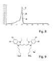
- la figure 8 présente des spectres d'absorption d'agrégats J sur des matrices de PAMAM G1, G4 et G6,
- la figure 9 montre la structure de la Myline 2,
- la figure 10 montre la structure d'une cyanine de type cation,
- la figure 11 illustre l'influence de la température de réaction sur la qualité des agrégats J obtenus, en montrant des spectres d'absorption d'agrégats J formés à différentes températures et déposés, en a, sur du PAMAM G4, et en b, sur du PAMAM G6,
- la figure 12 présente les spectres d'absorption d'une couche d'agrégats J obtenus selon l'invention en fonction du temps d'immersion dans la solution de Myline lors de l'étape de formation des agrégats J,
- la figure 13 est un spectre comparé des émissions de fluorescence d'agrégats J de Myline 1, après que ceux-ci aient été mis en contact avec des solutions de paraquat de concentrations variées,
- la figure 14 montre la structure d'une molécule acceptrice d'énergie,
- la figure 15 est un schéma d'un dispositif muni d'une source de lumière primaire et d'une source de lumière secondaire, selon l'invention, et
- les figures 16 et 17 présentent plusieurs variantes d'un dispositif comportant une source de lumière secondaire selon l'invention.
- FIG. 1 represents the structure of a Generation 4 dendrimer (PAMAM) (G4),
- Figures 2a and 2b give, respectively, an example of cyanines and mero-cyanines,
- Figure 3 shows the structure of Myline 1,
- FIGS. 4a and 4b compare, respectively, the absorption spectra of Myline 1 at different concentrations and aggregates J of Myline 1,
- FIG. 5 gives the absorption and emission spectra of aggregates J of Myline 1 on a PAMAM G4 matrix,
- FIG. 6 shows the aggregation absorption spectra J on PAMAM matrices G1, G4 and G6, made just after and 14 weeks after the formation of aggregates J,
- Figure 7 provides comparative absorption spectra of aggregates J formed on PAMAM G4 matrices and on polylysine matrices,
- FIG. 8 shows aggregation absorption spectra J on PAMAM matrices G1, G4 and G6,
- Figure 9 shows the structure of Myline 2,
- FIG. 10 shows the structure of a cyanine of cation type,
- FIG. 11 illustrates the influence of the reaction temperature on the quality of the J aggregates obtained, by showing absorption spectra of aggregates J formed at different temperatures and deposited, a , on PAMAM G4, and in b , on PAMAM G6,
- FIG. 12 shows the absorption spectra of a layer of aggregates J obtained according to the invention as a function of the immersion time in the Myline solution during the stage of formation of the aggregates J,
- FIG. 13 is a comparative spectrum of Myline 1 aggregates J fluorescence emissions after they have been contacted with paraquat solutions of various concentrations,
- FIG. 14 shows the structure of an energy accepting molecule,
- FIG. 15 is a diagram of a device provided with a primary light source and a secondary light source, according to the invention, and
- Figures 16 and 17 show several variants of a device comprising a secondary light source according to the invention.
Les différents spectres présentent l'absorption ou l'émission, en fonction de la longueur d'onde incidente ou émise.The different spectra show absorption or emission, depending on the incident or transmitted wavelength.
Un exemple de procédé de réalisation d'un agrégat J particulier va être décrit en détail ci-après, à titre d'illustration non limitative de l'invention. Comme on le comprendra, le procédé consiste essentiellement à revêtir un support préalablement préparé d'une matrice modèle, puis à déposer, sur cette matrice, les molécules de cyanines pour former l'agrégat J.An exemplary method of producing a particular aggregate J will be described in detail below, by way of non-limiting illustration of the invention. As will be understood, the method essentially consists in coating a previously prepared support with a model matrix and then depositing on this matrix the cyanine molecules to form the aggregate J.
Un support en verre, de type borosilicate, formant une plaque d'environ 3cm sur 1cm, est nettoyé, par exemple, par immersion dans une solution dite Piranha composée de H2SO4 et de H2O2, dans une proportion de 2 pour 1, à 120°C, pendant 10 minutes. Puis, le support est rincé avec de l'eau ultra pure et séché sous un courant d'azote. Le support est ensuite activé par un traitement avec un plasma d'oxygène, pendant 3 minutes. Ce plasma est créé entre deux plaques de condensateur, par induction d'un courant radiofréquence à travers les plaques. Les particules hautement énergétiques du plasma dégradent les éventuels résidus organiques subsistant sur le support en molécules volatiles qui s'évacuent. Le support est ainsi parfaitement nettoyé et est prêt pour les étapes suivantes.A borosilicate-type glass support, forming a plate approximately 3 cm by 1 cm, is cleaned, for example, by immersion in a so-called Piranha solution composed of H 2 SO 4 and H 2 O 2 , in a proportion of 2 for 1 at 120 ° C for 10 minutes. Then, the support is rinsed with ultra pure water and dried under a stream of nitrogen. The support is then activated by treatment with an oxygen plasma for 3 minutes. This plasma is created between two capacitor plates, by inducing a radiofrequency current through the plates. The highly energetic particles of the plasma degrade any organic residues remaining on the support in volatile molecules that evacuate. The media is perfectly cleaned and ready for the next steps.
Typiquement, une matrice modèle est réalisée à base de dendrimères, c'est-à-dire de macromolécules constituées, chacune, de monomères qui s'associent selon un processus arborescent autour d'un coeur central plurifonctionnel. La construction arborescente s'effectue par la répétition d'une même séquence de réactions jusqu'à l'obtention à la fin de chaque cycle réactionnel d'une nouvelle génération et d'un nombre croissant de branches identiques. Un exemple de dendrimère, du Polyamidoamide de quatrième génération, dénommé PAMAM G4, est représenté à la figure 1.Typically, a model matrix is made based on dendrimers, that is to say macromolecules each consisting of monomers that associate in a tree process around a central core multifunctional. The tree construction is carried out by repeating the same sequence of reactions until a new generation and an increasing number of identical branches are obtained at the end of each reaction cycle. An example of a dendrimer, fourth-generation polyamidoamide, called PAMAM G4, is shown in FIG.
Les dendrimères présentent l'avantage d'être monodisperses et de présenter une structure, une géométrie et une stoechiométrie rigoureusement contrôlées. En effet, le schéma réactionnel de leur préparation étant clairement défini, chacune des molécules d'un dendrimère donné est identique à une autre. Pour une molécule de dendrimère, le nombre de fonctions, la densité de charges, la surface et le volume occupé sont connus. Le tableau ci-après donne quelques exemples de dendrimères ainsi que leurs propriétés.
Le support préparé lors de l'étape précédente est plongé, pendant 18 heures, dans une solution éthanolique de PAMAM G4 concentrée à 1.10-4M. Grâce aux interactions entre le support et le PAMAM, celui-ci est adsorbé à la surface du support pour former sur ce dernier une monocouche homogène (voir, en particulier, l'article de
Dans l'exemple présenté, les réactions entre le PAMAM et le support sont de type acido-basique, entre les fonctions amines du PAMAM et les groupes silanols du verre, mais d'autres types d'interactions (électrostatiques, liaisons de Van der Waals, de type métal-ligand, etc....) peuvent également être mis en jeu, selon les différents supports choisis, comme il sera expliqué ci-après. Par ailleurs, d'autres techniques de dépôt peuvent être utilisées pour obtenir une monocouche homogène. Parmi ces techniques on peut citer : le "spin coating" ou dépôt sur un échantillon tournant, l'impression, le "spraying" ou pulvérisation, etc.In the example presented, the reactions between PAMAM and the support are of acid-base type, between the amine functions of PAMAM and the silanol groups of the glass, but other types of interactions (electrostatic, Van der Waals bonds). , metal-ligand type, etc. ....) can also be involved, depending on the various media chosen, as will be explained below. In addition, other deposition techniques can be used to obtain a homogeneous monolayer. These techniques include: "spin coating" or deposit on a rotating sample, printing, "spraying" or spraying, etc.
Puis, le support est rincé avec de l'éthanol pur afin d'éliminer les molécules de PAMAM non liées au support. Enfin, le support est séché sous un courant d'azote.Then, the support is rinsed with pure ethanol in order to eliminate the PAMAM molecules not bound to the support. Finally, the support is dried under a stream of nitrogen.
On obtient ainsi un ensemble composé d'un support, en verre en l'espèce, recouvert d'une monocouche régulière de dendrimères, du PAMAM selon l'exemple.This gives a set composed of a support, glass in this case, covered with a regular monolayer of dendrimers, PAMAM according to the example.
La cyanine utilisée pour former l'agrégat J est la [5, 5'-diphenyldibenzoxazolo N, N'-propylsulfonate]-9 ethyl trimethine cyanine (appelée Myline1), illustrée sur la figure 3. Ces cyanines étant sensibles à la lumière, il faut absolument éviter de les exposer à la lumière, tant lors de la préparation du réactif que lors de la réaction. La cyanine est mise en solution dans de l'acétone à une concentration de 7.10-4M. Le mélange est agité magnétiquement pendant 2 heures pour garantir la solubilisation totale du réactif.The cyanine used to form the aggregate J is [5,5'-diphenyldibenzoxazolo N, N'-propylsulfonate] -9 ethyl trimethine cyanine (called Myline1), illustrated in FIG. 3. These cyanines being sensitive to light, it is It is essential to avoid exposing them to light, both during the preparation of the reagent and during the reaction. The cyanine is dissolved in acetone at a concentration of 7 × 10 -4 M. The mixture is stirred magnetically for 2 hours to ensure complete solubilization of the reagent.
La cyanine proposée est chargée négativement. Aussi, pour lui permettre d'interagir avec le PAMAM déposé sur le support, celui-ci est préalablement immergé dans une solution acide, typiquement de l'acide chlorhydrique à pH 3,5 afin de protonner toutes les amines du PAMAM. Le support ainsi activé est ensuite plongé dans la solution de cyanine ci-dessus. La durée de l'immersion est comprise entre quelques secondes et quelques minutes, et sera discutée ci-après. Ensuite, le support est rincé par de l'acétone pur et séché sous un courant d'azote.The proposed cyanine is negatively charged. Also, to allow it to interact with PAMAM deposited on the support, it is previously immersed in an acid solution, typically hydrochloric acid at pH 3.5 to protonate all the amines PAMAM. The support thus activated is then immersed in the cyanine solution above. The duration of the immersion is between a few seconds and a few minutes, and will be discussed below. Then, the support is rinsed with pure acetone and dried under a stream of nitrogen.
On obtient ainsi un ensemble composé d'un support, en verre en l'espèce, recouvert d'une monocouche régulière de dendrimères, du PAMAM selon l'exemple, et d'une monocouche d'agrégats J.This gives a set composed of a support, in this case glass, covered with a regular monolayer of dendrimers, PAMAM according to the example, and a monolayer of aggregates J.
RésultatsResults
L'ensemble obtenu ci-dessus, particulièrement la couche de cyanines, est analysé au moyen d'un spectrophotomètre UV-visible. Le spectre obtenu avec une durée d'immersion de 12 minutes est présenté à la figure 4b, à comparer avec celui de la solution de Myline 1 utilisée comme réactif illustré sur la figure 4a.The assembly obtained above, particularly the cyanine layer, is analyzed by means of a UV-visible spectrophotometer. The spectrum obtained with an immersion time of 12 minutes is presented in FIG. 4b, to be compared with that of the Myline 1 solution used as the reagent illustrated in FIG. 4a.
L'étude de ce spectre (figure 4a) montre trois pics pour le réactif, à 479nm, 506nm et 551 nm, décrits dans la littérature comme correspondant respectivement aux pics d'absorption du dimère, du monomère et de l'agrégat J de Myline 1. Le spectre de la couche de Myline 1 déposée sur le support montre qu'il n'y a plus de dimère (absence de pic à 479nm) et presque plus de monomère (faible pic à 507nm). En revanche, le signal correspondant à l'agrégat J est très intense, ce qui signifie que la couche est presque exclusivement constituée d'agrégats J. Les longueurs d'onde du pic d'agrégat J obtenues selon le procédé ci-dessus et pour des échantillons de référence obtenus par la technique de Langmuir-Blodgett concordent de manière remarquable, attestant ainsi de la régularité et de la qualité, c'est-à-dire la haute organisation et la grande homogénéité, de l'agrégat J produit.The study of this spectrum (FIG. 4a) shows three peaks for the reagent, at 479 nm, 50 nm and 551 nm, described in the literature as respectively corresponding to the absorption peaks of the dimer, the monomer and the J aggregate of Myline. 1. The spectrum of the layer of Myline 1 deposited on the support shows that there is no more dimer (no peak at 479 nm) and almost no more monomer (low peak at 507 nm). On the other hand, the signal corresponding to the aggregate J is very intense, which means that the layer is almost exclusively composed of aggregates J. The wavelengths of the aggregate peak J obtained according to the process above and for reference samples obtained by the Langmuir-Blodgett technique agree remarkably, thus attesting to the regularity and quality, ie the high organization and the great homogeneity, of the aggregate J produced.
La qualité de l'organisation et de l'homogénéité des agrégats J formés est confirmée par la comparaison des longueurs d'onde d'émission de fluorescence et d'absorption de l'ensemble obtenu ci-dessus. Le spectre est présenté sur la figure 5. Le pic d'absorption a apparaît à une longueur d'onde de 549 nm, tandis que celui d'émission b apparaît à 554nm. Ce faible écart montre que la couche est homogène et parfaitement organisée à l'échelon moléculaire.The quality of the organization and the homogeneity of the aggregates J formed is confirmed by the comparison of the wavelengths of fluorescence emission and absorption of the assembly obtained above. The spectrum is shown in FIG. 5. The absorption peak a appears at a wavelength of 549 nm, whereas the emission peak b appears at 554 nm. This small difference shows that the layer is homogeneous and perfectly organized at the molecular level.
Un paramètre important, qui indique que le procédé décrit ci-dessus apporte un progrès important en vue de pouvoir appliquer industriellement les agrégats J, est la stabilité dans le temps des agrégats formés. La figure 6 présente les variations d'absorption pour un ensemble obtenu selon l'invention, avec un support en verre recouvert de PAMAM de différentes générations, respectivement G1, G4 et G6 pour les spectres 10, 11 et 12. Entre les différentes mesures, les échantillons ont été conservés dans l'obscurité. Les spectres indicés a sont obtenus juste après la réaction, tandis que les spectres indicés b ont été réalisés 14 semaines plus tard. On observe que, en absence de lumière, les agrégats J obtenus selon le procédé de l'invention, restent remarquablement organisés et même, que l'intensité des pics augmente légèrement. On peut penser que cet effet est dû à l'élimination de traces de solvant encore présentes juste après la réaction.An important parameter, which indicates that the process described above brings a significant progress in order to be able to industrially apply the aggregates J, is the stability over time of the aggregates formed. The FIG. 6 shows the absorption variations for an assembly obtained according to the invention, with a glass support covered with PAMAM of different generations, respectively G1, G4 and G6 for the
Pour démontrer l'efficacité et l'intérêt de l'utilisation d'un dendrimère par rapport à un polymère, un support de verre a été recouvert d'une couche de polylysine. Ce polymère comporte un grand nombre de fonctions amines et sa capacité à auto-arranger les molécules de Myline 1 en agrégats J peut donc être comparée avec celle observée pour le PAMAM. L'ensemble formé par un support de verre et une couche de polylysine subit le traitement décrit dans le paragraphe précédent relatif à la formation d'agrégats J.To demonstrate the effectiveness and utility of using a dendrimer versus a polymer, a glass carrier has been coated with a polylysine layer. This polymer has a large number of amine functional groups and its ability to self-arrange the Myline 1 molecules into J aggregates can therefore be compared with that observed for PAMAM. The assembly formed by a glass support and a polylysine layer undergoes the treatment described in the previous paragraph relating to the formation of aggregates J.
La figure 7 représente les spectres d'absorption UV d'une couche de Myline 1 déposées dans les conditions suivantes:
- a: déposée sur une couche de PAMAM G4, spectre effectué avant le dernier rinçage;
- b: déposée sur une couche de PAMAM G4, spectre effectué après le dernier rinçage réalisé à l'acétone;
- c: déposée sur une couche de polylysine, spectre effectué avant le dernier rinçage;
- d: déposée sur une couche de polylysine, spectre effectué après le dernier rinçage réalisé à l'eau.
- a: deposited on a PAMAM G4 layer, spectrum made before the last rinse;
- b: deposited on a PAMAM G4 layer, spectrum made after the last rinse performed with acetone;
- c: deposited on a polylysine layer, spectrum performed before the last rinse;
- d: deposited on a layer of polylysine, spectrum made after the last rinsing done with water.
La figure 7 montre que, avec une couche de polylysine, le pic d'absorption correspondant à l'agrégat J est mal défini (entre 530 et 544nm), moins intense et beaucoup plus large qu'avec une couche de PAMAM. De plus, le spectre d illustre que les molécules de cyanines ne sont pas stables sur la couche de polylysine et qu'elles se réorganisent sur cette surface. A contrario, ce comparatif prouve que les matrices de dendrimères, et en particulier celles fonctionnalisées avec le PAMAM, présentent une excellente capacité à auto-arranger les molécules de cyanines en agrégats J stables et hautement organisés et, par conséquent, aux propriétés optiques très proches des propriétés de référence.FIG. 7 shows that, with a polylysine layer, the absorption peak corresponding to the aggregate J is poorly defined (between 530 and 544 nm), less intense and much wider than with a PAMAM layer. Moreover, the spectrum d illustrates that the cyanine molecules are not stable on the polylysine layer and that they reorganize on this surface. On the other hand, this comparison proves that dendrimer matrices, and in particular those functionalized with PAMAM, have an excellent ability to self-arrange cyanine molecules into stable and highly organized aggregates and, consequently, to very close optical properties. reference properties.
D'autres tests comparatifs avec différents poids moléculaires des polymères de polylysine ont été menés, également avec différentes concentrations de cyanines en tant que réactif, sans présenter de meilleurs résultats.Other comparative tests with different molecular weights of polylysine polymers have been conducted, also with different concentrations of cyanines as reagent, without presenting better results.
D'autres supports ont été utilisés pour recevoir une couche de dendrimères. Notamment, des couches d'or ayant subi une activation par plasma d'oxygène, telle que décrite ci-dessus.Other supports have been used to receive a layer of dendrimers. In particular, gold layers having undergone activation by oxygen plasma, as described above.
Une couche de PAMAM est déposée selon le procédé décrit plus haut à propos d'un support de verre. Dans un solvant de type alcool de faible poids moléculaire (éthanol, méthanol, ...), le PAMAM adhère avec la surface d'or essentiellement grâce aux interactions entre les amines primaires périphériques du PAMAM et les atomes d'or de la surface. Le grand nombre de ces amines primaires permet d'obtenir une très bonne adhérence du PAMAM sur le support en or. Dans un solvant aqueux, la nature des interactions entre le PAMAM et l'or est très différente et est essentiellement contrôlée par des attractions électrostatiques. En effet, dans ces conditions, les groupements amines périphériques ont tendance à se protonner, chargeant positivement le PAMAM.A layer of PAMAM is deposited according to the method described above with regard to a glass support. In a low molecular weight alcohol solvent (ethanol, methanol, etc.), PAMAM adheres to the gold surface essentially through the interactions between the PAMAM peripheral primary amines and the surface gold atoms. The large number of these primary amines makes it possible to obtain a very good adhesion of PAMAM on the gold support. In an aqueous solvent, the nature of the interactions between PAMAM and gold is very different and is essentially controlled by electrostatic attractions. Indeed, under these conditions, the peripheral amine groups tend to protonate, positively charging PAMAM.
D'autres types de support peuvent encore être envisagés, tels que du silicium, du mica, du quartz ou des oxydes métalliques, notamment, ou même des supports souples de type polymère ou polycarbonate. L'essentiel étant que des interactions suffisantes puissent s'établir entre le support et la couche de dendrimères et que ces interactions soient de nature à permettre la création d'une monocouche de dendrimères sur le support. L'homme du métier sera à même, au moyen de simples expériences, d'établir d'autres associations entre des supports et des dendrimères, en faisant varier les groupes fonctionnels du dendrimère ou les conditions expérimentales du dépôt de la monocouche. Il convient également de noter la possibilité d'avoir une couche intermédiaire d'accrochage entre le support et la monocouche de dendrimères. Un exemple d'une telle couche intermédiaire peut être trouvé dans l'article de
Différents dendrimères ont été utilisés et peuvent convenir à l'application visée. Notamment, pour un dendrimère de type PAMAM, les générations 1, 4 et 6 ont été testées, permettant d'obtenir, en reproduisant le procédé décrit ci-dessus, les spectres d'absorption a, b, c, respectivement, représentés à la figure 8. Il ressort de ce comparatif que les générations plus élevées de dendrimères permettent d'obtenir un meilleur résultat, sans doute grâce au fait qu'elles présentent une plus haute densité de groupes fonctionnels en périphérie. Ainsi, il est probable que des PAMAM de générations supérieures à 6, notamment jusqu'à la génération 10 au moins, offrent d'excellents résultats.Different dendrimers have been used and may be suitable for the intended application. In particular, for a PAMAM type dendrimer, the generations 1, 4 and 6 have been tested, making it possible to obtain, by reproducing the process described above, the absorption spectra a, b, c, respectively, represented in FIG. Figure 8. It is apparent from this comparison that higher generations of dendrimers achieve a better result, probably because they have a higher density of functional groups at the periphery. Thus, it is likely that PAMAMs of generations greater than 6, especially up to at
De manière plus générale, divers types de PAMAM peuvent être utilisés, qu'ils soient chargés positivement ou négativement. D'autres dendrimères, tels que des PAMAM G3.5, G4.5, ... , Gm.5, ... avec des fonctions périphériques carboxyliques (COOH) ou carboxylates (COO-), forment également des matrices permettant à des cyanines de s'auto-arranger en agrégats J. La caractéristique essentielle que doit présenter la molécule formant la matrice modèle est que sa surface extérieure, c'est-à-dire celle formant l'interface avec le milieu réactionnel lorsqu'elle est sur le support, doit être définie et régulière. Elle doit, en outre, disposer d'une haute densité de groupes fonctionnels périphériques pour interagir efficacement avec le support afin d'y être adsorbée mais aussi pour réagir avec des colorants pour leur permettre de s'auto-organiser librement. L'homme du métier saura faire les expérimentations nécessaires pour tester de manière large des macromolécules hyperbranches, comprenant des dendrimères, mais aussi des polymères hyperbranches, c'est-à-dire des molécules comportant une partie de type polymère, faiblement organisée, et une partie de type dendrimère, bien définie. De tels polymères hyperbranches peuvent convenir dans la mesure où la partie polymère est utilisée pour lier cette molécule au support, la partie dendrimère étant alors à l'interface avec les molécules de colorants. Dans le cadre de la présente invention de tels polymères hyperbranches sont réputés faire partie de la famille des dendrimères.More generally, various types of PAMAM can be used, whether positively or negatively charged. Other dendrimers, such as PAMAM G3.5, G4.5,..., Gm.5,... With carboxylic peripheral functions (COOH) or carboxylate functions (COO-), also form matrices allowing The essential characteristic that the molecule forming the model matrix must exhibit is that its outer surface, that is to say the one forming the interface with the reaction medium when it is on the support, must be defined and regular. It must, in addition, have a high density of peripheral functional groups to interact effectively with the support to be adsorbed therein but also to react with dyes to allow them to self-organize freely. The skilled person will be able to make the necessary experiments to test Broadly speaking, hyperbranch macromolecules, including dendrimers, but also hyperbranch polymers, that is to say molecules having a polymer type part, weakly organized, and a dendrimer part, well-defined. Such hyperbranch polymers may be suitable insofar as the polymer part is used to bind this molecule to the support, the dendrimer part then being at the interface with the dye molecules. In the context of the present invention, such hyperbranch polymers are deemed to be part of the family of dendrimers.
Les différents colorants englobés dans la définition de la famille des cyanines donnée ci-dessus, c'est-à-dire les cyanines, les méro-cyanines et leurs dérivés, sont susceptibles de s'auto-arranger pour former des agrégats J sur une matrice modèle telle que définie aux paragraphes précédents. Bien entendu, la cyanine et la molécule formant la matrice modèle doivent être choisies l'une en fonction de l'autre pour que la cyanine interagisse avec les groupes fonctionnels présents à la périphérie de la matrice modèle ; ce qui implique, par exemple, une complémentarité des charges électriques et une similitude des densités de charges.The various dyes included in the definition of the cyanine family given above, that is to say the cyanines, the mero-cyanines and their derivatives, are capable of self-arranging to form aggregates J on a model matrix as defined in the preceding paragraphs. Of course, the cyanine and the molecule forming the model matrix must be chosen in relation to each other so that the cyanine interacts with the functional groups present at the periphery of the model matrix; which implies, for example, a complementarity of the electric charges and a similarity of the densities of charges.
La [5,5'-tétrachloro1,1'diéthyle-dibenzoxazolo-N-N'-propionatebutylsufonate] triméthine cyanine, appelée Myline 2 et représentée sur la figure 9, a été déposée sur une matrice modèle en PAMAM G4, déposée sur un support en or. La Myline 2 a été utilisée sous forme anionique, en solution dans de l'acétone à 7.10-4M. Le PAMAM ayant été protonné, ainsi que décrit ci-dessus, la matrice modèle est plongée 3 minutes dans la solution de Myline 2. La formation d'agrégats J a été observée, confirmée par la présence d'un pic d'absorption à 586nm.The [5,5'-tetrachloro1,1'-diethyl-dibenzoxazolo-N-N'-propionatebutylsufonate] trimethine cyanine, called Myline 2 and shown in FIG. 9, was deposited on a model matrix made of PAMAM G4, deposited on a support Golden. The Myline 2 was used in anionic form, in solution in acetone at 7 × 10 -4 M. The PAMAM having been protonated, as described above, the model matrix is immersed for 3 minutes in the Myline 2 solution. Aggregate formation was observed, confirmed by the presence of an absorption peak at 586 nm.
De manière analogue, une cyanine de type cation peut également s'auto-arranger pour former des agrégats J sur une matrice modèle chargée négativement. Un exemple d'une telle cyanine est illustré à la figure 10 alors qu'un dendrimère chargé négativement peut, par exemple, être un PAMAM de génération, Gm.5 avec fonctions périphériques carboxylates.Similarly, a cation-like cyanine can also self-arrange to form aggregates J on a negatively charged model template. An example of such a cyanine is shown in Figure 10 while a negatively charged dendrimer may, for example, be a generation PAMAM, Gm.5 with carboxylate peripheral functions.
Les solvants interviennent à deux étapes du procédé réactionnel. Tout d'abord, le dendrimère est dissous dans un premier solvant. Comme déjà évoqué ci-dessus, ce premier solvant est, de préférence, un alcool de faible poids moléculaire, notamment du méthanol ou de l'éthanol.Solvents occur at two stages of the reaction process. First, the dendrimer is dissolved in a first solvent. As already mentioned above, this first solvent is preferably a low molecular weight alcohol, especially methanol or ethanol.
Ensuite, le colorant est dissous dans un deuxième solvant. Dans l'exemple, ce dernier est de l'acétone. Des expériences menées avec un mélange d'acétone et d'éthanol, notamment un mélange 1:1, ont donné de bons résultats.Then, the dye is dissolved in a second solvent. In the example, the latter is acetone. Experiments conducted with a mixture of acetone and ethanol, especially a 1: 1 mixture, gave good results.
Les nombreuses expériences qui ont été menées pour tester différentes variantes susceptibles d'être mises en oeuvre dans le procédé selon l'invention ont permis d'identifier certains paramètres permettant soit d'obtenir des agrégats J de qualité supérieure, soit de faciliter le procédé en lui-même. Il est bien entendu que les paragraphes qui suivent donnent des sélections mais ne constituent pas des limitations visant à exclure les éléments ou domaines qui ne seraient pas compris dans ces sélections.The numerous experiments that have been conducted to test different variants that can be implemented in the process according to the invention have made it possible to identify certain parameters that make it possible to obtain aggregates J of superior quality, or to facilitate the process by himself. It is understood that the following paragraphs provide selections but do not constitute limitations to exclude items or domains that are not included in these selections.
Ainsi, il apparaît que la solution de cyanines utilisée lors de la formation d'agrégats J donne une meilleure conversion des molécules de cyanines en agrégats J si la concentration en cyanines est suffisante, c'est-à-dire voisine de la saturation, de manière à permettre la formation de noyaux d'agrégats J dans la solution, qui vont agir comme germes dans le processus ultérieur de croissance de l'agrégat J. La valeur du seuil de saturation dépend bien sûr du solvant utilisé et de la nature de la cyanine considérée. Avec de l'acétone comme solvant et la cyanine Myline 1, il est donc souhaitable que la concentration soit égale ou supérieure à 7.10-5M.Thus, it appears that the cyanine solution used during the formation of aggregates J gives a better conversion of the cyanine molecules into aggregates J if the concentration of cyanines is sufficient, that is to say close to the saturation, of to allow the formation of J aggregates in the solution, which will act as seeds in the subsequent growth process of the aggregate J. The value of the saturation threshold depends of course on the solvent used and the nature of the cyanine considered. With acetone as solvent and cyanine Myline 1, it is therefore desirable that the concentration be equal to or greater than 7.10 -5 M.
L'étape de formation d'agrégats J a été menée en portant la solution de cyanines à différentes températures, soit à température ambiante (22°C), à 40°C et à 55°C. Ces différents essais ont été reproduits avec une matrice modèle réalisée à base de PAMAM G4 et de PAMAM G6. Les spectres d'absorption obtenus sont représentés sur les figures 11a et 11b, respectivement pour le PAMAM G4 et le PAMAM G6. Les courbes a, b, c correspondent aux températures 22, 40 et 55 °C.The aggregation step J was conducted by carrying the cyanine solution at various temperatures, at room temperature (22 ° C), 40 ° C and 55 ° C. These different tests were reproduced with a model matrix made from PAMAM G4 and PAMAM G6. The absorption spectra obtained are shown in FIGS. 11a and 11b, respectively for PAMAM G4 and PAMAM G6. The curves a, b, c correspond to the temperatures 22, 40 and 55 ° C.
L'influence de la durée de l'immersion du support recouvert de la matrice modèle dans la solution de cyanines lors de l'étape de formation d'agrégats J a aussi été explorée. Des durées variant de 15 secondes à 12 minutes ont été testées, avec un support d'or recouvert d'une couche de PAMAM G4, acidifié et plongé dans une solution d'acétone contenant de la Myline 1 à 7.10-4M. Les spectres obtenus sont représentés sur la figure 12. Les spectres a, b, c, d, e, f, g, h, et i correspondent, respectivement, à des durées de 15, 30 45, 60, 90, 180 secondes, 6, 9 et 12 minutes. Ils montrent qu'un pic correspondant à la formation d'agrégats J peut déjà être observé après seulement 15 secondes. L'absorption maximale est atteinte pour une durée d'immersion de 3 minutes. Par contre, la plus petite largeur de pic à mi-hauteur est obtenue pour une durée de 12 minutes.The influence of the duration of the immersion of the support covered with the model matrix in the cyanine solution during the step of formation of aggregates J was also explored. Times ranging from 15 seconds to 12 minutes were tested, with a gold support covered with a layer of PAMAM G4, acidified and immersed in an acetone solution containing Myline 1 at 7 × 10 -4 M. Spectra The spectra a, b, c, d, e, f, g, h, and i respectively correspond to durations of 15, 30, 45, 60, 90, 180 seconds, 6, 9 and 12 minutes. They show that a peak corresponding to the formation of aggregates J can already be observed after only 15 seconds. The maximum absorption is reached for an immersion time of 3 minutes. On the other hand, the smallest peak width at half height is obtained for a duration of 12 minutes.
Comme mentionné précédemment, l'une des propriétés des agrégats J est de permettre la circulation extrêmement rapide et, quasiment, sans perte d'énergie, d'un exciton ou d'un électron. Ainsi, si des agrégats J de cyanines sont excités, toutes les molécules de cyanines vont émettre une fluorescence de résonance avec une forte intensité.As mentioned above, one of the properties of aggregates J is to allow the extremely fast circulation and, almost without loss of energy, an exciton or an electron. Thus, if aggregates J of cyanines are excited, all the cyanine molecules will emit resonance fluorescence with a high intensity.
La présente application repose sur le fait que, si une molécule acceptrice d'électron est présente dans l'environnement de l'agrégat J, les excitons délocalisés dans l'agrégat J seront rapidement capturés par l'accepteur qui les transformera en paires électron/trou, ce qui aura pour conséquence l'extinction de la fluorescence d'émission.The present application is based on the fact that, if an electron-accepting molecule is present in the environment of the aggregate J, the excitons delocalized in the aggregate J will be rapidly captured by the acceptor which will transform them into electron pairs. hole, which will result in the extinction of the emission fluorescence.
Des expériences ont été menées avec, comme molécule acceptrice d'électron, du 1,1'-diméthyl-4,4'-bipyridinium, connu sous le nom de paraquat, pour une utilisation en tant qu'herbicide. Le paraquat est également un toxique puissant, s'attaquant notamment au système nerveux central. Il est donc particulièrement important de pouvoir en détecter d'éventuelles traces sur les cultures qui ont été traitées.Experiments have been conducted with 1,1'-dimethyl-4,4'-bipyridinium, known as paraquat, as an electron acceptor molecule for use as a herbicide. Paraquat is also a potent toxin, particularly attacking the central nervous system. It is therefore particularly important to be able to detect any traces on crops that have been treated.
Des agrégats J de Myline 1 sont préparés selon le procédé décrit ci-dessus, sur des supports de verre recouverts d'une matrice modèle de PAMAM G4. L'ensemble obtenu est ensuite plongé pendant 1 heure dans des solutions aqueuses de paraquat, à différentes concentrations. Ensuite, les agrégats J sont excités par une source de longueur d'onde à 510nm et les spectres d'émission de fluorescence représentés à la figure 13 sont obtenus. Ils montrent l'intensité d'émission dans une unité arbitraire en fonction de la longueur d'onde, pour:
- a: un échantillon de référence n'ayant pas été au contact de paraquat,
- b: un échantillon ayant été trempé dans une solution de paraquat à 4.10-4M,
- c: un échantillon ayant été trempé dans une solution de paraquat à 40.10-6M, et
- d: un échantillon ayant été trempé dans une solution de paraquat à 1.10-6M.
- a: a reference sample that has not been in contact with paraquat,
- b: a sample having been soaked in a solution of paraquat at 4 × 10 -4 M,
- c: a sample having been soaked in a paraquat solution at 40 × 10 -6 M, and
- d: a sample having been soaked in a solution of paraquat at 1.10 -6 M.
Ces résultats confirment bien que la présence d'une molécule acceptrice d'électron peut être détectée par une réduction de l'émission de fluorescence d'agrégats J. La réduction de fluorescence observée pour une concentration de 1.10-6M est d'environ 50%, ce qui permet d'envisager de détecter, avec encore suffisamment de précision, des concentrations beaucoup plus faibles.These results confirm that the presence of an electron acceptor molecule can be detected by a reduction in the fluorescence emission of aggregates J. The reduction in fluorescence observed for a concentration of 1.10 -6 M is approximately 50 %, which makes it possible to consider detecting, with sufficient precision, much lower concentrations.
Dans le prolongement de ce qui a été mentionné ci-dessus à propos du paraquat, on peut envisager d'intégrer une molécule acceptrice d'énergie directement à l'intérieur même de l'agrégat J. En choisissant un accepteur d'énergie luminescent, dont le spectre d'absorption recouvre, au moins partiellement, le spectre d'émission de l'agrégat, cet accepteur va récolter, avec un certain rendement, l'énergie d'excitation de l'agrégat et réémettre à sa propre longueur d'onde d'émission. Par exemple, un tel accepteur, pouvant convenir pour être incorporé dans un agrégat de molécules de Myline 1, peut être tel que représenté à la figure 14. Une telle molécule a les propriétés nécessaires pour le transfert d'énergie souhaité (maximum d'absorption vers 550 nm, émission vers 600 nm).As an extension of what has been mentioned above about paraquat, it is conceivable to integrate an energy acceptor molecule directly inside the aggregate J. By choosing a luminescent energy acceptor, whose absorption spectrum covers, at least partially, the emission spectrum of the aggregate, this acceptor will harvest, with a certain yield, the excitation energy of the aggregate and re-emit at its own length. emission wave. For example, such an acceptor, which may be suitable for incorporation into an aggregate of Myline 1 molecules, may be as shown in FIG. the properties necessary for the desired energy transfer (absorption maximum around 550 nm, emission around 600 nm).
Pour obtenir une répartition homogène de l'accepteur dans l'agrégat J, les molécules acceptrices d'énergie sont dissoutes dans la solution-mère de cyanines utilisée pour la formation des agrégats J.To obtain a homogeneous distribution of the acceptor in aggregate J, the energy-accepting molecules are dissolved in the cyanine master solution used for the formation of aggregates J.
Ce mode d'utilisation des agrégats J peut notamment trouver une application particulièrement intéressante dans des dispositifs comportant des guides d'onde ou d'autres composés optiques. En effet, il peut être souhaitable d'intégrer, dans un tel dispositif, une source de lumière capable d'injecter une onde lumineuse dans le guide d'onde dudit dispositif. Une telle intégration est rendue possible grâce au procédé selon l'invention. Le dispositif ainsi obtenu est représenté à la figure 15. Un guide d'onde 24, par exemple en Ta2O5, est réalisé, de manière conventionnelle, dans un substrat en verre 23. Sur le guide d'onde sont ensuite déposées, en utilisant le procédé de l'invention, une couche de dendrimères puis une couche d'agrégats J dans laquelle ont été intégrées des molécules acceptrices d'énergie et luminescentes. Ces couches, ainsi déposées et formant une source de lumière secondaire 28, sont recouvertes par une couche transparente séparatrice 26, par exemple en verre. Enfin, une source de lumière primaire 30 est réalisée sur la couche transparente 26 en regard de la source de lumière secondaire 28. En variante, la couche séparatrice peut être un milieu transparent tel que l'air.This mode of use of aggregates J may especially find a particularly advantageous application in devices comprising waveguides or other optical compounds. Indeed, it may be desirable to integrate, in such a device, a light source capable of injecting a light wave into the waveguide of said device. Such integration is made possible by the method according to the invention. The device thus obtained is shown in FIG. 15. A
Comme indiqué plus haut, les molécules acceptrices d'énergie sont capables de récolter la lumière reçue, à une première longueur d'onde, de la source primaire 30 et de réémettre, à une deuxième longueur d'onde différente de la première, dans le guide d'onde 24. Dépendant de l'intensité de l'onde excitatrice, l'émission à la deuxième longueur d'onde peut être soit spontanée, soit stimulée. Le dernier cas (effet laser) se produit lorsque l'excitation à la première longueur d'onde est suffisamment intense pour entraîner une inversion de population des accepteurs d'énergie, ce qui veut dire que plus de 50% des accepteurs d'énergie sont excités à tout moment.As indicated above, the energy accepting molecules are capable of harvesting the light received, at a first wavelength, from the
Il est particulièrement important que la longueur d'onde d'émission de l'accepteur d'énergie soit suffisamment éloignée de celle d'absorption des agrégats J, pour éviter que la lumière émise par les accepteurs soit absorbée par l'agrégat au lieu d'être conduite par le guide d'onde. Les longueurs d'onde sont, par exemple, séparées d'au moins 20nm, particulièrement d'environ 50 à 70 nm.It is particularly important that the emission wavelength of the energy acceptor is sufficiently far removed from that of the J aggregates absorption, to avoid that the light emitted by the acceptors is absorbed by the aggregate instead of be driven by the waveguide. The wavelengths are, for example, separated by at least 20 nm, particularly from about 50 to 70 nm.
Cette source secondaire 28 est destinée à être excitée par une source de lumière primaire 30 qui peut être positionnée de plusieurs manières, comme décrit en détails ci-après.This
Dans le dispositif de la figure 15, l'ensemble constitué par le guide d'onde 24 et par la source de lumière secondaire 28 est intégré à l'intérieur d'un dispositif 23. Plus particulièrement, la source secondaire 28 est recouverte d'un séparateur transparent 26, par exemple réalisé en verre, la source primaire 30 étant positionnée directement sur le séparateur 26. Cette source primaire 30 peut être une LED, une OLED ou encore une autre source de lumière connue.In the device of FIG. 15, the assembly formed by the
Dans le dispositif de la figure 16, l'ensemble constitué par le guide d'onde 24 et par la source de lumière secondaire 28 constitue la couche supérieure d'un dispositif 23. La source de lumière primaire 30 est située à distance du dispositif et peut être positionnée de manière indifférente par rapport à la source secondaire, comme le montrent les différentes positions illustrées, tant que la lumière qu'elle émet atteint la source secondaire, y compris à travers le substrat et le guide d'onde 24 du dispositif 23.In the device of FIG. 16, the assembly formed by the
Enfin, la figure 17 propose différentes variantes de la position de la source de lumière secondaire 28 par rapport au guide d'onde 24. On a représenté en 32 le profil du mode de transmission du guide d'onde. La source secondaire 28 peut être placée n'importe où à l'intérieur du profil de mode. Autrement dit, elle doit être située dans la région où le champ électromagnétique de l'onde guidée est augmenté par le guide d'onde. Il est également possible de combiner plusieurs sources secondaires, situées à des positions différentes, ces différentes sources pouvant absorber et/ou réémettre à différentes longueurs d'onde, selon l'application et les matériaux choisis.Finally, FIG. 17 proposes different variants of the position of the secondary
Dans une autre variante non représentée, l'homme du métier peut imaginer que l'accepteur luminescent soit localisé à un endroit précis de l'agrégat J au lieu d'y être réparti de manière homogène. Dans ce cas, lorsqu'un endroit de l'agrégat J est irradié par une source lumineuse, la zone comportant l'accepteur va absorber l'énergie se déplaçant dans l'agrégat et seule cette zone va émettre de la lumière.In another variant not shown, one skilled in the art can imagine that the luminescent acceptor is located at a specific location of the aggregate J instead of being distributed homogeneously. In this case, when a location of the aggregate J is irradiated by a light source, the zone comprising the acceptor will absorb the energy moving in the aggregate and only this area will emit light.
Ainsi est proposé un procédé particulièrement simple, permettant d'obtenir des agrégats J de très haute qualité, très stables et pouvant être mis en oeuvre dans des applications industrielles. Notamment, l'invention porte sur l'une de ces applications à des dispositifs optiques. Les techniques décrites ci-dessus ouvrent de larges perspectives en terme d'expérimentation, pour les appliquer à d'autres macromolécules hyperbranches, à d'autres substrats ou à d'autres types de colorants susceptibles de former des agrégats J. La portée de l'invention ne se limite donc pas aux espèces chimiques mentionnées dans les exemples particuliers.Thus is proposed a particularly simple process, to obtain J aggregates of very high quality, very stable and can be implemented in industrial applications. In particular, the invention relates to one of these applications to optical devices. The techniques described above open wide perspectives in terms of experimentation, to apply them to other hyperbranch macromolecules, other substrates or other types of dyes capable of forming aggregates J. The scope of the The invention is therefore not limited to the chemical species mentioned in the particular examples.
Claims (28)
Applications Claiming Priority (1)
| Application Number | Priority Date | Filing Date | Title |
|---|---|---|---|
| CH01838/05A CH703675B1 (en) | 2005-11-16 | 2005-11-16 | Process for producing J aggregates |
Publications (2)
| Publication Number | Publication Date |
|---|---|
| EP1788036A1 true EP1788036A1 (en) | 2007-05-23 |
| EP1788036B1 EP1788036B1 (en) | 2011-09-28 |
Family
ID=37946143
Family Applications (1)
| Application Number | Title | Priority Date | Filing Date |
|---|---|---|---|
| EP05111790A Active EP1788036B1 (en) | 2005-11-16 | 2005-12-07 | Process for the preparation of J-aggregates |
Country Status (5)
| Country | Link |
|---|---|
| US (1) | US8088929B2 (en) |
| EP (1) | EP1788036B1 (en) |
| AT (1) | ATE526368T1 (en) |
| CH (1) | CH703675B1 (en) |
| WO (1) | WO2007057356A2 (en) |
Cited By (2)
| Publication number | Priority date | Publication date | Assignee | Title |
|---|---|---|---|---|
| EP2028236A1 (en) * | 2007-08-23 | 2009-02-25 | CSEM Centre Suisse d'Electronique et de Microtechnique SA Recherche et Développement | Composition comprising J-aggregates |
| EP2684839A1 (en) | 2012-07-13 | 2014-01-15 | CSEM Centre Suisse d'Electronique et de Microtechnique SA - Recherche et Développement | Mesoporous coating comprising j-aggregates |
Citations (2)
| Publication number | Priority date | Publication date | Assignee | Title |
|---|---|---|---|---|
| EP1081557A1 (en) * | 1999-09-03 | 2001-03-07 | Sharp Kabushiki Kaisha | Electrophotographic photoreceptor, coating liquid for photosensitive layer, method for producing the same and image-forming apparatus using the electrophotographic photoreceptor |
| EP1085315A1 (en) * | 1999-09-15 | 2001-03-21 | CSEM Centre Suisse d'Electronique et de Microtechnique SA | Integrated-optical sensor |
Family Cites Families (6)
| Publication number | Priority date | Publication date | Assignee | Title |
|---|---|---|---|---|
| DE19855180A1 (en) * | 1998-11-30 | 2000-05-31 | Metabion Gmbh Ges Fuer Angewan | in situ hybridization method |
| EP1978110B1 (en) * | 2000-09-06 | 2010-05-26 | Transnetyx, Inc. | Computer-based method and system for screening genomic DNA |
| US20040023248A1 (en) * | 2001-12-07 | 2004-02-05 | Whitehead Institiute For Biomedical Research | Methods and reagents for improving nucleic acid detection |
| US7261875B2 (en) * | 2001-12-21 | 2007-08-28 | Board Of Regents, The University Of Texas System | Dendritic poly (amino acid) carriers and methods of use |
| US7271265B2 (en) * | 2003-08-11 | 2007-09-18 | Invitrogen Corporation | Cyanine compounds and their application as quenching compounds |
| EP2028236B1 (en) * | 2007-08-23 | 2010-08-11 | CSEM Centre Suisse d'Electronique et de Microtechnique SA - Recherche et Développement | Composition comprising J-aggregates |
-
2005
- 2005-11-16 CH CH01838/05A patent/CH703675B1/en not_active IP Right Cessation
- 2005-12-07 EP EP05111790A patent/EP1788036B1/en active Active
- 2005-12-07 AT AT05111790T patent/ATE526368T1/en not_active IP Right Cessation
-
2006
- 2006-11-10 WO PCT/EP2006/068340 patent/WO2007057356A2/en active Application Filing
- 2006-11-10 US US12/094,038 patent/US8088929B2/en active Active
Patent Citations (2)
| Publication number | Priority date | Publication date | Assignee | Title |
|---|---|---|---|---|
| EP1081557A1 (en) * | 1999-09-03 | 2001-03-07 | Sharp Kabushiki Kaisha | Electrophotographic photoreceptor, coating liquid for photosensitive layer, method for producing the same and image-forming apparatus using the electrophotographic photoreceptor |
| EP1085315A1 (en) * | 1999-09-15 | 2001-03-21 | CSEM Centre Suisse d'Electronique et de Microtechnique SA | Integrated-optical sensor |
Non-Patent Citations (3)
| Title |
|---|
| HIDEO TOKUHISA ET. AL.: "Preparation and Characterization of Dendrimer Monolayers and Dendrimer-Alkanethiol Mixed Monolayers Adsorbed to Gold", JOURNAL OF THE AMERICAN CHEMICAL SOCIETY, vol. 120, 1998, pages 4492 - 4501, XP002417618 * |
| M. LOSSON: "Self-organizing properties of dendrimers and potential applications; Thèse pur l'obtention du titre de Docteur ès Sciences", 24 October 2005, UNIVERSITÉ DE NEUCHATEL; FACULTE DES SCIENCES, NEUCHATEL, XP002417620 * |
| R. STEIGER; F. ZBINDEN: "Physical-Chemical Properties of Organized Sensitizer Molecules", JOURNAL OF IMAGING SCIENCE, vol. 32, 1988, pages 64 - 81, XP008074432 * |
Cited By (4)
| Publication number | Priority date | Publication date | Assignee | Title |
|---|---|---|---|---|
| EP2028236A1 (en) * | 2007-08-23 | 2009-02-25 | CSEM Centre Suisse d'Electronique et de Microtechnique SA Recherche et Développement | Composition comprising J-aggregates |
| US7824617B2 (en) | 2007-08-23 | 2010-11-02 | CSEM Centre Suisse d'Electronique et de Microtechnique SA-Recherche et Development | Assembly comprising J aggregates |
| EP2684839A1 (en) | 2012-07-13 | 2014-01-15 | CSEM Centre Suisse d'Electronique et de Microtechnique SA - Recherche et Développement | Mesoporous coating comprising j-aggregates |
| EP2708492A1 (en) | 2012-07-13 | 2014-03-19 | CSEM Centre Suisse d'Electronique et de Microtechnique SA - Recherche et Développement | Mesoporous layer comprising J-aggregates |
Also Published As
| Publication number | Publication date |
|---|---|
| WO2007057356A2 (en) | 2007-05-24 |
| EP1788036B1 (en) | 2011-09-28 |
| US20080279500A1 (en) | 2008-11-13 |
| WO2007057356A3 (en) | 2007-08-23 |
| CH703675B1 (en) | 2012-03-15 |
| US8088929B2 (en) | 2012-01-03 |
| ATE526368T1 (en) | 2011-10-15 |
Similar Documents
| Publication | Publication Date | Title |
|---|---|---|
| EP2652533B1 (en) | Optical element comprising a crack-free aerogel | |
| Huijser et al. | Photosensitization of TiO2 and SnO2 by artificial self-assembling mimics of the natural chlorosomal bacteriochlorophylls | |
| EP4082052A1 (en) | Photovoltaic module | |
| EP0191661A1 (en) | Coating and crystallisation process of an organic-material film by the use of a beam of energy | |
| EP0130117B1 (en) | Luminescent material having a solid matrix with a luminescent compound distributed inside, process for its manufacture and its use in a photopile | |
| WO2009125086A1 (en) | Fluorescent nanocrystals encapsulated in an inorganic shell | |
| EP2550679B1 (en) | Photovoltaic devices comprising an anti-reflective layer containing dispersed objects having areas with different refractive indices | |
| EP1788036B1 (en) | Process for the preparation of J-aggregates | |
| WO2020002857A1 (en) | Photovoltaic cell and method for manufacturing same | |
| EP2028236B1 (en) | Composition comprising J-aggregates | |
| EP1704607B1 (en) | Inorganic/organic semiconductor p-n hybrid material, production method thereof and photovoltaic cell comprising same | |
| EP3221042B1 (en) | Method for preparing a colloidal solution of nanoparticles of a mixed oxide of vanadium and europium or a mixed oxide of vanadium, europium and yttrium. | |
| EP2596498B1 (en) | Method for the thermal photoswitching of spin-transition materials, and uses thereof | |
| EP4178989A1 (en) | Initiator molecule for a non linear absorption reaction, photopolymerisable composition that can be activated by biphotonic absorption and associated 3d printing method | |
| FR2939794A1 (en) | ORGANIC REDOX ACTIVE COMPOUNDS WITH REVERSIBLE CHARGE STORAGE AND SUBSTRATES AND MOLECULAR MEMORY DEVICES INCLUDING THE SAME | |
| EP3364461A1 (en) | Method for doping graphene | |
| EP2691404B1 (en) | Use of cobalt complexes for the preparation of the active layer of a photvoltaic cell, and corresponding photovoltaic cell | |
| EP3470368A1 (en) | Method for doping carbon nanotubes | |
| WO2013054024A1 (en) | Method for detecting the interaction of at least one entity with a dielectric layer | |
| CA2816251A1 (en) | Electrical conduction by means of supramolecular assemblies of triarylamines | |
| CN113113546A (en) | Photoelectric transistor and preparation method thereof | |
| Samsonova et al. | Lasing of a DCM dye layer in carbazole-based films | |
| FR3069542A1 (en) | CROSS-LINKING AGENT OF A RESIN | |
| FR2930937A1 (en) | SURFACE TREATMENT OF SILICON NANOPARTICLES | |
| FR2992107A1 (en) | ORGANIC LASER SYSTEM AND METHOD OF MODIFYING THE TRANSMIT WAVE LENGTH OF THE LASER SYSTEM |
Legal Events
| Date | Code | Title | Description |
|---|---|---|---|
| PUAI | Public reference made under article 153(3) epc to a published international application that has entered the european phase |
Free format text: ORIGINAL CODE: 0009012 |
|
| AK | Designated contracting states |
Kind code of ref document: A1 Designated state(s): AT BE BG CH CY CZ DE DK EE ES FI FR GB GR HU IE IS IT LI LT LU LV MC NL PL PT RO SE SI SK TR |
|
| AX | Request for extension of the european patent |
Extension state: AL BA HR MK YU |
|
| 17P | Request for examination filed |
Effective date: 20071109 |
|
| AKX | Designation fees paid |
Designated state(s): AT BE BG CH CY CZ DE DK EE ES FI FR GB GR HU IE IS IT LI LT LU LV MC NL PL PT RO SE SI SK TR |
|
| GRAP | Despatch of communication of intention to grant a patent |
Free format text: ORIGINAL CODE: EPIDOSNIGR1 |
|
| GRAS | Grant fee paid |
Free format text: ORIGINAL CODE: EPIDOSNIGR3 |
|
| GRAA | (expected) grant |
Free format text: ORIGINAL CODE: 0009210 |
|
| RAP1 | Party data changed (applicant data changed or rights of an application transferred) |
Owner name: CSEM CENTRE SUISSE D'ELECTRONIQUE ET DE MICROTECHN |
|
| AK | Designated contracting states |
Kind code of ref document: B1 Designated state(s): AT BE BG CH CY CZ DE DK EE ES FI FR GB GR HU IE IS IT LI LT LU LV MC NL PL PT RO SE SI SK TR |
|
| REG | Reference to a national code |
Ref country code: GB Ref legal event code: FG4D Free format text: NOT ENGLISH |
|
| REG | Reference to a national code |
Ref country code: CH Ref legal event code: EP |
|
| REG | Reference to a national code |
Ref country code: IE Ref legal event code: FG4D |
|
| REG | Reference to a national code |
Ref country code: CH Ref legal event code: NV Representative=s name: GLN S.A. |
|
| REG | Reference to a national code |
Ref country code: DE Ref legal event code: R096 Ref document number: 602005030202 Country of ref document: DE Effective date: 20111201 |
|
| REG | Reference to a national code |
Ref country code: NL Ref legal event code: VDEP Effective date: 20110928 |
|
| PG25 | Lapsed in a contracting state [announced via postgrant information from national office to epo] |
Ref country code: SE Free format text: LAPSE BECAUSE OF FAILURE TO SUBMIT A TRANSLATION OF THE DESCRIPTION OR TO PAY THE FEE WITHIN THE PRESCRIBED TIME-LIMIT Effective date: 20110928 Ref country code: FI Free format text: LAPSE BECAUSE OF FAILURE TO SUBMIT A TRANSLATION OF THE DESCRIPTION OR TO PAY THE FEE WITHIN THE PRESCRIBED TIME-LIMIT Effective date: 20110928 Ref country code: LT Free format text: LAPSE BECAUSE OF FAILURE TO SUBMIT A TRANSLATION OF THE DESCRIPTION OR TO PAY THE FEE WITHIN THE PRESCRIBED TIME-LIMIT Effective date: 20110928 |
|
| LTIE | Lt: invalidation of european patent or patent extension |
Effective date: 20110928 |
|
| PG25 | Lapsed in a contracting state [announced via postgrant information from national office to epo] |
Ref country code: LV Free format text: LAPSE BECAUSE OF FAILURE TO SUBMIT A TRANSLATION OF THE DESCRIPTION OR TO PAY THE FEE WITHIN THE PRESCRIBED TIME-LIMIT Effective date: 20110928 Ref country code: AT Free format text: LAPSE BECAUSE OF FAILURE TO SUBMIT A TRANSLATION OF THE DESCRIPTION OR TO PAY THE FEE WITHIN THE PRESCRIBED TIME-LIMIT Effective date: 20110928 Ref country code: SI Free format text: LAPSE BECAUSE OF FAILURE TO SUBMIT A TRANSLATION OF THE DESCRIPTION OR TO PAY THE FEE WITHIN THE PRESCRIBED TIME-LIMIT Effective date: 20110928 Ref country code: GR Free format text: LAPSE BECAUSE OF FAILURE TO SUBMIT A TRANSLATION OF THE DESCRIPTION OR TO PAY THE FEE WITHIN THE PRESCRIBED TIME-LIMIT Effective date: 20111229 Ref country code: CY Free format text: LAPSE BECAUSE OF FAILURE TO SUBMIT A TRANSLATION OF THE DESCRIPTION OR TO PAY THE FEE WITHIN THE PRESCRIBED TIME-LIMIT Effective date: 20110928 |
|
| REG | Reference to a national code |
Ref country code: AT Ref legal event code: MK05 Ref document number: 526368 Country of ref document: AT Kind code of ref document: T Effective date: 20110928 |
|
| REG | Reference to a national code |
Ref country code: IE Ref legal event code: FD4D |
|
| PG25 | Lapsed in a contracting state [announced via postgrant information from national office to epo] |
Ref country code: IS Free format text: LAPSE BECAUSE OF FAILURE TO SUBMIT A TRANSLATION OF THE DESCRIPTION OR TO PAY THE FEE WITHIN THE PRESCRIBED TIME-LIMIT Effective date: 20120128 Ref country code: CZ Free format text: LAPSE BECAUSE OF FAILURE TO SUBMIT A TRANSLATION OF THE DESCRIPTION OR TO PAY THE FEE WITHIN THE PRESCRIBED TIME-LIMIT Effective date: 20110928 Ref country code: SK Free format text: LAPSE BECAUSE OF FAILURE TO SUBMIT A TRANSLATION OF THE DESCRIPTION OR TO PAY THE FEE WITHIN THE PRESCRIBED TIME-LIMIT Effective date: 20110928 |
|
| PG25 | Lapsed in a contracting state [announced via postgrant information from national office to epo] |
Ref country code: EE Free format text: LAPSE BECAUSE OF FAILURE TO SUBMIT A TRANSLATION OF THE DESCRIPTION OR TO PAY THE FEE WITHIN THE PRESCRIBED TIME-LIMIT Effective date: 20110928 Ref country code: NL Free format text: LAPSE BECAUSE OF FAILURE TO SUBMIT A TRANSLATION OF THE DESCRIPTION OR TO PAY THE FEE WITHIN THE PRESCRIBED TIME-LIMIT Effective date: 20110928 Ref country code: PT Free format text: LAPSE BECAUSE OF FAILURE TO SUBMIT A TRANSLATION OF THE DESCRIPTION OR TO PAY THE FEE WITHIN THE PRESCRIBED TIME-LIMIT Effective date: 20120130 Ref country code: RO Free format text: LAPSE BECAUSE OF FAILURE TO SUBMIT A TRANSLATION OF THE DESCRIPTION OR TO PAY THE FEE WITHIN THE PRESCRIBED TIME-LIMIT Effective date: 20110928 Ref country code: IT Free format text: LAPSE BECAUSE OF FAILURE TO SUBMIT A TRANSLATION OF THE DESCRIPTION OR TO PAY THE FEE WITHIN THE PRESCRIBED TIME-LIMIT Effective date: 20110928 |
|
| BERE | Be: lapsed |
Owner name: CSEM CENTRE SUISSE D'ELECTRONIQUE ET DE MICROTECH Effective date: 20111231 |
|
| PG25 | Lapsed in a contracting state [announced via postgrant information from national office to epo] |
Ref country code: DK Free format text: LAPSE BECAUSE OF FAILURE TO SUBMIT A TRANSLATION OF THE DESCRIPTION OR TO PAY THE FEE WITHIN THE PRESCRIBED TIME-LIMIT Effective date: 20110928 Ref country code: MC Free format text: LAPSE BECAUSE OF NON-PAYMENT OF DUE FEES Effective date: 20111231 Ref country code: IE Free format text: LAPSE BECAUSE OF FAILURE TO SUBMIT A TRANSLATION OF THE DESCRIPTION OR TO PAY THE FEE WITHIN THE PRESCRIBED TIME-LIMIT Effective date: 20110928 |
|
| PLBE | No opposition filed within time limit |
Free format text: ORIGINAL CODE: 0009261 |
|
| STAA | Information on the status of an ep patent application or granted ep patent |
Free format text: STATUS: NO OPPOSITION FILED WITHIN TIME LIMIT |
|
| PG25 | Lapsed in a contracting state [announced via postgrant information from national office to epo] |
Ref country code: PL Free format text: LAPSE BECAUSE OF FAILURE TO SUBMIT A TRANSLATION OF THE DESCRIPTION OR TO PAY THE FEE WITHIN THE PRESCRIBED TIME-LIMIT Effective date: 20110928 |
|
| 26N | No opposition filed |
Effective date: 20120629 |
|
| REG | Reference to a national code |
Ref country code: DE Ref legal event code: R097 Ref document number: 602005030202 Country of ref document: DE Effective date: 20120629 |
|
| PG25 | Lapsed in a contracting state [announced via postgrant information from national office to epo] |
Ref country code: BE Free format text: LAPSE BECAUSE OF NON-PAYMENT OF DUE FEES Effective date: 20111231 |
|
| REG | Reference to a national code |
Ref country code: CH Ref legal event code: PCAR Free format text: NEW ADDRESS: AVENUE EDOUARD-DUBOIS 20, 2000 NEUCHATEL (CH) |
|
| PG25 | Lapsed in a contracting state [announced via postgrant information from national office to epo] |
Ref country code: ES Free format text: LAPSE BECAUSE OF FAILURE TO SUBMIT A TRANSLATION OF THE DESCRIPTION OR TO PAY THE FEE WITHIN THE PRESCRIBED TIME-LIMIT Effective date: 20120108 |
|
| PG25 | Lapsed in a contracting state [announced via postgrant information from national office to epo] |
Ref country code: LU Free format text: LAPSE BECAUSE OF NON-PAYMENT OF DUE FEES Effective date: 20111207 |
|
| PG25 | Lapsed in a contracting state [announced via postgrant information from national office to epo] |
Ref country code: BG Free format text: LAPSE BECAUSE OF FAILURE TO SUBMIT A TRANSLATION OF THE DESCRIPTION OR TO PAY THE FEE WITHIN THE PRESCRIBED TIME-LIMIT Effective date: 20111228 |
|
| PG25 | Lapsed in a contracting state [announced via postgrant information from national office to epo] |
Ref country code: TR Free format text: LAPSE BECAUSE OF FAILURE TO SUBMIT A TRANSLATION OF THE DESCRIPTION OR TO PAY THE FEE WITHIN THE PRESCRIBED TIME-LIMIT Effective date: 20110928 |
|
| PG25 | Lapsed in a contracting state [announced via postgrant information from national office to epo] |
Ref country code: HU Free format text: LAPSE BECAUSE OF FAILURE TO SUBMIT A TRANSLATION OF THE DESCRIPTION OR TO PAY THE FEE WITHIN THE PRESCRIBED TIME-LIMIT Effective date: 20110928 |
|
| REG | Reference to a national code |
Ref country code: FR Ref legal event code: PLFP Year of fee payment: 11 |
|
| REG | Reference to a national code |
Ref country code: CH Ref legal event code: PFA Owner name: CSEM CENTRE SUISSE D'ELECTRONIQUE ET DE MICROT, CH Free format text: FORMER OWNER: CSEM CENTRE SUISSE D'ELECTRONIQUE ET DE MICROTECHNIQUE SA - RECHERCHE ET DEVELOPPEMENT, CH |
|
| REG | Reference to a national code |
Ref country code: FR Ref legal event code: PLFP Year of fee payment: 12 |
|
| REG | Reference to a national code |
Ref country code: FR Ref legal event code: PLFP Year of fee payment: 13 |
|
| REG | Reference to a national code |
Ref country code: CH Ref legal event code: NV Representative=s name: BOVARD SA NEUCHATEL CONSEILS EN PROPRIETE INTE, CH |
|
| PGFP | Annual fee paid to national office [announced via postgrant information from national office to epo] |
Ref country code: GB Payment date: 20231220 Year of fee payment: 19 |
|
| PGFP | Annual fee paid to national office [announced via postgrant information from national office to epo] |
Ref country code: FR Payment date: 20231219 Year of fee payment: 19 Ref country code: DE Payment date: 20231214 Year of fee payment: 19 |
|
| PGFP | Annual fee paid to national office [announced via postgrant information from national office to epo] |
Ref country code: CH Payment date: 20240110 Year of fee payment: 19 |