EP1785698B1 - Position measuring device and method for operating a position measuring device - Google Patents
Position measuring device and method for operating a position measuring device Download PDFInfo
- Publication number
- EP1785698B1 EP1785698B1 EP06022850.9A EP06022850A EP1785698B1 EP 1785698 B1 EP1785698 B1 EP 1785698B1 EP 06022850 A EP06022850 A EP 06022850A EP 1785698 B1 EP1785698 B1 EP 1785698B1
- Authority
- EP
- European Patent Office
- Prior art keywords
- measuring device
- wavelength
- position measuring
- light source
- scanning
- Prior art date
- Legal status (The legal status is an assumption and is not a legal conclusion. Google has not performed a legal analysis and makes no representation as to the accuracy of the status listed.)
- Active
Links
- 238000000034 method Methods 0.000 title claims description 15
- 239000004065 semiconductor Substances 0.000 claims description 49
- 230000003287 optical effect Effects 0.000 claims description 26
- 230000001419 dependent effect Effects 0.000 claims description 20
- 238000011156 evaluation Methods 0.000 claims description 17
- 239000000463 material Substances 0.000 claims description 17
- 238000012937 correction Methods 0.000 claims description 15
- 238000005259 measurement Methods 0.000 claims description 14
- 230000005855 radiation Effects 0.000 claims description 9
- 230000005693 optoelectronics Effects 0.000 claims description 6
- 238000006073 displacement reaction Methods 0.000 claims description 5
- 239000013307 optical fiber Substances 0.000 claims description 2
- 238000001514 detection method Methods 0.000 description 7
- 230000008901 benefit Effects 0.000 description 5
- 230000002452 interceptive effect Effects 0.000 description 5
- 230000008859 change Effects 0.000 description 3
- 238000011161 development Methods 0.000 description 3
- 238000004519 manufacturing process Methods 0.000 description 3
- 238000002310 reflectometry Methods 0.000 description 3
- 238000005070 sampling Methods 0.000 description 3
- 230000007423 decrease Effects 0.000 description 2
- 239000000835 fiber Substances 0.000 description 2
- 238000012545 processing Methods 0.000 description 2
- 239000006096 absorbing agent Substances 0.000 description 1
- 239000003570 air Substances 0.000 description 1
- 238000004378 air conditioning Methods 0.000 description 1
- 239000012080 ambient air Substances 0.000 description 1
- BJQHLKABXJIVAM-UHFFFAOYSA-N bis(2-ethylhexyl) phthalate Chemical compound CCCCC(CC)COC(=O)C1=CC=CC=C1C(=O)OCC(CC)CCCC BJQHLKABXJIVAM-UHFFFAOYSA-N 0.000 description 1
- 230000001427 coherent effect Effects 0.000 description 1
- 230000008878 coupling Effects 0.000 description 1
- 238000010168 coupling process Methods 0.000 description 1
- 238000005859 coupling reaction Methods 0.000 description 1
- 238000010586 diagram Methods 0.000 description 1
- 230000000694 effects Effects 0.000 description 1
- 230000005284 excitation Effects 0.000 description 1
- 230000008569 process Effects 0.000 description 1
- 230000004044 response Effects 0.000 description 1
- 230000002123 temporal effect Effects 0.000 description 1
- 230000001052 transient effect Effects 0.000 description 1
- 238000011144 upstream manufacturing Methods 0.000 description 1
Images

Classifications
-
- G—PHYSICS
- G01—MEASURING; TESTING
- G01D—MEASURING NOT SPECIALLY ADAPTED FOR A SPECIFIC VARIABLE; ARRANGEMENTS FOR MEASURING TWO OR MORE VARIABLES NOT COVERED IN A SINGLE OTHER SUBCLASS; TARIFF METERING APPARATUS; MEASURING OR TESTING NOT OTHERWISE PROVIDED FOR
- G01D5/00—Mechanical means for transferring the output of a sensing member; Means for converting the output of a sensing member to another variable where the form or nature of the sensing member does not constrain the means for converting; Transducers not specially adapted for a specific variable
- G01D5/26—Mechanical means for transferring the output of a sensing member; Means for converting the output of a sensing member to another variable where the form or nature of the sensing member does not constrain the means for converting; Transducers not specially adapted for a specific variable characterised by optical transfer means, i.e. using infrared, visible, or ultraviolet light
- G01D5/32—Mechanical means for transferring the output of a sensing member; Means for converting the output of a sensing member to another variable where the form or nature of the sensing member does not constrain the means for converting; Transducers not specially adapted for a specific variable characterised by optical transfer means, i.e. using infrared, visible, or ultraviolet light with attenuation or whole or partial obturation of beams of light
- G01D5/34—Mechanical means for transferring the output of a sensing member; Means for converting the output of a sensing member to another variable where the form or nature of the sensing member does not constrain the means for converting; Transducers not specially adapted for a specific variable characterised by optical transfer means, i.e. using infrared, visible, or ultraviolet light with attenuation or whole or partial obturation of beams of light the beams of light being detected by photocells
- G01D5/347—Mechanical means for transferring the output of a sensing member; Means for converting the output of a sensing member to another variable where the form or nature of the sensing member does not constrain the means for converting; Transducers not specially adapted for a specific variable characterised by optical transfer means, i.e. using infrared, visible, or ultraviolet light with attenuation or whole or partial obturation of beams of light the beams of light being detected by photocells using displacement encoding scales
- G01D5/34707—Scales; Discs, e.g. fixation, fabrication, compensation
- G01D5/34715—Scale reading or illumination devices
Landscapes
- Physics & Mathematics (AREA)
- General Physics & Mathematics (AREA)
- Length Measuring Devices By Optical Means (AREA)
- Optical Transform (AREA)
- Arrangements For Transmission Of Measured Signals (AREA)
- Instruments For Measurement Of Length By Optical Means (AREA)
Description
Die vorliegende Erfindung betrifft eine Positionsmesseinrichtung sowie ein Verfahren zum Betrieb einer Positionsmesseinrichtung.The present invention relates to a position-measuring device and a method for operating a position-measuring device.
In Einrichtungen zur Fertigung von Halbleiter-Bauelementen ist es erforderlich die räumliche Position bestimmter Teile, die zueinander beweglich sind, präzise mittels geeigneter Positionsmesseinrichtungen zu bestimmen. Über die ermittelten Positionsinformationen ist dann eine rechnergesteuerte Ablaufsteuerung in diesen Einrichtungen möglich. Bisher erfolgte die hierzu nötige Positionsmessung vorwiegend über mehrere Laserinterferometer. Zukünftig ist davon auszugehen, dass die Genauigkeitsanforderungen an die Positionsmessung bei gleichzeitig steigenden Verfahrgeschwindigkeiten der verschiedenen Teile weiter ansteigen. Bei den dann resultierenden hohen Genauigkeitsforderungen können keine Laserinterferometer als Positionsmesseinrichtungen mehr verwendet werden. Die Brechungsindexschwankungen in der umgebenden Luft führen auch bei optimaler Luftkonditionierung zu inakzeptablen Messwertschwankungen bei der Positionsbestimmung, die in der Größenordnung von einigen Nanometern (nm) liegen.In devices for manufacturing semiconductor devices, it is necessary to determine the spatial position of certain parts, which are movable relative to each other, precisely by means of suitable position-measuring devices. About the determined position information then a computer-controlled flow control in these facilities is possible. Until now, the position measurement required for this purpose was predominantly via a plurality of laser interferometers. In the future, it can be assumed that the accuracy requirements for position measurement will continue to rise with simultaneously increasing traversing speeds of the various parts. With the resulting high accuracy requirements, laser interferometers can no longer be used as position-measuring devices. The refractive index variations in the ambient air also result in optimum air conditioning to unacceptable measured value fluctuations in the position determination, which are on the order of a few nanometers (nm).
Aus diesem Grund wurden bereits alternative Positionsmesseinrichtungen für derartige Einrichtungen vorgeschlagen. So ist etwa aus der
Optische Positionsmesseinrichtungen mit Gittern als Maßverkörperungen, die die nötigen Auflösungen im Nanometer-Bereich liefern, basieren üblicherweise auf interferentiellen Abtastprinzipien. Hierbei wird in der Regel ein Lichtstrahl einer geeigneten Lichtquelle in mindestens zwei kohärente Teilstrahlenbündel aufgespalten, die nachfolgend mehrere Gitter im Abtaststrahlengang beaufschlagen, bevor sie wiedervereinigt und zur Interferenz gebracht werden. Die letztlich interessierende Positionsinformation ist durch die (verschiebungsabhängige) Phasenlage der beiden interferierenden Teilstrahlenbündel gegeben. Der resultierende Weglängenunterschied ist für die beiden Teilstrahlenbündel zwischen Aufspaltung und Wiedervereinigung in symmetrischen Abtaststrahlengang-Varianten derartiger Systeme üblicherweise annähernd Null. Es ist daher eine geringe Kohärenzlänge des verwendeten Lichts ausreichend, um detektionsseitig die gewünschte Interferenz zu gewährleisten.Optical position measuring devices with gratings as measuring standards, which provide the necessary resolutions in the nanometer range, are usually based on interferential scanning principles. In this case, as a rule, a light beam of a suitable light source is split into at least two coherent partial beams, which subsequently apply a plurality of gratings in the scanning beam path, before they are reunited and made to interfere. The ultimately interesting position information is given by the (shift-dependent) phase position of the two interfering partial beams. The resulting path length difference is usually approximately zero for the two partial beams between splitting and reuniting in symmetrical scanning beam path variants of such systems. Therefore, a short coherence length of the light used is sufficient to ensure the desired interference on the detection side.
In der
Die
Aus der
Die
Aus der
Aufgabe der vorliegenden Erfindung ist es, eine Positionsmesseinrichtung mit einer geeigneten Lichtquelle für hochpräzise Positionsmessungen sowie ein Verfahren zu deren Betrieb anzugeben.The object of the present invention is to specify a position-measuring device with a suitable light source for high-precision position measurements and a method for its operation.
Diese Aufgabe wird erfindungsgemäß durch eine Positionsmesseinrichtung gemäß Anspruch 1 gelöst.This object is achieved by a position measuring device according to
Vorteilhafte Ausgestaltungsmöglichkeiten der erfindungsgemäßen Positionsmesseinrichtung ergeben sich aus den Maßnahmen in den abhängigen Ansprüchen.Advantageous embodiments of the position measuring device according to the invention will become apparent from the measures in the dependent claims.
Ferner wird die obige Aufgabe durch ein Verfahren gemäß Anspruch 12 gelöst.Furthermore, the above object is achieved by a method according to claim 12.
Vorteilhafte Ausführungsvarianten des erfindungsgemäßen Verfahrens ergeben sich aus den Maßnahmen in den abhängigen Ansprüchen.Advantageous embodiments of the method according to the invention will become apparent from the measures in the dependent claims.
Die erfindungsgemäße Positionsmesseinrichtung zur Erfassung der Position zweier Objekte, die in mindestens einer Messrichtung zueinander beweglich angeordnet sind, umfasst eine Maßverkörperung sowie Abtastmittel mit einer Lichtquelle und ein oder mehreren optischen und/oder optoelektronischen Bauelementen zur Erzeugung verschiebungsabhängiger Positionssignale. Die Lichtquelle ist als Halbleiterlaser mit großer Kohärenzlänge ausgebildet, der gepulst in einem Single-Mode-Betrieb arbeitet.The position measuring device according to the invention for detecting the position of two objects, which are arranged to be movable relative to one another in at least one measuring direction, comprises a material measure as well as scanning means with a light source and one or more optical and / or optoelectronic components for generating displacement-dependent position signals. The light source is designed as a long coherence-length semiconductor laser that operates pulsed in a single-mode operation.
Die Verwendung einer derartigen Lichtquelle bietet weitere Vorteile insbesondere im Hinblick auf den Einsatz der erfindungsgemäßen Positionsmesseinrichtung in Hochpräzisionsanwendungen. So lassen sich aufgrund des gepulsten Betriebs der Lichtquelle auch Messungenauigkeiten vermeiden, die etwa durch einen sog. Einspeicherjitter hervorgerufen werden kön-nen. Hierunter ist die Ungenauigkeit zu verstehen, die aufgrund der Zeit zwischen der Messung und der Ausgabe des eigentlichen Positionsmesswerts resultiert. In diesem Zusammenhang sei ausdrücklich auf die
Vorzugsweise weist der Halbleiterlaser eine Kohärenzlänge größer als 200µm auf.The semiconductor laser preferably has a coherence length greater than 200 μm.
In einer vorteilhaften Variante liefert der Halbleiterlaser Lichtpulse mit Pulsdauern im Bereich von 5ns bis 50ns.In an advantageous variant of the semiconductor laser light pulses with pulse durations in the range of 5ns to 50ns.
Die Lichtquelle kann als DFB-Halbleiterlaser, als DBR-Halbleiterlaser oder aber als modengekoppelter Halbleiterlaser oder modengekoppelter Festkörperlaser ausgebildet sein.The light source can be designed as a DFB semiconductor laser, as a DBR semiconductor laser or as a mode-locked semiconductor laser or mode-locked solid-state laser.
Vorzugsweise sind über die Anordnung der Abtastmittel asymmetrische Teil-Abtaststrahlengänge mit unterschiedlichen optischen Weglängen ausgebildet, die von Teilstrahlenbündeln durchlaufen werden, bevor die Teilstrahlenbündel überlagert zur Interferenz kommen.Preferably, the arrangement of the scanning means asymmetrical Teil-Abtaststrahlengänge are formed with different optical path lengths that are traversed by partial beams before the sub-beams come to interference superimposed.
Mit Vorteil sind die Abtastmittel in einer relativ zur Maßverkörperung beweglichen Abtasteinheit angeordnet und die Lichtquelle entfernt von der Abtasteinheit angeordnet, wobei die Lichtquelle mittels eines Lichtwellenleiters mit der Abtasteinheit verbunden ist.Advantageously, the scanning means are arranged in a scanning unit movable relative to the measuring standard, and the light source is arranged remote from the scanning unit, the light source being connected to the scanning unit by means of an optical waveguide.
Vorzugsweise sind der Positionsmesseinrichtung Mittel zur Bestimmung der Wellenlänge der zur optischen Positionsbestimmung genutzten Strahlung zugeordnet.Preferably, the position measuring device is associated with means for determining the wavelength of the radiation used for the optical position determination.
Die Mittel zur Bestimmung der Wellenlänge können als Wellenlängenmessgerät ausgebildet sein, dessen Messwerte einer Auswerteeinheit zugeführt werden, die in Verbindung mit einem Metrologie-Modell der Positionsmesseinrichtung eine Korrektur der wellenlängenbedingten Positionsfehler vornimmt.The means for determining the wavelength can be embodied as a wavelength measuring device whose measured values are fed to an evaluation unit which, in conjunction with a metrology model of the position-measuring device, carries out a correction of the positional errors caused by wavelengths.
Ferner können die Mittel zur Bestimmung der Wellenlänge als zusätzliche Positionsmesseinrichtung ausgebildet sein, die eine Abtasteinheit sowie eine Maßverkörperung in einer festen räumlichen Zuordnung umfasst und deren Messwerte einer Auswerteeinheit zugeführt werden, die darüber eine Korrektur der wellenlängenbedingten Positionsfehler vornimmt.Furthermore, the means for determining the wavelength can be embodied as an additional position-measuring device which comprises a scanning unit and a material measure in a fixed spatial allocation and the measured values of which are fed to an evaluation unit, which undertakes a correction of the positional errors caused by wavelengths.
Schließlich können die Mittel zur Bestimmung der Wellenlänge Temperaturerfassungsmittel umfassen, über die eine Bestimmung der Temperatur der Lichtquelle erfolgt und die erfasste Temperatur einer Auswerteeinheit zugeführt wird, die darüber bei bekannter Abhängigkeit der Wellenlänge von der Temperatur eine Korrektur wellenlängenbedingter Positionsfehler vornimmt.Finally, the means for determining the wavelength may include temperature detection means, via which a determination of the temperature of the light source takes place and the detected temperature is supplied to an evaluation unit which undertakes a correction of wavelength-dependent position errors when the wavelength is known to depend on the temperature.
Im Rahmen des erfindungemäßen Verfahrens zum Betrieb einer Positionsmesseinrichtung zur Erfassung der Position zweier Objekte, die in mindestens einer Messrichtung zueinander beweglich angeordnet sind, umfasst die Positionsmesseinrichtung eine Maßverkörperung sowie Abtastmittel mit einer Lichtquelle und ein oder mehreren optischen und/oder optoelektronischen Bauelementen zur Erzeugung verschiebungsabhängiger Positionssignale. Die Lichtquelle ist als Halbleiterlaser mit großer Kohärenzlänge ausgebildet ist, der gepulst in einem Single-Mode-Betrieb betrieben wird.In the context of the inventive method for operating a position measuring device for detecting the position of two objects, which are arranged to be movable relative to each other in at least one measuring direction, the position measuring device comprises a material measure and scanning means with a light source and one or more optical and / or optoelectronic components for generating displacement-dependent position signals , The light source is designed as a semiconductor laser with a large coherence length, which is operated pulsed in a single-mode operation.
Vorzugsweise wird der Halbleiterlaser derart gepulst betrieben, dass er Lichtpulse mit Pulsdauern im Bereich von 5ns bis 50ns liefert.The semiconductor laser is preferably pulsed in such a way that it delivers light pulses with pulse durations in the range from 5 ns to 50 ns.
Mit Vorteil wird ferner die Wellenlänge der zur optischen Positionsbestimmung genutzten Strahlung bestimmt.Advantageously, the wavelength of the radiation used for determining the optical position is also determined.
Zur Bestimmung der Wellenlänge kann etwa ein Wellenlängenmessgerät verwendet werden, dessen Messwerte einer Auswerteeinheit zugeführt werden, mittels der in Verbindung mit einem Metrologie-Modell der Positionsmesseinrichtung eine Korrektur der wellenlängenbedingten Positionsfehler vorgenommen wird.A wavelength measuring device may be used to determine the wavelength, the measured values of which are fed to an evaluation unit, by means of which, in conjunction with a metrology model of the position-measuring device, a correction of the positional errors caused by wavelengths is undertaken.
Alternativ kann zur Bestimmung der Wellenlänge eine zusätzliche Positionsmesseinrichtung verwendet werden, die eine Abtasteinheit sowie eine Maßverkörperung in einer festen räumlichen Zuordnung umfasst und deren Messwerte einer Auswerteeinheit zugeführt werden, mittels der eine Korrektur der wellenlängenbedingten Positionsfehler vorgenommen wird.Alternatively, an additional position measuring device can be used to determine the wavelength, which comprises a scanning unit and a material measure in a fixed spatial allocation and their measured values are fed to an evaluation unit, by means of which a correction of the wavelength-induced position errors is made.
Ferner können zur Bestimmung der Wellenlänge Temperaturerfassungsmittel verwendet werden, über die eine Bestimmung der Temperatur der Lichtquelle erfolgt und die erfasste Temperatur einer Auswerteeinheit zugeführt wird, mittels der bei bekannter Abhängigkeit der Wellenlänge von der Temperatur eine Korrektur wellenlängenbedingter Positionsfehler vorgenommen wird.Furthermore, temperature detection means can be used to determine the wavelength, via which the temperature of the light source is determined and the detected temperature is supplied to an evaluation unit, by means of which a wavelength-dependent positional error is corrected by known dependence of the wavelength on the temperature.
Weitere Vorteile sowie Einzelheiten der vorliegenden Erfindung ergeben sich aus der nachfolgenden Beschreibung von Ausführungsbeispielen anhand der beiliegenden Figuren.Further advantages and details of the present invention will become apparent from the following description of embodiments with reference to the accompanying figures.
Es zeigt:
Figur 1- eine schematisierte Darstellung zur Erläuterung eines ersten Ausführungsbeispiels einer erfindungsgemäßen Positionsmesseinrichtung bzw. des erfindungsgemäßen Verfahrens;
- Figur 2
- eine schematisierte Darstellung eines zweiten Ausführungsbeispiels einer erfindungsgemäßen Positionsmesseinrichtung;
- Figur 3a - 3c
- je eine schematische Darstellung geeigneter Lichtquellen für die erfindungsgemäße Positionsmesseinrichtung;
- Figur 4a - 4c
- jeweils in schematischer Form eine Variante zur Erfassung der Wellenlänge im Fall des Einsatzes erfindungsgemäßer Positionsmesseinrichtungen.
- FIG. 1
- a schematic representation for explaining a first embodiment of a position measuring device according to the invention or the method according to the invention;
- FIG. 2
- a schematic representation of a second embodiment of a position measuring device according to the invention;
- Figure 3a - 3c
- in each case a schematic representation of suitable light sources for the position-measuring device according to the invention;
- Figure 4a - 4c
- in each case in schematic form a variant for detecting the wavelength in the case of the use of position measuring devices according to the invention.
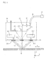
Eine schematisierte Darstellung einer ersten Ausführungsform einer erfindungsgemäßen, gitterbasierten Positionsmesseinrichtung (Encoder) ist in
Die dargestellte Positionsmesseinrichtung umfasst eine Maßverkörperung 10, eine mindestens relativ in Messrichtung x bewegliche Abtasteinheit 20 sowie eine entfernt von der Abtasteinheit 20 angeordnete Lichtquelle 21. Die Maßverkörperung 10 und die Abtasteinheit 20 sind mit zwei - nicht dargestellten - Objekten verbunden, deren Position zueinander erfasst werden soll; beispielsweise handelt es sich hierbei wie eingangs erläutert um relativ zueinander bewegliche Komponenten einer Einrichtung zur Fertigung von Halbleiter-Bauelementen.The illustrated position measuring device comprises a
Die Maßverkörperung 10 ist im vorliegenden Beispiel als lineare Reflexions-Maßverkörperung ausgebildet und besteht aus alternierend in Messrichtung x angeordneten Bereichen unterschiedlicher Reflektivität.The
Die abtastseitigen Elemente zur Erzeugung verschiebungsabhängiger Positionssignale seien nachfolgend auch als Abtastmittel bezeichnet. Neben der Lichtquelle 21 umfassen diese noch verschiedene weitere optische und/oder opto-elektronische Bauelemente. Diese Bauelemente können z.B. in der Abtasteinheit 20 angeordnet sein und/oder aber in einer geeigneten Wirkverbindung mit derselben stehen, z.B. über geeignete Lichtwellenleiter etc.. Zur Erläuterung der Funktionalität der Abtastmittel sei nachfolgend der Abtaststrahlengang des dargestellten Ausführungsbeispiels in
Im Beispiel der
Alternativ zur dargestellten Anordnung der Detektorelemente 27.1 - 27.3 in der Abtasteinheit 10 ist es möglich, diese ähnlich wie die Lichtquelle 21 räumlich getrennt von derselben anzuordnen und die zu detektierenden Teilstrahlenbündel den Detektorelementen über Lichtwellenleiter zuzuführen.As an alternative to the illustrated arrangement of the detector elements 27.1 - 27.3 in the
Im vorliegenden Ausführungsbeispiel der erfindungsgemäßen Positionsmesseinrichtung durchlaufen die Teilstrahlenbündel zwischen der ersten und zweiten Reflexion auf der Maßverkörperung 10 nunmehr deutlich unterschiedliche optische Weglängen L1 und L2, d.h. L1 ≠ L2; dies ist lediglich grob schematisiert in
Bevor anhand der
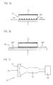
Gezeigt ist in
Die dargestellte zweite Ausführungsform der Positionsmesseinrichtung gestattet im Unterschied zur Variante aus
Zu diesem Zweck umfasst die Abtasteinheit 200 wie in
Der eingangsseitig gelieferte Lichtpuls einer separat von der Abtasteinheit 200 angeordneten Lichtquelle 201 wird über Lichtwellenleiter 208 der Abtasteinheit 200 zugeführt und über eine Aufspaltoptik 202 auf die beiden Abtaststrahlengänge aufgeteilt; auf die Darstellung von Details in den beiden Abtaststrahlengängen wurde aus Gründen der Übersichtlichkeit verzichtet. Die zu den Abtastmitteln zählenden optischen Bauteile sind in
In Bezug auf Details der Abtaststrahlengänge sei an dieser Stelle auch ausdrücklich auf die
Auch in der zweiten Ausführungsform der erfindungsgemäßen Positionsmesseinrichtung wird eine speziell gewählte Lichtquelle eingesetzt, die besondere Vorteile für Hochpräzisionsmessungen bietet.Also in the second embodiment of the position measuring device according to the invention, a specially selected light source is used, which offers particular advantages for high-precision measurements.
So ist die Lichtquelle als Halbleiterlaser mit einer großen Kohärenzlänge ausgebildet, der gepulst in einem Single-Mode-Betrieb arbeitet bzw. betrieben wird. Die Kohärenzlänge liegt hierbei vorzugsweise im Bereich zwischen 1 mm und 1 cm. Es kann damit auch im Fall stark asymmetrischer Teil-Abtaststrahlengänge wie in den beiden oben erläuterten Abtastvarianten eine Interferenz der beiden Teilstrahlenbündel sichergestellt werden, die nach der erfolgten zweiten Beugung und Vereinigung an der Maßverkörperung parallel in Richtung der Detektorelemente propagieren.Thus, the light source is formed as a semiconductor laser with a large coherence length, which operates pulsed in a single-mode operation or operated. The coherence length is preferably in the range between 1 mm and 1 cm. It can thus also in the case of highly asymmetric partial scanning beam paths as in the two above-mentioned scanning a Interference of the two partial beams are ensured, which propagate in the direction of the detector elements after the second diffraction and union on the material measure parallel.
Ferner kann es die jeweilige Messaufgabe erfordern, ein gepulstes Abtastverfahren einzusetzen, wie es z.B. grundsätzlich aus der
Der als Lichtquelle vorgesehene Halbleiterlaser muss hierzu also auch gepulst betreibbar sein, wobei Pulsdauern im Bereich zwischen 5ns und 50ns möglich sein müssen. Im Fall der Verwendung herkömmlicher, gepulst betreibbarer Halbleiterlaser bzw. Laserdioden (z.B Fabry-Perot-Laserdioden), wie etwa in der
Die nunmehr erfindungsgemäß gewählten Lichtquellen in Form der Halbleiterlaser mit hinreichend großer Kohärenzlänge, die zudem gepulst im Single-Mode-Betrieb arbeiten, umgehen diese Probleme. Typische Halbleiterlaser, die diesen Anforderungen genügen, sind etwa sog. DFB-Halbleiterlaser [DFB = Distributed Feedback], DBR-Halbleiterlaser [DBR = Distributed Bragg Reflector] oder aber modengekoppelte Halbleiter- bzw. Festkörperlaser.The light sources selected according to the invention in the form of semiconductor lasers with a sufficiently long coherence length, which also operate pulsed in single-mode operation, circumvent these problems. Typical semiconductor lasers which meet these requirements are, for example, so-called DFB semiconductor lasers [DFB = Distributed Feedback], DBR semiconductor lasers [DBR = Distributed Bragg Reflector] or else mode-locked semiconductor or solid-state lasers.
Die DFB- und die DBR-Halbleiterlaser unterscheiden sich hierbei durch eine zusätzliche Filterstruktur innerhalb des Lasers von herkömmlichen Fabry-Perot-Halbleiterlasern. Diese Filterstruktur führt im dynamischen Betrieb dazu, dass bereits nach sehr kurzer Zeit (ca. 14ps bei DFB-Halbleiterlasern) eine einzige Lasermode herausbildet. Aufgrund dieses sehr schnellen Einschwingvorganges emittiert ein derartiger Halbleiterlaser im Fall von Pulsen im ns-Bereich fast ausschließlich in einer Mode, die eine sehr schmale Bandbreite und somit auch eine hinreichend große Kohärenzlänge für die vorliegende Anwendung besitzt.The DFB and DBR semiconductor lasers differ from conventional Fabry-Perot semiconductor lasers by an additional filter structure within the laser. In dynamic operation, this filter structure leads to the development of a single laser mode after only a very short time (about 14 ps with DFB semiconductor lasers). Because of this very fast transient process In the case of pulses in the ns range, such a semiconductor laser emits almost exclusively in a mode which has a very narrow bandwidth and thus also a sufficiently long coherence length for the present application.
In
Ein Ausführungsbeispiel eines DBR-Halbleiterlasers 61 ist in
Die beiden erwähnten Halbleiterlaser-Varianten können somit dynamisch single-modig betrieben werden und liefern Kohärenzlängen von mehreren Centimetern (DFB-Halbleiterlaser: > 6cm), was sie als bevorzugte Lichtquellen für die erfindungsgemäße Positionsmesseinrichtung geeignet macht.The two mentioned semiconductor laser variants can thus be operated in a single-mode dynamic manner and provide coherence lengths of several centimeters (DFB semiconductor laser:> 6 cm), which makes them suitable as preferred light sources for the position-measuring device according to the invention.
Im Gegensatz zu diesen Halbleiterlaser-Typen schwingen bei einem Fabry-Perot-Halbleiterlaser beim Einschalten des Stroms viele Lasermoden an, aus denen sich dann eine einzige Mode aufgrund von Verstärkungsunterschieden herausbildet. Die typische Zeitkonstante liegt hier bei 10ns - 15ns.In contrast to these types of semiconductor lasers, a Fabry-Perot semiconductor laser, when the power is turned on, oscillates many laser modes, which then form a single mode due to gain differences. The typical time constant is 10ns - 15ns.
Als bereits oben diskutierter Vorteil der relativ großen Kohärenzlängen der erfindungsgemäß gewählten Lichtquellen ist nochmals anzuführen, dass im Unterschied zu Fabry-Perot-Halbleiterlasern mit einer Beschränkung des Gangunterschieds zwischen den zwei interferierenden Teilstrahlen auf weniger als 200µm, nunmehr Abtastprinzipien realisierbar sind, bei denen Teil-abtaststrahlengänge mit Wegunterschieden von bis zu mehreren Centimetern möglich sind.As already discussed above advantage of the relatively large coherence lengths of the light sources chosen according to the invention is again to be stated that in contrast to Fabry-Perot semiconductor lasers with a limitation of the path difference between the two interfering partial beams to less than 200 microns, now sampling principles are feasible, in which partial scanning beam paths with path differences of up to several centimeters are possible.
Dadurch ist man bei der Entwicklung von gepulst betriebenen Positionsmesseinrichtungen nicht mehr auf stark symmetrische Abtaststrahlengänge beschränkt, auch asymmetrische Abtaststrahlengänge sind nun möglich.As a result, it is no longer limited to highly symmetrical scanning beam paths in the development of pulsed-operated position measuring devices, asymmetrical scanning beam paths are now possible.
Zudem kann der größere zulässige Weglängenunterschied für die interferierenden Teilstrahlenbündel für einen erweiterten Toleranzbereich genutzt werden, da durch ein eventuelles Verkippen der von Maßverkörperung und Abtasteinheit der Positionsmesseinrichtung die beiden interferierenden Teilstrahlenbündel ebenfalls unterschiedlich optische Weglängen durchlaufen. Bei Verwendung der oben erwähnten Lichtquellen, bietet sich nun die Möglichkeit beim Einsatz interferentieller Positionsmesseinrichtungen größere Verkippungstoleranzen als bislang üblich zuzulassen.In addition, the larger permissible path length difference for the interfering partial beams can be used for an extended tolerance range, since the two interfering partial beams likewise pass through different optical path lengths due to a possible tilting of the measuring standard and scanning unit of the position measuring device. When using the above-mentioned light sources, now offers the possibility when using interferential position measuring devices greater tipping tolerances than previously allowed.
Als weiterer Vorteil derartiger Lichtquellen wäre anzuführen, dass diese im Pulsbetrieb einen lediglich geringen "Chirp" aufweisen, d.h. einen geringen Frequenzgang über den zeitlichen Pulsverlauf. Bei herkömmlichen, direkt modulierten Halbleiterlasern resultiert üblicherweise eine Frequenzänderung als Funktion der Zeit während des Pulses. Dieser so genannte Chirp hat einen Einfluss auf die oben diskutierte Kohärenzlänge; so nimmt die Kohärenzlänge mit zunehmendem Chirp ab.Another advantage of such light sources would be that they have only a small "chirp" in pulse mode, i. a low frequency response over the temporal pulse progression. Conventional, directly modulated semiconductor lasers usually result in a frequency change as a function of time during the pulse. This so-called chirp has an influence on the coherence length discussed above; so the coherence length decreases with increasing chirp.
Ferner beeinflusst eine derartige Frequenzänderung den Modulationsgrad des resultierenden Positionssignales. Grundsätzlich nimmt der Modulationsgrad des Positionssignales mit wachsendem Chirp ab. Der Einsatz eines gepulst-betriebenen DFB-Halbleiterlasers bzw. DBR-Halbleiterlasers oder eines modengekoppelten Lasers verbessert also auch das Positionssignal im Vergleich zur Verwendung von Fabry-Perot-Halbleiterlasern als Lichtquellen.Furthermore, such a frequency change affects the degree of modulation of the resulting position signal. Basically, the degree of modulation decreases of the position signal with increasing chirp. The use of a pulsed-powered DFB semiconductor laser or DBR semiconductor laser or a mode-locked laser thus also improves the position signal compared to the use of Fabry-Perot semiconductor lasers as light sources.
Im Zusammenhang mit den diskutierten Lichtquellen sei zudem erwähnt, dass dieselben auch in anderen Applikationen bzw. anderen Positionsmesseinrichtungen vorteilhaft zum Einsatz kommen können.In connection with the light sources discussed, it should also be mentioned that they can also be used advantageously in other applications or other position-measuring devices.
Insbesondere im Fall von Positionsmesseinrichtungen mit asymmetrischen Teil-Abtaststrahlengängen ergibt sich im Hinblick auf die verwendete Lichtquelle bzw. die von dieser gelieferte Strahlung ein weiteres Problem. So ist das erzeugte Positionssignal auch von der Wellenlänge der verwendeten Strahlung abhängig. Solange eventuelle Wellenlängenschwankungen innerhalb eines vorgegebenen Zeitintervalles nicht zu groß sind, resultieren keine Fehler bei der Positionsbestimmung; im Fall von zu großen Schwankungen der jeweiligen Wellenlänge und den dann ggf. drohenden Fehlmessungen kann aber auch eine Korrektur dieses Einflusses nötig werden. Hierzu kann im einfachsten Fall die aktuelle Wellenlänge zum Messzeitpunkt oder eine von dieser in bekannter Weise abhängende Position oder eine sonstige Messgröße zu Korrekturzwecken verwendet werden. Mit der bekannten Abhängigkeit der gemessenen Position von der gemessenen Wellenlänge kann diese Position ebenfalls auf einfache Weise im Fall einer Wellenlängenänderung korrigiert werden.Particularly in the case of position measuring devices with asymmetrical partial scanning beam paths, another problem arises with regard to the light source used or the radiation delivered by it. Thus, the generated position signal is also dependent on the wavelength of the radiation used. As long as possible wavelength fluctuations within a predetermined time interval are not too large, no errors result in the position determination; However, in the case of excessive fluctuations of the respective wavelength and the then possibly imminent faulty measurements, a correction of this influence may be necessary. For this purpose, in the simplest case, the current wavelength at the time of measurement or a position dependent thereon in a known manner or another measured variable can be used for correction purposes. With the known dependence of the measured position on the measured wavelength, this position can also be easily corrected in the case of a wavelength change.
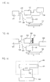
Zur Berücksichtigung von wellenlängenabhängigen Effekten ist demnach grundsätzlich eine Wellenlängenerfassung über geeignete Mittel auf Seiten der verwendeten Positionsmesseinrichtung vorteilhaft, um die daraus resultierenden Informationen zu Korrekturzwecken weiterzuverwerten. Geeignete Möglichkeiten zur Kompensation von wellenlängenbedingten Fehlern bei der Positionsmessung seien nachfolgend anhand der
Die Kontrolle bzw. Erfassung der Wellenlänge kann in einer ersten Variante etwa über ein Wellenlängenmessgerät in Form eines sog. Wavemeter oder Etalons hoher Auflösung erfolgen; hierzu sei auf das Beispiel in
Mit einem entsprechenden Metrologie-Modell der Positionsmesseinrichtung lassen sich eventuelle Positionsabweichungen aufgrund von Wellenlängenänderungen über die nachfolgende Positionssignalverarbeitung in der Auswerteeinheit 450 korrigieren. Unter einem Metrologie-Modell einer Positionsmesseinrichtung wird grds. eine Funktion, z.B. ein Polynom, verstanden, die den Einfluss von Bewegungstoleranzen (Kippungen), Fertigungstoleranzen (Keilwinkel etc.) und Wellenlänge auf die erzeugte Positionsinformation beschreibt.With a corresponding metrology model of the position measuring device, any position deviations due to wavelength changes can be corrected via the subsequent position signal processing in the
Eine alternative, zweite Variante zur Messung der Wellenlänge ist die Verwendung einer zusätzlichen Positionsmesseinrichtung, wie sie auch zur eigentlichen Positionsbestimmung verwendet wird; hierzu sei auf die
In einer dritten Variante, zu der
Im Rahmen der vorliegenden Erfindung gibt es neben den erläuterten Beispielen selbstverständlich eine Reihe weiterer Ausführungsmöglichkeiten.In the context of the present invention, of course, there are a number of other possible embodiments in addition to the illustrated examples.
Claims (17)
- Position measuring device for detecting the position of two objects which are arranged movably relative to one another in at least one measurement direction (x; z), the position measuring device comprising a material measure (10; 100; 410; 510; 610) and scanning means with a light source (21; 201; 51; 61; 71; 421; 521; 621) and one or more optical and/or optoelectronic components for generating displacement-dependent position signals, and the light source (21; 201; 51; 61; 71; 421; 521; 621) being designed as a semiconductor laser, characterized in that the semiconductor laser has a coherence length of greater than 200 µm and operates by pulsing in single-mode operation.
- Position measuring device according to Claim 1, characterized in that the semiconductor laser supplies light pulses with pulse durations in the range from 5 ns to 50 ns.
- Position measuring device according to at least one of Claims 1-2, characterized in that the light source (21; 201; 51; 421; 521; 621) is designed as a DFB semiconductor laser.
- Position measuring device according to at least one of Claims 1-2, characterized in that the light source is designed as a DBR semiconductor laser (21; 201; 61; 421; 521; 621).
- Position measuring device according to at least one of Claims 1-2, characterized in that the light source (21; 201; 71; 421; 521; 621) is designed as a mode-locked semiconductor laser or mode-locked solid-state laser.
- Position measuring device according to at least one of the preceding claims, characterized in that via the arrangement of the scanning means asymmetric partial scanning beam paths with different optical path lengths are formed which are traversed by partial beams before the partial beams come to interfere by super-position.
- Position measuring device according to at least one of the preceding claims, characterized in that the scanning means are arranged in a scanning unit (20; 200; 420; 520) which is movable relative to the material measure (10; 100; 410; 510; 610), and the light source (21; 201; 51; 61; 71; 421; 521; 621) is arranged remote from the scanning unit (20; 200; 420; 520), the light source (21; 201; 51; 61; 71; 421; 521; 621) being connected to the scanning unit (20; 200; 420; 520) by means of an optical fibre (28; 208; 428; 528).
- Position measuring device according to Claim 1, characterized in that said device is assigned means for determining the wavelength of the radiation used for optical position determination.
- Position measuring device according to Claim 8, characterized in that the means for determining the wavelength are designed as a wavelength meter (430) whose measured values are fed to an evaluation unit (450) which undertakes a correction of the wavelength-dependent position error in conjunction with a metrology model of the position measuring device.
- Position measuring device according to Claim 8, characterized in that the means for determining the wavelength are designed as an additional position measuring device (530) which comprises a scanning unit (532) and a material measure (531) in a fixed spatial assignment, and whose measured values are fed to an evaluation unit (550) which thereby undertakes a correction of the wavelength-dependent position errors.
- Position measuring device according to Claim 8, characterized in that the means for determining the wavelength include temperature detecting means (622) via which the temperature of the light source (621) is determined and the detected temperature is fed to an evaluation unit (650) which thereby undertakes a correction of wavelength-dependent position errors given a known dependence of the wavelength on the temperature.
- Method for operating a position measuring device for detecting the position of two objects which are arranged movably relative to one another in at least one measurement direction (x; z), the position measuring device comprising a material measure (10; 100; 410; 510; 610) and scanning means with a light source (21; 201; 51; 61; 71; 421; 521; 621) and one or more optical and/or optoelectronic components for generating displacement-dependent position signals, and the light source (21; 201; 51; 61; 71; 421; 521; 621) being designed as a semiconductor laser, characterized in that the semiconductor laser has a coherence length of greater than 200 µm and is operated by pulsing in single-mode operation.
- Method according to Claim 12, characterized in that the semiconductor laser is operated by pulsing in such a way that it supplies light pulses with pulse durations in the range from 5 ns to 50 ns.
- Method according to Claim 12, characterized in that in addition the wavelength of the radiation used for optical position determination is determined.
- Method according to Claim 14, characterized in that the wavelength is determined by using a wavelength meter (430) whose measured values are fed to an evaluation unit (450) by means of which a correction of the wavelength-dependent position errors is undertaken in conjunction with a metrology model of the position measuring device.
- Method according to Claim 14, characterized in that in order to determine the wavelength use is made of an additional position measuring device (530) which comprises a scanning unit (532) and a material measure (531) in a fixed spatial assignment, and whose measured values are fed to an evaluation unit (550) by means of which a correction of the wavelength-dependent position errors is undertaken.
- Method according to Claim 14, characterized in that in order to determine the wavelength use is made of temperature detecting means (622) via which the temperature of the light source is determined and the detected temperature is fed to an evaluation unit (650) by means of which a correction of wavelength-dependent position errors is undertaken given a known dependence of the wavelength on the temperature.
Applications Claiming Priority (2)
| Application Number | Priority Date | Filing Date | Title |
|---|---|---|---|
| DE102005053789 | 2005-11-09 | ||
| DE102006041357A DE102006041357A1 (en) | 2005-11-09 | 2006-09-01 | Position measuring device and method for operating a position-measuring device |
Publications (3)
| Publication Number | Publication Date |
|---|---|
| EP1785698A2 EP1785698A2 (en) | 2007-05-16 |
| EP1785698A3 EP1785698A3 (en) | 2010-07-14 |
| EP1785698B1 true EP1785698B1 (en) | 2015-06-17 |
Family
ID=37745911
Family Applications (2)
| Application Number | Title | Priority Date | Filing Date |
|---|---|---|---|
| EP06828910A Active EP1949039B1 (en) | 2005-11-09 | 2006-11-02 | Position measurement system |
| EP06022850.9A Active EP1785698B1 (en) | 2005-11-09 | 2006-11-02 | Position measuring device and method for operating a position measuring device |
Family Applications Before (1)
| Application Number | Title | Priority Date | Filing Date |
|---|---|---|---|
| EP06828910A Active EP1949039B1 (en) | 2005-11-09 | 2006-11-02 | Position measurement system |
Country Status (4)
| Country | Link |
|---|---|
| EP (2) | EP1949039B1 (en) |
| JP (2) | JP5128108B2 (en) |
| DE (1) | DE102006041357A1 (en) |
| WO (1) | WO2007054234A1 (en) |
Families Citing this family (6)
| Publication number | Priority date | Publication date | Assignee | Title |
|---|---|---|---|---|
| US7389595B2 (en) * | 2005-11-09 | 2008-06-24 | Dr. Johannes Heidenhain Gmbh | Position-measuring device and method for operating a position-measuring device |
| DE102008007319A1 (en) * | 2008-02-02 | 2009-08-06 | Dr. Johannes Heidenhain Gmbh | Optical position measuring device |
| DE102009054592A1 (en) * | 2009-12-14 | 2011-06-16 | Dr. Johannes Heidenhain Gmbh | Position measuring device |
| DE102011076178B4 (en) * | 2011-05-20 | 2022-03-31 | Dr. Johannes Heidenhain Gmbh | position measuring device |
| JP6849371B2 (en) | 2015-10-08 | 2021-03-24 | 三星電子株式会社Samsung Electronics Co.,Ltd. | Side emission laser light source and 3D image acquisition device including it |
| CN109752033B (en) * | 2019-02-22 | 2024-01-30 | 上海交通大学 | High-precision fiber bragg grating strain measurement system |
Family Cites Families (14)
| Publication number | Priority date | Publication date | Assignee | Title |
|---|---|---|---|---|
| JPS5918412A (en) * | 1982-07-22 | 1984-01-30 | Fanuc Ltd | Position detecting system |
| ATE221186T1 (en) * | 1997-09-29 | 2002-08-15 | Heidenhain Gmbh Dr Johannes | DEVICE FOR DETECTING THE POSITION OF TWO BODY |
| DE19843176C1 (en) * | 1998-09-21 | 2000-10-19 | Siemens Ag | Optical encoder for the detection of rotary and linear movements |
| JP2000304507A (en) * | 1999-04-21 | 2000-11-02 | Citizen Watch Co Ltd | Dimension measuring device using diffracted light interference of diffraction grating |
| DE19941318A1 (en) * | 1999-08-31 | 2001-03-15 | Heidenhain Gmbh Dr Johannes | Optical position measuring device |
| US6494616B1 (en) * | 2000-08-04 | 2002-12-17 | Regents Of The University Of Minnesota | Multiplexed sensor array |
| WO2002033358A1 (en) * | 2000-10-22 | 2002-04-25 | Stridsberg Innovation Ab | Position transducer |
| DE10054062A1 (en) * | 2000-10-31 | 2002-05-16 | Heidenhain Gmbh Dr Johannes | Position determination method and position measuring device for carrying out the method |
| DE10158223B4 (en) * | 2001-11-16 | 2017-10-05 | Dr. Johannes Heidenhain Gmbh | Rotation angle meter |
| DE10235669B4 (en) * | 2002-08-03 | 2016-11-17 | Dr. Johannes Heidenhain Gmbh | Position measuring device |
| JP4381671B2 (en) * | 2002-10-23 | 2009-12-09 | ソニーマニュファクチュアリングシステムズ株式会社 | Displacement detector |
| DE102004011698B4 (en) * | 2004-03-10 | 2007-12-13 | Siemens Ag | Method for detecting a sensor type |
| DE102004053082A1 (en) * | 2004-11-03 | 2006-05-04 | Dr. Johannes Heidenhain Gmbh | Position measuring system |
| DE102005043569A1 (en) * | 2005-09-12 | 2007-03-22 | Dr. Johannes Heidenhain Gmbh | Position measuring device |
-
2006
- 2006-09-01 DE DE102006041357A patent/DE102006041357A1/en not_active Withdrawn
- 2006-10-30 JP JP2006293620A patent/JP5128108B2/en active Active
- 2006-11-02 JP JP2008539306A patent/JP4999856B2/en active Active
- 2006-11-02 EP EP06828910A patent/EP1949039B1/en active Active
- 2006-11-02 EP EP06022850.9A patent/EP1785698B1/en active Active
- 2006-11-02 WO PCT/EP2006/010525 patent/WO2007054234A1/en active Application Filing
Also Published As
| Publication number | Publication date |
|---|---|
| WO2007054234A1 (en) | 2007-05-18 |
| DE102006041357A1 (en) | 2007-05-10 |
| JP4999856B2 (en) | 2012-08-15 |
| EP1785698A3 (en) | 2010-07-14 |
| EP1949039A1 (en) | 2008-07-30 |
| EP1785698A2 (en) | 2007-05-16 |
| JP5128108B2 (en) | 2013-01-23 |
| EP1949039B1 (en) | 2012-09-12 |
| JP2007132932A (en) | 2007-05-31 |
| JP2009515177A (en) | 2009-04-09 |
Similar Documents
| Publication | Publication Date | Title |
|---|---|---|
| EP2333493B1 (en) | Position measuring device | |
| EP0564431B1 (en) | Device for stabilising the wavelength of a light beam emitted by a laser-diode and laser-interferometer | |
| EP1319170B1 (en) | Position measuring device | |
| EP2149029B1 (en) | Position measuring device | |
| EP1655582B1 (en) | Position measuring system | |
| EP1785698B1 (en) | Position measuring device and method for operating a position measuring device | |
| EP2765394B1 (en) | Optical positioning device | |
| EP1762828A2 (en) | Optical encoder for determining the position of two parts that are movable relative to one another in two directions of movement | |
| EP3447441B1 (en) | Device for interferometric distance measurement | |
| EP1923672A2 (en) | Position measuring device | |
| EP2474815A1 (en) | Optical positioning device | |
| US7389595B2 (en) | Position-measuring device and method for operating a position-measuring device | |
| DE10235669B4 (en) | Position measuring device | |
| AT392537B (en) | INTERFEROMETER ARRANGEMENT, ESPECIALLY FOR DISTANCE OR DETERMINATION OF A MOVING COMPONENT | |
| DE102005023489B4 (en) | Position measuring device for determining the position of two along a measuring direction to each other movable objects and method for forming a reference pulse for such a position measuring device | |
| DE3836703C2 (en) | ||
| EP1068486B1 (en) | Position measuring device | |
| EP2869034B1 (en) | Position sensing device | |
| DE3632922C2 (en) | ||
| EP2356405B1 (en) | Optical position measuring device | |
| DE10013725A1 (en) | Measurement device directs beam to measurement scale and receives reflections of beam to produce phase shifted interference signals which are then evaluated | |
| DE102015209117A1 (en) | Interferential position measuring device and method for operating an interferential position measuring device | |
| WO1989008825A1 (en) | Arrangement for determining wavelength or refractive index |
Legal Events
| Date | Code | Title | Description |
|---|---|---|---|
| PUAI | Public reference made under article 153(3) epc to a published international application that has entered the european phase |
Free format text: ORIGINAL CODE: 0009012 |
|
| AK | Designated contracting states |
Kind code of ref document: A2 Designated state(s): AT BE BG CH CY CZ DE DK EE ES FI FR GB GR HU IE IS IT LI LT LU LV MC NL PL PT RO SE SI SK TR |
|
| AX | Request for extension of the european patent |
Extension state: AL BA HR MK YU |
|
| PUAL | Search report despatched |
Free format text: ORIGINAL CODE: 0009013 |
|
| AK | Designated contracting states |
Kind code of ref document: A3 Designated state(s): AT BE BG CH CY CZ DE DK EE ES FI FR GB GR HU IE IS IT LI LT LU LV MC NL PL PT RO SE SI SK TR |
|
| AX | Request for extension of the european patent |
Extension state: AL BA HR MK RS |
|
| RIC1 | Information provided on ipc code assigned before grant |
Ipc: G01D 5/347 20060101AFI20100604BHEP |
|
| 17P | Request for examination filed |
Effective date: 20110114 |
|
| AKX | Designation fees paid |
Designated state(s): AT BE BG CH CY CZ DE DK EE ES FI FR GB GR HU IE IS IT LI LT LU LV MC NL PL PT RO SE SI SK TR |
|
| GRAP | Despatch of communication of intention to grant a patent |
Free format text: ORIGINAL CODE: EPIDOSNIGR1 |
|
| INTG | Intention to grant announced |
Effective date: 20150407 |
|
| GRAS | Grant fee paid |
Free format text: ORIGINAL CODE: EPIDOSNIGR3 |
|
| GRAA | (expected) grant |
Free format text: ORIGINAL CODE: 0009210 |
|
| AK | Designated contracting states |
Kind code of ref document: B1 Designated state(s): AT BE BG CH CY CZ DE DK EE ES FI FR GB GR HU IE IS IT LI LT LU LV MC NL PL PT RO SE SI SK TR |
|
| REG | Reference to a national code |
Ref country code: GB Ref legal event code: FG4D Free format text: NOT ENGLISH |
|
| REG | Reference to a national code |
Ref country code: CH Ref legal event code: EP |
|
| REG | Reference to a national code |
Ref country code: AT Ref legal event code: REF Ref document number: 732191 Country of ref document: AT Kind code of ref document: T Effective date: 20150715 |
|
| REG | Reference to a national code |
Ref country code: IE Ref legal event code: FG4D Free format text: LANGUAGE OF EP DOCUMENT: GERMAN |
|
| REG | Reference to a national code |
Ref country code: DE Ref legal event code: R096 Ref document number: 502006014380 Country of ref document: DE |
|
| REG | Reference to a national code |
Ref country code: NL Ref legal event code: T3 |
|
| PG25 | Lapsed in a contracting state [announced via postgrant information from national office to epo] |
Ref country code: FI Free format text: LAPSE BECAUSE OF FAILURE TO SUBMIT A TRANSLATION OF THE DESCRIPTION OR TO PAY THE FEE WITHIN THE PRESCRIBED TIME-LIMIT Effective date: 20150617 Ref country code: LT Free format text: LAPSE BECAUSE OF FAILURE TO SUBMIT A TRANSLATION OF THE DESCRIPTION OR TO PAY THE FEE WITHIN THE PRESCRIBED TIME-LIMIT Effective date: 20150617 |
|
| REG | Reference to a national code |
Ref country code: LT Ref legal event code: MG4D |
|
| PG25 | Lapsed in a contracting state [announced via postgrant information from national office to epo] |
Ref country code: LV Free format text: LAPSE BECAUSE OF FAILURE TO SUBMIT A TRANSLATION OF THE DESCRIPTION OR TO PAY THE FEE WITHIN THE PRESCRIBED TIME-LIMIT Effective date: 20150617 Ref country code: GR Free format text: LAPSE BECAUSE OF FAILURE TO SUBMIT A TRANSLATION OF THE DESCRIPTION OR TO PAY THE FEE WITHIN THE PRESCRIBED TIME-LIMIT Effective date: 20150918 Ref country code: BG Free format text: LAPSE BECAUSE OF FAILURE TO SUBMIT A TRANSLATION OF THE DESCRIPTION OR TO PAY THE FEE WITHIN THE PRESCRIBED TIME-LIMIT Effective date: 20150917 |
|
| PG25 | Lapsed in a contracting state [announced via postgrant information from national office to epo] |
Ref country code: EE Free format text: LAPSE BECAUSE OF FAILURE TO SUBMIT A TRANSLATION OF THE DESCRIPTION OR TO PAY THE FEE WITHIN THE PRESCRIBED TIME-LIMIT Effective date: 20150617 |
|
| PG25 | Lapsed in a contracting state [announced via postgrant information from national office to epo] |
Ref country code: RO Free format text: LAPSE BECAUSE OF NON-PAYMENT OF DUE FEES Effective date: 20150617 Ref country code: IS Free format text: LAPSE BECAUSE OF FAILURE TO SUBMIT A TRANSLATION OF THE DESCRIPTION OR TO PAY THE FEE WITHIN THE PRESCRIBED TIME-LIMIT Effective date: 20151017 Ref country code: PL Free format text: LAPSE BECAUSE OF FAILURE TO SUBMIT A TRANSLATION OF THE DESCRIPTION OR TO PAY THE FEE WITHIN THE PRESCRIBED TIME-LIMIT Effective date: 20150617 Ref country code: ES Free format text: LAPSE BECAUSE OF FAILURE TO SUBMIT A TRANSLATION OF THE DESCRIPTION OR TO PAY THE FEE WITHIN THE PRESCRIBED TIME-LIMIT Effective date: 20150617 Ref country code: CZ Free format text: LAPSE BECAUSE OF FAILURE TO SUBMIT A TRANSLATION OF THE DESCRIPTION OR TO PAY THE FEE WITHIN THE PRESCRIBED TIME-LIMIT Effective date: 20150617 Ref country code: PT Free format text: LAPSE BECAUSE OF FAILURE TO SUBMIT A TRANSLATION OF THE DESCRIPTION OR TO PAY THE FEE WITHIN THE PRESCRIBED TIME-LIMIT Effective date: 20151019 Ref country code: SK Free format text: LAPSE BECAUSE OF FAILURE TO SUBMIT A TRANSLATION OF THE DESCRIPTION OR TO PAY THE FEE WITHIN THE PRESCRIBED TIME-LIMIT Effective date: 20150617 |
|
| REG | Reference to a national code |
Ref country code: DE Ref legal event code: R097 Ref document number: 502006014380 Country of ref document: DE |
|
| PLBE | No opposition filed within time limit |
Free format text: ORIGINAL CODE: 0009261 |
|
| STAA | Information on the status of an ep patent application or granted ep patent |
Free format text: STATUS: NO OPPOSITION FILED WITHIN TIME LIMIT |
|
| PG25 | Lapsed in a contracting state [announced via postgrant information from national office to epo] |
Ref country code: DK Free format text: LAPSE BECAUSE OF FAILURE TO SUBMIT A TRANSLATION OF THE DESCRIPTION OR TO PAY THE FEE WITHIN THE PRESCRIBED TIME-LIMIT Effective date: 20150617 Ref country code: IT Free format text: LAPSE BECAUSE OF FAILURE TO SUBMIT A TRANSLATION OF THE DESCRIPTION OR TO PAY THE FEE WITHIN THE PRESCRIBED TIME-LIMIT Effective date: 20150617 |
|
| 26N | No opposition filed |
Effective date: 20160318 |
|
| PG25 | Lapsed in a contracting state [announced via postgrant information from national office to epo] |
Ref country code: MC Free format text: LAPSE BECAUSE OF FAILURE TO SUBMIT A TRANSLATION OF THE DESCRIPTION OR TO PAY THE FEE WITHIN THE PRESCRIBED TIME-LIMIT Effective date: 20150617 Ref country code: LU Free format text: LAPSE BECAUSE OF FAILURE TO SUBMIT A TRANSLATION OF THE DESCRIPTION OR TO PAY THE FEE WITHIN THE PRESCRIBED TIME-LIMIT Effective date: 20151102 |
|
| REG | Reference to a national code |
Ref country code: CH Ref legal event code: PL |
|
| PG25 | Lapsed in a contracting state [announced via postgrant information from national office to epo] |
Ref country code: LI Free format text: LAPSE BECAUSE OF NON-PAYMENT OF DUE FEES Effective date: 20151130 Ref country code: CH Free format text: LAPSE BECAUSE OF NON-PAYMENT OF DUE FEES Effective date: 20151130 |
|
| REG | Reference to a national code |
Ref country code: IE Ref legal event code: MM4A |
|
| REG | Reference to a national code |
Ref country code: FR Ref legal event code: ST Effective date: 20160729 |
|
| PG25 | Lapsed in a contracting state [announced via postgrant information from national office to epo] |
Ref country code: SI Free format text: LAPSE BECAUSE OF FAILURE TO SUBMIT A TRANSLATION OF THE DESCRIPTION OR TO PAY THE FEE WITHIN THE PRESCRIBED TIME-LIMIT Effective date: 20150617 |
|
| PG25 | Lapsed in a contracting state [announced via postgrant information from national office to epo] |
Ref country code: IE Free format text: LAPSE BECAUSE OF NON-PAYMENT OF DUE FEES Effective date: 20151102 |
|
| PG25 | Lapsed in a contracting state [announced via postgrant information from national office to epo] |
Ref country code: FR Free format text: LAPSE BECAUSE OF NON-PAYMENT OF DUE FEES Effective date: 20151130 |
|
| REG | Reference to a national code |
Ref country code: AT Ref legal event code: MM01 Ref document number: 732191 Country of ref document: AT Kind code of ref document: T Effective date: 20151102 |
|
| PG25 | Lapsed in a contracting state [announced via postgrant information from national office to epo] |
Ref country code: AT Free format text: LAPSE BECAUSE OF NON-PAYMENT OF DUE FEES Effective date: 20151102 |
|
| PG25 | Lapsed in a contracting state [announced via postgrant information from national office to epo] |
Ref country code: HU Free format text: LAPSE BECAUSE OF FAILURE TO SUBMIT A TRANSLATION OF THE DESCRIPTION OR TO PAY THE FEE WITHIN THE PRESCRIBED TIME-LIMIT; INVALID AB INITIO Effective date: 20061102 |
|
| PG25 | Lapsed in a contracting state [announced via postgrant information from national office to epo] |
Ref country code: CY Free format text: LAPSE BECAUSE OF FAILURE TO SUBMIT A TRANSLATION OF THE DESCRIPTION OR TO PAY THE FEE WITHIN THE PRESCRIBED TIME-LIMIT Effective date: 20150617 Ref country code: SE Free format text: LAPSE BECAUSE OF FAILURE TO SUBMIT A TRANSLATION OF THE DESCRIPTION OR TO PAY THE FEE WITHIN THE PRESCRIBED TIME-LIMIT Effective date: 20150617 |
|
| PG25 | Lapsed in a contracting state [announced via postgrant information from national office to epo] |
Ref country code: BE Free format text: LAPSE BECAUSE OF NON-PAYMENT OF DUE FEES Effective date: 20151130 |
|
| PG25 | Lapsed in a contracting state [announced via postgrant information from national office to epo] |
Ref country code: TR Free format text: LAPSE BECAUSE OF FAILURE TO SUBMIT A TRANSLATION OF THE DESCRIPTION OR TO PAY THE FEE WITHIN THE PRESCRIBED TIME-LIMIT Effective date: 20150617 |
|
| PGFP | Annual fee paid to national office [announced via postgrant information from national office to epo] |
Ref country code: NL Payment date: 20231120 Year of fee payment: 18 |
|
| PGFP | Annual fee paid to national office [announced via postgrant information from national office to epo] |
Ref country code: GB Payment date: 20231123 Year of fee payment: 18 |
|
| PGFP | Annual fee paid to national office [announced via postgrant information from national office to epo] |
Ref country code: DE Payment date: 20231121 Year of fee payment: 18 |