EP1784068B1 - Flat display device and cooling apparatus for the same - Google Patents
Flat display device and cooling apparatus for the same Download PDFInfo
- Publication number
- EP1784068B1 EP1784068B1 EP06254245.1A EP06254245A EP1784068B1 EP 1784068 B1 EP1784068 B1 EP 1784068B1 EP 06254245 A EP06254245 A EP 06254245A EP 1784068 B1 EP1784068 B1 EP 1784068B1
- Authority
- EP
- European Patent Office
- Prior art keywords
- flat display
- back cover
- display device
- cross
- flow fan
- Prior art date
- Legal status (The legal status is an assumption and is not a legal conclusion. Google has not performed a legal analysis and makes no representation as to the accuracy of the status listed.)
- Not-in-force
Links
Images


Classifications
-
- H—ELECTRICITY
- H01—ELECTRIC ELEMENTS
- H01J—ELECTRIC DISCHARGE TUBES OR DISCHARGE LAMPS
- H01J17/00—Gas-filled discharge tubes with solid cathode
- H01J17/02—Details
- H01J17/28—Cooling arrangements
-
- H—ELECTRICITY
- H05—ELECTRIC TECHNIQUES NOT OTHERWISE PROVIDED FOR
- H05K—PRINTED CIRCUITS; CASINGS OR CONSTRUCTIONAL DETAILS OF ELECTRIC APPARATUS; MANUFACTURE OF ASSEMBLAGES OF ELECTRICAL COMPONENTS
- H05K7/00—Constructional details common to different types of electric apparatus
- H05K7/20—Modifications to facilitate cooling, ventilating, or heating
- H05K7/20954—Modifications to facilitate cooling, ventilating, or heating for display panels
- H05K7/20972—Forced ventilation, e.g. on heat dissipaters coupled to components
-
- H—ELECTRICITY
- H01—ELECTRIC ELEMENTS
- H01J—ELECTRIC DISCHARGE TUBES OR DISCHARGE LAMPS
- H01J11/00—Gas-filled discharge tubes with alternating current induction of the discharge, e.g. alternating current plasma display panels [AC-PDP]; Gas-filled discharge tubes without any main electrode inside the vessel; Gas-filled discharge tubes with at least one main electrode outside the vessel
- H01J11/20—Constructional details
- H01J11/34—Vessels, containers or parts thereof, e.g. substrates
-
- Y—GENERAL TAGGING OF NEW TECHNOLOGICAL DEVELOPMENTS; GENERAL TAGGING OF CROSS-SECTIONAL TECHNOLOGIES SPANNING OVER SEVERAL SECTIONS OF THE IPC; TECHNICAL SUBJECTS COVERED BY FORMER USPC CROSS-REFERENCE ART COLLECTIONS [XRACs] AND DIGESTS
- Y10—TECHNICAL SUBJECTS COVERED BY FORMER USPC
- Y10S—TECHNICAL SUBJECTS COVERED BY FORMER USPC CROSS-REFERENCE ART COLLECTIONS [XRACs] AND DIGESTS
- Y10S345/00—Computer graphics processing and selective visual display systems
- Y10S345/905—Display device with housing structure
Landscapes
- Physics & Mathematics (AREA)
- Engineering & Computer Science (AREA)
- Thermal Sciences (AREA)
- Microelectronics & Electronic Packaging (AREA)
- Plasma & Fusion (AREA)
- Devices For Indicating Variable Information By Combining Individual Elements (AREA)
- Cooling Or The Like Of Electrical Apparatus (AREA)
Description
- The present invention relates to a flat display device. The present invention also relates to a cooling apparatus for a flat display device. The cooling device for a flat panel display device can be operated with a low noise while quickly dissipating a large amount of internal heat to the surroundings by improving an installation structure of a fan.
- Unlike a cathode ray tube (CRT), a flat display uses a driving circuit arranged in a matrix pattern to differently excite pixels and thus realize an image. Recently, the flat display device has been widely used as it has advantage in that it takes up a relatively small space. A variety of flat display modules such as a liquid crystal display (LCD), a field emission display (FED), a plasma display panel (PDP), and an electroluminescence (EL) have been applied to the flat display device.
- The flat display device using the flat display module is reduced in thickness as compared with the CRT. However, since a large number of heat-generating components must be incorporated in a narrow space of the display device, the heat, which is generated by the heat-generating components in the flat display device during the operation of the flat display module, must be effectively dissipated to the surroundings.
- Particularly, in the case of the PDP, since the image is realized by electric discharge of discharge gas, high temperature heat is generated. Therefore, if the high temperature heat is not quickly dissipated, the display device may malfunction. Needless to say, in the case of other types of flat display devices, the heat dissipation performance is very important fact determining the quality thereof.
- In order to locally dissipate the heat, a heat sink is attached on a rear surface of a specific component generating a large amount of heat to cool the specific component. Furthermore, in order to generally dissipate the heat, a plurality of holes are formed on a cover of the flat display device so that cool air can pass through the holes. However, although the cooling effect for the specific component may be expected, the heat is not effectively dissipated to the surroundings. Therefore, the flat display device cannot be stably operated. That is, the internal temperature of the flat display device increases to deteriorate the performance of the flat display device.
- In order to solve the above problem, an axial fan is installed on a rear center of a back cover in a direction perpendicular to a direction where the display device is formed. The axial fan forcedly exhausts the internal high temperature air of the flat display device to the surroundings through a rear side of the display device. In this case, although the heat collected in the display device can be effectively discharged to the surroundings, excessive noise is generated during the operation of the axial fan. Furthermore, a gap of ten or more centimeters must be provided between the rear surface of the display device and the wall so that the air can be exhausted. In addition, due to a gap between the axial fan and the flat display module and a thickness of the axial fan, an overall thickness of the flat display device increases.
- Furthermore, a plurality of holes through which the air is exhausted and introduced are formed on the back cover. The holes of the back cover deteriorate strength of the back cover. Therefore, the back cover must be made thick. In this case, the manufacturing cost increases.
- The present invention has been made in view of the above-mentioned problems.
- Embodiments of the present invention can provide a cooling apparatus for a flat display device, which is designed to make the flat display device slimmer and effectively dissipate internal heat of the flat display device.
- Embodiments of the present invention can also provide a cooling apparatus for a flat display device, which can minimize noise and be manufactured with low costs.
- Embodiments of the present invention can further provide a cooling apparatus for a flat display device, which can minimize noise and improve heat dissipation efficiency by allowing internal air of the flat display device to be exhausted by natural convection.
- Embodiments of the present invention can provide a cooling apparatus for a flat display device, which can improve an operation reliability of the flat display device by stably supporting a cooling fan.
- Additional advantages and features of the invention will be set forth in part in the description which follows and in part will become apparent to those having ordinary skill in the art upon examination of the following or may be learned from practice of the invention. The advantages of the invention may be realized and attained by the structure particularly pointed out in the written description and claims hereof as well as the appended drawings.
- In an aspect of the present invention, there is provided a flat display device, comprising: a flat display module; front and back covers defining a space for receiving the flat display module and protecting components disposed in the space, such that there is gap between a heat generating component provided on a surface of the flat display module and an inner surface of the back cover allowing air to flow through the gap to cool the heat generating component; an air inlet(16) formed on a portion of the back cover along the overall longitudinal length of the lower periphery of the back cover; an air outlet formed on an upper peripheral portion of the back cover that is inclined toward a center of the flat display module as it goes rearward, such that it can be hidden when the flat display device is viewed from a front side; a cross-flow fan disposed between an upper portion of the back cover and an upper portion of the front cover, along the overall longitudinal length of the top surface of the back cover, wherein the cross-flow fan(7) includes an impeller(10) disposed in the longitudinal direction of the back cover(4), wherein the effective exhaust area of the air outlet channel of the cross-flow fan is formed throughout the overall area of the top surface of the back cover (4)..
- In embodiments of the present invention, the heat dissipation efficiency can be improved and the vibration and noise caused by airflow can be reduced.
- It is to be understood that both the foregoing general description and the following detailed description of the present invention are exemplary and explanatory and are intended to provide further explanation of the invention as claimed.
- Embodiments of the invention will now be described by way of non-limiting example only, with reference to the drawings, in which:
-
FIG. 1 is a perspective view of a flat display device according to an embodiment of the present invention; -
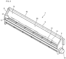
FIG. 2 is an exploded perspective view of the flat display device ofFIG. 1 ; -
FIG. 3 is a rear perspective view of a cross-flow fan according to an embodiment of the present invention; -
FIG. 4 is a sectional view taken along line I-I' ofFIG. 1 ; and -
FIG. 5 is a rear view of the flat display device ofFIG. 1 . - Reference will now be made in detail to the preferred embodiments of the present invention, examples of which are illustrated in the accompanying drawings. Where appropriate, the same reference numbers will be used throughout the drawings to refer to the same or like parts.
- Referring to
FIG. 1 , aflat display device 1 of this embodiment includes aflat display module 2, afront cover 3 for supporting and protecting a front portion of theflat display module 2, and aback cover 4 for supporting and protecting a rear portion of theflat display module 2. Anupper air outlet 5 through which internal hot air of theflat display device 1 exhaust is formed on an upper inclined periphery of theback cover 4. - The
flat display module 2 may be selected from the group consisting of an LCD, an FED, a PDP, and an EL. Theflat display module 2 may be a PDP generating a large amount of heat. - The front and back covers 3 and 4 define a space for receiving the
flat display module 2 and protect components disposed in the space. The front and back covers 3 and 4 are independent parts that are assembled with each other. However, the embodiments of the present invention are not limited to this case. For example, the front andrear covers flat display module 2 and an inner surface of theback cover 4 so that air flows through the gap to cool the heat generating component and is then exhausted through theupper air outlet 5. - The operation of a cooling apparatus of the present invention will now be described with reference to the above flat display device.
- When the
flat display device 1 operates, a large amount of heat is generated in theflat display module 2. The hot air generated from the heat generating component disposed on the rear surface of theflat display module 2 is cooled by the incoming air. The hot air flows upward and is exhausted through theupper air outlet 5. This is the natural convection for exhausting the hot air out of the flat display device, thereby improving the cooling efficiency. The external air is introduced through an overall area of the lower peripheral portion of theflat display device 1 and exhausted via an overall area of the rear portion of thedisplay device 1. - Furthermore, the
upper air outlet 5 is provided on an inclined peripheral portion of the back cover so that the hot air can be exhausted upward and thus the hot air can more effectively flow. - In addition, since the front surface of the
flat display module 2 is exposed to the surroundings, the heat generated from the front portion of thedisplay module 2 can be quickly dissipated by the natural convection of the outer air. -
FIG. 2 is an exploded perspective view of the flat display device, in which thedisplay module 2 and the front cover are in an assembled state. - Referring to
FIGs. 1 and2 , thecross-flow fan 7 is disposed between an upper portion of theback cover 4 and an upper portion of thefront cover 3. Anair outlet channel 20 of thecross-flow fan 7 is aligned with theupper air outlet 5 of theback cover 4. Therefore, when the cross-flow fan operates, the internal hot air of the flat display device can be exhausted to the surroundings through theupper air outlet 5 of theback cover 4. - The peripheral portion of the
back cover 4 is inclined toward a center of the display device as it goes rearward, thereby defining aninclined surface 8. As the peripheral portion of theback cover 4 is inclined, it can be hidden when the flat display device is viewed from a front side, thereby not deteriorating the appearance of the display device. In addition, the inclination of the peripheral portion of theback cover 4 makes the flat display device compact. A plurality of slits is formed on the topinclined surface 8 of the peripheral portion of theback cover 4 to define theair outlet 5. - Referring to
FIG. 3 , thecross-flow fan 7 includes animpeller 10 disposed in the longitudinal direction of theback cover 4 and acircular plate 11 for dividing theimpeller 10 by a predetermined interval along the longitudinal direction of theimpeller 10 and enhancing strength of theimpeller 10. Thecross-flow fan 7 is further includes a driving shaft (not shown) connected to amotor 14. A rotational force of themotor 14 is transferred to the cross-flow fan via the driving shaft. - The
impeller 10 is disposed in ahousing 18 to guide the airflow when theimpeller 10 rotates. Thehousing 18 includes ascroll 12 disposed in front of theimpeller 10 and spaced apart from theimpeller 10 and astabilizer 13 disposed in rear of theimpeller 10 and spaced apart from theimpeller 10. Theimpeller 10 rotates clockwise in the drawing. - Describing the
housing 18 in more detail, thehousing 18 has upper and lower opened ends and defining anair exhaust channel 20, at a lower portion of which theimpeller 10 is disposed. - The
scroll 12 is provided with adiffuser 19 that is gently curved frontward. Thediffuser 19 disperses the air to reduce the airflow resistance and airflow noise. - The
top surface 9 of thehousing 7 is inclined rearward in response to theinclined surface 8 of theback cover 4. That is, thetop surface 9 of thehousing 7 defines an upper end of thecross-flow fan 7. - As described above, as the
top surface 9 of thehousing 18 is generally inclined, it can exactly correspond to theinclined surface 8, thereby the installation space of thecross-flow fan 7 more compact. - In addition, since a cross section of the
air exhaust channel 20 is sufficiently wide, the airflow resistance and airflow noise can be reduced. That is, theair exhaust channel 20 defined between thediffuser 19 and thestabilizer 13 exactly corresponds to theair outlet 5 of theback cover 4, the air directed upward by theimpeller 10 can be exhausted to the surroundings in a state where the air is widely dispersed. As a result, the airflow resistance and airflow noise can be reduced. Furthermore, since thetop surface 9 of thehousing 18 is inclined, the air expelled by thecross-flow fan 7 does not stay in the flat display device, thereby improving the heat dissipation efficiency and obtaining a sufficient installation space for thediffuser 19. - The
top surface 9 of thehousing 18 is inclined to generally correspond to theinclined surface 8 of theback cover 4, the airflow resistance and the air leakage generated during the air flows can be more reduced. - Referring to
FIG. 4 , when thecross-flow fan 7 rotates clockwise, the internal hot air of the flat display device flows upward and goes out through theair exhaust channel 20. At this point, since theair exhaust channel 20 is aligned with theair outlet 5 of theback cover 4, the internal hot air can be effectively exhausted out of the flat display device. - Here, as described above, the
top surface 9 of thehousing 18 exactly corresponds to theinclined surface 8 of theback cover 4. That is, a height of thestabilizer 13 is lower than that of thescroll 12 such that thetop surface 9 is inclined as it goes rearward. Thus, a height of theair outlet channel 20 is lowered as it goes rearward. - Therefore, the air coming out through the
air outlet channel 20 of thehousing 18 is directly exhausted to the surroundings through theair outlet 5 of theback cover 4, thereby improving the heat dissipation efficiency. That is, the possibility of the back flows of the air that is being exhausted through theair exhaust channel 20 can be reduced. In order to further prevent the air from flowing backward, a sealing member may be interposed between thetop surface 9 and theair outlet 5 of the back cover. - Furthermore, since the
diffuser 19 extends frontward, the dispersion effect of the air that is being exhausted can be further improved, thereby further reducing the airflow resistance and airflow noise. - In addition, since the
cross-flow fan 7 can be stably installed in theback cover 4 without overlapping in the use of the space, the vibration and noise that can be generated during the operation of the cross-flow fan can be reduced. A rear surface of thestabilizer 13 is designed to exactly correspond to the inner surface of theback cover 4, the installation convenience of thecross-flow fan 7 can be improved and the vibration/noise can be further reduced. - Referring to
FIG. 5 , theback cover 4 is further provided with alower air inlet 16 and arear air inlet 17. - The
lower air inlet 16 is formed on an inclined portion of the lower periphery of theback cover 4 to introduce external cool air into the flat display device. The cool air introduced through the lower air inlet compensates for the hot air exhausted through theupper air outlet 5. That is, the cool air introduced compensates for a negative pressure generated by the natural convection and a negative pressure generated by the air exhausted through theupper air outlet 5. - The cool air introduced through the
lower air inlet 16 cools the components provided on the rear surface of theflat display module 2 and is then exhausted through theupper air outlet 5 via thecross-flow fan 7. - The
lower air inlet 16 is preferably formed along the overall longitudinal length of the lower periphery of theback cover 4 so that the components can be uniformly cooled. Arrows in the drawing indicates the airflow direction. - The
cross-flow fan 7 is formed along the overall longitudinal length of the top surface of theback cover 4 and the effective exhaust area of theair outlet channel 20 of the cross-flow fan is formed throughout the overall area of the top surface of theback cover 4. Therefore, the cool air introduced through thelower air inlet 16 flows upward, in the course of which the components is cooled, and is then exhausted through the upper air outlet. If the length of thecross-flow fan 7 is reduced, the heat dissipation effect at the both inner sides of the flat display device may be reduced. Nevertheless, since the effective exhaust area is large, the heat dissipation efficiency is still improved. - Some of the components (i.e., a power unit) generate much heat and some of the components (i.e., tape carrier package chip (TCP)) require a low temperature condition in which to operate.
- In order to meet the operational condition for each component, it is preferable that the components that require the thermal stability are disposed close to the
lower air inlet 16 so that they can be quickly cooled by the cool air introduced. In addition, the components generating a large amount of heat is preferably disposed close to thecross-flow fan 7 so that the heat generated by the components can be quickly dissipated without affecting other circuits. - The
rear air inlet 17 is provided for the components where the installation location cannot be changed. Therear air inlet 17 is formed on a portion of theback cover 4 corresponding to a specific portion of theflat display module 2 where the heat generation components are disposed. Therefore, the heat generation components disposed corresponding to therear air inlet 17 can be quickly cooled by the cool air introduced through therear air inlet 17. If the installing location of the heat generation components can be changed, the rear air intake opening components may be omitted. That is, the heat generation components may be adjusted in their installing location to be closer to thecross-flow fan 7 or thelower air inlet 16. - As described above, since the cross-flow fan contacts the inner surface of the
back cover 4 with ahousing 18 having an inventive inclined portion, the internal hot air of the back cover can be quickly exhausted without back flows, thereby improving the heat dissipation efficiency and operational reliability of the flat display device. - The peripheral portion of the back cover may not be inclined. In this case, the outlet of the air exhaust channel must contact the inner surface of the peripheral portion of the back cover so that the air exhausted through the air exhaust channel can be directly exhausted to the surroundings of the display device and the space for installing the cross-flow fan can be reduced. Therefore, when the peripheral portion of the back cover is horizontally formed without being inclined, the outlet of the air exhaust channel must be horizontal in response to the horizontal peripheral portion so that it can contact the horizontal peripheral portion.
- In addition, when the peripheral portion of the back cover is formed to be inclined, the inclination must be variously set. For example, the inclination at the corner of the back cover may be higher than at the center of the back cover. In this case, the outlet of the air exhaust channel of the cross-flow fan and is formed corresponding to the inclination of the peripheral portion of the back cover. That is, the inclination at the corners of the outlet of the air outlet channel of the cross-flow fan is higher than that at the center portion of the outlet of the air outlet channel.
- According to embodiments of the present invention, since no space for installing the blower fan is required, the flat display device can be designed to be slimmer while providing a sufficient heat dissipation effect.
- Furthermore, since the air exhaust outlet is formed in a shape similar to a cross section of the flat display device, the structure is simplified and the airflow noise can be minimized.
- Since the internal hot air of the flat display device can be exhausted by a negative pressure generated by the fan as well as by the natural convection, the air circulation can be effectively realized in the display device.
- As the airflow rate in the flat display device increases, there is no need to additionally form holes, which may cause the deterioration of the strength of the back cover, on the rear surface of the back cover. Therefore, there is no need to make the back cover using high strength steel plate that is expensive, thereby reducing the manufacturing costs.
- Furthermore, by properly adjusting the installation location of the fan, the structure can be simplified and the size of the flat display device can be further reduced.
- Since the fan is stably installed on an accurate position, the operational reliability of the fan can be improved.
- Since the backflow of the air that is being exhausted can be prevented, the heat dissipation efficiency can be further improved.
- It will be apparent to those skilled in the art that various modifications and variations can be made in the present invention. Thus, it is intended that the present invention covers the modifications and variations of this invention provided they come within the scope of the appended claims.
Claims (11)
- A flat display device, comprising:a flat display module(2);front and back covers (3,4) defining a space for receiving the flat display module and protecting components disposed in the space, such that there is gap between a heat generating component provided on a surface of the flat display module(2) and an inner surface of the back cover(4) allowing air to flow through the gap to cool the heat generating component;an air inlet(16) formed on a portion of the back cover (4) along the overall longitudinal length of the lower periphery of the back cover(4);an air outlet (5) formed on an upper peripheral portion of the back cover (4) that is inclined toward a center of the flat display module (2) as it goes rearward, such that it can be hidden when the flat display device is viewed from a front side;a cross-flow fan (7) disposed between an upper portion of the back cover (4) and an upper portion of the front cover (3), along the overall longitudinal length of the top surface of the back cover(4),wherein the cross-flow fan(7) includes an impeller(10) disposed in the longitudinal direction of the back cover(4), andwherein the effective exhaust area of the air outlet channel (20) of the cross-flow fan is formed throughout the overall area of the top surface of the back cover (4).
- The flat display device according to claim 1, wherein
the front cover (3) supports a front portion of the flat display module (2),
wherein the back cover (4) supports a rear portion of the flat display module (2),
wherein the lower periphery of the back cover (4) is inclined toward a center of the flat display module(2) as it goes rearward, and
wherein the cross-flow fan(7) is disposed in the back cover(4) and aligned with the upper peripheral portion of the back cover(4). - The flat display device according to claim 2, wherein the air inlet (16) is formed on a lower peripheral portion of the back cover(4).
- (Amended) The flat display device according to claim 2, wherein the air outlet channel(20) contacts an inner surface(8) of the upper peripheral portion of the back cover (4).
- The flat display device according to claim 4, wherein the air outlet channel(20) fully contacts an inner surface of the upper peripheral portion of the back cover (4).
- The flat display device according to claim 2, wherein the upper peripheral portion is uniformly inclined.
- The flat display device according to claim 1, wherein the cross-flow fan(7) further includes a motor(14) and a housing(18) for receiving the impeller(10);
wherein the impeller(10) is connected to a driving shaft of the motor(14);
wherein the housing(18) includes a stabilizer(13) for stabilizing airflow and a scroll(12), the impeller(10) being disposed at a certain distance apart from the stabilizer(13) and the scroll(12); and
wherein the air outlet channel(20) of the cross-flow fan(7) is formed corresponding to an inner surface of the cover(3,4). - The flat display device according to claim 7, wherein the scroll(12) is longer than the stabilizer(13) in response to the upper peripheral portion of the back cover (4).
- The flat display device according to claim 7, wherein the scroll (12) is disposed in the front side of the impeller (10) and the stabilizer (13) is disposed in the rear side of the impeller(10).
- The flat display device according to claim 1, wherein the cross-flow fan (7) is disposed inside of the upper portion of the back cover (4).
- The flat display device according to claim 1, wherein the cross-flow fan (7) is aligned with the upper peripheral portion of the back cover (4) so that internal air can be exhausted through the upper peripheral portion of the back cover (4).
Applications Claiming Priority (1)
| Application Number | Priority Date | Filing Date | Title |
|---|---|---|---|
| KR1020050105177A KR100747849B1 (en) | 2005-11-04 | 2005-11-04 | Flat display device and cooling apparatus for the same |
Publications (3)
| Publication Number | Publication Date |
|---|---|
| EP1784068A2 EP1784068A2 (en) | 2007-05-09 |
| EP1784068A3 EP1784068A3 (en) | 2015-11-11 |
| EP1784068B1 true EP1784068B1 (en) | 2018-05-16 |
Family
ID=37807770
Family Applications (1)
| Application Number | Title | Priority Date | Filing Date |
|---|---|---|---|
| EP06254245.1A Not-in-force EP1784068B1 (en) | 2005-11-04 | 2006-08-11 | Flat display device and cooling apparatus for the same |
Country Status (4)
| Country | Link |
|---|---|
| US (1) | US7369407B2 (en) |
| EP (1) | EP1784068B1 (en) |
| KR (1) | KR100747849B1 (en) |
| CN (1) | CN1960614B (en) |
Families Citing this family (16)
| Publication number | Priority date | Publication date | Assignee | Title |
|---|---|---|---|---|
| KR100772247B1 (en) * | 2005-11-04 | 2007-11-01 | 엘지전자 주식회사 | Flat display device cooling apparatus for use in the same |
| US7463487B2 (en) * | 2005-11-04 | 2008-12-09 | Lg Electronics Inc. | Cooling apparatus for flat display device |
| KR100747820B1 (en) * | 2005-11-04 | 2007-08-08 | 엘지전자 주식회사 | Cooling apparatus for use in flat display device |
| JP4273357B2 (en) * | 2007-03-06 | 2009-06-03 | 船井電機株式会社 | Cooling fan mounting structure for thin display device and plasma television |
| KR101456975B1 (en) * | 2007-09-27 | 2014-10-31 | 삼성전자 주식회사 | Cooling unit and display apparatus having the same |
| US20100002385A1 (en) * | 2008-07-03 | 2010-01-07 | Geoff Lyon | Electronic device having active noise control and a port ending with curved lips |
| EP2509304A1 (en) * | 2009-12-03 | 2012-10-10 | Panasonic Corporation | Radiation unit of electronic device and electronic device using same |
| US20160014910A1 (en) * | 2014-07-10 | 2016-01-14 | Peerless Industries, Inc. | Enclosed media device with improved heat transfer capabilities |
| TWI563908B (en) * | 2015-01-09 | 2016-12-21 | Young Lighting Technology Inc | Display having fan |
| KR101694008B1 (en) * | 2015-06-16 | 2017-01-09 | 현대자동차주식회사 | Thermoelectric dehumidifying apparatus |
| US20170130948A1 (en) * | 2015-11-05 | 2017-05-11 | Litemax Electronics Inc. | High -brightness panel heat-dissipating apparatus |
| EP3416154B1 (en) * | 2016-02-09 | 2020-05-06 | Sony Corporation | Display device |
| US10610983B2 (en) * | 2016-05-02 | 2020-04-07 | Hypertherm, Inc. | Cooling plasma cutting systems and related systems and methods |
| US10321615B2 (en) | 2016-06-16 | 2019-06-11 | Microsoft Technology Licensing, Llc | Display module with integrated thermal management structure |
| KR102560667B1 (en) * | 2018-07-23 | 2023-07-27 | 엘지전자 주식회사 | Display device |
| KR102575515B1 (en) * | 2018-12-19 | 2023-09-05 | 엘지디스플레이 주식회사 | Display device |
Family Cites Families (21)
| Publication number | Priority date | Publication date | Assignee | Title |
|---|---|---|---|---|
| AU589325B2 (en) * | 1987-10-30 | 1989-10-05 | Matsushita Electric Industrial Co., Ltd. | Automobile air conditioner |
| US4951737A (en) * | 1988-10-31 | 1990-08-28 | Amana Refrigeration, Inc. | Modular blower and heater assembly for air conditioner |
| AU627082B2 (en) * | 1989-10-25 | 1992-08-13 | Matsushita Electric Industrial Co., Ltd. | Automobile air conditioner |
| US5335721A (en) * | 1990-02-12 | 1994-08-09 | Inter-City Products Corporation (Usa) | Air conditioner modular unit with dual cross flow blowers |
| JP3234740B2 (en) * | 1994-06-09 | 2001-12-04 | キヤノン株式会社 | Image display device |
| JPH10117079A (en) * | 1996-10-09 | 1998-05-06 | Fujitsu General Ltd | Fan-fitting structure for electronic apparatus |
| JP2000156581A (en) * | 1998-11-20 | 2000-06-06 | Fujitsu General Ltd | Radiator of plasma display |
| JP4532679B2 (en) * | 2000-06-20 | 2010-08-25 | キヤノン株式会社 | Display device |
| US6493440B2 (en) * | 2001-04-23 | 2002-12-10 | Gilbarco Inc. | Thermal management for a thin environmentally-sealed LCD display enclosure |
| JP2003029648A (en) * | 2001-07-16 | 2003-01-31 | Sanyo Electric Co Ltd | Plasma display |
| TW583529B (en) * | 2001-11-15 | 2004-04-11 | Wistron Corp | Liquid crystal display computer with a removable device frame |
| US20040223299A1 (en) * | 2003-05-07 | 2004-11-11 | Prosenjit Ghosh | Display cooling |
| US20050105012A1 (en) * | 2003-10-28 | 2005-05-19 | Kim Sung K. | Display |
| CN1332590C (en) * | 2004-04-02 | 2007-08-15 | 乐金电子(南京)等离子有限公司 | Pane display noise-proof structure |
| KR100638047B1 (en) * | 2004-10-15 | 2006-10-23 | 엘지전자 주식회사 | Liquid crystal display having back light unit |
| JP2006152921A (en) * | 2004-11-29 | 2006-06-15 | Sony Corp | Cooling blower fan and video display unit |
| KR100649598B1 (en) * | 2004-12-29 | 2006-11-27 | 엘지전자 주식회사 | Cooling System of Plasma Display Panel Television |
| KR100772247B1 (en) * | 2005-11-04 | 2007-11-01 | 엘지전자 주식회사 | Flat display device cooling apparatus for use in the same |
| US7463487B2 (en) * | 2005-11-04 | 2008-12-09 | Lg Electronics Inc. | Cooling apparatus for flat display device |
| KR100731366B1 (en) * | 2005-11-04 | 2007-06-21 | 엘지전자 주식회사 | Cooling apparatus for flat display device and cross flow fan for the same |
| KR100747820B1 (en) * | 2005-11-04 | 2007-08-08 | 엘지전자 주식회사 | Cooling apparatus for use in flat display device |
-
2005
- 2005-11-04 KR KR1020050105177A patent/KR100747849B1/en active IP Right Grant
-
2006
- 2006-08-08 US US11/500,481 patent/US7369407B2/en active Active
- 2006-08-11 EP EP06254245.1A patent/EP1784068B1/en not_active Not-in-force
- 2006-09-06 CN CN2006101281563A patent/CN1960614B/en not_active Expired - Fee Related
Non-Patent Citations (1)
| Title |
|---|
| None * |
Also Published As
| Publication number | Publication date |
|---|---|
| CN1960614A (en) | 2007-05-09 |
| US7369407B2 (en) | 2008-05-06 |
| US20070103865A1 (en) | 2007-05-10 |
| KR100747849B1 (en) | 2007-08-08 |
| EP1784068A2 (en) | 2007-05-09 |
| KR20070048298A (en) | 2007-05-09 |
| CN1960614B (en) | 2011-06-01 |
| EP1784068A3 (en) | 2015-11-11 |
Similar Documents
| Publication | Publication Date | Title |
|---|---|---|
| EP1784068B1 (en) | Flat display device and cooling apparatus for the same | |
| US7463487B2 (en) | Cooling apparatus for flat display device | |
| US7492589B2 (en) | Cooling apparatus for flat display device | |
| EP1783799B1 (en) | Cooling apparatus for flat display device and cross-flow fan of the cooling apparatus | |
| KR100747848B1 (en) | Cooling apparatus for use in flat display device | |
| EP1784070B1 (en) | Flat display device and cooling apparatus for the same | |
| US20060119242A1 (en) | Plasma display device | |
| JP2001326488A (en) | Electronic equipment | |
| CN210864590U (en) | Supplementary heat dissipation formula all-in-one | |
| JP2002368473A (en) | Heat dissipating apparatus for heat generating electronic component, electronic apparatus and electronic device having heat dissipating structure | |
| KR100805400B1 (en) | Cooling apparatus for use in flat display device | |
| JP2010181660A (en) | Image display apparatus | |
| KR20050045141A (en) | Plasma display device | |
| JP3827594B2 (en) | CPU cooling device | |
| KR100731382B1 (en) | Cooling apparatus for use in flat display device | |
| KR100831780B1 (en) | Display apparatus | |
| KR100751113B1 (en) | Flat display device and installation device for the same | |
| JPH06195155A (en) | Air cooling unit for housing | |
| CN117812872A (en) | display device | |
| JP2006134981A (en) | Cooling device and electronic device equipped therewith | |
| JPH09275658A (en) | Heat radiator | |
| KR20090040687A (en) | Flat display device and cooling apparatus for the same | |
| KR20060037023A (en) | Plasma display apparatus |
Legal Events
| Date | Code | Title | Description |
|---|---|---|---|
| PUAI | Public reference made under article 153(3) epc to a published international application that has entered the european phase |
Free format text: ORIGINAL CODE: 0009012 |
|
| AK | Designated contracting states |
Kind code of ref document: A2 Designated state(s): AT BE BG CH CY CZ DE DK EE ES FI FR GB GR HU IE IS IT LI LT LU LV MC NL PL PT RO SE SI SK TR |
|
| AX | Request for extension of the european patent |
Extension state: AL BA HR MK YU |
|
| PUAL | Search report despatched |
Free format text: ORIGINAL CODE: 0009013 |
|
| AK | Designated contracting states |
Kind code of ref document: A3 Designated state(s): AT BE BG CH CY CZ DE DK EE ES FI FR GB GR HU IE IS IT LI LT LU LV MC NL PL PT RO SE SI SK TR |
|
| AX | Request for extension of the european patent |
Extension state: AL BA HR MK RS |
|
| RIC1 | Information provided on ipc code assigned before grant |
Ipc: H05K 7/20 20060101AFI20151006BHEP |
|
| 17P | Request for examination filed |
Effective date: 20160414 |
|
| RBV | Designated contracting states (corrected) |
Designated state(s): AT BE BG CH CY CZ DE DK EE ES FI FR GB GR HU IE IS IT LI LT LU LV MC NL PL PT RO SE SI SK TR |
|
| RBV | Designated contracting states (corrected) |
Designated state(s): AT BE BG CH CY CZ DE DK EE ES FI FR GB GR HU IE IS IT LI LT LU LV MC NL PL PT RO SE SI SK TR |
|
| AKX | Designation fees paid |
Designated state(s): AT BE BG CH CY CZ DE DK EE ES FI FR GB GR HU IE IS IT LI LT LU LV MC NL PL PT RO SE SI SK TR |
|
| AXX | Extension fees paid |
Extension state: BA Extension state: RS Extension state: HR Extension state: AL Extension state: MK |
|
| 17Q | First examination report despatched |
Effective date: 20161125 |
|
| GRAP | Despatch of communication of intention to grant a patent |
Free format text: ORIGINAL CODE: EPIDOSNIGR1 |
|
| INTG | Intention to grant announced |
Effective date: 20180125 |
|
| GRAS | Grant fee paid |
Free format text: ORIGINAL CODE: EPIDOSNIGR3 |
|
| GRAA | (expected) grant |
Free format text: ORIGINAL CODE: 0009210 |
|
| AK | Designated contracting states |
Kind code of ref document: B1 Designated state(s): AT BE BG CH CY CZ DE DK EE ES FI FR GB GR HU IE IS IT LI LT LU LV MC NL PL PT RO SE SI SK TR |
|
| REG | Reference to a national code |
Ref country code: GB Ref legal event code: FG4D |
|
| REG | Reference to a national code |
Ref country code: CH Ref legal event code: EP |
|
| REG | Reference to a national code |
Ref country code: DE Ref legal event code: R096 Ref document number: 602006055388 Country of ref document: DE |
|
| REG | Reference to a national code |
Ref country code: IE Ref legal event code: FG4D |
|
| REG | Reference to a national code |
Ref country code: AT Ref legal event code: REF Ref document number: 1000723 Country of ref document: AT Kind code of ref document: T Effective date: 20180615 |
|
| REG | Reference to a national code |
Ref country code: FR Ref legal event code: PLFP Year of fee payment: 13 |
|
| REG | Reference to a national code |
Ref country code: NL Ref legal event code: MP Effective date: 20180516 |
|
| REG | Reference to a national code |
Ref country code: LT Ref legal event code: MG4D |
|
| PG25 | Lapsed in a contracting state [announced via postgrant information from national office to epo] |
Ref country code: BG Free format text: LAPSE BECAUSE OF FAILURE TO SUBMIT A TRANSLATION OF THE DESCRIPTION OR TO PAY THE FEE WITHIN THE PRESCRIBED TIME-LIMIT Effective date: 20180816 Ref country code: FI Free format text: LAPSE BECAUSE OF FAILURE TO SUBMIT A TRANSLATION OF THE DESCRIPTION OR TO PAY THE FEE WITHIN THE PRESCRIBED TIME-LIMIT Effective date: 20180516 Ref country code: SE Free format text: LAPSE BECAUSE OF FAILURE TO SUBMIT A TRANSLATION OF THE DESCRIPTION OR TO PAY THE FEE WITHIN THE PRESCRIBED TIME-LIMIT Effective date: 20180516 Ref country code: LT Free format text: LAPSE BECAUSE OF FAILURE TO SUBMIT A TRANSLATION OF THE DESCRIPTION OR TO PAY THE FEE WITHIN THE PRESCRIBED TIME-LIMIT Effective date: 20180516 Ref country code: ES Free format text: LAPSE BECAUSE OF FAILURE TO SUBMIT A TRANSLATION OF THE DESCRIPTION OR TO PAY THE FEE WITHIN THE PRESCRIBED TIME-LIMIT Effective date: 20180516 |
|
| PG25 | Lapsed in a contracting state [announced via postgrant information from national office to epo] |
Ref country code: GR Free format text: LAPSE BECAUSE OF FAILURE TO SUBMIT A TRANSLATION OF THE DESCRIPTION OR TO PAY THE FEE WITHIN THE PRESCRIBED TIME-LIMIT Effective date: 20180817 Ref country code: NL Free format text: LAPSE BECAUSE OF FAILURE TO SUBMIT A TRANSLATION OF THE DESCRIPTION OR TO PAY THE FEE WITHIN THE PRESCRIBED TIME-LIMIT Effective date: 20180516 Ref country code: LV Free format text: LAPSE BECAUSE OF FAILURE TO SUBMIT A TRANSLATION OF THE DESCRIPTION OR TO PAY THE FEE WITHIN THE PRESCRIBED TIME-LIMIT Effective date: 20180516 |
|
| REG | Reference to a national code |
Ref country code: AT Ref legal event code: MK05 Ref document number: 1000723 Country of ref document: AT Kind code of ref document: T Effective date: 20180516 |
|
| PG25 | Lapsed in a contracting state [announced via postgrant information from national office to epo] |
Ref country code: RO Free format text: LAPSE BECAUSE OF FAILURE TO SUBMIT A TRANSLATION OF THE DESCRIPTION OR TO PAY THE FEE WITHIN THE PRESCRIBED TIME-LIMIT Effective date: 20180516 Ref country code: SK Free format text: LAPSE BECAUSE OF FAILURE TO SUBMIT A TRANSLATION OF THE DESCRIPTION OR TO PAY THE FEE WITHIN THE PRESCRIBED TIME-LIMIT Effective date: 20180516 Ref country code: CZ Free format text: LAPSE BECAUSE OF FAILURE TO SUBMIT A TRANSLATION OF THE DESCRIPTION OR TO PAY THE FEE WITHIN THE PRESCRIBED TIME-LIMIT Effective date: 20180516 Ref country code: EE Free format text: LAPSE BECAUSE OF FAILURE TO SUBMIT A TRANSLATION OF THE DESCRIPTION OR TO PAY THE FEE WITHIN THE PRESCRIBED TIME-LIMIT Effective date: 20180516 Ref country code: AT Free format text: LAPSE BECAUSE OF FAILURE TO SUBMIT A TRANSLATION OF THE DESCRIPTION OR TO PAY THE FEE WITHIN THE PRESCRIBED TIME-LIMIT Effective date: 20180516 Ref country code: DK Free format text: LAPSE BECAUSE OF FAILURE TO SUBMIT A TRANSLATION OF THE DESCRIPTION OR TO PAY THE FEE WITHIN THE PRESCRIBED TIME-LIMIT Effective date: 20180516 Ref country code: PL Free format text: LAPSE BECAUSE OF FAILURE TO SUBMIT A TRANSLATION OF THE DESCRIPTION OR TO PAY THE FEE WITHIN THE PRESCRIBED TIME-LIMIT Effective date: 20180516 |
|
| REG | Reference to a national code |
Ref country code: DE Ref legal event code: R097 Ref document number: 602006055388 Country of ref document: DE |
|
| PG25 | Lapsed in a contracting state [announced via postgrant information from national office to epo] |
Ref country code: IT Free format text: LAPSE BECAUSE OF FAILURE TO SUBMIT A TRANSLATION OF THE DESCRIPTION OR TO PAY THE FEE WITHIN THE PRESCRIBED TIME-LIMIT Effective date: 20180516 |
|
| PLBE | No opposition filed within time limit |
Free format text: ORIGINAL CODE: 0009261 |
|
| STAA | Information on the status of an ep patent application or granted ep patent |
Free format text: STATUS: NO OPPOSITION FILED WITHIN TIME LIMIT |
|
| PG25 | Lapsed in a contracting state [announced via postgrant information from national office to epo] |
Ref country code: MC Free format text: LAPSE BECAUSE OF FAILURE TO SUBMIT A TRANSLATION OF THE DESCRIPTION OR TO PAY THE FEE WITHIN THE PRESCRIBED TIME-LIMIT Effective date: 20180516 |
|
| REG | Reference to a national code |
Ref country code: CH Ref legal event code: PL |
|
| 26N | No opposition filed |
Effective date: 20190219 |
|
| PG25 | Lapsed in a contracting state [announced via postgrant information from national office to epo] |
Ref country code: LI Free format text: LAPSE BECAUSE OF NON-PAYMENT OF DUE FEES Effective date: 20180831 Ref country code: CH Free format text: LAPSE BECAUSE OF NON-PAYMENT OF DUE FEES Effective date: 20180831 Ref country code: LU Free format text: LAPSE BECAUSE OF NON-PAYMENT OF DUE FEES Effective date: 20180811 |
|
| REG | Reference to a national code |
Ref country code: BE Ref legal event code: MM Effective date: 20180831 |
|
| REG | Reference to a national code |
Ref country code: IE Ref legal event code: MM4A |
|
| PG25 | Lapsed in a contracting state [announced via postgrant information from national office to epo] |
Ref country code: SI Free format text: LAPSE BECAUSE OF FAILURE TO SUBMIT A TRANSLATION OF THE DESCRIPTION OR TO PAY THE FEE WITHIN THE PRESCRIBED TIME-LIMIT Effective date: 20180516 |
|
| PG25 | Lapsed in a contracting state [announced via postgrant information from national office to epo] |
Ref country code: IE Free format text: LAPSE BECAUSE OF NON-PAYMENT OF DUE FEES Effective date: 20180811 |
|
| PG25 | Lapsed in a contracting state [announced via postgrant information from national office to epo] |
Ref country code: BE Free format text: LAPSE BECAUSE OF NON-PAYMENT OF DUE FEES Effective date: 20180831 |
|
| PG25 | Lapsed in a contracting state [announced via postgrant information from national office to epo] |
Ref country code: TR Free format text: LAPSE BECAUSE OF FAILURE TO SUBMIT A TRANSLATION OF THE DESCRIPTION OR TO PAY THE FEE WITHIN THE PRESCRIBED TIME-LIMIT Effective date: 20180516 |
|
| PG25 | Lapsed in a contracting state [announced via postgrant information from national office to epo] |
Ref country code: PT Free format text: LAPSE BECAUSE OF FAILURE TO SUBMIT A TRANSLATION OF THE DESCRIPTION OR TO PAY THE FEE WITHIN THE PRESCRIBED TIME-LIMIT Effective date: 20180516 Ref country code: HU Free format text: LAPSE BECAUSE OF FAILURE TO SUBMIT A TRANSLATION OF THE DESCRIPTION OR TO PAY THE FEE WITHIN THE PRESCRIBED TIME-LIMIT; INVALID AB INITIO Effective date: 20060811 |
|
| PG25 | Lapsed in a contracting state [announced via postgrant information from national office to epo] |
Ref country code: CY Free format text: LAPSE BECAUSE OF FAILURE TO SUBMIT A TRANSLATION OF THE DESCRIPTION OR TO PAY THE FEE WITHIN THE PRESCRIBED TIME-LIMIT Effective date: 20180516 |
|
| PG25 | Lapsed in a contracting state [announced via postgrant information from national office to epo] |
Ref country code: IS Free format text: LAPSE BECAUSE OF FAILURE TO SUBMIT A TRANSLATION OF THE DESCRIPTION OR TO PAY THE FEE WITHIN THE PRESCRIBED TIME-LIMIT Effective date: 20180916 |
|
| PGFP | Annual fee paid to national office [announced via postgrant information from national office to epo] |
Ref country code: DE Payment date: 20200706 Year of fee payment: 15 Ref country code: GB Payment date: 20200709 Year of fee payment: 15 Ref country code: FR Payment date: 20200709 Year of fee payment: 15 |
|
| REG | Reference to a national code |
Ref country code: DE Ref legal event code: R119 Ref document number: 602006055388 Country of ref document: DE |
|
| GBPC | Gb: european patent ceased through non-payment of renewal fee |
Effective date: 20210811 |
|
| PG25 | Lapsed in a contracting state [announced via postgrant information from national office to epo] |
Ref country code: GB Free format text: LAPSE BECAUSE OF NON-PAYMENT OF DUE FEES Effective date: 20210811 Ref country code: FR Free format text: LAPSE BECAUSE OF NON-PAYMENT OF DUE FEES Effective date: 20210831 Ref country code: DE Free format text: LAPSE BECAUSE OF NON-PAYMENT OF DUE FEES Effective date: 20220301 |