EP1779938A2 - Process and apparatus for selective dielectrical heating a particulate bed using elongate electrodes - Google Patents
Process and apparatus for selective dielectrical heating a particulate bed using elongate electrodes Download PDFInfo
- Publication number
- EP1779938A2 EP1779938A2 EP06123026A EP06123026A EP1779938A2 EP 1779938 A2 EP1779938 A2 EP 1779938A2 EP 06123026 A EP06123026 A EP 06123026A EP 06123026 A EP06123026 A EP 06123026A EP 1779938 A2 EP1779938 A2 EP 1779938A2
- Authority
- EP
- European Patent Office
- Prior art keywords
- electrode
- dielectric constant
- relative dielectric
- solid bed
- solid
- Prior art date
- Legal status (The legal status is an assumption and is not a legal conclusion. Google has not performed a legal analysis and makes no representation as to the accuracy of the status listed.)
- Granted
Links
Images


Classifications
-
- B—PERFORMING OPERATIONS; TRANSPORTING
- B09—DISPOSAL OF SOLID WASTE; RECLAMATION OF CONTAMINATED SOIL
- B09C—RECLAMATION OF CONTAMINATED SOIL
- B09C1/00—Reclamation of contaminated soil
- B09C1/06—Reclamation of contaminated soil thermally
-
- E—FIXED CONSTRUCTIONS
- E02—HYDRAULIC ENGINEERING; FOUNDATIONS; SOIL SHIFTING
- E02D—FOUNDATIONS; EXCAVATIONS; EMBANKMENTS; UNDERGROUND OR UNDERWATER STRUCTURES
- E02D3/00—Improving or preserving soil or rock, e.g. preserving permafrost soil
- E02D3/11—Improving or preserving soil or rock, e.g. preserving permafrost soil by thermal, electrical or electro-chemical means
-
- H—ELECTRICITY
- H05—ELECTRIC TECHNIQUES NOT OTHERWISE PROVIDED FOR
- H05B—ELECTRIC HEATING; ELECTRIC LIGHT SOURCES NOT OTHERWISE PROVIDED FOR; CIRCUIT ARRANGEMENTS FOR ELECTRIC LIGHT SOURCES, IN GENERAL
- H05B6/00—Heating by electric, magnetic or electromagnetic fields
- H05B6/46—Dielectric heating
- H05B6/54—Electrodes
Definitions
- the invention relates to a method and a device for selective dielectric heating of a solid bed by means of at least one rod-shaped electrode having the features mentioned in the preambles of claims 1 and 9.
- the present invention relates to a method and apparatus for selective heating of contaminated soils and other contaminated solids by means of stick electrodes.
- the cleaning of floors and other contaminated media can be thermally assisted using various heating methods.
- soil remediation for example, thermally assisted soil vapor extraction and thermally assisted microbial soil cleaning have become established.
- Increasing the temperature usually accelerates pollutant discharge by increasing vapor pressures and mobilities, water solubilities and bioavailability of the contaminants.
- microbiological cleaning operations can be assisted by setting optimum soil temperatures.
- pollutants can be rendered harmless or immobilized by the initiation of conversions or chemical reactions with the soil matrix by hydrolysis, oxidation or pyrolysis.
- Dielectric heating methods have considerable potential, especially for in-situ applications.
- the use of radio waves eg with a high frequency [HF] in the range between 1 and 50 MHz - radio waves [RW] range) allows through penetration depths in the meter range the controlled heating of larger volumes.
- the physical effect is similar to that of a microwave oven for household and industrial applications.
- dielectric Heating process can be realized if needed and sufficient existing power very fast heating processes.
- rod-shaped electrodes are often used (especially in in-situ applications) because they are relatively easy to ground can be introduced because the use of conventional drilling technology is possible.
- vertical stick electrodes in principle also deeper lying soil or solid layers can be achieved and heated in a defined manner.
- a solid bed ie, for example, a bottom volume
- the inventive method for selective dielectric heating of a solid bed using one or more rod-shaped electrodes is characterized by the coupling of electromagnetic radiation in the solid bed on the at least one rod-shaped electrode, wherein at least in a portion of the electrode between the lateral surface of the electrode and the solid bed Material is arranged, the relative dielectric constant of which differs significantly from the relative dielectric constant of the solid bed.
- the present invention does not relate to axial dipoles or coaxial antennas, but to simple electrodes, which are preferably introduced into the medium to be heated at least in pairs. This has the advantage that the electric field between the electrodes of different polarity is formed and thus a more homogeneous volume heating is possible.
- simple rod-shaped electrodes for example steel tubes, offers procedural advantages over the use of coaxial antennas.
- the method according to the invention comprises the following method steps: introducing at least one rod-shaped electrode into a solid bed, and coupling electromagnetic radiation into the solid bed via the at least one rod-shaped electrode, wherein a material is arranged between the outer surface of the electrode and the solid bed at least in a partial region of the electrode whose relative dielectric constant is different from the relative dielectric constant of the solid bed.
- the one electrode or the at least two electrodes for generating an electromagnetic field in the solid is fed by means of an HF generator.
- the at least one rod-shaped electrode is fed with a high-frequency voltage (by means of the HF generator) which has only one polarity (so-called "hot” or "cold", grounded electrode) .
- both phases are fed into the antenna and thus guided into the floor area to be heated.
- two rod-shaped electrodes these are also fed with only one phase, wherein the polarity of the injected high-frequency voltage for the two electrodes differs.
- the polarity (of the injected high-frequency voltage) of at least two electrodes differs.
- the at least one rod-shaped electrode is introduced into the solid bed perpendicular with respect to the surface of the solid bed and the contacting takes place above the surface.
- a material is arranged between electrode surface and fixed bed in a partial area along the electrode whose relative dielectric constant is lower than the relative dielectric constant of the solid bed.
- a material is preferably additionally arranged whose relative dielectric constant differs from the relative dielectric constant of the solid bed.
- materials of different relative dielectric constant are arranged between the lateral surface of the electrode and the solid bed in at least two sections along the longitudinal axis of the electrode.
- a material with regions of different radial extent between lateral surface of the electrode and solid bed is arranged, which has a relative dielectric constant, the differs from the relative dielectric constant of the solid bed.
- the material whose relative dielectric constant is different from the relative dielectric constant of the solid bed is arranged concentrically around the electrode.
- air is used as the material whose relative dielectric constant is lower than the dielectric constant of the solid bed.
- water is used in terms of volume as the main component of the material whose relative dielectric constant is higher than the dielectric constant of the solid bed.
- the material, the relative dielectric constant of which differs from the relative dielectric constant of the solid bed is introduced into a guide tube arranged concentrically with respect to the electrode.
- the material whose relative dielectric constant is different from the relative dielectric constant of the solid bed is introduced into a guide tube arranged concentrically with the electrode in predefined sections.
- gases are additionally removed by suction from the solid bed.
- the one or the at least two electrodes are connected to the RF generator via an electronic matching network.
- the choice of the perpendicular to the electrode extension of the axial regions along the electrode / electrodes and / or by the choice of the axial regions filling materials, a spatially-selective heating of layers of the solid is controlled perpendicular to the electrode direction.
- the device according to the invention for spatially selective heating of a solid bed by means of electromagnetic radiation has at least one (preferably at least two) rod-shaped electrode (s), wherein a material is arranged at least in a partial region of the at least one electrode between the lateral surface of the electrode and the solid bed, the relative dielectric constant of which differs from the relative dielectric constant of the solid bed.
- the device has at least two electrodes whose longitudinal axes are arranged parallel to one another.
- the device preferably has at least one HF source (preferably an HF generator) for feeding the at least one electrode with an HF voltage.
- the HF generator preferably has an operating frequency in the range between 1 and 50 MHz.
- the RF generator supplies the respective electrodes (since the present invention does not refer to axial dipoles or coaxial antennas) with a high frequency voltage having only one polarity ("hot" or "cold” grounded electrode).
- both phases of the RF voltage are fed into the antenna.
- the at least one electrode is cylindrical.
- a material whose relative dielectric constant differs from the relative dielectric constant of the solid bed is arranged in a partial region between the lateral surface of the electrode and the solid to be heated.
- a respective first end of the electrode connected to the RF generator.
- the at least one electrode is connected via coaxial lines and via an electronic matching network with the RF generator.
- at least one electrode is connected to a device for the extraction of pollutants.
- a material whose relative dielectric constant differs from the relative dielectric constant of the solid bed in such a way that the energy is coupled into the solid is arranged in at least one part along the electrode between lateral surface of the electrode and solid to be heated.
- the device preferably has at least two sections along the longitudinal axis of the electrode which have materials of different radial extent between the lateral surface of the electrode and the solid, the materials having a relative dielectric constant which differs from the relative dielectric constant of the solid bed.
- the device has at least two sections along the longitudinal axis of the (at least one) electrode, which between the Jacket surface of the electrode and the solid materials of different dielectric constants have, the relative dielectric constant differ both with each other and from the solid to be heated.
- the material whose relative dielectric constant is lower than the relative dielectric constant of the solid bed is air.
- the major constituent of the material whose relative dielectric constant is higher than the relative dielectric constant of the solid bed is water.
- the device (at least one, preferably at each electrode) on a to the longitudinal axis of the electrode concentrically arranged guide tube, within which the material whose relative dielectric constant is different from the relative dielectric constant of the solid bed, is arranged.
- the concentrically arranged guide tube at least two axial sections are provided, within which materials of different relative dielectric constant are arranged, which sections are connected to a device for flexible introduction and removal of the materials.
- the radial extent of the material introduced between the lateral surface of the electrode and the solid bed is preferably between 30% and 300% and preferably between 50% and 150% of the diameter of the electrode.
- the electrode system is preferably connected to a high-frequency generator via an electronic matching network.
- an optimal energy transfer is ensured in the medium to be heated, resulting in a great flexibility in terms of material properties (dry, moist, porous, solid).
- the pollutant discharge from the soil via a system for Boden Kunststoffabsaugung is particularly preferred.
- the device preferably has a fillable guide tube arranged concentrically to the longitudinal axis of the rod-shaped electrode, within which the (filling) material (for example air or water) is arranged.
- the (filling) material for example air or water
- the use of an inert gas such as nitrogen as filler material may be advantageous for certain applications.
- this guide tube extends over the entire electrode length located in the solid.
- the distance between the electrodes is preferably between 30 cm and 5 m, particularly preferably between 50 cm and 3 m.
- the length of the electrodes depends on the depth or extent of the area to be heated and is usually several meters.
- the radial extent of the region filled with a medium whose dielectric properties differ from the material to be heated is preferably between 5 cm and 30 cm.
- the coupling of the electromagnetic wave in the material is greatly reduced in the corresponding rod electrode section and thus reduces the damping of the shaft.
- the diameter of the radial region of the distance between the electrode wall and the medium is changed so that the energy coupling is preferably carried out in a region with a small distance.
- the establishment of a region around the electrode (s) filled with a low-dielectric-constant medium also effectively increases the diameter of the electrode, which in turn prevents overheating of the vicinity of the electrodes. This effect is due to the strong decrease of the electric field in the radial direction of the rod-shaped electrode.
- the relative dielectric constant should preferably differ from that of the solid by at least the factor 3, particularly preferably by a factor of 10.
- the solutions according to the invention make it possible to improve the radio-wave solid-state heating along rod-shaped electrodes in such a way that selective energy input in the desired region (i.e., spatially-selective) can be realized and that this region can be changed without great technical effort in the course of the treatment measure.
- an electrode material for example, structural steel can be used. By perforating the electrode, it is also possible in the field of soil remediation to realize a thermally assisted Boden Kunststoffabsaugung by the electrode.
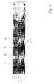
- FIG. 1 shows a schematic representation of a device according to the invention with a rod-shaped electrode 1 and an axial region 2 extending over an (upper) part of the electrode length and containing a material (eg air) whose relative dielectric constant is less than the relative dielectric constant of the to be heated solid 4 is filled.
- the device may also have a plurality of such preferably cylindrical electrodes, wherein preferably the central electrode or the middle electrode row has a corresponding axial region.
- electrodes 1 made of different electrically conductive materials such as structural steel, stainless steel or copper were used, whereby no principal influence of the electrode material was found on the test results.
- one end of the electrode 1 was led across the earth's surface and connected via an electronic matching network to an HF generator with an operating frequency of 13.56 MHz.
- HF generator with an operating frequency of 13.56 MHz.
- Connecting cables consisted of either coaxial cables or copper bands. The temperature in the fixed bed was measured continuously by means of fiber optic sensors.
- the upper portion of the electrode 1 is provided with a guide tube 6, whereby an air gap of defined strength around the electrode 1 is realized around.
- the electrode 1 is surrounded in the upper region by a hollow cylindrical axial air chamber 2, whereby the coupling of the radiated energy of the electrode 1 is realized in particular in the lower axial region and in the region of the lower end of the electrode 1.
- a spatially-selective heating of the solid 4 is possible.
- such an electrode 1 can be used both alone and in combination with further electrodes.
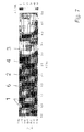
- Fig. 2 shows a schematic representation of a device according to the invention with an electrode 1 and three axial regions of different radial extent.
- the electrode 1 is surrounded over its entire length by a concentric guide tube 6, wherein the guide tube 6 in a central Section has a smaller outer diameter (the electrode 1 always has the same outer diameter).
- the resulting chamber 2 is filled with a dielectric having a lower relative dielectric constant than that of the solid (eg air).
- a dielectric having a lower relative dielectric constant than that of the solid (eg air).
- FIG. 3 shows a schematic representation of a device according to the invention with an electrode 1 and three axial regions 2, 3, 2 of the same radial extent, wherein the central axial region 3 consists of a different material than the outer axial regions 2.
- the electrode 1 is surrounded over its entire length (and even beyond the end remote from the bottom surface - lower end - addition) by a concentric guide tube 6, the electrode 1 in an upper and a lower portion 2 of an air chamber and in a middle Area 3 is surrounded by a water chamber. Due to the higher relative dielectric constant of the water compared to the air, an increased coupling of the energy emitted by the electrode 1 in the central region of the electrode 1 is realized.
- other filling materials are suitable if they meet the requirements for a selective coupling with respect to the dielectric properties.
- the relative dielectric constants of the media should preferably differ from that of the soil by a factor of 3, more preferably by a factor of 5. This is true for both the higher and lower relative dielectric constant materials.
- FIG. 4 shows a schematic illustration of a device according to the invention with five axial regions 2, 3 of equal radial extent, wherein the outer axial regions 2 and the central axial region 2 are made of a different material exist as the remaining axial areas 3.
- the electrode 1 is surrounded over its entire length by a concentric guide tube 6, wherein the electrode 1 is surrounded in individual axial sections of air chambers 2 and water chambers 3. Due to the higher relative dielectric constant of the water compared to air, an increased coupling of the energy radiated from the electrode 1 is realized in those regions of the electrode 1 which are surrounded by water chambers 3.
- soil layers can be spatially-selectively heated in any way. Such an arrangement can be used both alone and in combination with other electrodes.
- the expansions of the axial regions along the electrode and / or the filling materials are variably variable.
- fluid dielectrics such as water or air
- the chambers 2 and 3 can be relatively easily filled or emptied with pumping devices.
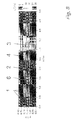
- Fig. 5 shows the temperature profile of a solid bed after heating with a device according to the prior art.
- a high frequency generator with an operating frequency of 13.56 MHz was used.
- the heating time was 4 hours with an effectively injected RF power of 1.65 kW.
- the measuring level is shown at a depth of 0.5 m.
- the electrodes are preferably arranged in a plane perpendicular to the soil surface.
- the parallel arrangement was made in the embodiment only due to the ease of mounting the temperature sensors. Of course, a vertical introduction of the electrodes is not absolutely necessary. It is also possible to introduce the electrodes obliquely into the solid bed (or even parallel to the bottom surface - as in the embodiment).
- the central electrode 1 (diameter 55 mm) was concentrically provided with a guide tube 6 (diameter about 160 mm), wherein an air gap of about 50 mm was realized around the central electrode 1.
- an RF power of 1.7 kW was used at a frequency of 13.56 MHz.
- Operating frequency, position and contacting of the electrodes correspond to the information in FIG. 6.
- the average HF power was 1.2 kW, the heating time 2.5 hours.
- an RF power of 0.8 kW was applied for 1.25 hours (frequency 13.56 MHz).
Landscapes
- Engineering & Computer Science (AREA)
- Life Sciences & Earth Sciences (AREA)
- Structural Engineering (AREA)
- Physics & Mathematics (AREA)
- Soil Sciences (AREA)
- Environmental & Geological Engineering (AREA)
- Paleontology (AREA)
- Electromagnetism (AREA)
- General Life Sciences & Earth Sciences (AREA)
- Mining & Mineral Resources (AREA)
- Thermal Sciences (AREA)
- Civil Engineering (AREA)
- General Engineering & Computer Science (AREA)
- Agronomy & Crop Science (AREA)
- Furnace Details (AREA)
- Processing Of Solid Wastes (AREA)
- Resistance Heating (AREA)
- Physical Or Chemical Processes And Apparatus (AREA)
- Constitution Of High-Frequency Heating (AREA)
- Solid-Sorbent Or Filter-Aiding Compositions (AREA)
Abstract
Description
Die Erfindung betrifft ein Verfahren und eine Vorrichtung zur selektiven dielektrischen Erwärmung eines Feststoffbettes mittels mindestens einer stabförmigen Elektrode mit den in den Oberbegriffen der Ansprüche 1 und 9 genannten Merkmalen. Insbesondere betrifft die vorliegende Erfindung ein Verfahren und eine Vorrichtung zur selektiven Erwärmung von kontaminierten Böden und anderen kontaminierten Feststoffen mittels Stabelektroden.The invention relates to a method and a device for selective dielectric heating of a solid bed by means of at least one rod-shaped electrode having the features mentioned in the preambles of
Die Reinigung von Böden und anderen kontaminierten Medien kann unter Verwendung verschiedener Heizmethoden thermisch unterstützt werden. Bei der Bodensanierung haben sich beispielsweise die thermisch unterstützte Bodenluftabsaugung und die thermisch unterstützte mikrobielle Bodenreinigung etabliert. Eine Temperaturerhöhung beschleunigt in der Regel den Schadstoffaustrag durch die Erhöhung von Dampfdrücken und Mobilitäten, Wasserlöslichkeiten und Bioverfügbarkeit der Kontaminanten. Außerdem können, besonders bei niedriger Umgebungstemperatur, mikrobiologische Reinigungsvorgänge durch Einstellung optimaler Bodentemperaturen unterstützt werden. Bei höheren Temperaturen können Schadstoffe durch die Initiierung von Umwandlungen oder chemischen Reaktionen mit der Bodenmatrix durch Hydrolyse, Oxidation oder Pyrolyse unschädlich gemacht bzw. immobilisiert werden.The cleaning of floors and other contaminated media can be thermally assisted using various heating methods. In soil remediation, for example, thermally assisted soil vapor extraction and thermally assisted microbial soil cleaning have become established. Increasing the temperature usually accelerates pollutant discharge by increasing vapor pressures and mobilities, water solubilities and bioavailability of the contaminants. In addition, especially at low ambient temperature, microbiological cleaning operations can be assisted by setting optimum soil temperatures. At higher temperatures, pollutants can be rendered harmless or immobilized by the initiation of conversions or chemical reactions with the soil matrix by hydrolysis, oxidation or pyrolysis.
Dielektrische Erwärmungsmethoden besitzen insbesondere für in-situ-Anwendungen ein erhebliches Potenzial. Der Einsatz von Radiowellen (z.B. mit einer Hochfrequenz [HF] im Bereich zwischen 1 und 50 MHz - Radiowellen[RW]-Bereich) ermöglicht durch Eindringtiefen im Meter-Bereich die gesteuerte Aufheizung größerer Volumina. Das physikalische Wirkprinzip ist dem eines Mikrowellenofens für Haushalts- und industrielle Anwendungen vergleichbar. Durch dielektrische Heizverfahren können bei Bedarf und ausreichender vorhandener Leistung sehr schnelle Aufheizprozesse realisiert werden.Dielectric heating methods have considerable potential, especially for in-situ applications. The use of radio waves (eg with a high frequency [HF] in the range between 1 and 50 MHz - radio waves [RW] range) allows through penetration depths in the meter range the controlled heating of larger volumes. The physical effect is similar to that of a microwave oven for household and industrial applications. By dielectric Heating process can be realized if needed and sufficient existing power very fast heating processes.
Neben schadstoffhaltigen Böden können auch andere feste Materialien wie Abfälle oder Reststoffe mit diesen Verfahren dekontaminiert werden. Darüber hinaus ist es möglich, Wertstoffe mit Hilfe dieser Methode aus dem Feststoff (z.B. Ölschiefer) zu entfernen und nutzbar zu machen. Außerdem ist auch die thermische Regenerierung von Adsorbermaterialien unter Nutzung der Radiowellen-Erwärmung möglich.In addition to contaminated soils, other solid materials such as waste or residual materials can be decontaminated with these methods. In addition, it is possible to remove recyclables from the solid (e.g., oil shale) using this method and to harness them. In addition, the thermal regeneration of Adsorbermaterialien using the radio wave heating is possible.
Für die Anwendung der dielektrischen Erwärmung in der Praxis ist es essenziell, die gewünschten Temperaturprofile in räumlich ausgedehnten Bereichen oder Kompartimenten realisieren zu können. Für die Erfüllung dieser Anforderung ist die verwendete Elektrodengeometrie (Stabelektroden, ausgedehnte Platten oder Antennen) entscheidend.For the application of dielectric heating in practice, it is essential to be able to realize the desired temperature profiles in spatially extended areas or compartments. To meet this requirement, the electrode geometry used (stick electrodes, extended plates or antennas) is crucial.
Inhomogene Temperaturverteilungen bergen die Gefahr, dass der Sanierungserfolg nicht im gesamten Bereich gewährleistet werden kann oder dass sogar auf Grund einer Rekondensation von bereits freigesetzten Schadstoffen eine erneute Kontamination anderer, ggf. bisher unbelasteter, Feststoffbereiche erfolgt. Kann man von einer Sättigung der Bodenluft mit Schadstoffen bei der entsprechenden Temperatur ausgehen, so ist für eine effektive Entfernung der Kontaminanten über die Gasphase sicherzustellen, dass der konvektive Transport möglichst nur durch Bereiche gleicher oder höherer Temperatur erfolgt. Andererseits ist es beim Vorliegen sehr unterschiedlicher lokaler Schadstoffkonzentrationen im Boden ökonomisch sinnvoll, bevorzugt die hochkontaminierten Bereiche zu erwärmen und darüber hinaus die vorgenannte Bedingung bei der Realisierung der Bodenluftabsaugung zu berücksichtigen.Inhomogeneous temperature distributions pose the risk that the rehabilitation success can not be guaranteed in the entire area or that even due to a recondensation of already released pollutants, a renewed contamination of other, possibly previously unloaded, solid areas occurs. If it can be assumed that saturation of the soil air with pollutants at the corresponding temperature, effective removal of the contaminants via the gas phase must be ensured that the convective transport takes place only through areas of the same or higher temperature. On the other hand, it is economically useful in the presence of very different local pollutant concentrations in the soil, preferably to heat the highly contaminated areas and beyond to take into account the above condition in the realization of the Bodenluftabsaugung.
Obwohl Plattenelektroden theoretisch für die Erfüllung dieser Randbedingungen am besten geeignet sind, werden (besonders bei in-situ-Anwendungen) sehr oft stabförmige Elektroden eingesetzt, da diese verhältnismäßig einfach in den Boden eingebracht werden können, weil dafür die Verwendung konventioneller Bohrtechnik möglich ist. Durch vertikale Stabelektroden können prinzipiell auch tiefer liegende Boden- bzw. Feststoffschichten erreicht und definiert erwärmt werden.Although plate electrodes are theoretically most suitable for meeting these constraints, rod-shaped electrodes are often used (especially in in-situ applications) because they are relatively easy to ground can be introduced because the use of conventional drilling technology is possible. By vertical stick electrodes in principle also deeper lying soil or solid layers can be achieved and heated in a defined manner.
In Abhängigkeit von den Bodeneigenschaften tritt jedoch oft eine starke Dämpfung der elektromagnetischen Welle entlang von stabförmigen Elektroden auf, wodurch bevorzugt die oberen Boden- bzw. Feststoffschichten aufgeheizt werden und in den tiefergelegenen Schichten kein ausreichender Temperaturanstieg zu verzeichnen ist.Depending on the soil properties, however, there is often a strong attenuation of the electromagnetic wave along rod-shaped electrodes, whereby preferably the upper soil or solid layers are heated and in the deeper layers is not recorded a sufficient increase in temperature.
Die Verwendung von Stabelektroden bei der Radiowellen-Bodenerwärmung ist unter Anderem aus
Eine Lösungsmöglichkeit für die Problematik der beschränkten Erreichbarkeit für die dielektrische Erwärmung besteht darin, zu geringeren Frequenzen des elektromagnetischen Feldes überzugehen. Diese Option ist jedoch unter praktischen Gesichtspunkten auf Grund der kommerziellen Verfügbarkeit von HF-Spannungsquellen sehr eingeschränkt. Im Niederfrequenz(NF)-Bereich (z.B. 50 oder 60 Hz) tritt ein solcher Effekt verstärkter Dämpfung nicht auf, die Erwärmung beruht jedoch dann praktisch ausschließlich auf ohmschen Verlusten. Für trockene Medien ist die Methode der NF-Erwärmung in der Regel nicht anwendbar.One solution to the problem of limited availability for dielectric heating is to move to lower frequencies of the electromagnetic field. However, this option is very limited in practical terms due to the commercial availability of RF power sources. In the low frequency (NF) range (eg 50 or 60 Hz), such an effect of increased attenuation does not occur, the heating is then based almost exclusively on ohmic losses. For dry media, the method of NF-heating is usually not applicable.
Bei Vorrichtungen zur dielektrischen Erwärmung nach dem Stand der Technik besteht nachteilhafterweise nicht die Möglichkeit, den Energieeintrag entlang der stabförmigen Elektroden gezielt und variabel zu beeinflussen. So ist es beispielsweise nicht möglich, hochkontaminierte Horizonte in Böden und Feststoffen räumlich-selektiv und unter Umständen sukzessive aufzuheizen und die Verfahrensweise in Abhängigkeit vom Sanierungsfortschritt während des Prozesses anzupassen.In the case of devices for dielectric heating according to the prior art, it is disadvantageously not possible to selectively and variably influence the energy input along the rod-shaped electrodes. For example, it is not possible to heat up highly contaminated horizons in soils and solids in a spatially selective and possibly successive manner, and to adapt the procedure to suit the rehabilitation progress during the process.
Eine selektive Erwärmung bestimmter Bodenbereiche wird nach dem Stand der Technik erreicht (
Es ist daher Aufgabe der vorliegenden Erfindung, ein Verfahren und eine Vorrichtung zur räumlich-selektiven Erwärmung und/oder Reinigung eines Feststoffbettes anzugeben, mit welchen ein Feststoffbett (d.h. z.B. ein Bodenvolumen) entlang des Verlaufes von stabförmigen Elektroden selektiv und gezielt erwärmt werden kann.It is therefore an object of the present invention to provide a method and an apparatus for spatially-selective heating and / or cleaning of a solid bed, with which a solid bed (ie, for example, a bottom volume) along the course of rod-shaped electrodes can be selectively and selectively heated.
Insbesondere soll es möglich sein, dass die Einkopplung von elektromagnetischen Wellen in das die Elektroden umgebende Material derart erfolgt, dass sich bestimmte Abschnitte eines Boden- oder Feststoffhorizontes bevorzugt erwärmen, andere jedoch nahezu nicht aufgeheizt werden.In particular, it should be possible for the coupling of electromagnetic waves into the material surrounding the electrodes to take place in such a way that certain sections of a soil or solid horizon preferentially heat up while others are almost not heated.
Diese Aufgaben werden erfindungsgemäß durch ein Verfahren und eine Vorrichtung mit den in den Oberbegriffen des Anspruchs 1 (Verfahrensanspruch) und des Anspruchs 9 (Vorrichtungsanspruch) genannten Merkmalen im Zusammenwirken mit den Merkmalen im Oberbegriff gelöst.These objects are achieved according to the invention by a method and a device having the features mentioned in the preambles of claim 1 (method claim) and claim 9 (device claim) in conjunction with the features in the preamble.
Das erfindungsgemäße Verfahren zur selektiven dielektrischen Erwärmung eines Feststoffbettes unter Verwendung einer oder mehrerer stabförmiger Elektroden ist durch das Einkoppeln von elektromagnetischer Strahlung in das Feststoffbett über die mindestens eine stabförmige Elektrode gekennzeichnet, wobei zumindest in einem Teilbereich der Elektrode zwischen der Mantelfläche der Elektrode und dem Feststoffbett ein Material angeordnet wird, dessen relative Dielektrizitätskonstante sich von der relativen Dielektrizitätskonstanten des Feststoffbettes deutlich unterscheidet.The inventive method for selective dielectric heating of a solid bed using one or more rod-shaped electrodes is characterized by the coupling of electromagnetic radiation in the solid bed on the at least one rod-shaped electrode, wherein at least in a portion of the electrode between the lateral surface of the electrode and the solid bed Material is arranged, the relative dielectric constant of which differs significantly from the relative dielectric constant of the solid bed.
Die vorliegende Erfindung bezieht sich nicht auf Axialdipole oder Koaxialantennen, sondern auf einfache Elektroden, die vorzugsweise mindestens paarweise in das zu erwärmende Medium eingeführt werden. Dies hat den Vorteil, dass sich das elektrische Feld zwischen den Elektroden unterschiedlicher Polarität ausbildet und somit eine homogenere Volumenerwärmung möglich ist. Außerdem bietet das Einbringen einfacher stabförmiger Elektroden, beispielsweise Stahlrohren, verfahrenstechnische Vorteile gegenüber der Anwendung von Koaxialantennen.The present invention does not relate to axial dipoles or coaxial antennas, but to simple electrodes, which are preferably introduced into the medium to be heated at least in pairs. This has the advantage that the electric field between the electrodes of different polarity is formed and thus a more homogeneous volume heating is possible. In addition, the introduction of simple rod-shaped electrodes, for example steel tubes, offers procedural advantages over the use of coaxial antennas.
Das erfindungsgemäße Verfahren weist folgende Verfahrensschritte auf: Einbringen mindestens einer stabförmigen Elektrode in ein Feststoffbett, und Einkoppeln von elektromagnetischer Strahlung in das Feststoffbett über die mindestens eine stabförmige Elektrode, wobei zumindest in einem Teilbereich der Elektrode zwischen der Mantelfläche der Elektrode und dem Feststoffbett ein Material angeordnet wird, dessen relative Dielektrizitätskonstante sich von der relativen Dielektrizitätskonstante des Feststoffbettes unterscheidet.The method according to the invention comprises the following method steps: introducing at least one rod-shaped electrode into a solid bed, and coupling electromagnetic radiation into the solid bed via the at least one rod-shaped electrode, wherein a material is arranged between the outer surface of the electrode and the solid bed at least in a partial region of the electrode whose relative dielectric constant is different from the relative dielectric constant of the solid bed.
Vorzugsweise wird die eine Elektrode bzw. werden die mindestens zwei Elektroden zur Erzeugung eines elektromagnetischen Feldes im Feststoff mittels eines HF-Generators gespeist. Da sich die vorliegende Erfindung nicht auf Axialdipole oder Koaxialantennen bezieht, wird die mindestens eine stabförmige Elektrode mit einer Hochfrequenzspannung (mittels des HF-Generators) gespeist, die lediglich eine Polarität (so genannte "heiße" bzw. "kalte", geerdete Elektrode) aufweist. Hingegen werden bei Koaxialantennenanordnungen beide Phasen in die Antenne gespeist und somit in den zu erwärmenden Bodenbereich geführt. Bei der (bevorzugten) Verwendung zweier stabförmige Elektroden werden diese ebenfalls mit nur einer Phase gespeist, wobei sich die Polarität der eingespeisten Hochfrequenzspannung für die beiden Elektroden unterscheidet. Bei mehr als zwei Elektroden ist es vorgesehen, dass sich die Polarität (der eingespeisten Hochfrequenzspannung) mindestens zweier Elektroden unterscheidet.Preferably, the one electrode or the at least two electrodes for generating an electromagnetic field in the solid is fed by means of an HF generator. Since the present invention does not relate to axial dipoles or coaxial antennas, the at least one rod-shaped electrode is fed with a high-frequency voltage (by means of the HF generator) which has only one polarity (so-called "hot" or "cold", grounded electrode) , On the other hand, in coaxial antenna arrangements, both phases are fed into the antenna and thus guided into the floor area to be heated. In the (preferred) use of two rod-shaped electrodes, these are also fed with only one phase, wherein the polarity of the injected high-frequency voltage for the two electrodes differs. With more than two electrodes, it is provided that the polarity (of the injected high-frequency voltage) of at least two electrodes differs.
Vorzugsweise wird die mindestens eine stabförmige Elektrode in das Feststoffbett senkrecht in Bezug auf die Oberfläche des Feststoffbettes eingebracht und die Kontaktierung erfolgt oberhalb der Oberfläche. Vorzugsweise wird in einem Teilbereich entlang der Elektrode ein Material zwischen Elektrodenoberfläche und Festbett angeordnet, dessen relative Dielektrizitätskonstante niedriger ist als die relative Dielektrizitätskonstante des Feststoffbettes. Vorzugsweise wird zusätzlich im Bereich des der Oberfläche des Feststoffbettes abgewandten Endes der Elektrode ein Material angeordnet wird, dessen relative Dielektrizitätskonstante sich von der relativen Dielektrizitätskonstante des Feststoffbettes unterscheidet. Vorzugsweise werden in mindestens zwei Abschnitten entlang der Längsachse der Elektrode Materialien unterschiedlicher relativer Dielektrizitätskonstante zwischen Mantelfläche der Elektrode und Feststoffbett angeordnet. Vorzugsweise wird in mindestens zwei Abschnitten entlang der Elektrode ein Material mit bereichsweise unterschiedlicher radialer Ausdehnung zwischen Mantelfläche der Elektrode und Feststoffbett angeordnet, welches eine relative Dielektrizitätskonstante aufweist, die sich von der relativen Dielektrizitätskonstante des Feststoffbettes unterscheidet. Vorzugsweise wird das Material, dessen relative Dielektrizitätskonstante sich von der relativen Dielektrizitätskonstante des Feststoffbettes unterscheidet, konzentrisch um die Elektrode herum angeordnet. Vorzugsweise wird als Material, dessen relative Dielektrizitätskonstante niedriger ist als die Dielektrizitätskonstante des Feststoffbettes, Luft verwendet. Vorzugsweise wird in Bezug auf das Volumen als Hauptbestandteil des Materials, dessen relative Dielektrizitätskonstante höher ist als die Dielektrizitätskonstante des Feststoffbettes, Wasser verwendet. Vorzugsweise wird das Material, dessen relative Dielektrizitätskonstante sich von der relativen Dielektrizitätskonstante des Feststoffbettes unterscheidet, in ein zur Elektrode konzentrisch angeordnetes Führungsrohr eingebracht. Vorzugsweise wird das Material, dessen relative Dielektrizitätskonstante sich von der relativen Dielektrizitätskonstante des Feststoffbettes unterscheidet, in ein zur Elektrode konzentrisch angeordnetes Führungsrohres in vordefinierten Abschnitten eingebracht.Preferably, the at least one rod-shaped electrode is introduced into the solid bed perpendicular with respect to the surface of the solid bed and the contacting takes place above the surface. Preferably, a material is arranged between electrode surface and fixed bed in a partial area along the electrode whose relative dielectric constant is lower than the relative dielectric constant of the solid bed. In addition, in the region of the end of the electrode facing away from the surface of the solid bed, a material is preferably additionally arranged whose relative dielectric constant differs from the relative dielectric constant of the solid bed. Preferably, materials of different relative dielectric constant are arranged between the lateral surface of the electrode and the solid bed in at least two sections along the longitudinal axis of the electrode. Preferably, in at least two sections along the electrode, a material with regions of different radial extent between lateral surface of the electrode and solid bed is arranged, which has a relative dielectric constant, the differs from the relative dielectric constant of the solid bed. Preferably, the material whose relative dielectric constant is different from the relative dielectric constant of the solid bed is arranged concentrically around the electrode. Preferably, air is used as the material whose relative dielectric constant is lower than the dielectric constant of the solid bed. Preferably, water is used in terms of volume as the main component of the material whose relative dielectric constant is higher than the dielectric constant of the solid bed. Preferably, the material, the relative dielectric constant of which differs from the relative dielectric constant of the solid bed, is introduced into a guide tube arranged concentrically with respect to the electrode. Preferably, the material whose relative dielectric constant is different from the relative dielectric constant of the solid bed is introduced into a guide tube arranged concentrically with the electrode in predefined sections.
Vorzugsweise werden zusätzlich aus dem Feststoffbett Gase abgesaugt. Vorzugsweise wird die eine Elektrode bzw. werden die mindestens zwei Elektroden über ein elektronisches Anpassnetzwerk mit dem HF-Generator verbunden. Vorzugsweise wird durch die Wahl der zur Elektrode senkrechten Ausdehnung der axialen Bereiche entlang der Elektrode/Elektroden und/oder durch die Wahl der die axialen Bereiche ausfüllenden Materialien eine räumlich-selektive Erwärmung von Schichten des Feststoffes senkrecht zur Elektrodenrichtung gesteuert.Preferably, gases are additionally removed by suction from the solid bed. Preferably, the one or the at least two electrodes are connected to the RF generator via an electronic matching network. Preferably, the choice of the perpendicular to the electrode extension of the axial regions along the electrode / electrodes and / or by the choice of the axial regions filling materials, a spatially-selective heating of layers of the solid is controlled perpendicular to the electrode direction.
Die erfindungsgemäße Vorrichtung zur räumlich-selektiven Erwärmung eines Feststoffbettes mittels elektromagnetischer Strahlung weist mindestens eine (bevorzugt mindestens zwei) stabförmige Elektrode(n) auf, wobei zumindest in einem Teilbereich der mindestens einen Elektrode zwischen der Mantelfläche der Elektrode und dem Feststoffbett ein Material angeordnet ist, dessen relative Dielektrizitätskonstante sich von der relativen Dielektrizitätskonstante des Feststoffbettes unterscheidet. Vorzugsweise weist die Vorrichtung mindestens zwei Elektroden auf, deren Längsachsen parallel zueinander angeordnet sind.The device according to the invention for spatially selective heating of a solid bed by means of electromagnetic radiation has at least one (preferably at least two) rod-shaped electrode (s), wherein a material is arranged at least in a partial region of the at least one electrode between the lateral surface of the electrode and the solid bed, the relative dielectric constant of which differs from the relative dielectric constant of the solid bed. Preferably, the device has at least two electrodes whose longitudinal axes are arranged parallel to one another.
Vorzugsweise weist die Vorrichtung mindestens eine HF-Quelle (vorzugsweise einen HF-Generator) zur Speisung der mindestens einen Elektrode mit einer HF-Spannung auf. Der HF-Generator besitzt vorzugsweise eine Arbeitsfrequenz im Bereich zwischen 1 und 50 MHz. Der HF-Generator versorgt die jeweiligen Elektroden (da sich die vorliegende Erfindung nicht auf Axialdipole oder Koaxialantennen bezieht) mit einer Hochfrequenzspannung, die lediglich eine Polarität ("heiße" oder "kalte", geerdete Elektrode) aufweist. Hingegen werden bei Koaxialantennenanordnungen beide Phasen der HF-Spannung in die Antenne gespeist.The device preferably has at least one HF source (preferably an HF generator) for feeding the at least one electrode with an HF voltage. The HF generator preferably has an operating frequency in the range between 1 and 50 MHz. The RF generator supplies the respective electrodes (since the present invention does not refer to axial dipoles or coaxial antennas) with a high frequency voltage having only one polarity ("hot" or "cold" grounded electrode). On the other hand, in coaxial antenna arrangements, both phases of the RF voltage are fed into the antenna.
Vorzugsweise ist die mindestens eine Elektrode zylinderförmig ausgebildet. Vorzugsweise ist in einem Teilbereich zwischen der Mantelfläche der Elektrode und dem zu erwärmenden Feststoff ein Material angeordnet, dessen relative Dielektrizitätskonstante sich von der relativen Dielektrizitätskonstante des Feststoffbettes unterscheidet. Vorzugsweise ein jeweils erstes Ende der Elektrode mit dem HF-Generator verbunden. Vorzugsweise ist die mindestens eine Elektrode über Koaxialleitungen und über ein elektronisches Anpassnetzwerk mit dem HF-Generator verbunden. Vorzugsweise ist mindestens eine Elektrode mit einer Vorrichtung zur Absaugung von Schadstoffen verbunden. Vorzugsweise ist in mindestens einem Teil entlang der Elektrode zwischen Mantelfläche der Elektrode und zu erwärmenden Feststoff ein Material angeordnet, dessen relative Dielektrizitätskonstante sich von der relativen Dielektrizitätskonstante des Feststoffbettes derart unterscheidet, dass dadurch die Energieeinkopplung in den Feststoff reduziert wird. Vorzugsweise weist die Vorrichtung mindestens zwei Abschnitte entlang der Längsachse der Elektrode auf, welche zwischen der Mantelfläche der Elektrode und dem Feststoff Materialien unterschiedlicher radialer Ausdehnung aufweisen, wobei die Materialien eine relative Dielektrizitätskonstante aufweisen, die sich von der relativen Dielektrizitätskonstante des Feststoffbettes unterscheidet. Vorzugsweise weist die Vorrichtung mindestens zwei Abschnitte entlang der Längsachse der (mindestens einen) Elektrode auf, welche zwischen der Mantelfläche der Elektrode und dem Feststoff Materialien unterschiedlicher Dielektrizitätskonstanten aufweisen, deren relative Dielektrizitätskonstante sich sowohl untereinander als auch vom zu erwärmenden Feststoff unterscheiden.Preferably, the at least one electrode is cylindrical. Preferably, a material whose relative dielectric constant differs from the relative dielectric constant of the solid bed is arranged in a partial region between the lateral surface of the electrode and the solid to be heated. Preferably, a respective first end of the electrode connected to the RF generator. Preferably, the at least one electrode is connected via coaxial lines and via an electronic matching network with the RF generator. Preferably, at least one electrode is connected to a device for the extraction of pollutants. Preferably, a material whose relative dielectric constant differs from the relative dielectric constant of the solid bed in such a way that the energy is coupled into the solid is arranged in at least one part along the electrode between lateral surface of the electrode and solid to be heated. The device preferably has at least two sections along the longitudinal axis of the electrode which have materials of different radial extent between the lateral surface of the electrode and the solid, the materials having a relative dielectric constant which differs from the relative dielectric constant of the solid bed. Preferably, the device has at least two sections along the longitudinal axis of the (at least one) electrode, which between the Jacket surface of the electrode and the solid materials of different dielectric constants have, the relative dielectric constant differ both with each other and from the solid to be heated.
Vorzugsweise ist das Material, dessen relative Dielektrizitätskonstante niedriger als die relative Dielektrizitätskonstante des Feststoffbettes ist, Luft. Vorzugsweise ist (in Bezug auf das Volumen) der Hauptbestandteil des Materials, dessen relative Dielektrizitätskonstante höher als die relative Dielektrizitätskonstante des Feststoffbettes ist, Wasser.Preferably, the material whose relative dielectric constant is lower than the relative dielectric constant of the solid bed is air. Preferably (in volume) the major constituent of the material whose relative dielectric constant is higher than the relative dielectric constant of the solid bed is water.
Vorzugsweise weist die Vorrichtung (bei mindestens einer, vorzugsweise bei jeder Elektrode) ein zur Längsachse der Elektrode konzentrisch angeordnetes Führungsrohr auf, innerhalb dessen das Material, dessen relative Dielektrizitätskonstante sich von der relativen Dielektrizitätskonstante des Feststoffbettes unterscheidet, angeordnet ist. Vorzugsweise sind innerhalb des konzentrisch angeordneten Führungsrohres mindestens zwei axiale Abschnitte vorgesehen, innerhalb derer Materialien unterschiedlicher relativer Dielektrizitätskonstante angeordnet sind, wobei die Abschnitte mit einer Vorrichtung zur flexiblen Einbringung und Entfernung der Materialien verbunden sind.Preferably, the device (at least one, preferably at each electrode) on a to the longitudinal axis of the electrode concentrically arranged guide tube, within which the material whose relative dielectric constant is different from the relative dielectric constant of the solid bed, is arranged. Preferably, within the concentrically arranged guide tube at least two axial sections are provided, within which materials of different relative dielectric constant are arranged, which sections are connected to a device for flexible introduction and removal of the materials.
Vorzugsweise werden Vorrichtungen eingesetzt, die eines oder mehrere der folgenden Merkmale aufweisen:
- Stabförmige Elektroden mit zylindrischer Geometrie werden senkrecht zur Oberfläche in das Festbett eingebracht und oberhalb der Oberfläche mit elektrischen Anschlüssen versehen. In einer bevorzugten Ausführungsvariante des erfindungsgemäßen Verfahrens werden mindestens zwei Elektroden, besonders bevorzugt drei parallele Reihen von Elektroden in das Feststoffbett eingebracht, wobei die Längsachsen parallel zueinander verlaufen.
- Der Bereich in radialer Richtung zwischen der Elektrodenoberfläche und dem zu erwärmenden Material wird abschnittsweise entweder vollständig oder teilweise mit einem Stoff gefüllt, dessen dielektrische Eigenschaften und insbesondere dessen relative Dielektrizitätskonstante bei der angewandten Hochfrequenz sich von denen des zu erwärmenden Feststoffs unterscheiden.
- Dieser Bereich kann in einer bevorzugten Variante auch das der Kontaktierung abgewandte Ende der Elektrode vollständig umfassen.
- In einer weiteren bevorzugten Variante wird die Ausdehnung des Bereiches in radialer Richtung zwischen Elektrodenoberfläche und dem zu erwärmenden Feststoff entlang der Elektrodenlängsachse variiert.
- Vorzugsweise wird das Material innerhalb eines zur Elektrode konzentrisch angeordneten Führungsrohres eingebracht. In einer besonders bevorzugten Ausführungsvariante wird das Material innerhalb eines zur Elektrode konzentrisch angeordneten Führungsrohres innerhalb vordefinierter axialer Abschnitte eingebracht.
- Als bevorzugte Medien, die sich in ihren dielektrischen Eigenschaften von denen des zu erwärmenden Feststoffs unterscheiden, werden Luft und Wasser eingesetzt.
- Rod-shaped electrodes with a cylindrical geometry are introduced perpendicular to the surface in the fixed bed and provided above the surface with electrical connections. In a preferred embodiment of the method according to the invention, at least two electrodes, more preferably three parallel rows of electrodes are introduced into the solid bed, the longitudinal axes being parallel to one another.
- The region in the radial direction between the electrode surface and the material to be heated is filled either completely or partially with a substance whose dielectric properties and in particular its relative dielectric constant at the applied high frequency differ from those of the solid to be heated.
- In a preferred variant, this region can also completely cover the end of the electrode facing away from the contacting.
- In a further preferred variant, the extent of the region in the radial direction between the electrode surface and the solid to be heated along the electrode longitudinal axis is varied.
- Preferably, the material is introduced within a guide tube concentric with the electrode. In a particularly preferred embodiment variant, the material is introduced within a guide tube arranged concentrically with respect to the electrode within predefined axial sections.
- As preferred media, which differ in their dielectric properties from those of the solid to be heated, air and water are used.
Die radiale Ausdehnung des zwischen Mantelfläche der Elektrode und Feststoffbett eingebrachten Materials beträgt vorzugsweise zwischen 30% und 300% und bevorzugt zwischen 50% und 150% des Durchmessers der Elektrode.The radial extent of the material introduced between the lateral surface of the electrode and the solid bed is preferably between 30% and 300% and preferably between 50% and 150% of the diameter of the electrode.
Zur dielektrischen Erwärmung des Feststoffes ist das Elektrodensystem vorzugsweise über ein elektronisches Anpassnetzwerk mit einem HochfrequenzGenerator verbunden. Hierdurch wird ein optimaler Energietransfer in das zu erwärmende Medium sichergestellt, wobei sich eine große Flexibilität hinsichtlich der Materialeigenschaften (trocken, feuchte, porös, massiv) ergibt.For dielectric heating of the solid, the electrode system is preferably connected to a high-frequency generator via an electronic matching network. As a result, an optimal energy transfer is ensured in the medium to be heated, resulting in a great flexibility in terms of material properties (dry, moist, porous, solid).
In einem bevorzugten Anwendungsfall erfolgt der Schadstoffaustrag aus dem Boden über eine Anlage zur Bodenluftabsaugung. Besonders bevorzugt ist dabei die Variante, mindestens eine stabförmige Elektrode gleichzeitig als Absaugbrunnen für die Bodenluft einzusetzen.In a preferred application, the pollutant discharge from the soil via a system for Bodenluftabsaugung. Particularly preferred is the Variant to use at least one rod-shaped electrode simultaneously as a suction well for the soil air.
Vorzugsweise weist die Vorrichtung ein zur Längsachse der stabförmigen Elektrode konzentrisch angeordnetes füllbares Führungsrohr auf, innerhalb dessen das (Füll-)Material (beispielsweise Luft oder Wasser) angeordnet ist. Neben den bevorzugten Materialien Luft und Wasser kann für bestimmte Applikationen die Verwendung eines Inertgases wie Stickstoff als Füllmaterial vorteilhaft sein. In einer bevorzugten Ausführungsvariante erstreckt sich dieses Führungsrohr über die gesamte im Feststoff befindliche Elektrodenlänge.The device preferably has a fillable guide tube arranged concentrically to the longitudinal axis of the rod-shaped electrode, within which the (filling) material (for example air or water) is arranged. In addition to the preferred materials air and water, the use of an inert gas such as nitrogen as filler material may be advantageous for certain applications. In a preferred embodiment, this guide tube extends over the entire electrode length located in the solid.
Bei der Verwendung mehrerer Elektroden (bevorzugt zwei Elektroden, besonders bevorzugt drei parallele Reihen von Elektroden) beträgt der Abstand zwischen den Elektroden vorzugsweise zwischen 30 cm und 5 m, besonders bevorzugt zwischen 50 cm und 3 m. Die Länge der Elektroden richtet sich nach der Tiefe bzw. der Ausdehnung des zu erwärmenden Bereichs und beträgt in der Regel mehrere Meter. Die radiale Ausdehnung des mit einem Medium, dessen dielektrischen Eigenschaften sich von dem zu erwärmenden Material unterscheiden, gefüllten Bereiches ist, beträgt vorzugsweise zwischen 5 cm und 30 cm.When using a plurality of electrodes (preferably two electrodes, particularly preferably three parallel rows of electrodes), the distance between the electrodes is preferably between 30 cm and 5 m, particularly preferably between 50 cm and 3 m. The length of the electrodes depends on the depth or extent of the area to be heated and is usually several meters. The radial extent of the region filled with a medium whose dielectric properties differ from the material to be heated is preferably between 5 cm and 30 cm.
Die Erfindung beruht auf Befunden, dass die Erwärmung des Feststoffes entlang von stabförmigen Elektroden durch die folgenden unterschiedlichen Mechanismen gezielt beeinflusst werden kann:
- 1. Eine selektive Erwärmung ist dadurch zu realisieren, dass in axialen Bereichen, in denen keine oder nur eine geringe Erwärmung des Feststoffs bzw. Bodens realisiert werden soll, ein die Stabelektroden umgebender, vorzugsweise radialer Bereich mit einem Medium mit geringer relativer Dielektrizitätskonstante (d.h. geringerer relativer Dielektrizitätskonstante als die des zu erwärmenden Feststoffs) gefüllt ist. Der zu erwärmende Bereich ist dadurch gekennzeichnet, dass an dieser Stelle die Dielektrizitätskonstante des Füllmediums höher ist.
- 2. Eine selektive Erwärmung ist auch dadurch zu realisieren, dass die radiale Ausdehnung des unter 1. beschriebenen Bereiches, der mit einem Medium mit niedriger relativer Dielektrizitätskonstante ausgefüllt ist, variiert wird. Die Feststoffbereiche, wo der Abstand geringer ist, werden in diesem Fall stärker erwärmt.
- 3. Weiterhin können der Energieeintrag und die Erwärmung des Feststoffes durch die Füllung des axialen Bereiches mit Medien unterschiedlicher relativer Dielektrizitätskonstante geregelt werden. In diesem Fall werden die Bereiche, in denen der Zwischenraum zwischen Elektrode und Feststoff mit einem Medium hoher Dielektrizitätskonstante (z.B. Wasser mit ca. 80) gefüllt ist, gegenüber denen, die mit einem Medium mit niedriger relativer Dielektrizitätskonstante (z.B. Luft mit 1) gefüllt sind, verstärkt erwärmt. In einer bevorzugten Ausführung soll dieser Bereich durch geeignete Maßnahmen veränderbar, d.h. variabel hinsichtlich seiner Ausdehnung entlang der Elektrode, sein. So ist es beispielsweise möglich, dass die axialen Bereiche durch unterschiedliche Kammern ausgebildet sind, wobei die einzelnen Kammern hohlzylinderförmig konstruiert sind. Erfindungsgemäß können die Kammern während der Erwärmung des Bodens mit unterschiedlichen Materialien/Medien befüllt werden (hierbei eignen sich besonders flüssige und gasförmige Materialien wie Wasser bzw. Luft, die beispielsweise mittels Schläuchen in die Kammern gefüllt oder aus den Kammern abgesaugt werden können), so dass die Einkopplung der durch die stabförmige Elektrode abgestrahlten Energie in die einzelnen Feststoff- bzw. Bodenschichten räumlich-selektiv gesteuert werden kann.
- 4. Die selektive Erwärmung kann auch durch Kombination der vorgenannten Prinzipien, also beispielsweise sowohl durch Variation der Materialien in unterschiedlichen axialen Bereichen mindestens einer Elektrode als auch durch Variation der radialen Ausdehnung der unterschiedlichen axialen Bereiche realisiert werden.
- 1. A selective heating is to be realized in that in axial regions, in which no or only a slight warming of the solid or soil is to be realized, a surrounding the rod electrodes, preferably radial region with a medium having a low relative dielectric constant (ie lesser Relative dielectric constant than that of the solid to be heated) is filled. The area to be heated is characterized in that at this point the dielectric constant of the filling medium is higher.
- 2. Selective heating can also be achieved by varying the radial extent of the region described in 1., which is filled with a medium having a low relative dielectric constant. The solid areas where the distance is less are heated more in this case.
- 3. Furthermore, the energy input and the heating of the solid can be controlled by the filling of the axial region with media of different relative dielectric constant. In this case, the areas where the gap between electrode and solid is filled with a high dielectric constant medium (eg, water of about 80) are compared with those filled with a medium of low relative dielectric constant (eg, air of 1) , heated up. In a preferred embodiment, this area should be variable by suitable measures, ie be variable in terms of its extension along the electrode. Thus, for example, it is possible that the axial regions are formed by different chambers, wherein the individual chambers are constructed in a hollow cylinder. According to the invention, the chambers can be filled with different materials / media during the heating of the floor (here, in particular, liquid and gaseous materials such as water or air, which can be filled into the chambers by means of hoses or sucked out of the chambers, for example), so that the coupling of the energy radiated by the rod-shaped electrode into the individual solid or soil layers can be spatially-selectively controlled.
- 4. The selective heating can also be realized by combining the aforementioned principles, that is, for example, both by varying the materials in different axial regions of at least one electrode and by varying the radial extent of the different axial regions.
Durch die Etablierung eines radialen Bereiches mit Verwendung eines Füllmediums (Material) mit einer niedrigeren relativen Dielektrizitätskonstante als der des Feststoffs bzw. Bodens wird die Einkopplung der elektromagnetischen Welle in das Material (z.B. den kontaminierten Boden) im entsprechenden Stabelektrodenabschnitt stark verringert und somit die Dämpfung der Welle reduziert. Durch die Variation des Durchmessers des radialen Bereiches wird der Abstand zwischen Elektrodenwand und Medium so verändert, dass die Energieeinkopplung in einem Bereich mit geringem Abstand bevorzugt erfolgt. Durch das Füllen des radialen Bereiches zwischen Elektrodenwand und Feststoff mit einem Medium mit höherer relativer Dielektrizitätskonstante (beispielsweise Wasser mit εr ≈ 80; in der Regel deutlich höher als die des zu erwärmenden Mediums) wird im entsprechenden Abschnitt eine selektive Energieeinkopplung und Erwärmung realisiert.By establishing a radial region using a filling medium (material) with a lower relative dielectric constant than that of the Solid or soil, the coupling of the electromagnetic wave in the material (eg the contaminated soil) is greatly reduced in the corresponding rod electrode section and thus reduces the damping of the shaft. By varying the diameter of the radial region of the distance between the electrode wall and the medium is changed so that the energy coupling is preferably carried out in a region with a small distance. By filling the radial area between the electrode wall and the solid with a medium having a higher relative dielectric constant (for example water with ε r ≈ 80, generally much higher than that of the medium to be heated), a selective energy coupling and heating is realized in the corresponding section.
Die Etablierung eines Bereiches um die Elektrode(n), der mit einem Medium niedriger Dielektrizitätskonstante gefüllt ist, führt außerdem effektiv zu einer Vergrößerung des Elektrodendurchmessers, was wiederum die Überhitzung des Nahbereiches der Elektroden verhindert. Dieser Effekt beruht auf der starken Abnahme des elektrischen Feldes in radialer Richtung von der stabförmigen Elektrode.
Vorzugsweise sollte sich die relative Dielektrizitätskonstante von der des Feststoffes um mindestens den Faktor 3, besonders bevorzugt um den Faktor 10 unterscheiden.The establishment of a region around the electrode (s) filled with a low-dielectric-constant medium also effectively increases the diameter of the electrode, which in turn prevents overheating of the vicinity of the electrodes. This effect is due to the strong decrease of the electric field in the radial direction of the rod-shaped electrode.
The relative dielectric constant should preferably differ from that of the solid by at least the
Die erfindungsgemäßen Lösungen erlauben es, die Radiowellen-Feststofferwärmung entlang stabförmiger Elektroden so zu verbessern, dass ein selektiver Energieeintrag im gewünschten Bereich (d.h. räumlich-selektiv) realisiert werden kann und dass dieser Bereich im Verlaufe der Behandlungsmaßnahme ohne großen technischen Aufwand veränderbar ist.The solutions according to the invention make it possible to improve the radio-wave solid-state heating along rod-shaped electrodes in such a way that selective energy input in the desired region (i.e., spatially-selective) can be realized and that this region can be changed without great technical effort in the course of the treatment measure.
Als Elektrodenmaterial kann beispielsweise Baustahl verwendet werden. Durch eine Perforation der Elektrode ist es außerdem auf dem Gebiet der Bodensanierung möglich, eine thermisch unterstützte Bodenluftabsaugung durch die Elektrode zu realisieren.As an electrode material, for example, structural steel can be used. By perforating the electrode, it is also possible in the field of soil remediation to realize a thermally assisted Bodenluftabsaugung by the electrode.
Die Erfindung wird nachstehend anhand von schematischen Darstellungen und anhand von Ausführungsbeispielen näher erläutert.The invention is explained below with reference to schematic representations and exemplary embodiments.
Es zeigen:
- Fig. 1
- eine schematische Darstellung einer erfindungsgemäßen Vorrichtung mit einem sich über einen (oberen) Teil der Elektrodenlänge erstreckenden, axialen Bereich aus einem Material, dessen relative Dielektrizitätskonstante sich von der relativen Dielektrizitätskonstante des diesen Bereich umgebenden Feststoffbettes signifikant unter-scheidet,
- Fig. 2
- eine schematische Darstellung einer erfindungsgemäßen Vorrichtung mit drei axialen Bereichen, wobei der mittlere axiale Bereich eine geringere radiale Ausdehnung als die äußeren beiden axialen Bereiche aufweist,
- Fig. 3
- eine schematische Darstellung einer erfindungsgemäßen Vorrichtung mit drei axialen Bereichen gleicher radialer Ausdehnung, wobei der mittlere axiale Bereich aus einem anderen Material als die äußeren beiden axialen Bereiche besteht,
- Fig.4
- eine schematische Darstellung einer erfindungsgemäßen Vorrichtung mit fünf axialen Bereichen gleicher radialer Ausdehnung, wobei die äußeren axialen Bereiche und der mittlere axiale Bereich aus einem anderen Material als die übrigen axialen Bereiche bestehen,
- Fig. 5
- das Temperaturprofil eines Feststoffbettes nach der dielektrischen Erwärmung mit einer Vorrichtung aus stabförmigen Elektroden (Radiowellen-
Frequenz 13,56 MHz, Elektrodenmaterial Kupfer,Leistung 1,65 kW, Aufheizzeit 4 h) nach dem Stand der Technik, - Fig. 6
- das Temperaturprofil eines Feststoffbettes nach Erwärmung (Radio-wellen-
Frequenz 13,56 MHz, Elektrodenmaterial Kupfer,Leistung 1,7 kW,Aufheizzeit 1,5 h) mit einer Vorrichtung gemäß einer ersten Ausführungsvariante der Erfindung, wobei die Vorrichtung drei Elektroden aufweist und die mittlere Elektrode in einem Bereich beginnend vom Elektrodenanschluss auf einer Länge von 4 m von einer Luftkammer umgeben ist, - Fig. 7
- das Temperaturprofil eines Feststoffbettes nach Erwärmung (Radio-wellen-
Frequenz 13,56 MHz, Elektrodenmaterial Kupfer,Leistung Aufheizzeit 2,5 h) mit einer Vorrichtung gemäß einer zweiten Ausführungsvariante der Erfindung, wobei die Vorrichtung drei Elektroden aufweist und die mittlere Elektrode in einem definierten axialen Bereich (von x = 3,2 m bis x = 3,5 m) von einerWasserkammer 3 und in einem weiteren Bereich (von x = 0 bis x = 3,2 m und x = 3,5 m bis x = 4,0 m) von einerLuftkammer 2 umgeben ist, und - Fig. 8
- das Temperaturprofil eines Feststoffbettes nach Erwärmung (Radio-wellen-
Frequenz 13,56 MHz, Elektrodenmaterial Kupfer,Leistung 0,8 kW,Aufheizzeit 1,25 h) mit einer Vorrichtung gemäß einer dritten Ausführungsvariante der Erfindung, bei welcher die Elektrode in einem definierten axialen Bereich (von x = 3,2 m bis x = 3,5 m) von einer Wasserkammer und im restlichen axialen Bereich sowie im Bereich des der Bodenoberfläche abgewandten Endes von einer Luftkammer umgeben ist.
- Fig. 1
- a schematic representation of a device according to the invention with an extending over an (upper) part of the electrode length, axial region of a material whose relative dielectric constant is significantly different from the relative dielectric constant of the surrounding solid matter bed,
- Fig. 2
- 1 is a schematic representation of a device according to the invention with three axial regions, wherein the middle axial region has a smaller radial extent than the two outer axial regions,
- Fig. 3
- 1 is a schematic representation of a device according to the invention with three axial regions of equal radial extent, wherein the middle axial region consists of a different material than the two outer axial regions,
- Figure 4
- a schematic representation of a device according to the invention with five axial regions of equal radial extent, wherein the outer axial regions and the central axial region of a different material than the remaining axial regions,
- Fig. 5
- the temperature profile of a solid bed after the dielectric heating with a device of rod-shaped electrodes (radio wave frequency 13.56 MHz, electrode material copper, power 1.65 kW, heating time 4 h) according to the prior art,
- Fig. 6
- the temperature profile of a solid bed after heating (radio wave frequency 13.56 MHz, electrode material copper, power 1.7 kW, heating time 1.5 h) with a device according to a first embodiment of the invention, wherein the device comprises three electrodes and the surrounded by an air chamber in a region starting from the electrode connection over a length of 4 m,
- Fig. 7
- the temperature profile of a solid bed after heating (radio wave frequency 13.56 MHz, electrode material copper, power 1.2 kW, heating time 2.5 h) with a device according to a second embodiment of the invention, wherein the device comprises three electrodes and the middle electrode in a defined axial range (from x = 3.2 m to x = 3.5 m) of a
water chamber 3 and in a wider range (from x = 0 to x = 3.2 m and x = 3.5 m to x = 4.0 m) is surrounded by anair chamber 2, and - Fig. 8
- the temperature profile of a solid bed after heating (radio wave frequency 13.56 MHz, electrode material copper, power 0.8 kW, heating time 1.25 h) with a device according to a third embodiment of the invention, in which the electrode in a defined axial Area (from x = 3.2 m to x = 3.5 m) is surrounded by a water chamber and in the remaining axial region and in the region of the bottom surface remote from the end of an air chamber.
Fig. 1 zeigt die schematische Darstellung einer erfindungsgemäßen Vorrichtung mit einer stabförmigen Elektrode 1 und einem sich über einen (oberen) Teil der Elektrodenlänge erstreckenden, axialen Bereich 2, der mit einem Material (z.B. Luft), dessen relative Dielektrizitätskonstante geringer als die relative Dielektrizitätskonstante des zu erwärmenden Feststoffes 4 ist, gefüllt ist. Die Vorrichtung kann auch mehrere derartige vorzugsweise zylinderförmige Elektroden aufweisen, wobei vorzugsweise die mittlere Elektrode oder die mittlere Elektrodenreihe einen entsprechenden axialen Bereich aufweisen.FIG. 1 shows a schematic representation of a device according to the invention with a rod-shaped
In unterschiedlichen Ausführungsbeispielen, deren Ergebnisse in den Fig. 6 bis 8 dargestellt sind, wurden Elektroden 1 aus unterschiedlichen elektrisch leitfähigen Materialien wie Baustahl, Edelstahl oder Kupfer verwendet, wobei kein prinzipieller Einfluss des Elektrodenmaterials auf die Versuchsergebnisse festgestellt wurde. Jeweils ein Ende der Elektrode 1 wurde über die Erdoberfläche geführt und über ein elektronisches Anpassnetzwerk an einen HF-Generator mit einer Arbeitsfrequenz von 13,56 MHz angeschlossen. Prinzipiell ist die Verwendung von Frequenzen zwischen 1 und 50 MHz möglich, jedoch werden aus praktischen Gründen für industrielle und wissenschaftliche Anwendungen freigegebene Frequenzen (ca. 6 MHz, 13,56 MHz, 27 MHz) bevorzugt. Anschlussleitungen bestanden entweder aus Koaxialkabeln oder aus Kupferbändern. Die Temperatur im Festbett wurde kontinuierlich mittels faseroptischer Sensoren gemessen.In different embodiments, the results of which are shown in FIGS. 6 to 8,
In der in Fig. 1 dargestellten Ausführungsvariante ist der obere Abschnitt der Elektrode 1 mit einem Führungsrohr 6 versehen, wodurch ein Luftspalt definierter Stärke um die Elektrode 1 herum realisiert wird. Damit wird die Elektrode 1 im oberen Bereich von einer hohlzylinderförmig ausgebildeten, axialen Luftkammer 2 umgeben, wodurch die Einkopplung der von der Elektrode 1 abgestrahlten Energie insbesondere im unteren axialen Bereich sowie im Bereich des unteren Endes der Elektrode 1 realisiert wird. Dadurch ist eine räumlich-selektive Erwärmung des Feststoffes 4 möglich.In the embodiment shown in Fig. 1, the upper portion of the
Dabei kann eine solche Elektrode 1 sowohl allein als auch in Kombination mit weiteren Elektroden verwendet werden.In this case, such an
Fig. 2 zeigt eine schematische Darstellung einer erfindungsgemäßen Vorrichtung mit einer Elektrode 1 und drei axialen Bereichen unterschiedlicher radialer Ausdehnung. Dabei ist die Elektrode 1 auf ihrer gesamten Länge von einem konzentrischen Führungsrohr 6 umgeben, wobei das Führungsrohr 6 in einem mittleren Abschnitt einen geringeren Außendurchmesser aufweist (die Elektrode 1 weist stets den gleichen Außendurchmesser auf). Die entstehende Kammer 2 ist mit einem Dielektrikum mit geringerer relativer Dielektrizitätskonstante als die des Feststoffes (z.B. Luft) gefüllt. Dadurch wird eine erhöhte Einkopplung der von der Elektrode 1 abgestrahlten Energie im mittleren Bereich der Elektrode 1 realisiert, wodurch die Schichten des Feststoffbettes 4 im mittleren Bereich der Elektrode 1 stärker als in den übrigen Bereichen erwärmt werden. Eine solche Anordnung kann sowohl allein als auch in Kombination mit weiteren Elektroden verwendet werden.Fig. 2 shows a schematic representation of a device according to the invention with an
Fig. 3 zeigt eine schematische Darstellung einer erfindungsgemäßen Vorrichtung mit einer Elektrode 1 und drei axialen Bereichen 2, 3, 2 gleicher radialer Ausdehnung, wobei der mittlere axiale Bereich 3 aus einem anderen Material als die äußeren axialen Bereiche 2 besteht. Dabei ist die Elektrode 1 auf ihrer gesamten Länge (und sogar über das der Bodenoberfläche abgewandete Ende - unteres Ende - hinaus) von einem konzentrischen Führungsrohr 6 umgeben, wobei die Elektrode 1 in einem oberen und einem unteren Bereich 2 von einer Luftkammer und in einem mittleren Bereich 3 von einer Wasserkammer umgeben ist. Aufgrund der höheren relativen Dielektrizitätskonstante des Wassers im Vergleich zur Luft wird eine erhöhte Einkopplung der von der Elektrode 1 abgestrahlten Energie im mittleren Bereich der Elektrode 1 realisiert. Neben Luft und Wasser sind auch andere Füllmaterialien geeignet, wenn sie hinsichtlich der dielektrischen Eigenschaften die Voraussetzungen für eine selektive Einkopplung erfüllen.3 shows a schematic representation of a device according to the invention with an
Die relativen Dielektrizitätskonstanten der Medien sollten sich von der des Bodens vorzugsweise um den Faktor 3, besonders bevorzugt um den Faktor 5 unterscheiden. Dies trifft sowohl für die Materialien höherer als auch niedrigerer relativer Dielektrizitätskonstante zu.The relative dielectric constants of the media should preferably differ from that of the soil by a factor of 3, more preferably by a factor of 5. This is true for both the higher and lower relative dielectric constant materials.
Fig. 4 zeigt eine schematische Darstellung einer erfindungsgemäßen Vorrichtung mit fünf axialen Bereichen 2, 3 gleicher radialer Ausdehnung, wobei die äußeren axialen Bereiche 2 und der mittlere axiale Bereich 2 aus einem anderen Material als die übrigen axialen Bereiche 3 bestehen. Dabei ist die Elektrode 1 auf ihrer gesamten Länge von einem konzentrischen Führungsrohr 6 umgeben, wobei die Elektrode 1 in einzelnen axialen Abschnitten von Luftkammern 2 bzw. Wasserkammern 3 umgeben ist. Aufgrund der höheren relativen Dielektrizitätskonstante des Wassers im Vergleich zur Luft wird eine erhöhte Einkopplung der von der Elektrode 1 abgestrahlten Energie in denjenigen Bereichen der Elektrode 1 realisiert, welche von Wasserkammern 3 umgeben sind. Auf die vorgenannte Art und Weise können Bodenschichten in jeglicher Hinsicht räumlich-selektiv erwärmt werden. Eine solche Anordnung kann sowohl allein als auch in Kombination mit weiteren Elektroden verwendet werden. Neben Wasser und Luft können auch andere geeignete Dielektrika verwendet werden. In einer bevorzugten Ausführungsvariante sind die Ausdehnungen der axialen Bereiche entlang der Elektrode und/oder die Füllmaterialien variabel veränderbar. Damit ist eine optimale Anpassung der Vorrichtung an die (sich u.U. verändernden) Behandlungsarten des Feststoffes möglich. Werden fluide Dielektrika wie z.B. Wasser oder Luft verwendet, können die Kammern 2 bzw. 3 relativ einfach mit Pumpeinrichtungen gefüllt oder geleert werden.4 shows a schematic illustration of a device according to the invention with five
Fig. 5 zeigt das Temperaturprofil eines Feststoffbettes nach Erwärmung mit einer Vorrichtung nach dem Stand der Technik. Es wurde ein Hochfrequenzgenerator mit einer Arbeitsfrequenz von 13,56 MHz verwendet. Die Aufheizzeit betrug 4 Stunden bei einer effektiv eingespeisten HF-Leistung von 1,65 kW. Es wurde zwei parallele, je 5 m lange Stabelektroden aus Kupfer eingesetzt (Ausdehnung in x-Richtung, Anschlusspunkt beider Elektroden bei x = 0). Die geerdete "kalte" Elektrode befand sich bei y = 0,125 m, die "heiße" Elektrode als Gegenelektrode mit bevorzugter Auskopplung der HF-Energie befand sich bei y = 0,375 m. Dargestellt ist die Messebene in 0,5 m Tiefe.Fig. 5 shows the temperature profile of a solid bed after heating with a device according to the prior art. A high frequency generator with an operating frequency of 13.56 MHz was used. The heating time was 4 hours with an effectively injected RF power of 1.65 kW. Two parallel, 5 m long copper rod electrodes were used (expansion in the x-direction, connection point of both electrodes at x = 0). The grounded "cold" electrode was at y = 0.125 m, the "hot" electrode as counterelectrode with preferential coupling out of the HF energy was at y = 0.375 m. The measuring level is shown at a depth of 0.5 m.
Die Erwärmung des Bodens 4 mit Hilfe der Vorrichtung nach dem Stand der Technik ist auf Grund der starken Dämpfung nachteilhafterweise auf den Anfangsbereich der Elektrode 1 in der Nähe des HF-Anschlusses (ca. 1 bis 2 m) beschränkt (also von x = 0 bis ca. x = 1,5 m).The heating of the bottom 4 by means of the device according to the prior art is due to the strong attenuation disadvantageously limited to the initial region of the
Fig. 6 zeigt das sich nach 90 Minuten ergebende Temperaturprofil eines Feststoffbettes im Bereich von drei jeweils 5 m langen stabförmigen Kupferelektroden 1 gemäß einer ersten Ausführungsvariante der Erfindung (Mittelelektrode bei y = 0,45 m, ähnlich Fig. 1). Die Elektroden waren in einer Ebene parallel zur Bodenoberfläche in 0,5 m Tiefe angeordnet (bei y = 0,15 m; y = 0,45 m und y = 0,75 m, Anschluss bei x = 0). Zur Bodensanierung werden die Elektroden im Gegensatz zum Ausführungsbeispiel vorzugsweise in einer Ebene senkrecht zur Bodenoberfläche angeordnet. Die parallele Anordnung erfolgte im Ausführungsbeispiel lediglich aufgrund der einfacheren Anbringung der Temperatursensoren. Natürlich ist eine senkrechte Einbringung der Elektroden auch nicht zwingend notwendig. Es ist auch möglich, die Elektroden schräg in das Feststoffbett (oder sogar parallel zur Bodenoberfläche - wie im Ausführungsbeispiel) einzubringen. Die Mittelelektrode war im Bereich zwischen dem Anschlusspunkt und x = 4 m von einer Luftkammer umgeben.FIG. 6 shows the temperature profile of a solid bed after 90 minutes in the region of three rod-shaped
Dabei war die mittlere Elektrode 1 (Durchmesser 55 mm) mit einem Führungsrohr 6 (Durchmesser ca. 160 mm) konzentrisch versehen, wobei ein Luftspalt von ca. 50 mm um die mittlere Elektrode 1 realisiert wurde. Die Einbringung der Luftkammer 2 führte dazu, dass die Energieeinkopplung in den Boden im Bereich zwischen x = 0 und x = 4 m deutlich verringert wurde und sich die Bodenerwärmung vom Anschlusspunkt weg zum Ende des ummantelten Bereiches (also zwischen x = 4 m und x = 5 m) hin verschob. Beim dargestellten Versuch wurde eine HF-Leistung von 1,7 kW bei einer Frequenz von 13,56 MHz eingesetzt. Würde hingegen eine derartige Luftkammer 2 im Bereich zwischen x = 0 und x = 4 m der mittleren Elektrode fehlen, so zeigte sich der in Fig. 5 ersichtlich Temperaturverlauf mit einem bevorzugten Energieeintrag in den Bereich des Feststoffes 4 zwischen x = 0 und x = 1,5 m.In this case, the central electrode 1 (diameter 55 mm) was concentrically provided with a guide tube 6 (diameter about 160 mm), wherein an air gap of about 50 mm was realized around the
Fig. 7 zeigt das Temperaturprofil eines Feststoffbettes nach Erwärmung mit einer Vorrichtung gemäß einer zweiten Ausführungsvariante der Erfindung (ähnlich Fig. 3), wobei die Vorrichtung drei 5 m lange Kupferelektroden 1 aufweist und die mittlere "heiße" Elektrode in einem definierten Bereich (von x = 3,2 m bis x = 3,5 m) von einer Wasserkammer 3 und in einem weiteren Bereich (von x = 0 bis x = 3,2 m und x = 3,5 m bis x = 4,0 m) von einer Luftkammer 2 umgeben ist. Arbeitsfrequenz, Lage und Kontaktierung der Elektroden entsprechen den Angaben bei Fig. 6. Die mittlere HF-Leistung betrug 1,2 kW, die Aufheizzeit 2,5 Stunden. Mit der beschriebenen Modifikation der Stabelektrodengeometrie wurde erreicht, dass die Erwärmung des Bodens 4 vor allem im Bereich der Wasserkammer 3 sowie im Bereich des Endes der Elektrode nach dem Ende des Luftspaltes (zwischen x = 4 m und x = 5,0 m) erfolgte.Fig. 7 shows the temperature profile of a solid bed after heating with a device according to a second embodiment of the invention (similar to Fig. 3), wherein the device has three 5 m
Erstreckte sich die Luftkammer 2, wie in Fig. 8 dargestellt, jedoch (außer im Bereich der Wasserkammer 3) über die gesamte Länge der Elektrode, also von x = 0 bis x = 3,2 m und von x = 3,5 m bis x = 5,0 m und wurde die Elektrode 1 auch im Bereich ihres dem Anschlusspunkt abgewandten Endes (bei x = 5,0 m) vom Boden isoliert, d.h. beispielsweise mit einer Luftkammer versehen, erfolgte die Erwärmung des Bodens 4 hauptsächlich im Bereich der Wasserkammer 3. Im dargestellten Ausführungsbeispiel wurde eine HF-Leistung von 0,8 kW für 1,25 Stunden angewandt (Frequenz 13,56 MHz).However, as shown in FIG. 8, the
- 11
- StabelektrodeStick electrode
- 22
- Luftkammer/LuftPlenum / air
- 33
- Wasserkammer/WasserWater chamber / water
- 44
- FeststoffbettSolid bed
- 55
- Längsachse der ElektrodeLongitudinal axis of the electrode
- 66
- Führungsrohrguide tube
Claims (15)
zumindest in einem Teilbereich der Elektrode (1) zwischen der Mantelfläche der Elektrode (1) und dem Feststoffbett (4) ein Material angeordnet wird, dessen relative Dielektrizitätskonstante sich von der relativen Dielektrizitätskonstante des Feststoffbettes (4) unterscheidet.Method for the spatially-selective heating of a solid bed (4) by means of electromagnetic radiation with the following method steps:
At least in a partial region of the electrode (1) between the lateral surface of the electrode (1) and the solid bed (4) a material is arranged whose relative dielectric constant is different from the relative dielectric constant of the solid bed (4).
dadurch gekennzeichnet, dass
zusätzlich im Bereich des der Oberfläche des Feststoffbettes (4) abgewandten Endes der Elektrode (1) ein Material angeordnet wird, dessen relative Dielektrizitätskonstante sich von der relativen Dielektrizitätskonstante des Feststoffbettes (4) unterscheidet.Method according to claim 1,
characterized in that
additionally in the area of the end of the electrode (1) facing away from the surface of the solid bed (4), a material is arranged whose relative dielectric constant differs from the relative dielectric constant of the solid bed (4).
dadurch gekennzeichnet, dass
in mindestens zwei Abschnitten entlang der Längsachse (5) der Elektrode (1) Materialien unterschiedlicher relativer Dielektrizitätskonstante zwischen Mantelfläche der Elektrode (1) und Feststoffbett (4) angeordnet werden.Method according to one of the preceding claims,
characterized in that
In at least two sections along the longitudinal axis (5) of the electrode (1) materials of different relative dielectric constant between lateral surface of the electrode (1) and solid bed (4) are arranged.
dadurch gekennzeichnet, dass
in mindestens zwei Abschnitten entlang der Elektrode (1) ein Material mit bereichsweise unterschiedlicher radialer Ausdehnung zwischen Mantelfläche der Elektrode (1) und Feststoffbett (4) angeordnet wird, welches eine relative Dielektrizitätskonstante aufweist, die sich von der relativen Dielektrizitätskonstante des Feststoffbettes (4) unterscheidet.Method according to one of the preceding claims,
characterized in that
in at least two sections along the electrode (1) a material with regions of different radial extent between lateral surface of the electrode (1) and solid bed (4) is arranged, which has a relative dielectric constant, which differs from the relative dielectric constant of the solid bed (4) ,
dadurch gekennzeichnet, dass
das Material, dessen relative Dielektrizitätskonstante sich von der relativen Dielektrizitätskonstante des Feststoffbettes (4) unterscheidet, konzentrisch um die Elektrode (1) herum angeordnet wird.Method according to one of the preceding claims,
characterized in that
the material whose relative dielectric constant is different from the relative dielectric constant of the solid bed (4) is disposed concentrically around the electrode (1).
dadurch gekennzeichnet, dass
das Material, dessen relative Dielektrizitätskonstante sich von der relativen Dielektrizitätskonstante des Feststoffbettes (4) unterscheidet, in ein zur Elektrode (1) konzentrisch angeordnetes Führungsrohr (6) eingebracht wird.Method according to one of the preceding claims,
characterized in that
the material whose relative dielectric constant differs from the relative dielectric constant of the solid bed (4) is introduced into a guide tube (6) arranged concentrically with respect to the electrode (1).
dadurch gekennzeichnet, dass
das Material, dessen relative Dielektrizitätskonstante sich von der relativen Dielektrizitätskonstante des Feststoffbettes (4) unterscheidet, in ein zur Elektrode (1) konzentrisch angeordnetes Führungsrohres in vordefinierten Abschnitten (2, 3) eingebracht wird.Method according to claim 6,
characterized in that
the material, the relative dielectric constant of which differs from the relative dielectric constant of the solid bed (4), is introduced into a guide tube arranged concentrically with the electrode (1) in predefined sections (2, 3).
dadurch gekennzeichnet, dass
die radiale Ausdehnung des zwischen Mantelfläche der Elektrode (1) und Feststoffbett (4) eingebrachten Materials, dessen relative Dielektrizitätskonstante sich von der relativen Dielektrizitätskonstante des Feststoffbettes (4) unterscheidet, zwischen 30% und 300% des Durchmessers der Elektrode (1) beträgt.Method according to one of the preceding claims,
characterized in that
the radial extent of the material introduced between the lateral surface of the electrode (1) and the solid bed (4), the relative dielectric constant of which is based on the relative dielectric constant of the solid bed (4), between 30% and 300% of the diameter of the electrode (1).
dadurch gekennzeichnet, dass
zumindest in einem Teilbereich der Elektrode (1) zwischen der Mantelfläche der Elektrode (1) und dem Feststoffbett (4) ein Material angeordnet ist, dessen relative Dielektrizitätskonstante sich von der relativen Dielektrizitätskonstante des Feststoffbettes (4) unterscheidet.Device for spatially-selective heating of a solid bed (4) by means of electromagnetic radiation comprising at least one rod-shaped electrode (1), wherein the at least one rod-shaped electrode (1) is connected to an HF source for supplying RF voltage of defined polarity,
characterized in that
at least in a partial region of the electrode (1) between the lateral surface of the electrode (1) and the solid bed (4) a material is arranged whose relative dielectric constant differs from the relative dielectric constant of the solid bed (4).
dadurch gekennzeichnet, dass
die Vorrichtung mindestens zwei Abschnitte entlang der Längsachse (5) der Elektrode (1) aufweist, welche zwischen der Mantelfläche der Elektrode (1) und dem Feststoff Materialien unterschiedlicher radialer Ausdehnung aufweisen, wobei die Materialien eine relative Dielektrizitätskonstante aufweisen, die sich von der relativen Dielektrizitätskonstante des Feststoffbettes (4) unterscheidet.Device according to claim 9,
characterized in that
the device has at least two sections along the longitudinal axis (5) of the electrode (1) which have materials of different radial extent between the lateral surface of the electrode (1) and the solid, the materials having a relative dielectric constant which is different from the relative dielectric constant the solid bed (4) differs.
dadurch gekennzeichnet, dass
die Vorrichtung mindestens zwei Abschnitte entlang der Längsachse (5) der Elektrode (1) aufweist, welche zwischen der Mantelfläche der Elektrode (1) und dem Feststoff Materialien unterschiedlicher Dielektrizitätskonstanten aufweisen, deren relative Dielektrizitätskonstante sich sowohl untereinander als auch vom zu erwärmenden Feststoff (4) unterscheiden.Device according to one of claims 9 and 10,
characterized in that
the device has at least two sections along the longitudinal axis (5) of the electrode (1), which have materials of different dielectric constants between the lateral surface of the electrode (1) and the solid, whose relative dielectric constant varies both with one another and with the solid to be heated (4). differ.
dadurch gekennzeichnet, dass
die Vorrichtung ein zur Längsachse (5) der Elektrode (1) konzentrisch angeordnetes Führungsrohr aufweist, innerhalb dessen das Material, dessen relative Dielektrizitätskonstante sich von der relativen Dielektrizitätskonstante des Feststoffbettes (4) unterscheidet, angeordnet ist.Device according to one of claims 9 to 11,
characterized in that
the device has a guide tube arranged concentrically to the longitudinal axis (5) of the electrode (1), within which the material whose relative dielectric constant is different from the relative dielectric constant of the solid bed (4) is arranged.
dadurch gekennzeichnet, dass
innerhalb des konzentrisch angeordneten Führungsrohres mindestens zwei axiale Abschnitte vorgesehen sind, innerhalb derer Materialien unterschiedlicher relativer Dielektrizitätskonstante angeordnet sind, wobei die Abschnitte mit einer Vorrichtung zur flexiblen Einbringung und Entfernung der Materialien verbunden sind.Device according to claim 12,
characterized in that
within the concentrically arranged guide tube at least two axial sections are provided, within which materials of different relative dielectric constant are arranged, wherein the sections are connected to a device for flexible introduction and removal of the materials.
dadurch gekennzeichnet, dass
das Material, dessen relative Dielektrizitätskonstante sich von der relativen Dielektrizitätskonstante des Feststoffbettes (4) unterscheidet, eine radiale Ausdehnung zwischen 30% und 300% des Durchmessers der Elektrode (1) aufweist.Device according to one of claims 9 to 13,
characterized in that
the material whose relative dielectric constant is different from the relative dielectric constant of the solid bed (4) has a radial extent between 30% and 300% of the diameter of the electrode (1).
gekennzeichnet durch mindestens zwei Elektroden (1), deren Längsachsen (5) parallel zueinander angeordnet sind.Device according to one of claims 9 to 14,
characterized by at least two electrodes (1) whose longitudinal axes (5) are arranged parallel to each other.
Applications Claiming Priority (1)
| Application Number | Priority Date | Filing Date | Title |
|---|---|---|---|
| DE102005052276A DE102005052276B8 (en) | 2005-10-27 | 2005-10-27 | Method and device for the selective dielectric heating of a solid bed by means of rod-shaped electrodes |
Publications (3)
| Publication Number | Publication Date |
|---|---|
| EP1779938A2 true EP1779938A2 (en) | 2007-05-02 |
| EP1779938A3 EP1779938A3 (en) | 2008-07-23 |
| EP1779938B1 EP1779938B1 (en) | 2011-03-23 |
Family
ID=37671924
Family Applications (1)
| Application Number | Title | Priority Date | Filing Date |
|---|---|---|---|
| EP06123026A Active EP1779938B1 (en) | 2005-10-27 | 2006-10-26 | Process and apparatus for selective dielectrical heating a particulate bed using elongate electrodes |
Country Status (4)
| Country | Link |
|---|---|
| EP (1) | EP1779938B1 (en) |
| AT (1) | ATE502702T1 (en) |
| DE (2) | DE102005052276B8 (en) |
| DK (1) | DK1779938T3 (en) |
Cited By (8)
| Publication number | Priority date | Publication date | Assignee | Title |
|---|---|---|---|---|
| WO2017177319A1 (en) * | 2016-04-13 | 2017-10-19 | Acceleware Ltd. | Apparatus and methods for electromagnetic heating of hydrocarbon formations |
| US11296434B2 (en) | 2018-07-09 | 2022-04-05 | Acceleware Ltd. | Apparatus and methods for connecting sections of a coaxial line |
| US11410796B2 (en) | 2017-12-21 | 2022-08-09 | Acceleware Ltd. | Apparatus and methods for enhancing a coaxial line |
| US11690144B2 (en) | 2019-03-11 | 2023-06-27 | Accelware Ltd. | Apparatus and methods for transporting solid and semi-solid substances |
| US11729870B2 (en) | 2019-03-06 | 2023-08-15 | Acceleware Ltd. | Multilateral open transmission lines for electromagnetic heating and method of use |
| US11773706B2 (en) | 2018-11-29 | 2023-10-03 | Acceleware Ltd. | Non-equidistant open transmission lines for electromagnetic heating and method of use |
| US11898428B2 (en) | 2019-03-25 | 2024-02-13 | Acceleware Ltd. | Signal generators for electromagnetic heating and systems and methods of providing thereof |
| US11946351B2 (en) | 2020-04-24 | 2024-04-02 | Acceleware Ltd. | Systems and methods for controlling electromagnetic heating of a hydrocarbon medium |
Citations (9)
| Publication number | Priority date | Publication date | Assignee | Title |
|---|---|---|---|---|
| US4140180A (en) | 1977-08-29 | 1979-02-20 | Iit Research Institute | Method for in situ heat processing of hydrocarbonaceous formations |
| US4144935A (en) | 1977-08-29 | 1979-03-20 | Iit Research Institute | Apparatus and method for in situ heat processing of hydrocarbonaceous formations |
| US4470459A (en) | 1983-05-09 | 1984-09-11 | Halliburton Company | Apparatus and method for controlled temperature heating of volumes of hydrocarbonaceous materials in earth formations |
| US4498535A (en) | 1982-11-30 | 1985-02-12 | Iit Research Institute | Apparatus and method for in situ controlled heat processing of hydrocarbonaceous formations with a controlled parameter line |
| US5076727A (en) | 1990-07-30 | 1991-12-31 | Shell Oil Company | In situ decontamination of spills and landfills by focussed microwave/radio frequency heating and a closed-loop vapor flushing and vacuum recovery system |
| US5199488A (en) | 1990-03-09 | 1993-04-06 | Kai Technologies, Inc. | Electromagnetic method and apparatus for the treatment of radioactive material-containing volumes |
| DE4337192A1 (en) | 1993-10-30 | 1995-05-04 | Arbes Ges Fuer Arbeitsfoerderu | In-situ process for the remediation of polluted soils |
| US5829519A (en) | 1997-03-10 | 1998-11-03 | Enhanced Energy, Inc. | Subterranean antenna cooling system |
| DE19824930A1 (en) | 1998-06-04 | 1999-12-09 | Umwelttechnik Gmbh | In-situ soil decontamination process using subsoil high frequency emissions |
Family Cites Families (1)
| Publication number | Priority date | Publication date | Assignee | Title |
|---|---|---|---|---|
| US4476926A (en) * | 1982-03-31 | 1984-10-16 | Iit Research Institute | Method and apparatus for mitigation of radio frequency electric field peaking in controlled heat processing of hydrocarbonaceous formations in situ |
-
2005
- 2005-10-27 DE DE102005052276A patent/DE102005052276B8/en not_active Expired - Fee Related
-
2006
- 2006-10-26 DE DE502006009145T patent/DE502006009145D1/en active Active
- 2006-10-26 DK DK06123026.4T patent/DK1779938T3/en active
- 2006-10-26 EP EP06123026A patent/EP1779938B1/en active Active
- 2006-10-26 AT AT06123026T patent/ATE502702T1/en active
Patent Citations (9)
| Publication number | Priority date | Publication date | Assignee | Title |
|---|---|---|---|---|
| US4140180A (en) | 1977-08-29 | 1979-02-20 | Iit Research Institute | Method for in situ heat processing of hydrocarbonaceous formations |
| US4144935A (en) | 1977-08-29 | 1979-03-20 | Iit Research Institute | Apparatus and method for in situ heat processing of hydrocarbonaceous formations |
| US4498535A (en) | 1982-11-30 | 1985-02-12 | Iit Research Institute | Apparatus and method for in situ controlled heat processing of hydrocarbonaceous formations with a controlled parameter line |
| US4470459A (en) | 1983-05-09 | 1984-09-11 | Halliburton Company | Apparatus and method for controlled temperature heating of volumes of hydrocarbonaceous materials in earth formations |
| US5199488A (en) | 1990-03-09 | 1993-04-06 | Kai Technologies, Inc. | Electromagnetic method and apparatus for the treatment of radioactive material-containing volumes |
| US5076727A (en) | 1990-07-30 | 1991-12-31 | Shell Oil Company | In situ decontamination of spills and landfills by focussed microwave/radio frequency heating and a closed-loop vapor flushing and vacuum recovery system |
| DE4337192A1 (en) | 1993-10-30 | 1995-05-04 | Arbes Ges Fuer Arbeitsfoerderu | In-situ process for the remediation of polluted soils |
| US5829519A (en) | 1997-03-10 | 1998-11-03 | Enhanced Energy, Inc. | Subterranean antenna cooling system |
| DE19824930A1 (en) | 1998-06-04 | 1999-12-09 | Umwelttechnik Gmbh | In-situ soil decontamination process using subsoil high frequency emissions |
Cited By (11)
| Publication number | Priority date | Publication date | Assignee | Title |
|---|---|---|---|---|
| WO2017177319A1 (en) * | 2016-04-13 | 2017-10-19 | Acceleware Ltd. | Apparatus and methods for electromagnetic heating of hydrocarbon formations |
| US10760392B2 (en) | 2016-04-13 | 2020-09-01 | Acceleware Ltd. | Apparatus and methods for electromagnetic heating of hydrocarbon formations |
| US11359473B2 (en) | 2016-04-13 | 2022-06-14 | Acceleware Ltd. | Apparatus and methods for electromagnetic heating of hydrocarbon formations |
| US11920448B2 (en) | 2016-04-13 | 2024-03-05 | Acceleware Ltd. | Apparatus and methods for electromagnetic heating of hydrocarbon formations |
| US11410796B2 (en) | 2017-12-21 | 2022-08-09 | Acceleware Ltd. | Apparatus and methods for enhancing a coaxial line |
| US11296434B2 (en) | 2018-07-09 | 2022-04-05 | Acceleware Ltd. | Apparatus and methods for connecting sections of a coaxial line |
| US11773706B2 (en) | 2018-11-29 | 2023-10-03 | Acceleware Ltd. | Non-equidistant open transmission lines for electromagnetic heating and method of use |
| US11729870B2 (en) | 2019-03-06 | 2023-08-15 | Acceleware Ltd. | Multilateral open transmission lines for electromagnetic heating and method of use |
| US11690144B2 (en) | 2019-03-11 | 2023-06-27 | Accelware Ltd. | Apparatus and methods for transporting solid and semi-solid substances |
| US11898428B2 (en) | 2019-03-25 | 2024-02-13 | Acceleware Ltd. | Signal generators for electromagnetic heating and systems and methods of providing thereof |
| US11946351B2 (en) | 2020-04-24 | 2024-04-02 | Acceleware Ltd. | Systems and methods for controlling electromagnetic heating of a hydrocarbon medium |
Also Published As
| Publication number | Publication date |
|---|---|
| DE102005052276A1 (en) | 2007-05-03 |
| DE102005052276B8 (en) | 2009-05-28 |
| EP1779938A3 (en) | 2008-07-23 |
| ATE502702T1 (en) | 2011-04-15 |
| DE102005052276B4 (en) | 2008-12-24 |
| DE502006009145D1 (en) | 2011-05-05 |
| EP1779938B1 (en) | 2011-03-23 |
| DK1779938T3 (en) | 2011-07-18 |
Similar Documents
| Publication | Publication Date | Title |
|---|---|---|
| EP1779938B1 (en) | Process and apparatus for selective dielectrical heating a particulate bed using elongate electrodes | |
| DE2750923C2 (en) | Process for the batch treatment of a powdery, granulated or liquid material with microwaves and an apparatus for carrying out the process | |
| DE2952046C2 (en) | Method and device for generating an electrical discharge in a gas flowing at supersonic speed | |
| DE19628952B4 (en) | Device for generating plasma | |
| EP1415321B1 (en) | Device for the coating of objects | |
| EP2315910B1 (en) | Installation for the<i> in situ </i>extraction of a substance containing carbon | |
| EP1767068A2 (en) | Device for the treatment of a substrate by means of at least one plasma jet | |
| DE60208915T2 (en) | MICROWAVE HEATER | |
| EP3685425B1 (en) | Device for treating a product with microwaves | |
| EP1946623B1 (en) | Device for igniting and generating an expanding diffuse microwave plasma and device for plasma treating surfaces and substances by using this plasma | |
| EP2621246B1 (en) | Arrangement and method for heating a medium by microwave radiation | |
| DD263648B5 (en) | Device for the generation of a microwave plasma with a large expansion and homogeneity | |
| DE19648928C2 (en) | Method and device for in-situ treatment of contaminated soils | |
| DE19824930A1 (en) | In-situ soil decontamination process using subsoil high frequency emissions | |
| EP2499654A1 (en) | Device for generating plasma by means of microwaves | |
| EP3236710B1 (en) | Method and device for thermal processing of solids | |
| EP1704756B1 (en) | Plasma treatment of large-scale components | |
| EP2633153B1 (en) | Process for the in situ extraction of bitumen or ultraheavy oil from oil sand deposits as reservoir | |
| DE19955671B4 (en) | Device for generating plasma | |
| DE102006007734B3 (en) | Microwave antenna structure for a cooking appliance and cooking appliance with such a microwave antenna structure | |
| WO2021233597A1 (en) | Microwave treatment device | |
| DE10309686B3 (en) | Process and device for the treatment of solids | |
| DE102009019287B4 (en) | Method for heating up soil, associated plant and their use | |
| WO2015176904A1 (en) | Inductor and method for heating a geological formation | |
| DE10051087C1 (en) | Material breaking up process involves creating thermal stresses by applying electromagnetic radiation to at least some regions of material to be broken up |
Legal Events
| Date | Code | Title | Description |
|---|---|---|---|
| PUAI | Public reference made under article 153(3) epc to a published international application that has entered the european phase |
Free format text: ORIGINAL CODE: 0009012 |
|
| AK | Designated contracting states |
Kind code of ref document: A2 Designated state(s): AT BE BG CH CY CZ DE DK EE ES FI FR GB GR HU IE IS IT LI LT LU LV MC NL PL PT RO SE SI SK TR |
|
| AX | Request for extension of the european patent |
Extension state: AL BA HR MK YU |
|
| RAP1 | Party data changed (applicant data changed or rights of an application transferred) |
Owner name: HELMHOLTZ-ZENTRUM FUER UMWELTFORSCHUNG GMBH - UFZ |
|
| PUAL | Search report despatched |
Free format text: ORIGINAL CODE: 0009013 |
|
| AK | Designated contracting states |
Kind code of ref document: A3 Designated state(s): AT BE BG CH CY CZ DE DK EE ES FI FR GB GR HU IE IS IT LI LT LU LV MC NL PL PT RO SE SI SK TR |
|
| AX | Request for extension of the european patent |
Extension state: AL BA HR MK RS |
|
| RAP1 | Party data changed (applicant data changed or rights of an application transferred) |
Owner name: ECOLOGIA ENVIRONMENTAL SOLUTIONS LTD |
|
| RAP1 | Party data changed (applicant data changed or rights of an application transferred) |
Owner name: HELMHOLTZ-ZENTRUM FUER UMWELTFORSCHUNG GMBH - UFZ Owner name: ECOLOGIA ENVIRONMENTAL SOLUTIONS LTD |
|
| 17P | Request for examination filed |
Effective date: 20081218 |
|
| AKX | Designation fees paid |
Designated state(s): AT BE BG CH CY CZ DE DK EE ES FI FR GB GR HU IE IS IT LI LT LU LV MC NL PL PT RO SE SI SK TR |
|
| AXX | Extension fees paid |
Extension state: MK Payment date: 20081218 Extension state: RS Payment date: 20081218 Extension state: AL Payment date: 20081218 Extension state: BA Payment date: 20081218 |
|
| 17Q | First examination report despatched |
Effective date: 20100309 |
|
| GRAP | Despatch of communication of intention to grant a patent |
Free format text: ORIGINAL CODE: EPIDOSNIGR1 |
|
| GRAS | Grant fee paid |
Free format text: ORIGINAL CODE: EPIDOSNIGR3 |
|
| GRAA | (expected) grant |
Free format text: ORIGINAL CODE: 0009210 |
|
| AK | Designated contracting states |
Kind code of ref document: B1 Designated state(s): AT BE BG CH CY CZ DE DK EE ES FI FR GB GR HU IE IS IT LI LT LU LV MC NL PL PT RO SE SI SK TR |
|
| AX | Request for extension of the european patent |
Extension state: AL BA MK RS |
|
| REG | Reference to a national code |
Ref country code: GB Ref legal event code: FG4D Free format text: NOT ENGLISH |
|
| RIN2 | Information on inventor provided after grant (corrected) |
Inventor name: KOPINKE, FRANK-DIETER Inventor name: BUCHENHORST, DANIEL Inventor name: KOEHLER, ROBERT Inventor name: HOLZER, FRANK Inventor name: ROLAND, ULF |
|
| REG | Reference to a national code |
Ref country code: CH Ref legal event code: EP |
|
| REG | Reference to a national code |
Ref country code: DE Ref legal event code: R081 Ref document number: 502006009145 Country of ref document: DE Owner name: HELMHOLTZ-ZENTRUM FUER UMWELTFORSCHUNG GMBH - , DE Free format text: FORMER OWNER: UFZ-UMWELTFORSCHUNGSZENTRUM LEIPZIG-HALLE GMBH, 04318 LEIPZIG, DE |
|
| REG | Reference to a national code |
Ref country code: IE Ref legal event code: FG4D |
|
| REF | Corresponds to: |
Ref document number: 502006009145 Country of ref document: DE Date of ref document: 20110505 Kind code of ref document: P |
|
| REG | Reference to a national code |
Ref country code: DE Ref legal event code: R096 Ref document number: 502006009145 Country of ref document: DE Effective date: 20110505 |
|
| REG | Reference to a national code |
Ref country code: NL Ref legal event code: T3 |
|
| REG | Reference to a national code |
Ref country code: SE Ref legal event code: TRGR |
|
| REG | Reference to a national code |
Ref country code: DK Ref legal event code: T3 |
|
| PG25 | Lapsed in a contracting state [announced via postgrant information from national office to epo] |
Ref country code: GR Free format text: LAPSE BECAUSE OF FAILURE TO SUBMIT A TRANSLATION OF THE DESCRIPTION OR TO PAY THE FEE WITHIN THE PRESCRIBED TIME-LIMIT Effective date: 20110624 Ref country code: LT Free format text: LAPSE BECAUSE OF FAILURE TO SUBMIT A TRANSLATION OF THE DESCRIPTION OR TO PAY THE FEE WITHIN THE PRESCRIBED TIME-LIMIT Effective date: 20110323 Ref country code: LV Free format text: LAPSE BECAUSE OF FAILURE TO SUBMIT A TRANSLATION OF THE DESCRIPTION OR TO PAY THE FEE WITHIN THE PRESCRIBED TIME-LIMIT Effective date: 20110323 |
|
| LTIE | Lt: invalidation of european patent or patent extension |
Effective date: 20110323 |
|
| PG25 | Lapsed in a contracting state [announced via postgrant information from national office to epo] |
Ref country code: SI Free format text: LAPSE BECAUSE OF FAILURE TO SUBMIT A TRANSLATION OF THE DESCRIPTION OR TO PAY THE FEE WITHIN THE PRESCRIBED TIME-LIMIT Effective date: 20110323 Ref country code: BG Free format text: LAPSE BECAUSE OF FAILURE TO SUBMIT A TRANSLATION OF THE DESCRIPTION OR TO PAY THE FEE WITHIN THE PRESCRIBED TIME-LIMIT Effective date: 20110623 Ref country code: CY Free format text: LAPSE BECAUSE OF FAILURE TO SUBMIT A TRANSLATION OF THE DESCRIPTION OR TO PAY THE FEE WITHIN THE PRESCRIBED TIME-LIMIT Effective date: 20110323 |
|
| REG | Reference to a national code |
Ref country code: IE Ref legal event code: FD4D |
|
| PG25 | Lapsed in a contracting state [announced via postgrant information from national office to epo] |
Ref country code: PT Free format text: LAPSE BECAUSE OF FAILURE TO SUBMIT A TRANSLATION OF THE DESCRIPTION OR TO PAY THE FEE WITHIN THE PRESCRIBED TIME-LIMIT Effective date: 20110725 |
|
| PG25 | Lapsed in a contracting state [announced via postgrant information from national office to epo] |
Ref country code: RO Free format text: LAPSE BECAUSE OF FAILURE TO SUBMIT A TRANSLATION OF THE DESCRIPTION OR TO PAY THE FEE WITHIN THE PRESCRIBED TIME-LIMIT Effective date: 20110323 Ref country code: CZ Free format text: LAPSE BECAUSE OF FAILURE TO SUBMIT A TRANSLATION OF THE DESCRIPTION OR TO PAY THE FEE WITHIN THE PRESCRIBED TIME-LIMIT Effective date: 20110323 Ref country code: ES Free format text: LAPSE BECAUSE OF FAILURE TO SUBMIT A TRANSLATION OF THE DESCRIPTION OR TO PAY THE FEE WITHIN THE PRESCRIBED TIME-LIMIT Effective date: 20110704 Ref country code: SK Free format text: LAPSE BECAUSE OF FAILURE TO SUBMIT A TRANSLATION OF THE DESCRIPTION OR TO PAY THE FEE WITHIN THE PRESCRIBED TIME-LIMIT Effective date: 20110323 Ref country code: IS Free format text: LAPSE BECAUSE OF FAILURE TO SUBMIT A TRANSLATION OF THE DESCRIPTION OR TO PAY THE FEE WITHIN THE PRESCRIBED TIME-LIMIT Effective date: 20110723 |
|
| PLBE | No opposition filed within time limit |
Free format text: ORIGINAL CODE: 0009261 |
|
| STAA | Information on the status of an ep patent application or granted ep patent |
Free format text: STATUS: NO OPPOSITION FILED WITHIN TIME LIMIT |
|
| PG25 | Lapsed in a contracting state [announced via postgrant information from national office to epo] |
Ref country code: IE Free format text: LAPSE BECAUSE OF FAILURE TO SUBMIT A TRANSLATION OF THE DESCRIPTION OR TO PAY THE FEE WITHIN THE PRESCRIBED TIME-LIMIT Effective date: 20110323 |
|
| 26N | No opposition filed |
Effective date: 20111227 |
|
| PG25 | Lapsed in a contracting state [announced via postgrant information from national office to epo] |
Ref country code: PL Free format text: LAPSE BECAUSE OF FAILURE TO SUBMIT A TRANSLATION OF THE DESCRIPTION OR TO PAY THE FEE WITHIN THE PRESCRIBED TIME-LIMIT Effective date: 20110323 |
|
| REG | Reference to a national code |
Ref country code: DE Ref legal event code: R097 Ref document number: 502006009145 Country of ref document: DE Effective date: 20111227 |
|
| PG25 | Lapsed in a contracting state [announced via postgrant information from national office to epo] |
Ref country code: MC Free format text: LAPSE BECAUSE OF NON-PAYMENT OF DUE FEES Effective date: 20111031 |
|
| PGFP | Annual fee paid to national office [announced via postgrant information from national office to epo] |
Ref country code: EE Payment date: 20121024 Year of fee payment: 7 Ref country code: FI Payment date: 20121022 Year of fee payment: 7 |
|
| PGFP | Annual fee paid to national office [announced via postgrant information from national office to epo] |
Ref country code: SE Payment date: 20121024 Year of fee payment: 7 |
|
| PG25 | Lapsed in a contracting state [announced via postgrant information from national office to epo] |
Ref country code: LU Free format text: LAPSE BECAUSE OF NON-PAYMENT OF DUE FEES Effective date: 20111026 |
|
| PG25 | Lapsed in a contracting state [announced via postgrant information from national office to epo] |
Ref country code: TR Free format text: LAPSE BECAUSE OF FAILURE TO SUBMIT A TRANSLATION OF THE DESCRIPTION OR TO PAY THE FEE WITHIN THE PRESCRIBED TIME-LIMIT Effective date: 20110323 |
|
| PG25 | Lapsed in a contracting state [announced via postgrant information from national office to epo] |
Ref country code: HU Free format text: LAPSE BECAUSE OF FAILURE TO SUBMIT A TRANSLATION OF THE DESCRIPTION OR TO PAY THE FEE WITHIN THE PRESCRIBED TIME-LIMIT Effective date: 20110323 |
|
| PGFP | Annual fee paid to national office [announced via postgrant information from national office to epo] |
Ref country code: FR Payment date: 20131018 Year of fee payment: 8 Ref country code: GB Payment date: 20131022 Year of fee payment: 8 |
|
| PGFP | Annual fee paid to national office [announced via postgrant information from national office to epo] |
Ref country code: IT Payment date: 20131031 Year of fee payment: 8 |
|
| REG | Reference to a national code |
Ref country code: SE Ref legal event code: EUG |
|
| REG | Reference to a national code |
Ref country code: EE Ref legal event code: MM4A Ref document number: E005652 Country of ref document: EE Effective date: 20131031 |
|
| PG25 | Lapsed in a contracting state [announced via postgrant information from national office to epo] |
Ref country code: EE Free format text: LAPSE BECAUSE OF NON-PAYMENT OF DUE FEES Effective date: 20131031 |
|
| PG25 | Lapsed in a contracting state [announced via postgrant information from national office to epo] |
Ref country code: FI Free format text: LAPSE BECAUSE OF NON-PAYMENT OF DUE FEES Effective date: 20131026 Ref country code: SE Free format text: LAPSE BECAUSE OF NON-PAYMENT OF DUE FEES Effective date: 20131027 |
|
| GBPC | Gb: european patent ceased through non-payment of renewal fee |
Effective date: 20141026 |
|
| PG25 | Lapsed in a contracting state [announced via postgrant information from national office to epo] |
Ref country code: GB Free format text: LAPSE BECAUSE OF NON-PAYMENT OF DUE FEES Effective date: 20141026 |
|
| REG | Reference to a national code |
Ref country code: FR Ref legal event code: ST Effective date: 20150630 |
|
| PG25 | Lapsed in a contracting state [announced via postgrant information from national office to epo] |
Ref country code: FR Free format text: LAPSE BECAUSE OF NON-PAYMENT OF DUE FEES Effective date: 20141031 Ref country code: IT Free format text: LAPSE BECAUSE OF NON-PAYMENT OF DUE FEES Effective date: 20141026 |
|
| REG | Reference to a national code |
Ref country code: DE Ref legal event code: R082 Ref document number: 502006009145 Country of ref document: DE Representative=s name: GULDE & PARTNER PATENT- UND RECHTSANWALTSKANZL, DE Ref country code: DE Ref legal event code: R081 Ref document number: 502006009145 Country of ref document: DE Owner name: HELMHOLTZ-ZENTRUM FUER UMWELTFORSCHUNG GMBH - , DE Free format text: FORMER OWNERS: ECOLOGIA ENVIRONMENTAL SOLUTIONS LTD, SITTINGBOURNE, KENT, GB; HELMHOLTZ-ZENTRUM FUER UMWELTFORSCHUNG GMBH - UFZ, 04318 LEIPZIG, DE |
|
| REG | Reference to a national code |
Ref country code: CH Ref legal event code: PUEA Owner name: HELMHOLTZ-ZENTRUM FUER UMWELTFORSCHUNG GMBH - , DE Free format text: FORMER OWNER: HELMHOLTZ-ZENTRUM FUER UMWELTFORSCHUNG GMBH - UFZ, GB |
|
| REG | Reference to a national code |
Ref country code: AT Ref legal event code: PC Ref document number: 502702 Country of ref document: AT Kind code of ref document: T Owner name: HELMHOLTZ-ZENTRUM FUER UMWELTFORSCHUNG GMBH - , DE Effective date: 20160601 |
|
| REG | Reference to a national code |
Ref country code: NL Ref legal event code: PD Owner name: HELMHOLTZ-ZENTRUM FUER UMWELTFORSCHUNG GMBH - UFZ; Free format text: DETAILS ASSIGNMENT: VERANDERING VAN EIGENAAR(S), OVERDRACHT; FORMER OWNER NAME: HELMHOLTZ-ZENTRUM FUER UMWELTFORSCHUNG GMBH - UFZ Effective date: 20160510 |
|
| PGFP | Annual fee paid to national office [announced via postgrant information from national office to epo] |
Ref country code: DK Payment date: 20171024 Year of fee payment: 12 |
|
| PGFP | Annual fee paid to national office [announced via postgrant information from national office to epo] |
Ref country code: AT Payment date: 20171018 Year of fee payment: 12 Ref country code: BE Payment date: 20171023 Year of fee payment: 12 Ref country code: CH Payment date: 20171023 Year of fee payment: 12 Ref country code: NL Payment date: 20171023 Year of fee payment: 12 |
|
| REG | Reference to a national code |
Ref country code: DK Ref legal event code: EBP Effective date: 20181031 |
|
| REG | Reference to a national code |
Ref country code: CH Ref legal event code: PL |
|
| REG | Reference to a national code |
Ref country code: NL Ref legal event code: MM Effective date: 20181101 |
|
| REG | Reference to a national code |
Ref country code: AT Ref legal event code: MM01 Ref document number: 502702 Country of ref document: AT Kind code of ref document: T Effective date: 20181026 |
|
| REG | Reference to a national code |
Ref country code: BE Ref legal event code: MM Effective date: 20181031 Ref country code: BE Ref legal event code: PD Owner name: HELMHOLTZ-ZENTRUM FUER UMWELTFORSCHUNG GMBH - UFZ; Free format text: DETAILS ASSIGNMENT: CHANGE OF OWNER(S), AFFECTATION / CESSION; FORMER OWNER NAME: ECOLOGIA ENVIRONMENTAL SOLUTIONS LTD Effective date: 20160707 |
|
| PG25 | Lapsed in a contracting state [announced via postgrant information from national office to epo] |
Ref country code: NL Free format text: LAPSE BECAUSE OF NON-PAYMENT OF DUE FEES Effective date: 20181101 |
|
| PG25 | Lapsed in a contracting state [announced via postgrant information from national office to epo] |
Ref country code: CH Free format text: LAPSE BECAUSE OF NON-PAYMENT OF DUE FEES Effective date: 20181031 Ref country code: LI Free format text: LAPSE BECAUSE OF NON-PAYMENT OF DUE FEES Effective date: 20181031 Ref country code: BE Free format text: LAPSE BECAUSE OF NON-PAYMENT OF DUE FEES Effective date: 20181031 |
|
| PG25 | Lapsed in a contracting state [announced via postgrant information from national office to epo] |
Ref country code: DK Free format text: LAPSE BECAUSE OF NON-PAYMENT OF DUE FEES Effective date: 20181031 Ref country code: AT Free format text: LAPSE BECAUSE OF NON-PAYMENT OF DUE FEES Effective date: 20181026 |
|
| PGFP | Annual fee paid to national office [announced via postgrant information from national office to epo] |
Ref country code: DE Payment date: 20191028 Year of fee payment: 14 |
|
| REG | Reference to a national code |
Ref country code: DE Ref legal event code: R119 Ref document number: 502006009145 Country of ref document: DE |
|
| PG25 | Lapsed in a contracting state [announced via postgrant information from national office to epo] |
Ref country code: DE Free format text: LAPSE BECAUSE OF NON-PAYMENT OF DUE FEES Effective date: 20210501 |