EP1777461A2 - Attachment of a ceramic combustor can - Google Patents
Attachment of a ceramic combustor can Download PDFInfo
- Publication number
- EP1777461A2 EP1777461A2 EP06254208A EP06254208A EP1777461A2 EP 1777461 A2 EP1777461 A2 EP 1777461A2 EP 06254208 A EP06254208 A EP 06254208A EP 06254208 A EP06254208 A EP 06254208A EP 1777461 A2 EP1777461 A2 EP 1777461A2
- Authority
- EP
- European Patent Office
- Prior art keywords
- section
- assembly
- recited
- ceramic
- clamp
- Prior art date
- Legal status (The legal status is an assumption and is not a legal conclusion. Google has not performed a legal analysis and makes no representation as to the accuracy of the status listed.)
- Granted
Links
Images

Classifications
-
- F—MECHANICAL ENGINEERING; LIGHTING; HEATING; WEAPONS; BLASTING
- F23—COMBUSTION APPARATUS; COMBUSTION PROCESSES
- F23R—GENERATING COMBUSTION PRODUCTS OF HIGH PRESSURE OR HIGH VELOCITY, e.g. GAS-TURBINE COMBUSTION CHAMBERS
- F23R3/00—Continuous combustion chambers using liquid or gaseous fuel
- F23R3/007—Continuous combustion chambers using liquid or gaseous fuel constructed mainly of ceramic components
-
- F—MECHANICAL ENGINEERING; LIGHTING; HEATING; WEAPONS; BLASTING
- F16—ENGINEERING ELEMENTS AND UNITS; GENERAL MEASURES FOR PRODUCING AND MAINTAINING EFFECTIVE FUNCTIONING OF MACHINES OR INSTALLATIONS; THERMAL INSULATION IN GENERAL
- F16L—PIPES; JOINTS OR FITTINGS FOR PIPES; SUPPORTS FOR PIPES, CABLES OR PROTECTIVE TUBING; MEANS FOR THERMAL INSULATION IN GENERAL
- F16L25/00—Constructive types of pipe joints not provided for in groups F16L13/00 - F16L23/00 ; Details of pipe joints not otherwise provided for, e.g. electrically conducting or insulating means
- F16L25/0072—Joints for pipes of dissimilar materials
-
- F—MECHANICAL ENGINEERING; LIGHTING; HEATING; WEAPONS; BLASTING
- F16—ENGINEERING ELEMENTS AND UNITS; GENERAL MEASURES FOR PRODUCING AND MAINTAINING EFFECTIVE FUNCTIONING OF MACHINES OR INSTALLATIONS; THERMAL INSULATION IN GENERAL
- F16L—PIPES; JOINTS OR FITTINGS FOR PIPES; SUPPORTS FOR PIPES, CABLES OR PROTECTIVE TUBING; MEANS FOR THERMAL INSULATION IN GENERAL
- F16L49/00—Connecting arrangements, e.g. joints, specially adapted for pipes of brittle material, e.g. glass, earthenware
- F16L49/02—Joints with a sleeve or socket
-
- F—MECHANICAL ENGINEERING; LIGHTING; HEATING; WEAPONS; BLASTING
- F16—ENGINEERING ELEMENTS AND UNITS; GENERAL MEASURES FOR PRODUCING AND MAINTAINING EFFECTIVE FUNCTIONING OF MACHINES OR INSTALLATIONS; THERMAL INSULATION IN GENERAL
- F16L—PIPES; JOINTS OR FITTINGS FOR PIPES; SUPPORTS FOR PIPES, CABLES OR PROTECTIVE TUBING; MEANS FOR THERMAL INSULATION IN GENERAL
- F16L49/00—Connecting arrangements, e.g. joints, specially adapted for pipes of brittle material, e.g. glass, earthenware
- F16L49/06—Joints in which sealing surfaces are pressed together by means of a member, e.g. swivel nut, screwed on, or into, one of the joint parts
-
- F—MECHANICAL ENGINEERING; LIGHTING; HEATING; WEAPONS; BLASTING
- F23—COMBUSTION APPARATUS; COMBUSTION PROCESSES
- F23R—GENERATING COMBUSTION PRODUCTS OF HIGH PRESSURE OR HIGH VELOCITY, e.g. GAS-TURBINE COMBUSTION CHAMBERS
- F23R3/00—Continuous combustion chambers using liquid or gaseous fuel
- F23R3/002—Wall structures
-
- F—MECHANICAL ENGINEERING; LIGHTING; HEATING; WEAPONS; BLASTING
- F23—COMBUSTION APPARATUS; COMBUSTION PROCESSES
- F23R—GENERATING COMBUSTION PRODUCTS OF HIGH PRESSURE OR HIGH VELOCITY, e.g. GAS-TURBINE COMBUSTION CHAMBERS
- F23R3/00—Continuous combustion chambers using liquid or gaseous fuel
- F23R3/42—Continuous combustion chambers using liquid or gaseous fuel characterised by the arrangement or form of the flame tubes or combustion chambers
- F23R3/60—Support structures; Attaching or mounting means
-
- F—MECHANICAL ENGINEERING; LIGHTING; HEATING; WEAPONS; BLASTING
- F23—COMBUSTION APPARATUS; COMBUSTION PROCESSES
- F23R—GENERATING COMBUSTION PRODUCTS OF HIGH PRESSURE OR HIGH VELOCITY, e.g. GAS-TURBINE COMBUSTION CHAMBERS
- F23R2900/00—Special features of, or arrangements for continuous combustion chambers; Combustion processes therefor
- F23R2900/00017—Assembling combustion chamber liners or subparts
Definitions
- This invention relates combustion engines and, more particularly, to a combustor assembly having a unique attachment between a ceramic combustor can and a metal section.
- Conventional combustion engines such as those used in aircraft, utilize a combustor to ignite a mixture of fuel and compressed air to propel the aircraft.
- a combustor to ignite a mixture of fuel and compressed air to propel the aircraft.
- a lean mixture reduces the amount of air available to cool the combustor and increases the combustor temperature.
- the increase in temperature may exceed a desirable operating temperature of the metal.
- Ceramic materials provide excellent high temperature resistance and have been considered for use in combustors to resist the high temperatures.
- the coefficient of thermal expansion of ceramics is typically much lower than that of metals, which may lead to thermal stress between parts made of ceramic and parts made of metal during operation of the aircraft engine.
- the difference in coefficients of the thermal expansion between ceramic and metal renders typical joining methods, such as welding or bonding, ineffective.
- This invention is a combustor assembly including a unique attachment between a metal section and a ceramic section that accommodates a thermal expansion difference between the metal and the ceramic.
- An exemplary combustor assembly includes a metal section having an axial opening that receives the ceramic section.
- a clamp is received around the axial opening to secure the metal section and the ceramic section together.
- Tabs on the metal section, a gasket between the metal section and the ceramic section, and springs within the clamp deform in a radial direction to cooperatively offset the thermal expansion difference to maintain a clamping force.
- An example method of these securing thermally mis-matched sections together includes a step of elastically deforming at least two deformation members in a radial direction to cooperatively provide an amount of deformation that is greater than a thermal expansion difference in the radial direction between a metal and a ceramic section to maintain a securing force between the sections.
- Figure 1 is a perspective view of an example combustion section.
- Figure 2 is an exploded view of selected portions of the combustion section shown in Figure 1.
- Figure 3 is a cross-sectional view of an example spring washer.
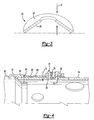
- Figure 4 is a schematic cross-sectional view of an attachment between a metal section and a ceramic can.
- Figure 1 illustrates selected portions of an example combustion section 10 used, for example, in a gas turbine engine for an aircraft.
- the combustor section 10 of a gas turbine engine includes an air fuel mixer 12 that supplies a mixture of air and fuel to an igniter 14.
- the air fuel mixer 12 and the igniter 14 are received in a metal section 16.
- the metal section 16 is secured to a ceramic can 18, which receives the ignition products of the ignited fuel and air mixture.
- the ceramic can 18 directs the ignition products through a transition duct 20 and into a turbine section (not shown) of a gas turbine engine.
- a flame temperature distribution in the combustion section 10 is such that the front end near the igniter 14 has a relatively cool flame and the aft end near the ceramic can 18 and transition duct 20 has a relatively hot flame.
- Utilizing the metal section 16 near the relatively cooler flame and the ceramic can 18 near the relatively hotter flame provides the benefit of reducing undesirable carbon monoxide emissions produced in previously known combustor assemblies.
- carbon monoxide is produced during cooling of the ignition products in the combustion section 10.
- the ceramic material of the ceramic can 18 does not require as much cooling as a metal material. Since there is less cooling with the ceramic can 18, less carbon monoxide is produced compared to previously known combustor assemblies that utilize a metallic can.
- the ceramic material of the ceramic can 18 is less dense than metal and therefore reduces the weight of an aircraft utilizing a turbine jet engine with a ceramic can. Furthermore, utilizing the relatively inexpensive metal section 16 (compared to ceramic sections) near the cooler flame portion reduces the expense of the combustion section 10.
- Figure 2 shows an exploded view of selected portions of the combustion section 10.
- the metal section 16 includes a forward portion 30 and a circular portion 32 welded to the forward portion 30.
- the circular portion 32 has an axial slot 34 and tabs 68 that receive the ceramic can 18.
- a clamp 36 is received around the axial slot 34 and the tabs 68 to secure the metal section 16 and the ceramic can 18 together.
- the clamp 36 in this example includes first and second sections 38a and 38b that are secured together with bolts 40a and 40b and nuts 42a and 42b.
- the clamp 36 can be made of more than two sections.
- Springs 44 such as Bellville washers, are received onto the bolts 40a and 40b between the nuts 42a and 42b and flanges 43 of the second section 38b.
- the springs 44 maintain a tension on the bolts 40a and 40b to maintain a clamping force of the clamp 36 around the metal section 16 and ceramic can 18, as described below.
- the clamp 36 is relatively thin and narrow such that the clamp 36 elastically stretches when the clamping force is applied.
- the clamp 36 is made of a relatively low thermal expansion material for example one having a coefficient of thermal expansion between about 4 x 10 -6 /°F and about 6 x 10 -6 /°F.
- the clamp 36 is made of an alloy having a coefficient of thermal expansion that is approximately double that of the ceramic material forming the ceramic can 18. This provides the benefit of reducing some of the thermal expansion difference between the clamp 36 and the ceramic can 18 to maintain the clamping load.
- An aft end 46 of the ceramic can 18 is received through a support ring 48, which is secured at bosses 50a and 50b to the transition duct 20.
- the support ring 48 is relatively low stiffness compared to the ceramic can 18 and therefore introduces minimal thermal stress to the ceramic can 18 in a radial direction.
- a seal 52 such as a ceramic rope, is received between the ceramic can 18 and the support ring 48 to seal the combustion section 10 from the turbine section (not shown) of the aircraft.
- the fit between the support ring 48, seal 52, and the ceramic can 18 is relatively loose such that the support ring 48 and the seal 52 do not significantly constrain axial thermal expansion of the ceramic can 18 during high temperature operation.
- the springs 44 are domed and include an outer surface 54 and an inner surface 56.
- the springs 44 are made of a high temperature alloy, such as a nickel-based alloy.
- the springs 44 are compressed in the direction D into a nearly flat shape.
- the springs 44 are biased to spring back to the domed shape. In the flat shape, the bias of the springs 44 to the domed shape provides a tension on the bolts 40a and 40b.
- the springs 44 are stacked in parallel where the outer surfaces 54 of the springs 44 face in the same direction.
- the springs 44 can be stacked in series where the outer surfaces 54 of consecutive springs 44 face towards each other.
- Springs 44 stacked in parallel provide an increased tension on the bolts 40a and 40b, whereas springs 44 stacked in series provide greater deflection at a lower tension.
- the springs 44 are configured to deflect more upon tightening than an expected amount of thermal expansion difference between the clamp 36 and the ceramic can 18 to maintain a desired clamping load over a variety of temperature ranges. Given this description, one of ordinary skill will be able to recognize appropriate spring 44 configurations to meet their particular needs.
- the ceramic can 18 is received into the axial slot 34 between the circular portion 32 and the forward section 30.
- the annular section 32 is welded onto the forward section 30.
- the annular section 32 is machined from a solid annular ring and includes axial subslots 66 that receive the ceramic can 18.
- the axial subslots 66 provide compliance in a radial direction between the ceramic can 18 and the metal section 16. This helps to secure the metal section 16 and the ceramic can 18 together.
- the annular section 32 includes a plurality of tabs 68 that extend axially from the forward section 30 about the ceramic can 18.
- one of the tabs includes an opening 70 that corresponds to an opening 72 in the ceramic can 18 and to an opening 73 in the second section 38b of the clamp 36.
- a pin 74 is received through the openings 70, 72, and 73 to secure the ceramic can 18 and metal section 16 together and resist axial movement between them.
- the pin 74 is welded to the clamp 36 before assembly of the combustion section 10.
- the pin 74 is made of metal or metal alloy.
- the pin 74 includes a cooling passage 76 that allows air to flow through. The air internally cools the pin 74 and maintains the temperature of the fastener below a desirable operating temperature of the metal or alloy.
- a bushing 78 is received between the pin 74 and the opening 72 of the ceramic can 18.
- the bushing 78 evenly distributes stress between the pin 74 and the ceramic can 18 and prevents relatively large stress concentrations.
- a gasket 80 is received between the tabs 68 and the ceramic can 18. When the clamp 36 is tightened, the gasket 80 compresses in the radial direction.
- the springs 44, tabs 68, and gasket 80 deflect in the radial direction.
- Each acts as a spring to provide a tension bias on the clamp 36.
- the tabs 68 bend radially inward along the direction R in Figure 4 upon tightening the clamp 36 and tend to spring radially outward to provide the tension on the clamp 36.
- the gasket 80 compresses and tries to decompress, providing a tension in the radial direction on the tabs 68, which provides a bias tension on the clamp 36.
- the springs 44 deflect to provide a biasing tension on the clamp 36.
- the metal section 16 thermally expands more than the ceramic can 18.
- the clamp 36 which is also made of a metal material, also thermally expands more than the ceramic can 18.
- the clamping force decreases.
- the springs 44, gasket 80, and tabs 68 deflect by a combined amount in the radial direction that is greater than a radial thermal expansion difference between the metal section 16 and the ceramic can 18. This provides the benefit of maintaining a clamping force between the first and second sections 38a and 38b of the clamp 36.
- the metal parts thermally expand more than the ceramic part and the spring components (i.e., the tabs 68, gasket 80, and springs 44) offset the difference in thermal expansion to at least partially maintain the clamping force.
- the gasket 80 has a coefficient of thermal expansion which is greater than that of the clamp 36.
Landscapes
- Engineering & Computer Science (AREA)
- General Engineering & Computer Science (AREA)
- Mechanical Engineering (AREA)
- Chemical & Material Sciences (AREA)
- Combustion & Propulsion (AREA)
- Ceramic Engineering (AREA)
- Connection Of Plates (AREA)
- Gasket Seals (AREA)
Abstract
Description
- This invention relates combustion engines and, more particularly, to a combustor assembly having a unique attachment between a ceramic combustor can and a metal section.
- Conventional combustion engines, such as those used in aircraft, utilize a combustor to ignite a mixture of fuel and compressed air to propel the aircraft. To reduce undesirable emission products produced in combustion of the fuel and air mixture, it is desirable to reduce the temperature at which the fuel and air mixture bums. This requires a high percentage of air to be mixed with the fuel (i.e., a "lean" mixture). Such a lean mixture reduces the amount of air available to cool the combustor and increases the combustor temperature. For combustors made entirely of metal, the increase in temperature may exceed a desirable operating temperature of the metal.
- Ceramic materials provide excellent high temperature resistance and have been considered for use in combustors to resist the high temperatures. Disadvantageously, the coefficient of thermal expansion of ceramics is typically much lower than that of metals, which may lead to thermal stress between parts made of ceramic and parts made of metal during operation of the aircraft engine. Furthermore, the difference in coefficients of the thermal expansion between ceramic and metal renders typical joining methods, such as welding or bonding, ineffective.
- Accordingly, there is a need for a combustor assembly that provides and maintains a tight fit between a ceramic part and a metal part over a relatively wide temperature range.
- This invention is a combustor assembly including a unique attachment between a metal section and a ceramic section that accommodates a thermal expansion difference between the metal and the ceramic.
- An exemplary combustor assembly according to the present invention includes a metal section having an axial opening that receives the ceramic section. A clamp is received around the axial opening to secure the metal section and the ceramic section together. Tabs on the metal section, a gasket between the metal section and the ceramic section, and springs within the clamp deform in a radial direction to cooperatively offset the thermal expansion difference to maintain a clamping force.
- An example method of these securing thermally mis-matched sections together includes a step of elastically deforming at least two deformation members in a radial direction to cooperatively provide an amount of deformation that is greater than a thermal expansion difference in the radial direction between a metal and a ceramic section to maintain a securing force between the sections.
- The various features and advantages of this invention will become apparent to those skilled in the art from the following detailed description of the currently preferred embodiment. The drawings that accompany the detailed description can be briefly described as follows.
- Figure 1 is a perspective view of an example combustion section.
- Figure 2 is an exploded view of selected portions of the combustion section shown in Figure 1.
- Figure 3 is a cross-sectional view of an example spring washer.
- Figure 4 is a schematic cross-sectional view of an attachment between a metal section and a ceramic can.
- Figure 1 illustrates selected portions of an
example combustion section 10 used, for example, in a gas turbine engine for an aircraft. In this example, thecombustor section 10 of a gas turbine engine includes anair fuel mixer 12 that supplies a mixture of air and fuel to anigniter 14. Theair fuel mixer 12 and theigniter 14 are received in ametal section 16. Themetal section 16 is secured to aceramic can 18, which receives the ignition products of the ignited fuel and air mixture. The ceramic can 18 directs the ignition products through atransition duct 20 and into a turbine section (not shown) of a gas turbine engine. - A flame temperature distribution in the
combustion section 10 is such that the front end near theigniter 14 has a relatively cool flame and the aft end near the ceramic can 18 andtransition duct 20 has a relatively hot flame. Utilizing themetal section 16 near the relatively cooler flame and the ceramic can 18 near the relatively hotter flame provides the benefit of reducing undesirable carbon monoxide emissions produced in previously known combustor assemblies. In previously known combustor assemblies, carbon monoxide is produced during cooling of the ignition products in thecombustion section 10. In the illustrated example, the ceramic material of the ceramic can 18 does not require as much cooling as a metal material. Since there is less cooling with the ceramic can 18, less carbon monoxide is produced compared to previously known combustor assemblies that utilize a metallic can. Further, the ceramic material of the ceramic can 18 is less dense than metal and therefore reduces the weight of an aircraft utilizing a turbine jet engine with a ceramic can. Furthermore, utilizing the relatively inexpensive metal section 16 (compared to ceramic sections) near the cooler flame portion reduces the expense of thecombustion section 10. - Figure 2 shows an exploded view of selected portions of the
combustion section 10. Themetal section 16 includes aforward portion 30 and acircular portion 32 welded to theforward portion 30. Thecircular portion 32 has anaxial slot 34 andtabs 68 that receive theceramic can 18. - A
clamp 36 is received around theaxial slot 34 and thetabs 68 to secure themetal section 16 and the ceramic can 18 together. Theclamp 36 in this example includes first andsecond sections bolts nuts clamp 36 can be made of more than two sections. Springs 44, such as Bellville washers, are received onto thebolts nuts flanges 43 of thesecond section 38b. Thesprings 44 maintain a tension on thebolts clamp 36 around themetal section 16 and ceramic can 18, as described below. Preferably, theclamp 36 is relatively thin and narrow such that theclamp 36 elastically stretches when the clamping force is applied. - Optionally, the
clamp 36 is made of a relatively low thermal expansion material for example one having a coefficient of thermal expansion between about 4 x 10⁻⁶/°F and about 6 x 10⁻⁶/°F. In one example, theclamp 36 is made of an alloy having a coefficient of thermal expansion that is approximately double that of the ceramic material forming theceramic can 18. This provides the benefit of reducing some of the thermal expansion difference between theclamp 36 and the ceramic can 18 to maintain the clamping load. - An
aft end 46 of the ceramic can 18 is received through asupport ring 48, which is secured atbosses transition duct 20. Thesupport ring 48 is relatively low stiffness compared to the ceramic can 18 and therefore introduces minimal thermal stress to the ceramic can 18 in a radial direction. - A
seal 52, such as a ceramic rope, is received between the ceramic can 18 and thesupport ring 48 to seal thecombustion section 10 from the turbine section (not shown) of the aircraft. The fit between thesupport ring 48,seal 52, and the ceramic can 18 is relatively loose such that thesupport ring 48 and theseal 52 do not significantly constrain axial thermal expansion of the ceramic can 18 during high temperature operation. - Referring to Figure 3, the
springs 44 are domed and include anouter surface 54 and aninner surface 56. Preferably, thesprings 44 are made of a high temperature alloy, such as a nickel-based alloy. When thebolts respective nuts springs 44 are compressed in the direction D into a nearly flat shape. As is known, thesprings 44 are biased to spring back to the domed shape. In the flat shape, the bias of thesprings 44 to the domed shape provides a tension on thebolts - The
springs 44 are stacked in parallel where theouter surfaces 54 of thesprings 44 face in the same direction. Alternatively, thesprings 44 can be stacked in series where theouter surfaces 54 ofconsecutive springs 44 face towards each other.Springs 44 stacked in parallel provide an increased tension on thebolts springs 44 stacked in series provide greater deflection at a lower tension. Preferably, thesprings 44 are configured to deflect more upon tightening than an expected amount of thermal expansion difference between theclamp 36 and the ceramic can 18 to maintain a desired clamping load over a variety of temperature ranges. Given this description, one of ordinary skill will be able to recognizeappropriate spring 44 configurations to meet their particular needs. - Referring to Figure 4, the ceramic can 18 is received into the
axial slot 34 between thecircular portion 32 and theforward section 30. Theannular section 32 is welded onto theforward section 30. In one example, theannular section 32 is machined from a solid annular ring and includesaxial subslots 66 that receive the ceramic can 18. Theaxial subslots 66 provide compliance in a radial direction between theceramic can 18 and themetal section 16. This helps to secure themetal section 16 and the ceramic can 18 together. - The
annular section 32 includes a plurality oftabs 68 that extend axially from theforward section 30 about theceramic can 18. In the illustrated example, one of the tabs includes anopening 70 that corresponds to anopening 72 in theceramic can 18 and to anopening 73 in thesecond section 38b of theclamp 36. Apin 74 is received through theopenings ceramic can 18 andmetal section 16 together and resist axial movement between them. Preferably, thepin 74 is welded to theclamp 36 before assembly of thecombustion section 10. - Preferably, the
pin 74 is made of metal or metal alloy. Thepin 74 includes acooling passage 76 that allows air to flow through. The air internally cools thepin 74 and maintains the temperature of the fastener below a desirable operating temperature of the metal or alloy. - A
bushing 78 is received between thepin 74 and theopening 72 of theceramic can 18. Thebushing 78 evenly distributes stress between thepin 74 and theceramic can 18 and prevents relatively large stress concentrations. - A
gasket 80 is received between thetabs 68 and theceramic can 18. When theclamp 36 is tightened, thegasket 80 compresses in the radial direction. - When the
clamp 36 is tightened around themetal section 16 and theceramic can 18, thesprings 44,tabs 68, andgasket 80 deflect in the radial direction. Each acts as a spring to provide a tension bias on theclamp 36. Thetabs 68 bend radially inward along the direction R in Figure 4 upon tightening theclamp 36 and tend to spring radially outward to provide the tension on theclamp 36. Thegasket 80 compresses and tries to decompress, providing a tension in the radial direction on thetabs 68, which provides a bias tension on theclamp 36. Thesprings 44 deflect to provide a biasing tension on theclamp 36. - During operation at a relatively high temperature, the
metal section 16 thermally expands more than theceramic can 18. Theclamp 36, which is also made of a metal material, also thermally expands more than theceramic can 18. As themetal section 16 and clamp 36 thermally expand, the clamping force decreases. In the illustrated example, thesprings 44,gasket 80, andtabs 68 deflect by a combined amount in the radial direction that is greater than a radial thermal expansion difference between themetal section 16 and theceramic can 18. This provides the benefit of maintaining a clamping force between the first andsecond sections clamp 36. That is, the metal parts thermally expand more than the ceramic part and the spring components (i.e., thetabs 68,gasket 80, and springs 44) offset the difference in thermal expansion to at least partially maintain the clamping force. Preferably thegasket 80 has a coefficient of thermal expansion which is greater than that of theclamp 36. - Although a preferred embodiment of this invention has been disclosed, a worker of ordinary skill in this art would recognize that certain modifications would come within the scope of this invention. For that reason, the following claims should be studied to determine the true scope and content of this invention.
Claims (22)
- A combustor assembly (10) comprising:a metal section (16) defining an axis and including an axial slot (34); anda ceramic section (18) received into the axial slot (34).
- The assembly as recited in Claim 1, wherein the metal section (16) includes a first diameter section (30) and a second diameter section (32) that is less than the first diameter section (30), the axial slot (34) being between the second diameter section (32) and tabs (68) extending axially from the first diameter section (30).
- The assembly as recited in Claim 2, wherein the annular section includes an axial sub-slot (66) that receives the ceramic section.
- The assembly as recited in Claim 2 or 3, wherein the tabs (68) are elastically deformable in a radial direction.
- The assembly as recited in Claim 2, 3 or 4, wherein at least one of the tabs (68) includes a tab opening (70) that corresponds to an opening (72) in the ceramic section (18).
- The assembly as recited in any of Claims 2 to 5, further comprising a gasket (80) between the tabs and the ceramic section.
- The assembly as recited in any preceding claim, further comprising a clamp (36) about the axial slot (34).
- The assembly as recited in any preceding claim, further comprising a support ring (48) secured to an exit duct, the support ring (48) receiving the ceramic section (18) therethrough, and a ceramic seal (52) between the support ring (48) and the ceramic section (18).
- A combustor assembly (10) comprising:a metal section (16);a ceramic section (18); anda clamp (36) received about a perimeter of the metal section (16) and the ceramic section (18) to secure the metal section (16) and the ceramic section (18) together.
- The assembly as recited in Claim 9, wherein the metal section (16) defines a longitudinal axis and the clamp (36) provides a securing force in a radial direction.
- The assembly as recited in Claim 9 or 10, further comprising a fastener (74) received through the clamp (36), metal section (16), and ceramic section (18) to resist relative axial and circumferential movement.
- The assembly as recited in Claim 11, further comprising a gasket (80) between the fastener (74) and at least the ceramic section (18).
- The assembly as recited in Claim 11 or 12, wherein the fastener (74) includes an internal cooling passage (76).
- The assembly as recited in any of Claims 9 to 13, wherein the clamp (36) includes at least a first section (38a) and a second section (38b) secured together with a threaded fastener (40a, 40b) and a nut (42a, 42b).
- The assembly as recited in Claim 14, further comprising at least one spring (44) between the threaded fastener (40a, 40b) and the nut (42a, 42b).
- The assembly as recited in Claim 15, further comprising a plurality of springs (44) between the threaded fastener (40a, 40b) and the nut (42a, 42b).
- The assembly as recited in any of Claims 9 to 16, further comprising a spring gasket (80) between the metal section (16) and the ceramic section (18).
- The assembly as recited in Claim 17, wherein the clamp (36) is made of a first material having a first coefficient of thermal expansion between about 4 x 10⁻⁶/°F and about 6 x 10⁻⁶/°F.
- The assembly as recited in Claim 18, wherein the spring gasket (80) is made of a second material having a second coefficient of thermal expansion that is greater than the first coefficient of thermal expansion.
- The assembly as recited in any of Claims 9 to 19, wherein the metal section (16) includes an axial slot (34) that receives the ceramic section (18) and the clamp (36) is received about the axial slot (34).
- A method of securing thermally mismatched sections (16, 18) together, comprising:elastically deforming at least two deformation members in a radial direction to cooperatively provide an amount of deformation that is greater than a thermal expansion difference in the radial direction between first and second sections to at least partially maintain a securing force between the first and second sections.
- The method as recited in Claim 19, including elastically deforming a gasket (80), a spring (44), and an axially extending tab (68) on one of the first and second sections (16, 18).
Applications Claiming Priority (1)
| Application Number | Priority Date | Filing Date | Title |
|---|---|---|---|
| US11/254,876 US7762076B2 (en) | 2005-10-20 | 2005-10-20 | Attachment of a ceramic combustor can |
Publications (3)
| Publication Number | Publication Date |
|---|---|
| EP1777461A2 true EP1777461A2 (en) | 2007-04-25 |
| EP1777461A3 EP1777461A3 (en) | 2010-08-25 |
| EP1777461B1 EP1777461B1 (en) | 2019-11-13 |
Family
ID=37667315
Family Applications (1)
| Application Number | Title | Priority Date | Filing Date |
|---|---|---|---|
| EP06254208.9A Expired - Fee Related EP1777461B1 (en) | 2005-10-20 | 2006-08-10 | Attachement of a ceramic combustor can |
Country Status (3)
| Country | Link |
|---|---|
| US (1) | US7762076B2 (en) |
| EP (1) | EP1777461B1 (en) |
| JP (1) | JP2007113906A (en) |
Cited By (5)
| Publication number | Priority date | Publication date | Assignee | Title |
|---|---|---|---|---|
| EP3139094A1 (en) * | 2015-09-02 | 2017-03-08 | General Electric Company | Combuster assembly for a turbine engine |
| US9976746B2 (en) | 2015-09-02 | 2018-05-22 | General Electric Company | Combustor assembly for a turbine engine |
| US10197278B2 (en) | 2015-09-02 | 2019-02-05 | General Electric Company | Combustor assembly for a turbine engine |
| US11149646B2 (en) | 2015-09-02 | 2021-10-19 | General Electric Company | Piston ring assembly for a turbine engine |
| US11402097B2 (en) | 2018-01-03 | 2022-08-02 | General Electric Company | Combustor assembly for a turbine engine |
Families Citing this family (16)
| Publication number | Priority date | Publication date | Assignee | Title |
|---|---|---|---|---|
| FR2903171B1 (en) * | 2006-06-29 | 2008-10-17 | Snecma Sa | CRABOT LINK ARRANGEMENT FOR TURBOMACHINE COMBUSTION CHAMBER |
| US7771160B2 (en) * | 2006-08-10 | 2010-08-10 | United Technologies Corporation | Ceramic shroud assembly |
| US7665960B2 (en) | 2006-08-10 | 2010-02-23 | United Technologies Corporation | Turbine shroud thermal distortion control |
| US8726675B2 (en) * | 2007-09-07 | 2014-05-20 | The Boeing Company | Scalloped flexure ring |
| US9127565B2 (en) * | 2008-04-16 | 2015-09-08 | Siemens Energy, Inc. | Apparatus comprising a CMC-comprising body and compliant porous element preloaded within an outer metal shell |
| US8167546B2 (en) * | 2009-09-01 | 2012-05-01 | United Technologies Corporation | Ceramic turbine shroud support |
| US10564944B2 (en) * | 2010-01-07 | 2020-02-18 | Microsoft Technology Licensing, Llc | Efficient immutable syntax representation with incremental change |
| DE102011016917A1 (en) | 2011-04-13 | 2012-10-18 | Rolls-Royce Deutschland Ltd & Co Kg | Gas turbine combustor with a holder of a seal for an attachment |
| US9822650B2 (en) | 2011-04-28 | 2017-11-21 | Hamilton Sundstrand Corporation | Turbomachine shroud |
| JP6053948B2 (en) * | 2013-10-24 | 2016-12-27 | 三菱電機株式会社 | Information processing apparatus, information processing method, and program |
| US9932831B2 (en) | 2014-05-09 | 2018-04-03 | United Technologies Corporation | High temperature compliant metallic elements for low contact stress ceramic support |
| US9771813B2 (en) * | 2014-06-26 | 2017-09-26 | Siemens Energy, Inc. | Converging flow joint insert system at an intersection between adjacent transitions extending between a combustor and a turbine assembly in a gas turbine engine |
| CN104450498B (en) * | 2014-12-16 | 2017-01-18 | 嘉兴凯实生物科技有限公司 | Nucleic acid extractor |
| US10634349B2 (en) * | 2015-08-24 | 2020-04-28 | General Electric Company | Wear pad system for turbine combustion systems and method for coupling wear pad into turbine combustion system |
| US9810434B2 (en) * | 2016-01-21 | 2017-11-07 | Siemens Energy, Inc. | Transition duct system with arcuate ceramic liner for delivering hot-temperature gases in a combustion turbine engine |
| KR102072101B1 (en) * | 2017-10-30 | 2020-01-31 | 두산중공업 주식회사 | Fuel nozzle module assembly and gas turbine having the same |
Citations (10)
| Publication number | Priority date | Publication date | Assignee | Title |
|---|---|---|---|---|
| GB843229A (en) * | 1958-02-24 | 1960-08-04 | Scottish Agricultural Ind Ltd | Improvements in tube couplers |
| FR1576375A (en) * | 1968-01-22 | 1969-08-01 | ||
| FR2384950A1 (en) * | 1977-03-26 | 1978-10-20 | Mtu Muenchen Gmbh | Insulated combustor for gas turbine - has floating ceramic tube between flame pipe and downstream intermediate section |
| JPS5659131A (en) * | 1979-10-19 | 1981-05-22 | Nissan Motor Co Ltd | Gas turbine combustor |
| DE19526924A1 (en) * | 1995-07-24 | 1997-05-22 | Bayer Ag | Ceramic-metal joint formed by casting metal on to ceramic and generating reduced thermal stresses |
| JPH10103674A (en) * | 1996-09-30 | 1998-04-21 | Nissan Motor Co Ltd | Combustor for gas turbine |
| EP1148300A1 (en) * | 2000-04-21 | 2001-10-24 | Kawasaki Jukogyo Kabushiki Kaisha | Ceramic member support structure for gas turbine |
| EP1152191A2 (en) * | 2000-05-05 | 2001-11-07 | General Electric Company | Combustor having a ceramic matrix composite liner |
| FR2825782A1 (en) * | 2001-06-06 | 2002-12-13 | Snecma Moteurs | Turbine with metal casing has composition combustion chamber fitted with sliding coupling to allow for differences in expansion coefficients |
| WO2006055169A1 (en) * | 2004-11-18 | 2006-05-26 | Siemens Power Generation, Inc. | Attachment system for ceramic combustor liner |
Family Cites Families (11)
| Publication number | Priority date | Publication date | Assignee | Title |
|---|---|---|---|---|
| US2839894A (en) * | 1952-12-31 | 1958-06-24 | Gen Motors Corp | Supporting arrangement for a gas turbine combustion chamber |
| US3999376A (en) * | 1973-07-05 | 1976-12-28 | Ford Motor Company | One-piece ceramic support housing for a gas turbine with a rotary regenerator |
| CA1034509A (en) * | 1975-10-14 | 1978-07-11 | John Korta | Vane rotator assembly for a gas turbine |
| US4363208A (en) * | 1980-11-10 | 1982-12-14 | General Motors Corporation | Ceramic combustor mounting |
| US4573320A (en) * | 1985-05-03 | 1986-03-04 | Mechanical Technology Incorporated | Combustion system |
| US5392596A (en) * | 1993-12-21 | 1995-02-28 | Solar Turbines Incorporated | Combustor assembly construction |
| JPH08312962A (en) * | 1995-05-16 | 1996-11-26 | Nissan Motor Co Ltd | Combustor for gas turbine |
| US6200092B1 (en) * | 1999-09-24 | 2001-03-13 | General Electric Company | Ceramic turbine nozzle |
| FR2825786B1 (en) * | 2001-06-06 | 2003-10-17 | Snecma Moteurs | FIXING METAL CAPS ON TURBOMACHINE CMC COMBUSTION CHAMBER WALLS |
| US6996976B2 (en) * | 2002-04-03 | 2006-02-14 | Cleaire Advanced Emmision Controls | Apparatus and method for mounting a device to a pipe |
| ITMI20031673A1 (en) * | 2003-08-28 | 2005-02-28 | Nuovo Pignone Spa | FIXING SYSTEM OF A FLAME TUBE OR "LINER". |
-
2005
- 2005-10-20 US US11/254,876 patent/US7762076B2/en active Active
-
2006
- 2006-08-10 EP EP06254208.9A patent/EP1777461B1/en not_active Expired - Fee Related
- 2006-08-11 JP JP2006219114A patent/JP2007113906A/en active Pending
Patent Citations (10)
| Publication number | Priority date | Publication date | Assignee | Title |
|---|---|---|---|---|
| GB843229A (en) * | 1958-02-24 | 1960-08-04 | Scottish Agricultural Ind Ltd | Improvements in tube couplers |
| FR1576375A (en) * | 1968-01-22 | 1969-08-01 | ||
| FR2384950A1 (en) * | 1977-03-26 | 1978-10-20 | Mtu Muenchen Gmbh | Insulated combustor for gas turbine - has floating ceramic tube between flame pipe and downstream intermediate section |
| JPS5659131A (en) * | 1979-10-19 | 1981-05-22 | Nissan Motor Co Ltd | Gas turbine combustor |
| DE19526924A1 (en) * | 1995-07-24 | 1997-05-22 | Bayer Ag | Ceramic-metal joint formed by casting metal on to ceramic and generating reduced thermal stresses |
| JPH10103674A (en) * | 1996-09-30 | 1998-04-21 | Nissan Motor Co Ltd | Combustor for gas turbine |
| EP1148300A1 (en) * | 2000-04-21 | 2001-10-24 | Kawasaki Jukogyo Kabushiki Kaisha | Ceramic member support structure for gas turbine |
| EP1152191A2 (en) * | 2000-05-05 | 2001-11-07 | General Electric Company | Combustor having a ceramic matrix composite liner |
| FR2825782A1 (en) * | 2001-06-06 | 2002-12-13 | Snecma Moteurs | Turbine with metal casing has composition combustion chamber fitted with sliding coupling to allow for differences in expansion coefficients |
| WO2006055169A1 (en) * | 2004-11-18 | 2006-05-26 | Siemens Power Generation, Inc. | Attachment system for ceramic combustor liner |
Cited By (7)
| Publication number | Priority date | Publication date | Assignee | Title |
|---|---|---|---|---|
| EP3139094A1 (en) * | 2015-09-02 | 2017-03-08 | General Electric Company | Combuster assembly for a turbine engine |
| US9976746B2 (en) | 2015-09-02 | 2018-05-22 | General Electric Company | Combustor assembly for a turbine engine |
| US10168051B2 (en) | 2015-09-02 | 2019-01-01 | General Electric Company | Combustor assembly for a turbine engine |
| US10197278B2 (en) | 2015-09-02 | 2019-02-05 | General Electric Company | Combustor assembly for a turbine engine |
| US11149646B2 (en) | 2015-09-02 | 2021-10-19 | General Electric Company | Piston ring assembly for a turbine engine |
| US11898494B2 (en) | 2015-09-02 | 2024-02-13 | General Electric Company | Piston ring assembly for a turbine engine |
| US11402097B2 (en) | 2018-01-03 | 2022-08-02 | General Electric Company | Combustor assembly for a turbine engine |
Also Published As
| Publication number | Publication date |
|---|---|
| EP1777461A3 (en) | 2010-08-25 |
| EP1777461B1 (en) | 2019-11-13 |
| US20080010990A1 (en) | 2008-01-17 |
| JP2007113906A (en) | 2007-05-10 |
| US7762076B2 (en) | 2010-07-27 |
Similar Documents
| Publication | Publication Date | Title |
|---|---|---|
| EP1777461B1 (en) | Attachement of a ceramic combustor can | |
| US8863528B2 (en) | Ceramic combustor can for a gas turbine engine | |
| US7849696B2 (en) | Assembling an annular combustion chamber of a turbomachine | |
| US8141370B2 (en) | Methods and apparatus for radially compliant component mounting | |
| JP4559796B2 (en) | Combustor dome assembly of a gas turbine engine with a free floating swirler | |
| US6148604A (en) | Combustion chamber assembly having a transition duct damping member | |
| US6708495B2 (en) | Fastening a CMC combustion chamber in a turbomachine using brazed tabs | |
| US6675585B2 (en) | Connection for a two-part CMC chamber | |
| US5291733A (en) | Liner mounting assembly | |
| US7237389B2 (en) | Attachment system for ceramic combustor liner | |
| US5392596A (en) | Combustor assembly construction | |
| JP3600911B2 (en) | Liner support structure for annular combustor | |
| US20100101232A1 (en) | Compliant metal support for ceramic combustor liner in a gas turbine engine | |
| US20030046940A1 (en) | Seal structure for combustor liner | |
| US7856826B2 (en) | Combustor dome mixer retaining means | |
| US5609031A (en) | Combustor assembly | |
| US20230112117A1 (en) | Combustor swirler to pseudo-dome attachment and interface with a cmc dome | |
| EP3760927A1 (en) | Combustor floating collar mounting arrangement | |
| US11828466B2 (en) | Combustor swirler to CMC dome attachment | |
| WO2023243734A1 (en) | Gas turbine combustor | |
| US20230112757A1 (en) | Combustor swirler to dome attachment | |
| CN105465832B (en) | Burner arrangement with fastening system for burner components |
Legal Events
| Date | Code | Title | Description |
|---|---|---|---|
| PUAI | Public reference made under article 153(3) epc to a published international application that has entered the european phase |
Free format text: ORIGINAL CODE: 0009012 |
|
| AK | Designated contracting states |
Kind code of ref document: A2 Designated state(s): AT BE BG CH CY CZ DE DK EE ES FI FR GB GR HU IE IS IT LI LT LU LV MC NL PL PT RO SE SI SK TR |
|
| AX | Request for extension of the european patent |
Extension state: AL BA HR MK YU |
|
| PUAL | Search report despatched |
Free format text: ORIGINAL CODE: 0009013 |
|
| AK | Designated contracting states |
Kind code of ref document: A3 Designated state(s): AT BE BG CH CY CZ DE DK EE ES FI FR GB GR HU IE IS IT LI LT LU LV MC NL PL PT RO SE SI SK TR |
|
| AX | Request for extension of the european patent |
Extension state: AL BA HR MK RS |
|
| RIC1 | Information provided on ipc code assigned before grant |
Ipc: F23R 3/00 20060101ALI20100722BHEP Ipc: F23R 3/60 20060101AFI20070126BHEP Ipc: F16L 49/04 20060101ALI20100722BHEP |
|
| 17P | Request for examination filed |
Effective date: 20110225 |
|
| AKX | Designation fees paid |
Designated state(s): DE GB |
|
| 17Q | First examination report despatched |
Effective date: 20150217 |
|
| RAP1 | Party data changed (applicant data changed or rights of an application transferred) |
Owner name: UNITED TECHNOLOGIES CORPORATION |
|
| STAA | Information on the status of an ep patent application or granted ep patent |
Free format text: STATUS: EXAMINATION IS IN PROGRESS |
|
| GRAP | Despatch of communication of intention to grant a patent |
Free format text: ORIGINAL CODE: EPIDOSNIGR1 |
|
| STAA | Information on the status of an ep patent application or granted ep patent |
Free format text: STATUS: GRANT OF PATENT IS INTENDED |
|
| INTG | Intention to grant announced |
Effective date: 20190103 |
|
| GRAJ | Information related to disapproval of communication of intention to grant by the applicant or resumption of examination proceedings by the epo deleted |
Free format text: ORIGINAL CODE: EPIDOSDIGR1 |
|
| STAA | Information on the status of an ep patent application or granted ep patent |
Free format text: STATUS: EXAMINATION IS IN PROGRESS |
|
| GRAP | Despatch of communication of intention to grant a patent |
Free format text: ORIGINAL CODE: EPIDOSNIGR1 |
|
| STAA | Information on the status of an ep patent application or granted ep patent |
Free format text: STATUS: GRANT OF PATENT IS INTENDED |
|
| INTG | Intention to grant announced |
Effective date: 20190524 |
|
| GRAS | Grant fee paid |
Free format text: ORIGINAL CODE: EPIDOSNIGR3 |
|
| GRAA | (expected) grant |
Free format text: ORIGINAL CODE: 0009210 |
|
| STAA | Information on the status of an ep patent application or granted ep patent |
Free format text: STATUS: THE PATENT HAS BEEN GRANTED |
|
| AK | Designated contracting states |
Kind code of ref document: B1 Designated state(s): DE GB |
|
| REG | Reference to a national code |
Ref country code: GB Ref legal event code: FG4D |
|
| REG | Reference to a national code |
Ref country code: DE Ref legal event code: R096 Ref document number: 602006058807 Country of ref document: DE |
|
| REG | Reference to a national code |
Ref country code: DE Ref legal event code: R097 Ref document number: 602006058807 Country of ref document: DE |
|
| PLBE | No opposition filed within time limit |
Free format text: ORIGINAL CODE: 0009261 |
|
| STAA | Information on the status of an ep patent application or granted ep patent |
Free format text: STATUS: NO OPPOSITION FILED WITHIN TIME LIMIT |
|
| 26N | No opposition filed |
Effective date: 20200814 |
|
| REG | Reference to a national code |
Ref country code: DE Ref legal event code: R119 Ref document number: 602006058807 Country of ref document: DE |
|
| GBPC | Gb: european patent ceased through non-payment of renewal fee |
Effective date: 20200810 |
|
| PG25 | Lapsed in a contracting state [announced via postgrant information from national office to epo] |
Ref country code: DE Free format text: LAPSE BECAUSE OF NON-PAYMENT OF DUE FEES Effective date: 20210302 |
|
| PG25 | Lapsed in a contracting state [announced via postgrant information from national office to epo] |
Ref country code: GB Free format text: LAPSE BECAUSE OF NON-PAYMENT OF DUE FEES Effective date: 20200810 |