EP1777137A1 - Improved base frame for a nestable roll container - Google Patents
Improved base frame for a nestable roll container Download PDFInfo
- Publication number
- EP1777137A1 EP1777137A1 EP06021848A EP06021848A EP1777137A1 EP 1777137 A1 EP1777137 A1 EP 1777137A1 EP 06021848 A EP06021848 A EP 06021848A EP 06021848 A EP06021848 A EP 06021848A EP 1777137 A1 EP1777137 A1 EP 1777137A1
- Authority
- EP
- European Patent Office
- Prior art keywords
- base frame
- base
- base panel
- legs
- wheels
- Prior art date
- Legal status (The legal status is an assumption and is not a legal conclusion. Google has not performed a legal analysis and makes no representation as to the accuracy of the status listed.)
- Granted
Links
Images


Classifications
-
- B—PERFORMING OPERATIONS; TRANSPORTING
- B62—LAND VEHICLES FOR TRAVELLING OTHERWISE THAN ON RAILS
- B62B—HAND-PROPELLED VEHICLES, e.g. HAND CARTS OR PERAMBULATORS; SLEDGES
- B62B3/00—Hand carts having more than one axis carrying transport wheels; Steering devices therefor; Equipment therefor
- B62B3/14—Hand carts having more than one axis carrying transport wheels; Steering devices therefor; Equipment therefor characterised by provisions for nesting or stacking, e.g. shopping trolleys
- B62B3/18—Hand carts having more than one axis carrying transport wheels; Steering devices therefor; Equipment therefor characterised by provisions for nesting or stacking, e.g. shopping trolleys nestable by means of pivoted supports or support parts, e.g. baskets
- B62B3/184—Nestable roll containers
- B62B3/186—V-shaped when nested
-
- B—PERFORMING OPERATIONS; TRANSPORTING
- B62—LAND VEHICLES FOR TRAVELLING OTHERWISE THAN ON RAILS
- B62B—HAND-PROPELLED VEHICLES, e.g. HAND CARTS OR PERAMBULATORS; SLEDGES
- B62B2205/00—Hand-propelled vehicles or sledges being foldable or dismountable when not in use
- B62B2205/003—Hand-propelled vehicles or sledges being foldable or dismountable when not in use with actuation mechanisms which drive the folding or unfolding operation
-
- B—PERFORMING OPERATIONS; TRANSPORTING
- B62—LAND VEHICLES FOR TRAVELLING OTHERWISE THAN ON RAILS
- B62B—HAND-PROPELLED VEHICLES, e.g. HAND CARTS OR PERAMBULATORS; SLEDGES
- B62B2301/00—Wheel arrangements; Steering; Stability; Wheel suspension
- B62B2301/04—Wheel arrangements; Steering; Stability; Wheel suspension comprising a wheel pivotable about a substantially vertical axis, e.g. swivelling castors
- B62B2301/046—Wheel arrangements; Steering; Stability; Wheel suspension comprising a wheel pivotable about a substantially vertical axis, e.g. swivelling castors with means restricting the rotation about that axis
- B62B2301/0463—Wheel arrangements; Steering; Stability; Wheel suspension comprising a wheel pivotable about a substantially vertical axis, e.g. swivelling castors with means restricting the rotation about that axis by blocking the rotation at a position
Definitions
- the present invention relates to a base frame for a roll container, which base frame is generally U-shaped and is provided with two legs which are connected pivotally to a transverse connection; a plurality of wheels mounted on the underside of the base frame; means for fastening one or more panels, which means are situated on the upper side of the base frame; and a base panel which is mounted in upward foldable manner on the base frame such that the legs are urged into a transport position when the base panel is folded down and the legs can take up a nesting position when the base panel is folded up.
- a roll container with a base frame of the type described in the preamble is known from the Netherlands patent NL 1025734 from the same applicant.
- the known roll container is intended for the transport of goods such as flowers and plants, often over great distances. After unloading of the goods the known roll container can be set easily and quickly in the nesting position by folding up the base panel.
- a set of nested, empty roll containers takes up minimal space and can therefore be transported at minimal cost.
- the invention has for its object to provide an improved base frame for a roll container of the type stated in the preamble.
- the base frame according to the invention has for this purpose the feature that the wheels comprise at least two swivel wheels; that the base panel and the base frame are provided with co-acting locking means for locking the swivel wheels, these locking means being adapted to lock the swivel wheels when the base panel is folded down and to unlock the swivel wheels when the base panel is folded up; and that the base panel engages by means of a toothing on the base frame, this toothing being adapted to urge the legs to the transport position when the base panel is folded down and to urge the legs to the nesting position when the base panel is folded up.
- the known roll container is in practice often provided with swivel wheels.
- the swivel wheels are locked in favourable manner against swivelling in the transport position of the base frame.
- the swivel wheels are advantageously unlocked in the nesting position of the base frame.
- the improved base frame is hereby always optimally ready for the intended use.
- the toothing provides a mechanically robust and reliable construction with which the legs are placed automatically in the correct position.
- the base frame according to the invention is fully ready for use in one operation.
- the locking means are adapted, when the base panel is folded down, to automatically lock the swivel wheels in transporting direction by displacing the base frame.
- the improved base frame is automatically in optimal readiness for the intended use.
- the base panel is provided on the underside thereof with one or more pins, and each swivel wheel is provided with a cap with an opening for receiving one of the pins.
- each swivel wheel is provided with a yoke plate with an opening for receiving one of the pins.
- the cap or yoke plate is provided with a chamfered portion close to the opening.
- the pins are preferably spring-mounted.
- the base panel is provided with further locking means for locking to the base frame in the transport position.
- the invention also relates to a roll container provided with a base frame according to the invention.
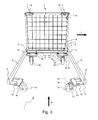
- FIG. 1 shows a schematic view of a first embodiment of a roll container 100 according to the invention.
- Roll container or rolling container 100 is provided with a base frame 1 according to the invention.
- Panels 101 are placed on base frame 1.
- panels 101 are substantially provided with rod mesh.
- Standard rod mesh sides are available on the market which can be mounted on base frame 1 in a manner known in the field.
- roll container 100 can further be provided with shelves (not shown).
- Base frame 1 is provided on the top side with a base panel 2.
- base panel 2 is likewise substantially provided with rod mesh. If desired, base panel 2 and/or panels 101 can take another form, for instance a closed form.
- Base panel 2 is provided on the underside with wheels 3, 4.
- Roll container 100 is shown in the transport mode or transport position, i.e. ready for displacement in transporting direction T.
- FIG. 2 shows base frame 1 in the transport position with folded-down base panel 2.
- Base frame 1 is generally U-shaped and has two legs 6 connected pivotally to a transverse connection 7. Legs 6 and transverse connection 7 are provided on the upper side with fastening means 8 for panels 101. Fastening means 8 are shown by way of illustration in the form of openings 8.
- Base frame 1 is provided with four wheels 3a, 3v, 4a, 4v. At least two of the wheels are swivel wheels, in this embodiment 3a, 3v.
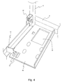
- Figure 3 shows base frame 1 in the nesting mode or nesting position with folded-up base panel 2. Legs 6 are now urged into the nesting position. In the nesting position legs 6 move apart sufficiently to allow nesting of a plurality of roll containers 100 with base frames 1.
- Base frame 1 and base panel 2 are provided with co-acting locking means 14, 15, 16, 18 for locking swivel wheels 3a, 3v.
- the locking means are adapted such that swivel wheels 3a, 3v are locked against swiveling when base panel 2 is folded down, and the swivel wheels are unlocked when base panel 2 is folded up.
- the locking means comprise a pin-hole connection consisting of a pin 14 arranged on base panel 2 and an opening 18 in a cap 16 mounted on yoke plate 17 of swivel wheel 3a, 3v.
- cap 16 can be integrated into yoke plate 17.
- the locking means are preferably given a self-locating form. This can be achieved by arranging opening 18 recessed into cap 16. Wheels 3a, 3v, 4a, 4v are mounted on support plates 9a, 9v arranged under legs 6. An opening 15 for passage of pin 14 is provided in each support plate. Pins 14 are preferably spring-mounted. Through folding down of the base panel pin 14 protrudes through opening 50. When base frame 1 is moved the swivel wheels 3a, 3v will automatically take up the intended transport position, whereby pin 14 can be received in opening 18. Swivel wheels 3a, 3v are now locked in the transport position and function as rigid casters.
- Base panel 2 is mounted rotatably on legs 6, for instance by means of pins 13.
- Base panel 2 is further provided with a toothing 11 which engages in slotted holes 12 on support plates 9a. In co-action with slotted holes 12 the toothing 11 provides for an active movement of legs 6 between the nesting position and the transport position.
- Base panel 2 is further provided on the underside with protrusions 19 which are intended to be received in slotted holes 10 arranged in support plates 9v for the purpose of locking base frame 1 in the transport position.
- locking means 5 are provided on base panel 2 for the purpose of locking base panel 2 to base frame 1 in the transport position.
- the locking means are embodied as handles 5 which engage on support plates 9v.
- Figure 4 shows a part of base frame 1 in more detail. Clearly shown is how toothing 11 engages in slotted holes 12 in order to actively move legs 6 to the desired position.
- Pin 14 which is intended to lock swivel wheel 3a (not shown here) so it functions as rigid caster, is shown in the preferred embodiment as spring-mounted pin.
Landscapes
- Engineering & Computer Science (AREA)
- Chemical & Material Sciences (AREA)
- Combustion & Propulsion (AREA)
- Transportation (AREA)
- Mechanical Engineering (AREA)
- Handcart (AREA)
Abstract
Description
- The present invention relates to a base frame for a roll container, which base frame is generally U-shaped and is provided with two legs which are connected pivotally to a transverse connection; a plurality of wheels mounted on the underside of the base frame; means for fastening one or more panels, which means are situated on the upper side of the base frame; and a base panel which is mounted in upward foldable manner on the base frame such that the legs are urged into a transport position when the base panel is folded down and the legs can take up a nesting position when the base panel is folded up.
- A roll container with a base frame of the type described in the preamble is known from the
Netherlands patent NL 1025734 - The invention has for its object to provide an improved base frame for a roll container of the type stated in the preamble.
- The base frame according to the invention has for this purpose the feature that the wheels comprise at least two swivel wheels; that the base panel and the base frame are provided with co-acting locking means for locking the swivel wheels, these locking means being adapted to lock the swivel wheels when the base panel is folded down and to unlock the swivel wheels when the base panel is folded up; and that the base panel engages by means of a toothing on the base frame, this toothing being adapted to urge the legs to the transport position when the base panel is folded down and to urge the legs to the nesting position when the base panel is folded up.
- Since the nesting direction, i.e. the direction in which the roll containers are nested, is substantially at right angles to the transporting direction, the known roll container is in practice often provided with swivel wheels. According to the invention the swivel wheels are locked in favourable manner against swivelling in the transport position of the base frame. Conversely, the swivel wheels are advantageously unlocked in the nesting position of the base frame. The improved base frame is hereby always optimally ready for the intended use. The toothing provides a mechanically robust and reliable construction with which the legs are placed automatically in the correct position. The base frame according to the invention is fully ready for use in one operation.
- In a first practical preferred embodiment, the locking means are adapted, when the base panel is folded down, to automatically lock the swivel wheels in transporting direction by displacing the base frame. By being taken into use the improved base frame is automatically in optimal readiness for the intended use.
- According to a first variant, the base panel is provided on the underside thereof with one or more pins, and each swivel wheel is provided with a cap with an opening for receiving one of the pins. According to a second variant, each swivel wheel is provided with a yoke plate with an opening for receiving one of the pins. In a self-locating embodiment the cap or yoke plate is provided with a chamfered portion close to the opening. The pins are preferably spring-mounted.
- According to another preferred embodiment, the base panel is provided with further locking means for locking to the base frame in the transport position.
- The invention also relates to a roll container provided with a base frame according to the invention.
- The invention will now be discussed in more detail with reference to the drawings, in which
- Figure 1 shows a schematic view of a first embodiment of a roll container according to the invention;
- Figure 2 shows a schematic view of the base frame of the roll container of figure 1 in transport position;
- Figure 3 shows a schematic view of the base frame of the roll container of figure 1 in nesting position; and
- Figure 4 shows part of the base frame of the roll container of figure 3 in more detail.
- The same components are designated in the figures with the same reference numerals.
- Figure 1 shows a schematic view of a first embodiment of a
roll container 100 according to the invention. Roll container orrolling container 100 is provided with abase frame 1 according to the invention.Panels 101 are placed onbase frame 1. In the shownpreferred embodiment panels 101 are substantially provided with rod mesh. Standard rod mesh sides are available on the market which can be mounted onbase frame 1 in a manner known in the field. If desired,roll container 100 can further be provided with shelves (not shown). -
Base frame 1 is provided on the top side with abase panel 2. In the shown preferredembodiment base panel 2 is likewise substantially provided with rod mesh. If desired,base panel 2 and/orpanels 101 can take another form, for instance a closed form.Base panel 2 is provided on the underside withwheels -
Roll container 100 is shown in the transport mode or transport position, i.e. ready for displacement in transporting direction T. - Figure 2 shows
base frame 1 in the transport position with folded-down base panel 2.Base frame 1 is generally U-shaped and has twolegs 6 connected pivotally to atransverse connection 7.Legs 6 andtransverse connection 7 are provided on the upper side with fastening means 8 forpanels 101. Fastening means 8 are shown by way of illustration in the form ofopenings 8. - In the shown position of
base frame 1 with folded-down base panel 2 thelegs 6 are urged into the transport position. -
Base frame 1 is provided with fourwheels embodiment - Figure 3 shows
base frame 1 in the nesting mode or nesting position with folded-upbase panel 2.Legs 6 are now urged into the nesting position. In thenesting position legs 6 move apart sufficiently to allow nesting of a plurality ofroll containers 100 withbase frames 1. -
Base frame 1 andbase panel 2 are provided with co-acting locking means 14, 15, 16, 18 for lockingswivel wheels swivel wheels base panel 2 is folded down, and the swivel wheels are unlocked whenbase panel 2 is folded up. - The locking means comprise a pin-hole connection consisting of a
pin 14 arranged onbase panel 2 and an opening 18 in acap 16 mounted onyoke plate 17 ofswivel wheel cap 16 can be integrated intoyoke plate 17. The locking means are preferably given a self-locating form. This can be achieved by arranging opening 18 recessed intocap 16.Wheels support plates legs 6. An opening 15 for passage ofpin 14 is provided in each support plate.Pins 14 are preferably spring-mounted. Through folding down of thebase panel pin 14 protrudes through opening 50. Whenbase frame 1 is moved theswivel wheels pin 14 can be received in opening 18.Swivel wheels -
Base panel 2 is mounted rotatably onlegs 6, for instance by means ofpins 13.Base panel 2 is further provided with atoothing 11 which engages in slottedholes 12 onsupport plates 9a. In co-action with slottedholes 12 thetoothing 11 provides for an active movement oflegs 6 between the nesting position and the transport position. -
Base panel 2 is further provided on the underside withprotrusions 19 which are intended to be received in slottedholes 10 arranged insupport plates 9v for the purpose of lockingbase frame 1 in the transport position. - Further locking means 5 are provided on
base panel 2 for the purpose of lockingbase panel 2 tobase frame 1 in the transport position. In the shown preferred embodiment the locking means are embodied ashandles 5 which engage onsupport plates 9v. - Figure 4 shows a part of
base frame 1 in more detail. Clearly shown is howtoothing 11 engages in slottedholes 12 in order to actively movelegs 6 to the desired position.Pin 14, which is intended to lockswivel wheel 3a (not shown here) so it functions as rigid caster, is shown in the preferred embodiment as spring-mounted pin. - The invention is of course not limited to the shown and described preferred embodiment, but extends generally to any embodiment falling within the scope of the appended claims as seen in the light of the foregoing description and drawings.
Claims (8)
- Base frame for a roll container, which base frame is generally U-shaped and provided with:- two legs which are connected pivotally to a transverse connection;- a plurality of wheels mounted on the underside of the base frame;- means for fastening one or more panels, which means are situated on the upper side of the base frame; and- a base panel which is mounted in upward foldable manner on the base frame such that the legs are urged into a transport position when the base panel is folded down and the legs can take up a nesting position when the base panel is folded up,characterized in that- the wheels comprise at least two swivel wheels (3a, 3v);- the base panel (2) and the base frame (1) are provided with co-acting locking means (14, 16, 18) for locking the swivel wheels, these locking means being adapted to lock the swivel wheels when the base panel is folded down and to unlock the swivel wheels when the base panel is folded up; and- the base panel (2) engages by means of a toothing (11) on the base frame (1), this toothing (11) being adapted to urge the legs (6) to the transport position when the base panel (2) is folded down and to urge the legs to the nesting position when the base panel is folded up.
- Base frame as claimed in claim 1, wherein the locking means (14, 16, 18) are adapted, when the base panel (2) is folded down, to automatically lock the swivel wheels (3a, 3v) in transporting direction (T) by displacing the base frame (1).
- Base frame as claimed in claim 1 or 2, wherein the base panel (2) is provided on the underside thereof with one or more pins (14), and wherein each swivel wheel (3a, 3v) is provided with a cap (16) with an opening (18) for receiving one of the pins.
- Base frame as claimed in claim 1 or 2, wherein the base panel (2) is provided on the underside thereof with one or more pins (14), and wherein each swivel wheel (3a, 3v) is provided with a yoke plate with an opening (18) for receiving one of the pins.
- Base frame as claimed in claim 3 or 4, wherein the cap (16) or the yoke plate is provided with a chamfered portion close to the opening (18).
- Base frame as claimed in claim 3 or 4, wherein the pins (14) are spring-mounted.
- Base frame as claimed in any of the foregoing claims, wherein the base panel (2) is provided with further locking means (5) for locking to the base frame (1) in the transport position.
- Roll container (100) provided with a base frame (1) as claimed in any of the foregoing claims.
Priority Applications (1)
| Application Number | Priority Date | Filing Date | Title |
|---|---|---|---|
| PL06021848T PL1777137T3 (en) | 2005-10-18 | 2006-10-18 | Improved base frame for a nestable roll container |
Applications Claiming Priority (1)
| Application Number | Priority Date | Filing Date | Title |
|---|---|---|---|
| NL1030215A NL1030215C2 (en) | 2005-10-18 | 2005-10-18 | Improved bottom frame for a nestable roll container. |
Publications (2)
| Publication Number | Publication Date |
|---|---|
| EP1777137A1 true EP1777137A1 (en) | 2007-04-25 |
| EP1777137B1 EP1777137B1 (en) | 2012-07-25 |
Family
ID=36685792
Family Applications (1)
| Application Number | Title | Priority Date | Filing Date |
|---|---|---|---|
| EP06021848A Not-in-force EP1777137B1 (en) | 2005-10-18 | 2006-10-18 | Improved base frame for a nestable roll container |
Country Status (3)
| Country | Link |
|---|---|
| EP (1) | EP1777137B1 (en) |
| NL (1) | NL1030215C2 (en) |
| PL (1) | PL1777137T3 (en) |
Cited By (5)
| Publication number | Priority date | Publication date | Assignee | Title |
|---|---|---|---|---|
| EP2014535A2 (en) | 2007-07-13 | 2009-01-14 | GEBHARDT Transport- und Lagersysteme GmbH | Stackable roller container |
| DE102007033147A1 (en) * | 2007-07-13 | 2009-01-22 | Gebhardt Transport- Und Lagersysteme Gmbh | Stackable rolling container for transportation of e.g. food, has base at which conveyor rollers and plug-on walls are arranged, where each wall includes end strut drawn-in opposite to plane and base strut arranged adjacent to end strut |
| DE202009016204U1 (en) | 2009-11-30 | 2010-03-04 | Gebhardt Transport- Und Lagersysteme Gmbh | Stackable roll container with shelves |
| EP2327601A2 (en) | 2009-11-30 | 2011-06-01 | GEBHARDT Transport- und Lagersysteme GmbH | Stackable roll container with insertable shelves |
| DE102009056363B3 (en) * | 2009-11-30 | 2011-06-16 | Gebhardt Transport- Und Lagersysteme Gmbh | Stackable roll container for transporting commodity e.g. food, in big bag, has connection rods designed as supporting rods, such that supporting rods serve as supporting unit and guiding unit for insertion base inserted between side walls |
Families Citing this family (1)
| Publication number | Priority date | Publication date | Assignee | Title |
|---|---|---|---|---|
| GB202213772D0 (en) * | 2022-09-21 | 2022-11-02 | Southgate Global Ltd | Item storage movement assembly with a movable base plate |
Citations (5)
| Publication number | Priority date | Publication date | Assignee | Title |
|---|---|---|---|---|
| US3861702A (en) | 1972-11-20 | 1975-01-21 | Banner Metals Inc | Transport cart |
| GB1569641A (en) | 1976-09-23 | 1980-06-18 | Sjoeblom A | Nestable pallet |
| EP1048546A1 (en) * | 1999-04-27 | 2000-11-02 | Fink, Jean R. | Device to open the sides of a roller-container at the same time |
| GB2353700A (en) * | 1999-09-02 | 2001-03-07 | Roll Containers Rental Ltd | Trolley with lockable castor wheels |
| NL1025734C1 (en) | 2004-03-16 | 2005-09-19 | Scholte S Metaalbewerking B V | Roller container for transporting e.g. flowers, has U shaped base frame with pivotally mounted collapsible arms |
-
2005
- 2005-10-18 NL NL1030215A patent/NL1030215C2/en not_active IP Right Cessation
-
2006
- 2006-10-18 EP EP06021848A patent/EP1777137B1/en not_active Not-in-force
- 2006-10-18 PL PL06021848T patent/PL1777137T3/en unknown
Patent Citations (5)
| Publication number | Priority date | Publication date | Assignee | Title |
|---|---|---|---|---|
| US3861702A (en) | 1972-11-20 | 1975-01-21 | Banner Metals Inc | Transport cart |
| GB1569641A (en) | 1976-09-23 | 1980-06-18 | Sjoeblom A | Nestable pallet |
| EP1048546A1 (en) * | 1999-04-27 | 2000-11-02 | Fink, Jean R. | Device to open the sides of a roller-container at the same time |
| GB2353700A (en) * | 1999-09-02 | 2001-03-07 | Roll Containers Rental Ltd | Trolley with lockable castor wheels |
| NL1025734C1 (en) | 2004-03-16 | 2005-09-19 | Scholte S Metaalbewerking B V | Roller container for transporting e.g. flowers, has U shaped base frame with pivotally mounted collapsible arms |
Cited By (9)
| Publication number | Priority date | Publication date | Assignee | Title |
|---|---|---|---|---|
| EP2014535A2 (en) | 2007-07-13 | 2009-01-14 | GEBHARDT Transport- und Lagersysteme GmbH | Stackable roller container |
| DE102007033147A1 (en) * | 2007-07-13 | 2009-01-22 | Gebhardt Transport- Und Lagersysteme Gmbh | Stackable rolling container for transportation of e.g. food, has base at which conveyor rollers and plug-on walls are arranged, where each wall includes end strut drawn-in opposite to plane and base strut arranged adjacent to end strut |
| DE102007033147B4 (en) * | 2007-07-13 | 2009-10-29 | Gebhardt Transport- Und Lagersysteme Gmbh | Stackable roll container |
| EP2014535A3 (en) * | 2007-07-13 | 2010-03-03 | GEBHARDT Transport- und Lagersysteme GmbH | Stackable roller container |
| US8025148B2 (en) | 2007-07-13 | 2011-09-27 | Gebhardt Transport-Und Lagersysteme Gmbh | Stackable roll containers |
| DE202009016204U1 (en) | 2009-11-30 | 2010-03-04 | Gebhardt Transport- Und Lagersysteme Gmbh | Stackable roll container with shelves |
| EP2327601A2 (en) | 2009-11-30 | 2011-06-01 | GEBHARDT Transport- und Lagersysteme GmbH | Stackable roll container with insertable shelves |
| DE102009056363B3 (en) * | 2009-11-30 | 2011-06-16 | Gebhardt Transport- Und Lagersysteme Gmbh | Stackable roll container for transporting commodity e.g. food, in big bag, has connection rods designed as supporting rods, such that supporting rods serve as supporting unit and guiding unit for insertion base inserted between side walls |
| US8505933B2 (en) | 2009-11-30 | 2013-08-13 | Gebhardt Transport- Und Lagersysteme Gmbh | Roll container with insert bases |
Also Published As
| Publication number | Publication date |
|---|---|
| NL1030215C2 (en) | 2007-04-19 |
| PL1777137T3 (en) | 2013-01-31 |
| EP1777137B1 (en) | 2012-07-25 |
Similar Documents
| Publication | Publication Date | Title |
|---|---|---|
| EP1777137B1 (en) | Improved base frame for a nestable roll container | |
| US8979100B2 (en) | Modular container assembly | |
| US9428205B2 (en) | Security cart | |
| US7025548B2 (en) | Transport carts configured to be locked to the sidewalls of a transportation vehicle for distributing product | |
| US8070181B2 (en) | Convertible cart | |
| US8353524B2 (en) | Wheeled cart slidable onto horizontal surface | |
| US20140238992A1 (en) | Shopping cart | |
| CA3009156C (en) | Cart and dolly handle with stacking position | |
| US20210039700A1 (en) | Personal shopping cart and method of use | |
| US6102645A (en) | Wheeled cargo transportation cart with dual self-aligning spring action loading ramps | |
| EP3397539B1 (en) | Cart and dolly handle with hinged middle beam | |
| EP2969701A2 (en) | Shopping cart | |
| JP4636993B2 (en) | Air cargo small container | |
| EP1818270B1 (en) | Large modular container with reduced storage volume | |
| CN101885343A (en) | Improved folding six-wheeled trolley structure | |
| GB2536268A (en) | Container | |
| EP2450017B1 (en) | Bed assembly method | |
| EP2813411B1 (en) | Roll container | |
| EP2650170A1 (en) | Trailer provided with a movable coupling beam | |
| AU708740B2 (en) | Goods handling/transfer apparatus | |
| CA2360007C (en) | Beverage distribution system and method of its manufacture and operation | |
| CA2887926C (en) | Security cart | |
| SU996248A1 (en) | Hand cart for unit loads | |
| JP2011235869A (en) | Carrier for storage | |
| US20080083765A1 (en) | Portable container for assembly at point of use |
Legal Events
| Date | Code | Title | Description |
|---|---|---|---|
| PUAI | Public reference made under article 153(3) epc to a published international application that has entered the european phase |
Free format text: ORIGINAL CODE: 0009012 |
|
| AK | Designated contracting states |
Kind code of ref document: A1 Designated state(s): AT BE BG CH CY CZ DE DK EE ES FI FR GB GR HU IE IS IT LI LT LU LV MC NL PL PT RO SE SI SK TR |
|
| AX | Request for extension of the european patent |
Extension state: AL BA HR MK YU |
|
| 17P | Request for examination filed |
Effective date: 20071023 |
|
| 17Q | First examination report despatched |
Effective date: 20071130 |
|
| AKX | Designation fees paid |
Designated state(s): AT BE BG CH CY CZ DE DK EE ES FI FR GB GR HU IE IS IT LI LT LU LV MC NL PL PT RO SE SI SK TR |
|
| GRAP | Despatch of communication of intention to grant a patent |
Free format text: ORIGINAL CODE: EPIDOSNIGR1 |
|
| GRAS | Grant fee paid |
Free format text: ORIGINAL CODE: EPIDOSNIGR3 |
|
| GRAA | (expected) grant |
Free format text: ORIGINAL CODE: 0009210 |
|
| AK | Designated contracting states |
Kind code of ref document: B1 Designated state(s): AT BE BG CH CY CZ DE DK EE ES FI FR GB GR HU IE IS IT LI LT LU LV MC NL PL PT RO SE SI SK TR |
|
| REG | Reference to a national code |
Ref country code: GB Ref legal event code: FG4D |
|
| REG | Reference to a national code |
Ref country code: CH Ref legal event code: EP |
|
| REG | Reference to a national code |
Ref country code: IE Ref legal event code: FG4D Ref country code: AT Ref legal event code: REF Ref document number: 567575 Country of ref document: AT Kind code of ref document: T Effective date: 20120815 |
|
| REG | Reference to a national code |
Ref country code: DE Ref legal event code: R096 Ref document number: 602006030919 Country of ref document: DE Effective date: 20120920 |
|
| REG | Reference to a national code |
Ref country code: CH Ref legal event code: NV Representative=s name: SCHNEIDER FELDMANN AG PATENT- UND MARKENANWAELTE |
|
| REG | Reference to a national code |
Ref country code: NL Ref legal event code: T3 |
|
| REG | Reference to a national code |
Ref country code: AT Ref legal event code: MK05 Ref document number: 567575 Country of ref document: AT Kind code of ref document: T Effective date: 20120725 |
|
| REG | Reference to a national code |
Ref country code: LT Ref legal event code: MG4D Effective date: 20120725 |
|
| PG25 | Lapsed in a contracting state [announced via postgrant information from national office to epo] |
Ref country code: CY Free format text: LAPSE BECAUSE OF FAILURE TO SUBMIT A TRANSLATION OF THE DESCRIPTION OR TO PAY THE FEE WITHIN THE PRESCRIBED TIME-LIMIT Effective date: 20120725 Ref country code: LT Free format text: LAPSE BECAUSE OF FAILURE TO SUBMIT A TRANSLATION OF THE DESCRIPTION OR TO PAY THE FEE WITHIN THE PRESCRIBED TIME-LIMIT Effective date: 20120725 Ref country code: FI Free format text: LAPSE BECAUSE OF FAILURE TO SUBMIT A TRANSLATION OF THE DESCRIPTION OR TO PAY THE FEE WITHIN THE PRESCRIBED TIME-LIMIT Effective date: 20120725 Ref country code: AT Free format text: LAPSE BECAUSE OF FAILURE TO SUBMIT A TRANSLATION OF THE DESCRIPTION OR TO PAY THE FEE WITHIN THE PRESCRIBED TIME-LIMIT Effective date: 20120725 Ref country code: IS Free format text: LAPSE BECAUSE OF FAILURE TO SUBMIT A TRANSLATION OF THE DESCRIPTION OR TO PAY THE FEE WITHIN THE PRESCRIBED TIME-LIMIT Effective date: 20121125 |
|
| REG | Reference to a national code |
Ref country code: PL Ref legal event code: T3 |
|
| PG25 | Lapsed in a contracting state [announced via postgrant information from national office to epo] |
Ref country code: LV Free format text: LAPSE BECAUSE OF FAILURE TO SUBMIT A TRANSLATION OF THE DESCRIPTION OR TO PAY THE FEE WITHIN THE PRESCRIBED TIME-LIMIT Effective date: 20120725 Ref country code: GR Free format text: LAPSE BECAUSE OF FAILURE TO SUBMIT A TRANSLATION OF THE DESCRIPTION OR TO PAY THE FEE WITHIN THE PRESCRIBED TIME-LIMIT Effective date: 20121026 Ref country code: SI Free format text: LAPSE BECAUSE OF FAILURE TO SUBMIT A TRANSLATION OF THE DESCRIPTION OR TO PAY THE FEE WITHIN THE PRESCRIBED TIME-LIMIT Effective date: 20120725 Ref country code: SE Free format text: LAPSE BECAUSE OF FAILURE TO SUBMIT A TRANSLATION OF THE DESCRIPTION OR TO PAY THE FEE WITHIN THE PRESCRIBED TIME-LIMIT Effective date: 20120725 Ref country code: PT Free format text: LAPSE BECAUSE OF FAILURE TO SUBMIT A TRANSLATION OF THE DESCRIPTION OR TO PAY THE FEE WITHIN THE PRESCRIBED TIME-LIMIT Effective date: 20121126 |
|
| PG25 | Lapsed in a contracting state [announced via postgrant information from national office to epo] |
Ref country code: ES Free format text: LAPSE BECAUSE OF FAILURE TO SUBMIT A TRANSLATION OF THE DESCRIPTION OR TO PAY THE FEE WITHIN THE PRESCRIBED TIME-LIMIT Effective date: 20121105 Ref country code: CZ Free format text: LAPSE BECAUSE OF FAILURE TO SUBMIT A TRANSLATION OF THE DESCRIPTION OR TO PAY THE FEE WITHIN THE PRESCRIBED TIME-LIMIT Effective date: 20120725 Ref country code: RO Free format text: LAPSE BECAUSE OF FAILURE TO SUBMIT A TRANSLATION OF THE DESCRIPTION OR TO PAY THE FEE WITHIN THE PRESCRIBED TIME-LIMIT Effective date: 20120725 Ref country code: EE Free format text: LAPSE BECAUSE OF FAILURE TO SUBMIT A TRANSLATION OF THE DESCRIPTION OR TO PAY THE FEE WITHIN THE PRESCRIBED TIME-LIMIT Effective date: 20120725 Ref country code: DK Free format text: LAPSE BECAUSE OF FAILURE TO SUBMIT A TRANSLATION OF THE DESCRIPTION OR TO PAY THE FEE WITHIN THE PRESCRIBED TIME-LIMIT Effective date: 20120725 |
|
| PG25 | Lapsed in a contracting state [announced via postgrant information from national office to epo] |
Ref country code: MC Free format text: LAPSE BECAUSE OF NON-PAYMENT OF DUE FEES Effective date: 20121031 Ref country code: IT Free format text: LAPSE BECAUSE OF FAILURE TO SUBMIT A TRANSLATION OF THE DESCRIPTION OR TO PAY THE FEE WITHIN THE PRESCRIBED TIME-LIMIT Effective date: 20120725 Ref country code: SK Free format text: LAPSE BECAUSE OF FAILURE TO SUBMIT A TRANSLATION OF THE DESCRIPTION OR TO PAY THE FEE WITHIN THE PRESCRIBED TIME-LIMIT Effective date: 20120725 |
|
| PLBE | No opposition filed within time limit |
Free format text: ORIGINAL CODE: 0009261 |
|
| STAA | Information on the status of an ep patent application or granted ep patent |
Free format text: STATUS: NO OPPOSITION FILED WITHIN TIME LIMIT |
|
| 26N | No opposition filed |
Effective date: 20130426 |
|
| REG | Reference to a national code |
Ref country code: IE Ref legal event code: MM4A |
|
| PG25 | Lapsed in a contracting state [announced via postgrant information from national office to epo] |
Ref country code: IE Free format text: LAPSE BECAUSE OF NON-PAYMENT OF DUE FEES Effective date: 20121018 Ref country code: BG Free format text: LAPSE BECAUSE OF FAILURE TO SUBMIT A TRANSLATION OF THE DESCRIPTION OR TO PAY THE FEE WITHIN THE PRESCRIBED TIME-LIMIT Effective date: 20121025 |
|
| REG | Reference to a national code |
Ref country code: DE Ref legal event code: R097 Ref document number: 602006030919 Country of ref document: DE Effective date: 20130426 |
|
| PG25 | Lapsed in a contracting state [announced via postgrant information from national office to epo] |
Ref country code: TR Free format text: LAPSE BECAUSE OF FAILURE TO SUBMIT A TRANSLATION OF THE DESCRIPTION OR TO PAY THE FEE WITHIN THE PRESCRIBED TIME-LIMIT Effective date: 20120725 |
|
| PG25 | Lapsed in a contracting state [announced via postgrant information from national office to epo] |
Ref country code: HU Free format text: LAPSE BECAUSE OF FAILURE TO SUBMIT A TRANSLATION OF THE DESCRIPTION OR TO PAY THE FEE WITHIN THE PRESCRIBED TIME-LIMIT Effective date: 20061018 |
|
| PGFP | Annual fee paid to national office [announced via postgrant information from national office to epo] |
Ref country code: CH Payment date: 20141021 Year of fee payment: 9 |
|
| REG | Reference to a national code |
Ref country code: FR Ref legal event code: PLFP Year of fee payment: 10 |
|
| REG | Reference to a national code |
Ref country code: CH Ref legal event code: PL |
|
| PG25 | Lapsed in a contracting state [announced via postgrant information from national office to epo] |
Ref country code: CH Free format text: LAPSE BECAUSE OF NON-PAYMENT OF DUE FEES Effective date: 20151031 Ref country code: LI Free format text: LAPSE BECAUSE OF NON-PAYMENT OF DUE FEES Effective date: 20151031 |
|
| REG | Reference to a national code |
Ref country code: FR Ref legal event code: PLFP Year of fee payment: 11 |
|
| PGFP | Annual fee paid to national office [announced via postgrant information from national office to epo] |
Ref country code: GB Payment date: 20161020 Year of fee payment: 11 |
|
| REG | Reference to a national code |
Ref country code: FR Ref legal event code: PLFP Year of fee payment: 12 |
|
| PGFP | Annual fee paid to national office [announced via postgrant information from national office to epo] |
Ref country code: PL Payment date: 20170926 Year of fee payment: 12 |
|
| GBPC | Gb: european patent ceased through non-payment of renewal fee |
Effective date: 20171018 |
|
| PG25 | Lapsed in a contracting state [announced via postgrant information from national office to epo] |
Ref country code: GB Free format text: LAPSE BECAUSE OF NON-PAYMENT OF DUE FEES Effective date: 20171018 |
|
| REG | Reference to a national code |
Ref country code: FR Ref legal event code: PLFP Year of fee payment: 13 |
|
| PG25 | Lapsed in a contracting state [announced via postgrant information from national office to epo] |
Ref country code: PL Free format text: LAPSE BECAUSE OF NON-PAYMENT OF DUE FEES Effective date: 20181018 |
|
| PGFP | Annual fee paid to national office [announced via postgrant information from national office to epo] |
Ref country code: LU Payment date: 20211028 Year of fee payment: 16 Ref country code: NL Payment date: 20211028 Year of fee payment: 16 Ref country code: DE Payment date: 20211028 Year of fee payment: 16 |
|
| PGFP | Annual fee paid to national office [announced via postgrant information from national office to epo] |
Ref country code: FR Payment date: 20211028 Year of fee payment: 16 Ref country code: BE Payment date: 20211028 Year of fee payment: 16 |
|
| REG | Reference to a national code |
Ref country code: DE Ref legal event code: R119 Ref document number: 602006030919 Country of ref document: DE |
|
| REG | Reference to a national code |
Ref country code: NL Ref legal event code: MM Effective date: 20221101 |
|
| REG | Reference to a national code |
Ref country code: BE Ref legal event code: MM Effective date: 20221031 |
|
| PG25 | Lapsed in a contracting state [announced via postgrant information from national office to epo] |
Ref country code: LU Free format text: LAPSE BECAUSE OF NON-PAYMENT OF DUE FEES Effective date: 20221018 |
|
| PG25 | Lapsed in a contracting state [announced via postgrant information from national office to epo] |
Ref country code: NL Free format text: LAPSE BECAUSE OF NON-PAYMENT OF DUE FEES Effective date: 20221101 Ref country code: FR Free format text: LAPSE BECAUSE OF NON-PAYMENT OF DUE FEES Effective date: 20221031 Ref country code: DE Free format text: LAPSE BECAUSE OF NON-PAYMENT OF DUE FEES Effective date: 20230503 |
|
| PG25 | Lapsed in a contracting state [announced via postgrant information from national office to epo] |
Ref country code: BE Free format text: LAPSE BECAUSE OF NON-PAYMENT OF DUE FEES Effective date: 20221031 |