EP1773432B1 - Catheter hub clip - Google Patents
Catheter hub clip Download PDFInfo
- Publication number
- EP1773432B1 EP1773432B1 EP05769306.1A EP05769306A EP1773432B1 EP 1773432 B1 EP1773432 B1 EP 1773432B1 EP 05769306 A EP05769306 A EP 05769306A EP 1773432 B1 EP1773432 B1 EP 1773432B1
- Authority
- EP
- European Patent Office
- Prior art keywords
- clip
- hub
- prongs
- catheter hub
- catheter
- Prior art date
- Legal status (The legal status is an assumption and is not a legal conclusion. Google has not performed a legal analysis and makes no representation as to the accuracy of the status listed.)
- Not-in-force
Links
Images
Classifications
-
- A—HUMAN NECESSITIES
- A61—MEDICAL OR VETERINARY SCIENCE; HYGIENE
- A61M—DEVICES FOR INTRODUCING MEDIA INTO, OR ONTO, THE BODY; DEVICES FOR TRANSDUCING BODY MEDIA OR FOR TAKING MEDIA FROM THE BODY; DEVICES FOR PRODUCING OR ENDING SLEEP OR STUPOR
- A61M25/00—Catheters; Hollow probes
- A61M25/01—Introducing, guiding, advancing, emplacing or holding catheters
- A61M25/02—Holding devices, e.g. on the body
- A61M2025/024—Holding devices, e.g. on the body having a clip or clamp system
-
- A—HUMAN NECESSITIES
- A61—MEDICAL OR VETERINARY SCIENCE; HYGIENE
- A61M—DEVICES FOR INTRODUCING MEDIA INTO, OR ONTO, THE BODY; DEVICES FOR TRANSDUCING BODY MEDIA OR FOR TAKING MEDIA FROM THE BODY; DEVICES FOR PRODUCING OR ENDING SLEEP OR STUPOR
- A61M25/00—Catheters; Hollow probes
- A61M25/01—Introducing, guiding, advancing, emplacing or holding catheters
- A61M25/02—Holding devices, e.g. on the body
- A61M2025/028—Holding devices, e.g. on the body having a mainly rigid support structure
Definitions
- the present invention relates to an apparatus for releasably retaining a catheter hub to the skin of a patient.
- Catheters are commonly used to insert and remove fluids, such as medication and/or blood to and from the bloodstream of a patient.
- a catheter typically includes a connection point, such as a hub, that remains exterior of the patient after the catheter is inserted into the patient, and is used to secure the catheter to the patient to reduce the likelihood of the catheter being accidentally dislodged from the patient.
- the catheter hub is typically fixedly connected to the patient's skin, such as by suturing the hub directly to the skin.
- the hub typically includes a pair of loops, or suture wings, that extend laterally from the hub through which sutures may be passed. The sutures secure the suture wings to the surface of the patient's skin, securing the hub to the patient and restricting the ability of the hub to move relative to the patient.
- Certain catheters such as the Split Stream TM catheter manufactured and sold by Medical Components, Inc. of Harleysville, Pennsylvania, include a catheter ingrowth cuff that is subcutaneously implanted during catheter insertion.
- a removable hub is connected to the catheter and is intended to remain connected to the catheter only until subcutaneous skin tissue has had time to grow into the cuff to secure the cuff and the catheter subcutaneously. After the cuff is subcutaneously secured, it is preferred to remove the hub from the catheter, to alleviate any patient discomfort that may be caused by the hub rubbing against the skin.
- US 2001/0039399 A1 refers to an anchoring system for a medical device.
- the anchoring system includes a simply-structured device which permits a portion of a catheter ton be easily anchored to a patient.
- the anchoring system comprises a retainer and an anchor pad.
- the retainer is sized and configured to accept and retain a section of the catheter within the anchoring system and includes a pair of posts and a clip.
- the posts are sized and configured to releasably accept holes formed in the catheter or catheter fitting.
- the clip is sized and configured to releasably accept a portion of the catheter.
- US 2001/0011164 A1 refers to a catheter anchoring system to securely anchor to a patient's skin a catheter and fluid supply tube interconnection.
- the anchoring system comprises a retainer configured to receive a catheter adaptor in a variety of positions.
- the adaptor interconnects the catheter and the fluid supply tube.
- the anchoring system additionally includes a flexible, adhesive anchor pad which supports a tube clip, as well as the retainer.
- the retainer includes a channel that is configured to receive an adaptor in a snap-fit manner comprising a plurality of lateral slots. Each slot is sized to receive and to capture an annular collar of catheter adaptor to prevent the adaptor from sliding within the channel.
- the present disclosure provides a clip comprising a base having a first surface and a second surface juxtaposed from the first surface.
- the clip also includes a first section for retaining a catheter hub to the base, wherein the first section extends from the first surface and a second section for retaining the catheter hub to the base, wherein the second section extends from the first surface.
- the present invention relates to a clip as claimed hereafter. Preferred embodiments of the invention are set forth in the dependent claims.
- the present invention also provides a method of releasably attaching a hub to a clip comprising providing a hub including a body disposed against the first surface of the base, a first loop disposed on a first side of the body, and a second loop disposed on a second side of the body.
- the method also includes providing a clip including a base having a first surface and a second surface juxtaposed from the first surface, a first section for retaining a catheter hub to the base, wherein the first section extends from the first surface, and a second section for retaining the catheter hub to the base, wherein the second section extends from the first surface.
- the method further includes disposing the first loop over the first section and disposing the second loop over the second section and urging the hub toward the first surface, thereby biasing at least a portion of the first section and at least a portion of the second section toward each other; and engaging the hub body against the first surface, thereby unbiasing at least the portion of the first section and at least the portion of the second section away from each other, retaining the first loop against the first section and retaining the second loop against the second section.
- the present invention further provides a method of removing a hub from a clip comprising providing a clip including a base having a first surface and a second surface juxtaposed from the first surface, a first section for retaining a catheter hub to the base, wherein the first section extends from the first surface; and a second section for retaining the catheter hub to the base, wherein the second section extends from the first surface.
- the method also includes providing a hub including a body disposed against the first surface of the base, a first loop disposed on a first side of the body, wherein the first loop is disposed over the first section for retaining the catheter hub to the base, and a second loop disposed on a second side of the body, wherein the second loop is disposed over the second section for retaining the catheter hub to the base.
- the method further includes disposing at least a portion of the first section and at least a portion of the second section toward each other; and disposing the hub away from the first surface of the base.
- the present invention also provides a clip for retaining a catheter hub against a surface.
- the clip comprises a base, a first plane bisecting the base; and a first hub clip extending from the base on a first side of the plane.
- the first hub clip comprises a first prong, a first locator pin disposed on a first side of the first prong and a second locator pin disposed on a second side of the first prong.
- the clip also comprises a second hub clip extending from the base on a second side of the plane.
- the second hub clip is a mirror image of the first hub clip across the plane.
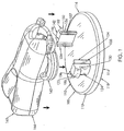
- a clip 100 for use in retaining a catheter hub 160 against a surface, such as the skin of a catheterized patient, is shown in perspective in Fig. 1 .
- the catheter hub 160 is the hub disclosed in U.S. Patent Publication No. US 2004/0097903 , as well as in U.S. Patent Publication No. US 2004/0092863.
- the clip 100 is constructed from a polymer such as polypropylene, or some other suitable material known to those skilled in the art.
- the material from which the clip 100 is constructed is preferably sufficiently flexible to allow portions of the clip 100 to flex when biased by an outside force, but to return generally toward or to an original position when the outside force is removed, as will be explained in more detail later herein.
- the clip 100 includes a generally planar base 110 having a first surface 112 and a second surface 114 juxtaposed from the first surface 112.
- the base 110 is preferably generally circular in shape, although those skilled in the art will recognize that the base 110 may be other shapes as well.
- the first surface 112 may have a beveled edge 116, as shown in Fig. 1 , although those skilled in the art will recognize that the edge 116 need not be beveled.
- the second surface 114 preferably includes a self-adhesive material 118, which is suitable for adhering a retaining device to the skin of a patient without sutures.
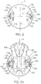
- a planar view of the clip 100 is shown in Fig. 2 and a planar view of the clip 100 with the hub 160 inserted thereon is shown in Fig. 2A .
- the base 110 is shown to be bisected by a first plane P1, which is perpendicular to the base 110, and a second plane P2 that is perpendicular to the plane P1.
- a first retaining section 120 is disposed on one side of the plane P1, while a second retaining section 140 is disposed across plane P1, preferably as a mirror image of the first retaining section 120 across the plane P1.
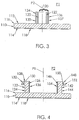
- a sectional view of the clip 100 taken along plane P1 is shown in Fig. 3
- a sectional view of the clip 100 taken along plane P2 is shown in Fig. 4 .
- the first retaining section 120 includes a first prong 122 that extends from the first surface 112, generally perpendicular to the first surface 112.
- the first prong 122 includes a generally arcuate outer face 124 with a convex curvature.
- the plane P2 bisects the first prong 122.
- An inner face 126, juxtaposed from the outer face 124, may be generally flat and parallel to the plane P1, although those skilled in the art will recognize that the inner face 126 need not be generally flat and need not be parallel to the plane P1.
- a free end portion 128 of the first prong 122 includes a first lip 130 that extends from the outer face 124 and away from the first plane P1, generally parallel to the base 110.
- a beveled face 132 extends from the farthest edge of the first lip 130 toward the first plane P1 and away from the base 110.
- the beveled face 132 is preferably arcuate, with a convex curvature, although those skilled in the art will recognize that the beveled face 132 need not be arcuate.
- a first locator pin 134 is disposed adjacent the first prong 122 on one side of the second plane P2 and a second locator pin 136 is disposed adjacent the first prong 122 on the opposing side of the second plane P2.
- the first and second locator pins 134, 136 are mirror images of each other across the second plane P2.
- an outside surface 135 of the first locator pin 134 is disposed distal from the first prong 122 and an outer surface 137 of the second pin 136 is disposed distal from the first prong 122.
- the second retaining section 140 is preferably a mirror image of the first retaining section 120 across both the first plane P1 and the second plane P2.
- the second retaining section 140 includes a second prong 142 that extends from the first surface 112, generally perpendicular to the first surface 112.
- the second prong 142 includes a generally arcuate outer face 144 with a convex curvature.
- the plane P2 bisects the second prong 142.
- An inner face 146, juxtaposed from the outer face 144, may be generally flat and parallel to the plane P1, although those skilled in the art will recognize that the inner face 146 need not be generally flat and need not be parallel to the plane P1.
- a free end portion 148 of the second prong 142 includes a second lip 150 that extends from the outer face 144 and away from the first plane P1, generally parallel to the base 110.
- a beveled face 152 extends from the farthest edge of the second lip 150 toward the first plane P1 and away from the base 110.
- the beveled face 152 is preferably arcuate, with a convex curvature, although those skilled in the art will recognize that the beveled face 152 need not be arcuate.
- a first locator pin 154 is disposed adjacent the second prong 142 on one side of the second plane P2 and a second locator pin 156 is disposed adjacent the second prong 142 on the opposing side of the second plane P2.
- the first and second locator pins 154, 156 are mirror images of each other across the second plane P2.
- an outside surface 155 of the first locator pin 154 is disposed distal from the second prong 142 and an outer surface 157 of the second pin 156 is disposed distal from the second prong 142.
- each suture loop or wing 162, 164 is generally semi-annular in shape, with an arcuate portion extending away from the body 166 of the hub 160.
- the first retaining section 120 is sized and spaced to fit in the first opening between the arcuate portion of the first suture loop or wing 162 and the body 166, while the second retaining section 140 is sized and spaced to fit in the second opening between the arcuate portion of the second suture loop or wing 164 and the body 166.
- the hub 160 is removably and longitudinally translatably secured to the catheter.
- the hub 160 is generally centered over the clip 100 so that a longitudinal plane of the hub 160 is generally co-planar with the first plane P1.
- the hub 160 and the clip 100 are then brought together so that the first suture loop or wing 162 engages the beveled face 132 of the first prong 122 and the second suture loop or wing 164 engages the beveled face 152 of the second prong 142.
- the force of each suture loop or wing 162,164 against each respective beveled face 132, 152 biases each of the first and second prongs 122, 142 toward the first plane P1.
- the preferably arcuate outer face 124 preferably biases against the inner arcuate wall of the first suture loop 162 or wing to firmly retain the first suture loop 162 or wing against the first prong 122.
- the first suture loop or wing 162 may bias each of the first and second locator pins 134, 136 toward the second plane P2, so that the first and second locator pins 134, 136 exert a reactive biasing force against the first suture loop or wing 162 to firmly engage the first suture loop or wing 162.
- the first and second locator pins 134, 136 restrict the hub 160 from longitudinally translating along an axis of the first plane P1, thus retaining the hub 160 securely against the clip 100.
- the biasing force against the second prong 142 is released, and the second prong 142 snaps back toward its original, pre-biased position, and the second suture loop or wing 164 is retained against the clip 100 by the second lip 150.
- the preferably arcuate outer face 144 preferably biases against the inner arcuate wall of the second suture loop or wing 164 to firmly retain the second suture loop or wing 164 against the second prong 142.
- the second suture loop or wing 164 may bias each of the first and second locator pins 154, 156 toward the second plane P2, so that the first and second locator pins 154, 156 exert a reactive biasing force against the second suture loop or wing 164 to firmly engage the second suture loop or wing 164.
- the first and second locator pins 154, 156 restrict the hub 160 from longitudinally translating along an axis of the first plane P1, thus retaining the hub 160 securely against the clip 100.
- the hub 160 is now securely connected to the clip 100, with restricted ability of the hub 160 to translate along axes of either plane P1 or P2.
- the hub 160 is then lifted away from the first surface 112 of the base 110, over the first and second prongs 120, 140, respectively, and away from the clip 100.
- the hub 160 may now be removed from the catheter. If desired, the clip 100 may be removed from the patient by peeling the second surface 114 of the clip 100 from the patient's skin. The hub 160 may be repositioned at a new location along the length of the catheter, if desired. The clip 100 may thusly be relocated to a different position on the patient's skin and the hub 160 may be reconnected to the clip 100 as described above; if the hub 160 is no longer to be used, the clip 100 may be discarded.
Description
- The present invention relates to an apparatus for releasably retaining a catheter hub to the skin of a patient.
- Catheters are commonly used to insert and remove fluids, such as medication and/or blood to and from the bloodstream of a patient. A catheter typically includes a connection point, such as a hub, that remains exterior of the patient after the catheter is inserted into the patient, and is used to secure the catheter to the patient to reduce the likelihood of the catheter being accidentally dislodged from the patient.
- After the catheter is installed, the catheter hub is typically fixedly connected to the patient's skin, such as by suturing the hub directly to the skin. To facilitate this suturing, the hub typically includes a pair of loops, or suture wings, that extend laterally from the hub through which sutures may be passed. The sutures secure the suture wings to the surface of the patient's skin, securing the hub to the patient and restricting the ability of the hub to move relative to the patient.
- However, such suturing produces skin penetration that may lead to infection in the patient. Others have developed adhesive-based structures for securing a catheter to the external skin of the patient. See, for example,
U.S. Patent Nos. 5,192,274 ;5,456,671 ;5,637,098 ;5,702,371 ;6,491,664 ; and6,572,588 , that all disclose various configurations of securing a catheter or catheter hub on a base structure, with a face of the base structure incorporating an adhesive to secure the catheter to the patient's skin without piercing the skin, such as with sutures. - Certain catheters, such as the Split Stream™ catheter manufactured and sold by Medical Components, Inc. of Harleysville, Pennsylvania, include a catheter ingrowth cuff that is subcutaneously implanted during catheter insertion. A removable hub is connected to the catheter and is intended to remain connected to the catheter only until subcutaneous skin tissue has had time to grow into the cuff to secure the cuff and the catheter subcutaneously. After the cuff is subcutaneously secured, it is preferred to remove the hub from the catheter, to alleviate any patient discomfort that may be caused by the hub rubbing against the skin.
-
US 2001/0039399 A1 refers to an anchoring system for a medical device. The anchoring system includes a simply-structured device which permits a portion of a catheter ton be easily anchored to a patient. The anchoring system comprises a retainer and an anchor pad. The retainer is sized and configured to accept and retain a section of the catheter within the anchoring system and includes a pair of posts and a clip. The posts are sized and configured to releasably accept holes formed in the catheter or catheter fitting. The clip is sized and configured to releasably accept a portion of the catheter. -
US 2001/0011164 A1 refers to a catheter anchoring system to securely anchor to a patient's skin a catheter and fluid supply tube interconnection. The anchoring system comprises a retainer configured to receive a catheter adaptor in a variety of positions. The adaptor interconnects the catheter and the fluid supply tube. The anchoring system additionally includes a flexible, adhesive anchor pad which supports a tube clip, as well as the retainer. The retainer includes a channel that is configured to receive an adaptor in a snap-fit manner comprising a plurality of lateral slots. Each slot is sized to receive and to capture an annular collar of catheter adaptor to prevent the adaptor from sliding within the channel. - It would be beneficial to provide a securing device that would releasably retain the hub for a catheter against the patient's skin without the need for suturing the hub to the skin.
- Briefly, the present disclosure provides a clip comprising a base having a first surface and a second surface juxtaposed from the first surface. The clip also includes a first section for retaining a catheter hub to the base, wherein the first section extends from the first surface and a second section for retaining the catheter hub to the base, wherein the second section extends from the first surface. The present invention relates to a clip as claimed hereafter. Preferred embodiments of the invention are set forth in the dependent claims.
- Additionally, the present invention also provides a method of releasably attaching a hub to a clip comprising providing a hub including a body disposed against the first surface of the base, a first loop disposed on a first side of the body, and a second loop disposed on a second side of the body. The method also includes providing a clip including a base having a first surface and a second surface juxtaposed from the first surface, a first section for retaining a catheter hub to the base, wherein the first section extends from the first surface, and a second section for retaining the catheter hub to the base, wherein the second section extends from the first surface. The method further includes disposing the first loop over the first section and disposing the second loop over the second section and urging the hub toward the first surface, thereby biasing at least a portion of the first section and at least a portion of the second section toward each other; and engaging the hub body against the first surface, thereby unbiasing at least the portion of the first section and at least the portion of the second section away from each other, retaining the first loop against the first section and retaining the second loop against the second section.
- The present invention further provides a method of removing a hub from a clip comprising providing a clip including a base having a first surface and a second surface juxtaposed from the first surface, a first section for retaining a catheter hub to the base, wherein the first section extends from the first surface; and a second section for retaining the catheter hub to the base, wherein the second section extends from the first surface. The method also includes providing a hub including a body disposed against the first surface of the base, a first loop disposed on a first side of the body, wherein the first loop is disposed over the first section for retaining the catheter hub to the base, and a second loop disposed on a second side of the body, wherein the second loop is disposed over the second section for retaining the catheter hub to the base. The method further includes disposing at least a portion of the first section and at least a portion of the second section toward each other; and disposing the hub away from the first surface of the base.
- The present invention also provides a clip for retaining a catheter hub against a surface. The clip comprises a base, a first plane bisecting the base; and a first hub clip extending from the base on a first side of the plane. The first hub clip comprises a first prong, a first locator pin disposed on a first side of the first prong and a second locator pin disposed on a second side of the first prong. The clip also comprises a second hub clip extending from the base on a second side of the plane. The second hub clip is a mirror image of the first hub clip across the plane.
- The accompanying drawings, which are incorporated herein and constitute part of this specification, illustrate the presently preferred embodiments of the invention, and, together with the general description given above and the detailed description given below, serve to explain the features of the invention. In the drawings:
-
Fig. 1 is a perspective view of acatheter clip 100 according to the present invention, with a catheter hub being inserted onto the clip. -
Fig. 2 is a top plan view of the catheter clip ofFig. 1 . -
Fig. 2A , is a top plan view of the catheter clip ofFig. 1 , with a catheter hub inserted onto the clip. -
Fig. 3 is a sectional view of the clip ofFig. 1 . -
Fig. 4 is a sectional view of the clip ofFig. 1 , taken along a line perpendicular to the section ofFig. 3 . - In the drawings, like numerals indicate like elements throughout. Certain terminology is used herein for convenience only and is not to be taken as a limitation on the present invention. The terminology includes words specifically mentioned, derivatives thereof, and words of similar import. The following describes a preferred embodiment of the invention. However, it should be understood based on this disclosure, that the invention is not limited by the preferred embodiment described herein.
- A
clip 100 for use in retaining acatheter hub 160 against a surface, such as the skin of a catheterized patient, is shown in perspective inFig. 1 . Preferably, thecatheter hub 160 is the hub disclosed in U.S. Patent Publication No.US 2004/0097903 , as well as in U.S. Patent Publication No. US 2004/0092863. - Preferably, the
clip 100 is constructed from a polymer such as polypropylene, or some other suitable material known to those skilled in the art. The material from which theclip 100 is constructed is preferably sufficiently flexible to allow portions of theclip 100 to flex when biased by an outside force, but to return generally toward or to an original position when the outside force is removed, as will be explained in more detail later herein. - The
clip 100 includes a generallyplanar base 110 having afirst surface 112 and asecond surface 114 juxtaposed from thefirst surface 112. Thebase 110 is preferably generally circular in shape, although those skilled in the art will recognize that the base 110 may be other shapes as well. Thefirst surface 112 may have abeveled edge 116, as shown inFig. 1 , although those skilled in the art will recognize that theedge 116 need not be beveled. Thesecond surface 114 preferably includes a self-adhesive material 118, which is suitable for adhering a retaining device to the skin of a patient without sutures. - A planar view of the
clip 100 is shown inFig. 2 and a planar view of theclip 100 with thehub 160 inserted thereon is shown inFig. 2A . Thebase 110 is shown to be bisected by a first plane P1, which is perpendicular to thebase 110, and a second plane P2 that is perpendicular to the plane P1. Afirst retaining section 120 is disposed on one side of the plane P1, while asecond retaining section 140 is disposed across plane P1, preferably as a mirror image of thefirst retaining section 120 across the plane P1. A sectional view of theclip 100 taken along plane P1 is shown inFig. 3 , while a sectional view of theclip 100 taken along plane P2 is shown inFig. 4 . - Referring to
Figs. 1-4 , thefirst retaining section 120 includes afirst prong 122 that extends from thefirst surface 112, generally perpendicular to thefirst surface 112. Thefirst prong 122 includes a generally arcuateouter face 124 with a convex curvature. As shown inFig. 3 , the plane P2 bisects thefirst prong 122. Aninner face 126, juxtaposed from theouter face 124, may be generally flat and parallel to the plane P1, although those skilled in the art will recognize that theinner face 126 need not be generally flat and need not be parallel to the plane P1. Afree end portion 128 of thefirst prong 122 includes afirst lip 130 that extends from theouter face 124 and away from the first plane P1, generally parallel to thebase 110. Abeveled face 132 extends from the farthest edge of thefirst lip 130 toward the first plane P1 and away from thebase 110. Thebeveled face 132 is preferably arcuate, with a convex curvature, although those skilled in the art will recognize that thebeveled face 132 need not be arcuate. - Referring now to
Fig. 3 , but still in reference to thefirst retaining section 120, afirst locator pin 134 is disposed adjacent thefirst prong 122 on one side of the second plane P2 and asecond locator pin 136 is disposed adjacent thefirst prong 122 on the opposing side of the second plane P2. Preferably, the first and second locator pins 134, 136 are mirror images of each other across the second plane P2. Also preferably, anoutside surface 135 of thefirst locator pin 134 is disposed distal from thefirst prong 122 and anouter surface 137 of thesecond pin 136 is disposed distal from thefirst prong 122. - The
second retaining section 140 is preferably a mirror image of thefirst retaining section 120 across both the first plane P1 and the second plane P2. Thesecond retaining section 140 includes asecond prong 142 that extends from thefirst surface 112, generally perpendicular to thefirst surface 112. Thesecond prong 142 includes a generally arcuateouter face 144 with a convex curvature. The plane P2 bisects thesecond prong 142. Aninner face 146, juxtaposed from theouter face 144, may be generally flat and parallel to the plane P1, although those skilled in the art will recognize that theinner face 146 need not be generally flat and need not be parallel to the plane P1. Afree end portion 148 of thesecond prong 142 includes asecond lip 150 that extends from theouter face 144 and away from the first plane P1, generally parallel to thebase 110. Abeveled face 152 extends from the farthest edge of thesecond lip 150 toward the first plane P1 and away from thebase 110. Thebeveled face 152 is preferably arcuate, with a convex curvature, although those skilled in the art will recognize that thebeveled face 152 need not be arcuate. - A
first locator pin 154 is disposed adjacent thesecond prong 142 on one side of the second plane P2 and asecond locator pin 156 is disposed adjacent thesecond prong 142 on the opposing side of the second plane P2. Preferably, the first and second locator pins 154, 156 are mirror images of each other across the second plane P2. Also preferably, anoutside surface 155 of thefirst locator pin 154 is disposed distal from thesecond prong 142 and anouter surface 157 of thesecond pin 156 is disposed distal from thesecond prong 142. - Referring back to
Fig. 2A , thehub 160 is inserted onto theclip 100 so that a suture loop orwing hub 160 engages the first andsecond retaining section sections hub 160 to theclip 100. As can be seen fromFig. 2A , each suture loop orwing body 166 of thehub 160. Thefirst retaining section 120 is sized and spaced to fit in the first opening between the arcuate portion of the first suture loop orwing 162 and thebody 166, while thesecond retaining section 140 is sized and spaced to fit in the second opening between the arcuate portion of the second suture loop orwing 164 and thebody 166. - In operation, after a catheter (not shown) is inserted into a patient, the
hub 160 is removably and longitudinally translatably secured to the catheter. Thehub 160 is generally centered over theclip 100 so that a longitudinal plane of thehub 160 is generally co-planar with the first plane P1. Thehub 160 and theclip 100 are then brought together so that the first suture loop orwing 162 engages thebeveled face 132 of thefirst prong 122 and the second suture loop orwing 164 engages thebeveled face 152 of thesecond prong 142. As thehub 160 is pressed against theclip 100, the force of each suture loop or wing 162,164 against each respectivebeveled face second prongs - After the first suture loop or
wing 162 has cleared thebeveled face 132 of thefirst prong 122, the biasing force against thefirst prong 122 is released, and thefirst prong 122 snaps back toward its original, pre-biased position, and the first suture loop orwing 162 is retained against theclip 100 by thefirst lip 130. The preferably arcuateouter face 124 preferably biases against the inner arcuate wall of thefirst suture loop 162 or wing to firmly retain thefirst suture loop 162 or wing against thefirst prong 122. - As the first suture loop or
wing 162 is being forced down over thefirst prong 122, the inner arcuate wall of the first suture loop orwing 162, proximate to thehub body 166, is being disposed around theoutside surfaces wing 162 may bias each of the first and second locator pins 134, 136 toward the second plane P2, so that the first and second locator pins 134, 136 exert a reactive biasing force against the first suture loop orwing 162 to firmly engage the first suture loop orwing 162. The first and second locator pins 134, 136 restrict thehub 160 from longitudinally translating along an axis of the first plane P1, thus retaining thehub 160 securely against theclip 100. - Likewise, after the second suture loop or
wing 164 has cleared thebeveled face 152 of thesecond prong 142, the biasing force against thesecond prong 142 is released, and thesecond prong 142 snaps back toward its original, pre-biased position, and the second suture loop orwing 164 is retained against theclip 100 by thesecond lip 150. The preferably arcuateouter face 144 preferably biases against the inner arcuate wall of the second suture loop orwing 164 to firmly retain the second suture loop orwing 164 against thesecond prong 142. - As the second suture loop or
wing 164 is being forced down over thesecond prong 142, the inner arcuate wall of the second suture loop orwing 164, proximate to thehub body 166, is being disposed around theoutside surfaces wing 164 may bias each of the first and second locator pins 154, 156 toward the second plane P2, so that the first and second locator pins 154, 156 exert a reactive biasing force against the second suture loop orwing 164 to firmly engage the second suture loop orwing 164. The first and second locator pins 154, 156 restrict thehub 160 from longitudinally translating along an axis of the first plane P1, thus retaining thehub 160 securely against theclip 100. - As shown in
Fig. 2A , thehub 160 is now securely connected to theclip 100, with restricted ability of thehub 160 to translate along axes of either plane P1 or P2. - In the event that it is desired to remove the
hub 160 from either the patient or the catheter, the beveled faces 132, 152 of each of the first andsecond prongs wings respective lip respective suture loop hub 160 is then lifted away from thefirst surface 112 of thebase 110, over the first andsecond prongs clip 100. - The
hub 160 may now be removed from the catheter. If desired, theclip 100 may be removed from the patient by peeling thesecond surface 114 of theclip 100 from the patient's skin. Thehub 160 may be repositioned at a new location along the length of the catheter, if desired. Theclip 100 may thusly be relocated to a different position on the patient's skin and thehub 160 may be reconnected to theclip 100 as described above; if thehub 160 is no longer to be used, theclip 100 may be discarded.
Claims (9)
- A clip (100) for retention of a catheter hub (160) to a surface, where the hub has a hub body (166) and a wing (162, 164) on either side of the hub body (166), the clip (100) comprising a base (110) having a first surface (112) and an second surface (114) juxtaposed from the first surface (112), and having first and second retaining sections (120; 140) including respective first and second prongs (122, 142) extending from the first surface (112), being engageable with the wings (162, 164) for releasably securing the catheter hub (160) to the clip (100),
the first and second prongs (122, 142) each having opposed outer and inner faces (124, 126; 144, 146) with a respective lip (130; 150) extending outward from each outer face (124; 144), and
each lip (130; 150) has a beveled face (132; 152) and characterized in that the first and second prongs (122; 142) are each configured to flex toward each other upon application of a force to the respective beveled face (132; 152) and to return to a respective original position when the force is removed. - The clip (100) according to claim 1, wherein the first and second prongs (122, 142) are adapted to be flexed toward each other for removal of the catheter hub (160) from the clip (100).
- The clip (100) according to claim 1, wherein the second surface (114) comprises an adhesive (118).
- The clip (100) according to claim 1, further comprising at least one locator pin (134, 136; 154, 156) adjacent to and separate from each of the first and second prongs (122, 142).
- The clip (100) according to claim 1, wherein a pair of locator pins (134, 136; 154, 156) are disposed adjacent to and separate from each of the first and second prongs (122, 142).
- A combination of a catheter hub (160) and a retaining clip (100), for securing a catheter assembly to a surface, comprising:the clip (100) according to claim 1, anda catheter hub (160) having a hub body (166) having opposite sides and including a bottom surface, and further having first and second loops (162, 164) extending from opposite sides defining respective first and second openings between the loops and the respective hub body sides,wherein free ends (128, 148) of the first and second prongs (122, 142) are sized to be received through the respective openings when inserting the catheter hub onto the clip, wherein the free ends include the respective lips (130, 150) that are sized to overlie the first and second loops when the catheter hub is urged against the clip base (110), and wherein the first and second prongs (122, 142) are biasable toward each other upon engagement by the first and second loops (162, 164) when the catheter hub (160) is urged toward the clip base and become unbiased when the bottom of the catheter hub is adjacent to the clip base (110).
- The combination according to claim 6, wherein a section of the hub body (160) comprising the loops (162, 164) is smaller than a distance between the first and second prong inner faces (126; 146).
- A method of releasably attaching a catheter hub (160) to a clip (100) comprising:providing a clip (100) and a catheter hub (160) of claim 6;disposing the first and second loops (162, 164) of the catheter hub over the first and second prongs (122, 142) respectively;urging the hub (160) toward the base (110), thereby biasing at least respective portions of the first and second prongs (122, 142) toward each other; andengaging the hub body (166) against the first surface (112) of the clip, thereby unbiasing the portions of the first and second prongs (122, 142), retaining the first and second loops against the first and second prongs (122, 142).
- A method of removing a catheter hub (160) from a clip (100) comprising:providing a clip (100) and a catheter hub (160) of claim 6, wherein the catheter hub (160) is disposed against the first surface (112) of the base (110) of the clip, with the lips (130; 150) of the first and second prongs (122; 142) disposed over the first and second loops (162, 164) of the hub (160), respectively;biasing the first and second prongs (122, 142) toward each other, whereafter the catheter hub is removable from the clip (100); anddisposing the hub (160) away from the first surface (112) of the base (110).
Applications Claiming Priority (2)
| Application Number | Priority Date | Filing Date | Title |
|---|---|---|---|
| US58798104P | 2004-07-14 | 2004-07-14 | |
| PCT/US2005/024648 WO2006019725A2 (en) | 2004-07-14 | 2005-07-12 | Catheter hub clip |
Publications (3)
| Publication Number | Publication Date |
|---|---|
| EP1773432A2 EP1773432A2 (en) | 2007-04-18 |
| EP1773432A4 EP1773432A4 (en) | 2010-02-17 |
| EP1773432B1 true EP1773432B1 (en) | 2016-03-16 |
Family
ID=35907858
Family Applications (1)
| Application Number | Title | Priority Date | Filing Date |
|---|---|---|---|
| EP05769306.1A Not-in-force EP1773432B1 (en) | 2004-07-14 | 2005-07-12 | Catheter hub clip |
Country Status (5)
| Country | Link |
|---|---|
| US (1) | US7220246B2 (en) |
| EP (1) | EP1773432B1 (en) |
| JP (1) | JP5070048B2 (en) |
| CA (1) | CA2573458C (en) |
| WO (1) | WO2006019725A2 (en) |
Families Citing this family (52)
| Publication number | Priority date | Publication date | Assignee | Title |
|---|---|---|---|---|
| US6702789B1 (en) | 1997-03-11 | 2004-03-09 | Alcove Medical, Inc. | Catheter having insertion control mechanism and anti-bunching mechanism |
| US20040054350A1 (en) * | 2002-09-17 | 2004-03-18 | Shaughnessy Michael C. | Enteral feeding unit having a reflux device and reflux method |
| US20040116899A1 (en) * | 2002-12-16 | 2004-06-17 | Shaughnessy Michael C. | Bolus for non-occluding high flow enteral feeding tube |
| US7393339B2 (en) | 2003-02-21 | 2008-07-01 | C. R. Bard, Inc. | Multi-lumen catheter with separate distal tips |
| US20040243095A1 (en) | 2003-05-27 | 2004-12-02 | Shekhar Nimkar | Methods and apparatus for inserting multi-lumen spit-tip catheters into a blood vessel |
| US8182485B1 (en) * | 2003-11-21 | 2012-05-22 | Toby Orthopaedics, Llc | Fracture fixation system |
| US7572274B2 (en) * | 2004-05-27 | 2009-08-11 | Cardiva Medical, Inc. | Self-tensioning vascular occlusion device and method for its use |
| US7993366B2 (en) | 2004-05-27 | 2011-08-09 | Cardiva Medical, Inc. | Self-tensioning vascular occlusion device and method for its use |
| US20080154303A1 (en) | 2006-12-21 | 2008-06-26 | Cardiva Medical, Inc. | Hemostasis-enhancing device and method for its use |
| US8992454B2 (en) * | 2004-06-09 | 2015-03-31 | Bard Access Systems, Inc. | Splitable tip catheter with bioresorbable adhesive |
| US7976518B2 (en) * | 2005-01-13 | 2011-07-12 | Corpak Medsystems, Inc. | Tubing assembly and signal generator placement control device and method for use with catheter guidance systems |
| US20070060898A1 (en) * | 2005-09-07 | 2007-03-15 | Shaughnessy Michael C | Enteral medical treatment assembly having a safeguard against erroneous connection with an intravascular treatment system |
| DE602007004718D1 (en) | 2006-03-31 | 2010-03-25 | Bard Inc C R | Catheter with arched transition area |
| US7856745B2 (en) * | 2006-08-24 | 2010-12-28 | Medical Components Inc. | Information clip for flexible tubing |
| CN101918065A (en) * | 2007-10-17 | 2010-12-15 | 巴德阿克塞斯系统股份有限公司 | Conduit with arterial lumens of expansion |
| CN101918066B (en) * | 2007-10-17 | 2013-07-31 | 巴德阿克塞斯系统股份有限公司 | Manufacture of split tip catheters and the split tip catheters |
| US8292841B2 (en) | 2007-10-26 | 2012-10-23 | C. R. Bard, Inc. | Solid-body catheter including lateral distal openings |
| US8066660B2 (en) | 2007-10-26 | 2011-11-29 | C. R. Bard, Inc. | Split-tip catheter including lateral distal openings |
| US9579485B2 (en) | 2007-11-01 | 2017-02-28 | C. R. Bard, Inc. | Catheter assembly including a multi-lumen configuration |
| JP5452498B2 (en) | 2007-11-01 | 2014-03-26 | シー・アール・バード・インコーポレーテッド | Catheter assembly including triple lumen end |
| WO2009102346A1 (en) * | 2008-02-15 | 2009-08-20 | Spire Corporation | Fusion manufacture of multi-lumen catheters |
| US20090205189A1 (en) * | 2008-02-15 | 2009-08-20 | Spire Corporation | Manufacture of fixed tip catheters |
| AU2009223517B2 (en) | 2008-03-10 | 2015-02-12 | Eduardo Gonzalez-Hernandez | Bone fixation system |
| US20090264936A1 (en) | 2008-04-17 | 2009-10-22 | Eduardo Gonzalez-Hernandez | Soft tissue attachment system and clip |
| US8419689B2 (en) * | 2008-09-30 | 2013-04-16 | Covidien Lp | Enclosing package for medical port and cover |
| US8795237B2 (en) * | 2008-09-30 | 2014-08-05 | Covidien Lp | Transparent catheter securement system |
| CN102740786A (en) * | 2009-12-22 | 2012-10-17 | 托比骨科有限公司 | Bone plate and tool assembly and method for use thereof |
| US8961573B2 (en) | 2010-10-05 | 2015-02-24 | Toby Orthopaedics, Inc. | System and method for facilitating repair and reattachment of comminuted bone portions |
| WO2012058448A2 (en) | 2010-10-27 | 2012-05-03 | Toby Orthopaedics, Llc | System and method for fracture replacement of comminuted bone fractures or portions thereof adjacent bone joints |
| WO2012119146A2 (en) | 2011-03-03 | 2012-09-07 | Toby Orthopaedics, Llc | Anterior lesser tuberosity fixed angle fixation device and method of use associated therewith |
| US9028441B2 (en) | 2011-09-08 | 2015-05-12 | Corpak Medsystems, Inc. | Apparatus and method used with guidance system for feeding and suctioning |
| JP5818614B2 (en) | 2011-09-28 | 2015-11-18 | 日本コヴィディエン株式会社 | Catheter fixture |
| JP5818613B2 (en) | 2011-09-28 | 2015-11-18 | 日本コヴィディエン株式会社 | Catheter fixture |
| US9730797B2 (en) | 2011-10-27 | 2017-08-15 | Toby Orthopaedics, Inc. | Bone joint replacement and repair assembly and method of repairing and replacing a bone joint |
| US9271772B2 (en) | 2011-10-27 | 2016-03-01 | Toby Orthopaedics, Inc. | System and method for fracture replacement of comminuted bone fractures or portions thereof adjacent bone joints |
| US9402667B2 (en) | 2011-11-09 | 2016-08-02 | Eduardo Gonzalez-Hernandez | Apparatus and method for use of the apparatus for fracture fixation of the distal humerus |
| WO2013157077A1 (en) * | 2012-04-17 | 2013-10-24 | Dehara Makoto | Linear object operation assist tool |
| JP2015526255A (en) * | 2012-08-31 | 2015-09-10 | スリーエム イノベイティブ プロパティズ カンパニー | Medical article fixing system and method of use thereof |
| US9283008B2 (en) | 2012-12-17 | 2016-03-15 | Toby Orthopaedics, Inc. | Bone plate for plate osteosynthesis and method for use thereof |
| US10252023B2 (en) | 2013-01-11 | 2019-04-09 | C. R. Bard, Inc. | Curved catheter and methods for making same |
| USD748252S1 (en) | 2013-02-08 | 2016-01-26 | C. R. Bard, Inc. | Multi-lumen catheter tip |
| US9333014B2 (en) | 2013-03-15 | 2016-05-10 | Eduardo Gonzalez-Hernandez | Bone fixation and reduction apparatus and method for fixation and reduction of a distal bone fracture and malunion |
| WO2015123684A1 (en) * | 2014-02-17 | 2015-08-20 | The Johns Hopkins University | Securement device with attachable members for use with a catheter |
| WO2016011091A1 (en) | 2014-07-14 | 2016-01-21 | C. R. Bard, Inc. | Apparatuses, systems, and methods for inserting split tip catheters having enhanced stiffening and guiding features |
| US10034971B2 (en) * | 2014-09-22 | 2018-07-31 | Indiana University Research And Technology Corporation | Tube securing device |
| US10946174B2 (en) | 2014-09-22 | 2021-03-16 | Indiana University Research And Technology Corporation | Tube securing device |
| MX2015001485A (en) * | 2015-01-30 | 2016-07-29 | Equipos Médicos Vizcarra S A | Central venous catheter with adherent canopy and elastic pipelines. |
| WO2018125845A1 (en) | 2016-12-27 | 2018-07-05 | Vasonics, Llc | Catheter housing |
| US10799312B2 (en) | 2017-04-28 | 2020-10-13 | Edwards Lifesciences Corporation | Medical device stabilizing apparatus and method of use |
| CN109276796B (en) * | 2018-09-17 | 2022-06-03 | 西安交通大学医学院第一附属医院 | Drainage tube with scale and fixing device |
| US11931525B2 (en) | 2018-10-04 | 2024-03-19 | Edwards Lifesciences Corporation | Stabilizer for a delivery system |
| JP7134583B1 (en) | 2021-07-30 | 2022-09-12 | 尚 堀田 | Plant molding method |
Family Cites Families (32)
| Publication number | Priority date | Publication date | Assignee | Title |
|---|---|---|---|---|
| US4397647A (en) * | 1979-01-19 | 1983-08-09 | Whitman Medical Corporation | Catheter stabilization fitting having a snap-over cover |
| US4645492A (en) * | 1983-10-11 | 1987-02-24 | Medical Engineering Corporation | Catheter anchoring device |
| FR2556586B1 (en) * | 1983-12-20 | 1988-10-14 | Biotrol Sa Lab | DEVICE FOR THE FLOW OF URINE FROM UROSTOMIES |
| US4711636A (en) * | 1985-11-08 | 1987-12-08 | Bierman Steven F | Catheterization system |
| US4699616A (en) * | 1986-06-13 | 1987-10-13 | Hollister Incorporated | Catheter retention device and method |
| DE8802756U1 (en) * | 1988-03-02 | 1988-04-14 | B. Braun Melsungen Ag, 3508 Melsungen, De | |
| US5578013A (en) * | 1989-07-24 | 1996-11-26 | Venetec International, Inc. | Catheter anchoring system |
| US5354282A (en) * | 1990-05-04 | 1994-10-11 | Bierman Steven F | Catheter anchoring system |
| US5456671A (en) * | 1989-07-24 | 1995-10-10 | Bierman; Steven F. | Catheter anchoring system |
| US5314411A (en) * | 1989-07-24 | 1994-05-24 | Steven F. Bierman, M.D. | Catheterization system with universal retention device and method of use |
| US5192273A (en) * | 1989-07-24 | 1993-03-09 | Steven F. Bierman | Catheterization system |
| US5702371A (en) * | 1989-07-24 | 1997-12-30 | Venetec International, Inc. | Tube fitting anchoring system |
| US6290676B1 (en) * | 1989-07-24 | 2001-09-18 | Venetec International, Inc. | Catheter anchoring system |
| US5224935A (en) * | 1990-05-02 | 1993-07-06 | E. R. Squibb & Sons, Inc. | Catheter retainer |
| US5192274A (en) * | 1991-05-08 | 1993-03-09 | Bierman Steven F | Anchor pad for catheterization system |
| US6786892B2 (en) | 1993-03-19 | 2004-09-07 | Venetec International, Inc. | Catheter anchoring system |
| US5800402A (en) * | 1993-03-19 | 1998-09-01 | Venetec International, Inc. | Catheter anchoring system and method of use |
| USD347060S (en) * | 1993-07-14 | 1994-05-17 | Bierman Steven F | Catheter adapter retainer |
| USD375355S (en) * | 1995-03-14 | 1996-11-05 | Venetec International, Inc. | Anchor pad with release layer |
| JPH08299448A (en) * | 1995-05-11 | 1996-11-19 | Terumo Corp | Indwelling catheter |
| US5637098A (en) * | 1995-08-07 | 1997-06-10 | Venetec International, Inc. | Catheter securement device |
| US5810781A (en) * | 1995-10-24 | 1998-09-22 | Venetec International, Inc. | Catheter fitting securement device |
| US5795335A (en) * | 1997-02-26 | 1998-08-18 | Zinreich; Eva S. | Intravenous tube restraint and cover device |
| US6213979B1 (en) * | 1997-05-29 | 2001-04-10 | Venetec International, Inc. | Medical line anchoring system |
| US6132398A (en) * | 1997-10-17 | 2000-10-17 | Venetec International, Inc. | Medical tubing securement system |
| US6224571B1 (en) * | 1997-11-14 | 2001-05-01 | Venetec International, Inc. | Medical line securement device |
| US6491664B2 (en) * | 1998-08-18 | 2002-12-10 | Venetec International, Inc. | Anchoring system for a medical article |
| US6572588B1 (en) * | 2000-03-10 | 2003-06-03 | Venetec International, Inc. | Medical anchoring system |
| US6428515B1 (en) * | 2000-06-01 | 2002-08-06 | Venetec International, Inc. | Anchoring system for leur lock connector |
| US7491190B2 (en) * | 2000-06-01 | 2009-02-17 | Venetec International, Inc. | Anchoring system for luer lock connector |
| US7261708B2 (en) * | 2002-10-31 | 2007-08-28 | Medical Components, Inc. | Removable catheter hub |
| US7413561B2 (en) * | 2003-08-13 | 2008-08-19 | Medical Components, Inc. | Conduit retaining clip |
-
2005
- 2005-07-12 EP EP05769306.1A patent/EP1773432B1/en not_active Not-in-force
- 2005-07-12 WO PCT/US2005/024648 patent/WO2006019725A2/en not_active Application Discontinuation
- 2005-07-12 US US11/179,421 patent/US7220246B2/en active Active
- 2005-07-12 JP JP2007521558A patent/JP5070048B2/en not_active Expired - Fee Related
- 2005-07-12 CA CA2573458A patent/CA2573458C/en not_active Expired - Fee Related
Also Published As
| Publication number | Publication date |
|---|---|
| US7220246B2 (en) | 2007-05-22 |
| WO2006019725A2 (en) | 2006-02-23 |
| CA2573458A1 (en) | 2006-02-23 |
| JP2008506460A (en) | 2008-03-06 |
| CA2573458C (en) | 2011-12-06 |
| EP1773432A4 (en) | 2010-02-17 |
| WO2006019725A3 (en) | 2007-05-03 |
| US20060015072A1 (en) | 2006-01-19 |
| JP5070048B2 (en) | 2012-11-07 |
| EP1773432A2 (en) | 2007-04-18 |
Similar Documents
| Publication | Publication Date | Title |
|---|---|---|
| EP1773432B1 (en) | Catheter hub clip | |
| US5722959A (en) | Catheter securement device | |
| US10874835B2 (en) | Systems and methods for anchoring medical devices | |
| US6447485B2 (en) | Medical line anchoring system | |
| EP0843567B1 (en) | Catheter anchoring system | |
| US6290676B1 (en) | Catheter anchoring system | |
| US20010011164A1 (en) | Catheter anchoring system | |
| JP2003534106A (en) | Fixing system for luer lock connector | |
| WO1997015342A9 (en) | Catheter fitting securement device | |
| AU777173B2 (en) | Medical line anchoring system |
Legal Events
| Date | Code | Title | Description |
|---|---|---|---|
| PUAI | Public reference made under article 153(3) epc to a published international application that has entered the european phase |
Free format text: ORIGINAL CODE: 0009012 |
|
| 17P | Request for examination filed |
Effective date: 20070109 |
|
| AK | Designated contracting states |
Kind code of ref document: A2 Designated state(s): AT BE BG CH CY CZ DE DK EE ES FI FR GB GR HU IE IS IT LI LT LU LV MC NL PL PT RO SE SI SK TR |
|
| AX | Request for extension of the european patent |
Extension state: AL BA HR MK YU |
|
| R17D | Deferred search report published (corrected) |
Effective date: 20070503 |
|
| DAX | Request for extension of the european patent (deleted) | ||
| A4 | Supplementary search report drawn up and despatched |
Effective date: 20100115 |
|
| RIC1 | Information provided on ipc code assigned before grant |
Ipc: A61M 25/02 20060101ALI20100111BHEP Ipc: A61M 5/32 20060101AFI20060725BHEP |
|
| 17Q | First examination report despatched |
Effective date: 20130206 |
|
| GRAP | Despatch of communication of intention to grant a patent |
Free format text: ORIGINAL CODE: EPIDOSNIGR1 |
|
| INTG | Intention to grant announced |
Effective date: 20151001 |
|
| GRAS | Grant fee paid |
Free format text: ORIGINAL CODE: EPIDOSNIGR3 |
|
| GRAA | (expected) grant |
Free format text: ORIGINAL CODE: 0009210 |
|
| AK | Designated contracting states |
Kind code of ref document: B1 Designated state(s): AT BE BG CH CY CZ DE DK EE ES FI FR GB GR HU IE IS IT LI LT LU LV MC NL PL PT RO SE SI SK TR |
|
| REG | Reference to a national code |
Ref country code: GB Ref legal event code: FG4D |
|
| REG | Reference to a national code |
Ref country code: CH Ref legal event code: EP |
|
| REG | Reference to a national code |
Ref country code: IE Ref legal event code: FG4D |
|
| REG | Reference to a national code |
Ref country code: AT Ref legal event code: REF Ref document number: 780649 Country of ref document: AT Kind code of ref document: T Effective date: 20160415 |
|
| REG | Reference to a national code |
Ref country code: DE Ref legal event code: R096 Ref document number: 602005048676 Country of ref document: DE |
|
| REG | Reference to a national code |
Ref country code: NL Ref legal event code: MP Effective date: 20160316 |
|
| REG | Reference to a national code |
Ref country code: LT Ref legal event code: MG4D |
|
| PG25 | Lapsed in a contracting state [announced via postgrant information from national office to epo] |
Ref country code: GR Free format text: LAPSE BECAUSE OF FAILURE TO SUBMIT A TRANSLATION OF THE DESCRIPTION OR TO PAY THE FEE WITHIN THE PRESCRIBED TIME-LIMIT Effective date: 20160617 Ref country code: FI Free format text: LAPSE BECAUSE OF FAILURE TO SUBMIT A TRANSLATION OF THE DESCRIPTION OR TO PAY THE FEE WITHIN THE PRESCRIBED TIME-LIMIT Effective date: 20160316 |
|
| REG | Reference to a national code |
Ref country code: AT Ref legal event code: MK05 Ref document number: 780649 Country of ref document: AT Kind code of ref document: T Effective date: 20160316 |
|
| PG25 | Lapsed in a contracting state [announced via postgrant information from national office to epo] |
Ref country code: NL Free format text: LAPSE BECAUSE OF FAILURE TO SUBMIT A TRANSLATION OF THE DESCRIPTION OR TO PAY THE FEE WITHIN THE PRESCRIBED TIME-LIMIT Effective date: 20160316 Ref country code: LT Free format text: LAPSE BECAUSE OF FAILURE TO SUBMIT A TRANSLATION OF THE DESCRIPTION OR TO PAY THE FEE WITHIN THE PRESCRIBED TIME-LIMIT Effective date: 20160316 Ref country code: SE Free format text: LAPSE BECAUSE OF FAILURE TO SUBMIT A TRANSLATION OF THE DESCRIPTION OR TO PAY THE FEE WITHIN THE PRESCRIBED TIME-LIMIT Effective date: 20160316 Ref country code: LV Free format text: LAPSE BECAUSE OF FAILURE TO SUBMIT A TRANSLATION OF THE DESCRIPTION OR TO PAY THE FEE WITHIN THE PRESCRIBED TIME-LIMIT Effective date: 20160316 |
|
| PG25 | Lapsed in a contracting state [announced via postgrant information from national office to epo] |
Ref country code: IS Free format text: LAPSE BECAUSE OF FAILURE TO SUBMIT A TRANSLATION OF THE DESCRIPTION OR TO PAY THE FEE WITHIN THE PRESCRIBED TIME-LIMIT Effective date: 20160716 Ref country code: EE Free format text: LAPSE BECAUSE OF FAILURE TO SUBMIT A TRANSLATION OF THE DESCRIPTION OR TO PAY THE FEE WITHIN THE PRESCRIBED TIME-LIMIT Effective date: 20160316 Ref country code: PL Free format text: LAPSE BECAUSE OF FAILURE TO SUBMIT A TRANSLATION OF THE DESCRIPTION OR TO PAY THE FEE WITHIN THE PRESCRIBED TIME-LIMIT Effective date: 20160316 |
|
| PG25 | Lapsed in a contracting state [announced via postgrant information from national office to epo] |
Ref country code: ES Free format text: LAPSE BECAUSE OF FAILURE TO SUBMIT A TRANSLATION OF THE DESCRIPTION OR TO PAY THE FEE WITHIN THE PRESCRIBED TIME-LIMIT Effective date: 20160316 Ref country code: SK Free format text: LAPSE BECAUSE OF FAILURE TO SUBMIT A TRANSLATION OF THE DESCRIPTION OR TO PAY THE FEE WITHIN THE PRESCRIBED TIME-LIMIT Effective date: 20160316 Ref country code: PT Free format text: LAPSE BECAUSE OF FAILURE TO SUBMIT A TRANSLATION OF THE DESCRIPTION OR TO PAY THE FEE WITHIN THE PRESCRIBED TIME-LIMIT Effective date: 20160718 Ref country code: AT Free format text: LAPSE BECAUSE OF FAILURE TO SUBMIT A TRANSLATION OF THE DESCRIPTION OR TO PAY THE FEE WITHIN THE PRESCRIBED TIME-LIMIT Effective date: 20160316 Ref country code: CZ Free format text: LAPSE BECAUSE OF FAILURE TO SUBMIT A TRANSLATION OF THE DESCRIPTION OR TO PAY THE FEE WITHIN THE PRESCRIBED TIME-LIMIT Effective date: 20160316 Ref country code: RO Free format text: LAPSE BECAUSE OF FAILURE TO SUBMIT A TRANSLATION OF THE DESCRIPTION OR TO PAY THE FEE WITHIN THE PRESCRIBED TIME-LIMIT Effective date: 20160316 |
|
| REG | Reference to a national code |
Ref country code: DE Ref legal event code: R097 Ref document number: 602005048676 Country of ref document: DE |
|
| PG25 | Lapsed in a contracting state [announced via postgrant information from national office to epo] |
Ref country code: BE Free format text: LAPSE BECAUSE OF FAILURE TO SUBMIT A TRANSLATION OF THE DESCRIPTION OR TO PAY THE FEE WITHIN THE PRESCRIBED TIME-LIMIT Effective date: 20160316 Ref country code: IT Free format text: LAPSE BECAUSE OF FAILURE TO SUBMIT A TRANSLATION OF THE DESCRIPTION OR TO PAY THE FEE WITHIN THE PRESCRIBED TIME-LIMIT Effective date: 20160316 |
|
| PLBE | No opposition filed within time limit |
Free format text: ORIGINAL CODE: 0009261 |
|
| STAA | Information on the status of an ep patent application or granted ep patent |
Free format text: STATUS: NO OPPOSITION FILED WITHIN TIME LIMIT |
|
| PG25 | Lapsed in a contracting state [announced via postgrant information from national office to epo] |
Ref country code: DK Free format text: LAPSE BECAUSE OF FAILURE TO SUBMIT A TRANSLATION OF THE DESCRIPTION OR TO PAY THE FEE WITHIN THE PRESCRIBED TIME-LIMIT Effective date: 20160316 |
|
| REG | Reference to a national code |
Ref country code: DE Ref legal event code: R119 Ref document number: 602005048676 Country of ref document: DE |
|
| 26N | No opposition filed |
Effective date: 20161219 |
|
| PG25 | Lapsed in a contracting state [announced via postgrant information from national office to epo] |
Ref country code: BG Free format text: LAPSE BECAUSE OF FAILURE TO SUBMIT A TRANSLATION OF THE DESCRIPTION OR TO PAY THE FEE WITHIN THE PRESCRIBED TIME-LIMIT Effective date: 20160616 |
|
| REG | Reference to a national code |
Ref country code: CH Ref legal event code: PL |
|
| GBPC | Gb: european patent ceased through non-payment of renewal fee |
Effective date: 20160712 |
|
| PG25 | Lapsed in a contracting state [announced via postgrant information from national office to epo] |
Ref country code: MC Free format text: LAPSE BECAUSE OF FAILURE TO SUBMIT A TRANSLATION OF THE DESCRIPTION OR TO PAY THE FEE WITHIN THE PRESCRIBED TIME-LIMIT Effective date: 20160316 |
|
| PG25 | Lapsed in a contracting state [announced via postgrant information from national office to epo] |
Ref country code: FR Free format text: LAPSE BECAUSE OF NON-PAYMENT OF DUE FEES Effective date: 20160801 Ref country code: DE Free format text: LAPSE BECAUSE OF NON-PAYMENT OF DUE FEES Effective date: 20170201 Ref country code: LI Free format text: LAPSE BECAUSE OF NON-PAYMENT OF DUE FEES Effective date: 20160731 Ref country code: CH Free format text: LAPSE BECAUSE OF NON-PAYMENT OF DUE FEES Effective date: 20160731 |
|
| REG | Reference to a national code |
Ref country code: FR Ref legal event code: ST Effective date: 20170331 |
|
| REG | Reference to a national code |
Ref country code: IE Ref legal event code: MM4A |
|
| PG25 | Lapsed in a contracting state [announced via postgrant information from national office to epo] |
Ref country code: GB Free format text: LAPSE BECAUSE OF NON-PAYMENT OF DUE FEES Effective date: 20160712 Ref country code: SI Free format text: LAPSE BECAUSE OF FAILURE TO SUBMIT A TRANSLATION OF THE DESCRIPTION OR TO PAY THE FEE WITHIN THE PRESCRIBED TIME-LIMIT Effective date: 20160316 |
|
| PG25 | Lapsed in a contracting state [announced via postgrant information from national office to epo] |
Ref country code: IE Free format text: LAPSE BECAUSE OF NON-PAYMENT OF DUE FEES Effective date: 20160712 |
|
| PG25 | Lapsed in a contracting state [announced via postgrant information from national office to epo] |
Ref country code: LU Free format text: LAPSE BECAUSE OF NON-PAYMENT OF DUE FEES Effective date: 20160712 |
|
| PG25 | Lapsed in a contracting state [announced via postgrant information from national office to epo] |
Ref country code: HU Free format text: LAPSE BECAUSE OF FAILURE TO SUBMIT A TRANSLATION OF THE DESCRIPTION OR TO PAY THE FEE WITHIN THE PRESCRIBED TIME-LIMIT; INVALID AB INITIO Effective date: 20050712 Ref country code: CY Free format text: LAPSE BECAUSE OF FAILURE TO SUBMIT A TRANSLATION OF THE DESCRIPTION OR TO PAY THE FEE WITHIN THE PRESCRIBED TIME-LIMIT Effective date: 20160316 |
|
| PG25 | Lapsed in a contracting state [announced via postgrant information from national office to epo] |
Ref country code: TR Free format text: LAPSE BECAUSE OF FAILURE TO SUBMIT A TRANSLATION OF THE DESCRIPTION OR TO PAY THE FEE WITHIN THE PRESCRIBED TIME-LIMIT Effective date: 20160316 |