EP1773031B1 - Portable communication apparatus with display positionable at an angle - Google Patents
Portable communication apparatus with display positionable at an angle Download PDFInfo
- Publication number
- EP1773031B1 EP1773031B1 EP06021026A EP06021026A EP1773031B1 EP 1773031 B1 EP1773031 B1 EP 1773031B1 EP 06021026 A EP06021026 A EP 06021026A EP 06021026 A EP06021026 A EP 06021026A EP 1773031 B1 EP1773031 B1 EP 1773031B1
- Authority
- EP
- European Patent Office
- Prior art keywords
- housing
- communication apparatus
- portable communication
- pair
- rotation axis
- Prior art date
- Legal status (The legal status is an assumption and is not a legal conclusion. Google has not performed a legal analysis and makes no representation as to the accuracy of the status listed.)
- Expired - Fee Related
Links
Images


Classifications
-
- H—ELECTRICITY
- H04—ELECTRIC COMMUNICATION TECHNIQUE
- H04B—TRANSMISSION
- H04B1/00—Details of transmission systems, not covered by a single one of groups H04B3/00 - H04B13/00; Details of transmission systems not characterised by the medium used for transmission
- H04B1/38—Transceivers, i.e. devices in which transmitter and receiver form a structural unit and in which at least one part is used for functions of transmitting and receiving
- H04B1/40—Circuits
-
- H—ELECTRICITY
- H04—ELECTRIC COMMUNICATION TECHNIQUE
- H04M—TELEPHONIC COMMUNICATION
- H04M1/00—Substation equipment, e.g. for use by subscribers
- H04M1/02—Constructional features of telephone sets
- H04M1/0202—Portable telephone sets, e.g. cordless phones, mobile phones or bar type handsets
- H04M1/0206—Portable telephones comprising a plurality of mechanically joined movable body parts, e.g. hinged housings
- H04M1/0208—Portable telephones comprising a plurality of mechanically joined movable body parts, e.g. hinged housings characterized by the relative motions of the body parts
- H04M1/0235—Slidable or telescopic telephones, i.e. with a relative translation movement of the body parts; Telephones using a combination of translation and other relative motions of the body parts
-
- H—ELECTRICITY
- H04—ELECTRIC COMMUNICATION TECHNIQUE
- H04M—TELEPHONIC COMMUNICATION
- H04M1/00—Substation equipment, e.g. for use by subscribers
- H04M1/02—Constructional features of telephone sets
- H04M1/0202—Portable telephone sets, e.g. cordless phones, mobile phones or bar type handsets
- H04M1/0206—Portable telephones comprising a plurality of mechanically joined movable body parts, e.g. hinged housings
- H04M1/0208—Portable telephones comprising a plurality of mechanically joined movable body parts, e.g. hinged housings characterized by the relative motions of the body parts
- H04M1/0214—Foldable telephones, i.e. with body parts pivoting to an open position around an axis parallel to the plane they define in closed position
Definitions
- the present invention generally relates to a portable communication apparatus. More particularly, the present invention relates to a portable communication apparatus with a Liquid Crystal Device (LCD) that can slide and stand at a desired angle.
- LCD Liquid Crystal Device
- a "portable apparatus” is an apparatus which a user can carry with him/her to perform wireless communication with a partner.
- portable apparatuses include HHPs (hand held phones), CT-2 cellular phones, digital phones, PCS (personal communication service) phones, and PDAs (personal digital assistants).
- Conventional wireless terminals may be classified into various types according to their appearance.
- wireless terminals may be classified into bar-type wireless terminals, flip-type wireless terminals, and folder-type wireless terminals according to their appearance.
- a bar-type wireless terminal has a single housing shaped like a bar.
- a flip-type wireless terminal has a flip which is pivotally mounted to a bar-shaped housing by a hinge unit.
- a folder-type wireless terminal has a folder coupled to a single bar-shaped housing by a hinge unit in such a manner that the folder can be rotated to be folded to or unfolded from the housing.
- a camera phone equipped with a camera lens module which enables a user to perform image communication with a partner or take a picture of a desired subject.
- portable terminals With the rapid spread of portable terminals, the use of portable terminals has become commonplace. This has led to a tendency toward developing complex portable terminals that have not only simple calling functions, but also various functions to meet users' demands. For example, various additional services like on-demand video viewing, image communication, digital camera functions, Internet services, and TV viewing (as well as voice communication) are provided through the portable terminals.
- DMB Digital Multimedia Broadcasting
- the support device for the conventional portable terminal must basically include at least three leg portions and fixing portions, the volume and weight of the support device are large. Also, the support device must be carried even after the device is no longer being used.
- US 2006/0073859 discloses a handheld electronic device with a display screen, a body and a sliding mechanism by which the display screen can e tilted to an angle for the user to view.
- the sliding mechanism allows only a limited adjustment of the viewing angle.
- an aspect of the present invention is to provide a portable communication apparatus in which an LCD can slide and stand at a desired angle, thereby allowing a user to easily watch TV and moving pictures.
- a portable communication apparatus including the features of claim 1.
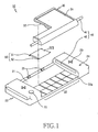
- a portable communication apparatus 10 includes a first housing 20, a second housing 30, a guide means 40, and a rotational moving means 50.
- the first housing 20 extends in a longitudinal direction to face the second housing 30 and the second housing 30 is positioned on the first housing 20 such that it slides substantially perpendicularly to the longitudinal direction and rotates to stand at a desired angle.
- the guide means 40 is included in both ends of the first housing 20 to guide the sliding movement of the second housing 30.
- the rotational moving means 50 is included between the first housing 20 and the second housing 30 to rotate in such a way to make the second housing 30 stand at a desired angle.
- a mounting face 21 recessed to a predetermined depth is formed on the first housing 20 to allow the second housing to be mounted thereon and allow the second housing 30 to slide and rotate with respect to the first housing 20.
- the mounting face 21 has a curved surface to facilitate sliding and rotation of the second housing 30.
- the first housing 20 includes a keypad 22 including a plurality of keys 22a.
- the keypad 22 is opened or closed by sliding the second housing 30.
- the second housing 30 includes a Liquid Crystal Display (LCD) 31 to facilitate watching TV and moving pictures.
- LCD Liquid Crystal Display
- the guide means 40 includes a pair of guide members 41 and guide holes 42.
- the guide members 41 are formed at both ends of the second housing 30 to be slidably combined with the guide holes 42.
- the guide holes 42 are substantially perpendicular to the longitudinal direction of the first housing 20 so that the guide members 41 may slide within the guide holes 42 and rotate with respect to a rotation axis A1.
- the first housing 20 includes speaker devices 23 and a microphone device 24.
- the rotational moving means 50 includes a link member 53 to allow the second housing 30 to be folded or rotated so that the second housing 30 is angled with respect to a first link rotation axis L1 and a second link rotation axis L2 during sliding of the second housing 30.
- a first end 51 of the link member 53 provides the first link rotation axis L1 and can be rotatably combined with a pair of link arms 25 formed in the first housing 20.
- a second end 52 of the link member 53 provides the second link rotation axis L2 and can be rotatably combined with the back side of the second housing 30.
- a resting groove 32 is formed in the back side of the second housing 30 to rest the link member 53 thereon according to the sliding and rotation of the second housing 30.
- the portable communication apparatus 10 includes the first housing 20 extending in a longitudinal direction, the second housing 30, the guide means 40, and the rotational moving means 50.
- the mounting face 21 is formed on the first housing 20 to allow the second housing 30 to face the first housing 20, and the second housing 30 is mounted on the mounting face 21 of the first housing 20 in opposition to the first housing 20.
- the pair of guide members 41 formed in the second housing 30 are slidably and rotatably combined with the guide holes 42 formed in the first housing 20.
- the rotational moving means 50 is located between the first housing 20 and the second housing 30.
- the rotational moving means 50 includes the link member 53.
- the link member 53 rests on the resting groove 32 formed in the back side of the second housing 30.
- the first end 51 of the link member 53 is rotatably combined with the pair of link arms 25 formed in the first housing 20 and the second end 52 of the link member 53 is rotatably combined with the back side of the second housing 30.
- the guide member 41 of the second housing 30 moves within the guide hole 42 of the first housing 20.
- the second housing 30 slides along the curve of the mounting face 21 and the second housing 30 is supported at a desired angle with respect to the first housing 20 by the link member 53.
- the guide member 41 of the second housing 30 slides, it also rotates with respect to the rotation axis A1 of the guide hole 42.
- the link member 53 also rotates and makes the second housing 30 stand at a desired angle. At this time, the large LCD 31 of the second housing 30 also stands.
- the user can watch TV and moving pictures using the large LCD 31.
- the keypad 22 composed of the plurality of keys 22a included in the first housing 20 is opened.
- the user can listen to audio through the speaker devices 23 formed at both ends of the first housing 20.
- the user can also use a communication mode using the first housing 20 with the microphone device 24 and the second housing 30.
- the second housing 30 is slid in a reverse direction.
- the standing link member 53 rotates with respect to the first link rotation axis L1 and the second link rotation axis L2 and is folded down, and the second housing 30 is also folded down.
- the guide member 41 slides within the guide hole 42 and thus returns to its original position.
- a driving unit (not shown) that is rotatably combined with the link member 53 of the rotational moving means is included in the first housing 20 and a switch unit 70 that is electrically connected with the driving unit (not shown) is provided in the exterior of the first housing 20.
- the driving unit (not shown) is actuated by pressing the switch unit 70 to rotate the link member 53 of the rotational moving means and make the second housing 30 automatically stand at a desired angle.
- the link member can rotate and stand at a desired angle by sliding the second housing, the user can easily make the portable communication apparatus stand and can easily watch TV and moving pictures using the LCD.
Landscapes
- Engineering & Computer Science (AREA)
- Signal Processing (AREA)
- Computer Networks & Wireless Communication (AREA)
- Telephone Set Structure (AREA)
Description
- The present invention generally relates to a portable communication apparatus. More particularly, the present invention relates to a portable communication apparatus with a Liquid Crystal Device (LCD) that can slide and stand at a desired angle.
- In general, a "portable apparatus" is an apparatus which a user can carry with him/her to perform wireless communication with a partner. Examples of portable apparatuses include HHPs (hand held phones), CT-2 cellular phones, digital phones, PCS (personal communication service) phones, and PDAs (personal digital assistants). Conventional wireless terminals may be classified into various types according to their appearance. For example, wireless terminals may be classified into bar-type wireless terminals, flip-type wireless terminals, and folder-type wireless terminals according to their appearance. A bar-type wireless terminal has a single housing shaped like a bar. A flip-type wireless terminal has a flip which is pivotally mounted to a bar-shaped housing by a hinge unit. A folder-type wireless terminal has a folder coupled to a single bar-shaped housing by a hinge unit in such a manner that the folder can be rotated to be folded to or unfolded from the housing.
- There is also a camera phone equipped with a camera lens module which enables a user to perform image communication with a partner or take a picture of a desired subject.
- With the rapid spread of portable terminals, the use of portable terminals has become commonplace. This has led to a tendency toward developing complex portable terminals that have not only simple calling functions, but also various functions to meet users' demands. For example, various additional services like on-demand video viewing, image communication, digital camera functions, Internet services, and TV viewing (as well as voice communication) are provided through the portable terminals.
- The TV viewing function in a portable terminal is referred to as Digital Multimedia Broadcasting (DMB). A DMB capable portable terminal provides a user with a TV broadcasting program viewing function using a display device as well as functions of a conventional mobile communication apparatus.
- Users feel uncomfortable in watching TV using a portable terminal for a long time because of the need to hold the portable terminal with a hand. Moreover, when the users attempt to stand the portable terminal on the ground, the main body of the portable terminal cannot stand erect.
- To address this problem, a support device has been used. However, the support device should be carried with the portable terminal, causing another inconvenience.
- Furthermore, since the support device for the conventional portable terminal must basically include at least three leg portions and fixing portions, the volume and weight of the support device are large. Also, the support device must be carried even after the device is no longer being used.
- US 2006/0073859 discloses a handheld electronic device with a display screen, a body and a sliding mechanism by which the display screen can e tilted to an angle for the user to view. The sliding mechanism allows only a limited adjustment of the viewing angle.
- It is therefore an object of the present invention to provide an improved portable communication device which may be used in particular for convenient television viewing.
- This object is achieved by the invention as defined in claim 1. Embodiments of the invention are defined in the dependent claims.
- Accordingly, an aspect of the present invention is to provide a portable communication apparatus in which an LCD can slide and stand at a desired angle, thereby allowing a user to easily watch TV and moving pictures.
- According to an aspect of the present invention, there is provided a portable communication apparatus including the features of claim 1.
- The above and other objects, features, and advantages of certain exemplary embodiments of the present invention will be more apparent from the following description taken in conjunction with the accompanying drawings, in which:
-
FIG. 1 is a partially-cut away exploded view showing a portable communication apparatus according to an exemplary embodiment of the present invention; -
FIG. 2 is a partially-cut away perspective view showing a portable communication apparatus according to an exemplary embodiment of the present invention; -
FIG. 3 is a perspective view showing the operation of a second housing of a portable communication apparatus according to an exemplary embodiment of the present invention; -
FIG. 4 is a side sectional view showing the operation of a second housing of a portable communication apparatus according to an exemplary embodiment of the present invention; -
FIG. 5 is a perspective view showing the sliding and rotation of a second housing of a portable communication apparatus according to an exemplary embodiment of the present invention; -
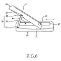
FIG. 6 is a side sectional view showing the sliding and rotation of a second housing of a portable communication apparatus according to an exemplary embodiment of the present invention; -
FIG. 7 is a perspective view showing a second housing of a portable communication apparatus according to an exemplary embodiment of the present invention, after it has been operated; and -
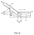
FIG. 8 is a side sectional view showing a second housing of a portable communication apparatus according to an exemplary embodiment of the present invention, after it has been operated. - Throughout the drawings, the same reference numerals will be understood to refer to the same elements, features, and structures.
- The matters defined in the description such as a detailed construction and elements are provided to assist in a comprehensive understanding of the exemplary embodiments of the invention and are merely exemplary. Accordingly, those of ordinary skill in the art will recognize that various changes and modifications of the exemplary embodiments described herein can be made without departing from the scope and spirit of the invention. Also, descriptions of well-known functions and constructions are omitted for clarity and conciseness.
- An exemplary embodiment of the present invention will now be described in detail with reference to the annexed drawings.
- As shown in
FIGs. 1 and2 , aportable communication apparatus 10 includes afirst housing 20, asecond housing 30, a guide means 40, and a rotational moving means 50. Thefirst housing 20 extends in a longitudinal direction to face thesecond housing 30 and thesecond housing 30 is positioned on thefirst housing 20 such that it slides substantially perpendicularly to the longitudinal direction and rotates to stand at a desired angle. The guide means 40 is included in both ends of thefirst housing 20 to guide the sliding movement of thesecond housing 30. The rotational moving means 50 is included between thefirst housing 20 and thesecond housing 30 to rotate in such a way to make thesecond housing 30 stand at a desired angle. - As shown in
FIGs. 1 and4 , amounting face 21 recessed to a predetermined depth is formed on thefirst housing 20 to allow the second housing to be mounted thereon and allow thesecond housing 30 to slide and rotate with respect to thefirst housing 20. Themounting face 21 has a curved surface to facilitate sliding and rotation of thesecond housing 30. - As shown in
FIGs. 1 and7 , thefirst housing 20 includes akeypad 22 including a plurality ofkeys 22a. Thekeypad 22 is opened or closed by sliding thesecond housing 30. Thesecond housing 30 includes a Liquid Crystal Display (LCD) 31 to facilitate watching TV and moving pictures. - As shown in
FIGs. 1 ,2 ,4 ,6 , and8 , the guide means 40 includes a pair ofguide members 41 andguide holes 42. Theguide members 41 are formed at both ends of thesecond housing 30 to be slidably combined with theguide holes 42. Theguide holes 42 are substantially perpendicular to the longitudinal direction of thefirst housing 20 so that theguide members 41 may slide within theguide holes 42 and rotate with respect to a rotation axis A1. - As shown in
FIG. 5 , thefirst housing 20 includesspeaker devices 23 and amicrophone device 24. - As shown in
FIGs. 4 ,6 , and8 , the rotational moving means 50 includes alink member 53 to allow thesecond housing 30 to be folded or rotated so that thesecond housing 30 is angled with respect to a first link rotation axis L1 and a second link rotation axis L2 during sliding of thesecond housing 30. Afirst end 51 of thelink member 53 provides the first link rotation axis L1 and can be rotatably combined with a pair oflink arms 25 formed in thefirst housing 20. Asecond end 52 of thelink member 53 provides the second link rotation axis L2 and can be rotatably combined with the back side of thesecond housing 30. Aresting groove 32 is formed in the back side of thesecond housing 30 to rest thelink member 53 thereon according to the sliding and rotation of thesecond housing 30. - The operation of the
portable communication apparatus 10 according to an exemplary embodiment of the present invention will be described in more detail with reference toFIGs. 1 through 8 . - As shown in
FIGs. 1 and2 , theportable communication apparatus 10 includes thefirst housing 20 extending in a longitudinal direction, thesecond housing 30, the guide means 40, and the rotational moving means 50. - The mounting
face 21 is formed on thefirst housing 20 to allow thesecond housing 30 to face thefirst housing 20, and thesecond housing 30 is mounted on the mountingface 21 of thefirst housing 20 in opposition to thefirst housing 20. - The pair of
guide members 41 formed in thesecond housing 30 are slidably and rotatably combined with the guide holes 42 formed in thefirst housing 20. - In this state, as shown in
FIG. 2 , the rotational moving means 50 is located between thefirst housing 20 and thesecond housing 30. - The rotational moving means 50 includes the
link member 53. Thelink member 53 rests on the restinggroove 32 formed in the back side of thesecond housing 30. - The
first end 51 of thelink member 53 is rotatably combined with the pair oflink arms 25 formed in thefirst housing 20 and thesecond end 52 of thelink member 53 is rotatably combined with the back side of thesecond housing 30. - In this state, as shown in
FIGs. 3 ,5 , and7 , when watching TV and moving pictures using theportable communication apparatus 10, a user pushes thesecond housing 30 substantially perpendicularly to the longitudinal direction of thefirst housing 20 to slide thesecond housing 30. - As shown in
FIGs. 4 and6 , theguide member 41 of thesecond housing 30 moves within theguide hole 42 of thefirst housing 20. - As shown in
FIGs. 5 and7 , thesecond housing 30 slides along the curve of the mountingface 21 and thesecond housing 30 is supported at a desired angle with respect to thefirst housing 20 by thelink member 53. When theguide member 41 of thesecond housing 30 slides, it also rotates with respect to the rotation axis A1 of theguide hole 42. - In this state, as shown in
FIGs. 4 and6 , if thesecond housing 30 further slides, thelink member 53 rotates with respect to the first link rotation axis L1 and the second link rotation axis L2 and, at the same time, stands at an angle. At this time, thesecond housing 30 also stands. - As shown in
FIGs. 7 and8 , if thesecond housing 30 slides and rotates, thelink member 53 also rotates and makes thesecond housing 30 stand at a desired angle. At this time, thelarge LCD 31 of thesecond housing 30 also stands. - In this state, the user can watch TV and moving pictures using the
large LCD 31. - At this time, the
keypad 22 composed of the plurality ofkeys 22a included in thefirst housing 20 is opened. - The user can listen to audio through the
speaker devices 23 formed at both ends of thefirst housing 20. - The user can also use a communication mode using the
first housing 20 with themicrophone device 24 and thesecond housing 30. - As shown in
FIGs. 2 and3 , to return thesecond housing 30 to its original position, thesecond housing 30 is slid in a reverse direction. The standinglink member 53 rotates with respect to the first link rotation axis L1 and the second link rotation axis L2 and is folded down, and thesecond housing 30 is also folded down. At this time, theguide member 41 slides within theguide hole 42 and thus returns to its original position. - In addition, as shown in
FIGs. 1 ,3 ,5 , and7 , a driving unit (not shown) that is rotatably combined with thelink member 53 of the rotational moving means is included in thefirst housing 20 and aswitch unit 70 that is electrically connected with the driving unit (not shown) is provided in the exterior of thefirst housing 20. The driving unit (not shown) is actuated by pressing theswitch unit 70 to rotate thelink member 53 of the rotational moving means and make thesecond housing 30 automatically stand at a desired angle. - Since the link member can rotate and stand at a desired angle by sliding the second housing, the user can easily make the portable communication apparatus stand and can easily watch TV and moving pictures using the LCD.
- While the invention has been shown and described with reference to certain exemplary embodiments thereof, it will be understood by those skilled in the art that various changes in form and details may be made therein without departing from the scope of the invention as defined by the appended claims.
Claims (9)
- A portable communication apparatus comprising:a first housing (20) extending in a longitudinal direction;a second housing (30) that slides substantially perpendicularly to the longitudinal direction and rotates to stand at an angle with respect to the longitudinal direction;a guide means (40) that guides the sliding movement of the second housing;a rotational moving means (50) between the first housing (20) and the second housing (30) that rotates to make the second housing stand at the angle, the rotational moving means (50) including a link member (53) to allow the second housing (30) to be folded or rotated at an angle with respect to a first link rotation axis L1 and a second link rotation axis L2 during sliding of the second housing (30), characterized in that the second housing includes a resting groove (32) for resting the link member (53).
- The portable communication apparatus of claim 1, wherein a first end (51) of the link member provides the first link rotation axis L1 and is rotatably combined with a pair of link arms (25) formed in the first housing and a second end (52) of the link member provides the second link rotation axis L2 and is rotatably combined with the back side of the second housing (30).
- The portable communication apparatus of claims 1 or 2, further comprising a driving unit in the first housing (20) and a switch unit (70) for actuating the driving unit by being pressed to automatically rotate the rotational moving means (50).
- The portable communication apparatus of one of the claims 1 to 3, wherein the guide means (40) comprises:a pair of guide holes (42) at both ends of the first housing (20), the pair of guide holes being substantially perpendicular to the longitudinal direction of the first housing;a pair of guide members (41) on the second housing, the pair of guide means being slidably combined with the pair of guide holes (42) and rotating with respect to a rotation axis during sliding.
- The portable communication apparatus of one of the claims 1 to 4, wherein the first housing (20) includes a recessed mounting face (21) for accommodating the second housing (30).
- The portable communication apparatus of claim 5, wherein the mounting face (21) has a curved surface.
- The portable communication apparatus of one of the claims 1 to 6, wherein the first housing (20) comprises a keypad (22) composed of a plurality of keys and the keypad is opened and closed by sliding the second housing (30).
- The portable communication apparatus of one of the claims 1 to 7, wherein the second housing includes a Liquid Crystal Display LCD (31).
- The portable communication apparatus of one of the claims 1 to 8, wherein the first housing includes a speaker device (23) and a microphone device (24).
Applications Claiming Priority (1)
| Application Number | Priority Date | Filing Date | Title |
|---|---|---|---|
| KR1020050094358A KR100713411B1 (en) | 2005-10-07 | 2005-10-07 | Communication portable device |
Publications (2)
| Publication Number | Publication Date |
|---|---|
| EP1773031A1 EP1773031A1 (en) | 2007-04-11 |
| EP1773031B1 true EP1773031B1 (en) | 2011-12-07 |
Family
ID=37667693
Family Applications (1)
| Application Number | Title | Priority Date | Filing Date |
|---|---|---|---|
| EP06021026A Expired - Fee Related EP1773031B1 (en) | 2005-10-07 | 2006-10-06 | Portable communication apparatus with display positionable at an angle |
Country Status (4)
| Country | Link |
|---|---|
| US (1) | US8666463B2 (en) |
| EP (1) | EP1773031B1 (en) |
| KR (1) | KR100713411B1 (en) |
| CN (1) | CN101005523A (en) |
Families Citing this family (17)
| Publication number | Priority date | Publication date | Assignee | Title |
|---|---|---|---|---|
| KR100678215B1 (en) * | 2006-04-07 | 2007-02-02 | 삼성전자주식회사 | Mobile phone and sliding-cradling apparatus thereof |
| TWI496449B (en) * | 2008-01-09 | 2015-08-11 | Asustek Comp Inc | Mobile phone with camera |
| KR101417814B1 (en) * | 2008-02-29 | 2014-07-09 | 삼성전자주식회사 | Digital photographing apparatus |
| WO2009153388A1 (en) * | 2008-06-18 | 2009-12-23 | Nokia Corporation | A device with a turning functional module |
| TWI344813B (en) * | 2008-11-12 | 2011-07-01 | Htc Corp | Portable electronic device |
| TWI359353B (en) * | 2009-05-19 | 2012-03-01 | Htc Corp | Handheld electronic device |
| CN101902889B (en) * | 2009-05-26 | 2012-12-05 | 宏达国际电子股份有限公司 | Handheld electronic device |
| KR101035161B1 (en) * | 2009-11-09 | 2011-05-17 | 주식회사 팬택 | A terminal and sliding apparatus |
| TWI401560B (en) * | 2009-11-24 | 2013-07-11 | Htc Corp | Electronic device |
| US8363391B2 (en) * | 2010-01-26 | 2013-01-29 | Samsung Electronics Co., Ltd. | Portable terminal |
| US8725223B2 (en) * | 2010-02-08 | 2014-05-13 | Nokia Corporation | Apparatus for a portable electronic device |
| KR101695989B1 (en) * | 2010-11-01 | 2017-01-13 | 삼성전자주식회사 | Portable terminal |
| KR101750117B1 (en) | 2011-01-10 | 2017-06-22 | 삼성전자주식회사 | Cradling apparatus for portable communication device |
| TWI463938B (en) * | 2011-01-27 | 2014-12-01 | Htc Corp | Tiltable linkage mechanism |
| US10234908B2 (en) * | 2014-04-29 | 2019-03-19 | Hewlett-Packard Develoment Company, L.P. | Hinge assembly for a computing device |
| US20170265622A1 (en) * | 2016-03-15 | 2017-09-21 | HCT Group Holdings Limited | Double fold compact |
| KR20210082026A (en) * | 2019-12-24 | 2021-07-02 | 삼성전자주식회사 | Electronic device including display and operation method of the same |
Citations (1)
| Publication number | Priority date | Publication date | Assignee | Title |
|---|---|---|---|---|
| US20030109230A1 (en) * | 2001-08-29 | 2003-06-12 | Matias Duarte | Sliding display apparatus |
Family Cites Families (11)
| Publication number | Priority date | Publication date | Assignee | Title |
|---|---|---|---|---|
| KR200180373Y1 (en) | 1999-10-14 | 2000-05-01 | 조찬욱 | Stay for cellular phone |
| FI19992510A (en) * | 1999-11-24 | 2001-05-25 | Nokia Mobile Phones Ltd | Electronic device and method in the electronic device |
| US7224373B1 (en) * | 2000-04-07 | 2007-05-29 | Danger, Inc. | Adjustable data processing display |
| FI118073B (en) * | 2000-08-03 | 2007-06-15 | Nokia Corp | Portable, at least two modes of use including foldable electronic device and hinged mechanism therefor |
| US6850226B2 (en) * | 2001-11-09 | 2005-02-01 | Nokia Corporation | Multifunction mobile communications device with slidable display screen |
| KR20040096167A (en) * | 2003-05-07 | 2004-11-16 | 주식회사 팬택 | Folding type sliding mobile terminal |
| KR100531880B1 (en) | 2003-07-10 | 2005-11-29 | 엘지전자 주식회사 | Sliding device in sliding type mobile phone |
| KR100703339B1 (en) * | 2003-09-24 | 2007-04-03 | 삼성전자주식회사 | Sliding type portable wireless terminal and method for controlling sliding operation therein |
| US7636748B2 (en) * | 2003-09-29 | 2009-12-22 | Microsoft Corporation | Display configurations for a data processing device |
| US7495700B2 (en) | 2004-04-05 | 2009-02-24 | Casio Computer Co., Ltd. | Moving image capture device, moving image capture control method, and moving image capture control program |
| TWM263698U (en) * | 2004-10-04 | 2005-05-01 | Hith Tech Comp Corp | Portable electronic apparatus with dual operations |
-
2005
- 2005-10-07 KR KR1020050094358A patent/KR100713411B1/en not_active IP Right Cessation
-
2006
- 2006-09-28 CN CNA2006101598200A patent/CN101005523A/en active Pending
- 2006-09-29 US US11/529,497 patent/US8666463B2/en not_active Expired - Fee Related
- 2006-10-06 EP EP06021026A patent/EP1773031B1/en not_active Expired - Fee Related
Patent Citations (1)
| Publication number | Priority date | Publication date | Assignee | Title |
|---|---|---|---|---|
| US20030109230A1 (en) * | 2001-08-29 | 2003-06-12 | Matias Duarte | Sliding display apparatus |
Also Published As
| Publication number | Publication date |
|---|---|
| US8666463B2 (en) | 2014-03-04 |
| KR20070039247A (en) | 2007-04-11 |
| KR100713411B1 (en) | 2007-05-04 |
| CN101005523A (en) | 2007-07-25 |
| EP1773031A1 (en) | 2007-04-11 |
| US20070082695A1 (en) | 2007-04-12 |
Similar Documents
| Publication | Publication Date | Title |
|---|---|---|
| EP1773031B1 (en) | Portable communication apparatus with display positionable at an angle | |
| US7813775B2 (en) | Portable terminal foldable to form a triangular prism | |
| KR100630024B1 (en) | Portable phone with rotational display unit and hinge device thereof | |
| US8250712B2 (en) | Hinge device having a plurality of axes for a portable terminal and a connection member having the plurality of axes | |
| US7526325B2 (en) | Triple-axis rotation folder-type portable apparatus | |
| FI118073B (en) | Portable, at least two modes of use including foldable electronic device and hinged mechanism therefor | |
| FI118621B (en) | Portable, foldable electronic device with open and closed operating position and handle arrangement | |
| US20070039132A1 (en) | Hinge device for portable terminal and portable terminal having the same | |
| US8380257B2 (en) | Swing-type mobile communication terminal and swing device thereof | |
| EP1675362A2 (en) | Foldable phone with a rotatable 3rd housing between the 2 folding housings | |
| EP1773030A2 (en) | Foldable portable terminal with a hinge which allows several angle positions of the two housings | |
| US7859585B2 (en) | Portable terminal having camera lens assembly | |
| KR100630138B1 (en) | Hinge device for portable terminal | |
| EP1848183B1 (en) | Hinge device for portable terminal | |
| JP4974079B2 (en) | Foldable communication terminal | |
| KR100842627B1 (en) | Portable terminal | |
| KR100700567B1 (en) | Portable terminal | |
| KR200402885Y1 (en) | Mobile communication terminal of slide type | |
| JP2003169120A (en) | Portable terminal device | |
| KR100651538B1 (en) | Portable terminal | |
| KR100598401B1 (en) | Mobile Display Device | |
| US8103320B2 (en) | Portable terminal for providing visual and acoustic convenience and rotary type hinge apparatus therefor | |
| JP2007110589A (en) | Mobile communication apparatus |
Legal Events
| Date | Code | Title | Description |
|---|---|---|---|
| PUAI | Public reference made under article 153(3) epc to a published international application that has entered the european phase |
Free format text: ORIGINAL CODE: 0009012 |
|
| 17P | Request for examination filed |
Effective date: 20061006 |
|
| AK | Designated contracting states |
Kind code of ref document: A1 Designated state(s): AT BE BG CH CY CZ DE DK EE ES FI FR GB GR HU IE IS IT LI LT LU LV MC NL PL PT RO SE SI SK TR |
|
| AX | Request for extension of the european patent |
Extension state: AL BA HR MK YU |
|
| 17Q | First examination report despatched |
Effective date: 20071005 |
|
| AKX | Designation fees paid |
Designated state(s): DE FR GB |
|
| GRAP | Despatch of communication of intention to grant a patent |
Free format text: ORIGINAL CODE: EPIDOSNIGR1 |
|
| GRAS | Grant fee paid |
Free format text: ORIGINAL CODE: EPIDOSNIGR3 |
|
| GRAA | (expected) grant |
Free format text: ORIGINAL CODE: 0009210 |
|
| AK | Designated contracting states |
Kind code of ref document: B1 Designated state(s): DE FR GB |
|
| REG | Reference to a national code |
Ref country code: GB Ref legal event code: FG4D |
|
| REG | Reference to a national code |
Ref country code: DE Ref legal event code: R096 Ref document number: 602006026235 Country of ref document: DE Effective date: 20120202 |
|
| RAP2 | Party data changed (patent owner data changed or rights of a patent transferred) |
Owner name: SAMSUNG ELECTRONICS CO., LTD. |
|
| PLBE | No opposition filed within time limit |
Free format text: ORIGINAL CODE: 0009261 |
|
| STAA | Information on the status of an ep patent application or granted ep patent |
Free format text: STATUS: NO OPPOSITION FILED WITHIN TIME LIMIT |
|
| 26N | No opposition filed |
Effective date: 20120910 |
|
| REG | Reference to a national code |
Ref country code: DE Ref legal event code: R097 Ref document number: 602006026235 Country of ref document: DE Effective date: 20120910 |
|
| REG | Reference to a national code |
Ref country code: FR Ref legal event code: PLFP Year of fee payment: 11 |
|
| REG | Reference to a national code |
Ref country code: FR Ref legal event code: PLFP Year of fee payment: 12 |
|
| PGFP | Annual fee paid to national office [announced via postgrant information from national office to epo] |
Ref country code: GB Payment date: 20170928 Year of fee payment: 12 Ref country code: FR Payment date: 20170925 Year of fee payment: 12 |
|
| PGFP | Annual fee paid to national office [announced via postgrant information from national office to epo] |
Ref country code: DE Payment date: 20170921 Year of fee payment: 12 |
|
| REG | Reference to a national code |
Ref country code: DE Ref legal event code: R119 Ref document number: 602006026235 Country of ref document: DE |
|
| GBPC | Gb: european patent ceased through non-payment of renewal fee |
Effective date: 20181006 |
|
| PG25 | Lapsed in a contracting state [announced via postgrant information from national office to epo] |
Ref country code: DE Free format text: LAPSE BECAUSE OF NON-PAYMENT OF DUE FEES Effective date: 20190501 |
|
| PG25 | Lapsed in a contracting state [announced via postgrant information from national office to epo] |
Ref country code: FR Free format text: LAPSE BECAUSE OF NON-PAYMENT OF DUE FEES Effective date: 20181031 |
|
| PG25 | Lapsed in a contracting state [announced via postgrant information from national office to epo] |
Ref country code: GB Free format text: LAPSE BECAUSE OF NON-PAYMENT OF DUE FEES Effective date: 20181006 |