EP1768233B1 - Airgap sleeve - Google Patents
Airgap sleeve Download PDFInfo
- Publication number
- EP1768233B1 EP1768233B1 EP05020867A EP05020867A EP1768233B1 EP 1768233 B1 EP1768233 B1 EP 1768233B1 EP 05020867 A EP05020867 A EP 05020867A EP 05020867 A EP05020867 A EP 05020867A EP 1768233 B1 EP1768233 B1 EP 1768233B1
- Authority
- EP
- European Patent Office
- Prior art keywords
- impeller
- pump assembly
- assembly according
- axial
- metallic material
- Prior art date
- Legal status (The legal status is an assumption and is not a legal conclusion. Google has not performed a legal analysis and makes no representation as to the accuracy of the status listed.)
- Active
Links
Images

Classifications
-
- H—ELECTRICITY
- H02—GENERATION; CONVERSION OR DISTRIBUTION OF ELECTRIC POWER
- H02K—DYNAMO-ELECTRIC MACHINES
- H02K5/00—Casings; Enclosures; Supports
- H02K5/04—Casings or enclosures characterised by the shape, form or construction thereof
- H02K5/12—Casings or enclosures characterised by the shape, form or construction thereof specially adapted for operating in liquid or gas
- H02K5/128—Casings or enclosures characterised by the shape, form or construction thereof specially adapted for operating in liquid or gas using air-gap sleeves or air-gap discs
- H02K5/1285—Casings or enclosures characterised by the shape, form or construction thereof specially adapted for operating in liquid or gas using air-gap sleeves or air-gap discs of the submersible type
-
- F—MECHANICAL ENGINEERING; LIGHTING; HEATING; WEAPONS; BLASTING
- F04—POSITIVE - DISPLACEMENT MACHINES FOR LIQUIDS; PUMPS FOR LIQUIDS OR ELASTIC FLUIDS
- F04D—NON-POSITIVE-DISPLACEMENT PUMPS
- F04D13/00—Pumping installations or systems
- F04D13/02—Units comprising pumps and their driving means
- F04D13/06—Units comprising pumps and their driving means the pump being electrically driven
- F04D13/0606—Canned motor pumps
- F04D13/0626—Details of the can
-
- F—MECHANICAL ENGINEERING; LIGHTING; HEATING; WEAPONS; BLASTING
- F04—POSITIVE - DISPLACEMENT MACHINES FOR LIQUIDS; PUMPS FOR LIQUIDS OR ELASTIC FLUIDS
- F04D—NON-POSITIVE-DISPLACEMENT PUMPS
- F04D13/00—Pumping installations or systems
- F04D13/02—Units comprising pumps and their driving means
- F04D13/06—Units comprising pumps and their driving means the pump being electrically driven
- F04D13/0606—Canned motor pumps
- F04D13/0633—Details of the bearings
-
- H—ELECTRICITY
- H02—GENERATION; CONVERSION OR DISTRIBUTION OF ELECTRIC POWER
- H02K—DYNAMO-ELECTRIC MACHINES
- H02K21/00—Synchronous motors having permanent magnets; Synchronous generators having permanent magnets
- H02K21/12—Synchronous motors having permanent magnets; Synchronous generators having permanent magnets with stationary armatures and rotating magnets
Definitions
- the invention relates to a pump unit with a wet-running electric motor.
- split tubes have the disadvantage that small amounts of fluid diffuse through the can through into the stator space. For this reason, such split tubes can not be used, in particular in submersible pumps in which there is no possibility to discharge the fluid from the stator space. In such pumps, it has hitherto been compulsory to use metal cans which worsen the efficiency of the pump, or the stator has to be cast with a casting compound which takes up the fluid or protects the windings.
- the document EP-A-0 658 967 describes a magnetic coupling between a motor and a pump housing.
- the split pot described there is made of carbon fiber reinforced plastic and has a coating consisting of amorphous carbon. As a result, the sliding friction between the pot and the other substances occurring in the magnetic centrifugal pump should be reduced as much as possible.
- the pump unit according to the invention has a can of a non-metallic material, d. H. made of a material which influences the magnetic field between rotor and stator as little as possible or not.
- the non-metallic material of the can is provided with at least one additionally hermetically sealing layer in the form of a metallization.
- Such an additional layer which is preferably applied to the outer or the inner peripheral surface or to both peripheral surfaces, makes it possible to use a material for the split tube which does not have sufficient diffusion tightness per se. That is, it can be a material to be selected, which ensures primarily a sufficient stability of the can.
- the coating is formed as a metallization of the non-metallic material. That is, on the inner and / or outer peripheral surface of the can, a metal layer is applied, for example vapor-deposited. This metal layer then ensures the hermetic seal.
- the coating of the non-metallic material for example by metallization with a suitable metal, is expediently such that the entire circumferential surface, which forms the separation between the rotor space in the interior of the can and the surrounding stator space, is coated accordingly, so that there is no fluid in this area For example, water from the interior of the can through the Spaltrohrwandung can penetrate into the surrounding stator space.
- the can is made of plastic and preferably a fiber-reinforced plastic.
- Plastic allows cost-effective production of the can, for example by injection molding. Furthermore, plastic has no magnetic properties and therefore does not affect the magnetic field between the stator and the rotor. Furthermore, plastic can be suitably coated or provided with further surrounding and internal plastic layers, in the manner of coextrusion. Even a metallization of plastic is easily possible.
- the fiber-reinforced construction can improve the stability or pressure resistance of the can.
- the split tube is made of a tubular member and a bottom member which closes the tubular member at a first axial end.
- This allows a simplified production of the can, which allows, for example, the production of thin-walled plastic split tubes by injection molding.
- injection molding of the can it may be appropriate that a core forming the cavity in the interior of the can is held at both axial ends of the can in order to achieve a very thin-walled design of the can.
- the tubular component is manufactured and then later the bottom element is inserted into this tubular component in order to close an axial opening of the tubular component and to form a canned pot.
- the opposite axial side of the can is open, so that the rotor shaft can extend to the pump space through this axial side.
- the bottom element can force, shape and / or cohesive in the tubular member be inserted so that a solid stable and preferably tight connection between the tubular member and the bottom element is provided.
- the bottom element is potted with the tubular component.
- the bottom element in a second manufacturing step by injection molding on the tubular member molded or molded or poured into the tubular member, so that a permanent tight connection between the two elements is created.
- the tubular component and the bottom element are more preferably both made of a non-metallic material, preferably plastic and provided after assembly together with the additional layer or coating.
- the region of the base element and in particular the transition region between the tubular component and the base element are also hermetically sealed by the coating.
- the tubular component and the bottom element can be metallized together.
- the additional layer can be attached to the floor element separately or integrated into this.
- a radially outwardly extending, preferably metallic, collar is formed on the outer circumference at an axial end of the can, preferably on the end facing the pump space and the impeller of the pump.
- This metallic collar is used for.
- the stator housing is preferably hermetically encapsulated, in particular when used in a submersible pump, so that no fluid can penetrate into the interior of the stator housing. Thus, the coils are protected inside the stator housing in particular from moisture.
- the metallic collar which is mounted on the outer circumference of the can, serves to connect to the outer parts of the stator housing and allows the can to be welded to the rest of the stator housing.
- the collar is preferably positively and / or materially connected to the non-metallic material and provided together with this with the additional layer or coating.
- a non-positive connection is conceivable, provided sufficient strength and tightness is ensured.
- the common coating of the non-metallic material of the can and of the collar has the advantage that in particular the transition region between the non-metallic material and the collar is hermetically sealed by the coating. In order to ensure a permanent seal in this area, a particularly strong connection between the metallic collar and the non-metallic material of the split tube is preferred, so that movements between the two elements, which could lead to cracking of the coating, are avoided.
- the metallic collar is preferably connected directly to the non-metallic material during manufacture of the can.
- the metallic collar can be inserted into the mold before injection molding and the plastic injection molded onto the collar or a part of the collar are molded with plastic, so that directly in injection molding a positive and fluid connection is achieved between both elements.
- a surface of the collar preferably becomes structured or roughened before the connection with the non-metallic material of the can. This can be done for example by laser irradiation, wherein by means of a laser beam small depressions and / or crater-shaped elevations are introduced into the surface of the collar into which flows the non-metallic material, such as plastic during casting and thus on the one hand over a larger surface and on the other a positive connection establishes a firm connection with the collar.
- the electric motor is preferably a permanent magnet motor, i. the rotor is equipped with permanent magnets.
- the rotor is equipped with permanent magnets.
- neodynium magnets are preferably used.
- the combination of permanent magnets with the non-metallic can has the advantage that a high efficiency of the motor can be achieved even by means of a permanent magnet rotor, since the can only little or no effect on the magnetic field.
- the pump unit is designed as a submersible pump unit.
- the hermetically sealed can according to the invention has particular advantages. Especially with submersible pump units, it is important to prevent fluid, in particular moisture from penetrating the rotor space in the stator, since there is no way to vaporize the moisture in the stator by the heat of the engine, since the stator is hermetically sealed on the outside.
- an impeller of the pump unit by the electric motor with a maximum speed greater than 20,000 U / min driven and the impeller axially sealed in the region of the suction.
- the speed can also be greater than 25,000 or 30,000 rpm.
- the high speed allows a high flow rate of the pump with a small diameter impeller.
- the small diameter of the impeller allows friction and thus minimize the losses of the pump unit.
- the axial sealing of the suction mouth has the advantage that the axial surface of the impeller can simultaneously serve as a sealing surface, so that the number of required sealing elements is reduced, and a simple seal in the region of the suction mouth can be formed. This further enables the friction in the pump unit and thus to minimize the power loss.
- At least one axial end face of the impeller particularly preferably forms an axial bearing surface.
- the bearing surface simultaneously serves as an axial sealing surface. This has the further advantage that no additional pressure elements are required to hold the seal in abutment.
- the thrust bearing which forms a sliding bearing, automatically sets a sufficiently small gap, which ensures a reliable seal and at the same time ensures a sufficient lubricating film on the bearing surface.
- the gap is preferably in the range of a few micrometers. This ensures a particularly good seal at the suction mouth, which further contributes to increase the efficiency of the pump unit.
- the impeller is fixed on the rotor shaft in the axial direction, so that the impeller can take over the axial bearing function of the entire rotor. That is, the axial bearing of the entire rotor takes place on the impeller, preferably in a sliding bearing, whose thrust bearing surface is formed by the axial end face of the impeller, preferably from the axial end faces of the impeller blades.
- cemented carbide and ceramic or for surface coating with cemented carbide or ceramic it is also possible to use other processes or coatings for surface hardening of the impeller, provided that a sufficient wear resistance of the surfaces is achieved.
- a hardness of the impeller surface is preferably greater than 1000 HV.
- the design of the impeller completely made of hard metal or ceramic can be carried out, for example, in the sintering process, wherein the impeller blades are then preferably ground to form the end faces of the impeller blades as defined Axiallager- and sealing surface. If the opposite end face of the impeller is also to be formed as a sealing surface, these are also preferably ground to create a defined contact surface.
- the pump unit according to the invention particularly preferably has only one step.
- the number of required items is significantly reduced.
- the friction occurring throughout the pump unit is reduced, whereby the efficiency can be increased.
- the overall reduced friction makes it possible to operate the entire pump unit at high speed, for example greater than 20,000 rpm, whereby a high delivery rate can be achieved even with only one stage.
- the impeller in its diameter very small form, whereby the power loss is further reduced and at the same time the operation is promoted at high speed.
- the diameter of the rotor is formed very small, which can be achieved by particularly strong permanent magnets and high efficiency of the electric motor, whereby the friction losses in the engine can be minimized and the high-speed operation is favored.
- the rotor diameter is less than 25 mm, more preferably less than 20 mm. The smaller the rotor diameter, the lower the friction that occurs.
- a counter-rotating disc facing the impeller is provided, which abuts on an axial side of the impeller, preferably the axial side facing away from the electric motor, in such a way that it forms an axial bearing surface.
- a sliding bearing is formed between the axial end face of the impeller or the impeller blades and the mating disk, which can serve as a thrust bearing of the impeller and the entire rotor.
- the counter-rotating disc preferably also has at least one surface made of hard metal or ceramic material in order to provide the wear characteristics required for a sliding bearing and sealing surface to ensure even at high speeds. It is also possible to form the counter-rotating disc completely made of hard metal or ceramic material. Particularly preferred only the impeller facing part of the counter-rotating disk is formed from such a material. The part facing away from the impeller may be formed of a different material or metal and be glued to the impeller facing part, for example. Alternative methods or designs which ensure a sufficient hardness or wear resistance of the surface of the counter-rotating disc can also be used here.
- the impeller is surrounded by a spiral housing or diffuser, whereby the radially discharged from the impeller funded fluid is deflected so that it can be preferably forwarded in the axial direction and out of the pump unit in a connecting line.
- the impeller is surrounded by a spiral housing, which extends helically so that the outlet opening of the spiral housing in the axial direction to the impeller, that is aligned parallel to its axis of rotation. This causes the fluid, which in tangential / radial direction from the impeller exits, is deflected by the volute as lossless as possible to an axially directed outlet opening of the pump unit.
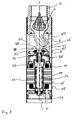
- Fig. 1 shows a sectional view of the upper end of a submersible pump.
- the lower end in which the electronics for controlling the pump is mounted, is not shown in the figure.
- the pump unit has at its upper end a connecting piece 2 with a non-return valve 4 arranged therein.
- a spiral housing 6, which surrounds the impeller 8, adjoins the inside of the pump assembly upstream.
- the impeller 8 is arranged at the axial end of the integral rotor shaft 10 of the electric motor 11 or its permanent magnet rotor 12.
- the impeller 8 is fixedly fixed to the rotor shaft 10, in particular in the axial direction X firmly connected.
- the permanent magnet rotor 12 runs inside a split tube 14 which is annular at its outer periphery surrounded by the stator 16.
- the stator 16 is formed in a known manner as a laminated core with coil windings.
- the stator 16 is hermetically sealed in total in a stator housing 18.
- the rotor shaft 10 is mounted in two radial bearings 20 in the radial direction. These radial bearings 20 are preferably self-centering, so that easy assembly and safe operation is ensured even at high speeds.
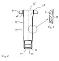
- the bottom member 30 may be manufactured separately and later inserted into the tubular member 22. As shown, a positive connection between bottom element 30 and tubular component 22 is produced in that the inwardly bent axial peripheral edge of the tubular component 22 engages in a circumferential groove 32 of the bottom element 30.
- a collar 34 is attached to the outer circumference of the tubular member 22.
- the collar 34 is made of metal, preferably stainless Stainless steel formed and annular, with its inner diameter is matched to the outer diameter of the tubular member 22 at the axial end 26.
- the ring of the collar 34 has a U-shaped cross-section, wherein the transverse leg faces the axial end 26.
- the inner wall 36 of the collar 34 abuts parallel to the peripheral wall of the tubular member 22 and is connected thereto.
- the gap tube 14 thus created is metallized.
- a thin metal layer 38 is applied to the outer surface of the can 14, as in Fig. 3 shown.
- the metal layer 38 covers the entire outer surface of the tubular member 22 and the bottom member 30 as well the collar 34.
- the transition regions between the collar 34 and the tubular member 22 and between the bottom member 30 and the tubular member 22 are covered by the metal layer 38.
- the metal layer 38 ensures that a hermetic seal of the can 14 and in particular the peripheral wall of the tubular member 22 is provided.
- This hermetic seal through the metal layer 38 causes fluid, which is located in the rotor chamber 28, can not penetrate through the split tube 14 into the interior of the stator housing 18, in which the stator 16 is arranged.
- the metallization or coating 38 allows the use of a plastic for the tubular member 22 and the bottom member 30, which is not diffusion-tight per se. So here the plastic can be selected purely according to the requirements of the stability of the can 14 and according to manufacturing considerations.
- split tube 14 has been described, which is provided on its outside with the metal layer 38.
- metal layer 38 it is also possible to provide the split tube 14 both on its outer side and on the inner surfaces of the inner space 28 with a metal layer by metallization.
- the metallic collar 34 serves to connect the split tube 14 with the remaining part of the stator housing 18. This can be done in particular by a weld 39 on the outer circumference of the metallic collar 34.
- the collar 34 thus provides the connection to other metallic components of which the stator housing 18 is formed, as in FIG Fig. 4 shown.
- the use of the can 14 of plastic, ie a non-metallic material without magnetic properties has the advantage that the split tube 14, the magnetic field between stator 16 and permanent magnet rotor 12 only slightly or not at all, whereby the efficiency of the electric motor 11 is increased.
- the diameter of the permanent magnet rotor 12 and the impeller 8 is kept small in order to minimize the friction in the system and thus the power loss as possible.
- the permanent magnet rotor 12 is equipped with particularly strong permanent magnets, for example neodynium magnets. In the example shown, the rotor diameter is 19 mm.
- the electric motor 11 shown is designed for very high speeds> 20,000, in particular between 25,000 and 30,000 rpm. Thus, with only one impeller 8 with a relatively small diameter, a sufficiently high flow rate can be achieved.
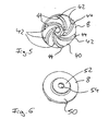
- the impeller 8 which in FIGS. 5 and 6 As an individual part is shown, to ensure a high wear resistance, made of carbide.
- the impeller blades 42 are formed on an axial side 40, which faces away from the electric motor 11 in the installed state.
- the impeller 8 is open, ie the impeller blades project from the axial side 40 of the impeller 8 and are not closed at their end faces 44 by a cover.
- the end faces or end edges 44 of the impeller blades 42 are ground and thus form a Axiallager- and sealing surface of the impeller 8.
- the end faces 44 are in the installed state of a counter-rotating disk 46, which surrounds the suction port 48 of the pump annular. Due to the fixed connection of the impeller 8 with the rotor shaft 10, the entire rotor 12 is supported via the impeller 8 in the axial direction on the counter-rotating disk 46. Ie. the end face of the counter-rotating disc 46, which faces the impeller 8, and the end faces 44 of the Impeller blades 42 form an axial sliding bearing.
- the end faces 44 of the impeller blades 42 are pressed against the mating disk 46 so that there is a particularly good seal between the impeller blades 42 and the counter-rotating disk 46.
- losses in the pump are minimized and the delivery rate of the pump unit is further increased, especially at the high engine speed described above.
- the impeller 8 assumes the a-xial workede seal against the mating disk 46 at the suction port 48 and at the same time the thrust bearing function, so that here the number of components and the friction occurring are minimized.
- the rear side 50 of the impeller 8 facing away from the impeller blades 42 has a further annular sealing surface 52, which annularly surrounds the opening 54 for receiving the rotor shaft.
- the sealing surface 52 bears against a seal 56, which surrounds the rotor shaft 10 fixedly and seals off the rotor chamber 28 in the interior of the can 14 for the pump chamber, in which the impeller 8 is arranged.
- This seal 56 is held by spring action on the sealing surface 52 in abutment.
- the seal 56 ensures that impurities in the fluid, which is conveyed by the impeller 8, do not penetrate into the rotor chamber 28 in the interior of the can 14 and there may lead to undesirable friction or damage.
- the counter-rotating disc 46 is also preferably made of hard metal or ceramic.
- the side facing away from the impeller 8 58 is formed spherically (in Fig. 1 not shown) and mounted in a spherical receptacle in the pump housing, so that the mating disk 46 can align automatically parallel to the impeller 8.
- This part of the counter-disc, which forms the back 58 may consist of a be formed material other than carbide or ceramic and with the part of the counter-rotating disc 46, which faces the impeller 8, be connected, for example by gluing.
- the impeller 8 is circumferentially surrounded by the spiral housing 6.
- the spiral housing 6 extends, starting from the peripheral region of the impeller 8, helically to the connecting piece 2, so that a flow deflection takes place in the axial direction. Ie. the flow, which exits in the radial / tangential direction on the outer circumference of the impeller 8, is first deflected by the volute 6 in a purely tangential direction or circumferential direction of the impeller 8 and then steered in the axial direction as lossless as possible due to the helical winding of the volute 6, so that the flow at the connecting piece 2 in the axial direction can escape from the pump unit.
- the spiral housing 6 is preferably also made of plastic as an injection molded part, the spiral housing 6 includes at its lower, the impeller 8 end facing also the also spherical receptacle for the mating disk 6 and centrally forms the suction port 48 of the pump, through which the fluid by rotation of Impeller 8 is sucked.
- the outer housing of the pump unit has in the region in which the spiral housing 6 is disposed in its outer peripheral wall inlet opening 62, through which the fluid enters from the outside, flows around the spiral housing 6 from the outside and then enters the suction mouth 48 ,
Landscapes
- Engineering & Computer Science (AREA)
- Mechanical Engineering (AREA)
- General Engineering & Computer Science (AREA)
- Power Engineering (AREA)
- Structures Of Non-Positive Displacement Pumps (AREA)
- Motor Or Generator Frames (AREA)
- Acyclic And Carbocyclic Compounds In Medicinal Compositions (AREA)
- Food Preservation Except Freezing, Refrigeration, And Drying (AREA)
Abstract
Description
Die Erfindung betrifft ein Pumpenaggregat mit einem nasslaufenden Elektromotor.The invention relates to a pump unit with a wet-running electric motor.
Es sind verschiedene Arten von Pumpenaggregaten, beispielsweise Heizungsumwölzpumpen und Tauchpumpen, bekannt, welche als Nassläufer ausgebildet sind, d. h. bei denen der Rotor im Fluid läuft. Bei diesen nasslaufenden Elektromotoren ist im Inneren des Stators ein Spaltrohr vorgesehen, welches den Rotorraum, in welchem der Rotor rotiert und welcher Fluid gefüllt ist, zum Stator hin abdichtet. Die Spaltrohre werden häufig aus Metall, insbesondere rostfreien Edelstahl gefertigt. Dies hat jedoch den Nachteil, dass das Magnetfeld zwischen Stator und Rotor beeinträchtigt wird, so dass es zu einer Verschlechterung des Wirkungsgrades des Motors kommt. Ferner sind Spaltrohre aus Kunststoff bekannt, bei welchen dieses Problem nicht auftritt. Diese Spaltrohre haben jedoch den Nachteil, dass geringe Mengen von Fluid durch das Spaltrohr hindurch in den Statorraum diffundieren. Aus diesem Grunde können derartige Spaltrohre insbesondere bei Tauchpumpen, bei welchen keinerlei Möglichkeit besteht, das Fluid aus dem Statorraum abzuleiten, nicht verwendet werden. Bei derartigen Pumpen müssen bislang zwingend Spaltrohre aus Metall eingesetzt werden, welche den Wirkungsgrad der Pumpe verschlechtern, oder der Stator muss mit einer das Fluid aufnehmenden oder die Wicklungen schützenden Vergussmasse vergossen werden.There are various types of pump units, such as Heizungsumwölzpumpen and submersible pumps, known which are designed as wet runners, d. H. where the rotor runs in the fluid. In these wet-running electric motors, a gap tube is provided in the interior of the stator, which seals the rotor space, in which the rotor rotates and which fluid is filled, to the stator. The split tubes are often made of metal, especially stainless steel. However, this has the disadvantage that the magnetic field between the stator and rotor is impaired, so that there is a deterioration in the efficiency of the engine. Furthermore, split tubes made of plastic are known in which this problem does not occur. However, these split tubes have the disadvantage that small amounts of fluid diffuse through the can through into the stator space. For this reason, such split tubes can not be used, in particular in submersible pumps in which there is no possibility to discharge the fluid from the stator space. In such pumps, it has hitherto been compulsory to use metal cans which worsen the efficiency of the pump, or the stator has to be cast with a casting compound which takes up the fluid or protects the windings.
Das Dokument
Es ist Aufgabe der Erfindung ein verbessertes Pumpenaggregat mit einem Spaltrohr zu schaffen, welches zum einen einen höheren Wirkungsgrad des Pumpenaggregates ermöglicht und zum anderen sicher ein Eindringen von Fluid in den Statorraum verhindern.It is an object of the invention to provide an improved pump unit with a split tube, which on the one hand enables a higher efficiency of the pump unit and on the other hand safely prevent penetration of fluid into the stator space.
Diese Aufgabe wird durch ein Pumpenaggregat mit den im Anspruch 1 angegebenen Merkmalen gelöst. Bevorzugte Ausführungsformen ergeben sich aus den zugehörigen Unteransprüchen.This object is achieved by a pump unit having the features specified in claim 1. Preferred embodiments will be apparent from the appended subclaims.
Das erfindungsgemäße Pumpenaggregat weist ein Spaltrohr aus einem nicht metallischen Material auf, d. h. aus einem Material, welches das Magnetfeld zwischen Rotor und Stator möglichst wenig oder nicht beeinflusst. Dadurch, dass das Magnetfeld durch das Spaltrohrmaterial unbeeinflusst bleibt, werden Wirkungsgradverschlechterungen aufgrund der Anordnung des Spaltrohres zwischen Stator und Rotor vermieden. Erfindungsgemäß ist das nicht metallische Material des Spaltrohrs mit zumindest einer zusätzlich hermetisch dichtenden Schicht in Form einer Metallisierung versehen. Eine solche zusätzliche Schicht, welche vorzugsweise an der äußeren oder der inneren Umfangsfläche oder an beiden Umfangsflächen aufgebracht wird, ermöglicht es, für das Spaltrohr einen Werkstoff einzusetzen, welcher für sich allein die ausreichende Diffusionsdichtigkeit nicht aufweist. Das heißt, es kann ein Werkstoff gewählt werden, welcher vorrangig eine ausreichende Stabilität des Spaltrohres gewährleistet.The pump unit according to the invention has a can of a non-metallic material, d. H. made of a material which influences the magnetic field between rotor and stator as little as possible or not. The fact that the magnetic field is unaffected by the canned material, efficiency deterioration due to the arrangement of the can between stator and rotor are avoided. According to the invention, the non-metallic material of the can is provided with at least one additionally hermetically sealing layer in the form of a metallization. Such an additional layer, which is preferably applied to the outer or the inner peripheral surface or to both peripheral surfaces, makes it possible to use a material for the split tube which does not have sufficient diffusion tightness per se. That is, it can be a material to be selected, which ensures primarily a sufficient stability of the can.
Die Beschichtung ist als Metallisierung des nicht metallischen Materials ausgebildet. Das heißt auf die innere und/oder äußere Umfangsfläche des Spaltrohrs wird eine Metallschicht aufgebracht, beispielsweise aufgedampft. Diese Metallschicht sorgt dann für die hermetische Abdichtung. Die Beschichtung des nicht metallischen Materials, beispielsweise durch Metallisierung mit einem geeigneten Metall, erfolgt zweckmäßigerweise so, dass die gesamte Umfangsfläche, welche die Trennung zwischen Rotorraum im Inneren des Spaltrohrs und dem umgebenden Statorraum bildet, entsprechend beschichtet ist, so dass in diesem Bereich keine Fluid, beispielsweise Wasser vom Inneren des Spaltrohrs durch die Spaltrohrwandung hindurch in den umgebenden Statorraum eindringen kann.The coating is formed as a metallization of the non-metallic material. That is, on the inner and / or outer peripheral surface of the can, a metal layer is applied, for example vapor-deposited. This metal layer then ensures the hermetic seal. The coating of the non-metallic material, for example by metallization with a suitable metal, is expediently such that the entire circumferential surface, which forms the separation between the rotor space in the interior of the can and the surrounding stator space, is coated accordingly, so that there is no fluid in this area For example, water from the interior of the can through the Spaltrohrwandung can penetrate into the surrounding stator space.
Die Diffusionsdichtigkeit in der Weise, dass im Inneren des Spaltrohrs, d. h. im Rotorraum befindliches Fluid nicht durch das Spaltrohr hindurch in den Statorraum eindringen kann, wird durch die zusätzliche auf der Oberfläche des nicht metallischen Materials aufgebrachte Schicht erreicht. Es können auch mehrere Schichten verschiedener Materialien in Kombination Verwendung finden, um die gewünschte hermetische Abdichtung zwischen dem Innenraum des Spaltrohres und dem äußeren Umfangsbereich des Spaltrohres zu erzielen. So kann die Spaltrohrwandung mehrschichtig aus dem nicht metallischen Material und einer oder mehreren Schichten weiterer Materialien aufgebaut werden, welche die Diffusionsdichtigkeit gewährleisten.The diffusion-tightness in such a way that in the interior of the can, that is in the rotor chamber fluid can not penetrate through the can through into the stator, is achieved by the additional applied to the surface of the non-metallic material layer. It can also be used in combination with several layers of different materials to achieve the desired To achieve hermetic sealing between the interior of the can and the outer peripheral portion of the can. Thus, the Spaltrohrwandung can be constructed of multi-layer of non-metallic material and one or more layers of other materials that ensure the diffusion-tightness.
Weiter bevorzugt ist die zumindest eine Schicht als Beschichtung an der inneren und/oder äußeren Umfangsfläche des nicht metallischen Materials ausgebildet. Eine solche Beschichtung kann nach der Fertigung bzw. Formgebung des Teils aus nicht metallischem Material auf dessen Oberfläche aufgebracht werden, beispielsweise durch Aufsprühen oder Aufdampfen.More preferably, the at least one layer is a coating on the inner and / or outer peripheral surface of the non-metallic material educated. Such a coating can be applied after the production or molding of the part of non-metallic material on the surface, for example by spraying or vapor deposition.
Besonders bevorzugt ist das Spaltrohr aus Kunststoff und vorzugsweise einem faserverstärkten Kunststoff gefertigt. Kunststoff ermöglicht eine kostengünstige Herstellung des Spaltrohrs, beispielsweise im Spritzgussverfahren. Ferner weist Kunststoff keinerlei magnetische Eigenschaften auf und beeinflusst daher nicht das Magnetfeld zwischen Stator und Rotor. Ferner lässt sich Kunststoff geeignet beschichten bzw. mit weiteren umgebenden und innenliegenden Kunststoffschichten versehen, nach Art des Koexdrudierens. Auch eine Metallisierung von Kunststoff ist problemlos möglich. Der faserverstärkte Aufbau kann die Stabilität bzw. die Druckfestigkeit des Spaltrohres verbessern.Particularly preferably, the can is made of plastic and preferably a fiber-reinforced plastic. Plastic allows cost-effective production of the can, for example by injection molding. Furthermore, plastic has no magnetic properties and therefore does not affect the magnetic field between the stator and the rotor. Furthermore, plastic can be suitably coated or provided with further surrounding and internal plastic layers, in the manner of coextrusion. Even a metallization of plastic is easily possible. The fiber-reinforced construction can improve the stability or pressure resistance of the can.
Bevorzugt ist das Spaltrohr aus einem rohrförmigen Bauteil und einem Bodenelement gefertigt, welches das rohrförmige Bauteil an einem ersten axialen Ende verschließt. Dies ermöglicht eine vereinfachte Fertigung des Spaltrohres, welche beispielsweise auch die Fertigung dünnwandiger Kunststoffspaltrohre im Spritzgussverfahren ermöglicht. Beim Spritzgießen des Spaltrohres kann es zweckmäßig sein, dass ein den Hohlraum im Inneren des Spaltrohrs bildender Kern an beiden axialen Enden des Spaltrohrs gehalten wird, um eine sehr dünnwandige Ausbildung des Spaltrohres zu erzielen. So wird zunächst das rohrförmige Bauteil gefertigt und dann später das Bodenelement in dieses rohrförmige Bauteil eingesetzt, um eine axiale Öffnung des rohrförmigen Bauteiles zu schließen und einen Spaltrohr-Topf zu bilden. Die entgegengesetzte Axialseite des Spaltrohres ist offen ausgebildet, so dass sich durch diese Axialseite die Rotorwelle zum Pumpenraum erstrecken kann. Das Bodenelement kann in das rohrförmige Bauteil kraft-, form- und/oder stoffschlüssig eingesetzt sein, so dass eine feste stabile und vorzugsweise dichte Verbindung zwischen dem rohrförmigen Bauteil und dem Bodenelement geschaffen wird.Preferably, the split tube is made of a tubular member and a bottom member which closes the tubular member at a first axial end. This allows a simplified production of the can, which allows, for example, the production of thin-walled plastic split tubes by injection molding. In injection molding of the can, it may be appropriate that a core forming the cavity in the interior of the can is held at both axial ends of the can in order to achieve a very thin-walled design of the can. Thus, first the tubular component is manufactured and then later the bottom element is inserted into this tubular component in order to close an axial opening of the tubular component and to form a canned pot. The opposite axial side of the can is open, so that the rotor shaft can extend to the pump space through this axial side. The bottom element can force, shape and / or cohesive in the tubular member be inserted so that a solid stable and preferably tight connection between the tubular member and the bottom element is provided.
Besonders bevorzugt ist das Bodenelement mit dem rohrförmigen Bauteil vergossen. Dabei kann nach Fertigung des rohrförmigen Bauteils das Bodenelement in einem zweiten Fertigungsschritt im Spritzgussverfahren an das rohrförmige Bauteil angespritzt bzw. angegossen bzw. in das rohrförmige Bauteil eingegossen werden, so dass eine dauerhafte dichte Verbindung zwischen beiden Elementen geschaffen wird.Particularly preferably, the bottom element is potted with the tubular component. In this case, after manufacture of the tubular component, the bottom element in a second manufacturing step by injection molding on the tubular member molded or molded or poured into the tubular member, so that a permanent tight connection between the two elements is created.
Das rohrförmige Bauteil und das Bodenelement sind weiter bevorzugt beide aus einem nicht metallischen Material, vorzugsweise Kunststoff gefertigt und nach dem Zusammensetzen gemeinsam mit der zusätzlichen Schicht oder Beschichtung versehen. Auf diese Weise wird durch die Beschichtung zusätzlich auch der Bereich des Bodenelementes und insbesondere der Übergangsbereich zwischen rohrförmigen Bauteil und Bodenelement hermetisch gedichtet. Beispielsweise können das rohrförmige Bauteil und das Bodenelement gemeinsam metallisiert werden. Alternativ kann die zusätzliche Schicht an dem Bodenelement auch separat angebracht oder in dieses integriert werden.The tubular component and the bottom element are more preferably both made of a non-metallic material, preferably plastic and provided after assembly together with the additional layer or coating. In this way, the region of the base element and in particular the transition region between the tubular component and the base element are also hermetically sealed by the coating. For example, the tubular component and the bottom element can be metallized together. Alternatively, the additional layer can be attached to the floor element separately or integrated into this.
Gemäß einer weiteren bevorzugten Ausführungsform ist an einem axialen Ende des Spaltrohres, vorzugsweise an dem dem Pumpenraum und dem Laufrad der Pumpe zugewandten Ende, am Außenumfang ein sich radial nach außen erstreckender, vorzugsweise metallischer Kragen ausgebildet. Dieser metallische Kragen dient z. B. dem stirnseitigen Verschluss des Statorgehäuses, in welchem die Statorwicklung angeordnet ist. Das Statorgehäuse ist insbesondere bei Anwendung in einer Tauchpumpe vorzugsweise hermetisch gekapselt, so dass kein Fluid in das Innere des Statorgehäuses eindringen kann. So werden die Spulen im Inneren des Statorgehäuses insbesondere vor Feuchtigkeit geschützt.According to a further preferred embodiment, a radially outwardly extending, preferably metallic, collar is formed on the outer circumference at an axial end of the can, preferably on the end facing the pump space and the impeller of the pump. This metallic collar is used for. B. the frontal closure of the stator housing, in which the stator winding is arranged. The stator housing is preferably hermetically encapsulated, in particular when used in a submersible pump, so that no fluid can penetrate into the interior of the stator housing. Thus, the coils are protected inside the stator housing in particular from moisture.
Der metallische Kragen, welcher am Außenumfang des Spaltrohres angebracht ist, dient der Verbindung mit den äußeren Teilen des Statorgehäuse und ermöglicht das Spaltrohr mit dem übrigen Statorgehäuse zu verschweißen.The metallic collar, which is mounted on the outer circumference of the can, serves to connect to the outer parts of the stator housing and allows the can to be welded to the rest of the stator housing.
Der Kragen ist vorzugsweise mit dem nicht metallischen Material form- und/oder stoffschlüssig verbunden und gemeinsam mit diesem mit der zusätzlichen Schicht oder Beschichtung versehen. Alternativ ist auch eine kraftschlüssige Verbindung denkbar, sofern eine ausreichende Festigkeit und Dichtigkeit gewährleistet wird. Die gemeinsame Beschichtung des nicht metallischen Materials des Spaltrohrs und des Kragens hat den Vorteil, dass durch die Beschichtung insbesondere auch der Übergangsbereich zwischen dem nicht metallischen Material und dem Kragen hermetisch gedichtet wird. Um in diesem Bereich eine dauerhafte Dichtung zu gewährleisten ist eine besonders feste Verbindung zwischen dem metallischen Kragen und dem nicht metallischen Material des Spaltrohres bevorzugt, so dass Bewegungen zwischen beiden Elementen, welche zum Reißen der Beschichtung führen könnten, vermieden werden.The collar is preferably positively and / or materially connected to the non-metallic material and provided together with this with the additional layer or coating. Alternatively, a non-positive connection is conceivable, provided sufficient strength and tightness is ensured. The common coating of the non-metallic material of the can and of the collar has the advantage that in particular the transition region between the non-metallic material and the collar is hermetically sealed by the coating. In order to ensure a permanent seal in this area, a particularly strong connection between the metallic collar and the non-metallic material of the split tube is preferred, so that movements between the two elements, which could lead to cracking of the coating, are avoided.
Um eine besonders feste Verbindung zwischen dem metallischen Kragen und dem nicht metallischen Material zu erreichen, wird der metallische Kragen vorzugsweise direkt bei der Fertigung des Spaltrohres mit dem nicht metallischen Material verbunden. Im Falle des Spritzgießen des Spaltrohres aus Kunststoff kann beispielsweise der metallische Kragen vor dem Spritzgießen in das Werkzeug eingesetzt werden und der Kunststoff an den Kragen angespritzt bzw. ein Teil des Kragens mit Kunststoff umspritzt werden, so dass direkt beim Spritzgießen eine form- und stoffflüssige Verbindung zwischen beiden Elementen erzielt wird.In order to achieve a particularly strong connection between the metallic collar and the non-metallic material, the metallic collar is preferably connected directly to the non-metallic material during manufacture of the can. In the case of injection molding of the can of plastic, for example, the metallic collar can be inserted into the mold before injection molding and the plastic injection molded onto the collar or a part of the collar are molded with plastic, so that directly in injection molding a positive and fluid connection is achieved between both elements.
Um die Verbindung zwischen dem Kragen und dem nicht metallischen Material weiter zu verbessern, wird eine Oberfläche des Kragens vorzugsweise vor der Verbindung mit dem nicht metallischen Material des Spaltrohres strukturiert bzw. aufgeraut. Dies kann beispielsweise durch Laserbestrahlung geschehen, wobei mittels eines Laserstrahls kleine Vertiefungen und/oder kraterförmige Erhöhungen in die Oberfläche des Kragens eingebracht werden, in welche das nicht metallische Material, beispielsweise Kunststoff beim Gießen fließt und somit zum einen über eine größere Oberfläche und zum anderen über einen Formschluss eine feste Verbindung mit dem Kragen herstellt.In order to further improve the connection between the collar and the non-metallic material, a surface of the collar preferably becomes structured or roughened before the connection with the non-metallic material of the can. This can be done for example by laser irradiation, wherein by means of a laser beam small depressions and / or crater-shaped elevations are introduced into the surface of the collar into which flows the non-metallic material, such as plastic during casting and thus on the one hand over a larger surface and on the other a positive connection establishes a firm connection with the collar.
Der Elektromotor ist vorzugsweise ein Permanentmagnetmotor, d.h. der Rotor ist mit Permanentmagneten bestückt. Um einen hohen Wirkungsgrad zu erzielen, werden vorzugsweise besonders starke, beispielsweise Neodyniummagnete, eingesetzt. Die Kombination von Permanentmagneten mit dem nicht metallischen Spaltrohr hat den Vorteil, dass auch mittels eines Permanentmagnetrotors ein hoher Wirkungsgrad des Motors erzielt werden kann, da das Spaltrohr das Magnetfeld nur wenig oder gar nicht beeinträchtigt.The electric motor is preferably a permanent magnet motor, i. the rotor is equipped with permanent magnets. In order to achieve high efficiency, particularly strong, for example, neodynium magnets are preferably used. The combination of permanent magnets with the non-metallic can has the advantage that a high efficiency of the motor can be achieved even by means of a permanent magnet rotor, since the can only little or no effect on the magnetic field.
Besonders bevorzugt ist das Pumpenaggregat als Tauchpumpenaggregat ausgebildet. Bei einem Tauchpumpenaggregat hat das erfindungsgemöße hermetisch gedichtete Spaltrohr besondere Vorteile. Gerade bei Tauchpumpenaggregaten ist es wichtig, zu verhindern, dass Fluid, insbesondere Feuchtigkeit vom Rotorraum in den Statorraum eindringt, da keine Möglichkeit besteht, die Feuchtigkeit im Statorraum durch die Abwärme des Motors zu verdampfen, da der Statorraum noch außen hermetisch gekapselt ist.Particularly preferably, the pump unit is designed as a submersible pump unit. In a submersible pump unit, the hermetically sealed can according to the invention has particular advantages. Especially with submersible pump units, it is important to prevent fluid, in particular moisture from penetrating the rotor space in the stator, since there is no way to vaporize the moisture in the stator by the heat of the engine, since the stator is hermetically sealed on the outside.
Weiter bevorzugt ist ein Laufrad des Pumpenaggregates durch den Elektromotor mit einer Maximaldrehzahl größer 20.000 U/min antreibbar und das Laufrad im Bereich des Saugmundes axial abgedichtet. Die Drehzahl kann auch größer 25.000 oder 30.000 U/min sein. Die hohe Drehzahl ermöglicht eine hohe Förderleistung der Pumpe mit einem Laufrad mit kleinem Durchmesser. Der kleine Durchmesser des Laufrades ermöglicht die Reibung und damit die Verluste des Pumpenaggregates zu minimieren. Die axiale Abdichtung des Saugmundes hat den Vorteil, dass die axiale Fläche des Laufrades gleichzeitig als Dichtfläche dienen kann, so dass die Anzahl der erforderlichen Dichtelemente verringert wird, und eine einfache Dichtung im Bereich des Saugmundes ausgebildet werden kann. Dies ermöglicht weiter die Reibung im Pumpenaggregat und damit die Verlustleistung zu minimieren.More preferably, an impeller of the pump unit by the electric motor with a maximum speed greater than 20,000 U / min driven and the impeller axially sealed in the region of the suction. The speed can also be greater than 25,000 or 30,000 rpm. The high speed allows a high flow rate of the pump with a small diameter impeller. The small diameter of the impeller allows friction and thus minimize the losses of the pump unit. The axial sealing of the suction mouth has the advantage that the axial surface of the impeller can simultaneously serve as a sealing surface, so that the number of required sealing elements is reduced, and a simple seal in the region of the suction mouth can be formed. This further enables the friction in the pump unit and thus to minimize the power loss.
Besonders bevorzugt bildet darüber hinaus zumindest eine axiale Stirnseite des Laufrades eine Axiallagerfläche. Auf diese Weise wird die Anzahl der erforderlichen Bauteile zur Lagerung des Rotors verringert, da das Laufrad selber Teil des Axiallagers sein kann. Dies ermöglicht zum einen einen vereinfachten und kompakten Aufbau des gesamten Pumpenaggregates und zum anderen, die Verlustleistung weiter zu minimieren und somit den Wirkungsgrad zu steigern. Besonders bevorzugt dient die Lagerfläche gleichzeitig als axiale Dichtfläche. Dies hat den weiteren Vorteil, dass keine zusätzlichen Andruckelemente erforderlich sind, um die Dichtung in Anlage zu halten. In dem Axiallager, welches ein Gleitlager bildet, stellt sich selbsttätig ein ausreichend kleiner Spalt ein, welcher für eine zuverlässige Dichtung sorgt und gleichzeitig einen ausreichenden Schmierfilm an der Lagerfläche gewährleistet. Der Spalt liegt vorzugsweise im Bereich von einigen Mikrometern. Dies gewährleistet eine besonders gute Abdichtung am Saugmund, welche weiter dazu beiträgt, den Wirkungsgrad des Pumpenaggregates zu steigern.In addition, at least one axial end face of the impeller particularly preferably forms an axial bearing surface. In this way, the number of required components for supporting the rotor is reduced, since the impeller itself may be part of the thrust bearing. This allows for a simplified and compact design of the entire pump unit and on the other to further minimize the power loss and thus to increase the efficiency. Particularly preferably, the bearing surface simultaneously serves as an axial sealing surface. This has the further advantage that no additional pressure elements are required to hold the seal in abutment. In the thrust bearing, which forms a sliding bearing, automatically sets a sufficiently small gap, which ensures a reliable seal and at the same time ensures a sufficient lubricating film on the bearing surface. The gap is preferably in the range of a few micrometers. This ensures a particularly good seal at the suction mouth, which further contributes to increase the efficiency of the pump unit.
Weiter bevorzugt ist das Laufrad an seiner Axialseite, an welcher die Laufradschaufeln angeordnet sind, offen ausgebildet und bilden die axialen Stirnseiten der Laufradschaufeln eine Axiallagerfläche des Laufrades. Das bedeutet, die axialen freien Stirnseiten der Laufradschaufeln dienen der Axiallagerung des Laufrades und damit der Rotorwelle und gleichzeitig der Abdichtung des Laufrades an seiner offenen Stirnseite. Auf diese Weise wird sehr einfach eine besonders gute Abdichtung erreicht, da die Laufradschaufeln durch die auftretende Axialkraft, welche von dem Axiallager aufgenommen werden soll, gegen eine gegenüberliegende Axiallagerfläche, beispielsweise einer Gegenlaufscheibe, gedrückt werden. Dadurch wird ein sehr geringer Spalt zwischen den axialen Stirnseiten der Schaufeln und der Gegenlaufscheibe geschaffen, welcher gleichzeitig eine gute Abdichtung und einen ausreichenden Schmierfilm im Axialengleitlager sicherstellt.More preferably, the impeller is open on its axial side, on which the impeller blades are arranged, and form the axial end faces of the impeller blades, a thrust bearing surface of the impeller. This means that the axial free end faces of the impeller blades serve for the axial bearing of the impeller and thus the rotor shaft and at the same time the sealing of the impeller on its open end. In this way, a very good seal is achieved very easily, since the impeller blades are pressed by the axial force which is to be absorbed by the thrust bearing against an opposite thrust bearing surface, for example a counter-rotating disc. As a result, a very small gap is created between the axial end faces of the blades and the counter-rotating disc, which at the same time ensures good sealing and a sufficient lubricating film in the axial sliding bearing.
Zweckmäßigerweise ist das Laufrad auf der Rotorwelle in axialer Richtung fixiert, so dass das Laufrad die Axiallagerfunktion des gesamten Rotors übernehmen kann. Das heißt die axiale Lagerung des ganzen Rotors erfolgt am Laufrad, vorzugsweise in einem Gleitlager, dessen eine Axiallagerfläche von der axialen Stirnseite des Laufrades, vorzugsweise von den axialen Stirnseiten der Laufradschaufeln gebildet wird.Conveniently, the impeller is fixed on the rotor shaft in the axial direction, so that the impeller can take over the axial bearing function of the entire rotor. That is, the axial bearing of the entire rotor takes place on the impeller, preferably in a sliding bearing, whose thrust bearing surface is formed by the axial end face of the impeller, preferably from the axial end faces of the impeller blades.
Gemäß einer weiteren bevorzugten Ausführungsform ist die dem Elektromotor zugewandte axiale Stirnseite des Laufrades als Dichtfläche zur Abdichtung des Rotorraumes des Elektromotors ausgebildet. Das heißt hier wird vorzugsweise auch eine axiale Dichtfläche bereitgestellt, an welcher ein feststehendes Dichtungselement, beispielsweise ein Dichtring anliegt. Dieser Dichtring kann durch Federvorspannung oder elastische Eigenspannung gegen die Dichtfläche gedrückt werden. Die Abdichtung des Rotorraumes ist bevorzugt, um zu verhindern, dass Verunreinigungen aus dem von dem Pumpenaggregat zu fördernden Fluid, welches vorzugsweise Wasser ist, in den Rotorraum eindringen und dort zu unerwünschter Reibung oder möglicherweise sogar zur Beschädigung des Rotors führen kann. Der Rotorraum kann werksseitig mit Fluid vorgefüllt werden. Alternativ ist es möglich, dass das Fluid bei Erstinbetriebnahme des Pumpenaggregates in den Rotorraum eindringt. Dies kann dadurch gewährleistet werden, dass die Dichtung zwischen Laufrad und Rotorraum nicht völlig fluiddicht ausgebildet ist, sondern lediglich so gestaltet ist, dass keine Verunreinigung oder nur geringe Mengen von Fluid in den Rotorraum eintreten können. So wird der Fluidaustausch zwischen Pumpenraum, in welchem das Laufrad rotiert, und Rotorraum im Inneren des Spaltrohrs minimiert oder unterbunden. Dadurch dass die Dichtfläche direkt am Laufrad bereitgestellt wird, kann eine sehr einfache Abdichtung mit einer minimierten Anzahl von Bauteilen gewährleistet werden. Ferner kann durch die ausreichende Abdichtung sichergestellt werden, dass es nicht zu Reibungsverlusten durch Verunreinigungen kommt, wodurch ein hoher Wirkungsgrad des Pumpenaggregates dauerhaft sichergestellt werden kann.According to a further preferred embodiment, the electric motor facing the axial end face of the impeller is designed as a sealing surface for sealing the rotor space of the electric motor. That is, an axial sealing surface is preferably also provided here, against which a stationary sealing element, for example a sealing ring, rests. This sealing ring can be pressed by spring preload or elastic residual stress against the sealing surface. The sealing of the rotor space is preferred in order to prevent impurities from entering the rotor space from the fluid to be delivered by the pump unit, which is preferably water, and there may lead to unwanted friction or possibly even damage to the rotor. The rotor space can be pre-filled with fluid at the factory. Alternatively, it is possible for the fluid to enter the rotor space when the pump unit is first started up. This can be ensured by the fact that the seal between impeller and rotor space is not formed completely fluid-tight, but only designed so that no contamination or only small amounts of fluid can enter the rotor space. Thus, the fluid exchange between the pump chamber, in which the impeller rotates, and the rotor space in the interior of the split tube is minimized or prevented. The fact that the sealing surface is provided directly on the impeller, a very simple seal with a minimized number of components can be ensured. Furthermore, it can be ensured by the sufficient sealing, that it does not come to friction losses due to contamination, whereby a high efficiency of the pump unit can be permanently ensured.
Das Laufrad weist besonders bevorzugt zumindest eine Oberfläche aus Hartmetall oder Keramik auf und ist vorzugsweise vollständig aus Hartmetall oder Keramik gefertigt. Diese Ausgestaltung ermöglicht den Verschleiß der Laufradschaufeln aufgrund von Verunreinigungen im Fluid, beispielsweise Sandpartikeln, zu minimieren oder zu verhindern. Darüber hinaus ermöglicht die besonders harte und verschleißfeste Ausgestaltung der Laufradoberflächen die Verwendung als Gleitlager- bzw. Axiallagerflächen, so dass auf zusätzliche Lagerschalen bzw. Lagerelemente verzichtet werden kann. Die verschleißfeste Ausgestaltung des Laufrades ermöglicht darüber hinaus die Drehzahl des Laufrades weiter zu steigern, ohne dass es zu übermäßigem Verschleiß kommt. Dies ermöglicht den Wirkungsgrad des Pumpenaggregates zu steigern, ohne das weitere Stufen vorgesehen werden müssen. Gleichzeitig kann das Laufrad sehr klein ausgebildet werden. Ein kleiner Laufraddurchmesser führt zur Verringerung von Reibungsverlusten, wodurch der Wirkungsgrad des Pumpenaggregates weiter gesteigert werden kann. Alternativ zur Ausbildung aus Hartmetall und Keramik bzw. zur Oberflächenbeschichtung mit Hartmetall oder Keramik können auch andere Verfahren oder Beschichtungen zur Oberflächenhärtung des Laufrades verwendet werden, vorausgesetzt, dass eine ausreichende Verschleißfestigkeit der Oberflächen erreicht wird. Bevorzugt ist beispielsweise eine Härte der Laufradoberfläche größer 1000 HV. Die Ausbildung des Laufrades vollständig aus Hartmetall oder Keramik kann beispielsweise im Sinterverfahren erfolgen, wobei die Laufradschaufeln anschließend vorzugsweise geschliffen werden, um die Stirnseiten der Laufradschaufeln als definierte Axiallager- und Dichtfläche auszubilden. Falls die entgegengesetzte Stirnseite des Laufrades ebenfalls als Dichtfläche ausgebildet werden soll, wird auch diese vorzugsweise geschliffen, um eine definierte Anlagefläche zu schaffen.The impeller particularly preferably has at least one surface made of hard metal or ceramic and is preferably made entirely of hard metal or ceramic. This configuration allows the wear of the impeller blades due to contamination in the fluid, such as sand particles to minimize or prevent. In addition, the particularly hard and wear-resistant design of the impeller surfaces allows use as Gleitlager- or thrust bearing surfaces, so that can be dispensed with additional bearing shells or bearing elements. The wear-resistant design of the impeller also allows to further increase the speed of the impeller without causing excessive wear. This makes it possible to increase the efficiency of the pump unit, without the need to provide further stages. At the same time, the impeller can be made very small. A small impeller diameter leads to a reduction in friction losses, which increases the efficiency the pump unit can be further increased. As an alternative to the formation of cemented carbide and ceramic or for surface coating with cemented carbide or ceramic, it is also possible to use other processes or coatings for surface hardening of the impeller, provided that a sufficient wear resistance of the surfaces is achieved. For example, a hardness of the impeller surface is preferably greater than 1000 HV. The design of the impeller completely made of hard metal or ceramic can be carried out, for example, in the sintering process, wherein the impeller blades are then preferably ground to form the end faces of the impeller blades as defined Axiallager- and sealing surface. If the opposite end face of the impeller is also to be formed as a sealing surface, these are also preferably ground to create a defined contact surface.
Das erfindungsgemäße Pumpenaggregat weist besonders bevorzugt lediglich eine Stufe auf. Durch die Ausbildung als einstufiges Pumpenaggregat wird die Anzahl der erforderlichen Einzelteile deutlich verringert. Ferner verringert sich die im gesamten Pumpenaggregat auftretende Reibung, wodurch der Wirkungsgrad gesteigert werden kann. Darüber hinaus ist es problemlos möglich, wie oben beschrieben, das Laufrad auf der Rotorwelle in axialer Richtung zu fixieren, was wiederum ermöglicht, dass das Laufrad in axialer Richtung am Saugmund abgedichtet werden kann und vorzugsweise das Laufrad gleichzeitig an seiner dem Elektromotor abgewandten Stirnseite eine Axiallagerfläche für die Gleitlagerung des gesamten Rotors in axialer Richtung bildet. Durch diese axiale Anlage des Laufrades kann wiederum eine sehr gute Abdichtung des Laufrades erzielt werden, wodurch der Wirkungsgrad gesteigert wird. Die insgesamt verminderte Reibung ermöglicht es vorzugsweise, das gesamte Pumpenaggregat mit hoher Drehzahl, beispielsweise größer 20.000 U/min, zu betreiben, wodurch auch mit nur einer Stufe eine hohe Förderleistung erreicht werden kann. Gleichzeitig ist, wie vorangehend beschrieben, bevorzugt das Laufrad auch in seinem Durchmesser sehr klein auszubilden, wodurch die Verlustleistung weiter verringert und gleichzeitig der Betrieb mit hoher Drehzahl begünstigt wird. Besonders bevorzugt wird auch der Durchmesser des Rotors sehr klein ausgebildet, was durch besonders starke Permanentmagneten und einen hohen Wirkungsgrad des Elektromotors erreicht werden kann, wodurch die Reibungsverluste im Motors minimiert werden können und der Hochdrehzahlbetrieb begünstigt wird. Besonders bevorzugt ist der Rotordurchmesser kleiner als 25 mm, weiter bevorzugt kleiner 20 mm. Je kleiner der Rotordurchmesser ist, um so geringer ist die auftretende Reibung.The pump unit according to the invention particularly preferably has only one step. By training as a single-stage pump unit, the number of required items is significantly reduced. Furthermore, the friction occurring throughout the pump unit is reduced, whereby the efficiency can be increased. In addition, it is easily possible, as described above, to fix the impeller on the rotor shaft in the axial direction, which in turn allows the impeller can be sealed in the axial direction of the suction and preferably the impeller at the same time facing away from the electric motor end face an axial bearing surface forms for the sliding bearing of the entire rotor in the axial direction. By this axial contact of the impeller, in turn, a very good seal of the impeller can be achieved, whereby the efficiency is increased. The overall reduced friction makes it possible to operate the entire pump unit at high speed, for example greater than 20,000 rpm, whereby a high delivery rate can be achieved even with only one stage. simultaneously is, as described above, preferably the impeller in its diameter very small form, whereby the power loss is further reduced and at the same time the operation is promoted at high speed. Particularly preferably, the diameter of the rotor is formed very small, which can be achieved by particularly strong permanent magnets and high efficiency of the electric motor, whereby the friction losses in the engine can be minimized and the high-speed operation is favored. Particularly preferably, the rotor diameter is less than 25 mm, more preferably less than 20 mm. The smaller the rotor diameter, the lower the friction that occurs.
Um bei kleinem Rotordurchmesser eine ausreichende Leistung des Elektromotors bereitstellen zu können, kann der im Durchmesser verkleinerte Elektromotor in axialer Richtung länger ausgebildet werden. Um dies zu ermöglichen, wird vorzugsweise eine sehr steife Rotorwelle vorgesehen. Eine solche sehr steife Rotorwelle kann dadurch erreicht werden, dass die Rotorwelle einschließlich des axialen Endes, an welchem das Laufrad angebracht wird einstückig, idealerweise einstückig mit dem gesamten Rotor ausgebildet wird.In order to provide a sufficient power of the electric motor at a small rotor diameter, the reduced diameter electric motor can be made longer in the axial direction. To make this possible, a very stiff rotor shaft is preferably provided. Such a very rigid rotor shaft can be achieved by integrally forming the rotor shaft, including the axial end on which the impeller is mounted, ideally in one piece with the entire rotor.
Weiter bevorzugt ist eine dem Laufrad zugewandte Gegenlaufscheibe vorgesehen, welche an einer Axialseite des Laufrades, vorzugsweise der dem Elektromotor abgewandten Axialseite, derart anliegt, dass sie eine Axiallagerfläche bildet. So wird zwischen der axialen Stirnseite des Laufrades bzw. den Laufradschaufeln und der Gegenlaufscheibe ein Gleitlager gebildet, welches als Axiallager des Laufrades und des gesamten Rotors dienen kann.More preferably, a counter-rotating disc facing the impeller is provided, which abuts on an axial side of the impeller, preferably the axial side facing away from the electric motor, in such a way that it forms an axial bearing surface. Thus, a sliding bearing is formed between the axial end face of the impeller or the impeller blades and the mating disk, which can serve as a thrust bearing of the impeller and the entire rotor.
Die Gegenlaufscheibe weist vorzugsweise ebenfalls zumindest eine Oberfläche aus Hartmetall oder keramischen Material auf, um die für eine Gleitlager- und Dichtfläche erforderlichen Verschleißeigenschaften auch bei hohen Drehzahlen sicherstellen zu können. Es ist auch möglich, die Gegenlaufscheibe vollständig aus Hartmetall oder keramischen Material auszubilden. Besonders bevorzugt wird nur der dem Laufrad zugewandte Teil der Gegenlaufscheibe aus einem solchem Material ausgebildet. Der dem Laufrad abgewandte Teil kann aus einem anderen Material oder Metall ausgebildet sein und mit dem dem Laufrad zugewandten Teil beispielsweise verklebt sein. Auch alternative Verfahren oder Ausgestaltungen, welche eine ausreichende Härte bzw. Verschleißfestigkeit der Oberfläche der Gegenlaufscheibe sicherstellen, können hier zum Einsatz kommen.The counter-rotating disc preferably also has at least one surface made of hard metal or ceramic material in order to provide the wear characteristics required for a sliding bearing and sealing surface to ensure even at high speeds. It is also possible to form the counter-rotating disc completely made of hard metal or ceramic material. Particularly preferred only the impeller facing part of the counter-rotating disk is formed from such a material. The part facing away from the impeller may be formed of a different material or metal and be glued to the impeller facing part, for example. Alternative methods or designs which ensure a sufficient hardness or wear resistance of the surface of the counter-rotating disc can also be used here.
Die dem Laufrad abgewandte Axialseite der Gegenlaufscheibe ist vorzugsweise sphärisch, d. h. halbkugelförmig ausgebildet. Dies ermöglicht die Gegenlaufscheibe in einer korrespondierenden kugel- bzw. halbkugelförmigen Aufnahme zu lagern, so dass eine Selbstzentrierung bzw. Selbstausrichtung der Gegenlaufscheibe parallel zu dem Laufrad bzw. der axialen Stirnseite des Laufrades erreicht wird. Dies vereinfacht zum einen die Montage und stellt zum anderen einen verschleißfreien und sicheren Betrieb des Pumpenaggregates auch bei hohen Drehzahlen sicher.The impeller facing away from the axial side of the counter-rotating disc is preferably spherical, d. H. hemispherical formed. This allows the mating disk to be stored in a corresponding spherical or hemispherical receptacle, so that a self-centering or self-alignment of the mating disk is achieved parallel to the impeller or the axial end face of the impeller. On the one hand this simplifies assembly and on the other hand ensures wear-free and safe operation of the pump unit even at high speeds.
Bevorzugt ist das Laufrad von einem Spiralgehäuse oder Leitapparat umgeben, wodurch das radial aus dem Laufrad austretende geförderte Fluid so umgelenkt wird, dass es vorzugsweise in axialer Richtung weitergeleitet und aus dem Pumpenaggregat in eine Anschlussleitung geführt werden kann.Preferably, the impeller is surrounded by a spiral housing or diffuser, whereby the radially discharged from the impeller funded fluid is deflected so that it can be preferably forwarded in the axial direction and out of the pump unit in a connecting line.
Besonders bevorzugt ist das Laufrad dazu von einem Spiralgehäuse umgeben, welches sich derart schraubenförmig erstreckt, dass die Austrittsöffnung des Spiralgehäuses in axialer Richtung zu dem Laufrad, d. h. parallel zu dessen Rotationsachse ausgerichtet ist. Dies bewirkt, dass das Fluid, welches in tangentialer/radialer Richtung aus dem Laufrad austritt, von dem Spiralgehäuse möglichst verlustfrei zu einer axial gerichteten Austrittsöffnung des Pumpenaggregates umgelenkt wird.Particularly preferably, the impeller is surrounded by a spiral housing, which extends helically so that the outlet opening of the spiral housing in the axial direction to the impeller, that is aligned parallel to its axis of rotation. This causes the fluid, which in tangential / radial direction from the impeller exits, is deflected by the volute as lossless as possible to an axially directed outlet opening of the pump unit.
Nachfolgend wird die Erfindung beispielhaft anhand der beigefügten Figuren beschrieben. In diesen zeigt:
- Fig. 1
- eine Schnittansicht eines erfindungsgemäßen Pumpenaggregates,
- Fig. 2
- eine Schnittansicht des Spaltrohrs des Elektromotors,
- Fig. 3
- eine Ausschnittsvergrößerung von
Fig. 2 , - Fig. 4
- eine Schnittansicht des Elektromotors,
- Fig. 5
- eine Ansicht des Laufrades mit den Laufradschaufeln und
- Fig. 6
- eine Ansicht der den Laufradschaufeln abgewandten Stirnseite des Laufrades.
- Fig. 1
- a sectional view of a pump unit according to the invention,
- Fig. 2
- a sectional view of the gap tube of the electric motor,
- Fig. 3
- an excerpt from
Fig. 2 . - Fig. 4
- a sectional view of the electric motor,
- Fig. 5
- a view of the impeller with the impeller blades and
- Fig. 6
- a view of the impeller blades facing away from the end of the impeller.
Das Spaltrohr 14 ist, wie in
Am entgegengesetzten axialen Ende 26, welches dem Laufrad 8 zugewandt ist, ist am Außenumfang des rohrförmigen Bauteils 22 ein Kragen 34 angesetzt. Der Kragen 34 ist aus Metall, vorzugsweise rostfreiem Edelstahl ausgebildet und ringförmig, wobei sein Innendurchmesser auf den Außendurchmesser des rohrförmigen Bauteils 22 am axialen Ende 26 abgestimmt ist. Der Ring des Kragens 34 weist einen u-förmigen Querschnitt auf, wobei der Querschenkel dem axialen Ende 26 zugewandt ist. Die Innenwandung 36 des Kragens 34 liegt parallel an der Umfangswandung des rohrförmigen Bauteils 22 an und ist mit dieser verbunden.At the opposite
Die Verbindung zwischen der Innenwandung 36 des Kragens 34 und dem rohrförmigen Bauteil 22 erfolgt schon während des Fertigungs-, d. h. Gießprozesses des rohrförmigen Bauteils 22, indem zuvor der Kragen 34 in das Werkzeug eingelegt wird, so dass das rohrförmige Bauteil 22 direkt an die Innenwandung 36 des Kragens 34 angegossen wird. So wird eine feste form- und/oder stoffschlüssige Verbindung zwischen dem Kunststoff des rohrförmigen Bauteils 22 und der Innenwandung 36 des Kragens 34 geschaffen. Um diese Verbindung zu verbessern, wird die Innenwandung 36 an ihrem Innenumfang zuvor aufgeraut bzw. strukturiert. Dies kann vorzugsweise durch Laserbearbeitung geschehen, mittels welcher in das Metall bzw. das Blech des Kragens 34 an der Oberfläche kleine Vertiefungen eingebracht werden, in welche dann der Kunststoff des rohrförmigen Bauteils 22 beim Spritzgießen fließt. Diese Vertiefungen können besonders bevorzugt auch noch Hinterschneidungen aufweisen, durch welche eine noch festere Verbindung zwischen beiden Elementen geschaffen wird.The connection between the
Nach dem Spritzgießen des rohrförmigen Bauteils 22, bei welchen gleich der Kragen 34 fest mit dem rohrförmigen Bauteil 22 verbunden wird, und dem anschließenden Einsetzen des Bodenelementes 30 wird das so geschaffene Spaltrohr 14 metallisiert. Dabei wird auf der Außenfläche des Spaltrohres 14 ein dünne Metallschicht 38 aufgebracht, wie in
Vorangehend wurde ein Spaltrohr 14 beschrieben, welches an seiner Außenseite mit der Metallschicht 38 versehen ist. Alternativ ist es auch möglich, das Spaltrohr 14 sowohl an seiner Außenseite als auch an den Innenflächen des Innenraums 28 mit einer Metallschicht durch Metallisierung zu versehen. Ferner ist es alternativ auch möglich, das Spaltrohr nur an den Innenwandungen des Innenraumes 28 zu metallisieren.Previously, a
Der metallische Kragen 34 dient dazu, das Spaltrohr 14 mit dem übrigen Teil des Statorgehäuses 18 zu verbinden. Dies kann insbesondere durch eine Schweißnaht 39 am Außenumfang des metallischen Kragens 34 geschehen. Der Kragen 34 stellt somit die Verbindung zu anderen metallischen Bauelementen, aus denen das Statorgehäuse 18 gebildet ist, her, wie in
Die Verwendung des Spaltrohres 14 aus Kunststoff, d. h. einem nichtmetallischen Material ohne magnetische Eigenschaften hat den Vorteil, dass das Spaltrohr 14 das Magnetfeld zwischen Stator 16 und Permanentmagnetrotor 12 nur wenig oder gar nicht beeinflusst, wodurch der Wirkungsgrad des Elektromotors 11 erhöht wird.The use of the
Bei dem erfindungsgemäßen Pumpenaggregat ist der Durchmesser des Permanentmagnetrotors 12 und des Laufrades 8 klein gehalten, um die Reibung im System und somit die Verlustleistung möglichst zu minimieren. Um dennoch einen hohen Wirkungsgrad des Elektromotors 11 zu gewährleisten, ist der Permanentmagnetrotor 12 mit besonders starken Permanentmagneten, beispielsweise Neodyniummagneten bestückt. Im gezeigten Beispiel beträgt der Rotordurchmesser 19 mm. Der gezeigte Elektromotor 11 ist für sehr hohe Drehzahlen > 20.000, insbesondere zwischen 25.000 und 30.000 U/min ausgelegt. So kann mit nur einem Laufrad 8 mit vergleichsweise kleinem Durchmesser eine ausreichend hohe Förderleistung erreicht werden.In the pump unit according to the invention, the diameter of the
Das Laufrad 8, welches in
Die Stirnseiten bzw. Stirnkanten 44 der Laufradschaufeln 42 sind geschliffen und bilden so eine Axiallager- und Dichtfläche des Laufrades 8. Die Stirnseiten 44 liegen im eingebauten Zustand an einer Gegenlaufscheibe 46 an, welche den Saugmund 48 der Pumpe ringförmig umgibt. Durch die feste Verbindung des Laufrades 8 mit der Rotorwelle 10 stützt sich der gesamte Rotor 12 über das Laufrad 8 in axialer Richtung an der Gegenlaufscheibe 46 ab. D. h. die Stirnfläche der Gegenlaufscheibe 46, welche dem Laufrad 8 zugewandt ist, und die Stirnseiten 44 der Laufradschaufeln 42 bilden ein axiales Gleitlager. Durch die axiale Andruckkraft des Laufrades 8 werden die Stirnseiten 44 der Laufradschaufeln 42 so gegen die Gegenlaufscheibe 46 gedrückt, dass es zu einer besonders guten Abdichtung zwischen den Laufradschaufeln 42 und der Gegenlaufscheibe 46 kommt. Dadurch werden Verluste in der Pumpe minimiert und die Förderleistung des Pumpenaggregates gerade bei der oben beschriebenen hohen Motordrehzahl weiter gesteigert. Auf diese Weise kann mit dem beschriebenen sehr kleinen Laufrad auch bei einstufiger Ausgestaltung des Pumpenaggregates eine hohe Förderleistung erreicht werden. Das Laufrad 8 übernimmt dabei die a-xialseitige Abdichtung gegenüber der Gegenlaufscheibe 46 am Saugmund 48 und gleichzeitig die Axiallagerfunktion, so dass hier auch die Zahl der Bauteile und die auftretende Reibung minimiert werden.The end faces or end
Die den Laufradschaufeln 42 abgewandte Rückseite 50 des Laufrades 8 weist eine weitere ringförmige Dichtfläche 52 auf, welche die Öffnung 54 zur Aufnahme der Rotorwelle ringförmig umgibt. Die Dichtfläche 52 liegt an einer Dichtung 56 an, welche die Rotorwelle 10 feststehend umgibt und den Rotorraum 28 im Inneren des Spaltrohres 14 zum Pumpenraum, in welchem das Laufrad 8 angeordnet ist, hin abdichtet. Diese Dichtung 56 wird durch Federwirkung an der Dichtfläche 52 in Anlage gehalten. Die Dichtung 56 gewährleistet, dass Verunreinigungen im Fluid, welches vom Laufrad 8 gefördert wird, nicht in den Rotorraum 28 im Inneren des Spaltrohrs 14 eindringen und dort zu unerwünschter Reibung oder Beschädigung führen können.The rear side 50 of the
Die Gegenlaufscheibe 46 ist vorzugsweise ebenfalls aus Hartmetall oder aus Keramik ausgebildet. Die dem Laufrad 8 abgewandte Seite 58 ist sphärisch ausgebildet (in
Das Laufrad 8 ist umfänglich von dem Spiralgehäuse 6 umgeben. Das Spiralgehäuse 6 erstreckt sich ausgehend vom Umfangsbereich des Laufrades 8 schraubenförmig zu dem Anschlussstutzen 2, so dass eine Strömungsumlenkung in axialer Richtung erfolgt. D. h. die Strömung, welche in radialer/tangentialer Richtung am Außenumfang des Laufrades 8 austritt, wird durch das Spiralgehäuse 6 zunächst in rein tangentialer Richtung bzw. Umfangsrichtung des Laufrades 8 umgelenkt und dann aufgrund der schraubenförmigen Windung des Spiralgehäuses 6 möglichst verlustfrei in axiale Richtung gelenkt, so dass die Strömung am Anschlussstutzen 2 in axialer Richtung aus dem Pumpenaggregat austreten kann. Das Spiralgehäuse 6 ist vorzugsweise ebenfalls als Spritzgussteil aus Kunststoff gefertigt, Das Spiralgehäuse 6 beinhaltet an seinem unteren, dem Laufrad 8 zugewandten Ende ferner die ebenfalls sphärische Aufnahme für die Gegenlaufscheibe 6 und bildet zentral den Saugmund 48 der Pumpe, durch welchen das Fluid durch Rotation des Laufrades 8 angesaugt wird. Das äußere Gehäuse des Pumpenaggregats weist in dem Bereich, in welchem in seinem Inneren das Spiralgehäuse 6 angeordnet ist, in seiner äußeren Umfangswandung Eintrittsöffnung 62 auf, durch welche das Fluid von außen eintritt, das Spiralgehäuse 6 von außen umströmt und dann in den Saugmund 48 eintritt.The
Mit allen den vorangehend beschriebenen Elementen, d. h. einem Spaltrohr 14 aus Kunststoff mit Metallisierung, kleinem Durchmesser des Rotors 12 mit einem Laufrad 8 mit kleinem Durchmesser aus Hartmetall, welches gleichzeitig Abdichtung und Axiallagerung übernimmt, kann ein sehr leistungsfähiges kompaktes Tauchpumpenaggregat geschaffen werden, welches bei nur einer Stufe mit hoher Betriebsdrehzahl eine große Förderleistung erreicht.With all the above-described elements, ie a
- 2 -2 -
- Anschlussstutzenspigot
- 4 -4 -
- Rückschlagventilcheck valve
- 6 -6 -
- Spiralgehäusevolute
- 8 -8th -
- LaufradWheel
- 10 -10 -
- Rotorwellerotor shaft
- 11 -11 -
- Elektromotorelectric motor
- 12 -12 -
- PermanentmagnetrotorPermanent magnet rotor
- 14 -14 -
- Spaltrohrcanned
- 16 -16 -
- Statorstator
- 18 -18 -
- Statorgehäusestator
- 20 -20 -
- Radiallagerradial bearings
- 22 -22 -
- rohrförmiges Bauteiltubular component
- 24, 26 -24, 26 -
- axiale Endenaxial ends
- 28 -28 -
- Innenraum, RotorraumInterior, rotor room
- 30 -30 -
- Bodenelementfloor element
- 32 -32 -
- Nutgroove
- 34 -34 -
- Kragencollar
- 36 -36 -
- Innenwandunginner wall
- 38 -38 -
- Metallschichtmetal layer
- 39 -39 -
- SchweißnahtWeld
- 40 -40 -
- Axialseiteaxial
- 42 -42 -
- Laufradschaufelnimpeller blades
- 44 -44 -
- Stirnseitenfront sides
- 46 -46 -
- GegenlaufscheibeUpthrust washer
- 48 -48 -
- Saugmundsaugmund
- 50 -50 -
- Rückseite des LaufradesRear of the wheel
- 52 -52 -
- Dichtflächesealing surface
- 54 -54 -
- Öffnungopening
- 56 -56 -
- Dichtungpoetry
- 58 -58 -
- Rückseite der GegenlaufscheibeRear of the mating disk
- 60 -60 -
- Pumpengehäusepump housing
- 62 -62 -
- Eintrittsöffnungeninlet openings
- X -X -
- axiale Richtung, Rotationsachseaxial direction, axis of rotation
Claims (23)
- A pump assembly with a wet-running electric motor (11), which comprises a can (14) which is manufactured of a non-metallic material (22), wherein the non-metallic material (22) is provided with at least one additional, hermetically sealing layer (38) in the form of a metallisation of the non-metallic material (22).
- A pump assembly according to claim 1, characterised in that the at least one layer is designed as a coating (38) on the inner and/or outer peripheral surface of the non-metallic material (22).
- A pump assembly according to claim 1 or 2, characterised in that the can (14) is manufactured of plastic and preferably of a fibre-reinforced plastic.
- A pump assembly according to one of the preceding claims, characterised in that the can (14) is manufactured of a tubular component (22) and of a base element (30), which closes the tubular component (22) at a first axial end (24).
- A pump assembly according to claim 4, characterised in that the base element (30) is cast with the tubular component (22).
- A pump assembly according to claim 4 or 5, characterised in that the tubular component (22) and the base element (30) are manufactured of a non-metallic material, preferably plastic, and after the assembly are together provided with the additional layer or coating (38).
- A pump assembly according to one of the preceding claims, characterised in that a radially outwardly extending, preferably metallic collar (34) is formed at an axial end (26) of the can (14) on the outer periphery.
- A pump assembly according to claim 7, characterised in that the collar (34) is connected to the non-metallic material with a positive fit and/or with a material fit, and together with this is provided with the additional layer or coating (38).
- A pump assembly according to claim 7 or 8, with which a surface (36) of the collar (34) is structured, preferably by way of laser radiation, before the connection to the non-metallic material of the can (14).
- A pump assembly according to one of the preceding claims, characterised in that the electric motor (11) comprises a permanent magnet rotor (12).
- A pump assembly according to one of the preceding claims, characterised in that it is designed as a submersible pump assembly.
- A pump assembly according to one of the preceding claims, characterised in that an impeller (8) of the pump assembly may be driven by the electric motor (11) with a maximal rotation speed of greater than 20000 rpm and the impeller (8) is axially sealed in the region of the suction port (48).
- A pump assembly according to claim 12, characterised in that the at least one axial end-side (44) of the impeller (8) forms a thrust bearing surface, which preferably simultaneously serves as an axial sealing surface.
- A pump assembly according to claim 13, characterised in that the impeller at its axial side (40) on which impeller blades (42) are arranged, is formed in an open manner and the axial end-sides (44) of the impeller blades (42) form a thrust bearing surface of the impeller (8).
- A pump assembly according to one of the preceding claims, characterised in that the impeller (8) is fixed on a rotor shaft (10) in the axial direction (X).
- A pump assembly according to one of the preceding claims, characterised in that the axial end-side (50) of the impeller (8), said end-side (50) facing the electric motor (11), is designed as a sealing surface for sealing the rotor space (28) of the electric motor (11).
- A pump assembly according to one of the preceding claims, characterised in that the impeller (8) comprises at least one surface of hard metal or ceramic, and preferably is manufactured completely of hard metal or ceramic.
- A pump assembly according to one of the preceding claims, characterised in that it has only one stage.
- A pump assembly according to one of the preceding claims, characterised in that a counter-running disk (46) facing the impeller (8) is provided, which bears on an axial side (40) of the impeller (8) in a manner such that its forms a thrust bearing surface (58).
- A pump assembly according to claim 19, characterised in that the counter-running disk (46) comprises at least one surface of hard metal or ceramic material.
- A pump assembly according to claim 19 or 20, characterised in that the axial side (58) of the counter-running disk (46), which is distant to the impeller (8), is designed in a spherical manner.
- A pump assembly according to one of the preceding claims, characterised in that the impeller (8) is surrounded by a spiral housing (6) or a diffuser.
- A pump assembly according to claim 22, characterised in that the impeller (8) is surrounded by a spiral housing (6), which extends in a helical manner and in a manner such that the exit opening of the spiral housing is aligned in the axial direction (X) to the impeller (8).
Priority Applications (7)
| Application Number | Priority Date | Filing Date | Title |
|---|---|---|---|
| AT05020867T ATE474366T1 (en) | 2005-09-24 | 2005-09-24 | SPLIT TUBE |
| DE502005009909T DE502005009909D1 (en) | 2005-09-24 | 2005-09-24 | canned |
| PL05020867T PL1768233T3 (en) | 2005-09-24 | 2005-09-24 | Airgap sleeve |
| EP05020867A EP1768233B1 (en) | 2005-09-24 | 2005-09-24 | Airgap sleeve |
| CN2006800350494A CN101273509B (en) | 2005-09-24 | 2006-09-20 | Can |
| US12/067,871 US7839036B2 (en) | 2005-09-24 | 2006-09-20 | Can of wet-running electric motor and pump assembly |
| PCT/EP2006/009114 WO2007033818A1 (en) | 2005-09-24 | 2006-09-20 | Can |
Applications Claiming Priority (1)
| Application Number | Priority Date | Filing Date | Title |
|---|---|---|---|
| EP05020867A EP1768233B1 (en) | 2005-09-24 | 2005-09-24 | Airgap sleeve |
Publications (2)
| Publication Number | Publication Date |
|---|---|
| EP1768233A1 EP1768233A1 (en) | 2007-03-28 |
| EP1768233B1 true EP1768233B1 (en) | 2010-07-14 |
Family
ID=34993306
Family Applications (1)
| Application Number | Title | Priority Date | Filing Date |
|---|---|---|---|
| EP05020867A Active EP1768233B1 (en) | 2005-09-24 | 2005-09-24 | Airgap sleeve |
Country Status (7)
| Country | Link |
|---|---|
| US (1) | US7839036B2 (en) |
| EP (1) | EP1768233B1 (en) |
| CN (1) | CN101273509B (en) |
| AT (1) | ATE474366T1 (en) |
| DE (1) | DE502005009909D1 (en) |
| PL (1) | PL1768233T3 (en) |
| WO (1) | WO2007033818A1 (en) |
Cited By (1)
| Publication number | Priority date | Publication date | Assignee | Title |
|---|---|---|---|---|
| DE102010054577A1 (en) * | 2010-12-15 | 2012-06-21 | Wilo Se | Plastic gap pot for centrifugal pumps |
Families Citing this family (13)
| Publication number | Priority date | Publication date | Assignee | Title |
|---|---|---|---|---|
| GB2449427B (en) | 2007-05-19 | 2012-09-26 | Converteam Technology Ltd | Control methods for the synchronisation and phase shift of the pulse width modulation (PWM) strategy of power converters |
| US8378533B2 (en) * | 2008-11-06 | 2013-02-19 | Nidec Corporation | Pump motor |
| DE102009033111A1 (en) * | 2009-07-15 | 2011-02-03 | Ksb Aktiengesellschaft | containment shell |
| EP2293417B1 (en) * | 2009-09-05 | 2016-07-06 | Grundfos Management A/S | Rotor can |
| US8958291B2 (en) * | 2009-10-09 | 2015-02-17 | At&T Intellectual Property I, L.P. | Data routing in hybrid wireless communication networks |
| EP2626980B1 (en) * | 2012-02-08 | 2014-11-05 | Grundfos Holding A/S | Pump power unit |
| CN104756372A (en) * | 2012-10-25 | 2015-07-01 | 西门子公司 | Diffusion barrier layer for cans |
| EP3032712B1 (en) | 2014-12-12 | 2018-02-07 | Goodrich Control Systems | Motor for an electrohydraulic actuator |
| DE102017102141A1 (en) * | 2017-02-03 | 2018-08-09 | Dr. Ing. H.C. F. Porsche Aktiengesellschaft | Method for producing an electric drive machine and electric drive machine |
| EP3763943A1 (en) * | 2019-07-10 | 2021-01-13 | Grundfos Holding A/S | Method for manufacturing a can |
| DE102019134334A1 (en) * | 2019-12-13 | 2021-06-17 | Wilo Se | Canned can for a wet rotor pump and process for its production |
| DE102021109789A1 (en) | 2021-04-19 | 2022-10-20 | Nidec Gpm Gmbh | Method for producing a thin-walled ceramic component, in particular a can or containment shell, thin-walled ceramic component and electric motor having the thin-walled ceramic component and glandless pump |
| US11984762B2 (en) * | 2021-10-04 | 2024-05-14 | Rolls-Royce Electrical Norway AS | Electric machine stator tube |
Family Cites Families (23)
| Publication number | Priority date | Publication date | Assignee | Title |
|---|---|---|---|---|
| US2766698A (en) * | 1950-07-18 | 1956-10-16 | J C Carter Company | Pump |
| AT309231B (en) * | 1971-05-27 | 1973-08-10 | Vortex Pumpen Ag | Centrifugal pump for installation in pipeline systems |
| JPS5758783B2 (en) * | 1973-02-22 | 1982-12-11 | Nippon Electric Co | |
| DE3636404A1 (en) * | 1986-10-25 | 1988-04-28 | Richter Chemie Technik Gmbh | MAGNETIC CENTRIFUGAL PUMP |
| DE3708956C1 (en) * | 1987-03-19 | 1988-03-17 | Handtmann Albert Elteka Gmbh | Split ring seal of a centrifugal pump |
| DE8816412U1 (en) * | 1988-03-09 | 1989-08-10 | Grundfos International A/S, Bjerringbro, Dk | |
| DE8905650U1 (en) * | 1988-06-03 | 1989-08-03 | Uranit Gmbh, 5170 Juelich, De | |
| US5336064A (en) * | 1993-12-06 | 1994-08-09 | Westinghouse Electric Corporation | Electric motor driven pump |
| DE4342649C1 (en) * | 1993-12-14 | 1995-02-16 | Munsch Kunststoff Schweistechn | Magnetic centrifugal pump for corrosive media |
| JPH094587A (en) * | 1995-06-21 | 1997-01-07 | Nikkiso Co Ltd | Can structure of canned motor |
| US5660520A (en) * | 1996-01-25 | 1997-08-26 | Camco International Inc. | Downhole centrifugal pump |
| US5763973A (en) * | 1996-10-30 | 1998-06-09 | Imo Industries, Inc. | Composite barrier can for a magnetic coupling |
| US6254340B1 (en) * | 1997-04-23 | 2001-07-03 | Metaullics Systems Co., L.P. | Molten metal impeller |
| US6059533A (en) * | 1997-07-17 | 2000-05-09 | Alliedsignal Inc. | Damped blade having a single coating of vibration-damping material |
| US5923111A (en) * | 1997-11-10 | 1999-07-13 | Goulds Pumps, Incoporated | Modular permanent-magnet electric motor |
| US6293772B1 (en) * | 1998-10-29 | 2001-09-25 | Innovative Mag-Drive, Llc | Containment member for a magnetic-drive centrifugal pump |
| EP1120569B1 (en) * | 1999-08-10 | 2015-07-29 | Iwaki Co., Ltd. | Magnet pump |
| US6799943B2 (en) * | 2000-01-26 | 2004-10-05 | The Gorman-Rupp Company | Centrifugal pump with multiple inlets |
| IT1315436B1 (en) * | 2000-04-27 | 2003-02-10 | Askoll Holding Srl | STRUCTURE OF PERMANENT MAGNET ELECTRIC MOTOR FOR CIRCULATION PUMPS OF HEATING SYSTEMS. |
| US7118354B2 (en) * | 2001-12-15 | 2006-10-10 | Fe Petro, Inc. | System and method for improving petroleum dispensing station dispensing flow rates and dispensing capacity |
| DE20211075U1 (en) * | 2002-07-22 | 2003-12-11 | Rpc Bramlage Gmbh | Container-shaped packaging |
| JP3838568B2 (en) * | 2003-03-24 | 2006-10-25 | 株式会社前川製作所 | Structure and processing method of laminated can for ammonia cand motor |
| US7455106B2 (en) * | 2005-09-07 | 2008-11-25 | Schlumberger Technology Corporation | Polymer protective coated polymeric components for oilfield applications |
-
2005
- 2005-09-24 PL PL05020867T patent/PL1768233T3/en unknown
- 2005-09-24 EP EP05020867A patent/EP1768233B1/en active Active
- 2005-09-24 DE DE502005009909T patent/DE502005009909D1/en active Active
- 2005-09-24 AT AT05020867T patent/ATE474366T1/en not_active IP Right Cessation
-
2006
- 2006-09-20 WO PCT/EP2006/009114 patent/WO2007033818A1/en active Application Filing
- 2006-09-20 CN CN2006800350494A patent/CN101273509B/en not_active Expired - Fee Related
- 2006-09-20 US US12/067,871 patent/US7839036B2/en not_active Expired - Fee Related
Cited By (1)
| Publication number | Priority date | Publication date | Assignee | Title |
|---|---|---|---|---|
| DE102010054577A1 (en) * | 2010-12-15 | 2012-06-21 | Wilo Se | Plastic gap pot for centrifugal pumps |
Also Published As
| Publication number | Publication date |
|---|---|
| CN101273509B (en) | 2013-01-09 |
| CN101273509A (en) | 2008-09-24 |
| US7839036B2 (en) | 2010-11-23 |
| WO2007033818A1 (en) | 2007-03-29 |
| DE502005009909D1 (en) | 2010-08-26 |
| PL1768233T3 (en) | 2010-12-31 |
| US20090026878A1 (en) | 2009-01-29 |
| ATE474366T1 (en) | 2010-07-15 |
| EP1768233A1 (en) | 2007-03-28 |
Similar Documents
| Publication | Publication Date | Title |
|---|---|---|
| EP1768233B1 (en) | Airgap sleeve | |
| EP1767786B1 (en) | Submersible pump assembly | |
| EP1767787B2 (en) | Submersible pump assembly | |
| EP2072826B1 (en) | Rotor for a canned motor | |
| EP1725775A1 (en) | Arrangement with an electronically commutated external rotor motor | |
| EP1811184B1 (en) | Impeller of a pump unit and corresponding pump unit | |
| EP2905472B1 (en) | Wet running circulation pump | |
| DE102011079226B4 (en) | Liquid pump, in particular water pump | |
| EP3433496A1 (en) | Magnetic drive pump | |
| DE102016202417A1 (en) | rotary pump | |
| DE102015106652A1 (en) | Electric compressor for an internal combustion engine | |
| DE102018125031A1 (en) | Pump, in particular for a liquid circuit in a vehicle | |
| EP2899404A1 (en) | Centrifugal pump impeller | |
| DE102011055599A1 (en) | Pump for temperature circuit in vehicle, has housing with pump chamber, and rotatable blade wheel arranged in pump chamber for conveying fluid, where flow component is arranged on blade wheel for generating pressure field | |
| EP2002123B1 (en) | Fluid pump | |
| EP2232080B1 (en) | Impeller for a pump | |
| EP2818725A1 (en) | Centrifugal pump with axially shiftable and closable impeller | |
| EP1126180A2 (en) | Impeller for a centrifugal dish washer pump | |
| DE102018201841B3 (en) | Pump impeller, method of manufacturing a pump impeller and pump with impeller | |
| DE3831457A1 (en) | Electric motor-driven fluid pump | |
| WO2020074318A1 (en) | Pump, in particular for a liquid circuit in a vehicle | |
| EP2342464B1 (en) | Side channel blower, in particular secondary air blower for an internal combustion engine | |
| EP3088746B1 (en) | Vacuum pump | |
| EP1101944A2 (en) | Turbo molecular pump | |
| EP3640481B1 (en) | Vacuum pump |
Legal Events
| Date | Code | Title | Description |
|---|---|---|---|
| PUAI | Public reference made under article 153(3) epc to a published international application that has entered the european phase |
Free format text: ORIGINAL CODE: 0009012 |
|
| AK | Designated contracting states |
Kind code of ref document: A1 Designated state(s): AT BE BG CH CY CZ DE DK EE ES FI FR GB GR HU IE IS IT LI LT LU LV MC NL PL PT RO SE SI SK TR |
|
| AX | Request for extension of the european patent |
Extension state: AL BA HR MK YU |
|
| 17P | Request for examination filed |
Effective date: 20070919 |
|
| AKX | Designation fees paid |
Designated state(s): AT BE BG CH CY CZ DE DK EE ES FI FR GB GR HU IE IS IT LI LT LU LV MC NL PL PT RO SE SI SK TR |
|
| 17Q | First examination report despatched |
Effective date: 20080606 |
|
| GRAP | Despatch of communication of intention to grant a patent |
Free format text: ORIGINAL CODE: EPIDOSNIGR1 |
|
| RIN1 | Information on inventor provided before grant (corrected) |
Inventor name: BOLL, JENS VESTERGAARD Inventor name: BLOCH, CARSTEN Inventor name: LAURSEN, CECILIE HOJ Inventor name: HANSEN, JORN TOFTEGAARD |
|
| GRAS | Grant fee paid |
Free format text: ORIGINAL CODE: EPIDOSNIGR3 |
|
| GRAA | (expected) grant |
Free format text: ORIGINAL CODE: 0009210 |
|
| AK | Designated contracting states |
Kind code of ref document: B1 Designated state(s): AT BE BG CH CY CZ DE DK EE ES FI FR GB GR HU IE IS IT LI LT LU LV MC NL PL PT RO SE SI SK TR |
|
| REG | Reference to a national code |
Ref country code: GB Ref legal event code: FG4D Free format text: NOT ENGLISH |
|
| REG | Reference to a national code |
Ref country code: CH Ref legal event code: EP |
|
| REG | Reference to a national code |
Ref country code: IE Ref legal event code: FG4D |
|
| REF | Corresponds to: |
Ref document number: 502005009909 Country of ref document: DE Date of ref document: 20100826 Kind code of ref document: P |
|
| REG | Reference to a national code |
Ref country code: NL Ref legal event code: VDEP Effective date: 20100714 |
|
| LTIE | Lt: invalidation of european patent or patent extension |
Effective date: 20100714 |
|
| REG | Reference to a national code |
Ref country code: PL Ref legal event code: T3 |
|
| PG25 | Lapsed in a contracting state [announced via postgrant information from national office to epo] |
Ref country code: LT Free format text: LAPSE BECAUSE OF FAILURE TO SUBMIT A TRANSLATION OF THE DESCRIPTION OR TO PAY THE FEE WITHIN THE PRESCRIBED TIME-LIMIT Effective date: 20100714 Ref country code: FI Free format text: LAPSE BECAUSE OF FAILURE TO SUBMIT A TRANSLATION OF THE DESCRIPTION OR TO PAY THE FEE WITHIN THE PRESCRIBED TIME-LIMIT Effective date: 20100714 Ref country code: NL Free format text: LAPSE BECAUSE OF FAILURE TO SUBMIT A TRANSLATION OF THE DESCRIPTION OR TO PAY THE FEE WITHIN THE PRESCRIBED TIME-LIMIT Effective date: 20100714 |
|
| REG | Reference to a national code |
Ref country code: IE Ref legal event code: FD4D |
|
| PG25 | Lapsed in a contracting state [announced via postgrant information from national office to epo] |
Ref country code: SI Free format text: LAPSE BECAUSE OF FAILURE TO SUBMIT A TRANSLATION OF THE DESCRIPTION OR TO PAY THE FEE WITHIN THE PRESCRIBED TIME-LIMIT Effective date: 20100714 Ref country code: BG Free format text: LAPSE BECAUSE OF FAILURE TO SUBMIT A TRANSLATION OF THE DESCRIPTION OR TO PAY THE FEE WITHIN THE PRESCRIBED TIME-LIMIT Effective date: 20101014 Ref country code: CY Free format text: LAPSE BECAUSE OF FAILURE TO SUBMIT A TRANSLATION OF THE DESCRIPTION OR TO PAY THE FEE WITHIN THE PRESCRIBED TIME-LIMIT Effective date: 20100714 Ref country code: IS Free format text: LAPSE BECAUSE OF FAILURE TO SUBMIT A TRANSLATION OF THE DESCRIPTION OR TO PAY THE FEE WITHIN THE PRESCRIBED TIME-LIMIT Effective date: 20101114 Ref country code: PT Free format text: LAPSE BECAUSE OF FAILURE TO SUBMIT A TRANSLATION OF THE DESCRIPTION OR TO PAY THE FEE WITHIN THE PRESCRIBED TIME-LIMIT Effective date: 20101115 |
|
| BERE | Be: lapsed |
Owner name: GRUNDFOS MANAGEMENT A/S Effective date: 20100930 |
|
| PG25 | Lapsed in a contracting state [announced via postgrant information from national office to epo] |
Ref country code: SE Free format text: LAPSE BECAUSE OF FAILURE TO SUBMIT A TRANSLATION OF THE DESCRIPTION OR TO PAY THE FEE WITHIN THE PRESCRIBED TIME-LIMIT Effective date: 20100714 Ref country code: LV Free format text: LAPSE BECAUSE OF FAILURE TO SUBMIT A TRANSLATION OF THE DESCRIPTION OR TO PAY THE FEE WITHIN THE PRESCRIBED TIME-LIMIT Effective date: 20100714 Ref country code: GR Free format text: LAPSE BECAUSE OF FAILURE TO SUBMIT A TRANSLATION OF THE DESCRIPTION OR TO PAY THE FEE WITHIN THE PRESCRIBED TIME-LIMIT Effective date: 20101015 |
|
| PG25 | Lapsed in a contracting state [announced via postgrant information from national office to epo] |
Ref country code: DK Free format text: LAPSE BECAUSE OF FAILURE TO SUBMIT A TRANSLATION OF THE DESCRIPTION OR TO PAY THE FEE WITHIN THE PRESCRIBED TIME-LIMIT Effective date: 20100714 Ref country code: MC Free format text: LAPSE BECAUSE OF NON-PAYMENT OF DUE FEES Effective date: 20100930 Ref country code: IE Free format text: LAPSE BECAUSE OF FAILURE TO SUBMIT A TRANSLATION OF THE DESCRIPTION OR TO PAY THE FEE WITHIN THE PRESCRIBED TIME-LIMIT Effective date: 20100714 |
|
| REG | Reference to a national code |
Ref country code: CH Ref legal event code: PL |
|
| PLBE | No opposition filed within time limit |
Free format text: ORIGINAL CODE: 0009261 |
|
| STAA | Information on the status of an ep patent application or granted ep patent |
Free format text: STATUS: NO OPPOSITION FILED WITHIN TIME LIMIT |
|
| PG25 | Lapsed in a contracting state [announced via postgrant information from national office to epo] |
Ref country code: CZ Free format text: LAPSE BECAUSE OF FAILURE TO SUBMIT A TRANSLATION OF THE DESCRIPTION OR TO PAY THE FEE WITHIN THE PRESCRIBED TIME-LIMIT Effective date: 20100714 Ref country code: SK Free format text: LAPSE BECAUSE OF FAILURE TO SUBMIT A TRANSLATION OF THE DESCRIPTION OR TO PAY THE FEE WITHIN THE PRESCRIBED TIME-LIMIT Effective date: 20100714 Ref country code: EE Free format text: LAPSE BECAUSE OF FAILURE TO SUBMIT A TRANSLATION OF THE DESCRIPTION OR TO PAY THE FEE WITHIN THE PRESCRIBED TIME-LIMIT Effective date: 20100714 Ref country code: RO Free format text: LAPSE BECAUSE OF FAILURE TO SUBMIT A TRANSLATION OF THE DESCRIPTION OR TO PAY THE FEE WITHIN THE PRESCRIBED TIME-LIMIT Effective date: 20100714 |
|
| 26N | No opposition filed |
Effective date: 20110415 |
|
| PG25 | Lapsed in a contracting state [announced via postgrant information from national office to epo] |
Ref country code: ES Free format text: LAPSE BECAUSE OF FAILURE TO SUBMIT A TRANSLATION OF THE DESCRIPTION OR TO PAY THE FEE WITHIN THE PRESCRIBED TIME-LIMIT Effective date: 20101025 |
|
| REG | Reference to a national code |
Ref country code: DE Ref legal event code: R097 Ref document number: 502005009909 Country of ref document: DE Effective date: 20110415 |
|
| PG25 | Lapsed in a contracting state [announced via postgrant information from national office to epo] |
Ref country code: BE Free format text: LAPSE BECAUSE OF NON-PAYMENT OF DUE FEES Effective date: 20100930 Ref country code: CH Free format text: LAPSE BECAUSE OF NON-PAYMENT OF DUE FEES Effective date: 20100930 Ref country code: LI Free format text: LAPSE BECAUSE OF NON-PAYMENT OF DUE FEES Effective date: 20100930 |
|
| PG25 | Lapsed in a contracting state [announced via postgrant information from national office to epo] |
Ref country code: AT Free format text: LAPSE BECAUSE OF NON-PAYMENT OF DUE FEES Effective date: 20100924 |
|
| PG25 | Lapsed in a contracting state [announced via postgrant information from national office to epo] |
Ref country code: HU Free format text: LAPSE BECAUSE OF FAILURE TO SUBMIT A TRANSLATION OF THE DESCRIPTION OR TO PAY THE FEE WITHIN THE PRESCRIBED TIME-LIMIT Effective date: 20110115 Ref country code: LU Free format text: LAPSE BECAUSE OF NON-PAYMENT OF DUE FEES Effective date: 20100924 |
|
| PG25 | Lapsed in a contracting state [announced via postgrant information from national office to epo] |
Ref country code: TR Free format text: LAPSE BECAUSE OF FAILURE TO SUBMIT A TRANSLATION OF THE DESCRIPTION OR TO PAY THE FEE WITHIN THE PRESCRIBED TIME-LIMIT Effective date: 20100714 |
|
| REG | Reference to a national code |
Ref country code: FR Ref legal event code: PLFP Year of fee payment: 12 |
|
| REG | Reference to a national code |
Ref country code: FR Ref legal event code: PLFP Year of fee payment: 13 |
|
| REG | Reference to a national code |
Ref country code: FR Ref legal event code: PLFP Year of fee payment: 14 |
|
| PGFP | Annual fee paid to national office [announced via postgrant information from national office to epo] |
Ref country code: FR Payment date: 20210927 Year of fee payment: 17 Ref country code: IT Payment date: 20210930 Year of fee payment: 17 |
|
| PGFP | Annual fee paid to national office [announced via postgrant information from national office to epo] |
Ref country code: PL Payment date: 20210915 Year of fee payment: 17 Ref country code: DE Payment date: 20210923 Year of fee payment: 17 Ref country code: GB Payment date: 20210923 Year of fee payment: 17 |
|
| REG | Reference to a national code |
Ref country code: DE Ref legal event code: R119 Ref document number: 502005009909 Country of ref document: DE |
|
| GBPC | Gb: european patent ceased through non-payment of renewal fee |
Effective date: 20220924 |
|
| PG25 | Lapsed in a contracting state [announced via postgrant information from national office to epo] |
Ref country code: FR Free format text: LAPSE BECAUSE OF NON-PAYMENT OF DUE FEES Effective date: 20220930 Ref country code: DE Free format text: LAPSE BECAUSE OF NON-PAYMENT OF DUE FEES Effective date: 20230401 |
|
| PG25 | Lapsed in a contracting state [announced via postgrant information from national office to epo] |
Ref country code: IT Free format text: LAPSE BECAUSE OF NON-PAYMENT OF DUE FEES Effective date: 20220924 Ref country code: GB Free format text: LAPSE BECAUSE OF NON-PAYMENT OF DUE FEES Effective date: 20220924 |