EP1763656B1 - Force evaluating device and force evaluating method for determining balance characteristics - Google Patents
Force evaluating device and force evaluating method for determining balance characteristics Download PDFInfo
- Publication number
- EP1763656B1 EP1763656B1 EP05733545.7A EP05733545A EP1763656B1 EP 1763656 B1 EP1763656 B1 EP 1763656B1 EP 05733545 A EP05733545 A EP 05733545A EP 1763656 B1 EP1763656 B1 EP 1763656B1
- Authority
- EP
- European Patent Office
- Prior art keywords
- force
- transducers
- support plate
- force transducers
- person
- Prior art date
- Legal status (The legal status is an assumption and is not a legal conclusion. Google has not performed a legal analysis and makes no representation as to the accuracy of the status listed.)
- Active
Links
Images


Classifications
-
- G—PHYSICS
- G01—MEASURING; TESTING
- G01G—WEIGHING
- G01G19/00—Weighing apparatus or methods adapted for special purposes not provided for in the preceding groups
- G01G19/44—Weighing apparatus or methods adapted for special purposes not provided for in the preceding groups for weighing persons
- G01G19/50—Weighing apparatus or methods adapted for special purposes not provided for in the preceding groups for weighing persons having additional measuring devices, e.g. for height
Description
Die vorliegende Erfindung bezieht sich auf eine Vorrichtung und ein Verfahren zur Bestimmung von Gleichgewichtskenngrößen. Die erfindungsgemäße Vorrichtung dient insbesondere zur quantitativen Erfassung von Funktionen und von Störungen des motorischen und sensorischen Gleichgewichtssystems beim Menschen.The present invention relates to an apparatus and method for determining balance characteristics. The inventive device is used in particular for the quantitative detection of functions and disorders of the motor and sensory balance system in humans.
Die
Die
Schließlich zeigt
Das Gleichgewicht eines Menschen im Stand wird durch das harmonische zusammenspiel der Motorik und Sensorik des menschlichen Bewegungsapparates und von speziellen Funktionen des Zentralnervensystems, dem spinalmotorischen und dem supraspinalmotorischen System gewährleistet. Das Gleichgewicht im Stand wird gegenwärtig durch verschiedene Tests geprüft, die lediglich ein subjektives Beurteilen durch den Beobachter erlauben, ggf. unter Zuhilfenahme einer Stoppuhr. Störungen im spinalmotorischen und im supraspinalmotorischen System sind einerseits bedingt durch Krankheiten oder Verletzungen, andererseits unterliegen sie Prozessen der Alterung. Alle Komponenten, die einen sicheren Stand oder zielsichere willkürliche und unwillkürliche Bewegungen gewährleisten, können davon betroffen sein. Im Endresultat führt hauptsächlich die Feinregulation der Muskelgruppen der unteren Extremitäten, insbesondere der Fußbeuger und Fußstrecker zur Aufrechterhaltung des Gleichgewichts im Stehen.The balance of a person in the state is ensured by the harmonious interaction of the motor system and sensors of the human musculoskeletal system and by special functions of the central nervous system, the spinal motor and the supraspinal motor system. The balance in standing is currently being tested by various tests that allow only a subjective assessment by the observer, possibly with the aid of a stopwatch. Disturbances in the spinal motor and supraspinal motor system are on the one hand due to illness or injury, on the other hand, they are subject to aging processes. All components that provide a secure footing or more purposeful voluntary and involuntary movements may be affected. In the end result, the fine regulation of the lower extremity muscle groups, especially the foot flexors and foot extensors, mainly helps to maintain a stable standing posture.
Die Diagnose einer Osteopenie und einer Osteoporose wird heute anhand von Knochendichtemessungen durchgeführt und berücksichtigt weder die Ursachen noch die Pathogenese oder die Knochenfestigkeit. So wird die Entstehung von osteoporosebezogenen Frakturen bei Frauen nach der Menopause hauptsächlich auf verminderte Knochenfestigkeit zurückgeführt. Zur Bestimmung des Risikos, einen Knochenbruch zu erleiden, wird daher als Präventivmaßnahme die Knochendichte bestimmt. Tatsächlich hängt jedoch die Wahrscheinlichkeit eines Knochenbruchs zu mehr als 80 % von anderen Faktoren ab. Hierzu sind u.a. folgende Faktoren zu zählen: Minderung der Kraft bzw. der Muskelleistung der unteren Extremitäten, Balancestörungen, Gehstörungen, Medikamenteneinnahme, Alkohol und andere Drogen, kognitive Minderung in Bezug auf das Umfeld und Visusminderung. Diese Faktoren stellen zum Teil gesundheitliche Beeinträchtigungen dar. Sie werden gegenwärtig lediglich in qualitativer Form (Anamnese) bestimmt.The diagnosis of osteopenia and osteoporosis is currently performed using bone density measurements and does not consider the causes, pathogenesis or bone strength. Thus, the development of osteoporotic fractures in postmenopausal women is mainly attributed to decreased bone strength. To determine the risk of bone fracture, the bone density is therefore determined as a preventive measure. In fact, more than 80% of the probability of fracture depends on other factors. These are u.a. Factors include: lower limb strength or lower limb muscle performance, balance disorders, walking disorders, medication intake, alcohol and other drugs, cognitive decline in relation to the environment, and vision loss. These factors are partly health impairments. At present they are only determined in qualitative form (anamnesis).
Es wird auch allgemein nicht berücksichtigt, dass bedingt durch unsere Zivilisationsgesellschaft eine Minderbeanspruchung des Muskel-Knochen-Systems zu einem physiologischen Adaptationsprozess führt, der mit zur Knochenbruchwahrscheinlichkeit beiträgt. Zahlrei-che Studien belegen, dass gegenwärtige körperliche Aktivität mit einer deutlichen Reduktion des Knochenbruchrisikos bei Männern und Frauen einhergeht. Entscheidend ist hierbei auch die Höhe der körperlichen Aktivität (siehe beispielsweise
Das Risiko eines Sturzes einer Person ist eng verknüpft mit der sensomotorischen Regelung des Körperschwerpunktes. Zahlreiche endogene und exogene Faktoren haben auf die Leistungsfähigkeit der Sensomotorik Einfluss. Das spinale und das supraspinale motorische System können an verschiedenen Stellen von krankhaften Prozessen oder Veränderungen durch das Altern beeinflusst werden. Sie können somit Leistungsdefizite aufweisen, die mit einem erhöhten Sturzrisiko einhergehen. Darin kommt zum Ausdruck, in welchem Maße und mit welcher Geschwindigkeit Muskelleistungen aktiviert werden können, um eine Auslenkung des Schwerpunktes in Richtung eines instabilen Zustandes zu korrigieren und einen Sturz zu vermeiden.The risk of a fall of a person is closely linked to the sensorimotor control of the body's center of gravity. Numerous endogenous and exogenous factors influence the performance of sensorimotor function. The spinal and supraspinal motor systems may be affected at various points by pathological processes or changes due to aging. You can thus have performance deficits that are associated with an increased risk of falls. It expresses to what extent and at which speed muscle power can be activated in order to correct a deflection of the center of gravity in the direction of an unstable state and to avoid a fall.
Die epidemiologischen Daten erlauben Rückschlüsse von der Häufigkeit von Knochenbrüchen auf die zugrundeliegenden mechanischen Eigenschaften der Knochen und anderer Faktoren, die damit assoziierbar sind. Mittels der Knochendichte als Surrogatparameter bzw. Ersatzparameter für die Knochenfestigkeit lässt sich eine Beziehung zur Wahrscheinlichkeit von Knochenbrüchen ableiten. In statistischen Modellrechnungen auf Basis großer epidemiologischer Studien zeigt sich, dass die Knochendichte die Wahrscheinlichkeit einer Fraktur nur zu etwa 15 % erklären kann. Wenn ein Knochenbruch nicht in erster Linie das Resultat einer unabwendbaren und unvorhergesehenen Krafteinwirkung ist, dann kann mittels des Schutzmechanismusses der Sturzabwendung oder des Mechanismusses einer geeigneten Ausweichreaktion einer Störung von außen entgegengewirkt werden. Ein Maß für die Fähigkeit dazu sollte sich grundsätzlich aus einem einfachen System der Gleichgewichtsanalyse ableiten lassen.The epidemiological data allow conclusions about the frequency of bone fractures on the underlying mechanical properties of the bones and other factors associated with them. By means of the bone density as surrogate parameter or replacement parameter for the bone strength, a relation to the probability of bone fractures can be derived. Statistical model calculations based on large epidemiological studies show that bone density can only explain the probability of a fracture by about 15%. If a bone fracture is not primarily the result of a unavoidable and unforeseen force, then by means of the protective mechanism of the fall prevention or the mechanism of a suitable evasion reaction of an external disturbance can be counteracted. A measure of the ability to do so should be derived in principle from a simple system of equilibrium analysis.
Es existiert jedoch keine Vorrichtung, mit dem die Sturzwahrscheinlichkeit und damit das Knochenbruchrisiko in Bezug auf die oben genannten Faktoren (Minderung der Kraftleistung bzw. Muskelleistung der unteren Extremitäten, Balancestörungen, Gehstörungen, Medikamenteneinfluss, Einfluss von Alkohol und/oder anderer Drogen, kognitive Minderung in Bezug auf das Umfeld und/oder Visusminderung) festgestellt werden kann.However, there is no device to assess the likelihood of falling and thus the risk of bone fracture in relation to the factors mentioned above (reduction of power or lower limb muscle performance, balance disorders, walking disorders, influence of medication, influence of alcohol and / or other drugs, cognitive decline) Related to the environment and / or visual impairment) can be detected.
Aufgabe der vorliegenden Erfindung ist es somit, eine Vorrichtung und ein Verfahren zur Verfügung zu stellen, mit welcher bzw. mit welchem die von einer Person zum Halten des Gleichgewichts ausgeübten Kräfte und/oder ausgeführten Bewegungen quantitativ erfassbar sind. Aufgabe ist es darüberhinaus, eine Vorrichtung und ein Verfahren zur Verfügung zu stellen, mit der bzw. mit dem aus den quantitativ erfassten Kräften physikalische Kenngrößen ableitbar sind, die das Bewegungs- und/oder Kraftverhalten der Person kennzeichnen.It is therefore an object of the present invention to provide a device and a method with which or with which the forces exerted by a person to maintain the balance and / or movements performed can be detected quantitatively. It is also an object to provide a device and a method with which physical parameters can be derived from the quantitatively detected forces which characterize the movement and / or force behavior of the person.
Die Lösung der erfindungsgemäßen Aufgabe basiert auf der quantitativen Erfassung der Regelfähigkeit des motorischen und sensorischen Systems. Hierzu wird auf den bekannten Tandem-Stand-Test zurückgegriffen. Beim Tandem-Stand-Test (nachfolgend auch als Tandem-Test oder Tandem-Stand bezeichnet) wird die Fähigkeit getestet, bei voreinander angeordneten Füßen (Ferse des einen Fußes unmittelbar vor der Fußspitze des anderen Fußes angeordnet bzw. Anordnung beider Füße auf einer Geraden) den Stand über etwa 10 s halten zu können, ohne einen Ausfallschritt zu machen.The solution of the object according to the invention is based on the quantitative determination of the controllability of the motor and sensory system. For this purpose, the known tandem stand test is used. In the tandem stand test (hereinafter also referred to as tandem test or tandem stand) is the ability tested, with feet arranged in front of each other (heel of one foot immediately in front of the toe of the other foot arranged or arrangement of both feet on a straight line) to be able to hold the stand for about 10 s, without making a lunge.
Eine erfindungsgemäße Kraftauswertung ist in den unabhängigen Ansprüchen beschrieben. Nachfolgend wird die Kraftauswertung anhand eines Beispiels beschrieben, das neben den Merkmalen der Erfindung auch noch weitere Merkmale zeigt.A force evaluation according to the invention is described in the independent claims. The force evaluation will be described below with reference to an example which, in addition to the features of the invention, also shows further features.
Die erfindungsgemäße Kraftauswertevorrichtung weist genau drei in einer Ebene (Kraftaufnehmerebene) angeordnete Kraftaufnehmer bzw. Kraftsensoren auf. Mit diesen Kraftaufnehmern ist eine starre, begehbare Trägerplatte gekoppelt. Wird auf diese Trägerplatte auf der den Kraftaufnehmern abgewandten Seite während eines Zeitintervalls (Messintervall) eine Druckkraft (beispielsweise Gewichtskraft einer Person) ausgeübt, so nehmen die voneinander entkoppelten Kraftaufnehmer jeweils über die Trägerplatte auf die Kraftaufnehmer übertragene, aufgrund der Druckkraft resultierende Kräfte zeitaufgelöst auf. Mit den Kraftaufnehmern ist signalausgangsseitig eine Auswerteeinheit verbunden. Diese weist eine Leistungsspektrum-Berechnungseinheit auf, mit der das Leistungsspektrum eines aus der Summe der Ausgangssignale der genau drei Kraftaufnehmer gebildeten Gesamtsignals berechenbar ist.The force evaluation device according to the invention has exactly three force transducers or force sensors arranged in one plane (force transducer plane). With these force transducers a rigid, walkable carrier plate is coupled. If a pressure force (for example weight of a person) is exerted on this support plate on the side facing away from the load cells during a time interval (measurement interval), the mutually decoupled force transducers receive time-resolved forces transmitted to the load cells via the support plate and resulting from the pressure force. An evaluation unit is connected to the force transducers on the signal output side. The latter has a power spectrum calculation unit with which the power spectrum of a total signal formed from the sum of the output signals of the exactly three force transducers can be calculated.
Zusätzlich kann die erfindungsgemäße Kraftauswertevorrichtung eine Differenziereinheit aufweisen, mit der die zeitliche Ableitung des gerade beschriebenen Gesamtsignals berechenbar ist und mit der aus der berechneten zeitlichen Ableitung weitere Kenngrößen ableitbar sind. Es werden genau drei Kraftaufnehmer verwendet, welche in der Kraftaufnehmerebene in Form eines Dreiecks angeordnet sind. Besonders bevorzugt handelt es sich hierbei um eine Anordnung in Form eines gleichseitigen Dreiecks.In addition, the force evaluation device according to the invention can have a differentiation unit with which the time derivative of the overall signal just described can be calculated and with which further characteristics can be derived from the calculated time derivative. There are used exactly three load cells, which are arranged in the force transducer level in the form of a triangle. Particularly preferably, this is an arrangement in the form of an equilateral triangle.
In einer weiteren vorteilhaften Ausgestaltungsform weist die Kraftauswertevorrichtung auf der der Trägerplatte abgewandten Seite angrenzend an die Kraftaufnehmer eine Bodenplatte auf. Die Einheit aus Trägerplatte und Bodenplatte, zwischen denen dann die Kraftaufnehmer angeordnet sind, ist somit stabil und robust und einfach auf einer ebenen Bodenfläche aufstellbar.In a further advantageous embodiment, the force evaluation device on the side facing away from the carrier plate adjacent to the force transducer on a bottom plate. The unit of support plate and bottom plate, between which then the load cells are arranged, is thus stable and robust and easy erectable on a flat bottom surface.
In einer weiteren vorteilhaften Ausgestaltungsvariante weist die Auswerteeinheit mit den Kraftaufnehmern signalausgangsseitig verbundene Operationsverstärker auf, mit denen das Ausgangssignal der Kraftaufnehmer verstärkbar ist. Signalausgangsseitig nach den Operationsverstärkern weist die Auswerteeinheit dann einen Analog-Digital-Konverter auf, mit dem die verstärkten analogen Signale am Ausgang der Operationsverstärker in ein digitales Signal umsetzbar sind. Die beschriebene Ausgestaltungsvariante weist dann einen Computer auf, insbesondere einen Personal-Computer PC, dem die digitalen Signale zur Auswertung übermittelbar sind. Die Leistungsspektrum-Berechnungseinheit und die Differenziereinheit der Auswerteeinheit können bei der beschriebenen Variante Bestandteile des Computers sein.In a further advantageous embodiment variant, the evaluation unit with the force transducers signal output side connected operational amplifier, with which the output signal of the force transducer can be amplified. Signal output side after the operational amplifiers, the evaluation then has an analog-to-digital converter, with which the amplified analog signals at the output of the operational amplifier can be converted into a digital signal. The described embodiment variant then has a computer, in particular a personal computer PC, to which the digital signals can be transmitted for evaluation. The power spectrum calculation unit and the differentiation unit of the evaluation unit can be components of the computer in the variant described.
Die genaue Ausgestaltungsform der erfindungsgemäßen Kraftauswertevorrichtung und des erfindungsgemäßen Kraftauswerteverfahrens sowie weitere alternative Ausgestaltungsmöglichkeiten werden nachfolgend mittels eines Beispiels beschrieben.The exact embodiment of the force evaluation device according to the invention and the force evaluation method according to the invention as well as further alternative design possibilities are described below by means of an example described.
Die erfindungsgemäße Vorrichtung und das erfindungsgemäße Verfahren weisen eine Reihe von erheblichen Vorteilen auf:
- Mit der erfindungsgemäßen Vorrichtung ist die quantitative Erfassung und Auswertung des Gleichgewichtsverhaltens des Menschen im Stehen möglich. Mit den erfassten Kenngrößen kann letztendlich eine Sturzwahrscheinlichkeit bestimmt werden.
- Es kann insbesondere der zeitliche Verlauf und die Feinheit der sensomotorischen Regelung des Menschen beim Tandem-Stand erfasst werden sowie die Fähigkeit, bis zu welcher Zeit der Tandem-Stand gehalten werden kann.
- Die Erfindung erlaubt es, Störungen des spinalmotorischen und des supraspinalmotorischen Systems des Menschen abzubilden und zu quantifizieren. Durch Variation der Testbedingungen (so sind neben dem Tandem-Stand auch Überprüfungen des einbeinigen Standes möglich und die Überprüfungen können bei offenen oder geschlossenen Augen stattfinden) können mit den erfassten Kenngrößen die Quellen der Störungen eingegrenzt werden. Durch Verlaufsuntersuchungen können somit letztendlich Veränderungen erfasst werden. Mittels Trainings- oder Behandlungsmaßnahmen können dann Verbesserungen an defizitären Stellen der Systeme, z.B. der motorischen Muskelleistung, kontrolliert werden. Die direkte Auswirkung von Störungen in den Systemen besteht in einer Veränderung der Sturzwahrscheinlichkeit, die einen wesentlichen Bestandteil des Knochenbruchrisikos darstellt.
- Die Bedeutung der Erfindung liegt somit insbesondere in der Möglichkeit, mit dem Sturzrisiko und/oder mit dem Knochenbruchrisiko assoziierte Daten, die ansonsten nur anamnestisch erhoben werden können, als Maß der willkürlichen und unwillkürlichen Reaktionsfähigkeit objektiv abzubilden bzw. zu quantifizieren. An gesunden Personen oder erkrankten Personen ist hierbei kein äußerer Eingriff erforderlich. Unter standardisierten Bedingungen erfolgt die Bestimmung alters- und geschlechtsspezifischer Normwerte, die als Grundlage zur Beurteilung von gesundheitlichen Beeinträchtigungen herangezogen werden.
- Die Erfindung kann insbesondere vorteilhaft auf dem Gebiet der Gesundheitsvorsorge und der Überprüfung der körperlichen Fitness der untersuchten Personen eingesetzt werden. Insbesondere kann mit der Erfindung auch der Einfluss von Drogen und Alkohol objektiv bestimmt werden. Im Zusammenhang mit Medikamenteneinnahmen können sowohl unerwünschte Nebenwirkungen als auch der Einfluss der Multimedikation auf Personen geprüft werden. Der Einsatzbereich der Erfindung umfasst darüberhinaus auch die Diagnose und Überwachung der Verkehrstüchtigkeit von Personen.
- Ebenso kann die erfindungsgemäße Vorrichtung als Diagnosemittel bei Patienten unter Rehabilitationsmaßnahmen, z.B. nach apoplektischem Insult, und bei Personen, die an Erkrankungen des Gleichgewichtsorgans leiden, genutzt werden.
- With the device according to the invention, the quantitative detection and evaluation of the equilibrium behavior of human standing is possible. With the recorded parameters, a fall probability can ultimately be determined.
- In particular, it is possible to record the time course and the fineness of the sensorimotor control of the human at the tandem stand, as well as the ability by which time the tandem stand can be held.
- The invention makes it possible to image and quantify disorders of the human spinal motor and supraspinal motor systems. By varying the test conditions (in addition to the tandem stand, also tests of the one-legged stand are possible and the checks can take place with open or closed eyes), the sources of the disturbances can be limited with the recorded parameters. Through follow-up examinations, changes can be detected. By means of training or treatment measures, improvements to deficient points of the systems, eg the motor muscle performance, can be controlled. The direct effect of disturbances in the systems is a change in the likelihood of falling, which is an essential part of the bone fracture risk.
- The significance of the invention is thus in particular the possibility to objectively map or quantify data associated with the risk of falling and / or the bone fracture risk, which otherwise can only be ascertained in the anamnestic context, as a measure of the voluntary and involuntary reactivity. In healthy persons or diseased persons no external intervention is required. Under standardized conditions, age- and gender-specific normative values are used, which are used as the basis for assessing health impairments.
- The invention can be used to particular advantage in the field of health care and the physical fitness of the examined persons. In particular, with the invention, the influence of drugs and alcohol can be objectively determined. In the context of drug intake, both unwanted side effects and the impact of multimedia medication on individuals can be tested. The scope of the invention also includes the diagnosis and monitoring of the ability to drive for people.
- Likewise, the device according to the invention can be used as a diagnostic agent in patients undergoing rehabilitation measures, for example after apoplectic insult, and in persons suffering from diseases of the organ of equilibrium.
In den nachfolgenden, dem Beispiel zugehörigen Figuren sind dieselben Vorrichtungsbestandteile mit identischen Bezugszeichen versehen.
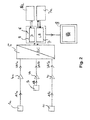
Figur 1- zeigt die Kraftaufnahmeeinheit bzw. die Messeinheit einer erfindungsgemäßen Kraftauswertevorrichtung.
Figur 2- zeigt ein Blockschaltbild der Auswerteeinheit der Kraftauswertevorrichtung gemäß
Figur 1. - Figur 3
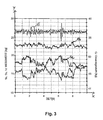
- zeigt die über ein Zeitintervall erfassen Ausgangssignale der Kraftaufnehmer der
Ausgestaltungsform von Figur 1 sowie deren Summensignal (Gesamtsignal). Figur 4- zeigt das Leistungsspektrum, welches aus dem in
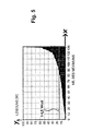
Figur 3 gezeigten Gesamtsignal berechnet wurde. Figur 5- zeigt die nach der Größe sortierten positiv-wertigen lokalen Maxima der zeitlichen Ableitung des Gesamtsignals aus
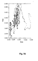
Figur 3 sowie den daraus berechneten Mittelwert. Figur 6- skizziert die Bewegung des dynamischen Schwerpunktes in der Kraftaufnehmerebene während des Zeitintervalls der Messung.
Figur 7- zeigt drei Beispiele für die vom dynamischen Schwerpunkt in der Kraftaufnehmerebene überstrichene Fläche.
- FIG. 1
- shows the power unit or the measuring unit of a force evaluation device according to the invention.
- FIG. 2
- shows a block diagram of the evaluation of the force evaluation device of Figure 1.
- FIG. 3
- shows the over a time interval detect output signals of the force transducer of the embodiment of
FIG. 1 and their sum signal (total signal). - FIG. 4
- shows the range of services, which from the in
FIG. 3 Total signal shown was calculated. - FIG. 5
- shows the sorted by size positive-valued local maxima of the time derivative of the total signal
FIG. 3 as well as the calculated mean value. - FIG. 6
- outlines the movement of the dynamic center of gravity in the force transducer plane during the time interval of the measurement.
- FIG. 7
- shows three examples of the area swept by the dynamic center of gravity at the force transducer level.
Die Aufnehmerachsen der drei Kraftaufnehmer 1a bis 1c sind hier parallel zueinander und in z-Richtung bzw. senkrecht zur Kraftaufnehmerebene (x-y-Ebene) angeordnet. Die Aufnehmerachse eines Kraftaufnehmers ist dadurch definiert, dass eine längs dieser Achse auf dem Kraftaufnehmer 1 einwirkende Kraft oder Kraftkomponente vom Kraftaufnehmer bestimmt bzw. erfasst wird.The transducer axes of the three
Bei den zwischen der Bodenplatte 3 und der Trägerplatte 2 angeordneten Kraftaufnehmern 1a bis 1c handelt es sich um kommerziell erhältliche Kraftmessdosen. Im vorliegenden Fall werden Messdosen verwendet, welche eine maximale Last von 2000 N bzw. 2 kN bei einer Deformation bzw. einem Nennmessweg in Aufnehmerachsrichtung von 0,2 mm aufweisen. Die verwendeten Kraftmessdosen weisen bezüglich der erfassten Kräfte eine Genauigkeitsklasse von < 0,1 % auf. Der Nennkennwert (Sensitivität) bzw. die Signalspannung der drei Messdosen beträgt jeweils 2 mV/V. Im vorliegenden Fall werden die Kraftmessdosen "K-450" der Firma "ATP Messtechnik + Waagen" verwendet.The
In
Der ADC 5 ist ausgangsseitig mit einem Steuercomputer (PC) 6 verbunden. Im vorliegenden Fall handelt es sich bei dem ADC um den Typ "miniLAB 1008" der Firma Measurement Computing Corporation. Im vorliegenden Fall sind die Operationsverstärker 4 sowie der ADC 5 zwischen der Bodenplatte 3 und der Trägerplatte 2 innerhalb des durch die drei Kraftmessdosen 1a bis 1c gebildeten Dreiecks angeordnet (in
Es erfolgt jedoch nicht nur eine Datenübertragung vom ADC 5 zum Computer 6, umgekehrt kann der Steuercomputer 6 auch das Zeitfenster der Öffnung der Messkanäle des ADC 5 über zugehörige Hilfssoftware ansteuern. Somit wird das Messintervall, über das die mittels der Kraftsensoren 1 erfassten Kraftwerte digitalisiert und ausgewertet werden, festgelegt. Der ADC 5 erzeugt somit Messwertzeitreihen der drei Messdosen 1a bis 1c, die zur weiteren Verarbeitung im Computer 6 zur Verfügung stehen. Die Spannungsversorgung des ADC erfolgt hier mit einem Schaltnetzteil, das stabilisiert 12 V abgibt.However, not only is there a data transfer from the
Im vorliegenden Fall sind die Leistungsspektrum-Berechnungseinheit 7 sowie die Differenziereinheit 8 Bestandteile des Computers 6. Beide Einheiten 7, 8 weisen jeweils eine Recheneinheit und einen Speicher samt einer darin gespeicherten Befehlsfolge 7a, 8a auf. Der Speicher und die Recheneinheit der Leistungsspektrum-Berechnungseinheit 7 (in der Figur auch mit LB bezeichnet) und der Differenziereinheit 8 (in der Figur auch mit D bezeichnet) sind hier identisch. Alternativ können jedoch auch für beide Einheiten getrennte Speicher und/oder Recheneinheiten verwendet werden.In the present case, the power
Die drei mittels der drei Kraftmessdosen 1, drei Operationsverstärker 4 und des ADC 5 erfassten und digitalisierten Messwert-Zeitreihen über das Messintervall (also die Messkurven über eine einstellbare Zeitspanne bzw. ein einstellbares Zeitintervall) werden im Computer 6 addiert (siehe
Die Ergebnisse der Berechnung können graphisch von dem Computer 6 auf der Ausgabeeinheit 9 (beispielsweise einem Bildschirm) dargestellt werden. Die beschriebenen Programme bzw. Befehlsfolgen können darüberhinaus auch die kalibrierten Sollwerte der Sensoren 1 überprüfen. Mit den beschriebenen Programmen können darüberhinaus auch die Verstärkungsfaktoren der Vorverstärker, die Abtast- bzw. Samplingraten des ADC 5 und die Messdauer bzw. das Zeitintervall der Datenerfassung angepasst werden. Im vorliegenden Fall beträgt die Samplingrate 100 Hz (generell: mindestens 50 Hz), die Verstärkungsfaktoren wie bereits beschrieben 150 oder 300 und die Messdauer 10 s. Es können jedoch auch andere Werte verwendet werden.The results of the calculation may be graphically displayed by the
Wie
Die in
So zeigt
Zur Berechnung des Leistungsspektrums wurde die Zeitreihe G der Kräftesumme der drei Sensoren 1a bis 1c einer Frequenzzerlegung unterzogen. Dies wurde im vorliegenden Fall mittels der Methode der Fourier-Transformation, hier insbesondere der Fast-Fourier-Transformation FFT durchgeführt. Alternativ zum FFT-Verfahren kann jedoch auch eine Frequenzzerlegung mit der Methode der maximalen Entropie mittels der Leistungsspektrum-Berechnungseinheit 7 durchgeführt werden (zur Methode der maximalen Entropie sowie der Fast-Fourier-Transformation siehe beispielsweise "
Die Methode der maximalen Entropie bietet hierbei den Vorteil einer höheren Auflösung.The method of maximum entropy offers the advantage of a higher resolution.
Die Leistungsspektrum-Berechnungseinheit 7 führt mittels des Programmcodes 7a somit eine Analyse der Frequenzanteile in den Kraftimpulsen (Spektralanalyse) durch. Das ermittelte Leistungsspektrum bzw. Powerspektrum ist in
Das Leistungsspektrum wird dann mittels der Einheit 7 weiter ausgewertet. Es werden arithmetische oder geometrische Mittelwerte der auftretenden Frequenzen bzw. Durchschnittsfrequenzen bestimmt. Diese erlauben eine Aussage über die Reaktionsfähigkeit der Testperson: Je höher die Durchschnitts-frequenzen sind, desto höher ist die Reaktionsfähigkeit der Person.The power spectrum is then further evaluated by means of the
Die beschriebenen Impulsspitzenwerte sind nun ein Maß für die zum entsprechenden Zeitpunkt auftretende Spitzenleistung, welche von der auf der Trägerplatte 2 stehenden Person zur Haltung des Gleichgewichts ausgeübt wird. Dies ergibt sich aus der folgenden Betrachtungsweise: Die Differenzierung einer Kraft nach der Zeit ergibt die Muskelleistung, wenn die geleistete Arbeit (Arbeit = Kraft * Weg) bekannt ist. Die Leistung ist physikalisch definiert als die pro Zeiteinheit geleistete Arbeit. Die Arbeit ergibt sich jedoch im vorliegenden Fall aus der Kraft gegen den "Federweg" der Kraftaufnehmer 1. Somit kann die Differenziereinheit 8 bzw. das Programm 8a auf die beschriebene Art und Weise die lokalen maximalen Impulsspitzenleistungen der einzelnen positiven Kräfteanstiege herausfiltern. Aus diesen Impulsspitzenleistungswerten, deren Spektrum, wie in
Die notwendige Leistung, die erforderlich ist, um einen Körper in die neutrale Schwerpunktlage bzw. in die Gleichgewichtslage zurückzubringen, ist natürlich auch abhängig von der Körpermasse. Somit wird als weitere Kenngröße das Verhältnis aus dem genannten mittleren Impulsspitzenleistungswert und dem zeitlichen Mittel der Summenkurve G über das Messintervall berechnet. Das genannte Verhältnis bzw. die Division des mittleren Impulsspitzenleistungswertes durch die Körpermasse ergibt somit die mittlere Impulsspitzenleistung pro Körpermasse (spezifische mittlere Impulsspitzenleistung). Dieser Wert ist dann unabhängig von der Körpermasse des jeweils untersuchten Individuums vergleichbar.The necessary power required to bring a body back to its neutral center of gravity or its equilibrium position naturally also depends on the body mass. Thus, the ratio of the mean pulse peak power value and the time average of the cumulative curve G over the measurement interval is calculated as a further parameter. The said ratio or division of the mean peak pulse power value by the body mass thus gives the average pulse peak power per body mass (specific mean pulse peak power). This value is then comparable regardless of the body mass of the individual examined.
Die mittlere Impulsspitzenleistung (horizontale Linie) bzw. die hieraus berechnete spezifische mittlere Impulsspitzenleistung (mittlere Impulsspitzenleistung pro Körpermasse) ist ein Maß für den Kraftaufwand und/oder den Leistungsaufwand, den eine auf der Trägerplatte 2 stehende Person zum Halten des Gleichgewichts aufwenden muss.The mean peak pulse power (horizontal line) or the specific mean pulse peak power (mean pulse peak power per body mass) calculated therefrom is a measure of the effort and / or the effort that a person standing on the
Die Berechnung einer weiteren Kenngröße ist in 
Es wird somit der zeitliche Verlauf der Ortsveränderung des dynamischen Schwerpunktes in der Plattformebene bzw. Kraftaufnehmerebene K berechnet, welche aus der Wanderung des Massenschwerpunktes und den zeitlich veränderlichen Beschleunigungskräften der Muskulatur zur Aufrechterhaltung und Korrektur des Gleichgewichts resultiert. Diese Ortsveränderung (x(t), y(t)) (t = Zeit) wird somit für alle Abtast- bzw. Messzeitpunkte im Messintervall bestimmt und vom Computer 6 gespeichert. Als dritte Komponente (z(t)-Komponente) wird die regulative Beschleunigungskraft, welche sich durch Subtraktion des statischen Körpergewichtes von dem momentanen, durch die Messkraftdosen registrierten Gesamtimpuls bzw. der Summe der Einzelimpulse ergibt, in Echtzeit errechnet und gespeichert. Das statische Körpergewicht wird hierbei erst nach Abschluss der Messung berechnet (ebenso wie die Summenkurve G aus den drei Signalen bzw. den drei einzelnen Messwert-Zeitreihen), wenn der allokierte Pufferspeicher im PC ausgelesen ist.It is thus the time course of the change in location of the dynamic center of gravity in the platform level or force transducer level K calculated, which results from the migration of the center of gravity and the temporally variable acceleration forces of the muscles to maintain and correct the balance. This change in location (x (t), y (t)) (t = time) is thus determined for all sampling or measuring times in the measuring interval and stored by the
Claims (11)
- Force evaluating device with which forces acting on force transducers can be determined and evaluated in a time-resolved manner, having
precisely three force transducers (1), which are arranged in the shape of a triangle in a force transducer plane, each having a signal output,
a rigid support plate (2), which can be walked upon and which is coupled to the force transducers (1), wherein the force transducers (1) are arranged on one side of the support plate (2) bordering it, wherein the forces of the force transducers (1) resulting from a compressive force on the force transducers (1), which acts on the support plate (2), can be determined in a time-resolved manner and wherein the output signals of the force transducers (1) can each be scanned with a sampling rate of above 50 Hz and below 250 Hz, and
an evaluating unit (4, 5, 6, 7), with which the force transducers (1) are connected on the signal output side and which has a power spectrum calculation unit (7), with which the power spectrum of an overall signal, formed from the sum of the output signals of the precisely three force transducers (1), can be calculated,
wherein the current location, projected onto the force transducer plane, of the dynamic focus of a person pressure-loading the support plates on the side facing away from the force transducers, and the surface covered by this location or its movement path in the force transducer plane over a time period, can be determined with the evaluating unit (4, 5, 6, 7) from the output signals of the force transducer (1), and
wherein the calculated power spectrum can be evaluated with the evaluating unit (4, 5, 6, 7) in terms of the frequencies which said power spectrum contains by calculating the arithmetical and/or geometrical average of the contained frequencies. - Force evaluating device according to the preceding claim,
characterised by,
a base plate (3) arranged on the side facing away from the support plate (2) bordering the force transducer (1). - Force evaluating device according to one of the preceding claims,
characterised in that,
at least one of the force transducers (1) is a piezo sensor. - Force evaluating method with which forces acting on force transducers are determined and evaluated in a time-resolved manner,
wherein precisely three force transducers (1), each having a signal output, are arranged in the shape of a triangle in a force transducer plane and on one side of a rigid support plate (2), which can be walked upon, and bordering it, and are coupled to the support plate (2) in such a way that the forces of the force transducers (1) resulting from a compressive force on the force transducers (1), which acts on the support plate (2), can be determined in a time-resolved manner,
wherein the support plate (2) on the side facing away from the force transducers (1) is pressure-loaded over a time period by a person walking on the support plate and/or standing on the support plate,
wherein the output signals of the force transducers (1) can each be scanned with a sampling rate of above 50 Hz and below 250 Hz,
wherein, for the time period, a time-resolved overall signal is formed from the sum of the output signals of the precisely three force transducers (1), resulting from the pressure-loading on the force transducers (1),
wherein the power spectrum of the overall signal is calculated and evaluated in terms of the frequencies it contains, by calculating the arithmetical and/or geometrical average of the contained frequencies, and
wherein, over the time period, the current location of the dynamic focus of the person, which is
projected onto the force transducer plane, and the surface covered by this location or its movement path in the force transducer plane over the time period are determined from the output signals of the force transducers (1). - Force evaluating method according to the preceding claim,
characterised in that,
the time average of the overall signal over the time period is formed for determining the average pressure-loading of the support plate. - Force evaluating method according to one of the two preceding claims,
characterised in that,
the dynamic focus is composed of a static portion resulting from the mass of the person, and of a portion resulting from the force executed by the person on the support plate by means of muscle forces. - Force evaluating method according to one of the three preceding claims,
characterised in that,
the current location of the dynamic focus is calculated according to
- Force evaluating method according to one of the four preceding claims,
characterised in that,
the ratio of the determined covered surface for a first person and the determined covered surface for a second person, who is not identical to the first person, is calculated. - Force evaluation method according to one of the five preceding claims,
characterised in that,
the power spectrum of the overall signal is calculated by means of the Fourier transform or by means of the method of maximum entropy. - Force evaluating method according to one of the six preceding claims,
characterised in that,
the calculated power spectrum is evaluated in terms of the frequencies which it contains by calculating maxima in the power spectrum. - Use of a force evaluating device or a force evaluating method according to one of the preceding claims for determining or monitoring the roadworthiness of people, for determining the influence of alcohol or drugs on the motor abilities of people or for determining performance characteristics for the physical fitness of people.
Applications Claiming Priority (2)
| Application Number | Priority Date | Filing Date | Title |
|---|---|---|---|
| DE102004032398 | 2004-07-03 | ||
| PCT/DE2005/000467 WO2006005279A1 (en) | 2004-07-03 | 2005-03-15 | Force evaluating device and force evaluating method for determining balance characteristics |
Publications (2)
| Publication Number | Publication Date |
|---|---|
| EP1763656A1 EP1763656A1 (en) | 2007-03-21 |
| EP1763656B1 true EP1763656B1 (en) | 2013-09-25 |
Family
ID=34965469
Family Applications (1)
| Application Number | Title | Priority Date | Filing Date |
|---|---|---|---|
| EP05733545.7A Active EP1763656B1 (en) | 2004-07-03 | 2005-03-15 | Force evaluating device and force evaluating method for determining balance characteristics |
Country Status (6)
| Country | Link |
|---|---|
| US (1) | US20080188775A1 (en) |
| EP (1) | EP1763656B1 (en) |
| JP (1) | JP2008504080A (en) |
| CN (1) | CN1985155A (en) |
| DE (1) | DE112005002192A5 (en) |
| WO (1) | WO2006005279A1 (en) |
Families Citing this family (23)
| Publication number | Priority date | Publication date | Assignee | Title |
|---|---|---|---|---|
| JP4749897B2 (en) * | 2006-03-15 | 2011-08-17 | ニッタ株式会社 | Walking training support device |
| DE102006032081B4 (en) * | 2006-07-11 | 2013-09-26 | Julius-Maximilians-Universität Würzburg | Ergometer, running shoe and bicycle pedal |
| JP4805070B2 (en) * | 2006-09-07 | 2011-11-02 | ニッタ株式会社 | Fall risk assessment device |
| US8152744B2 (en) * | 2008-03-25 | 2012-04-10 | Comfort Lab. Inc. | Shoe or insole fitting navigation system |
| BRPI0913494A2 (en) * | 2008-09-12 | 2016-07-26 | Koninkl Philips Electronics Nv | fall detection system and method of operation of a fall detection system |
| EP2421437A1 (en) * | 2009-04-24 | 2012-02-29 | Commissariat à l'Énergie Atomique et aux Énergies Alternatives | System and method for determining the activity of a mobile element |
| JP5426964B2 (en) * | 2009-08-26 | 2014-02-26 | パナソニック株式会社 | Health measuring device |
| CN101975607B (en) * | 2010-11-15 | 2013-09-04 | 黑龙江省水利科学研究院 | Electronic weigher |
| DE102012101049B4 (en) * | 2012-02-09 | 2015-06-18 | T & T Medilogic Medizintechnik Gmbh | Device for foot diagnostics |
| DE102012101054A1 (en) * | 2012-02-09 | 2013-08-14 | T & T Medilogic Medizintechnik Gmbh | Device for foot diagnostics, particularly for producing orthopedic aids, has pressure measurement plate attached on glass plate for simultaneous detection of plantar image and pressure distribution on foot underside of person to be examined |
| JP6183827B2 (en) * | 2013-03-14 | 2017-08-23 | 株式会社タニタ | Motor function evaluation apparatus and motor function evaluation method |
| CN106137132B (en) * | 2013-03-14 | 2019-05-07 | 株式会社百利达 | Motion function evaluating apparatus and method, arithmetic unit and method |
| CN103251411A (en) * | 2013-04-08 | 2013-08-21 | 杭州电子科技大学 | Complexity based pressure center nonlinear feature extraction method |
| US20150099245A1 (en) * | 2013-10-01 | 2015-04-09 | Universite Du Quebec A Chicoutimi | Method for monitoring an activity of a cognitively impaired user and device therefore |
| US10307084B2 (en) | 2015-06-30 | 2019-06-04 | Zibrio Inc. | Identifying fall risk using machine learning algorithms |
| CN105286874B (en) * | 2015-11-03 | 2018-06-19 | 长安大学 | A kind of system and method for being used to predict Falls in Old People risk |
| CN105708465B (en) * | 2016-04-19 | 2019-12-13 | 东华大学 | household scale capable of detecting spine state and using method thereof |
| CN107643132A (en) * | 2016-07-22 | 2018-01-30 | 上海域丰传感仪器有限公司 | One kind sealing pressure ceramic flat membrane pressure sensor |
| SG11201902960QA (en) * | 2016-10-07 | 2019-05-30 | Panasonic Ip Man Co Ltd | Cognitive function evaluation device, cognitive function evaluation method, and program |
| CN107967931B (en) * | 2017-12-29 | 2024-01-26 | 新绎健康科技有限公司 | Body balance data collector |
| CN108309236B (en) * | 2018-01-15 | 2021-08-27 | 新绎健康科技有限公司 | Human body balance evaluation method and system |
| CN111977233A (en) * | 2019-05-22 | 2020-11-24 | 深圳市瑞微智能有限责任公司 | Method, device and system for positioning material in and out of warehouse |
| CN111776247A (en) * | 2020-06-04 | 2020-10-16 | 核工业北京地质研究院 | System and method for measuring thrust of launching system of gliding unmanned aerial vehicle |
Citations (1)
| Publication number | Priority date | Publication date | Assignee | Title |
|---|---|---|---|---|
| DE10151361A1 (en) * | 2001-10-22 | 2003-04-30 | Novotec Medical Gmbh | Device for evaluating the motor movements of a human, comprises a platform, such as a set of steps, that is mounted on four support points which incorporate force sensors that are linked to evaluation electronics |
Family Cites Families (36)
| Publication number | Priority date | Publication date | Assignee | Title |
|---|---|---|---|---|
| US3169022A (en) * | 1962-04-10 | 1965-02-09 | Elwood A Kretsinger | Means for indicating the distribution of a golfer's weight at the instant of ball impact |
| US3712294A (en) * | 1970-07-24 | 1973-01-23 | J Muller | Method and apparatus for measuring human reaction |
| US3894437A (en) * | 1974-01-10 | 1975-07-15 | John L Hagy | Method of and means for dynamic gait analysis |
| US4195643A (en) * | 1976-12-27 | 1980-04-01 | Massachusetts Institute Of Technology | Diagnostic force analysis system |
| US4267728A (en) * | 1978-07-04 | 1981-05-19 | Manley Michael T | Apparatus for analyzing the forces acting on a human foot |
| US4394865A (en) * | 1980-05-22 | 1983-07-26 | Belorussky Nauchnoissledovatelsky Institut Kardiologii | Apparatus for determining levels of physical loads |
| US4830024A (en) * | 1982-08-16 | 1989-05-16 | Nashner Lewis M | Apparatus and method for determining the presence of vestibular perilymph fistulae and other abnormal coupling between the air-filled middle ear and the fluid-filled inner ear |
| US4631676A (en) * | 1983-05-25 | 1986-12-23 | Hospital For Joint Diseases Or | Computerized video gait and motion analysis system and method |
| US4600016A (en) * | 1985-08-26 | 1986-07-15 | Biomechanical Engineering Corporation | Method and apparatus for gait recording and analysis |
| US5476103A (en) * | 1991-10-10 | 1995-12-19 | Neurocom International, Inc. | Apparatus and method for assessment and biofeedback training of leg coordination and strength skills |
| WO1993006779A1 (en) * | 1991-10-10 | 1993-04-15 | Neurocom International, Inc. | Apparatus and method for characterizing gait |
| FR2690613B3 (en) | 1992-04-29 | 1994-07-13 | Kohen Raz Reuven | TETRA-ATAXIAMETRIC POSTUROGRAPHY METHOD, SYSTEM FOR IMPLEMENTING SAME AND ASSOCIATED MULTI-SENSOR DEVICE. |
| FI94589C (en) * | 1992-09-15 | 1995-10-10 | Increa Oy | Method and apparatus for measuring physical fitness |
| US5388591A (en) * | 1992-12-09 | 1995-02-14 | Trustees Of Boston University | Method and apparatus for analyzing the human postural control system |
| US6067986A (en) * | 1993-10-29 | 2000-05-30 | Kluger; Alan | Method and apparatus employing motor measures for early diagnosis and staging of dementia |
| US5885229A (en) * | 1995-07-19 | 1999-03-23 | Nippon Telegraph & Telephone Corp. | Walking pattern processing method and system for embodying the same |
| JPH09120464A (en) * | 1995-08-21 | 1997-05-06 | Matsushita Electric Ind Co Ltd | Rehabilitation support device |
| US6231527B1 (en) * | 1995-09-29 | 2001-05-15 | Nicholas Sol | Method and apparatus for biomechanical correction of gait and posture |
| US5830158A (en) * | 1996-07-22 | 1998-11-03 | Zanakis; Michael | Dynamic system for determining human physical instability |
| US5919150A (en) * | 1996-07-22 | 1999-07-06 | Zanakis; Michael F. | Dynamic system for determining human physical instability |
| EP0969901A1 (en) * | 1997-03-12 | 2000-01-12 | Neurocom International, Inc | System and method for monitoring training programs |
| US6063046A (en) * | 1997-04-11 | 2000-05-16 | Allum; John H. | Method and apparatus for the diagnosis and rehabilitation of balance disorders |
| JP2961706B2 (en) * | 1997-04-28 | 1999-10-12 | アニマ株式会社 | Severity diagnostic device for disease |
| US6162189A (en) * | 1999-05-26 | 2000-12-19 | Rutgers, The State University Of New Jersey | Ankle rehabilitation system |
| US6245014B1 (en) * | 1999-11-18 | 2001-06-12 | Atlantic Limited Partnership | Fitness for duty testing device and method |
| FR2803507B1 (en) * | 2000-01-10 | 2003-05-30 | Eric Berthonnaud | DEVICE FOR EVALUATING THE BALANCE POSITION OF THE HUMAN BODY |
| FR2803738B1 (en) * | 2000-01-19 | 2002-03-29 | Isabelle Joseph Rougier | METHOD FOR ANALYZING THE STATOKINESIMETRIC SIGNAL FROM A FORCE PLATFORM |
| US6699207B2 (en) * | 2000-05-30 | 2004-03-02 | University Of Maryland | Method and apparatus for detecting lameness in animals |
| FR2810556B1 (en) * | 2000-06-23 | 2002-09-13 | Patrick Savet Sarl | DEVICE FOR ANALYZING DISORDERS IN THE BALANCE AND POSTURE OF AN INDIVIDUAL |
| US6561991B2 (en) * | 2000-12-19 | 2003-05-13 | The Research Foundation Of The State University Of New York (Suny) | Non-invasive method and system of quantifying human postural stability |
| FR2834197B1 (en) * | 2001-12-28 | 2004-02-27 | Optimage | METHOD AND DEVICE FOR EVALUATING SKELETON BALANCING FORCES |
| US6936016B2 (en) * | 2002-05-17 | 2005-08-30 | Bertec Corporation | Method for analysis of abnormal body tremors |
| AUPS325602A0 (en) * | 2002-06-28 | 2002-07-18 | Vardy, Terence | Exercise apparatus |
| CN2623167Y (en) * | 2002-11-14 | 2004-07-07 | 精量电子(深圳)有限公司 | Fat balance with transparent electrode for human body |
| US20050015002A1 (en) * | 2003-07-18 | 2005-01-20 | Dixon Gary S. | Integrated protocol for diagnosis, treatment, and prevention of bone mass degradation |
| US20060293613A1 (en) * | 2005-06-27 | 2006-12-28 | Concept Development Group | Method and Apparatus for Automated Monitoring and Tracking of the Trajectory of Patients' Center of Gravity Movements |
-
2005
- 2005-03-15 DE DE112005002192T patent/DE112005002192A5/en not_active Withdrawn
- 2005-03-15 WO PCT/DE2005/000467 patent/WO2006005279A1/en active Application Filing
- 2005-03-15 US US11/630,942 patent/US20080188775A1/en not_active Abandoned
- 2005-03-15 EP EP05733545.7A patent/EP1763656B1/en active Active
- 2005-03-15 CN CNA2005800226666A patent/CN1985155A/en active Pending
- 2005-03-15 JP JP2007518440A patent/JP2008504080A/en active Pending
Patent Citations (1)
| Publication number | Priority date | Publication date | Assignee | Title |
|---|---|---|---|---|
| DE10151361A1 (en) * | 2001-10-22 | 2003-04-30 | Novotec Medical Gmbh | Device for evaluating the motor movements of a human, comprises a platform, such as a set of steps, that is mounted on four support points which incorporate force sensors that are linked to evaluation electronics |
Non-Patent Citations (5)
| Title |
|---|
| BARATTO L, MORASSO PG, RE C, SPADA G.: "A new look at posturographic analysis in the clinical context: sway-density versus other parameterization techniques.", MOTOR CONTROL., vol. 6, 2002, pages 246 - 270 * |
| BURDETT RG, SKRINAR GS, SIMON SR.: "Comparison of mechanical work and metabolic energy consumption during normal gait.", J ORTHOP RES., vol. 1, no. 1, 1983, New York, pages 63 - 72 * |
| HASAN S S ET AL: "DRUGS AND POSTURAL SWAY", IEEE ENGINEERING IN MEDICINE AND BIOLOGY MAGAZINE, IEEE SERVICE CENTER, PISACATAWAY, NJ, US LNKD- DOI:10.1109/51.256956, vol. 11, no. 4, 1 December 1992 (1992-12-01), pages 35 - 41, XP000334873, ISSN: 0739-5175 * |
| OLIVEIRA L F ET AL: "Calculation of area of stabilometric signals using principal component analysis", PHYSIOLOGICAL MEASUREMENT, INSTITUTE OF PHYSICS PUBLISHING, BRISTOL, GB LNKD- DOI:10.1088/0967-3334/17/4/008, vol. 17, no. 4, 1 November 1996 (1996-11-01), pages 305 - 312, XP020073758, ISSN: 0967-3334 * |
| SUTHERLAND D H: "The evolution of clinical gait analysis part III - kinetics and energy assessment", GAIT & POSTURE, ELSEVIER LNKD- DOI:10.1016/J.GAITPOST.2004.07.008, vol. 21, no. 4, 1 June 2005 (2005-06-01), pages 447 - 461, XP004887349, ISSN: 0966-6362 * |
Also Published As
| Publication number | Publication date |
|---|---|
| WO2006005279A1 (en) | 2006-01-19 |
| CN1985155A (en) | 2007-06-20 |
| DE112005002192A5 (en) | 2007-07-12 |
| EP1763656A1 (en) | 2007-03-21 |
| US20080188775A1 (en) | 2008-08-07 |
| JP2008504080A (en) | 2008-02-14 |
Similar Documents
| Publication | Publication Date | Title |
|---|---|---|
| EP1763656B1 (en) | Force evaluating device and force evaluating method for determining balance characteristics | |
| EP0538739B1 (en) | Method and device for determining the state of health of a living being | |
| DE60304539T2 (en) | Apparatus and method for measuring local skin impedance with a multiple electrode array | |
| Darling et al. | Variability of motor potentials evoked by transcranial magnetic stimulation depends on muscle activation | |
| DE60116344T2 (en) | BODY MOTOR MONITORING SYSTEM AND METHOD | |
| DE112014004760T5 (en) | Vitalsignal measuring apparatus and method for estimating a contact condition | |
| DE10211765B4 (en) | Device for localizing the target point of electrodes for brain stimulation, in particular for deep brain stimulation | |
| DE10119527A1 (en) | Method for the mobile or stationary acquisition of body function and metabolic data of a living body and device for carrying out the method | |
| DE102008021940A1 (en) | Stimulation arrangement for measuring the physiological signal reactivity | |
| EP1175865B1 (en) | Cardiological implantable apparatus comprising an evaluation method for determining the temporal stationarity of measured cardiological signals | |
| AT411011B (en) | Device for quantifying motion malfunctions in Parkinson's disease | |
| EP1487332B1 (en) | Measuring device for reducing measuring errors | |
| WO2014118022A1 (en) | Device for measuring pain and/or for pain detection | |
| WO2020208264A1 (en) | Combination measuring instrument for recording neuromuscular functions | |
| DE102006032081B4 (en) | Ergometer, running shoe and bicycle pedal | |
| DE102018009740A1 (en) | Foot force measuring device pedomotograph | |
| DE102021113372B3 (en) | Analysis method, analysis device and executable computer program for the medical-technical analysis of a heart rate curve measured on a body | |
| DE3330130A1 (en) | Apparatus for stimulating current therapy and/or diagnosis | |
| DE102009034002B4 (en) | Finger force-measuring device | |
| DE2704403C2 (en) | Device for measuring the reflex time | |
| DE60203877T2 (en) | APPARATUS FOR DIAGNOSIS AND MONITORING OF THE CONDITION OF THE VEGETATIVE NERVOUS SYSTEM AND FOR THE TREATMENT OF ILLNESSES AND SUFFERING FROM HORMONE DISORDER | |
| EP0972489A2 (en) | System and method for obtaining information on a patient having Parkinson's disease | |
| DE102004020515A1 (en) | Wireless recording, remote monitoring of animal muscle activities involves using measurement device miniaturized/ergonomically designed so investigated animal is almost unaffected in perception, movement processes and natural environment | |
| Riedmann | Analysis, design and prototypical implementation of a serious game for balance rehabilitation providing personalized level generation based on machine learning techniques | |
| DE102021205521A1 (en) | Device and method for determining blood pressure when weighing a person |
Legal Events
| Date | Code | Title | Description |
|---|---|---|---|
| PUAI | Public reference made under article 153(3) epc to a published international application that has entered the european phase |
Free format text: ORIGINAL CODE: 0009012 |
|
| 17P | Request for examination filed |
Effective date: 20061222 |
|
| AK | Designated contracting states |
Kind code of ref document: A1 Designated state(s): AT BE BG CH CY CZ DE DK EE ES FI FR GB GR HU IE IS IT LI LT LU MC NL PL PT RO SE SI SK TR |
|
| AX | Request for extension of the european patent |
Extension state: AL BA HR LV MK YU |
|
| 17Q | First examination report despatched |
Effective date: 20080414 |
|
| TPAC | Observations filed by third parties |
Free format text: ORIGINAL CODE: EPIDOSNTIPA |
|
| GRAP | Despatch of communication of intention to grant a patent |
Free format text: ORIGINAL CODE: EPIDOSNIGR1 |
|
| INTG | Intention to grant announced |
Effective date: 20130703 |
|
| GRAS | Grant fee paid |
Free format text: ORIGINAL CODE: EPIDOSNIGR3 |
|
| GRAA | (expected) grant |
Free format text: ORIGINAL CODE: 0009210 |
|
| AK | Designated contracting states |
Kind code of ref document: B1 Designated state(s): AT BE BG CH CY CZ DE DK EE ES FI FR GB GR HU IE IS IT LI LT LU MC NL PL PT RO SE SI SK TR |
|
| AX | Request for extension of the european patent |
Extension state: AL BA HR LV MK YU |
|
| REG | Reference to a national code |
Ref country code: GB Ref legal event code: FG4D Free format text: NOT ENGLISH |
|
| REG | Reference to a national code |
Ref country code: CH Ref legal event code: EP |
|
| REG | Reference to a national code |
Ref country code: AT Ref legal event code: REF Ref document number: 633889 Country of ref document: AT Kind code of ref document: T Effective date: 20131015 |
|
| REG | Reference to a national code |
Ref country code: IE Ref legal event code: FG4D Free format text: LANGUAGE OF EP DOCUMENT: GERMAN |
|
| REG | Reference to a national code |
Ref country code: DE Ref legal event code: R096 Ref document number: 502005013991 Country of ref document: DE Effective date: 20131114 |
|
| REG | Reference to a national code |
Ref country code: DE Ref legal event code: R082 Ref document number: 502005013991 Country of ref document: DE Representative=s name: PFENNING MEINIG & PARTNER GBR, DE Ref country code: DE Ref legal event code: R082 Ref document number: 502005013991 Country of ref document: DE Representative=s name: PFENNING, MEINIG & PARTNER MBB PATENTANWAELTE, DE |
|
| PG25 | Lapsed in a contracting state [announced via postgrant information from national office to epo] |
Ref country code: LT Free format text: LAPSE BECAUSE OF FAILURE TO SUBMIT A TRANSLATION OF THE DESCRIPTION OR TO PAY THE FEE WITHIN THE PRESCRIBED TIME-LIMIT Effective date: 20130925 Ref country code: SE Free format text: LAPSE BECAUSE OF FAILURE TO SUBMIT A TRANSLATION OF THE DESCRIPTION OR TO PAY THE FEE WITHIN THE PRESCRIBED TIME-LIMIT Effective date: 20130925 |
|
| REG | Reference to a national code |
Ref country code: NL Ref legal event code: VDEP Effective date: 20130925 |
|
| REG | Reference to a national code |
Ref country code: LT Ref legal event code: MG4D |
|
| PG25 | Lapsed in a contracting state [announced via postgrant information from national office to epo] |
Ref country code: SI Free format text: LAPSE BECAUSE OF FAILURE TO SUBMIT A TRANSLATION OF THE DESCRIPTION OR TO PAY THE FEE WITHIN THE PRESCRIBED TIME-LIMIT Effective date: 20130925 Ref country code: FI Free format text: LAPSE BECAUSE OF FAILURE TO SUBMIT A TRANSLATION OF THE DESCRIPTION OR TO PAY THE FEE WITHIN THE PRESCRIBED TIME-LIMIT Effective date: 20130925 Ref country code: GR Free format text: LAPSE BECAUSE OF FAILURE TO SUBMIT A TRANSLATION OF THE DESCRIPTION OR TO PAY THE FEE WITHIN THE PRESCRIBED TIME-LIMIT Effective date: 20131226 |
|
| PG25 | Lapsed in a contracting state [announced via postgrant information from national office to epo] |
Ref country code: RO Free format text: LAPSE BECAUSE OF FAILURE TO SUBMIT A TRANSLATION OF THE DESCRIPTION OR TO PAY THE FEE WITHIN THE PRESCRIBED TIME-LIMIT Effective date: 20130925 Ref country code: EE Free format text: LAPSE BECAUSE OF FAILURE TO SUBMIT A TRANSLATION OF THE DESCRIPTION OR TO PAY THE FEE WITHIN THE PRESCRIBED TIME-LIMIT Effective date: 20130925 Ref country code: CZ Free format text: LAPSE BECAUSE OF FAILURE TO SUBMIT A TRANSLATION OF THE DESCRIPTION OR TO PAY THE FEE WITHIN THE PRESCRIBED TIME-LIMIT Effective date: 20130925 Ref country code: IS Free format text: LAPSE BECAUSE OF FAILURE TO SUBMIT A TRANSLATION OF THE DESCRIPTION OR TO PAY THE FEE WITHIN THE PRESCRIBED TIME-LIMIT Effective date: 20140125 Ref country code: SK Free format text: LAPSE BECAUSE OF FAILURE TO SUBMIT A TRANSLATION OF THE DESCRIPTION OR TO PAY THE FEE WITHIN THE PRESCRIBED TIME-LIMIT Effective date: 20130925 Ref country code: NL Free format text: LAPSE BECAUSE OF FAILURE TO SUBMIT A TRANSLATION OF THE DESCRIPTION OR TO PAY THE FEE WITHIN THE PRESCRIBED TIME-LIMIT Effective date: 20130925 |
|
| PG25 | Lapsed in a contracting state [announced via postgrant information from national office to epo] |
Ref country code: ES Free format text: LAPSE BECAUSE OF FAILURE TO SUBMIT A TRANSLATION OF THE DESCRIPTION OR TO PAY THE FEE WITHIN THE PRESCRIBED TIME-LIMIT Effective date: 20130925 Ref country code: CY Free format text: LAPSE BECAUSE OF FAILURE TO SUBMIT A TRANSLATION OF THE DESCRIPTION OR TO PAY THE FEE WITHIN THE PRESCRIBED TIME-LIMIT Effective date: 20130925 Ref country code: PL Free format text: LAPSE BECAUSE OF FAILURE TO SUBMIT A TRANSLATION OF THE DESCRIPTION OR TO PAY THE FEE WITHIN THE PRESCRIBED TIME-LIMIT Effective date: 20130925 |
|
| REG | Reference to a national code |
Ref country code: DE Ref legal event code: R097 Ref document number: 502005013991 Country of ref document: DE |
|
| PG25 | Lapsed in a contracting state [announced via postgrant information from national office to epo] |
Ref country code: PT Free format text: LAPSE BECAUSE OF FAILURE TO SUBMIT A TRANSLATION OF THE DESCRIPTION OR TO PAY THE FEE WITHIN THE PRESCRIBED TIME-LIMIT Effective date: 20140127 |
|
| PLBE | No opposition filed within time limit |
Free format text: ORIGINAL CODE: 0009261 |
|
| STAA | Information on the status of an ep patent application or granted ep patent |
Free format text: STATUS: NO OPPOSITION FILED WITHIN TIME LIMIT |
|
| PG25 | Lapsed in a contracting state [announced via postgrant information from national office to epo] |
Ref country code: IT Free format text: LAPSE BECAUSE OF FAILURE TO SUBMIT A TRANSLATION OF THE DESCRIPTION OR TO PAY THE FEE WITHIN THE PRESCRIBED TIME-LIMIT Effective date: 20130925 |
|
| 26N | No opposition filed |
Effective date: 20140626 |
|
| PG25 | Lapsed in a contracting state [announced via postgrant information from national office to epo] |
Ref country code: DK Free format text: LAPSE BECAUSE OF FAILURE TO SUBMIT A TRANSLATION OF THE DESCRIPTION OR TO PAY THE FEE WITHIN THE PRESCRIBED TIME-LIMIT Effective date: 20130925 |
|
| REG | Reference to a national code |
Ref country code: DE Ref legal event code: R097 Ref document number: 502005013991 Country of ref document: DE Effective date: 20140626 |
|
| PG25 | Lapsed in a contracting state [announced via postgrant information from national office to epo] |
Ref country code: LU Free format text: LAPSE BECAUSE OF FAILURE TO SUBMIT A TRANSLATION OF THE DESCRIPTION OR TO PAY THE FEE WITHIN THE PRESCRIBED TIME-LIMIT Effective date: 20140315 |
|
| REG | Reference to a national code |
Ref country code: CH Ref legal event code: PL |
|
| REG | Reference to a national code |
Ref country code: IE Ref legal event code: MM4A |
|
| PG25 | Lapsed in a contracting state [announced via postgrant information from national office to epo] |
Ref country code: CH Free format text: LAPSE BECAUSE OF NON-PAYMENT OF DUE FEES Effective date: 20140331 Ref country code: LI Free format text: LAPSE BECAUSE OF NON-PAYMENT OF DUE FEES Effective date: 20140331 Ref country code: IE Free format text: LAPSE BECAUSE OF NON-PAYMENT OF DUE FEES Effective date: 20140315 |
|
| REG | Reference to a national code |
Ref country code: AT Ref legal event code: MM01 Ref document number: 633889 Country of ref document: AT Kind code of ref document: T Effective date: 20140315 |
|
| PG25 | Lapsed in a contracting state [announced via postgrant information from national office to epo] |
Ref country code: AT Free format text: LAPSE BECAUSE OF NON-PAYMENT OF DUE FEES Effective date: 20140315 |
|
| REG | Reference to a national code |
Ref country code: FR Ref legal event code: PLFP Year of fee payment: 12 |
|
| PG25 | Lapsed in a contracting state [announced via postgrant information from national office to epo] |
Ref country code: MC Free format text: LAPSE BECAUSE OF FAILURE TO SUBMIT A TRANSLATION OF THE DESCRIPTION OR TO PAY THE FEE WITHIN THE PRESCRIBED TIME-LIMIT Effective date: 20130925 Ref country code: BG Free format text: LAPSE BECAUSE OF FAILURE TO SUBMIT A TRANSLATION OF THE DESCRIPTION OR TO PAY THE FEE WITHIN THE PRESCRIBED TIME-LIMIT Effective date: 20130925 |
|
| PGFP | Annual fee paid to national office [announced via postgrant information from national office to epo] |
Ref country code: FR Payment date: 20160330 Year of fee payment: 12 Ref country code: GB Payment date: 20160330 Year of fee payment: 12 |
|
| PG25 | Lapsed in a contracting state [announced via postgrant information from national office to epo] |
Ref country code: TR Free format text: LAPSE BECAUSE OF FAILURE TO SUBMIT A TRANSLATION OF THE DESCRIPTION OR TO PAY THE FEE WITHIN THE PRESCRIBED TIME-LIMIT Effective date: 20130925 Ref country code: HU Free format text: LAPSE BECAUSE OF FAILURE TO SUBMIT A TRANSLATION OF THE DESCRIPTION OR TO PAY THE FEE WITHIN THE PRESCRIBED TIME-LIMIT; INVALID AB INITIO Effective date: 20050315 Ref country code: BE Free format text: LAPSE BECAUSE OF FAILURE TO SUBMIT A TRANSLATION OF THE DESCRIPTION OR TO PAY THE FEE WITHIN THE PRESCRIBED TIME-LIMIT Effective date: 20140331 |
|
| PGFP | Annual fee paid to national office [announced via postgrant information from national office to epo] |
Ref country code: DE Payment date: 20160330 Year of fee payment: 12 |
|
| REG | Reference to a national code |
Ref country code: DE Ref legal event code: R119 Ref document number: 502005013991 Country of ref document: DE |
|
| GBPC | Gb: european patent ceased through non-payment of renewal fee |
Effective date: 20170315 |
|
| REG | Reference to a national code |
Ref country code: FR Ref legal event code: ST Effective date: 20171130 |
|
| PG25 | Lapsed in a contracting state [announced via postgrant information from national office to epo] |
Ref country code: DE Free format text: LAPSE BECAUSE OF NON-PAYMENT OF DUE FEES Effective date: 20171003 Ref country code: FR Free format text: LAPSE BECAUSE OF NON-PAYMENT OF DUE FEES Effective date: 20170331 |
|
| PG25 | Lapsed in a contracting state [announced via postgrant information from national office to epo] |
Ref country code: GB Free format text: LAPSE BECAUSE OF NON-PAYMENT OF DUE FEES Effective date: 20170315 |