EP1759626A2 - Endoscope - Google Patents
Endoscope Download PDFInfo
- Publication number
- EP1759626A2 EP1759626A2 EP06016066A EP06016066A EP1759626A2 EP 1759626 A2 EP1759626 A2 EP 1759626A2 EP 06016066 A EP06016066 A EP 06016066A EP 06016066 A EP06016066 A EP 06016066A EP 1759626 A2 EP1759626 A2 EP 1759626A2
- Authority
- EP
- European Patent Office
- Prior art keywords
- collet
- endoscope
- endoscope according
- nut
- cone
- Prior art date
- Legal status (The legal status is an assumption and is not a legal conclusion. Google has not performed a legal analysis and makes no representation as to the accuracy of the status listed.)
- Granted
Links
- 238000003780 insertion Methods 0.000 claims description 12
- 230000037431 insertion Effects 0.000 claims description 12
- 238000004026 adhesive bonding Methods 0.000 claims description 3
- 230000004323 axial length Effects 0.000 claims description 3
- 230000002093 peripheral effect Effects 0.000 claims 1
- 238000005286 illumination Methods 0.000 description 4
- 238000011010 flushing procedure Methods 0.000 description 3
- 239000007788 liquid Substances 0.000 description 3
- 238000010276 construction Methods 0.000 description 2
- 230000003287 optical effect Effects 0.000 description 2
- 230000001419 dependent effect Effects 0.000 description 1
- 238000001035 drying Methods 0.000 description 1
- 230000003993 interaction Effects 0.000 description 1
- 230000002262 irrigation Effects 0.000 description 1
- 238000003973 irrigation Methods 0.000 description 1
- 230000013011 mating Effects 0.000 description 1
- 210000000056 organ Anatomy 0.000 description 1
Images


Classifications
-
- A—HUMAN NECESSITIES
- A61—MEDICAL OR VETERINARY SCIENCE; HYGIENE
- A61B—DIAGNOSIS; SURGERY; IDENTIFICATION
- A61B1/00—Instruments for performing medical examinations of the interior of cavities or tubes of the body by visual or photographical inspection, e.g. endoscopes; Illuminating arrangements therefor
- A61B1/00064—Constructional details of the endoscope body
- A61B1/00071—Insertion part of the endoscope body
- A61B1/0008—Insertion part of the endoscope body characterised by distal tip features
- A61B1/00098—Deflecting means for inserted tools
-
- A—HUMAN NECESSITIES
- A61—MEDICAL OR VETERINARY SCIENCE; HYGIENE
- A61B—DIAGNOSIS; SURGERY; IDENTIFICATION
- A61B1/00—Instruments for performing medical examinations of the interior of cavities or tubes of the body by visual or photographical inspection, e.g. endoscopes; Illuminating arrangements therefor
- A61B1/012—Instruments for performing medical examinations of the interior of cavities or tubes of the body by visual or photographical inspection, e.g. endoscopes; Illuminating arrangements therefor characterised by internal passages or accessories therefor
- A61B1/018—Instruments for performing medical examinations of the interior of cavities or tubes of the body by visual or photographical inspection, e.g. endoscopes; Illuminating arrangements therefor characterised by internal passages or accessories therefor for receiving instruments
Definitions
- the invention relates to an endoscope with a shaft in which at least one working channel is arranged and arranged at the distal end of the shaft endoscope head, wherein arranged in the endoscope head part of the working channel via a Bowden cable, which is mounted on the proximal side via a collet on a control handle is, is pivotable relative to the associated working channel.
- This known construction for tensioning the Bowden cable has the disadvantage that the pull rope can be pushed so deep into the collet, that the pull rope is too taut and pivoting of the working channel is hardly possible. To minimize this risk, the working channel and thus the traction cable of the Bowden cable must first be transferred to a predetermined starting position, so that subsequently a sufficient, but not too tight tension of the hawser can be done by means of the collet.
- This known Tensioning is cumbersome on the one hand and on the other hand does not prevent a faulty tension of the pull rope.
- the invention has for its object to design an endoscope of the type mentioned that with a simple structure always a uniform tension of the Bowden cable is guaranteed.
- the solution to this problem is inventively characterized in that the insertion depth of a pull cable of the Bowden cable can be limited in the collet via a force acting on the pull cable and the collet pressure element.
- a cone is formed on the proximal side, which cooperates with a counter-cone, which is formed in a nut which can be screwed onto the collet.
- the pressure element according to the invention acts on at least one spring element on the counter-cone.
- the pressure element is designed as a hat-shaped component, wherein the axial length of the pressure element of the preferred and maximum insertion depth of the pull rope corresponds to the collet. Since the hat-shaped pressure element spring-loaded on the mating cone, which defines the end position of the collet in the mother, there is always the same and predictable tension of the pull rope, because when screwing the nut on coaxially arranged on the pull rope collet, the pull rope proximal only the axial length of the Pressing element can protrude accordingly over the collet. By the pressure element thus the insertion depth of the pull cable is limited during assembly of the Bowden cable on the control handle.
- the spring element is supported distally on a circumferential collar of the hat-shaped pressure element and on the proximal side on a rear wall of the nut designed as a cap nut.
- a closed rear wall of the hat-shaped pressure element is designed to point outwardly tapering.
- the counter-cone is formed on an insertable into the nut sleeve, wherein the sleeve, for example by gluing, is secured against rotation in the nut to prevent rotation of the provided with the counter-cone sleeve when screwing the nut ,
- a thread-free recess is formed on the sleeve distal side. This recess widening the inner diameter of the sleeve allows centering of the collet in the nut.
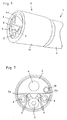
- FIG. 1 shows the distal end of an endoscope 1 with an endoscope head 3 which forms the distal end of an endoscope shaft 2 and forms an extension of the endoscope shaft 2.
- a plurality of longitudinally extending channels namely a working channel 4, a flushing channel 5a, an air channel 5b and two illumination channels 6 are arranged in the interior of the shaft 2. Furthermore, the optic 7 of the endoscope 1 extends in the longitudinal direction of the entire shaft 2.
- the rinsing liquid emerging from the flushing channel 5a is deflected onto the optic 7 and the light systems arranged in the illumination channels 6 via a guide 8 designed as baffle plate.
- the rinsing liquid of the optics 7 and the illumination channels 6 is supplied via correspondingly arranged feed channels 9, as can be seen in particular the figure Fig. 7.
- the rinsing liquid drops are blown off via the airflow exiting from the air duct 5b after the optical rinse has ended.
- the air flow supplied via the air duct 5b serves to inflate the organs so as to be able to push the endoscope 1 into the examination area as frictionlessly as possible.
- connection of the endoscope head 3 with the endoscope shaft 2 of the endoscope 1 takes place in the illustrated embodiment via a sleeve 11 which can be screwed onto an external thread 10 of the endoscope head 2 and at the same time forms the outer housing of the endoscope head 3.
- FIG. 2 shows a side view corresponding to FIG. 1, but with the sleeve 11 removed, so that now the constructive internal structure of the endoscope head 3 can be seen.
- the endoscope head 3 is designed as a housing split into the axial direction of the shaft 1 such that the working channel 4 in the one housing part and the optics 7, the illumination channels 6 for the light systems and the flushing channels 5 are arranged in the other housing part.
- the extension of the working channel 4 in the endoscope head 3 has the peculiarity that this part 4a is formed in the plane of the receiving plate 12 pivotally relative to the associated working channel 4 in the shaft 1.
- this pivotability of the distal part 4a of the working channel 4 it is possible to supply a medical instrument introduced into the working channel 4 from the proximal end of the endoscope 1 in a targeted manner to the surgical area.
- the pivotable part 4a of the working channel 4 is biased by a spring element 16 into an initial position in order to have a defined starting position of the working channel 4, from which the adjustable part 4a can be pivoted.
- a zero point can be defined, wherein the optical axis represents a perfectly suitable starting position / zero point position.
- a pull cable 17 of the Bowden cable 14 is inserted into a Bowden cable jacket 18 and then the equipped with the pull cable 17 Bowden cable jacket 18 is inserted from the distal end of the endoscope head 3 in a formed in the shaft 1 Bowden cable 19.
- the endoscope head 3 is fixed via the screw sleeve 11 on the endoscope shaft 2.
- the traction cable 17 is pushed into the Bowden cable jacket 18 until the traction cable 17 emerges from the Bowden cable channel 19 on the proximal side in the region of the control handle 15.
- the proximal-side fixing of the traction cable 17 on the control handle 15 is effected by means of a collet 20 which can be attached to the traction cable 17 and which is clamped by the screwing-in of a nut 21 to the traction cable 17.
- the pivotable part 4a of the working channel 4 can now be adjusted.
- the structure of the mother designed as a cap nut 21 and the collet 20 and the manner of tension of the pull cable 17 is the enlarged detail view of FIG. 5 refer.
- the proximal end of the collet 20, on which the nut 21 is placed is formed as a cone 20a.
- the nut 21 has a blind hole 22 which is substantially flush with the bore 22 a sleeve 23 is inserted, the proximal end of which forms a counter-cone 23a to the cone 20a of the collet 20.
- the insertion depth of the collet 20 into the sleeve 23 and thus also into the nut 21 is thus limited by the fact that the cone 20a of the collet 20 essentially comes into positive engagement with the counter cone 23a of the sleeve 23.
- the sleeve 23 for example, by gluing, secured against rotation in the blind hole 22 of the nut 21.
- a thread-free recess 23c is formed on the sleeve 23 on the distal side in order to facilitate a tilt-free screwing of the nut 21 onto the collet 20.
- the proper operation of the pivotable part 4a of the working channel 4 via the Bowden cable 14 is dependent on the correct tension of the pull cable 17 of the Bowden cable 14. For this purpose, it is necessary to ensure that the pull cable 17 is not too far or too short in the collet 20th is inserted. If the traction cable 17 is inserted too deeply into the collet 20 and thus also into the nut 21, this causes a too tight tension of the traction cable 17, whereby an adjustment of the pivotable part 4a is hardly possible. The situation is similar with a too weak tension of the pull cable 17 due to too short insertion of the pull cable 17 into the collet 20.
- the collet 20 For assembly and disassembly of the collet 20 on the pull cable 17 and / or in the nut 21, the collet 20 via a control handle 15 arranged on the control lever 26 in the longitudinal direction forward and backward movable.
- the insertion depth of the pull cable 17 is limited in the collet 20 by a hat-shaped pressure element 25 which is biased via a spring element 27 proximal to the sleeve 23 is present.
- the spring element 27 is arranged in the blind hole 22 of the nut 12 so that the spring element 27 is supported distally on a circumferential collar 25a of the hat-shaped pressure element 25 and on the proximal side to a rear wall of the mother designed as a cap nut 21.
- the advantage of this construction is that the pull cable 17 is always tensioned in a firmly defined position. This is ensured by the fact that the pull cable 17 presses during insertion of the collet 20 into the nut 21 against the pressing member 25, which in turn presses by the spring element 26 against the pull cable 17.
- a closed rear wall 25b of the hat-shaped pressure element 25 is designed tapering towards the outside, so that the proximal end of the pull cable 17 arranged in the interior of the pressure element 25 is always centered exactly centered in the pressure element 25 and the pressure always centered on the pull rope 17 acts.
- the traction cable 17 is dimensioned so that it is so long in the initial state that it presses against the pressure element 25. Due to this configuration of the pressing element 25, the possibility of user-related errors can be significantly minimized.
- the traction cable 17 is brazed to the distal end mounted on the pivotable part 4a of the working channel 4.
- the disassembly of the endoscope head 3 takes place in the reverse order and begins with the release nut 21 to release the pull cable 17. Subsequently, the sleeve 11 is unscrewed and the endoscope head 3 withdrawn from the endoscope shaft 2.
- Such a trained endoscope is characterized in that an always correct tension of the pull cable 17 of the Bowden cable 14 is ensured.
Landscapes
- Health & Medical Sciences (AREA)
- Life Sciences & Earth Sciences (AREA)
- Surgery (AREA)
- Biomedical Technology (AREA)
- Medical Informatics (AREA)
- Optics & Photonics (AREA)
- Pathology (AREA)
- Radiology & Medical Imaging (AREA)
- Biophysics (AREA)
- Engineering & Computer Science (AREA)
- Physics & Mathematics (AREA)
- Heart & Thoracic Surgery (AREA)
- Nuclear Medicine, Radiotherapy & Molecular Imaging (AREA)
- Molecular Biology (AREA)
- Animal Behavior & Ethology (AREA)
- General Health & Medical Sciences (AREA)
- Public Health (AREA)
- Veterinary Medicine (AREA)
- Endoscopes (AREA)
- Instruments For Viewing The Inside Of Hollow Bodies (AREA)
Abstract
Description
Die Erfindung betrifft ein Endoskop mit einem Schaft, in dem mindestens ein Arbeitskanal angeordnet ist und mit einem am distalseitigen Ende des Schaftes angeordneten Endoskopkopf, wobei der im Endoskopkopf angeordnete Teil des Arbeitskanals über einen Bowdenzug, der proximalseitig über eine Spannzange an einem Steuerungs-Handgriff gelagert ist, gegenüber dem zugehörigen Arbeitskanal verschwenkbar ist.The invention relates to an endoscope with a shaft in which at least one working channel is arranged and arranged at the distal end of the shaft endoscope head, wherein arranged in the endoscope head part of the working channel via a Bowden cable, which is mounted on the proximal side via a collet on a control handle is, is pivotable relative to the associated working channel.
Um ein über den Arbeitskanal dem Operationsgebiet zugeführtes medizinisches Instrument gezielt dem Einsatzgebiet zuführen zu können ist es bekannt, den im Endoskopkopf angeordneten Teil des Arbeitskanals über einen Bowdenzug gegenüber dem zugehörigen Arbeitskanal verschwenkbar auszugestalten. Bei dem aus der
Diese bekannte Konstruktion zum Spannen des Bowdenzugs weist den Nachteil auf, dass das Zugseil so tief in die Spannzange eingeschoben werden kann, dass das Zugseil zu straff gespannt ist und ein Verschwenken des Arbeitskanals kaum noch möglich ist. Um diese Gefahr zu minimieren, muss der Arbeitskanal und somit auch das Zugseil des Bowdenzugs zunächst in eine vorbestimmte Ausgangsstellung überführt werden, damit nachfolgend eine ausreichende, aber nicht zu straffe Spannung des Zugseils mittels der Spannzange erfolgen kann. Dieses bekannte Spannverfahren ist einerseits umständlich und verhindert andererseits nicht eine Fehlspannung des Zugseils.This known construction for tensioning the Bowden cable has the disadvantage that the pull rope can be pushed so deep into the collet, that the pull rope is too taut and pivoting of the working channel is hardly possible. To minimize this risk, the working channel and thus the traction cable of the Bowden cable must first be transferred to a predetermined starting position, so that subsequently a sufficient, but not too tight tension of the hawser can be done by means of the collet. This known Tensioning is cumbersome on the one hand and on the other hand does not prevent a faulty tension of the pull rope.
Davon ausgehend liegt der Erfindung die Aufgabe zugrunde, ein Endoskop der eingangs genannten Art so auszugestalten, dass bei einfachem Aufbau eine stets gleichmäßige Spannung des Bowdenzugs gewährleistet ist.On this basis the invention has for its object to design an endoscope of the type mentioned that with a simple structure always a uniform tension of the Bowden cable is guaranteed.
Die Lösung dieser Aufgabenstellung ist erfindungsgemäß dadurch gekennzeichnet, dass die Einstecktiefe eines Zugseils des Bowdenzugs in die Spannzange über ein auf das Zugseil und die Spannzange einwirkendes Andrückelement begrenzbar ist.The solution to this problem is inventively characterized in that the insertion depth of a pull cable of the Bowden cable can be limited in the collet via a force acting on the pull cable and the collet pressure element.
Durch die erfindungsgemäße Limitierung der Einstecktiefe des Zugsseils des Bowdenzugs in die Spannzange ist es erstmalig möglich, eine stets gleichmäßige Einstecktiefe und somit auch gleichmäßige Spannung des Zugseils zu erhalten. Die Gefahr der Fehlspannung des Zugsseils bei der Montage des Bowdenzugs wird durch diese konstruktive Ausgestaltung aufgehoben.The limitation according to the invention of the insertion depth of the pull cable of the Bowden cable into the collet makes it possible for the first time to obtain an always uniform insertion depth and thus also uniform tension of the pull cable. The risk of incorrect tension of the Zugsseils during assembly of the Bowden cable is repealed by this structural design.
Gemäß einer praktischen Ausführungsform der Erfindung wird vorgeschlagen, dass an der Spannzange proximalseitig ein Konus ausgebildet ist, der mit einem Gegenkonus zusammenwirkt, der in einer auf die Spannzange aufschraubbaren Mutter ausgebildet ist. Durch dieses Zusammenspiel von Konus und Gegenkonus wird eine sichere und verkanntungsfreie Lage der Spannzange in der Mutter gewährleistet, wobei im Konus der Spannzange mindestens ein in Längsrichtung der Spannzange verlaufender Klemmschlitz ausgebildet ist, wodurch das Zugseil beim Anlaufen des Spannzangenkonus gegen den Gegenkonus klemmend in der Spannzange fixiert wird.According to a practical embodiment of the invention it is proposed that on the collet a cone is formed on the proximal side, which cooperates with a counter-cone, which is formed in a nut which can be screwed onto the collet. Through this interaction of cone and counter-cone a secure and unclamped position of the collet is ensured in the mother, wherein in the cone of the collet at least one extending in the longitudinal direction of the collet clamping slot is formed, whereby the pull rope at the start of the collet cone against the counter cone clamping in the collet is fixed.
Um zu gewährleisten, dass der Gegenkonus immer formschlüssig am Konus der Spannzange anliegt, wirkt das erfindungsgemäße Andrückelement über mindestens ein Federelement auf den Gegenkonus ein.To ensure that the counter-cone always rests positively on the cone of the collet, the pressure element according to the invention acts on at least one spring element on the counter-cone.
Weiterhin wird gemäß einer bevorzugten Ausführungsform der Erfindung vorgeschlagen, dass das Andrückelement als hutförmiges Bauteil ausgebildet ist, wobei die axiale Länge des Andrückelements der bevorzugten und maximalen Einstecktiefe des Zugseils in die Spannzange entspricht. Da das hutförmige Andrückelement federbelastet am Gegenkonus anliegt, der die Endlage der Spannzange in der Mutter definiert, ergibt sich eine immer gleiche und vorherbestimmbare Spannung des Zugseils, weil beim Aufschrauben der Mutter auf koaxial auf dem Zugseil angeordnete Spannzange das Zugseil proximalseitig nur der axialen Länge des Andrückelements entsprechend über die Spannzange hervorstehen kann. Durch das Andrückelement wird somit bei der Montage des Bowdenzugs am Steuerungs-Handgriff die Einstecktiefe des Zugseils beschränkt.Furthermore, it is proposed according to a preferred embodiment of the invention that the pressure element is designed as a hat-shaped component, wherein the axial length of the pressure element of the preferred and maximum insertion depth of the pull rope corresponds to the collet. Since the hat-shaped pressure element spring-loaded on the mating cone, which defines the end position of the collet in the mother, there is always the same and predictable tension of the pull rope, because when screwing the nut on coaxially arranged on the pull rope collet, the pull rope proximal only the axial length of the Pressing element can protrude accordingly over the collet. By the pressure element thus the insertion depth of the pull cable is limited during assembly of the Bowden cable on the control handle.
Weiterhin wird mit der Erfindung vorgeschlagen, dass sich das Federelement distalseitig an einem umlaufenden Kragen des hutförmigen Andrückelements und proximalseitig an einer Rückwand der als Hutmutter ausgebildeten Mutter abstützt.Furthermore, it is proposed with the invention that the spring element is supported distally on a circumferential collar of the hat-shaped pressure element and on the proximal side on a rear wall of the nut designed as a cap nut.
Um sicherzustellen, dass das Zugseil des Bowdenzugs immer mittig zentriert im Andrückelement gelagert ist, wird mit der Erfindung vorgeschlagen, dass eine geschlossene Rückwand des hutförmig ausgebildeten Andrückelements nach außen weisend spitz zulaufend ausgebildet ist.In order to ensure that the traction cable of the Bowden cable is always centered centered in the pressure element, it is proposed with the invention that a closed rear wall of the hat-shaped pressure element is designed to point outwardly tapering.
Schließlich wird mit der Erfindung vorgeschlagen, dass der Gegenkonus an einer in die Mutter einsetzbaren Hülse ausgebildet ist, wobei die Hülse, beispielsweise durch Verkleben, verdrehsicher in der Mutter fixierbar ist, um ein Verdrehen der mit dem Gegenkonus versehenen Hülse beim Aufschrauben der Mutter zu verhindern.Finally, it is proposed with the invention that the counter-cone is formed on an insertable into the nut sleeve, wherein the sleeve, for example by gluing, is secured against rotation in the nut to prevent rotation of the provided with the counter-cone sleeve when screwing the nut ,
Um ein einfaches und verkantungsfreies Aufschrauben der Mutter auf die Spannzange zu ermöglichen, ist an der Hülse distalseitig ein gewindefreier Einstich ausgebildet. Dieser den Innendurchmesser der Hülse erweiternde Einstich ermöglicht eine Zentrierung der Spannzange in der Mutter.In order to enable a simple and tilt-free screwing the nut on the collet, a thread-free recess is formed on the sleeve distal side. This recess widening the inner diameter of the sleeve allows centering of the collet in the nut.
Weitere Merkmale und Vorteile der Erfindung ergeben sich anhand der zugehörigen Zeichnung, in der ein Ausführungsbeispiel eins erfindungsgemäßen Endoskops nur beispielhaft dargestellt ist. In der Zeichnung zeigt:
- Fig. 1
- eine perspektivische Seitenansicht des distalen Endes eines erfindungsgemäßen Endoskops;
- Fig. 2
- eine Ansicht gemäß Fig. 1, jedoch mit abgenommener Endoskopkopfabdeckung;
- Fig. 3
- eine perspektivische Seitenansicht des vom Endoskopschaft getrennten Endoskopkopfs
- Fig. 4
- eine ausschnittweise Seitenansicht eines Steuerungshandgriffs für ein erfindungsgemäßes Endoskop;
- Fig. 5
- eine vergrößerte und geschnittene Ansicht des Details V gemäß Fig. 4, jedoch den zusammengebauten Zustand darstellend;
- Fig. 6
- eine Vorderansicht der Darstellung gemäß Fig. 2 und
- Fig. 7
- eine Vorderansicht des Endoskopkopfes mit abgenommenem Endoskopkopf.
- Fig. 1
- a side perspective view of the distal end of an endoscope according to the invention;
- Fig. 2
- a view of Figure 1, but with removed endoscope head cover.
- Fig. 3
- a perspective side view of the endoscope shaft separate endoscope head
- Fig. 4
- a partial side view of a control handle for an inventive endoscope;
- Fig. 5
- an enlarged and sectional view of the detail V of Figure 4, but showing the assembled state.
- Fig. 6
- a front view of the illustration of FIG. 2 and
- Fig. 7
- a front view of the endoscope head with removed endoscope head.
Abbildung Fig. 1 zeigt das distale Ende eines Endoskops 1 mit einem das distale Ende eines Endoskopschaftes 2 bildenden Endoskopkopf 3, welcher eine Verlängerung des Endoskopschaftes 2 bildet.FIG. 1 shows the distal end of an
Im Inneren des Schaftes 2 sind, wie aus Fig. 7 ersichtlich, mehrere in Längsrichtung verlaufende Kanäle, nämlich ein Arbeitskanal 4, ein Spülkanal 5a, ein Luftkanal 5b sowie zwei Beleuchtungskanäle 6, angeordnet. Ferner erstreckt sich in Längsrichtung des gesamten Schaftes 2 die Optik 7 des Endoskops 1.As can be seen in FIG. 7, a plurality of longitudinally extending channels, namely a working
Um dafür zu sorgen, dass der mit dem Endoskop arbeitende Operateur jederzeit einen klaren Blick auf das Operationsgebiet hat, wird die aus dem Spülkanal 5a austretende Spülflüssigkeit über eine als Prallblech ausgebildete Führung 8 auf die Optik 7 sowie die in den Beleuchtungskanälen 6 angeordneten Lichtsysteme abgelenkt, wobei bei der dargestellten Ausführungsform die Spülflüssigkeit der Optik 7 sowie den Beleuchtungskanälen 6 über entsprechend angeordnete Zuführkanäle 9 zugeführt wird, wie dies insbesondere der Abbildung Fig. 7 zu entnehmen ist. Über den aus dem Luftkanal 5b austretenden Luftstrom werden nach Beendigung der Optikspülung die Spülflüssigkeitstropfen weggeblasen.In order to ensure that the surgeon working with the endoscope has a clear view of the operating area at all times, the rinsing liquid emerging from the flushing channel 5a is deflected onto the optic 7 and the light systems arranged in the
Zusätzlich zu diesem trocknen der Optik 7 dient der über den Luftkanal 5b zugeführte Luftstrom dazu, die Organe aufzublasen, um so das Endoskop 1 möglichst reibungsfrei in das Untersuchungsgebiet einschieben zu können.In addition to this drying of the
Das Verbinden des Endoskopkopfs 3 mit dem Endoskopschaft 2 des Endoskops 1 erfolgt bei der dargestellten Ausführungsform über eine auf ein Außengewinde 10 des Endoskopkopfes 2 aufschraubbare Hülse 11, die gleichzeitig das Außengehäuse des Endoskopkopfs 3 bildet.The connection of the
Fig. 2 zeigt schließlich eine Fig. 1 entsprechende Seitenansicht, jedoch bei abgenommener Hülse 11, so dass nunmehr der konstruktive innere Aufbau des Endoskopkopfs 3 erkennbar ist. Wie aus dieser Ansicht sowie der Abbildung Fig. 3 ersichtlich, ist der Endoskopkopf 3 als in Axialrichtung des Schafts 1 zweigeteiltes Gehäuse so aufgebaut, dass der Arbeitskanal 4 in dem einen Gehäuseteil und die Optik 7, die Beleuchtungskanäle 6 für die Lichtsysteme sowie die Spülkanale 5 in dem anderen Gehäuseteil angeordnet sind.Finally, FIG. 2 shows a side view corresponding to FIG. 1, but with the
Die Verlängerung des Arbeitskanals 4 im Endoskopkopf 3 weist die Besonderheit auf, dass dieser Teil 4a in der Ebene des Aufnahmeblechs 12 verschwenkbar gegenüber dem zugehörigen Arbeitskanal 4 im Schaft 1 ausgebildet ist. Durch diese Verschwenkbarkeit des distalen Teils 4a des Arbeitskanals 4 ist es möglich, ein vom proximalen Ende des Endoskops 1 her in den Arbeitskanal 4 eingeführtes medizinisches Instrument gezielt dem Operationsgebiet zuzuführen. Das Verschwenken des distalen Teils 4a des Arbeitskanals 4 um eine Schwenkachse 13 erfolgt über einen im Schaft 1 gelagerten Bowdenzug 14, der über einen Steuerungs-Handgriff 15 am proximalen Ende des Endoskops 1 betätigbar ist, wie dies in Fig. 4 dargestellt ist.The extension of the working
Wie weiterhin aus den Abbildungen Fig. 2 und 3 ersichtlich, ist der verschwenkbare Teil 4a des Arbeitskanals 4 über ein Federelement 16 in eine Ausgangsstellung vorgespannt, um eine definierte Ausgangsstellung des Arbeitskanals 4 zu haben, von der ausgehend der verstellbare Teil 4a verschwenkbar ist. Durch diese Ausgangsstellung lässt sich ein Nullpunkt definieren, wobei die optische Achse eine durchaus geeignete Ausgangsstellung/Nullpunktstellung darstellt. Um auch bei Bewegungen diese Ausgangsstellung beizubehalten, ist es vorteilhaft eine Arretierung vorzusehen, über die der verschwenkbare Teil 4a des Arbeitskanals 4 in dieser Ausgangsstellung fixierbar ist.As can further be seen from FIGS. 2 and 3, the
Die Montage und Demontage des Bowdenzugs am verschwenkbaren Teil 4a des Arbeitskanals 4 sowie am Steuerungs-Handgriff 15 geschieht wie folgt:The assembly and disassembly of the Bowden cable on the
Zu Beginn der Montage wird ein Zugseil 17 des Bowdenzugs 14 in einen Bowdenzugmantel 18 eingeschoben und anschließend der mit dem Zugseil 17 bestückte Bowdenzugmantel 18 vom distalen Ende des Endoskopkopfes 3 aus in einen im Schaft 1 ausgebildeten Bowdenzugkanal 19 eingeführt.At the beginning of assembly, a
Nachfolgend wird der Endoskopkopf 3 über die Schraubhülse 11 am Endoskopschaft 2 festgelegt. Das Zugseil 17 wird soweit in den Bowdenzugmantel 18 hineingeschoben, bis das Zugseil 17 proximalseitig im Bereich des Steuerungs-Handgriffs 15 wieder aus dem Bowdenzugkanal 19 heraustritt. Das proximalseitige Festlegen des Zugseils 17 am Steuerungs-Handgriff 15 erfolgt über einen auf das Zugseil 17 aufsteckbare Spannzange 20, die durch das Aufschrauben einer Mutter 21 mit dem Zugseil 17 verklemmt wird. Über den Steuerungs-Handgriffs 15 lässt sich nunmehr der verschwenkbare Teil 4a des Arbeitskanals 4 verstellen.Subsequently, the
Der Aufbau der als Hutmutter ausgebildeten Mutter 21 und der Spannzange 20 sowie die Art und Weise der Spannung des Zugseils 17 ist der vergrößerten Detailansicht gemäß Fig. 5 entnehmen.The structure of the mother designed as a
Wie aus der Schnittdarstellung gemäß Fig. 5 ersichtlich, ist das proximale Ende der Spannzange 20, auf das die Mutter 21 aufgesetzt wird, als Konus 20a ausgebildet. Zur Aufnahme der Spannzange 20 weist die Mutter 21 eine Sacklochbohrung 22 auf, die im Wesentlichen bündig mit der Bohrung 22 abschließend eine Hülse 23 eingesetzt ist, deren proximales Ende einen Gegenkonus 23a zum Konus 20a der Spannzange 20 bildet. Die Einführtiefe der Spannzange 20 in die Hülse 23 und somit auch in die Mutter 21 wird somit dadurch begrenzt, dass der Konus 20a der Spannzange 20 im Wesentlichen formschlüssig am Gegenkonus 23a der Hülse 23 zur Anlage kommt. Um ein Verdrehen der Hülse 23 innerhalb der Mutter 21 beim Aufschrauben der Mutter 21 auf die Spannzange 20 zu verhindern, ist die Hülse 23, beispielsweise durch Verkleben, verdrehsicher in der Sacklochbohrung 22 der Mutter 21 fixiert.As can be seen from the sectional view according to FIG. 5, the proximal end of the
Das Festlegen der Mutter 21 auf der Spannzange 20 erfolgt über ein auf der Spannzange 20 ausgebildetes Außengewinde 20b, das mit einem in der Hülse 23 ausgebildeten Innengewinde 23b zusammenwirkt. Wie aus Fig. 5 ersichtlich, ist an der Hülse 23 distalseitig ein gewindefreier Einstich 23c ausgebildet, um ein verkantungsfreies Aufschrauben der Mutter 21 auf die Spannzange 20 zu erleichtern.The fixing of the
Um durch das Aufschrauben der Mutter 21 auf die Spannzange und durch das Andrücken des Gegenkonus 23a der Hülse 23 auf den Konus 20a der Spannzange 20 eine Fixierung des Zugseils 17 in der Spannzange 20 zu erzielen, ist in der Spannzange mindestens ein in Längsrichtung der Spannzange 20 verlaufender Klemmschlitz 24 ausgebildet, wie dieser in Fig. 4 dargestellt ist. Dieser Klemmschlitz 24 ermöglicht eine Verringerung des Durchmessers der Spannzange 20 und somit ein Verklemmen des in der Spannzange 20 angeordneten Zugseils 17, wenn auf die Spannzange 20 eine radial wirkende Kraftkomponente ausgeübt wird.In order to achieve a fixation of the
Die einwandfreie Betätigung des verschwenkbaren Teils 4a des Arbeitskanals 4 über den Bowdenzug 14 ist abhängig von der richtigen Spannung des Zugseils 17 des Bowdenzugs 14. Zu diesem Zweck ist es notwendig sicherzustellen, dass das Zugseil 17 nicht zu weit oder nicht zu kurz in die Spannzange 20 eingeschoben wird. Wird das Zugseil 17 zu tief in die Spannzange 20 und somit auch in die Mutter 21 eingeschoben, bewirkt dies eine zu straffe Spannung des Zugseils 17, wodurch ein Verstellen des verschwenkbaren Teils 4a kaum noch möglich ist. Ähnlich verhält es sich bei einer zu schwachen Spannung des Zugseils 17 aufgrund einer zu kurzen Einführung des Zugseils 17 in die Spannzange 20.The proper operation of the
Zur Montage und Demontage des Spannzange 20 auf dem Zugseil 17 und/oder in der Mutter 21 ist die Spannzange 20 über einen am Steuerungs-Handgriff 15 angeordneten Steuerhebel 26 in Längsrichtung nach vorne und hinten bewegbar.For assembly and disassembly of the
Bei der in Fig. 5 dargestellten Ausführungsform wird die Einstecktiefe des Zugseils 17 in die Spannzange 20 durch ein hutförmig ausgebildetes Andrückelement 25 begrenzt, das über ein Federelement 27 vorgespannt proximalseitig an der Hülse 23 anliegt. Das Federelement 27 ist dabei so in der Sacklochbohrung 22 der Mutter 12 angeordnet, dass sich das Federelement 27 distalseitig an einem umlaufenden Kragen 25a des hutförmigen Andrückelements 25 und proximalseitig an einer Rückwand der als Hutmutter ausgebildeten Mutter 21 abstützt.In the embodiment shown in Fig. 5, the insertion depth of the
Der Vorteil dieser Konstruktion liegt darin, dass das Zugseil 17 immer in einer fest definierten Position gespannt wird. Dies wird dadurch gewährleistet, dass das Zugseil 17 beim Einführen der Spannzange 20 in die Mutter 21 gegen das Andrückelement 25 drückt, welches seinerseits durch das Federelement 26 immer gegen das Zugseil 17 drückt. Wie aus Fig. 5 ersichtlich, ist eine geschlossene Rückwand 25b des hutförmig ausgebildeten Andrückelements 25 nach außen weisend spitz zulaufend ausgebildet, so dass das im Inneren des Andrückelements 25 angeordnete proximale Ende des Zugseils 17 immer genau mittig zentriert im Andrückelement 25 angeordnet ist und der Druck immer zentriert auf das Zugseil 17 wirkt. Das Zugseil 17 ist so dimensioniert, dass es im Ausgangszustand so lang ist, dass es gegen das Andrückelement 25 andrückt. Durch diese Ausgestaltung des Andrückelements 25 kann die Möglichkeit anwenderbedingter Fehler deutlich minimiert werden.The advantage of this construction is that the
Um zu gewährleisten, dass das Zugseil 17 bei ausreichender Stabilität mehrmals gespannt werden kann, ist das Zugseil 17 an dem am verschwenkbaren Teil 4a des Arbeitskanals 4 gelagerten distalen Ende hart gelötet.In order to ensure that the
Die Demontage des Endoskopkopfes 3 erfolgt in umgekehrter Reihenfolge und beginnt mit dem Lösen Mutter 21 zur Freigabe des Zugseils 17. Anschließend wird die Hülse 11 abgeschraubt und der Endoskopkopf 3 vom Endoskopschaft 2 abgezogen.The disassembly of the
Ein solchermaßen ausgebildetes Endoskop zeichnet sich dadurch aus, dass eine immer richtige Spannung des Zugseils 17 des Bowdenzugs 14 gewährleistet ist.Such a trained endoscope is characterized in that an always correct tension of the
- 11
- Endoskopendoscope
- 22
- Endoskopschaft /SchaftEndoscope shaft
- 33
- Endoskopkopfendoscope head
- 44
- Arbeitskanalworking channel
- 4a4a
- verschwenkbarer Teilpivotable part
- 5a5a
- Spülkanalirrigation channel
- 5b5b
- Luftkanalair duct
- 66
- Beleuchtungskanallighting channel
- 77
- Optikoptics
- 88th
- Führungguide
- 99
- Zuführkanalfeed
- 1010
- Außengewindeexternal thread
- 1111
- Hülseshell
- 1212
- AufnahmeblechSupport panel
- 1313
- Schwenkachseswivel axis
- 1414
- BowdenzugBowden
- 1515
- Steuerungs-HandgriffControl handle
- 1616
- Federelementspring element
- 1717
- Zugseilrope
- 1818
- BowdenzugmantelBowdenzugmantel
- 1919
- BowdenzugkanalBowdenzugkanal
- 2020
- Spannzangecollet
- 20a20a
- Konuscone
- 20b20b
- Außengewindeexternal thread
- 2121
- Muttermother
- 2222
- SacklochbohrungBlind hole
- 2323
- Hülseshell
- 23a23a
- Gegenkonuscounter-cone
- 23b23b
- Innengewindeinner thread
- 23c23c
- Einstichpuncture
- 2424
- Klemmschlitzclamping slot
- 2525
- Andrückelementpressing element
- 25a25a
- Kragencollar
- 25b25b
- Rückwandrear wall
- 2626
- Steuerhebelcontrol lever
- 2727
- Federelementspring element
Claims (11)
dadurch gekennzeichnet,
dass die Einstecktiefe eines Zugseils (17) des Bowdenzugs (14) in die Spannzange (20) über ein auf das Zugseil (17) und die Spannzange (20) einwirkendes Andrückelement (25) begrenzbar ist.Endoscope with a shaft (2) in which at least one working channel (4) is arranged and with an endoscope head (3) arranged at the distal end of the shaft (2), wherein the part (4a) of the working channel (4a) arranged in the endoscope head (3) 4) via a Bowden cable (14), which is mounted on the proximal side via a collet (20) on a control handle (15), with respect to the associated working channel (4) is pivotable,
characterized,
in that the insertion depth of a pull cable (17) of the Bowden cable (14) into the collet chuck (20) can be limited by means of a pressure element (25) acting on the pull cable (17) and the collet chuck (20).
Applications Claiming Priority (1)
| Application Number | Priority Date | Filing Date | Title |
|---|---|---|---|
| DE102005041454A DE102005041454A1 (en) | 2005-08-31 | 2005-08-31 | Endoscope, has bowden cable that is mounted proximal-laterally by clamping grippers, where plug-in depth of towing cable of bowden cable is limited in clamping grippers by pressing unit, which acts on towing cable and clamping grippers |
Publications (3)
| Publication Number | Publication Date |
|---|---|
| EP1759626A2 true EP1759626A2 (en) | 2007-03-07 |
| EP1759626A3 EP1759626A3 (en) | 2007-04-18 |
| EP1759626B1 EP1759626B1 (en) | 2013-05-22 |
Family
ID=37546344
Family Applications (1)
| Application Number | Title | Priority Date | Filing Date |
|---|---|---|---|
| EP06016066.0A Active EP1759626B1 (en) | 2005-08-31 | 2006-08-02 | Endoscope |
Country Status (3)
| Country | Link |
|---|---|
| US (1) | US7846090B2 (en) |
| EP (1) | EP1759626B1 (en) |
| DE (1) | DE102005041454A1 (en) |
Cited By (17)
| Publication number | Priority date | Publication date | Assignee | Title |
|---|---|---|---|---|
| WO2017025432A1 (en) * | 2015-08-07 | 2017-02-16 | Digital Endoscopy Gmbh | Endoscope head, endoscope, cap and cap forming method |
| US9955856B2 (en) | 2013-12-19 | 2018-05-01 | Digital Endoscopy Gmbh | Device and a method for manufacturing an elongated hollow profile element, an elongated hollow profile element, and a bending section for an endoscope |
| US10076233B2 (en) | 2013-10-30 | 2018-09-18 | Digital Endoscopy Gmbh | Device for transmitting a deflection movement, endoscope bending control unit, and endoscope |
| US10080483B2 (en) | 2013-10-30 | 2018-09-25 | Digital Endoscopy Gmbh | Secondary endoscope mountable to a mother endoscope and a combination of a mother endoscope and a secondary endoscope |
| US10092171B2 (en) | 2013-10-30 | 2018-10-09 | Digital Endoscopy Gmbh | Deflection movement transmission device, endoscope bending controller and endoscope |
| WO2019017115A1 (en) | 2017-07-18 | 2019-01-24 | 富士フイルム株式会社 | Endoscope |
| US10441152B2 (en) | 2014-01-24 | 2019-10-15 | Digital Endoscopy Gmbh | Tracking the fundamental frequency of a voice signal in real time |
| US10441142B2 (en) | 2013-07-22 | 2019-10-15 | Digital Endoscopy Gmbh | Sealing component for an endoscope connector |
| US10874291B2 (en) | 2014-01-23 | 2020-12-29 | Digital Endoscopy Gmbh | Fluid block for an endoscope control part and endoscope |
| US10939803B2 (en) | 2013-12-02 | 2021-03-09 | Digital Endoscopy Gmbh | Endoscope head and endoscope |
| US11564555B2 (en) | 2017-09-28 | 2023-01-31 | Fujifilm Corporation | Endoscope |
| US11839355B2 (en) | 2018-02-23 | 2023-12-12 | Fujifilm Corporation | Endoscope |
| US11882998B2 (en) | 2017-07-18 | 2024-01-30 | Fujifilm Corporation | Endoscope |
| US11889980B2 (en) | 2017-07-18 | 2024-02-06 | Fujifilm Corporation | Endoscope |
| US11910996B2 (en) | 2017-07-18 | 2024-02-27 | Fujifilm Corporation | Endoscope |
| US11918181B2 (en) | 2017-07-18 | 2024-03-05 | Fujifilm Corporation | Endoscope |
| US11925316B2 (en) | 2017-09-27 | 2024-03-12 | Fujifilm Corporation | Endoscope |
Families Citing this family (44)
| Publication number | Priority date | Publication date | Assignee | Title |
|---|---|---|---|---|
| US9402533B2 (en) | 2011-03-07 | 2016-08-02 | Endochoice Innovation Center Ltd. | Endoscope circuit board assembly |
| US9901244B2 (en) | 2009-06-18 | 2018-02-27 | Endochoice, Inc. | Circuit board assembly of a multiple viewing elements endoscope |
| US11547275B2 (en) | 2009-06-18 | 2023-01-10 | Endochoice, Inc. | Compact multi-viewing element endoscope system |
| US9492063B2 (en) | 2009-06-18 | 2016-11-15 | Endochoice Innovation Center Ltd. | Multi-viewing element endoscope |
| US11864734B2 (en) | 2009-06-18 | 2024-01-09 | Endochoice, Inc. | Multi-camera endoscope |
| WO2012077117A1 (en) | 2010-12-09 | 2012-06-14 | Peermedical Ltd. | Flexible electronic circuit board multi-camera endoscope |
| US9706903B2 (en) | 2009-06-18 | 2017-07-18 | Endochoice, Inc. | Multiple viewing elements endoscope system with modular imaging units |
| US9872609B2 (en) | 2009-06-18 | 2018-01-23 | Endochoice Innovation Center Ltd. | Multi-camera endoscope |
| US11278190B2 (en) | 2009-06-18 | 2022-03-22 | Endochoice, Inc. | Multi-viewing element endoscope |
| US9101268B2 (en) | 2009-06-18 | 2015-08-11 | Endochoice Innovation Center Ltd. | Multi-camera endoscope |
| US9713417B2 (en) | 2009-06-18 | 2017-07-25 | Endochoice, Inc. | Image capture assembly for use in a multi-viewing elements endoscope |
| US9101287B2 (en) | 2011-03-07 | 2015-08-11 | Endochoice Innovation Center Ltd. | Multi camera endoscope assembly having multiple working channels |
| CA2765559C (en) | 2009-06-18 | 2017-09-05 | Peer Medical Ltd. | Multi-camera endoscope |
| US8926502B2 (en) | 2011-03-07 | 2015-01-06 | Endochoice, Inc. | Multi camera endoscope having a side service channel |
| US10165929B2 (en) | 2009-06-18 | 2019-01-01 | Endochoice, Inc. | Compact multi-viewing element endoscope system |
| US9642513B2 (en) | 2009-06-18 | 2017-05-09 | Endochoice Inc. | Compact multi-viewing element endoscope system |
| DE102009041510A1 (en) * | 2009-09-14 | 2011-03-31 | Richard Wolf Gmbh | Endoscopic instrument |
| US8968357B2 (en) | 2010-09-07 | 2015-03-03 | Covidien Lp | Collet based locking mechanism |
| US9560953B2 (en) | 2010-09-20 | 2017-02-07 | Endochoice, Inc. | Operational interface in a multi-viewing element endoscope |
| US10080486B2 (en) | 2010-09-20 | 2018-09-25 | Endochoice Innovation Center Ltd. | Multi-camera endoscope having fluid channels |
| CN103403605A (en) | 2010-10-28 | 2013-11-20 | 恩多巧爱思创新中心有限公司 | Optical systems for multi-sensor endoscopes |
| US11889986B2 (en) | 2010-12-09 | 2024-02-06 | Endochoice, Inc. | Flexible electronic circuit board for a multi-camera endoscope |
| JP6054874B2 (en) | 2010-12-09 | 2016-12-27 | エンドチョイス イノベーション センター リミテッド | Flexible electronic circuit board for multi-camera endoscope |
| EP3228236A1 (en) | 2011-02-07 | 2017-10-11 | Endochoice Innovation Center Ltd. | Multi-element cover for a multi-camera endoscope |
| US8942530B2 (en) | 2011-09-20 | 2015-01-27 | San Marino Capital, Inc. | Endoscope connector method and apparatus |
| CA2798729A1 (en) | 2011-12-13 | 2013-06-13 | Peermedical Ltd. | Rotatable connector for an endoscope |
| EP2604175B1 (en) | 2011-12-13 | 2019-11-20 | EndoChoice Innovation Center Ltd. | Removable tip endoscope |
| DE102012009332B4 (en) * | 2012-05-10 | 2019-02-21 | Karl Storz Se & Co. Kg | endoscope |
| US9560954B2 (en) | 2012-07-24 | 2017-02-07 | Endochoice, Inc. | Connector for use with endoscope |
| US9986899B2 (en) | 2013-03-28 | 2018-06-05 | Endochoice, Inc. | Manifold for a multiple viewing elements endoscope |
| US9993142B2 (en) | 2013-03-28 | 2018-06-12 | Endochoice, Inc. | Fluid distribution device for a multiple viewing elements endoscope |
| US10499794B2 (en) | 2013-05-09 | 2019-12-10 | Endochoice, Inc. | Operational interface in a multi-viewing element endoscope |
| USD757266S1 (en) * | 2013-11-07 | 2016-05-24 | Karl Storz Gmbh & Co. Kg | Trocar |
| USD752746S1 (en) * | 2013-11-07 | 2016-03-29 | Karl Storz Gmbh & Co. Kg | Trocar |
| US11234581B2 (en) * | 2014-05-02 | 2022-02-01 | Endochoice, Inc. | Elevator for directing medical tool |
| AU2016297077B2 (en) * | 2015-07-21 | 2020-10-22 | GI Scientific, LLC | Endoscope accessory with angularly adjustable exit portal |
| DE102015113018A1 (en) * | 2015-08-07 | 2017-02-09 | Digital Endoscopy Gmbh | ENDOSCOPE HEAD |
| DE102016124553A1 (en) * | 2016-12-15 | 2018-06-21 | Karl Storz Se & Co. Kg | endoscope |
| DE102017100870A1 (en) * | 2017-01-18 | 2018-07-19 | Hoya Corporation | Endoscope with an endoscope head and a reciprocating movable motion element with a tool guide surface |
| WO2018211851A1 (en) | 2017-05-18 | 2018-11-22 | オリンパス株式会社 | Endoscope |
| WO2019008709A1 (en) * | 2017-07-05 | 2019-01-10 | オリンパス株式会社 | Insertion assisting system |
| WO2019187390A1 (en) * | 2018-03-28 | 2019-10-03 | オリンパス株式会社 | Endoscope and attachment method for elongated member |
| WO2021193691A1 (en) * | 2020-03-27 | 2021-09-30 | 富士フイルム株式会社 | Endoscope |
| WO2021193693A1 (en) | 2020-03-27 | 2021-09-30 | 富士フイルム株式会社 | Endoscope |
Family Cites Families (13)
| Publication number | Priority date | Publication date | Assignee | Title |
|---|---|---|---|---|
| US1854782A (en) * | 1928-08-09 | 1932-04-19 | Gen Cable Corp | Wire splicer |
| US2063718A (en) * | 1934-02-23 | 1936-12-08 | Electroline Company | Connecter |
| US2014056A (en) * | 1934-02-23 | 1935-09-10 | Jan Willem Van Noorden | Plug socket |
| US2100272A (en) * | 1935-09-03 | 1937-11-23 | B R Sherburne | Electric reversible tooth brush |
| US2560947A (en) * | 1948-05-25 | 1951-07-17 | Charles B Greenberg | Chuck for jeweler's screw driver |
| US4189203A (en) * | 1978-07-24 | 1980-02-19 | The United States Of America As Represented By The Secretary Of The Air Force | Circular connector |
| US5299559A (en) * | 1992-03-13 | 1994-04-05 | Acuson Corporation | Endoscope with overload protective device |
| DE4303274C2 (en) * | 1993-02-05 | 1997-02-06 | Wolf Gmbh Richard | Endoscopic instrument |
| US5569157A (en) * | 1993-05-07 | 1996-10-29 | Olympus Optical Co., Ltd. | Endoscope |
| DE19627016C1 (en) * | 1996-07-04 | 1998-02-12 | Etm Endotech Gmbh Medizintechn | Flexible endoscope |
| US6702789B1 (en) * | 1997-03-11 | 2004-03-09 | Alcove Medical, Inc. | Catheter having insertion control mechanism and anti-bunching mechanism |
| DE19840986A1 (en) * | 1998-09-08 | 2000-03-09 | Etm Endoskopische Technik Gmbh | Quick release for an endoscope |
| US6582357B2 (en) * | 2000-05-24 | 2003-06-24 | Pentax Corporation | Treating instrument erecting device for use in endoscope |
-
2005
- 2005-08-31 DE DE102005041454A patent/DE102005041454A1/en not_active Withdrawn
-
2006
- 2006-08-02 EP EP06016066.0A patent/EP1759626B1/en active Active
- 2006-08-31 US US11/513,811 patent/US7846090B2/en active Active
Non-Patent Citations (1)
| Title |
|---|
| None |
Cited By (20)
| Publication number | Priority date | Publication date | Assignee | Title |
|---|---|---|---|---|
| US10441142B2 (en) | 2013-07-22 | 2019-10-15 | Digital Endoscopy Gmbh | Sealing component for an endoscope connector |
| US10080483B2 (en) | 2013-10-30 | 2018-09-25 | Digital Endoscopy Gmbh | Secondary endoscope mountable to a mother endoscope and a combination of a mother endoscope and a secondary endoscope |
| US10092171B2 (en) | 2013-10-30 | 2018-10-09 | Digital Endoscopy Gmbh | Deflection movement transmission device, endoscope bending controller and endoscope |
| US10076233B2 (en) | 2013-10-30 | 2018-09-18 | Digital Endoscopy Gmbh | Device for transmitting a deflection movement, endoscope bending control unit, and endoscope |
| US10939803B2 (en) | 2013-12-02 | 2021-03-09 | Digital Endoscopy Gmbh | Endoscope head and endoscope |
| US9955856B2 (en) | 2013-12-19 | 2018-05-01 | Digital Endoscopy Gmbh | Device and a method for manufacturing an elongated hollow profile element, an elongated hollow profile element, and a bending section for an endoscope |
| US10874291B2 (en) | 2014-01-23 | 2020-12-29 | Digital Endoscopy Gmbh | Fluid block for an endoscope control part and endoscope |
| US10441152B2 (en) | 2014-01-24 | 2019-10-15 | Digital Endoscopy Gmbh | Tracking the fundamental frequency of a voice signal in real time |
| US11278187B2 (en) | 2015-08-07 | 2022-03-22 | Digital Endoscopy Gmbh | Endoscope head |
| WO2017025154A1 (en) * | 2015-08-07 | 2017-02-16 | Digital Endoscopy Gmbh | Endoscope head |
| WO2017025432A1 (en) * | 2015-08-07 | 2017-02-16 | Digital Endoscopy Gmbh | Endoscope head, endoscope, cap and cap forming method |
| WO2019017115A1 (en) | 2017-07-18 | 2019-01-24 | 富士フイルム株式会社 | Endoscope |
| US11653817B2 (en) | 2017-07-18 | 2023-05-23 | Fujifilm Corporation | Endoscope |
| US11882998B2 (en) | 2017-07-18 | 2024-01-30 | Fujifilm Corporation | Endoscope |
| US11889980B2 (en) | 2017-07-18 | 2024-02-06 | Fujifilm Corporation | Endoscope |
| US11910996B2 (en) | 2017-07-18 | 2024-02-27 | Fujifilm Corporation | Endoscope |
| US11918181B2 (en) | 2017-07-18 | 2024-03-05 | Fujifilm Corporation | Endoscope |
| US11925316B2 (en) | 2017-09-27 | 2024-03-12 | Fujifilm Corporation | Endoscope |
| US11564555B2 (en) | 2017-09-28 | 2023-01-31 | Fujifilm Corporation | Endoscope |
| US11839355B2 (en) | 2018-02-23 | 2023-12-12 | Fujifilm Corporation | Endoscope |
Also Published As
| Publication number | Publication date |
|---|---|
| EP1759626B1 (en) | 2013-05-22 |
| US20070099500A1 (en) | 2007-05-03 |
| US7846090B2 (en) | 2010-12-07 |
| EP1759626A3 (en) | 2007-04-18 |
| DE102005041454A1 (en) | 2007-03-01 |
Similar Documents
| Publication | Publication Date | Title |
|---|---|---|
| EP1759626B1 (en) | Endoscope | |
| EP2347724B1 (en) | Tensioning device for surgical elements | |
| DE602005006112T2 (en) | Handpiece for dental or surgical applications with an elastic collet | |
| EP2132006B1 (en) | Multi-part pin remover for removing a pin or stud from a hole of a component | |
| EP2325502A1 (en) | Assembly and method for connecting an accessory with an operating table | |
| DE102012104207A1 (en) | assembly tool | |
| EP1998704A1 (en) | System for insertion of implants | |
| DE102005032197B4 (en) | Endoscopic instrument | |
| DE3802307A1 (en) | GUIDE DEVICE FOR A LASER FIBER | |
| EP3254608B1 (en) | Endoscope and method for manufacturing an endoscope | |
| DE102009044049A1 (en) | Collet chuck | |
| EP2401953B1 (en) | Coupling device for a detachable connection between the ocular of an endoscope and a camera | |
| EP3741287B1 (en) | Endoscope coupler for a camera and method for coupling and uncoupling an endoscope with a camera using an endoscope coupler and camera with endoscope coupler | |
| DE2705154A1 (en) | BONE MARROW NAIL AND TARGET DEVICE FOR ITS ANCHORING IN THE MARULAR CANAL | |
| DE102012108143B4 (en) | Tool holder with a clamping device | |
| EP3968836B1 (en) | Tissue clip application fitting or retrofitting set | |
| EP0541932A1 (en) | Device for holding and fixing an auxiliary instrument to a medical instrument | |
| DE102005016869A1 (en) | Medical handpiece with a collet | |
| DE102005046299B4 (en) | Device for positioning a target tube on a target device intended for reconstructive surgery | |
| DE19945322B4 (en) | chuck | |
| EP1303219B1 (en) | Medical instrument, especially a resectoscope | |
| DE202015101895U1 (en) | Drill sleeve kit and implant kit | |
| WO2001006911A1 (en) | Fastening element for a medical instrument and a corresponding medical instrument | |
| DE102015100509B4 (en) | transfer template | |
| DE3421496C2 (en) |
Legal Events
| Date | Code | Title | Description |
|---|---|---|---|
| PUAI | Public reference made under article 153(3) epc to a published international application that has entered the european phase |
Free format text: ORIGINAL CODE: 0009012 |
|
| AK | Designated contracting states |
Kind code of ref document: A2 Designated state(s): AT BE BG CH CY CZ DE DK EE ES FI FR GB GR HU IE IS IT LI LT LU LV MC NL PL PT RO SE SI SK TR |
|
| AX | Request for extension of the european patent |
Extension state: AL BA HR MK YU |
|
| PUAL | Search report despatched |
Free format text: ORIGINAL CODE: 0009013 |
|
| AK | Designated contracting states |
Kind code of ref document: A3 Designated state(s): AT BE BG CH CY CZ DE DK EE ES FI FR GB GR HU IE IS IT LI LT LU LV MC NL PL PT RO SE SI SK TR |
|
| AX | Request for extension of the european patent |
Extension state: AL BA HR MK YU |
|
| 17P | Request for examination filed |
Effective date: 20071012 |
|
| 17Q | First examination report despatched |
Effective date: 20071108 |
|
| AKX | Designation fees paid |
Designated state(s): DE FR GB IT |
|
| GRAP | Despatch of communication of intention to grant a patent |
Free format text: ORIGINAL CODE: EPIDOSNIGR1 |
|
| GRAS | Grant fee paid |
Free format text: ORIGINAL CODE: EPIDOSNIGR3 |
|
| GRAA | (expected) grant |
Free format text: ORIGINAL CODE: 0009210 |
|
| AK | Designated contracting states |
Kind code of ref document: B1 Designated state(s): DE FR GB IT |
|
| REG | Reference to a national code |
Ref country code: GB Ref legal event code: FG4D Free format text: NOT ENGLISH |
|
| REG | Reference to a national code |
Ref country code: DE Ref legal event code: R096 Ref document number: 502006012868 Country of ref document: DE Effective date: 20130718 |
|
| PLBE | No opposition filed within time limit |
Free format text: ORIGINAL CODE: 0009261 |
|
| STAA | Information on the status of an ep patent application or granted ep patent |
Free format text: STATUS: NO OPPOSITION FILED WITHIN TIME LIMIT |
|
| 26N | No opposition filed |
Effective date: 20140225 |
|
| REG | Reference to a national code |
Ref country code: DE Ref legal event code: R097 Ref document number: 502006012868 Country of ref document: DE Effective date: 20140225 |
|
| REG | Reference to a national code |
Ref country code: FR Ref legal event code: PLFP Year of fee payment: 11 |
|
| REG | Reference to a national code |
Ref country code: FR Ref legal event code: PLFP Year of fee payment: 12 |
|
| REG | Reference to a national code |
Ref country code: FR Ref legal event code: PLFP Year of fee payment: 13 |
|
| REG | Reference to a national code |
Ref country code: DE Ref legal event code: R082 Ref document number: 502006012868 Country of ref document: DE Representative=s name: HOFMEISTER, FRANK, DIPL.-ING., DE Ref country code: DE Ref legal event code: R081 Ref document number: 502006012868 Country of ref document: DE Owner name: STORZ ENDOSKOP PRODUKTIONS GMBH, CH Free format text: FORMER OWNER: KARL STORZ GMBH & CO. KG, 78532 TUTTLINGEN, DE |
|
| REG | Reference to a national code |
Ref country code: GB Ref legal event code: 732E Free format text: REGISTERED BETWEEN 20190214 AND 20190221 |
|
| P01 | Opt-out of the competence of the unified patent court (upc) registered |
Effective date: 20230527 |
|
| PGFP | Annual fee paid to national office [announced via postgrant information from national office to epo] |
Ref country code: IT Payment date: 20230720 Year of fee payment: 18 Ref country code: GB Payment date: 20230720 Year of fee payment: 18 |
|
| PGFP | Annual fee paid to national office [announced via postgrant information from national office to epo] |
Ref country code: FR Payment date: 20230720 Year of fee payment: 18 Ref country code: DE Payment date: 20230720 Year of fee payment: 18 |