EP1752992A1 - Apparatus for the adaption of a particle beam parameter of a particle beam in a particle beam accelerator and particle beam accelerator with such an apparatus - Google Patents
Apparatus for the adaption of a particle beam parameter of a particle beam in a particle beam accelerator and particle beam accelerator with such an apparatus Download PDFInfo
- Publication number
- EP1752992A1 EP1752992A1 EP05017626A EP05017626A EP1752992A1 EP 1752992 A1 EP1752992 A1 EP 1752992A1 EP 05017626 A EP05017626 A EP 05017626A EP 05017626 A EP05017626 A EP 05017626A EP 1752992 A1 EP1752992 A1 EP 1752992A1
- Authority
- EP
- European Patent Office
- Prior art keywords
- particle
- shaping element
- operating state
- particle beam
- shaping
- Prior art date
- Legal status (The legal status is an assumption and is not a legal conclusion. Google has not performed a legal analysis and makes no representation as to the accuracy of the status listed.)
- Withdrawn
Links
Images


Classifications
-
- A—HUMAN NECESSITIES
- A61—MEDICAL OR VETERINARY SCIENCE; HYGIENE
- A61N—ELECTROTHERAPY; MAGNETOTHERAPY; RADIATION THERAPY; ULTRASOUND THERAPY
- A61N5/00—Radiation therapy
- A61N5/10—X-ray therapy; Gamma-ray therapy; Particle-irradiation therapy
-
- G—PHYSICS
- G21—NUCLEAR PHYSICS; NUCLEAR ENGINEERING
- G21K—TECHNIQUES FOR HANDLING PARTICLES OR IONISING RADIATION NOT OTHERWISE PROVIDED FOR; IRRADIATION DEVICES; GAMMA RAY OR X-RAY MICROSCOPES
- G21K1/00—Arrangements for handling particles or ionising radiation, e.g. focusing or moderating
- G21K1/02—Arrangements for handling particles or ionising radiation, e.g. focusing or moderating using diaphragms, collimators
- G21K1/04—Arrangements for handling particles or ionising radiation, e.g. focusing or moderating using diaphragms, collimators using variable diaphragms, shutters, choppers
-
- A—HUMAN NECESSITIES
- A61—MEDICAL OR VETERINARY SCIENCE; HYGIENE
- A61N—ELECTROTHERAPY; MAGNETOTHERAPY; RADIATION THERAPY; ULTRASOUND THERAPY
- A61N5/00—Radiation therapy
- A61N5/10—X-ray therapy; Gamma-ray therapy; Particle-irradiation therapy
- A61N2005/1085—X-ray therapy; Gamma-ray therapy; Particle-irradiation therapy characterised by the type of particles applied to the patient
Definitions
- the invention relates to a particle accelerator system for accelerating at least two types of particles, wherein in a first operating state a first particle type and in a second operating state a second particle type are accelerated. Furthermore, the invention relates to a device for adapting a particle beam parameter of a particle beam of such a particle accelerator system.
- EP 0 986 071 A3 For example, there is known an ion beam therapy system having two ion sources, a linear accelerator and a synchrotron accelerator system, and an ion beam transport system. With such an ion beam therapy system, different types of ions can be accelerated and guided to treatment stations.
- Radiation therapy involves positioning a patient at a treatment site during an irradiation session and verifying his positioning with respect to the underlying therapeutic planning position. Subsequently, irradiation takes place from one or more incident directions with particles, for example protons, pions, helium, carbon or oxygen ions.
- particles for example protons, pions, helium, carbon or oxygen ions.
- a ripple filter is from the publication of U. Weber and G. Kraft: "Design and construction of a ripple filter for a smoothed depth dose distribution in conformal particle therapy", Phys. Med. Biol. 44 (1999) 2765-2775 known.
- a scattering system for a charged particle beam is known.
- the scattering system is designed such that its thickness is uniform and continuously adjustable. For example, two wedges are driven in or out of the beam in opposite directions.
- An object of the invention is to simplify the workflow in the operation of a particle accelerator, in particular a particle therapy system, with regard to the use of different types of particles.
- Another object of the invention is to simplify a particle-specific adaptation of a particle beam parameter of a particle beam.
- a device for adapting at least one particle beam parameter of a particle beam of a particle accelerator system which can be operated at least in two operating states, wherein in a first operating state a first particle type and in a second operating state a second particle type are accelerated, wherein the device first beam forming element held by a holding unit, wherein the beam shaping element adapts the particle beam parameter and wherein the holding unit is designed for positioning the first beam shaping element depending on the operating state, so that the first beam shaping element is irradiated by particles in the first operating state and is not irradiated by particles in the second operating state ,
- the object relating to the particle accelerator system mentioned above is achieved by a particle accelerator system according to claim 5.
- An advantage of a device according to the invention for adapting a particle beam parameter or its use in a particle accelerator system is that the manual and correspondingly time-consuming positioning of a beam-shaping element is eliminated and automated by means of the support unit and in particular an adjustment mechanism.
- This makes it possible to irradiate a patient with different particle types, without having to manually replace a particle-specific beam-shaping element. That is to say, the adaptation of the particle beam with the aid of a beam-shaping element can be initiated, for example, by a therapy control center of the particle therapy system.
- the latter has an automatic drive unit for positioning at least one beam-shaping element, wherein in a particularly advantageous embodiment position sensors for position monitoring of the beam-shaping element or elements are present.
- the latter has a second beam-shaping element held by the holding unit, which influences the same and / or a different beam parameter, which is also fixedly connected to the first beam-shaping element or movable independently of the first beam-shaping element and which in particular can be positioned in this way is that the second beam-shaping element is irradiated by particles in the second operating state and is not irradiated by particles in the first operating state.
- this embodiment has the advantage that with two or more beam-shaping elements, the beam parameters of several particle types can be particle-specifically modified and adapted.
- Possible beam-shaping elements are, for example, ripple filters for widening the particle energy distribution the particle beam, a beam collimator for limiting the particle beam in its radial extent, a range shifter for adjusting the particle energy, a bolus for adjusting the range of the rear dose distribution to a tumor or a scattering element for beam expansion.
- FIG. 1 schematically shows a particle therapy system 1, such as for example EP 0 986 071 A3 is known. It uses an embodiment of a device 3 for adjusting a beam parameter according to the invention.
- the particle therapy system 1 comprises on the accelerator side 4 two particle sources 5A and 5B and a vacuum beam guidance and acceleration system 7. This includes, by way of example, a raster scanning device 9. Such a construction is adapted to different particle types of the particle sources 5A and 5B to energies of a few hundred MeV accelerate and at least one radiotherapy center 15 supply.
- a particle beam 10 is directed onto a patient 13 positioned on a couch 11.
- the radiation therapy station 15 comprises a patient positioning device (not shown), which makes it possible to position the patient 13 with the tissue to be irradiated in an isocenter 17 of the radiation therapy facility 15.
- the particle beam 10 preferably passes through the isocenter 17 in a zero position of the raster scanning device 9.
- the particle therapy system 1 further comprises a beam monitoring system 19 which, for example, monitors the beam position and beam intensity.
- the beam monitoring system 19 is disposed between the patient 13 and the beam exit from the vacuum beam guidance and acceleration system 7.
- the device 3 for adapting at least one particle beam parameter is preferably downstream of the beam monitoring system 19 in the beam direction. It allows a particle beam parameter to be adapted to the particular type of particle being used, i.e. it provides beam shaping elements for different particle types.
- the device 3 is preferably designed in a compact construction in order to take up as little space as possible and to be used externally, e.g. to be easily accessible for maintenance.
- the device 3 makes it possible to position beam-shaping elements particle-specifically as a function of the operating state, so that, for example, a first beam-shaping element is irradiated by particles of the first operating state and is not irradiated by particles of the second operating state and a second beam-shaping element does not penetrate particles of the first operating state and from Particles of the second operating state is irradiated.
- the beam-shaping elements are positioned in the particle beam as required, for example in the course of the particle beam in the scanning area. Possible functional embodiments of the device 3 are in the following figures with reference to embodiments explained in more detail.
- Figure 2 shows a sketch of a device in which two beam-shaping elements 21, 23 can be moved independently of one another in a plane.
- the beam-shaping elements 21, 23 are supported by a holding unit 25, which has, for example, a guide system 27.
- the beam-shaping elements 21 and 23 are moved individually between a parking position and a beam position 29 by means of a drive device 28 (see FIG. 3).
- the beam-shaping elements 21 and 23 are located in Figure 2 respectively in their parking positions.
- the occupied positions are detected by sensors, e.g. by a sensor 30, detected.
- a jet outlet 31 from the vacuum jet guidance and acceleration unit and a particle jet 10A are schematically indicated in FIG.
- the actual location of the beamforming element (s) 21, 23 is monitored by at least one independent sensor continuously (e.g., with an encoder) or discretely (e.g., by a limit switch, here the sensor 30).
- FIG. 3 shows a spatial representation of the device from FIG. 2 in an operating state in which one of the beam-shaping elements is transilluminated.
- the beam-shaping element 21 was brought into the beam position 29 by means of the drive device 28.
- the drive device comprises e.g. a belt driven by an electric motor belt system 32nd
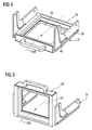
- FIGS. 4 and 5 show a further embodiment with which a beam-shaping element 33, for example a ripple filter, can be folded in and out into a horizontally extending particle beam 10B (more precisely into a possible beam path).
- the beam-shaping element 33 is fastened in a frame 35.
- the beam-shaping element 33 is in a horizontal parking position, from which it by means of a cam mechanism 37 can be brought into a vertical beam position.
- the required drive takes place, for example, via an unillustrated electric motor by translation of the frame 35 in a lower guide rail 39.
- the shape of an upper guide rail 40 causes the frame 35 to fold from the lower horizontal parking position into the upright beam position shown in FIG.
- Position change is reversible and can be carried out quickly due to the short travel.
- This embodiment has the advantage that it requires space essentially only in the beam direction.
- Position monitoring takes place, for example, via limit switches, which indicate the parking position and the beam position.
- a continuous position determination can take place via an encoder.
- FIGS. 6 and 7. A further embodiment is shown in FIGS. 6 and 7.
- a frame structure 41 is used which has space for at least 1 passive beam-shaping element 42 and possibly also an empty position (without beam-shaping element).
- a beam-shaping element is provided for each particle type, which have a fixed distance from one another in the frame 41.
- particle-specific beam-shaping elements or no beam-shaping element
- frame portions located outside the guide 43 can be folded away laterally.
- a drive of the frame structure e.g. done via an electric motor.
- the position change of the beam-shaping elements is reversible, automated and quickly carried out.
- Positioning of the frame structure 41 can also be continuous or discrete.
- a particle therapy facility on different irradiation modes with different Particle types can be set in a short time. This eliminates a time-consuming manual intervention of an operator, the length of stay of a patient at the radiation therapy space is reduced and increases the patient throughput. Furthermore, the patient irradiation can be particle-specifically optimized with regard to the workflow, and it can be incorrect assembly of beam-shaping elements by the automated control and monitoring of the device can be avoided.
Landscapes
- Health & Medical Sciences (AREA)
- Engineering & Computer Science (AREA)
- Biomedical Technology (AREA)
- Physics & Mathematics (AREA)
- General Health & Medical Sciences (AREA)
- Radiology & Medical Imaging (AREA)
- Life Sciences & Earth Sciences (AREA)
- Animal Behavior & Ethology (AREA)
- Nuclear Medicine, Radiotherapy & Molecular Imaging (AREA)
- Public Health (AREA)
- Veterinary Medicine (AREA)
- Pathology (AREA)
- Spectroscopy & Molecular Physics (AREA)
- General Engineering & Computer Science (AREA)
- High Energy & Nuclear Physics (AREA)
- Radiation-Therapy Devices (AREA)
- Particle Accelerators (AREA)
Abstract
Description
Die Erfindung betrifft eine Partikelbeschleunigeranlage zur Beschleunigung von mindestens zwei Partikelarten, wobei in einem ersten Betriebszustand eine erste Partikelart und in einem zweiten Betriebszustand eine zweite Partikelart beschleunigt werden. Ferner betrifft die Erfindung eine Vorrichtung zur Anpassung eines Partikelstrahlparameters eines Partikelstrahls einer derartigen Partikelbeschleunigeranlage.The invention relates to a particle accelerator system for accelerating at least two types of particles, wherein in a first operating state a first particle type and in a second operating state a second particle type are accelerated. Furthermore, the invention relates to a device for adapting a particle beam parameter of a particle beam of such a particle accelerator system.
Aus
Neben dem Aufbau zweier getrennter Ionenquelle entsprechend
Bei der Strahlentherapie wird bei einer Bestrahlungssitzung ein Patient an einem Behandlungsplatz positioniert und seine Positionierung in Hinblick auf die der Therapieplanung zugrunde liegende Position verifiziert. Anschließend erfolgt eine Bestrahlung aus einer oder mehreren Einfallsrichtungen mit Partikeln, beispielsweise Protonen, Pionen, Helium-, Kohlenstoff- oder Sauerstoff-Ionen.Radiation therapy involves positioning a patient at a treatment site during an irradiation session and verifying his positioning with respect to the underlying therapeutic planning position. Subsequently, irradiation takes place from one or more incident directions with particles, for example protons, pions, helium, carbon or oxygen ions.
Bei Partikeltherapieanlagen, wie sie z.B. durch die
Ein Ripple-Filter ist beispielsweise aus der Veröffentlichung von
Ferner ist beispielsweise aus der
Verschiedene Bestrahlungsanlagen und -techniken sind von
Eine Aufgabe der Erfindung liegt darin, die im Arbeitsablauf beim Betreiben einer Partikelbeschleunigeranlage, insbesondere einer Partikeltherapieanlage, im Hinblick auf die Verwendung verschiedener Partikelarten zu vereinfachen.An object of the invention is to simplify the workflow in the operation of a particle accelerator, in particular a particle therapy system, with regard to the use of different types of particles.
Eine weitere Aufgabe der Erfindung liegt darin, eine partikelspezifische Anpassung eines Partikelstrahlparameters eines Partikelstrahls zu vereinfachen.Another object of the invention is to simplify a particle-specific adaptation of a particle beam parameter of a particle beam.
Diese Aufgabe wird erfindungsgemäß gelöst durch eine Vorrichtung zur Anpassung mindestens eines Partikelstrahlparameters eines Partikelstrahls einer Partikelbeschleunigeranlage, die mindestens in zwei Betriebszuständen betrieben werden kann, wobei in einem ersten Betriebszustand eine erste Partikelart und in einem zweiten Betriebszustand eine zweite Partikelart beschleunigt werden, wobei die Vorrichtung ein erstes von einer Halterungseinheit gehaltenes Strahlformungselement umfasst, wobei das Strahlformungselement den Partikelstrahlparameter anpasst und wobei die Halterungseinheit zum Positionieren des ersten Strahlformungselements in Abhängigkeit vom Betriebszustand ausgebildet ist, so dass das erste Strahlformungselement im ersten Betriebszustand von Partikeln durchstrahlt und im zweiten Betriebszustand nicht von Partikeln durchstrahlt wird.This object is achieved according to the invention by a device for adapting at least one particle beam parameter of a particle beam of a particle accelerator system which can be operated at least in two operating states, wherein in a first operating state a first particle type and in a second operating state a second particle type are accelerated, wherein the device first beam forming element held by a holding unit, wherein the beam shaping element adapts the particle beam parameter and wherein the holding unit is designed for positioning the first beam shaping element depending on the operating state, so that the first beam shaping element is irradiated by particles in the first operating state and is not irradiated by particles in the second operating state ,
Die Aufgabe bezogen auf die eingangs erwähnte Partikelbeschleunigeranlage wird durch eine Partikelbeschleunigeranlage nach Anspruch 5 gelöst.The object relating to the particle accelerator system mentioned above is achieved by a particle accelerator system according to claim 5.
Ein Vorteil einer erfindungsgemäßen Vorrichtung zur Anpassung eines Partikelstrahlparameters oder deren Verwendung in einer Partikelbeschleunigeranlage liegt darin, dass die manuelle und entsprechend zeitaufwändige Positionierung eines Strahlformungselements entfällt und mithilfe der Halterungseinheit und insbesondere einem Verstellmechanismus automatisiert vorgenommen werden kann. Dies erlaubt es, einen Patienten mit verschiedenen Partikelarten zu bestrahlen, ohne dass ein Austausch eines partikelspezifischen Strahlformungselements manuell vorgenommen werden muss. D.h., die Anpassung des Partikelstrahls mit Hilfe eines Strahlformungselements kann beispielsweise von einem Therapiekontrollzentrum der Partikeltherapieanlage aus veranlasst werden. Dadurch entfällt die zeitaufwändige Unterbrechung für einen Austausch von Strahlformungselementen. Dies vereinfacht den Bestrahlungsvorgang und entlastet die Überwachung des Bestrahlungsplatzes hinsichtlich der Anwesenheit von Bedienpersonal.An advantage of a device according to the invention for adapting a particle beam parameter or its use in a particle accelerator system is that the manual and correspondingly time-consuming positioning of a beam-shaping element is eliminated and automated by means of the support unit and in particular an adjustment mechanism. This makes it possible to irradiate a patient with different particle types, without having to manually replace a particle-specific beam-shaping element. That is to say, the adaptation of the particle beam with the aid of a beam-shaping element can be initiated, for example, by a therapy control center of the particle therapy system. This eliminates the time-consuming interruption for an exchange of beamforming elements. This simplifies the irradiation process and relieves the monitoring of the irradiation site with regard to the presence of operating personnel.
Bei der Verwendung einer Ausführungsform der Erfindung in Kombination mit Rasterscanverfahren wird z.B. eine Anzahl von partikelspezifischen Strahlformungselementen bereitgehalten, welche nicht patientenspezifisch sind. Die Patientenunabhängigkeit erlaubt es, die Anpassung der Partikeltherapieanlage beim Wechsel zwischen Patienten oder/und Partikelarten zu automatisieren.When using an embodiment of the invention in combination with raster scan methods, e.g. a number of particle specific beamforming elements are provided that are not patient specific. Patient independence makes it possible to automate the adaptation of the particle therapy system when switching between patients and / or particle types.
In einer vorteilhaften Ausbildungsform einer Vorrichtung zur Anpassung des Strahlparameters weist diese eine automatische Antriebseinheit zur Positionierung mindestens eines Strahlformungselements auf, wobei in einer besonders vorteilhaften Ausführungsform Positionssensoren zur Positionsüberwachung des oder der Strahlformungselemente vorhanden sind.In an advantageous embodiment of a device for adjusting the beam parameter, the latter has an automatic drive unit for positioning at least one beam-shaping element, wherein in a particularly advantageous embodiment position sensors for position monitoring of the beam-shaping element or elements are present.
In einer weiteren vorteilhaften Ausführungsform der Vorrichtung weist diese ein zweites, von der Halterungseinheit gehaltenes Strahlformungselement auf, das den gleichen und/oder einen anderen Strahlparameter beeinflusst, das ferner fest mit dem ersten Strahlformungselement verbunden oder unabhängig vom ersten Strahlformungselement bewegbar ist und das insbesondere derart positionierbar ist, dass das zweite Strahlformungselement im zweiten Betriebszustand von Partikeln durchstrahlt und im ersten Betriebszustand von Partikeln nicht durchstrahlt wird. Dies ermöglicht es, den Betrieb der Partikeltherapieanlage automatisiert partikelspezifisch durchzuführen, da im jeweiligen Betriebszustand nur die Strahlelemente für die jeweilige Partikelart automatisiert in den Partikelstrahl gebracht werden. D.h., diese Ausführungsform hat den Vorteil, dass bei zwei oder mehreren Strahlformungselementen die Strahlparameter mehrerer Partikelarten partikelspezifisch modifiziert und angepasst werden können. Mögliche Strahlformungselemente sind dabei beispielsweise Ripple-Filter zur Aufweitung der Partikelenergieverteilung des Partikelstrahls, ein Strahlkollimator zur Begrenzung des Partikelstrahls in seiner radialen Ausdehnung, ein Reichweitenverschieber zur Anpassung der Partikelenergie, ein Bolus zur Reichenweitenanpassung der hinteren Dosisverteilung an einen Tumor oder ein Streuelement zur Strahlaufweitung.In a further advantageous embodiment of the device, the latter has a second beam-shaping element held by the holding unit, which influences the same and / or a different beam parameter, which is also fixedly connected to the first beam-shaping element or movable independently of the first beam-shaping element and which in particular can be positioned in this way is that the second beam-shaping element is irradiated by particles in the second operating state and is not irradiated by particles in the first operating state. This makes it possible to carry out the operation of the particle therapy system automatically particle-specific, since in the respective operating state, only the beam elements for each type of particle are automatically brought into the particle beam. That is, this embodiment has the advantage that with two or more beam-shaping elements, the beam parameters of several particle types can be particle-specifically modified and adapted. Possible beam-shaping elements are, for example, ripple filters for widening the particle energy distribution the particle beam, a beam collimator for limiting the particle beam in its radial extent, a range shifter for adjusting the particle energy, a bolus for adjusting the range of the rear dose distribution to a tumor or a scattering element for beam expansion.
Weitere vorteilhafte Ausführungsformen der Erfindung sind durch die Merkmale der Unteransprüche gekennzeichnet.Further advantageous embodiments of the invention are characterized by the features of the subclaims.
Es folgt die Erläuterung von mehreren Ausführungsbeispielen der Erfindung anhand der Figuren 1 bis 6. Es zeigen:
- FIG 1
- eine schematisch dargestellte Partikeltherapieanlage,
- FIG 2 und 3
- eine erste Ausführungsform einer Vorrichtung zur Anpassung eines Partikelstrahlparameters,
- FIG 4 und 5
- eine zweite Ausführungsform einer derartigen Vorrichtung und
- FIG 6 und 7
- eine dritte Ausführungsform einer derartigen Vorrichtung.
- FIG. 1
- a schematically illustrated particle therapy system,
- FIGS. 2 and 3
- A first embodiment of a device for adapting a particle beam parameter,
- 4 and 5
- a second embodiment of such a device and
- FIGS. 6 and 7
- a third embodiment of such a device.
Figur 1 zeigt schematisch eine Partikeltherapieanlage 1 wie sie z.B. aus
Die Partikeltherapieanlage 1 umfasst auf der Beschleunigerseite 4 zwei Partikelquellen 5A und 5B sowie eine Vakuumstrahlführungs- und Beschleunigungssystem 7. Dieses umfasst beispielhaft auch eine Rasterscanvorrichtung 9. Ein derartiger Aufbau ist darauf ausgelegt, verschiedene Partikelarten der Partikelquellen 5A und 5B auf Energien von einigen hundert MeV zu beschleunigen und mindestens einem Strahlentherapieplatz 15 zuzuführen.The
Bei der Bestrahlung wird ein Partikelstrahl 10 auf einen auf einer Liege 11 positionierten Patienten 13 gerichtet. Der Strahlentherapieplatz 15 umfasst eine Patientenpositioniervorrichtung (nicht eingezeichnet), die es ermöglicht, den Patienten 13 mit dem zu bestrahlenden Gewebe in einem Isozentrum 17 des Strahlentherapieplatzes 15 zu positionieren. Der Partikelstrahl 10 durchläuft vorzugsweise in einer Nullstellung der Rasterscanvorrichtung 9 das Isozentrum 17.During irradiation, a
Zur Strahlüberwachung umfasst die Partikeltherapieanlage 1 ferner ein Strahlüberwachungssystem 19, das beispielsweise die Strahlposition und Strahlintensität überwacht. Das Strahlüberwachungssystem 19 ist zwischen dem Patienten 13 und dem Strahlaustritt aus dem Vakuum-Strahlführungs- und Beschleunigungssystem 7 angeordnet. Die Vorrichtung 3 zur Anpassung mindestens eines Partikelstrahlparameters ist vorzugsweise dem Strahlüberwachungssystem 19 in Strahlrichtung nachgelagert. Sie erlaubt es, einen Partikelstrahlparameter auf die jeweils gerade verwendete Partikelart anzupassen, d.h., sie stellt Strahlformungselemente für verschiedene Partikelarten zur Verfügung.For beam monitoring, the
Die Vorrichtung 3 wird vorzugsweise in einem kompakten Aufbau ausgeführt, um möglichst wenig Platz einzunehmen und von außen z.B. für die Wartung gut zugänglich zu sein.The
Die Vorrichtung 3 erlaubt es, Strahlformungselemente partikelspezifisch in Abhängigkeit vom Betriebszustand zu positionieren, so dass z.B. ein erste Strahlformungselement von Partikeln des ersten Betriebszustands durchstrahlt und von Partikeln des zweiten Betriebszustands nicht durchstrahlt wird und dass ein zweites Strahlformungselement von Partikeln des ersten Betriebszustands nicht durchstrahlt und von Partikeln des zweiten Betriebszustands durchstrahlt wird. Dazu werden die Strahlformungselemente bei Bedarf im Partikelstrahl, z.B. im Verlauf des Partikelstrahls im Scanbereich, positioniert. Mögliche funktionelle Ausbildungen der Vorrichtung 3 werden in den folgenden Figuren anhand von Ausführungsbeispielen näher erläutert.The
Figur 2 zeigt eine Skizze einer Vorrichtung, in der zwei Strahlformungselemente 21, 23 unabhängig voneinander in einer Ebene bewegt werden können. Die Strahlformungselemente 21, 23 werden von einer Halterungseinheit 25 gehaltert, die beispielsweise ein Führungssystem 27 aufweist. Die Strahlformungselemente 21 und 23 werden mit Hilfe einer Antriebsvorrichtung 28 (siehe Figur 3) einzeln zwischen einer Parkposition und einer Strahlposition 29 verfahren. Die Strahlformungselemente 21 und 23 befinden sich in Figur 2 jeweils in ihren Parkpositionen. Die eingenommenen Positionen werden durch Sensoren, z.B. durch einen Sensor 30, detektiert.Figure 2 shows a sketch of a device in which two beam-shaping
Ferner sind in Figur 2 schematisch ein Strahlaustritt 31 aus der Vakuumstrahlführungs- und Beschleunigungseinheit und ein Partikelstrahl 10A angedeutet. Vorzugsweise wird die tatsächliche Lage des bzw. der Strahlformungselemente 21, 23 durch mindestens einen unabhängigen Sensor kontinuierlich (z.B. mit einem Encoder) oder diskret (z.B. durch einen Endschalter, hier der Sensor 30) überwacht.Furthermore, a
Figur 3 zeigt eine räumliche Darstellung der Vorrichtung aus Figur 2 in einem Betriebszustand, bei dem eines der Strahlformungselemente durchleuchtet wird. Dabei wurde beispielsweise das Strahlformungselement 21 mithilfe der Antriebsvorrichtung 28 in die Strahlposition 29 gebracht. Die Antriebsvorrichtung umfasst z.B. ein mit einem Elektromotor angetriebenes Riemensystem 32.FIG. 3 shows a spatial representation of the device from FIG. 2 in an operating state in which one of the beam-shaping elements is transilluminated. In this case, for example, the beam-shaping
Die Figuren 4 und 5 zeigen eine weitere Ausführungsform, mit der ein Strahlformungselement 33, z.B. ein Ripple-Filter, in einen horizontal verlaufenden Partikelstrahl 10B (genauer in einen möglichen Strahlverlauf) ein- und ausgeklappt werden kann. Dazu ist das Strahlformungselement 33 in einem Rahmen 35 befestigt. In Figur 3 befindet sich das Strahlformungselement 33 in einer horizontalen Parkposition, aus der es mittels eines Kurvengetriebes 37 in eine senkrechte Strahlposition bringbar ist. Der benötigte Antrieb erfolgt beispielsweise über einen nicht abgebildeten Elektromotor durch Translation des Rahmens 35 in einer unteren Führschiene 39. Durch die Ausformung einer oberen Führschiene 40 klappt der Rahmen 35 aus der unteren horizontalen Parkposition in die in Figur 5 abgebildete aufrechte Strahlposition. Der Positionswechsel ist reversibel und kann aufgrund des kurzen Verfahrweges schnell durchgeführt werden. Diese Ausführungsform hat den Vorteil, dass sie im Wesentlichen nur in Strahlrichtung Platz benötigt. Eine Positionsüberwachung erfolgt z.B. wieder über Endschalter, die die Parkposition und die Strahlposition anzeigen. Optional kann eine kontinuierliche Positionsbestimmung über einen Encoder erfolgen.FIGS. 4 and 5 show a further embodiment with which a beam-shaping
Eine weitere Ausführungsform ist den Figuren 6 und 7 zu entnehmen. Dabei wird eine Rahmenstruktur 41 verwendet, die Platz für mindestens 1 passives Strahlformungselement 42 und evtl. auch eine Leerposition (ohne Strahlformungselement) aufweist. Vorzugsweise wird für jede Partikelart ein Strahlformungselement vorgesehen, die im Rahmen 41 einen festen Abstand zueinander aufweisen. Durch ein Verschieben der Rahmenstruktur 41 entlang einer Führung 43 werden partikelspezifisch Strahlformungselemente (oder auch kein Strahlformungselement) im Partikelstrahl positioniert. In einer vorteilhaften Ausführungsform können Rahmenbereiche, die sich außerhalb der Führung 43 befinden, seitlich weggeklappt werden. Auch hier kann ein Antrieb der Rahmenstruktur z.B. über einen Elektromotor erfolgen. Der Positionswechsel der Strahlformungselemente ist reversibel, automatisiert und schnell durchführbar. Eine Positionsbestimmung der Rahmenstruktur 41 kann ebenfalls kontinuierlich oder diskret erfolgen.A further embodiment is shown in FIGS. 6 and 7. In this case, a
Für alle möglichen Ausführungsformen gilt, dass durch die Automatisierung des Positionswechsel- und Austauschprozesses und die Verwendung von, auf die verschiedenen Partikelarten ausgelegten, Strahlformungselemente kann eine Partikeltherapieanlage auf verschiedene Bestrahlungsmoden mit unterschiedlichen Partikelarten in kurzer Zeit eingestellt werden. Dadurch entfällt eine zeitaufwändige manuelle Intervention eines Bedieners, die Aufenthaltsdauer eines Patienten am Strahlentherapieplatz wird reduziert und der Patientendurchsatz erhöht. Ferner kann die Patientenbestrahlung partikelspezifisch hinsichtlich des Arbeitsablaufes optimiert werden, und es können Fehlmontagen von Strahlformungselementen durch die automatisierte Ansteuerung und Überwachung der Vorrichtung vermieden werden.For all possible embodiments, by automating the position change and exchange process and the use of, designed for the different particle types, beam shaping elements, a particle therapy facility on different irradiation modes with different Particle types can be set in a short time. This eliminates a time-consuming manual intervention of an operator, the length of stay of a patient at the radiation therapy space is reduced and increases the patient throughput. Furthermore, the patient irradiation can be particle-specifically optimized with regard to the workflow, and it can be incorrect assembly of beam-shaping elements by the automated control and monitoring of the device can be avoided.
Claims (9)
Priority Applications (6)
| Application Number | Priority Date | Filing Date | Title |
|---|---|---|---|
| EP05017626A EP1752992A1 (en) | 2005-08-12 | 2005-08-12 | Apparatus for the adaption of a particle beam parameter of a particle beam in a particle beam accelerator and particle beam accelerator with such an apparatus |
| US11/997,989 US7812326B2 (en) | 2005-08-12 | 2006-08-08 | Treatment station for particle therapy |
| EP06778187A EP1913603B1 (en) | 2005-08-12 | 2006-08-08 | Treatment station for particle bombardment of a patient and a particle therapy installation |
| PCT/EP2006/065128 WO2007020212A1 (en) | 2005-08-12 | 2006-08-08 | Treatment station for particle bombardment of a patient and a particle therapy installation |
| AT06778187T ATE504926T1 (en) | 2005-08-12 | 2006-08-08 | TREATMENT STATION FOR PARTICLE BOMBARDING A PATIENT AND PARTICLE THERAPY INSTALLATION |
| DE602006021190T DE602006021190D1 (en) | 2005-08-12 | 2006-08-08 | TREATMENT STATION FOR PARTICLE BOMBING OF A PATIENT AND PARTIAL THERAPY INSTALLATION |
Applications Claiming Priority (2)
| Application Number | Priority Date | Filing Date | Title |
|---|---|---|---|
| US70778305P | 2005-08-12 | 2005-08-12 | |
| EP05017626A EP1752992A1 (en) | 2005-08-12 | 2005-08-12 | Apparatus for the adaption of a particle beam parameter of a particle beam in a particle beam accelerator and particle beam accelerator with such an apparatus |
Publications (1)
| Publication Number | Publication Date |
|---|---|
| EP1752992A1 true EP1752992A1 (en) | 2007-02-14 |
Family
ID=36951994
Family Applications (2)
| Application Number | Title | Priority Date | Filing Date |
|---|---|---|---|
| EP05017626A Withdrawn EP1752992A1 (en) | 2005-08-12 | 2005-08-12 | Apparatus for the adaption of a particle beam parameter of a particle beam in a particle beam accelerator and particle beam accelerator with such an apparatus |
| EP06778187A Not-in-force EP1913603B1 (en) | 2005-08-12 | 2006-08-08 | Treatment station for particle bombardment of a patient and a particle therapy installation |
Family Applications After (1)
| Application Number | Title | Priority Date | Filing Date |
|---|---|---|---|
| EP06778187A Not-in-force EP1913603B1 (en) | 2005-08-12 | 2006-08-08 | Treatment station for particle bombardment of a patient and a particle therapy installation |
Country Status (5)
| Country | Link |
|---|---|
| US (1) | US7812326B2 (en) |
| EP (2) | EP1752992A1 (en) |
| AT (1) | ATE504926T1 (en) |
| DE (1) | DE602006021190D1 (en) |
| WO (1) | WO2007020212A1 (en) |
Cited By (4)
| Publication number | Priority date | Publication date | Assignee | Title |
|---|---|---|---|---|
| DE102007020599A1 (en) * | 2007-05-02 | 2008-11-06 | Siemens Ag | Particle therapy system |
| DE102007033894B3 (en) * | 2007-07-20 | 2008-12-11 | Siemens Ag | Particle beam application device, irradiation device and method for guiding a particle beam |
| DE102008058299A1 (en) * | 2008-11-20 | 2010-05-27 | Siemens Aktiengesellschaft | Apparatus and method for reducing beam expansion of radiation |
| DE102012210241A1 (en) * | 2012-06-18 | 2013-12-19 | Siemens Aktiengesellschaft | Method for optimizing irradiation to patient using particle irradiation unit, involves positioning patient to secondary irradiation position and performing secondary irradiation in time same as that of primary irradiation |
Families Citing this family (27)
| Publication number | Priority date | Publication date | Assignee | Title |
|---|---|---|---|---|
| EP2259664B1 (en) | 2004-07-21 | 2017-10-18 | Mevion Medical Systems, Inc. | A programmable radio frequency waveform generator for a synchrocyclotron |
| EP2389981A3 (en) | 2005-11-18 | 2012-03-07 | Still River Systems, Inc. | Charged particle radiation therapy |
| US8581523B2 (en) | 2007-11-30 | 2013-11-12 | Mevion Medical Systems, Inc. | Interrupted particle source |
| US8933650B2 (en) | 2007-11-30 | 2015-01-13 | Mevion Medical Systems, Inc. | Matching a resonant frequency of a resonant cavity to a frequency of an input voltage |
| DE102009017440A1 (en) * | 2009-04-15 | 2010-10-28 | Siemens Aktiengesellschaft | Arrangement for expanding the particle energy distribution of a particle beam, particle therapy system and method for expanding the particle energy distribution of a particle beam |
| WO2012161852A2 (en) | 2011-03-07 | 2012-11-29 | Loma Linda University Medical Center | Systems, devices and methods related to calibration of a proton computed tomography scanner |
| CN104812444B (en) | 2012-09-28 | 2017-11-21 | 梅维昂医疗系统股份有限公司 | The energy adjustment of the particle beams |
| CN104813749B (en) | 2012-09-28 | 2019-07-02 | 梅维昂医疗系统股份有限公司 | Control the intensity of the particle beams |
| US9681531B2 (en) | 2012-09-28 | 2017-06-13 | Mevion Medical Systems, Inc. | Control system for a particle accelerator |
| US10254739B2 (en) | 2012-09-28 | 2019-04-09 | Mevion Medical Systems, Inc. | Coil positioning system |
| US9622335B2 (en) | 2012-09-28 | 2017-04-11 | Mevion Medical Systems, Inc. | Magnetic field regenerator |
| JP6254600B2 (en) | 2012-09-28 | 2017-12-27 | メビオン・メディカル・システムズ・インコーポレーテッド | Particle accelerator |
| TW201422279A (en) | 2012-09-28 | 2014-06-16 | Mevion Medical Systems Inc | Focusing a particle beam |
| TW201433331A (en) | 2012-09-28 | 2014-09-01 | Mevion Medical Systems Inc | Adjusting coil position |
| TW201438787A (en) | 2012-09-28 | 2014-10-16 | Mevion Medical Systems Inc | Controlling particle therapy |
| US8791656B1 (en) | 2013-05-31 | 2014-07-29 | Mevion Medical Systems, Inc. | Active return system |
| US9730308B2 (en) | 2013-06-12 | 2017-08-08 | Mevion Medical Systems, Inc. | Particle accelerator that produces charged particles having variable energies |
| CN110237447B (en) | 2013-09-27 | 2021-11-02 | 梅维昂医疗系统股份有限公司 | Particle therapy system |
| US10675487B2 (en) | 2013-12-20 | 2020-06-09 | Mevion Medical Systems, Inc. | Energy degrader enabling high-speed energy switching |
| US9962560B2 (en) | 2013-12-20 | 2018-05-08 | Mevion Medical Systems, Inc. | Collimator and energy degrader |
| US9661736B2 (en) | 2014-02-20 | 2017-05-23 | Mevion Medical Systems, Inc. | Scanning system for a particle therapy system |
| US9950194B2 (en) | 2014-09-09 | 2018-04-24 | Mevion Medical Systems, Inc. | Patient positioning system |
| US10786689B2 (en) | 2015-11-10 | 2020-09-29 | Mevion Medical Systems, Inc. | Adaptive aperture |
| US10925147B2 (en) | 2016-07-08 | 2021-02-16 | Mevion Medical Systems, Inc. | Treatment planning |
| US11103730B2 (en) | 2017-02-23 | 2021-08-31 | Mevion Medical Systems, Inc. | Automated treatment in particle therapy |
| EP3645111A1 (en) | 2017-06-30 | 2020-05-06 | Mevion Medical Systems, Inc. | Configurable collimator controlled using linear motors |
| WO2020185544A1 (en) | 2019-03-08 | 2020-09-17 | Mevion Medical Systems, Inc. | Delivery of radiation by column and generating a treatment plan therefor |
Citations (6)
| Publication number | Priority date | Publication date | Assignee | Title |
|---|---|---|---|---|
| US3500043A (en) * | 1966-05-13 | 1970-03-10 | Hanssen Karl Josef | Method for high contrast imaging of phase or amplitude objects in a corpuscular ray device,such as an electron microscope |
| US4528453A (en) * | 1982-07-30 | 1985-07-09 | Albert Einstein College Of Medicine Of Yeshiva University | Dual collimator |
| US5440133A (en) | 1993-07-02 | 1995-08-08 | Loma Linda University Medical Center | Charged particle beam scattering system |
| EP0986070A1 (en) * | 1998-09-11 | 2000-03-15 | Gesellschaft für Schwerionenforschung mbH | Ion beam therapy system and a method for operating the system |
| EP1213744A2 (en) * | 2000-12-06 | 2002-06-12 | Ulvac, Inc. | Ion implantation systems and methods |
| US20040094725A1 (en) * | 2001-03-28 | 2004-05-20 | Jacques Gierak | Device for generating an ion beam |
Family Cites Families (6)
| Publication number | Priority date | Publication date | Assignee | Title |
|---|---|---|---|---|
| US4112306A (en) * | 1976-12-06 | 1978-09-05 | Varian Associates, Inc. | Neutron irradiation therapy machine |
| JP2824363B2 (en) * | 1992-07-15 | 1998-11-11 | 三菱電機株式会社 | Beam supply device |
| US6607489B2 (en) * | 2001-04-05 | 2003-08-19 | General Electric Company | Focus correction for ultrasound imaging through mammography compression plate |
| JP3685194B2 (en) * | 2003-09-10 | 2005-08-17 | 株式会社日立製作所 | Particle beam therapy device, range modulation rotation device, and method of attaching range modulation rotation device |
| JP4114590B2 (en) * | 2003-10-24 | 2008-07-09 | 株式会社日立製作所 | Particle beam therapy system |
| JP3643371B1 (en) * | 2003-12-10 | 2005-04-27 | 株式会社日立製作所 | Method of adjusting particle beam irradiation apparatus and irradiation field forming apparatus |
-
2005
- 2005-08-12 EP EP05017626A patent/EP1752992A1/en not_active Withdrawn
-
2006
- 2006-08-08 DE DE602006021190T patent/DE602006021190D1/en active Active
- 2006-08-08 WO PCT/EP2006/065128 patent/WO2007020212A1/en active Application Filing
- 2006-08-08 US US11/997,989 patent/US7812326B2/en not_active Expired - Fee Related
- 2006-08-08 AT AT06778187T patent/ATE504926T1/en active
- 2006-08-08 EP EP06778187A patent/EP1913603B1/en not_active Not-in-force
Patent Citations (7)
| Publication number | Priority date | Publication date | Assignee | Title |
|---|---|---|---|---|
| US3500043A (en) * | 1966-05-13 | 1970-03-10 | Hanssen Karl Josef | Method for high contrast imaging of phase or amplitude objects in a corpuscular ray device,such as an electron microscope |
| US4528453A (en) * | 1982-07-30 | 1985-07-09 | Albert Einstein College Of Medicine Of Yeshiva University | Dual collimator |
| US5440133A (en) | 1993-07-02 | 1995-08-08 | Loma Linda University Medical Center | Charged particle beam scattering system |
| EP0986070A1 (en) * | 1998-09-11 | 2000-03-15 | Gesellschaft für Schwerionenforschung mbH | Ion beam therapy system and a method for operating the system |
| EP0986071A2 (en) | 1998-09-11 | 2000-03-15 | Gesellschaft für Schwerionenforschung mbH | Ion beam therapy system and a method for operating the system |
| EP1213744A2 (en) * | 2000-12-06 | 2002-06-12 | Ulvac, Inc. | Ion implantation systems and methods |
| US20040094725A1 (en) * | 2001-03-28 | 2004-05-20 | Jacques Gierak | Device for generating an ion beam |
Non-Patent Citations (2)
| Title |
|---|
| H. BLATTMANN: "Beam delivery systems for charged particles", RADIAT. ENVIRON. BIOPHYS., vol. 31, 1992, pages 219 - 231 |
| U. WEBER; G. KRAFT: "Design and construction of a rip- ple filter for a smoothed depth dose distribution in confor- mal particle therapy", PHYS. MED. BIOL., vol. 44, 1999, pages 2765 - 2775 |
Cited By (6)
| Publication number | Priority date | Publication date | Assignee | Title |
|---|---|---|---|---|
| DE102007020599A1 (en) * | 2007-05-02 | 2008-11-06 | Siemens Ag | Particle therapy system |
| DE102007033894B3 (en) * | 2007-07-20 | 2008-12-11 | Siemens Ag | Particle beam application device, irradiation device and method for guiding a particle beam |
| DE102008058299A1 (en) * | 2008-11-20 | 2010-05-27 | Siemens Aktiengesellschaft | Apparatus and method for reducing beam expansion of radiation |
| US8198608B2 (en) | 2008-11-20 | 2012-06-12 | Siemens Aktiengesellschaft | Reducing the widening of a radiation beam |
| DE102012210241A1 (en) * | 2012-06-18 | 2013-12-19 | Siemens Aktiengesellschaft | Method for optimizing irradiation to patient using particle irradiation unit, involves positioning patient to secondary irradiation position and performing secondary irradiation in time same as that of primary irradiation |
| DE102012210241B4 (en) * | 2012-06-18 | 2014-11-27 | Siemens Aktiengesellschaft | Method and device for optimizing irradiation with a particle irradiation system having a plurality of jet outlets |
Also Published As
| Publication number | Publication date |
|---|---|
| EP1913603B1 (en) | 2011-04-06 |
| ATE504926T1 (en) | 2011-04-15 |
| US20080191152A1 (en) | 2008-08-14 |
| EP1913603A1 (en) | 2008-04-23 |
| WO2007020212A1 (en) | 2007-02-22 |
| US7812326B2 (en) | 2010-10-12 |
| DE602006021190D1 (en) | 2011-05-19 |
Similar Documents
| Publication | Publication Date | Title |
|---|---|---|
| EP1752992A1 (en) | Apparatus for the adaption of a particle beam parameter of a particle beam in a particle beam accelerator and particle beam accelerator with such an apparatus | |
| DE102005034912B4 (en) | Particle therapy system, method for determining control parameters of such a therapy system, radiotherapy planning device and irradiation method | |
| DE102005041122B3 (en) | Gantry system useful for particle therapy system for therapy plan and radiation method, particularly for irradiating volume, comprises first and second beam guiding devices guides particle beams | |
| DE102005044408B4 (en) | Particle therapy system, method and apparatus for requesting a particle beam | |
| EP2453984B1 (en) | Irradiation or irradiation planning system for a rescanning method using a particle beam | |
| DE10010523C2 (en) | Ion beam system for the irradiation of tumor tissue | |
| EP2022534B1 (en) | Control device for controlling an irradiation procedure, particle therapy facility and method for irradiating a target volume | |
| EP1524012B1 (en) | Device for positioning a patient | |
| DE102005053719B3 (en) | Particle therapy system, treatment plan and irradiation method for such a particle therapy system | |
| DE102007050168B3 (en) | Gantry, particle therapy system and method for operating a gantry with a movable actuator | |
| DE102005044409B4 (en) | Particle therapy system and method for forming a beam path for an irradiation process in a particle therapy system | |
| DE102006046193B3 (en) | Particle therapy facility for the particle therapy of a target volume exposed to a movement | |
| DE102007050035B4 (en) | Apparatus and method for deflecting a jet of electrically charged particles onto a curved particle path | |
| EP2273856A2 (en) | Accelerator assembly and method for adjusting a particle energy | |
| DE102009040031B4 (en) | Laser-driven particle beam irradiation apparatus and method | |
| EP1785161A1 (en) | Treatment room of a particle therapy system, treatment plan, method of creating a treatment plan, and method of irradiation treatment | |
| EP1764132A1 (en) | Method and device for configuring a beam path in a particle beam therapy system | |
| EP2177244A1 (en) | Assembly for irradiating patients with loaded particles and method for monitoring the assembly | |
| DE102010014002A1 (en) | Method for operating a particle therapy system | |
| EP2186498B1 (en) | Patient transport unit and method for transporting a patient | |
| EP2247339B1 (en) | Proton beam treatment system | |
| WO2012143134A1 (en) | Irradiation installation and control method for controlling same |
Legal Events
| Date | Code | Title | Description |
|---|---|---|---|
| PUAI | Public reference made under article 153(3) epc to a published international application that has entered the european phase |
Free format text: ORIGINAL CODE: 0009012 |
|
| AK | Designated contracting states |
Kind code of ref document: A1 Designated state(s): AT BE BG CH CY CZ DE DK EE ES FI FR GB GR HU IE IS IT LI LT LU LV MC NL PL PT RO SE SI SK TR |
|
| AX | Request for extension of the european patent |
Extension state: AL BA HR MK YU |
|
| RIN1 | Information on inventor provided before grant (corrected) |
Inventor name: USE, TIM Inventor name: RIETZEL, EIKE , DR. Inventor name: GROEZINGER, SVEN, OLIVER, DR. |
|
| AKX | Designation fees paid | ||
| STAA | Information on the status of an ep patent application or granted ep patent |
Free format text: STATUS: THE APPLICATION IS DEEMED TO BE WITHDRAWN |
|
| 18D | Application deemed to be withdrawn |
Effective date: 20070815 |
|
| REG | Reference to a national code |
Ref country code: DE Ref legal event code: 8566 |