EP1729389A1 - Conduit guiding device for flexible electrical or fluidic conduits - Google Patents
Conduit guiding device for flexible electrical or fluidic conduits Download PDFInfo
- Publication number
- EP1729389A1 EP1729389A1 EP06010131A EP06010131A EP1729389A1 EP 1729389 A1 EP1729389 A1 EP 1729389A1 EP 06010131 A EP06010131 A EP 06010131A EP 06010131 A EP06010131 A EP 06010131A EP 1729389 A1 EP1729389 A1 EP 1729389A1
- Authority
- EP
- European Patent Office
- Prior art keywords
- cable guide
- line
- guide device
- cable
- fastening
- Prior art date
- Legal status (The legal status is an assumption and is not a legal conclusion. Google has not performed a legal analysis and makes no representation as to the accuracy of the status listed.)
- Withdrawn
Links
Images


Classifications
-
- H—ELECTRICITY
- H02—GENERATION; CONVERSION OR DISTRIBUTION OF ELECTRIC POWER
- H02G—INSTALLATION OF ELECTRIC CABLES OR LINES, OR OF COMBINED OPTICAL AND ELECTRIC CABLES OR LINES
- H02G11/00—Arrangements of electric cables or lines between relatively-movable parts
- H02G11/006—Arrangements of electric cables or lines between relatively-movable parts using extensible carrier for the cable, e.g. self-coiling spring
-
- F—MECHANICAL ENGINEERING; LIGHTING; HEATING; WEAPONS; BLASTING
- F16—ENGINEERING ELEMENTS AND UNITS; GENERAL MEASURES FOR PRODUCING AND MAINTAINING EFFECTIVE FUNCTIONING OF MACHINES OR INSTALLATIONS; THERMAL INSULATION IN GENERAL
- F16L—PIPES; JOINTS OR FITTINGS FOR PIPES; SUPPORTS FOR PIPES, CABLES OR PROTECTIVE TUBING; MEANS FOR THERMAL INSULATION IN GENERAL
- F16L3/00—Supports for pipes, cables or protective tubing, e.g. hangers, holders, clamps, cleats, clips, brackets
- F16L3/01—Supports for pipes, cables or protective tubing, e.g. hangers, holders, clamps, cleats, clips, brackets for supporting or guiding the pipes, cables or protective tubing, between relatively movable points, e.g. movable channels
- F16L3/015—Supports for pipes, cables or protective tubing, e.g. hangers, holders, clamps, cleats, clips, brackets for supporting or guiding the pipes, cables or protective tubing, between relatively movable points, e.g. movable channels using articulated- or supple-guiding elements
-
- H—ELECTRICITY
- H02—GENERATION; CONVERSION OR DISTRIBUTION OF ELECTRIC POWER
- H02G—INSTALLATION OF ELECTRIC CABLES OR LINES, OR OF COMBINED OPTICAL AND ELECTRIC CABLES OR LINES
- H02G11/00—Arrangements of electric cables or lines between relatively-movable parts
Definitions
- the invention relates to a cable guide device for bendable electrical and / or fluidic lines, with at least one variable longitudinal course having cable guide strand, which is traversed in the longitudinal direction of at least one line-receiving channel.
- Machinery and mechanical systems are often equipped with linearly displacing components, which are to be supplied with electrical energy and / or fluidic media, the latter, for example, compressed air or hydraulic oil.
- electrical energy and / or fluidic media for example, compressed air or hydraulic oil.
- bendable electrical and / or fluidic lines are used, which can join the movement of the component to be supplied.
- the fluidic lines are, for example, bendable compressed air or hydraulic hoses, while the electrical lines are generally designed as single or multi-core bendable cables.
- the machines or installations may be equipped with a line guiding device which has a line guide line surrounding the lines in a protective manner, so that he is able to adapt his current shape to the relative position of the associated components of the machine or plant.
- Known wire guide device includes a chain-like cable management strand, which consists of a plurality of hingedly interconnected strand elements, so that variable course changes are possible within a plane.
- the known cable guide device also includes a rail-like guide device on which the cable guide strand can roll off.
- Within the cable management strand is a continuous line-receiving channel in which the lines to be led are housed together.
- a disadvantage of the known cable guide device are the relatively high production costs, which are caused, inter alia, by the cable guide strand consisting of many individual parts. After the production of the individual parts, these must be assembled consuming.
- the cable guide strand is formed of a material with rubber-elastic properties existing flexible profile part distributed over its circumference several each having a line receiving channel forming undercut longitudinal grooves with aufweitbarem by elastic deformation of the profile part Nuthals.
- the line guide strand can be very easily produced, for example by extrusion, as a one-piece profile part, wherein different strand lengths can be obtained by cutting from meter goods.
- line receiving channels formed in the profile part trained longitudinal grooves, which can be provided in an appropriate, if necessary specifically tailored to the particular application distribution and number.
- the feasibility of multiple independent line-receiving channels within one and the same profile part also allows, if necessary, to move several lines separately, which for example opens the possibility to separate fluidic and electrical lines from each other and thus in particular the risk of damage to an electrical Reduce line attributable short circuits.
- the flexible profile part has a relatively low specific weight by itself, in addition, in connection with the inherent inherent stability inherent in many cases, it will be possible to dispense with a separate external guide device. As a result, the costs to be incurred are reduced by a further not inconsiderable factor.
- Another advantage is the ease of assembly and disassembly of the leading lines. These do not have to be laboriously threaded through a channel which is closed all around, but can be easily pressed from the side through the elastically expandable groove neck of the relevant longitudinal groove.
- the wiring harness is made of a soft foam material.
- a realization of so-called sponge rubber has been found.
- the insertion of a line into the line-receiving channel is particularly simple if the Nuthals of the respective longitudinal groove has a widening to the outer surface of the line guide strand insertion section.
- serving for routing longitudinal grooves may be provided on only one or more of the four outer surfaces of the profile part.
- the cable guide device expediently contains one or more fastening elements.
- the fastener holds on the one hand the line guide strand and can be fastened to the other directly or indirectly to a supporting structure, which is usually a part of one of two relatively movable components.
- a plurality of fasteners are present, which engage at longitudinally spaced locations on the same line guide strand.
- two fastening elements can be assigned to each line guide strand be, each serving to fix one of the two end portions of the wiring harness.
- the fastening element which is preferably made of plastic material in a cost-effective manner, is expediently designed in the manner of a frame and surrounds the line guide strand to be fixed at the intended fastening point.
- the inner cross section of the fastening element and the outer cross section of the cable guide strand are suitably matched to one another such that the cable guide strand is enclosed under at least low prestressing and is thereby reliably held fast.
- the mounting of a fastener on the wiring harness is simplified when the fastener has a cross-sectionally U-shaped base and one of the base opening associated lid. With the cover removed, the wiring harness can be placed in the base. By subsequently closing the lid, the frame structure enclosing the cable guide strand results.
- the lid is pivotally mounted on the base and can be pivoted to open and close the fastener relative to the base.
- the bearing can be realized in particular by means of a one-piece solid-body joint.
- the fastening measures are simplified, in particular, when the line guide device has a plurality of line guide strands.
- the cable guide strand according to the invention is not only suitable for dynamic applications, but also for such a static nature. Thus, even if the cable guide strand during its use keeps its shape constant, its flexibility facilitates the production and laying work.
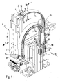
- Figures 1 and 2 show a machine device 1 operated using a fluidic medium and electrical energy in an exemplary embodiment.
- This device 1 is used for handling objects and in particular for converting such objects between two positions during a manufacturing or assembly process.
- the device 1 has inter alia a first device component 2, which is movable relative to a second device component 3 during operation.
- the first device component 2 can be displaced in an x-y plane relative to the second device component 3.
- the first device component 2 is supplied via electrical and fluidic lines 4 with electrical energy and a fluidic pressure medium, the latter in particular compressed air.
- These lines 4 are indicated in the individual drawing figures partially only dash-dotted lines.
- electrical lines 4a are concerned, they are designed in particular in the form of single or multi-core cables.
- the fluidic lines 4b are formed by tubes. In all cases, the lines 4 are flexible and easily bendable.
- the lines 4 extend between the two relative to each other movable device components 2, 3. Thus, this adjusts an orderly line routing and the lines 4 are particularly protected against damage from moving parts, the lines 4 are laid in one or more glovess Equipmentsstr brieflyen 5, the Part of a generally designated by reference numeral 6 cable guide means are equipped with the machine device 1.
- One and the same machine device 1 can have only one or several cable guide strands 5 at a time.
- Each line strand 5 is fixed at two spaced locations - hereinafter referred to as the first and second attachment point 7a, 7b - fixed to each one of the two device components 2, 3. These fastening points 7a, 7b are located in particular at the mutually opposite end sections of a respective line guide strand 5.
- the cable guide strands 5 are each formed in one piece by a flexible profile part consisting of material with rubber-elastic properties. Due to its flexibility, the cable guide strand 5 can be easily bent, so that changes its longitudinal course. Such a variation of the longitudinal course is automatically established during the relative movement between the two device components 2, 3, because in this case also the relative position between the first and second attachment points 7a, 7b of a respective line guide strand 5 changes.
- the cable guide strands 5 are laid so that they have a linear and a curved course in sections.
- the length of the linear sections changes with a simultaneous change in position of the curved section. Due to the high flexibility, the change in shape takes place within the framework of a harmonious sequence of movements.
- the lines 4 extend in line receiving channels 8, of which each line guide strand 5 has a plurality and the enforce the relevant line guide strand 5 parallel to its longitudinal axis in the longitudinal direction, where they open at the two opposite end faces of a respective line guide strand 5.
- the lines 4 extending in the line receiving channels 8 pass out of the line receiving channels 8 in the region of the frontal side openings and run from there to associated connection points of the relevant device components 2, 3, not shown. Due to their flexibility, the lines 4 can change their shape the elastic cable guide strands 5 easily join.
- the line receiving channels 8 are formed by undercut longitudinal grooves 14 which are distributed over the circumference of a respective line guide strand 5 formed in this. More specifically, in the embodiment, the respective line receiving channel 8 is formed by the relative to the associated Nuthals 15 deeper in the line guide strand 5 inner portion 16 of the respective longitudinal groove 14 whose diameter is greater than the width of the Nuthalses 15 at its narrowest point.
- the transverse dimensions of the arranged in the line receiving channels 8 lines 4 are greater than the width of the associated Nuthalses 15.
- the insertion into a line-receiving channel 8 is done by the Nuthals 15 therethrough, which is widened due to elastic deformation of the profile part material for a short time.
- a line 4 can be easily withdrawn sideways if necessary through the Nuthals 15 from a line-receiving channel 8.
- the inner portions 16 of the longitudinal grooves 14 are also contoured circular in the embodiment. It is considered ideal if in each line-receiving channel 8 only a single line 4 extends, wherein the cross section of the inner portion 16 is tuned to the line cross-section, that the inner portion 16 with its wall - apart from the condition caused by the Nuthals 15 gap - Rests all around the outer circumference of the contained line 4.
- the cross-sectional dimensions can in particular be chosen so that the inserted line 4 is biased by the line guide strand 5 forming profile part is biased.
- the Nuthälse 15 each with a widening insertion section 17 to the outer surface of the line guide strand 5.
- the insertion section 17 may be designed to taper in the direction of the inner section 16 in the manner of a funnel.
- the profile part can be produced very inexpensively by extruding rubber or plastic material.
- a production in endless goods or by the meter may be provided, wherein the resultant strand material is then cut to the desired strand length from case to case.
- the cable guide strand 5 forming profile part is particularly suitable for foam. It is expedient to use a flexible foam material, in particular a flexible polyurethane foam.
- the cable guide strands 5 made of sponge rubber.
- the distribution of the longitudinal grooves 14 along the circumference of the line guide strand 5 is based on the respective needs and takes into account in particular the cross-sectional dimensions of the required line receiving channels 8. It has proved to be particularly useful if the profile guide 5 forming profile part as in the embodiment has a rectangular cross-section wherein one or more longitudinal grooves 14 may then be formed in a plurality of the resulting four outer surfaces of the profile part.
- the present in the embodiment rectangular profiling results in two opposing large-area outer surfaces 18a and in two narrow outer surfaces 18b.
- a longitudinal groove 14 per narrow outer surface 18b, in particular in the center of the width, the inner portion 16 is also formed relatively small in adaptation to the usually relatively small diameter of electrical lines 4b.
- the central axes of all inner sections 16 may extend in a profile part plane parallel to the large-area outer surfaces 18a.
- line-receiving channels 8 are considered particularly useful for many applications, because it allows, for example, summarize the meaningful for the operation and control of a fluid-operated drive lines in a common wiring harness 5. It is understood, however, that other configurations are possible.
- the cable guide strands 5 are expediently provided as a linear strand material, which can be reversibly bent into the desired shape with elastic deformation for the respective application.
- each line guide strand 5 is equipped at each of its two attachment points 7a, 7b with such a fastener 2, on the other hand, directly or with the interposition of adapter means 43 to the acting as a support structure associated device component 2, 3 is attached. Consequently, in the exemplary embodiment, a plurality of fastening elements 22 engage fastening points 7a, 7b spaced apart in the longitudinal direction on each line guide strand 5.
- the fastening elements 22 are preferably designed like a frame. Its frame contour corresponds to the outer contour of the cable guide device 6 and is therefore also substantially rectangular.
- the cable guide strand 5 is enclosed at its attachment points 7, 8 of the there placed frame-like fastener 2 around.
- the fastener 5 passing through the longitudinal section of the wiring harness 5 is expediently acted upon by the fastener 22 with a certain radial bias, so that there is a frictional connection, through which a fixed in the longitudinal direction of the wiring harness 5 fixed connection between the wiring harness 5 and the respective fastener 22nd established.
- the fastening element 22 has a clamping passage 24 defined by the frame structure, which is penetrated by the line guide strand 5.
- the fastener 22 has two opposing large-scale walls, which are referred to better distinction as upper and lower walls 25a, 25b, and two perpendicular thereto narrow side walls 26a, 26b.
- the limited by these four walls terminal passage 24 has a rectangular cross-sectional contour that is slightly smaller than the outer cross section of the line guide strand 5, so that its arranged in the terminal passage 24 longitudinal section is biased by the four aforementioned walls under bias.
- the lower wall 25b with the two narrow side walls 26a, 26b forms a one-piece, in Cross-section U-shaped base 27 with the base wall 28 pointing away from the bottom wall 25a.
- the top wall 25a represents a cover 29 closing the base opening 28 and thereby completing the frame structure.
- This cover 29 is integrally formed on one of its longitudinal sides to form a solid-state hinge 3.3 connected there narrow side wall 26a.
- the solid-state joint 33 is defined by a material web which is reduced in its material thickness relative to the neighboring regions, by means of which a pivot axis parallel to the longitudinal axis 34 of the fastening element 22 is provided, about which the cover 29 is pivotable relative to the base 27 according to double arrow 32, after the base opening 28 Choice to close or release.
- dash-dotted lines at 29a an occupied during the pivoting operation of the lid intermediate position is indicated.
- the lid 29 is pivoted open to release the base opening 28, then the line guide strand 5 inserted into the U-shaped base 27 and then the lid 29 closed again.
- the solid side joint 33 opposite narrow side wall 26b and the associated end portion of the lid 29 is provided with mutually complementary latching connection means 35. These consist in the embodiment of engaging behind hook-like projections.
- the latching connection can be easily solved by bending the cover-side latching means 35 carrying lid end portion.
- the locking connection itself adjusts automatically when the lid 29 is pressed into the closed position.
- the lid 29 is a relative to the base 27 separate component, which is temporarily removed for insertion of the line guide strand 5 of the base 27. Furthermore, there is the possibility in principle of providing a conventional hinge solution instead of the solid-state joint 33 in conjunction with a cover 29 which is separate relative to the base 27.
- fastening element 22 In order to fasten the fastening element 22 to the associated device component 2, 3 or another support structure, it is equipped with suitable fastening means 36.
- these comprise a plurality of fastening holes 37 passing through the lower wall 25b, which allow the insertion of fastening screws 38 indicated only in FIG. 3, by means of which the fastening element 22 can be screwed tightly to the support structure 2, 3.
- fastening means 36 may be provided on one of the narrow side walls 26 b, a longitudinal fastening groove 42 on the outside, which is used in conjunction with sliding blocks or an apparent from Figures 1 and 6 adapter 43 for direct or indirect attachment to the support structure 3.
- the fastener 22 can be securely supported on the associated support structure, equipped with the mounting holes 37 lower wall 25b in the direction of the longitudinal axis 34 expediently has a greater length than the adjoining narrow side walls 26a, 26b and acting as a lid 29 upper wall 25th In particular, it projects beyond only one axial side beyond these shorter walls.
- the line guide strand 5 may be provided on its outer surface with adhesive means 44 which can be seen by way of example from FIG. 7, wherein in particular at least one self-adhesive strip is possible.
- This has a protective film, which can be deducted to expose an adhesive surface.
- the adhesive strip may in particular extend over the entire length of the line guide strand 5. In the exemplary embodiment, it is located on that of the two large-area outer surfaces 18a, which has no longitudinal groove 14.
- the fastening elements 22 are expediently equipped with mutually complementary coupling means 45, 46, which make it possible to combine two or more fastening elements 22 to form an assembly.
- These coupling means 45, 46 consist in the exemplary embodiment of mutually complementary, continuously in the longitudinal direction 34 of the fasteners 22 extending groove-like depressions 45 and rib-like projections 46. These can be pushed together in the longitudinal direction, so that they engage behind the form-fitting manner.
- each of the fasteners 22 is provided with the mutually complementary coupling means 45, 46 and expediently an identical structure of all fasteners 22 is present, the fasteners 22 can be combined with each other, each provided on a fastener 22 coupling means 45 of a kind with the complementary thereto Coupling means 46 of the other fastening element 22 can be coupled.
- mutually complementary coupling means 45, 46 are provided on the outside of the two large upper and lower walls 25a, 25b, which enable a height-wise linking of a plurality of fastening elements 22, as indicated in FIG.
- complementary coupling means 45, 46 are present, which allow linking of a plurality of fastening elements 22 in their width direction, as indicated in Figure 8. As far as it is a groove-like depression in these coupling means, this can simultaneously take over the function of the above-described mounting groove 42.
- the coupling process of two fasteners 22 consists in pushing them together with simultaneous engagement of the complementary coupling means 45, 46.
- securing means are expediently provided which fix the successive fasteners 22 to each other so that they only with a certain application of force again can be deducted from each other.
- These securing means consist in the embodiment of integrally formed on the outer surface securing projections 47 which can engage positively in the other fastening element 22.
- the security surveys 47 engage expediently in the wall of the respective other fastening element 22 formed locking recesses or holes 48, the latter can be formed by the already mentioned mounting holes 37.
- the securing projections 47 and locking recesses 48 just described are located on the upper and lower walls 25 of the fastening element 22 and are thus effective in the case of fastening elements 22 stacked in the vertical direction.
- mutually complementary securing projections 47 'and locking recesses 48' may be present, which cause an axial position assurance in accordance with Figure 8 in the transverse direction attached to each other fasteners 22.
- the locking recess 48 ' may in this case be provided as an edge recess of the lid 29 (see FIG. 5), so that it can be brought into and out of engagement with the associated securing projection 47' by closing and opening the lid.
Abstract
Description
Die Erfindung betrifft eine Leitungsführungseinrichtung für biegbare elektrische und/oder fluidische Leitungen, mit mindestens einem einen variierbaren Längsverlauf aufweisenden Leitungsführungsstrang, der in Längsrichtung von mindestens einem Leitungs-Aufnahmekanal durchzogen ist.The invention relates to a cable guide device for bendable electrical and / or fluidic lines, with at least one variable longitudinal course having cable guide strand, which is traversed in the longitudinal direction of at least one line-receiving channel.
Maschinen und maschinelle Anlagen sind häufig mit sich linear verlagernden Komponenten ausgestattet, die mit elektrischer Energie und/oder mit fluidischen Medien, letzteres beispielsweise Druckluft oder Hydrauliköl, zu versorgen sind. Für die Energie- bzw. Mediumführung werden biegbare elektrische und/oder fluidische Leitungen eingesetzt, die die Bewegung der zu versorgenden Komponente mitmachen können. Bei den fluidischen Leitungen handelt es sich beispielsweise um biegbare Druckluft- oder Hydraulikschläuche, während die elektrischen Leitungen in der Regel als ein- oder mehradrige biegbare Kabel ausgeführt sind. Zum Schutz der Leitungen vor Beschädigungen können die Maschinen bzw. Anlagen mit einer Leitungsführungseinrichtung ausgestattet sein, die einen die Leitungen schützend umgebenden Leitungsführungsstrang aufweisen, sodass er in der Lage ist, seine momentane Gestalt an die Relativposition der zugeordneten Komponenten der Maschine bzw. Anlage anzupassen.Machinery and mechanical systems are often equipped with linearly displacing components, which are to be supplied with electrical energy and / or fluidic media, the latter, for example, compressed air or hydraulic oil. For the energy and medium management bendable electrical and / or fluidic lines are used, which can join the movement of the component to be supplied. The fluidic lines are, for example, bendable compressed air or hydraulic hoses, while the electrical lines are generally designed as single or multi-core bendable cables. In order to protect the lines from damage, the machines or installations may be equipped with a line guiding device which has a line guide line surrounding the lines in a protective manner, so that he is able to adapt his current shape to the relative position of the associated components of the machine or plant.
Eine in der
Ein Nachteil der bekannten Leitungsführungseinrichtung sind die relativ hohen Herstellungskosten, die unter anderem durch den aus vielen Einzelteilen bestehenden Leitungsführungsstrang bedingt sind. Nach der Herstellung der einzelnen Teile müssen diese aufwändig zusammengesetzt werden.A disadvantage of the known cable guide device are the relatively high production costs, which are caused, inter alia, by the cable guide strand consisting of many individual parts. After the production of the individual parts, these must be assembled consuming.
Eine Aufgabe der vorliegenden Erfindung besteht somit darin, eine Leitungsführungseinrichtung zu schaffen, die sich einfacher und kostengünstiger herstellen lässt.It is therefore an object of the present invention to provide a routing device which is easier and less expensive to manufacture.
Zur Lösung dieser Aufgabe ist der Leitungsführungsstrang von einem aus Material mit gummielastischen Eigenschaften bestehenden flexiblen Profilteil gebildet, das über seinen Umfang verteilt mehrere jeweils einen Leitungs-Aufnahmekanal bildende hinterschnittene Längsnuten mit durch elastische Verformung des Profilteilmaterials aufweitbarem Nuthals aufweist.To solve this problem, the cable guide strand is formed of a material with rubber-elastic properties existing flexible profile part distributed over its circumference several each having a line receiving channel forming undercut longitudinal grooves with aufweitbarem by elastic deformation of the profile part Nuthals.
Somit kann der Leitungsführungsstrang sehr einfach, beispielsweise durch Extrudieren, als einstückiges Profilteil hergestellt werden, wobei unterschiedliche Stranglängen durch Zuschneiden aus Meterwarenmaterial erhalten werden können.
Als Leitungs-Aufnahmekanäle fungieren in dem Profilteil ausgebildete Längsnuten, die in angemessener, bei Bedarf spezifisch auf den jeweiligen Anwendungsfall zugeschnittener Verteilung und Anzahl vorgesehen werden können. Die Realisierbarkeit mehrerer voneinander unabhängiger Leitungs-Aufnahmekanäle innerhalb ein und desselben Profilteils gestattet es bei Bedarf überdies, mehrere Leitungen getrennt voneinander zu verlegen, was beispielsweise die Möglichkeit eröffnet, fluidische und elektrische Leitungen voneinander zu trennen und somit insbesondere die Gefahr von auf die Beschädigung einer elektrischen Leitung zurückzuführenden Kurzschlüssen zu verringern.Thus, the line guide strand can be very easily produced, for example by extrusion, as a one-piece profile part, wherein different strand lengths can be obtained by cutting from meter goods.
As line receiving channels formed in the profile part trained longitudinal grooves, which can be provided in an appropriate, if necessary specifically tailored to the particular application distribution and number. The feasibility of multiple independent line-receiving channels within one and the same profile part also allows, if necessary, to move several lines separately, which for example opens the possibility to separate fluidic and electrical lines from each other and thus in particular the risk of damage to an electrical Reduce line attributable short circuits.
Da das flexible Profilteil von Hause aus ein relativ geringes spezifisches Gewicht aufweist, wird man überdies in Verbindung mit der inhärenten gewissen Eigenstabilität in vielen Fällen auf eine gesonderte externe Führungseinrichtung verzichten können. Dadurch werden die aufzuwendenden Kosten um einen weiteren nicht unerheblichen Faktor gemindert.Since the flexible profile part has a relatively low specific weight by itself, in addition, in connection with the inherent inherent stability inherent in many cases, it will be possible to dispense with a separate external guide device. As a result, the costs to be incurred are reduced by a further not inconsiderable factor.
Ein weiterer Vorteil besteht in der einfachen Montage- und Demontagemöglichkeit für die zu führenden Leitungen. Diese müssen nicht aufwändig durch einen ringsum geschlossenen Kanal hindurchgefädelt werden, sondern lassen sich leicht von der Seite her durch den elastisch aufweitbaren Nuthals der betreffenden Längsnut hindurchdrücken.Another advantage is the ease of assembly and disassembly of the leading lines. These do not have to be laboriously threaded through a channel which is closed all around, but can be easily pressed from the side through the elastically expandable groove neck of the relevant longitudinal groove.
Vorteilhafte Weiterbildungen der Erfindung gehen aus den Unteransprüchen hervor.Advantageous developments of the invention will become apparent from the dependent claims.
Zweckmäßigerweise besteht der Leitungsführungsstrang aus einem weichen Schaumstoffmaterial. Als besonders kostengünstige Lösung hat sich eine Realisierung aus sogenanntem Moosgummi herausgestellt.Conveniently, the wiring harness is made of a soft foam material. As a particularly cost-effective solution, a realization of so-called sponge rubber has been found.
Man kann die Leitungs-Aufnahmekanäle in ihrer Querschnittsform so an die aufzunehmenden Leitungen anpassen, dass in jedem Leitungs-Aufnahmekanal genau eine Leitung aufgenommen wird, die von der Kanalwandung satt umschlossen und mithin abgestützt wird.It is possible to adapt the line-receiving channels in their cross-sectional shape to the male lines so that exactly one line is received in each line-receiving channel, which is fully enclosed by the channel wall and thus supported.
Das Einführen einer Leitung in den Leitungs-Aufnahmekanal gestaltet sich besonders einfach, wenn der Nuthals der betreffenden Längsnut einen sich zur Außenfläche des Leitungsführungsstranges erweiternden Einführabschnitt aufweist.The insertion of a line into the line-receiving channel is particularly simple if the Nuthals of the respective longitudinal groove has a widening to the outer surface of the line guide strand insertion section.
Als besonders vorteilhafte Geometrie für den Leitungsführungsstrang hat sich ein rechteckiger Querschnitt herausgestellt. Dabei können zur Leitungsführung dienende Längsnuten an lediglich einer oder an mehreren der vier Außenflächen des Profilteils vorgesehen sein.As a particularly advantageous geometry for the wiring harness, a rectangular cross-section has been found. In this case, serving for routing longitudinal grooves may be provided on only one or more of the four outer surfaces of the profile part.
Zur ortsfesten Fixierung des Leitungsführungsstranges enthält die Leitungsführungseinrichtung zweckmäßigerweise ein oder mehrere Befestigungselemente. Das Befestigungselement hält zum einen den Leitungsführungsstrang fest und kann zum anderen direkt oder indirekt an einer Tragstruktur befestigt werden, bei der es sich in der Regel um einen Bestandteil einer von zwei relativ zueinander bewegbaren Komponenten handelt.For stationary fixation of the cable guide strand, the cable guide device expediently contains one or more fastening elements. The fastener holds on the one hand the line guide strand and can be fastened to the other directly or indirectly to a supporting structure, which is usually a part of one of two relatively movable components.
Zweckmäßigerweise sind mehrere Befestigungselemente vorhanden, die an in Längsrichtung beabstandeten Stellen am gleichen Leitungsführungsstrang angreifen. Insbesondere können jedem Leitungsführungsstrang zwei Befestigungselemente zugeordnet sein, die jeweils zur Fixierung eines der beiden Endabschnitte des Leitungsführungsstranges dienen.Conveniently, a plurality of fasteners are present, which engage at longitudinally spaced locations on the same line guide strand. In particular, two fastening elements can be assigned to each line guide strand be, each serving to fix one of the two end portions of the wiring harness.
Das Befestigungselement, das bevorzugt in kostengünstiger Weise aus Kunststoffmaterial besteht, ist zweckmäßigerweise rahmenartig ausgebildet und umschließt den zu fixierenden Leitungsführungsstrang an der vorgesehenen Befestigungsstelle. Der Innenquerschnitt des Befestigungselementes und der Außenquerschnitt des Leitungsführungsstranges sind dabei zweckmäßigerweise so aufeinander abgestimmt, dass der Leitungsführungsstrang unter zumindest geringer Vorspannung umschlossen ist und dadurch zuverlässig festgehalten wird.The fastening element, which is preferably made of plastic material in a cost-effective manner, is expediently designed in the manner of a frame and surrounds the line guide strand to be fixed at the intended fastening point. The inner cross section of the fastening element and the outer cross section of the cable guide strand are suitably matched to one another such that the cable guide strand is enclosed under at least low prestressing and is thereby reliably held fast.
Die Montage eines Befestigungselementes am Leitungsführungsstrang wird vereinfacht, wenn das Befestigungselement eine im Querschnitt U-förmige Basis und einen der Basisöffnung zugeordneten Deckel aufweist. Bei entferntem Deckel kann der Leitungsführungsstrang in der Basis platziert werden. Durch anschließendes Schließen des Deckels ergibt sich die den Leitungsführungsstrang umschließende Rahmenstruktur.The mounting of a fastener on the wiring harness is simplified when the fastener has a cross-sectionally U-shaped base and one of the base opening associated lid. With the cover removed, the wiring harness can be placed in the base. By subsequently closing the lid, the frame structure enclosing the cable guide strand results.
Zweckmäßigerweise ist der Deckel an der Basis schwenkgelagert und kann zum Öffnen und Schließen des Befestigungselementes relativ zur Basis verschwenkt werden. Die Lagerstelle kann insbesondere mittels eines einstückigen Festkörpergelenkes realisiert werden.Conveniently, the lid is pivotally mounted on the base and can be pivoted to open and close the fastener relative to the base. The bearing can be realized in particular by means of a one-piece solid-body joint.
In allen Fällen empfiehlt es sich, Rastverbindungsmittel zur Fixierung des geschlossenen Deckels an der Basis vorzusehen.In all cases, it is advisable to provide locking connection means for fixing the closed lid to the base.
Ein weiterer Vorteil stellt sich ein, wenn die Befestigungselemente mit zueinander komplementären Kupplungsmitteln ausgestattet sind, die es ermöglichen, mehrere Befestigungselemente, insbesondere lösbar, zu einer Baugruppe zusammenzufassen. Dadurch werden insbesondere dann die Befestigungsmaßnahmen vereinfacht, wenn die Leitungsführungseinrichtung über mehrere Leitungsführungsstränge verfügt.A further advantage arises when the fastening elements are equipped with mutually complementary coupling means, which make it possible to combine a plurality of fastening elements, in particular releasably, to form an assembly. As a result, the fastening measures are simplified, in particular, when the line guide device has a plurality of line guide strands.
Der erfindungsgemäße Leitungsführungsstrang eignet sich nicht nur für dynamische Anwendungen, sondern auch für solche statischer Art. Selbst wenn also der Leitungsführungsstrang während seines Einsatzes seine Gestalt konstant beibehält, erleichtert seine Flexibilität die Herstellung und die Verlegearbeiten.The cable guide strand according to the invention is not only suitable for dynamic applications, but also for such a static nature. Thus, even if the cable guide strand during its use keeps its shape constant, its flexibility facilitates the production and laying work.
Nachfolgend wird die Erfindung anhand der beiliegenden Zeichnungen näher erläutert. In dieser zeigen:
- Figur 1
- ein mit einer bevorzugten Bauform der erfindungsgemäßen Leitungsführungseinrichtung ausgestattetes maschinelles Gerät in perspektivischer Darstellung,
Figur 2- die Anordnung aus Figur 1 in einer Seitenansicht mit Blickrichtung gemäß Pfeil II,
Figur 3- einen Querschnitt durch die Anordnung aus Figur 1 im Bereich eines Leitungsführungsstranges gemäß Schnittlinie III-III,
- Figur 4
- das in Figur 1 strichpunktiert bei IV umrahmte Befestigungselement in einer vergrößerten Einzeldarstellung in einer schrägen Unteransicht,
Figur 5- das Befestigungselement aus Figur 4 in einer schrägen Draufsicht,
Figur 6- einen Querschnitt durch die in Figur 1 gezeigte Leitungsführungseinrichtung gemäß Schnittlinie VI-VI in einer Ausschnittsdarstellung,
Figur 7- den in Figur 1 strichpunktiert umrahmten Bereich. VII in einer Einzeldarstellung und beschränkt auf ein Befestigungselement mit daran fixiertem Leitungsführungsstrang, und
Figur 8- eine optionale seitliche Kopplungsmöglichkeit mehrerer Befestigungselemente.
- FIG. 1
- a machine device equipped with a preferred design of the cable guide device according to the invention in a perspective view,
- FIG. 2
- the arrangement of Figure 1 in a side view looking in accordance with arrow II,
- FIG. 3
- 1 through a cross section through the arrangement of FIG. 1 in the region of a line guide line according to section line III-III;
- FIG. 4
- 1 in dash-dotted lines at IV framed fastener in an enlarged detail view in an oblique bottom view,
- FIG. 5
- 4 shows the fastening element from FIG. 4 in an oblique plan view,
- FIG. 6
- 1 shows a cross section through the line guide device according to section line VI-VI shown in FIG. 1 in a sectional view,
- FIG. 7
- the area framed in Figure 1 dash-dotted area. VII in a single representation and limited to a fastener with fixed thereto strand guide, and
- FIG. 8
- an optional lateral coupling possibility of several fasteners.
Die Figuren 1 und 2 zeigen ein unter Verwendung eines fluidischen Mediums und elektrischer Energie betriebenes maschinelles Gerät 1 in einer exemplarischen Ausgestaltung. Dieses Gerät 1 dient zur Handhabung von Gegenständen und insbesondere zum Umsetzen solcher Gegenstände zwischen zwei Positionen während eines Fertigungs- oder Montageprozesses.Figures 1 and 2 show a machine device 1 operated using a fluidic medium and electrical energy in an exemplary embodiment. This device 1 is used for handling objects and in particular for converting such objects between two positions during a manufacturing or assembly process.
Das Gerät 1 besitzt unter anderem eine erste Gerätekomponente 2, die während des Betriebes relativ zu einer zweiten Gerätekomponente 3 bewegbar ist. Beim Ausführungsbeispiel kann die erste Gerätekomponente 2 in einer x-y-Ebene relativ zur zweiten Gerätekomponente 3 verlagert werden.The device 1 has inter alia a
Die erste Gerätekomponente 2 wird über elektrische und fluidische Leitungen 4 mit elektrischer Energie und einem fluidischen Druckmedium, letzteres insbesondere Druckluft, versorgt. Diese Leitungen 4 sind in den einzelnen Zeichnungsfiguren teilweise nur strichpunktiert angedeutet. Soweit es sich um elektrische Leitungen 4a handelt, sind diese insbesondere in Gestalt ein- oder mehradriger Kabel ausgeführt. Die fluidischen Leitungen 4b sind von Schläuchen gebildet. In allen Fällen sind die Leitungen 4 flexibel und leicht biegbar.The
Die Leitungen 4 erstrecken sich zwischen den beiden relativ zueinander bewegbaren Gerätekomponenten 2, 3. Damit sich hierbei ein geordneter Leitungsführungsverlauf einstellt und die Leitungen 4 insbesondere vor Beschädigungen durch sich bewegende Teile geschützt sind, sind die Leitungen 4 in einem oder mehreren Leitungsführungssträngen 5 verlegt, die Bestandteil einer insgesamt mit Bezugsziffer 6 bezeichneten Leitungsführungseinrichtung sind, mit der das maschinelle Gerät 1 ausgestattet ist. Ein und dasselbe maschinelle Gerät 1 kann über lediglich einen oder über gleichzeitig mehrere Leitungsführungsstränge 5 verfügen.The lines 4 extend between the two relative to each other
Jeder Leitungsführungsstrang 5 ist an zwei zueinander beabstandeten Stellen - im Folgenden als erste und zweite Befestigungsstelle 7a, 7b bezeichnet - ortsfest an jeweils einer der beiden Gerätekomponenten 2, 3 fixiert. Diese Befestigungsstellen 7a, 7b befinden sich insbesondere an den einander entgegengesetzten Endabschnitten eines jeweiligen Leitungsführungsstranges 5.Each
Die Leitungsführungsstränge 5 sind jeweils einstückig von einem aus Material mit gummielastischen Eigenschaften bestehenden flexiblen Profilteil gebildet. Auf Grund seiner Flexibilität kann der Leitungsführungsstrang 5 leicht abgebogen werden, sodass sich sein Längsverlauf ändert. Eine solche Variation des Längsverlaufes stellt sich automatisch bei der Relativbewegung zwischen den beiden Gerätekomponenten 2, 3 ein, weil sich hierbei auch die Relativlage zwischen den ersten und zweiten Befestigungsstellen 7a, 7b eines jeweiligen Leitungsführungsstranges 5 ändert.The
Beim Ausführungsbeispiel sind die Leitungsführungsstränge 5 so verlegt, dass sie abschnittsweise einen linearen und einen gekrümmten Verlauf besitzen. Bei der Relativbewegung der Befestigungsstellen 7a, 7b verändert sich die Länge der linearen Abschnitte bei gleichzeitiger Lageänderung des gekrümmten Abschnittes. Auf Grund der hohen Flexibilität findet die Gestaltänderung im Rahmen eines harmonischen Bewegungsablaufes statt.In the exemplary embodiment, the
Die Leitungen 4 verlaufen in Leitungs-Aufnahmekanälen 8, von denen jeder Leitungsführungsstrang 5 mehrere aufweist und die den betreffenden Leitungsführungsstrang 5 parallel zu seiner Längsachse in Längsrichtung durchsetzen, wobei sie an den beiden einander entgegengesetzten Stirnflächen eines jeweiligen Leitungsführungsstranges 5 offen ausmünden. Die in den Leitungs-Aufnahmekanälen 8 verlaufenden Leitungen 4 treten im Bereich der stirnseitigen Mündungen aus den Leitungs-Aufnahmekanälen 8 aus und verlaufen von dort zu nicht näher dargestellten zugehörigen Anschlussstellen der betreffenden Gerätekomponenten 2, 3. Auf Grund ihrer Flexibilität können die Leitungen 4 die Gestaltänderung der elastischen Leitungsführungsstränge 5 ohne weiteres mitmachen.The lines 4 extend in
Die Leitungs-Aufnahmekanäle 8 sind von hinterschnittenen Längsnuten 14 gebildet, die über den Umfang eines jeweiligen Leitungsführungsstranges 5 verteilt in diesem ausgebildet sind. Genauer gesagt ist beim Ausführungsbeispiel der jeweilige Leitungs-Aufnahmekanal 8 von dem bezüglich dem zugeordneten Nuthals 15 tiefer im Leitungsführungsstrang 5 liegenden Innenabschnitt 16 der betreffenden Längsnut 14 gebildet, dessen Durchmesser größer ist als die Breite des Nuthalses 15 an dessen engster Stelle.The
Die Querabmessungen der in den Leitungs-Aufnahmekanälen 8 angeordneten Leitungen 4 sind größer als die Breite des zugeordneten Nuthalses 15. Das Einsetzen in einen Leitungs-Aufnahmekanal 8 geschieht durch den Nuthals 15 hindurch, der dabei auf Grund elastischer Verformung des Profilteilmaterials kurzzeitig aufgeweitet wird. In entsprechender Weise kann eine Leitung 4 bei Bedarf auch ohne weiteres wieder durch den Nuthals 15 hindurch aus einem Leitungs-Aufnahmekanal 8 seitwärts herausgezogen werden.The transverse dimensions of the arranged in the
In Anpassung an die übliche kreisförmige Außenkontur fluidischer und elektrischer Leitungen sind die Innenabschnitte 16 der Längsnuten 14 beim Ausführungsbeispiel ebenfalls kreisförmig konturiert. Als ideal wird es angesehen, wenn in jedem Leitungs-Aufnahmekanal 8 nur eine einzige Leitung 4 verläuft, wobei der Querschnitt des Innenabschnittes 16 so auf den Leitungsquerschnitt abgestimmt ist, dass der Innenabschnitt 16 mit seiner Wandung - abgesehen von dem durch den Nuthals 15 bedingten Spalt - ringsum am Außenumfang der darin enthaltenen Leitung 4 anliegt. Die Querschnittsabmessungen können insbesondere so gewählt sein, dass die eingesetzte Leitung 4 unter Vorspannung von dem den Leitungsführungsstrang 5 bildenden Profilteil umspannt wird.In adaptation to the usual circular outer contour of fluidic and electrical lines, the inner portions 16 of the
Damit sich eine Leitung 4, deren Durchmesser größer ist als die Nuthalsbreite, besonders leicht durch den zugeordneten Nuthals 15 hindurchdrücken lässt, münden beim Ausführungsbeispiel die Nuthälse 15 jeweils mit einem sich erweiternden Einführabschnitt 17 zur Außenfläche des Leitungsführungsstranges 5 aus. Im Querschnitt gesehen kann der Einführungsabschnitt 17 sich in Richtung zum Innenabschnitt 16 hin trichterartig verjüngend ausgebildet sein.In order for a line 4, the diameter of which is larger than the Nuthalsbreite, particularly easy to push through the associated
Da die Leitungs-Aufnahmekanäle 8 den Leitungsführungsstrang 5 über seine gesamte Länge hinweg durchsetzen, kann das Profilteil sehr kostengünstig durch Extrudieren von Kautschuk oder von Kunststoffmaterial hergestellt werden. Es kann insbesondere eine Fertigung in Endlosware oder Meterware vorgesehen sein, wobei man das erhaltene Strangmaterial dann von Fall zu Fall auf die gewünschte Stranglänge zuschneidet.Since the
Als Material für das den Leitungsführungsstrang 5 bildende Profilteil bietet sich besonders Schaumstoff an. Zweckmäßigerweise wird ein Weichschaumstoffmaterial verwendet, insbesondere ein Polyurethan-Weichschaum. Beim Ausführungsbeispiel bestehen die Leitungsführungsstränge 5 aus Moosgummi.As a material for the
Die Verteilung der Längsnuten 14 entlang des Umfanges des Leitungsführungsstranges 5 orientiert sich an den jeweiligen Bedürfnissen und berücksichtigt insbesondere auch die Querschnittsabmessungen der benötigten Leitungs-Aufnahmekanäle 8. Als besonders zweckmäßig hat sich erwiesen, wenn das den Leitungsführungsstrang 5 bildende Profilteil wie beim Ausführungsbeispiel einen rechteckigen Querschnitt aufweist, wobei dann in mehreren der sich ergebenden vier Außenflächen des Profilteils eine oder mehrere Längsnuten 14 ausgebildet sein können.The distribution of the
Die beim Ausführungsbeispiel vorhandene rechteckige Profilierung resultiert in zwei einander entgegengesetzten großflächigen Außenflächen 18a und in zwei schmalen Außenflächen 18b. Hier bietet es sich an, pro schmaler Außenfläche 18b, insbesondere breitenmittig, eine Längsnut 14 vorzusehen, deren Innenabschnitt 16 in Anpassung an den meist relativ kleinen Durchmesser elektrischer Leitungen 4b ebenfalls relativ klein ausgebildet ist. Darüber hinaus sind beim Ausführungsbeispiel zwei weitere Längsnuten 14 in einer der großflächigen Außenflächen 18a vorgesehen, mit Abstand parallel nebeneinander verlaufend, wobei deren Innenabschnitt 16 zur Aufnahme fluidischer Leitungen 4a über einen größeren Querschnitt verfügt. Die Mittelachsen sämtlicher Innenabschnitte 16 können in einer zu den großflächigen Außenflächen 18a parallelen Profilteilebene verlaufen.The present in the embodiment rectangular profiling results in two opposing large-area
Die beim Ausführungsbeispiel vorhandene Anzahl und Verteilung von Leitungs-Aufnahmekanälen 8 wird für viele Anwendungen als besonders zweckmäßig angesehen, weil sie es beispielsweise ermöglicht, die zur Betätigung und Ansteuerung eines fluidbetätigten Antriebes sinnvollen Leitungen in einem gemeinsamen Leitungsführungsstrang 5 zusammenzufassen. Es versteht sich jedoch, dass auch andere Konfigurationen möglich sind.The existing in the embodiment number and distribution of line-receiving
Die Leitungsführungsstränge 5 werden zweckmäßigerweise als lineares Strangmaterial bereitgestellt, das für den jeweiligen Anwendungsfall unter elastischer Verformung reversibel in die gewünschte Gestalt gebogen werden kann.The
Für die bezüglich der zugeordneten Gerätekomponente 2, 3 ortsfeste Fixierung der Leitungsführungsstränge 5 sind vorteilhaft ausgestaltete, insbesondere aus Kunststoffmaterial bestehende Befestigungselemente 22 vorgesehen. Jeder Leitungsführungsstrang 5 ist an jeder seiner beiden Befestigungsstellen 7a, 7b mit einem solchen Befestigungselement 2 ausgestattet, das andererseits direkt oder unter Zwischenschaltung von Adaptermitteln 43 an der als Tragstruktur fungierenden zugeordneten Gerätekomponente 2, 3 befestigt ist. An jedem Leitungsführungsstrang 5 greifen mithin beim Ausführungsbeispiel mehrere Befestigungselemente 22 an in Längsrichtung beabstandeten Befestigungsstellen 7a, 7b an.For the fixed relative to the associated
Wie vor allem aus Figuren 3 bis 5 und 7 gut ersichtlich ist, die jeweils ein Befestigungselement 22 aus verschiedenen Blickrichtungen zeigen, sind die Befestigungselemente 22 bevorzugt rahmenartig ausgebildet. Ihre Rahmenkontur entspricht der Außenkontur der Leitungsführungseinrichtung 6 und ist mithin ebenfalls im Wesentlichen rechteckig. Der Leitungsführungsstrang 5 wird an seinen Befestigungsstellen 7, 8 von dem dort platzierten rahmenartigen Befestigungselement 2 ringsum umschlossen. Dabei wird der das Befestigungselement 5 durchsetzende Längenabschnitt des Leitungsführungsstranges 5 vom Befestigungselement 22 zweckmäßigerweise mit einer gewissen radialen Vorspannung beaufschlagt, sodass sich ein Kraftschluss ergibt, durch den sich eine in der Längsrichtung des Leitungsführungsstranges 5 unverschiebbare feste Verbindung zwischen dem Leitungsführungsstrang 5 und dem jeweiligen Befestigungselement 22 einstellt.As can be clearly seen above all from FIGS. 3 to 5 and 7, which each show a
In der aus der Zeichnung ersichtlichen zweckmäßigen Bauform besitzt das Befestigungselement 22 einen von der Rahmenstruktur definierten Klemmdurchgang 24, der vom Leitungsführungsstrang 5 durchsetzt ist. Zur Definition dieses Klemmdurchganges 24 verfügt das Befestigungselement 22 über zwei einander entgegengesetzte großflächige Wände, die zur besseren Unterscheidung als obere und untere Wände 25a, 25b bezeichnet seien, sowie zwei rechtwinkelig dazu verlaufende schmale Seitenwände 26a, 26b. Der durch diese vier Wände begrenzte Klemmdurchgang 24 besitzt eine rechteckige Querschnittskontur, die geringfügig kleiner ausfällt als der Außenquerschnitt des Leitungsführungsstranges 5, sodass dessen im Klemmdurchgang 24 angeordneter Längenabschnitt durch die vier vorgenannten Wände unter Vorspannung klemmend beaufschlagt ist.In the expedient design shown in the drawing, the
Beim Ausführungsbeispiel bildet die untere Wand 25b mit den beiden schmalen Seitenwänden 26a, 26b eine einstückige, im Querschnitt U-förmige Basis 27 mit von der unteren Wand 25a wegweisender Basisöffnung 28. Die obere Wand 25a repräsentiert einen die Basisöffnung 28 verschließenden und dadurch die Rahmenstruktur komplettierenden Deckel 29. Dieser Deckel 29 ist an einer seiner Längsseiten unter Bildung eines Festkörpergelenkes 3.3 einstückig mit der dortigen schmalen Seitenwand 26a verbunden. Das Festkörpergelenk 33 ist durch einen bezüglich den Nachbarbereichen in seiner Materialstärke reduzierten Materialsteg definiert, durch den eine zur Längsachse 34 des Befestigungselementes 22 parallele Schwenkachse vorgegeben wird, um die der Deckel 29 relativ zur Basis 27 gemäß Doppelpfeil 32 verschwenkbar ist, um die Basisöffnung 28 nach Wahl zu verschließen oder freizugeben. In Figur 3 ist strichpunktiert bei 29a eine bei dem Schwenkvorgang des Deckels eingenommene Zwischenstellung angedeutet.In the exemplary embodiment, the
Um ein Befestigungselement 22 am Leitungsführungsstrang 5 anzubringen, wird der Deckel 29 zur Freigabe der Basisöffnung 28 aufgeschwenkt, anschließend der Leitungsführungsstrang 5 in die U-förmige Basis 27 eingelegt und anschließend der Deckel 29 wieder geschlossen.In order to attach a
Zur Sicherung der Schließstellung ist die dem Festkörpergelenk 33 entgegengesetzte schmale Seitenwand 26b und der zugeordnete Endabschnitt des Deckels 29 mit zueinander komplementären Rastverbindungsmitteln 35 ausgestattet. Diese bestehen beim Ausführungsbeispiel aus einander hintergreifenden hakenartigen Vorsprüngen. Die Rastverbindung kann leicht durch Ausbiegen des die deckelseitigen Rastverbindungsmittel 35 tragenden Deckelendabschnittes gelöst werden. Die Rastverbindung selbst stellt sich automatisch ein, wenn der Deckel 29 in die Schließstellung gedrückt wird.To secure the closed position, the solid side joint 33 opposite
Bei einer nicht dargestellten alternativen Bauform ist der Deckel 29 ein bezüglich der Basis 27 getrenntes Bauteil, das zum Einsetzen des Leitungsführungsstranges 5 vorübergehend von der Basis 27 entfernt wird. Des Weiteren besteht die prinzipielle Möglichkeit, an Stelle des Festkörpergelenkes 33 auch eine konventionelle Scharnierlösung in Verbindung mit einem bezüglich der Basis 27 gesonderten Deckel 29 vorzusehen.In an alternative embodiment, not shown, the
Um das Befestigungselement 22 an der zugeordneten Gerätekomponente 2, 3 bzw. einer sonstigen Tragstruktur befestigen zu können, ist es mit geeigneten Befestigungsmitteln 36 ausgestattet. Diese umfassen beim Ausführungsbeispiel mehrere die untere Wand 25b durchsetzende Befestigungslöcher 37, die das Hindurchstecken von lediglich in Figur 3 angedeuteten Befestigungsschrauben 38 ermöglichen, über die das Befestigungselement 22 an der Tragstruktur 2, 3 festgeschraubt werden kann.In order to fasten the
Als weiteres Befestigungsmittel 36 kann außen an einer der schmalen Seitenwände 26b eine längsverlaufende Befestigungsnut 42 vorgesehen sein, die in Verbindung mit Nutensteinen oder einem aus Figuren 1 und 6 ersichtlichen Adapter 43 zur direkten oder indirekten Befestigung an der Tragstruktur 3 nutzbar ist.As a further fastening means 36 may be provided on one of the
Damit sich das Befestigungselement 22 sicher an der zugeordneten Tragstruktur abstützen kann, besitzt die mit den Befestigungslöchern 37 ausgestattete untere Wand 25b in Richtung der Längsachse 34 zweckmäßigerweise eine größere Länge als die sich anschließenden schmalen Seitenwände 26a, 26b und die als Deckel 29 fungierende obere Wand 25. Sie ragt insbesondere auf lediglich einer Axialseite über diese kürzeren Wände hinaus.Thus, the
Um eine zusätzliche oder alternative Befestigung zu ermöglichen, kann der Leitungsführungsstrang 5 an seiner Außenfläche mit aus Figur 7 exemplarisch ersichtlichen Haftmitteln 44 versehen sein, wobei insbesondere mindestens ein Selbstklebestreifen in Frage kommt. Dieser besitzt eine Schutzfolie, die sich zum Freilegen einer Haftfläche abziehen lässt. Der Klebestreifen kann sich insbesondere über die gesamte Länge des Leitungsführungsstranges 5 erstrecken. Beim Ausführungsbeispiel befindet er sich an derjenigen der beiden großflächigen Außenflächen 18a, die keine Längsnut 14 aufweist.In order to allow an additional or alternative attachment, the
Der Einsatz der Haftmittel 44 unter gleichzeitigem Verzicht auf Befestigungselemente 22 ist insbesondere dann sinnvoll, wenn der Leitungsführungsstrang 5 für statische Anwendungen eingesetzt wird, bei denen er seine Gestalt unverändert beibehält.The use of the adhesive 44 while dispensing with
Selbst wenn der Leitungsführungsstrang 5 nicht ununterbrochen durchgängig mit Haftmitteln 44 versehen ist, empfiehlt sich gleichwohl eine Verteilung der Haftmittel 44 über die gesamte Stranglänge. Es könnten in diesem Fall zueinander beabstandete Haftzonen vorgesehen sein.Even if the
Die Befestigungselemente 22 sind zweckmäßigerweise mit zueinander komplementären Kopplungsmitteln 45, 46 ausgestattet, die es ermöglichen, zwei oder mehr Befestigungselemente 22 zu einer Baugruppe zusammenzufassen. Diese Kopplungsmittel 45, 46 bestehen beim Ausführungsbeispiel aus zueinander komplementären, sich durchgängig in Längsrichtung 34 der Befestigungselemente 22 erstreckenden nutartigen Vertiefungen 45 und rippenartigen Vorsprüngen 46. Diese lassen sich in Längsrichtung ineinanderschieben, sodass sie sich in Querrichtung formschlüssig hintergreifen.The
Indem jedes der Befestigungselemente 22 mit den zueinander komplementären Kopplungsmitteln 45, 46 ausgestattet ist und zweckmäßigerweise ein identischer Aufbau sämtlicher Befestigungselemente 22 vorliegt, können die Befestigungselemente 22 beliebig miteinander kombiniert werden, wobei jeweils am einen Befestigungselement 22 vorgesehene Kopplungsmittel 45 der einen Art mit den dazu komplementären Kopplungsmitteln 46 des anderen Befestigungselementes 22 koppelbar sind.By each of the
Beim Ausführungsbeispiel sind außen an den beiden großflächigen oberen und unteren Wänden 25a, 25b zueinander komplementäre Kopplungsmittel 45, 46 vorhanden, die ein höhenmäßiges Verknüpfen mehrerer Befestigungselemente 22 ermöglichen, wie dies in Figur 7 angedeutet ist. Zusätzlich sind beim Ausführungsbeispiel aber auch außen an den beiden schmalen Seitenwänden 26a, 26b solche komplementären Kopplungsmittel 45, 46 vorhanden, die ein Verknüpfen mehrerer Befestigungselemente 22 in ihrer Breitenrichtung ermöglichen, wie dies in Figur 8 angedeutet ist. Soweit es sich bei diesen Kopplungsmitteln um eine nutartige Vertiefung handelt, kann diese gleichzeitig die Funktion der oben geschilderten Befestigungsnut 42 übernehmen.In the exemplary embodiment, mutually complementary coupling means 45, 46 are provided on the outside of the two large upper and
Der Kopplungsvorgang zweier Befestigungselemente 22 besteht im aufeinander Aufschieben derselben unter gleichzeitigem Eingriff der komplementären Kopplungsmittel 45, 46. Um den gekoppelten Zustand zu sichern, sind zweckmäßigerweise Sicherungsmittel vorhanden, die die aufeinander geschobenen Befestigungselemente 22 derart aneinander fixieren, dass sie nur mit einer gewissen Kraftaufwendung wieder voneinander abgezogen werden können. Diese Sicherungsmittel bestehen beim Ausführungsbeispiel aus an der Außenfläche einstückig angeformten Sicherungserhebungen 47, die in das jeweils andere Befestigungselement 22 formschlüssig eingreifen können. Die Sicherungserhebungen 47 greifen dabei zweckmäßigerweise in in der Wandung des jeweils anderen Befestigungselementes 22 ausgebildete Verriegelungsvertiefungen oder -löcher 48 ein, wobei letztere von den schon erwähnten Befestigungslöchern 37 gebildet sein können.The coupling process of two
Die soeben beschriebenen Sicherungserhebungen 47 und Verriegelungsvertiefungen 48 befinden sich an der oberen und unteren Wand 25 des Befestigungselementes 22 und sind mithin bei in Höhenrichtung gestapelten Befestigungselementen 22 wirksam. In entsprechender Weise können aber auch außen an den schmalen Seitenwänden 26a, 26b zueinander komplementäre Sicherungserhebungen 47' und Verriegelungsvertiefungen 48' vorhanden sein, die eine axiale Lagesicherung bei gemäß Figur 8 in Querrichtung aneinander angesetzten Befestigungselementen 22 bewirken. Die Verriegelungsvertiefung 48' kann hierbei als Randaussparung des Deckels 29 vorgesehen sein, (siehe Figur 5), sodass sie durch Schließen und Öffnen des Deckels wahlweise in und außer Eingriff mit der zugeordneten Sicherungserhebung 47' gebracht werden kann.The securing
Claims (24)
Applications Claiming Priority (1)
| Application Number | Priority Date | Filing Date | Title |
|---|---|---|---|
| DE200520008668 DE202005008668U1 (en) | 2005-06-03 | 2005-06-03 | Line guiding device for flexible electrical or fluid lines has at least one line loom having variable longitudinal length and formed by flexible profiled component consisting of material with rubber elastic characteristics |
Publications (1)
| Publication Number | Publication Date |
|---|---|
| EP1729389A1 true EP1729389A1 (en) | 2006-12-06 |
Family
ID=34854437
Family Applications (1)
| Application Number | Title | Priority Date | Filing Date |
|---|---|---|---|
| EP06010131A Withdrawn EP1729389A1 (en) | 2005-06-03 | 2006-05-17 | Conduit guiding device for flexible electrical or fluidic conduits |
Country Status (2)
| Country | Link |
|---|---|
| EP (1) | EP1729389A1 (en) |
| DE (1) | DE202005008668U1 (en) |
Cited By (2)
| Publication number | Priority date | Publication date | Assignee | Title |
|---|---|---|---|---|
| DE102007005059A1 (en) * | 2007-01-26 | 2008-07-31 | Murrplastik Systemtechnik Gmbh | Cable arrangement for the maintenance of moving machines with current, compressed air, cooling water, has cable that is surrounded partly by foam block extending in its longitudinal direction |
| CN102237591A (en) * | 2010-04-12 | 2011-11-09 | 泰科电子法国公司 | Connecting arrangement for connecting supply lines of railway vehicles |
Families Citing this family (5)
| Publication number | Priority date | Publication date | Assignee | Title |
|---|---|---|---|---|
| DE102008007071B4 (en) * | 2008-01-31 | 2017-03-23 | Murrplastik Systemtechnik Gmbh | A line guiding assembly |
| DE102013206462A1 (en) * | 2013-04-11 | 2014-10-16 | Weber Maschinenbau Gmbh Breidenbach | supply line |
| US9787075B2 (en) | 2013-04-30 | 2017-10-10 | Honeywell Limited | Cable track for scanning head of paper machine or other system |
| US9085416B2 (en) * | 2013-04-30 | 2015-07-21 | Honeywell Asca Inc. | Pneumatically-expandable cable track for scanning head of paper machine or other system |
| US11848546B2 (en) * | 2021-02-01 | 2023-12-19 | Magna Powertrain Of America, Inc. | High voltage wire protection system for electric vehicles |
Citations (8)
| Publication number | Priority date | Publication date | Assignee | Title |
|---|---|---|---|---|
| DE3909797C1 (en) * | 1989-03-24 | 1990-04-12 | Holger 4000 Duesseldorf De Klein | Energy supply chain for receiving cables and/or lines |
| GB2298409A (en) * | 1995-03-02 | 1996-09-04 | Guy William Gladish | Cable retainer |
| US5703330A (en) * | 1992-11-16 | 1997-12-30 | Bundy Corporation | Wire harness conduit and tube bundle |
| FR2778449A1 (en) * | 1998-05-07 | 1999-11-12 | Amco | Support for the maintenance of flexible cables or tubing |
| DE20102174U1 (en) * | 2001-02-08 | 2001-09-27 | Penzkofer Ludwig | Fastening device for pipes |
| DE202004009795U1 (en) | 2004-06-22 | 2004-08-19 | Festo Ag & Co. | Method for supporting rolling power connections for linear driven equipment using an extrusion to form a linear support bed with profiled flanges and grooves |
| DE60007260T2 (en) * | 1999-10-19 | 2004-09-30 | Tsubakimoto Chain Co. | Cable drag chain |
| WO2005102744A1 (en) * | 2004-04-23 | 2005-11-03 | Desarollo Ab | A device for holding together flexible conductors |
-
2005
- 2005-06-03 DE DE200520008668 patent/DE202005008668U1/en not_active Expired - Lifetime
-
2006
- 2006-05-17 EP EP06010131A patent/EP1729389A1/en not_active Withdrawn
Patent Citations (8)
| Publication number | Priority date | Publication date | Assignee | Title |
|---|---|---|---|---|
| DE3909797C1 (en) * | 1989-03-24 | 1990-04-12 | Holger 4000 Duesseldorf De Klein | Energy supply chain for receiving cables and/or lines |
| US5703330A (en) * | 1992-11-16 | 1997-12-30 | Bundy Corporation | Wire harness conduit and tube bundle |
| GB2298409A (en) * | 1995-03-02 | 1996-09-04 | Guy William Gladish | Cable retainer |
| FR2778449A1 (en) * | 1998-05-07 | 1999-11-12 | Amco | Support for the maintenance of flexible cables or tubing |
| DE60007260T2 (en) * | 1999-10-19 | 2004-09-30 | Tsubakimoto Chain Co. | Cable drag chain |
| DE20102174U1 (en) * | 2001-02-08 | 2001-09-27 | Penzkofer Ludwig | Fastening device for pipes |
| WO2005102744A1 (en) * | 2004-04-23 | 2005-11-03 | Desarollo Ab | A device for holding together flexible conductors |
| DE202004009795U1 (en) | 2004-06-22 | 2004-08-19 | Festo Ag & Co. | Method for supporting rolling power connections for linear driven equipment using an extrusion to form a linear support bed with profiled flanges and grooves |
Cited By (3)
| Publication number | Priority date | Publication date | Assignee | Title |
|---|---|---|---|---|
| DE102007005059A1 (en) * | 2007-01-26 | 2008-07-31 | Murrplastik Systemtechnik Gmbh | Cable arrangement for the maintenance of moving machines with current, compressed air, cooling water, has cable that is surrounded partly by foam block extending in its longitudinal direction |
| CN102237591A (en) * | 2010-04-12 | 2011-11-09 | 泰科电子法国公司 | Connecting arrangement for connecting supply lines of railway vehicles |
| CN102237591B (en) * | 2010-04-12 | 2015-04-15 | 泰科电子法国公司 | Connecting arrangement for connecting supply lines of railway vehicles |
Also Published As
| Publication number | Publication date |
|---|---|
| DE202005008668U1 (en) | 2005-08-11 |
Similar Documents
| Publication | Publication Date | Title |
|---|---|---|
| EP0428896B1 (en) | Fastening system | |
| EP2599176B1 (en) | Attachment system for lines | |
| EP1729389A1 (en) | Conduit guiding device for flexible electrical or fluidic conduits | |
| EP3912243B1 (en) | Compact conduit for clean room applications, and casing and clamping fixture for said conduit | |
| EP0490022A2 (en) | Cable guide arrangement | |
| DE19710489A1 (en) | Foldable protective element for cables | |
| EP1472770B1 (en) | Carrying strap and line-guiding system for the stationary guiding of wires, cables, or similar | |
| DE202017102147U1 (en) | Cable bushing, in particular strain relief for an energy chain | |
| AT505430B1 (en) | CABLE CHANNEL AND SOFT | |
| DE102005053261B4 (en) | Device for protecting and guiding cables or the like | |
| EP2908039A1 (en) | Fastening system | |
| WO2019007546A1 (en) | Cable guiding means for arrangement on a profiled bar | |
| EP2186079A1 (en) | Identification device for an electrical line | |
| EP2183515A1 (en) | Device for guiding lines, hoses, or the like | |
| EP0231504A2 (en) | Fitting for a cable conduit tube | |
| EP1884702A2 (en) | Bracket for attaching restiform components | |
| WO2000063600A1 (en) | Collar band | |
| DE202009007626U1 (en) | Cable fixing device | |
| EP0957553B1 (en) | Cable raceway | |
| DE19626205C2 (en) | Cable junction box | |
| DE202010009722U1 (en) | Cable and cable routing | |
| DE102015206181B4 (en) | Line laying system | |
| DE102005033891A1 (en) | Clamp for attaching at least one cable | |
| AT522385A2 (en) | DEFLECTIVE DEVICE | |
| DE3815992C2 (en) |
Legal Events
| Date | Code | Title | Description |
|---|---|---|---|
| PUAI | Public reference made under article 153(3) epc to a published international application that has entered the european phase |
Free format text: ORIGINAL CODE: 0009012 |
|
| AK | Designated contracting states |
Kind code of ref document: A1 Designated state(s): AT BE BG CH CY CZ DE DK EE ES FI FR GB GR HU IE IS IT LI LT LU LV MC NL PL PT RO SE SI SK TR |
|
| AX | Request for extension of the european patent |
Extension state: AL BA HR MK YU |
|
| 17P | Request for examination filed |
Effective date: 20070322 |
|
| 17Q | First examination report despatched |
Effective date: 20070504 |
|
| AKX | Designation fees paid |
Designated state(s): DE FR GB IT |
|
| STAA | Information on the status of an ep patent application or granted ep patent |
Free format text: STATUS: THE APPLICATION IS DEEMED TO BE WITHDRAWN |
|
| 18D | Application deemed to be withdrawn |
Effective date: 20070915 |