EP1728603A1 - Hair cutting device - Google Patents
Hair cutting device Download PDFInfo
- Publication number
- EP1728603A1 EP1728603A1 EP06011286A EP06011286A EP1728603A1 EP 1728603 A1 EP1728603 A1 EP 1728603A1 EP 06011286 A EP06011286 A EP 06011286A EP 06011286 A EP06011286 A EP 06011286A EP 1728603 A1 EP1728603 A1 EP 1728603A1
- Authority
- EP
- European Patent Office
- Prior art keywords
- head portion
- main body
- body grip
- head
- grip portion
- Prior art date
- Legal status (The legal status is an assumption and is not a legal conclusion. Google has not performed a legal analysis and makes no representation as to the accuracy of the status listed.)
- Granted
Links
- 230000033001 locomotion Effects 0.000 claims abstract description 14
- 239000000463 material Substances 0.000 claims description 3
- 229920005177 Duracon® POM Polymers 0.000 description 2
- 229930040373 Paraformaldehyde Natural products 0.000 description 2
- 238000005192 partition Methods 0.000 description 2
- -1 polyoxymethylene Polymers 0.000 description 2
- 229920006324 polyoxymethylene Polymers 0.000 description 2
- 239000011347 resin Substances 0.000 description 2
- 229920005989 resin Polymers 0.000 description 2
- 238000005452 bending Methods 0.000 description 1
- 230000001771 impaired effect Effects 0.000 description 1
- 230000002093 peripheral effect Effects 0.000 description 1
- XLYOFNOQVPJJNP-UHFFFAOYSA-N water Substances O XLYOFNOQVPJJNP-UHFFFAOYSA-N 0.000 description 1
Images


Classifications
-
- B—PERFORMING OPERATIONS; TRANSPORTING
- B26—HAND CUTTING TOOLS; CUTTING; SEVERING
- B26B—HAND-HELD CUTTING TOOLS NOT OTHERWISE PROVIDED FOR
- B26B19/00—Clippers or shavers operating with a plurality of cutting edges, e.g. hair clippers, dry shavers
-
- B—PERFORMING OPERATIONS; TRANSPORTING
- B26—HAND CUTTING TOOLS; CUTTING; SEVERING
- B26B—HAND-HELD CUTTING TOOLS NOT OTHERWISE PROVIDED FOR
- B26B19/00—Clippers or shavers operating with a plurality of cutting edges, e.g. hair clippers, dry shavers
- B26B19/02—Clippers or shavers operating with a plurality of cutting edges, e.g. hair clippers, dry shavers of the reciprocating-cutter type
- B26B19/04—Cutting heads therefor; Cutters therefor; Securing equipment thereof
- B26B19/048—Complete cutting head being movable
-
- B—PERFORMING OPERATIONS; TRANSPORTING
- B26—HAND CUTTING TOOLS; CUTTING; SEVERING
- B26B—HAND-HELD CUTTING TOOLS NOT OTHERWISE PROVIDED FOR
- B26B19/00—Clippers or shavers operating with a plurality of cutting edges, e.g. hair clippers, dry shavers
- B26B19/02—Clippers or shavers operating with a plurality of cutting edges, e.g. hair clippers, dry shavers of the reciprocating-cutter type
-
- B—PERFORMING OPERATIONS; TRANSPORTING
- B26—HAND CUTTING TOOLS; CUTTING; SEVERING
- B26B—HAND-HELD CUTTING TOOLS NOT OTHERWISE PROVIDED FOR
- B26B19/00—Clippers or shavers operating with a plurality of cutting edges, e.g. hair clippers, dry shavers
- B26B19/38—Details of, or accessories for, hair clippers, or dry shavers, e.g. housings, casings, grips, guards
- B26B19/3853—Housing or handle
Definitions
- the present invention relates to a hair cutting device such as an electric shaver and a depilator for cutting hair.
- a head portion provided at its upper end surface with a blade head for cutting hair is supported by a main body grip portion such that the head portion can vertically float and can tilt, so that a contact pressure between the blade head and a skin is appropriately maintained and the blade head moves along the skin ( Japanese Patent Application Laid-open No. 2004-016527 ).
- the head portion when the head portion projects from an upper end opening of the main body grip portion, if a sufficient gap is not secured between an edge of the opening of the main body grip portion and a portion of the head portion which is located inside of the opening, the head portion cannot tilt.
- the gap becomes a cause of ingress of shaved beard or moustache into the main body grip portion, it is desired to make the gap small while securing a large tilting range.
- the present invention has been achieved in view of the conventional problem, and it is an object of the invention to provide a hair cutting device capable of making a gap between a main body grip portion and a headportion small while largely securing a tilting range of a head portion with respect to the main body grip portion.
- the present invention provides a hair cutting device including a head portion provided at its upper end surface with a blade head for epilating hair, and a main body grip portion which supports the head portion in a manner that the head portion can vertically float and tilt, wherein a lower portion of the head portion is accommodated in an opened space formed in an upper portion of the main body grip portion, the head portion is supported in the opened space such that the motion is permitted, the head portion includes a neck portion whose lower side width in the tilting direction is wider than an upper side width, the neck portion is located at a portion of an opening formed in an upper end surface of the main body grip portion.
- a lower end of the head portion located lower than the neck portion has a width in the tilting direction smaller than the neck portion.
- the tiltable range of the headportion can be secured largely while suppressing the width of the main body grip portion.
- the head portion is supported such that the head portion can laterally tilt, an annular member is mounted on an outer surface of the head portion at a position lower than the neck portion, left and right two shaft portions respectively provided on a front surface and a back surface of the annular member are supported by a bearing formed on an inner surface of the opened space of the main body grip portion such that the shaft portions can turn and vertically move, and spring receivers provided on left and right ends of the annular member receive a push-up spring which biases the head portion upward.
- the head portion can be supported by the main body grip portion with a simple part configuration.
- the annular member is made of a material that is different from those of a hull of the head portion and a hull of the main body grip portion, the annular member also functions as a slide guide member which comes into slide contact with an inner surface of the opened space of the main body grip portion and guides the motion of the head portion with respect to the main body grip portion. With this configuration, it becomes easy to support the head portion while suppressing unnecessary motion.
- a hair cutting device shown in the drawings is an electric shaver.
- the electric shaver includes a head portion 1 and a main body grip portion 2.
- the head portion 1 is provided at its upper end surface with a plurality of blade heads 3, 4 and 3.
- the main body grip portion 2 vertically movably and laterally tiltably supports the head portion 1.
- the head portion 1 includes a base portion 10, a holding frame 11 which is detachably disposed on the base portion 10, and a mounting frame 12 which is detachable from and attachable to the holding frame 11.
- the blade heads 3, 4 and 3 are mounted on the mounting frame 12.
- a reference numeral 100 represents a button for attaching and detaching the holding frame 11 provided on the base portion 10
- a reference numeral 120 represents a button provided on the mounting frame 12 for attaching and detaching.
- the base portion 10 includes an upper wide portion 10a, a lower small-diameter portion 10c and a neck portion 10b located therebetween. An upper end opening of the base portion 10 is closed with a cover 13 shown in Fig. 12. Portions of two drive elements 16 and 16 disposed in the wide portion 10a of the base portion 10 are inserted through a central portion of the cover 13 and project upward.
- a reference numeral 14 represents a waterproof rubber for making the inserting portion waterproof
- a reference numeral 15 represents a fixing plate for fixing the waterproof rubber 14.
- the drive elements 16 and 16 are accommodated in a wide portion 10a of the base portion 10.
- the drive elements 16 and 16 receive rotation output of a motor 8 accommodated in a small-diameter portion 10c through eccentric shafts 81 and 82 and convert the same into lateral reciprocating motion.
- Inner blades 30 and 30 in the blade heads 3 and 3 are respectively connected to portions of the drive elements 16 and 16 projecting upward from the cover 13.
- a connecting element 17 is connected to one of the drive elements 16 and 16 for reciprocating the inner blade of the blade head 4.
- a connecting element 18 is mounted on the other drive element 16 for driving a trimmer blade.
- a reference numeral 19 in Fig. 12 represents a blade protection cover.
- the main body grip portion 2 includes longitudinally divided two housings 21 and 22, non-slip covers 23 and 23 which are put on left and right side surfaces of the housings 21 and 22, and a lower cover 24 which is put on lower ends of the housings 21 and 22.
- a switch block 27 is disposed on a front surface of the main body grip portion 2, and a trimmer blade block 5 is located on a back surface of the main body grip portion 2.
- the trimmer blade block 5 is disposed on an outer surface of a support piece 28 which rises from an upper portion of the housing 22. If a lower handle portion is slid upward, an upper blade portion turns and projects. At that time, the trimmer blade block 5 is connected to the connecting element 18 and the reciprocating motion is transmitted.
- An interior space of the main body grip portion 2 is divided into an upper opened space 26 and a lower hermetic space 25.
- a secondary battery 35 and a circuit block 36 shown in Fig. 6 are accommodated in the hermetic space 25 which is made waterproof by an O-ring 29.
- the upper opened space 26 of the main body grip portion 2 is a space in which the small-diameter portion 10c of the head portion 1 is accommodated, and is a space which supports the head portion 1 such that the head portion 1 can vertically move and laterally tilt.
- the housings 21 and 22 are provided at their inner surfaces with receiving grooves 78 and 78 which receives shaft portions 70 and 70 respectively provided on left and right side of upper front and rear surfaces of the small-diameter portion 10c.
- the housing 21 is provided at its inner surface with spring receivers 217 and 217 which receive lower ends of a pair of left and right push-up springs 77 and 77 .
- the receiving grooves 78 and 78 permit rotations of the shaft portions 70 and 70, and permit vertical motions of the shaft portions 70 and 70.
- the head portion 1 sinks into the main body grip portion 2 against the biasing forces of the push-up springs 77 and 77. If one of left and right sides of the headportion 1 is pushed, the headportion 1 is tilted around the spring receiver 71 located on the other side while compressing the one push-up spring 77.
- the reason why the width of the small-diameter portion 10c is smaller than the neck portion 10b is that the lateral tilting range of the head portion 1 can be increased while reducing the width of the main body grip portion 2.
- Portions of the head portion 1 which come into contact with the main body grip portion 2 are limited to three portions of the front surface and three portions of the back surface of the head portion 1 so as to make the above-describedmotion of the head portion 1 smooth and not to generate rattle.
- the three portions of the back surface are the two shafts 71 and 71 located on left and right sides of the upper portion of the small-diameter portion 10c and a contact portion 75 located on a lower end of a back surface of the small-diameter portion 10c.
- the three portions of the front surface are the two shafts 71 and 71 located on left and right sides of the upper portion of the small-diameter portion 10c and a contact portion 72 located closer to a lower portion of the front surface of the small-diameter portion 10c.
- these contact portions come into contact with the inner surfaces of the housings 21 and 22, thereby guiding the motion.
- the annular member 7 is integrally provided with spring receivers 71 and 71 which receive the push-up spring 77 in addition to the four shaft portions 70 and the contact portion 72 as described above.
- the annular member 7 is mounted on the base portion 10 from the small-diameter portion 10c utilizing resilience of the annular member 7 and margin caused by the gap generated between the portions of the annular member 7 which have the spring receivers 71 and 71 and the small-diameter portion 10c.
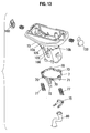
- the annular member 7 is positioned and fixed to the base portion 10 by a base 105 which projects from the small-diameter portion 10c and engages an inner side of the shaft portion 70, a groove 106 (see Fig. 13) into which the contact portion 72 is fitted and a lower end surface of the neck portion 10b.
- the contact portion 75 is formed as an independent part from the annular member 7.
- the motor 8 on the side of the head portion 1 and the circuit block 36 on the side of the main body grip portion 2 are connected to each other through a wire.
- a waterproof tube 80 renders this wire waterproof.
- the contact portion 75 also functions to fix an end of the waterproof tube 80 close to the head portion 1 to the base portion 10.
- the contact portion 75 is inserted into the small-diameter portion 10c from right side in Fig. 10, a hook on a tip end of the contact portion 75 engages the base portion 10, thereby sandwiching and fixing an end of the waterproof tube 80 between the base portion 10 and the contact portion 75.
- the end of the waterproof tube 80 closer to the circuit block 36 is sandwiched and fixed between a partition wall and a pressure plate 45 which is disposed on and fixed to the partition wall between the hermetic space 25 and the opened space 26.
- a rib 46 rises from the pressure plate 45.
- the waterproof tube 80 is led out from a lower end surface of the small-diameter portion 10c of the base portion 10 which is movable in the opened space 26.
- the rib 46 provides the waterproof tube 80 with necessary bending state.
- a window 210 brings the opened space 26 and an outer surface of the housing 21. A user can observe, through the window 210, the state of the waterproof tube 80 when the housings 21 and 22 are combined.
- the window 210 also functions to discharge water which enters the opened space 26.
- the head portion 1 can not only vertically move but also laterally tilt with respect to the main body grip portion 2. This is because, if the gap between an open edge 20 at an upper end opening of the main body grip portion 2 through which the head portion 1 is inserted and the neck portion 10b which is to be located on the inner peripheral side of the open edge 20 in the head portion 1 is not sufficiently large, the tilting motion of the head portion 1 is impaired. If the gap is excessively large, dusts such as shaved beard or moustache shavings are prone to enter the opened space 26 of the main body grip portion 2 from this gap.
- the left and right spring receivers 71 and 71 which are rotational axes A1 and A2 (see Fig. 7) of lateral tilting motion are located lower than the open edge 20.
- the neck portion 10b has a constant diameter, the gap becomes a maximum when the head portion 1 does not sink.
- the neck portion 10b is tapered from its lower side toward the upper side.
- the lower portion of the head portion is accommodated in the opened space of the main body grip portion.
- the neck portion is tapered from its lower side toward its upper side in the tilting direction.
- the neck portion is located at the opening of the main body grip portion. Therefore, the gap between the open edge of the main body grip portion and the neck portion of the head portion can be reduced in a state where the tiltable range of the head portion with respect to the main body grip portion is largely secured, and it is possible to lower the possibility that dusts such as shaved beard or moustache enter the main body grip portion from the gap to impair the motion of the head portion.
Landscapes
- Life Sciences & Earth Sciences (AREA)
- Forests & Forestry (AREA)
- Engineering & Computer Science (AREA)
- Mechanical Engineering (AREA)
- Dry Shavers And Clippers (AREA)
- Cosmetics (AREA)
Abstract
Description
- This application is based upon and claims the benefit of priority from a
Japanese Patent ApplicationNo. TOKUGAN 2005-160312, filed on May 31, 2005 - The present invention relates to a hair cutting device such as an electric shaver and a depilator for cutting hair.
- In a hair cutting device such as an electric shaver and a depilator, a head portion provided at its upper end surface with a blade head for cutting hair is supported by a main body grip portion such that the head portion can vertically float and can tilt, so that a contact pressure between the blade head and a skin is appropriately maintained and the blade head moves along the skin (
Japanese Patent Application Laid-open No. 2004-016527 - According to such a hair cutting device, when the head portion projects from an upper end opening of the main body grip portion, if a sufficient gap is not secured between an edge of the opening of the main body grip portion and a portion of the head portion which is located inside of the opening, the head portion cannot tilt.
- However, since the gap becomes a cause of ingress of shaved beard or moustache into the main body grip portion, it is desired to make the gap small while securing a large tilting range.
- The present invention has been achieved in view of the conventional problem, and it is an object of the invention to provide a hair cutting device capable of making a gap between a main body grip portion and a headportion small while largely securing a tilting range of a head portion with respect to the main body grip portion.
- To solve the above problem, the present invention provides a hair cutting device including a head portion provided at its upper end surface with a blade head for epilating hair, and a main body grip portion which supports the head portion in a manner that the head portion can vertically float and tilt, wherein a lower portion of the head portion is accommodated in an opened space formed in an upper portion of the main body grip portion, the head portion is supported in the opened space such that the motion is permitted, the head portion includes a neck portion whose lower side width in the tilting direction is wider than an upper side width, the neck portion is located at a portion of an opening formed in an upper end surface of the main body grip portion.
- With this configuration, it is possible to reduce the gap between the main body grip portion and the head portion while largely securing the tiltable range of the head portion with respect to the main body grip portion.
- It is preferable that a lower end of the head portion located lower than the neck portion has a width in the tilting direction smaller than the neck portion. The tiltable range of the headportion can be secured largely while suppressing the width of the main body grip portion.
- It is preferable that the head portion is supported such that the head portion can laterally tilt, an annular member is mounted on an outer surface of the head portion at a position lower than the neck portion, left and right two shaft portions respectively provided on a front surface and a back surface of the annular member are supported by a bearing formed on an inner surface of the opened space of the main body grip portion such that the shaft portions can turn and vertically move, and spring receivers provided on left and right ends of the annular member receive a push-up spring which biases the head portion upward. With this configuration, the head portion can be supported by the main body grip portion with a simple part configuration.
- Particularly, it is preferable that the annular member is made of a material that is different from those of a hull of the head portion and a hull of the main body grip portion, the annular member also functions as a slide guide member which comes into slide contact with an inner surface of the opened space of the main body grip portion and guides the motion of the head portion with respect to the main body grip portion. With this configuration, it becomes easy to support the head portion while suppressing unnecessary motion.
-
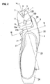
- Fig. 1 is a front view of one example of an embodiment of the present invention;
- Fig. 2 is a right side view of the example;
- Fig. 3 is a front view of a head portion of the example;
- Fig. 4 is a right side view of the head portion;
- Fig. 5 is a rear view of the head portion;
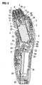
- Fig. 6 is a vertical sectional view (taken along the line A-A in Fig. 1) of the example;
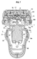
- Fig. 7 is a transverse sectional view (taken along the line B-B in Fig. 2) of the example;
- Fig. 8 is a horizontal sectional view (taken along the line C-C in Fig. 2) of the example;
- Fig. 9 is a rear view of a state where some parts of the example are removed;
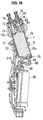
- Fig. 10 is a vertical sectional view (taken along the line D-D in Fig. 9) of a state where some parts of the example are removed;
- Fig. 11 is an exploded perspective view of a main body grip portion of the example;
- Fig. 12 is an exploded perspective view of the head portion of the example; and
- Fig. 13 is an exploded perspective view of a base portion of the head portion.
- The present invention is explained below based on embodiments shown in the accompanying drawings. A hair cutting device shown in the drawings is an electric shaver. The electric shaver includes a
head portion 1 and a mainbody grip portion 2. Thehead portion 1 is provided at its upper end surface with a plurality ofblade heads body grip portion 2 vertically movably and laterally tiltably supports thehead portion 1. As shown in Figs. 3 to 5 and 12, thehead portion 1 includes abase portion 10, aholding frame 11 which is detachably disposed on thebase portion 10, and amounting frame 12 which is detachable from and attachable to theholding frame 11. Theblade heads mounting frame 12. Areference numeral 100 represents a button for attaching and detaching theholding frame 11 provided on thebase portion 10, and areference numeral 120 represents a button provided on themounting frame 12 for attaching and detaching. - The
base portion 10 includes an upperwide portion 10a, a lower small-diameter portion 10c and aneck portion 10b located therebetween. An upper end opening of thebase portion 10 is closed with acover 13 shown in Fig. 12. Portions of twodrive elements wide portion 10a of thebase portion 10 are inserted through a central portion of thecover 13 and project upward. In Fig. 12, areference numeral 14 represents a waterproof rubber for making the inserting portion waterproof, and areference numeral 15 represents a fixing plate for fixing thewaterproof rubber 14. - The
drive elements wide portion 10a of thebase portion 10. Thedrive elements motor 8 accommodated in a small-diameter portion 10c througheccentric shafts Inner blades blade heads drive elements cover 13. A connectingelement 17 is connected to one of thedrive elements blade head 4. A connectingelement 18 is mounted on theother drive element 16 for driving a trimmer blade. Areference numeral 19 in Fig. 12 represents a blade protection cover. - As shown in Fig. 11, the main
body grip portion 2 includes longitudinally divided twohousings housings lower cover 24 which is put on lower ends of thehousings switch block 27 is disposed on a front surface of the mainbody grip portion 2, and atrimmer blade block 5 is located on a back surface of the mainbody grip portion 2. Thetrimmer blade block 5 is disposed on an outer surface of asupport piece 28 which rises from an upper portion of thehousing 22. If a lower handle portion is slid upward, an upper blade portion turns and projects. At that time, thetrimmer blade block 5 is connected to the connectingelement 18 and the reciprocating motion is transmitted. - An interior space of the main
body grip portion 2 is divided into an upper openedspace 26 and a lowerhermetic space 25. Asecondary battery 35 and acircuit block 36 shown in Fig. 6 are accommodated in thehermetic space 25 which is made waterproof by an O-ring 29. - The upper opened
space 26 of the mainbody grip portion 2 is a space in which the small-diameter portion 10c of thehead portion 1 is accommodated, and is a space which supports thehead portion 1 such that thehead portion 1 can vertically move and laterally tilt. Thehousings grooves shaft portions diameter portion 10c. Thehousing 21 is provided at its inner surface withspring receivers springs grooves shaft portions shaft portions - Upper ends of the push-up
springs spring receivers neck portion 10b of thehead portion 1. Therefore, thehead portion 1 is biased upward by the push-upsprings - If the
head portion 1 is pushed into the mainbody grip portion 2, thehead portion 1 sinks into the mainbody grip portion 2 against the biasing forces of the push-upsprings headportion 1 is pushed, theheadportion 1 is tilted around thespring receiver 71 located on the other side while compressing the one push-upspring 77. The reason why the width of the small-diameter portion 10c is smaller than theneck portion 10b is that the lateral tilting range of thehead portion 1 can be increased while reducing the width of the mainbody grip portion 2. - Portions of the
head portion 1 which come into contact with the mainbody grip portion 2 are limited to three portions of the front surface and three portions of the back surface of thehead portion 1 so as to make the above-describedmotion of thehead portion 1 smooth and not to generate rattle. The three portions of the back surface are the twoshafts diameter portion 10c and acontact portion 75 located on a lower end of a back surface of the small-diameter portion 10c. The three portions of the front surface are the twoshafts diameter portion 10c and acontact portion 72 located closer to a lower portion of the front surface of the small-diameter portion 10c. When thehead portion 1 vertically moves and tilts, these contact portions come into contact with the inner surfaces of thehousings - When members made of the same material slide against each other, they are worn abruptly. Therefore, such members are made of polyoxymethylene resin (Duracon) or the like, and an
annular member 7 mounted on thebase portion 10 of thehead portion 1 is provided with the fourshaft portions 71 andreceivers 72. Thecontact portion 75 is also made of polyoxymethylene resin (Duracon), and is mounted on a lower end of the back surface of the small-diameter portion 10c. - The
annular member 7 is integrally provided withspring receivers spring 77 in addition to the fourshaft portions 70 and thecontact portion 72 as described above. Theannular member 7 is mounted on thebase portion 10 from the small-diameter portion 10c utilizing resilience of theannular member 7 and margin caused by the gap generated between the portions of theannular member 7 which have thespring receivers diameter portion 10c. Theannular member 7 is positioned and fixed to thebase portion 10 by a base 105 which projects from the small-diameter portion 10c and engages an inner side of theshaft portion 70, a groove 106 (see Fig. 13) into which thecontact portion 72 is fitted and a lower end surface of theneck portion 10b. - The
contact portion 75 is formed as an independent part from theannular member 7. Themotor 8 on the side of thehead portion 1 and thecircuit block 36 on the side of the mainbody grip portion 2 are connected to each other through a wire. Awaterproof tube 80 renders this wire waterproof. Thecontact portion 75 also functions to fix an end of thewaterproof tube 80 close to thehead portion 1 to thebase portion 10. Thecontact portion 75 is inserted into the small-diameter portion 10c from right side in Fig. 10, a hook on a tip end of thecontact portion 75 engages thebase portion 10, thereby sandwiching and fixing an end of thewaterproof tube 80 between thebase portion 10 and thecontact portion 75. - The end of the
waterproof tube 80 closer to thecircuit block 36 is sandwiched and fixed between a partition wall and apressure plate 45 which is disposed on and fixed to the partition wall between thehermetic space 25 and the openedspace 26. Arib 46 rises from thepressure plate 45. Thewaterproof tube 80 is led out from a lower end surface of the small-diameter portion 10c of thebase portion 10 which is movable in the openedspace 26. Therib 46 provides thewaterproof tube 80 with necessary bending state. A window 210 (see Figs. 10 and 11) brings the openedspace 26 and an outer surface of thehousing 21. A user can observe, through thewindow 210, the state of thewaterproof tube 80 when thehousings window 210 also functions to discharge water which enters the openedspace 26. - The
head portion 1 can not only vertically move but also laterally tilt with respect to the mainbody grip portion 2. This is because, if the gap between anopen edge 20 at an upper end opening of the mainbody grip portion 2 through which thehead portion 1 is inserted and theneck portion 10b which is to be located on the inner peripheral side of theopen edge 20 in thehead portion 1 is not sufficiently large, the tilting motion of thehead portion 1 is impaired. If the gap is excessively large, dusts such as shaved beard or moustache shavings are prone to enter the openedspace 26 of the mainbody grip portion 2 from this gap. - For this end, the left and
right spring receivers open edge 20. In this configuration, if theneck portion 10b has a constant diameter, the gap becomes a maximum when thehead portion 1 does not sink. In view of this fact, theneck portion 10b is tapered from its lower side toward the upper side. With this configuration, when thehead portion 1 sinks straightly, the gap between theopen edge 20 and theneck portion 10b is increased, but there is no problem because the main motion of thehead portion 1 when a user grasps the mainbody grip portion 2 and pushes thehead portion 1 against her or his skin is to slightly tilt in left or right side. - The lower portion of the head portion is accommodated in the opened space of the main body grip portion. The neck portion is tapered from its lower side toward its upper side in the tilting direction. The neck portion is located at the opening of the main body grip portion. Therefore, the gap between the open edge of the main body grip portion and the neck portion of the head portion can be reduced in a state where the tiltable range of the head portion with respect to the main body grip portion is largely secured, and it is possible to lower the possibility that dusts such as shaved beard or moustache enter the main body grip portion from the gap to impair the motion of the head portion.
Claims (4)
- A hair cutting device comprising a head portion provided at its upper end surface with a blade head for epilating hair, and a main body grip portion which supports the head portion in a manner that the head portion can vertically float and tilt, wherein
a lower portion of the head portion is accommodated in an opened space formed in an upper portion of the main body grip portion, the head portion is supported in the opened space such that the motion is permitted, the head portion includes a neck portion whose lower side width in the tilting direction is wider than an upper side width, the neck portion is located at a portion of an opening formed in an upper end surface of the main body grip portion. - The hair cutting device according to claim 1, wherein a lower end of the head portion located lower than the neck portion has a width in the tilting direction smaller than the neck portion.
- The hair cutting device according to claim 1 or 2, wherein the headportion is supported such that the headportion can laterally tilt, an annular member is mounted on an outer surface of the head portion at a position lower than the neck portion, left and right two shaft portions respectively provided on a front surface and a back surface of the annular member are supported by a bearing formed on an inner surface of the opened space of the main body grip portion such that the shaft portions can turn and vertically move, and spring receivers provided on left and right ends of the annular member receive a push-up spring which biases the head portion upward.
- The hair cutting device according to claim 3, wherein the annular member is made of a material that is different from those of a hull of the head portion and a hull of the main body grip portion, the annular member also functions as a slide guide member which comes into slide contact with an inner surface of the opened space of the main body grip portion and guides the motion of the head portion with respect to the main body grip portion.
Applications Claiming Priority (1)
| Application Number | Priority Date | Filing Date | Title |
|---|---|---|---|
| JP2005160312A JP4604846B2 (en) | 2005-05-31 | 2005-05-31 | Hair treatment equipment |
Publications (2)
| Publication Number | Publication Date |
|---|---|
| EP1728603A1 true EP1728603A1 (en) | 2006-12-06 |
| EP1728603B1 EP1728603B1 (en) | 2008-03-26 |
Family
ID=36926320
Family Applications (1)
| Application Number | Title | Priority Date | Filing Date |
|---|---|---|---|
| EP06011286A Not-in-force EP1728603B1 (en) | 2005-05-31 | 2006-05-31 | Hair cutting device |
Country Status (7)
| Country | Link |
|---|---|
| US (1) | US8181349B2 (en) |
| EP (1) | EP1728603B1 (en) |
| JP (1) | JP4604846B2 (en) |
| KR (1) | KR100768992B1 (en) |
| CN (2) | CN100519110C (en) |
| AT (1) | ATE390254T1 (en) |
| DE (1) | DE602006000789T2 (en) |
Cited By (1)
| Publication number | Priority date | Publication date | Assignee | Title |
|---|---|---|---|---|
| EP2243604A3 (en) * | 2009-04-23 | 2010-12-22 | Izumi Products Company | Reciprocating electric shaver |
Families Citing this family (26)
| Publication number | Priority date | Publication date | Assignee | Title |
|---|---|---|---|---|
| DE102006034050A1 (en) * | 2006-07-20 | 2008-01-24 | Braun Gmbh | Electric shaver |
| JP4285564B2 (en) * | 2007-06-27 | 2009-06-24 | パナソニック電工株式会社 | Hair removal equipment |
| JP4730353B2 (en) * | 2007-08-28 | 2011-07-20 | パナソニック電工株式会社 | Clippers |
| CN101549499B (en) * | 2008-03-31 | 2013-03-13 | 超人集团有限公司 | Rotary type shaver with head part capable of omnidirectionally floating |
| JP4988777B2 (en) * | 2009-01-15 | 2012-08-01 | パナソニック株式会社 | Electric razor |
| JP4955711B2 (en) | 2009-01-15 | 2012-06-20 | パナソニック株式会社 | Electric razor |
| US9027252B2 (en) * | 2010-03-19 | 2015-05-12 | Wahl Clipper Corporation | Low resistance hair clipper blade tooth profile |
| CN101890730A (en) * | 2010-07-09 | 2010-11-24 | 美的集团有限公司 | Omnibearing floating rotary shaver |
| JP5820995B2 (en) * | 2011-07-28 | 2015-11-24 | パナソニックIpマネジメント株式会社 | Blade protection cap and electric razor to which the blade protection cap is attached |
| JP5959348B2 (en) * | 2012-07-18 | 2016-08-02 | 日立マクセル株式会社 | Electric razor |
| JP6376468B2 (en) * | 2014-11-28 | 2018-08-22 | パナソニックIpマネジメント株式会社 | Electric razor |
| USD765914S1 (en) | 2015-01-06 | 2016-09-06 | Telebrands Corp. | Abrasive skin treatment device |
| US10004535B2 (en) | 2016-01-27 | 2018-06-26 | Telebrands Corp. | Abrasive skin treatment device |
| EP3300844B1 (en) | 2016-09-28 | 2020-04-15 | Braun GmbH | Electric shaver |
| EP3300861B1 (en) | 2016-09-28 | 2019-07-03 | Braun GmbH | Electrically driven device |
| CN106963460B (en) * | 2017-05-23 | 2023-07-21 | 深圳价之链跨境电商有限公司 | Skin cleaning device and application method thereof |
| EP3689180B1 (en) * | 2017-10-06 | 2021-11-03 | Braun GmbH | Epilator |
| CN110267779B (en) * | 2018-11-23 | 2021-09-03 | 浙江夏隆电器有限公司 | Shaver with a handle |
| CN109519629B (en) * | 2018-12-10 | 2021-02-02 | 上海蔚来汽车有限公司 | Floating fluid connection plug, socket, and connector and cooling system comprising same |
| EP3907048B1 (en) * | 2020-05-08 | 2023-03-22 | Braun GmbH | Electric beard trimmer |
| EP3907044A1 (en) | 2020-05-08 | 2021-11-10 | Braun GmbH | Electric beard trimmer |
| EP3907049B1 (en) | 2020-05-08 | 2023-03-22 | Braun GmbH | Electric beard trimmer |
| USD1022327S1 (en) | 2020-12-23 | 2024-04-09 | International Edge, Inc. | Foot file |
| USD1017136S1 (en) | 2020-12-23 | 2024-03-05 | Telebrands Corp. | Abrasive skin treatment device |
| USD1005504S1 (en) | 2020-12-23 | 2023-11-21 | Telebrands Corp. | Abrasive skin treatment device |
| USD1023468S1 (en) | 2021-03-29 | 2024-04-16 | Telebrands Corp. | Foot file |
Citations (5)
| Publication number | Priority date | Publication date | Assignee | Title |
|---|---|---|---|---|
| GB2266070A (en) * | 1992-04-10 | 1993-10-20 | Gillette Co | Dry shaver |
| JP2004016527A (en) | 2002-06-17 | 2004-01-22 | Matsushita Electric Works Ltd | Electric razor |
| EP1404494B1 (en) * | 2002-06-17 | 2004-10-06 | Matsushita Electric Works, Ltd. | Dry shaver with a trimmer |
| US20050016002A1 (en) * | 2003-07-22 | 2005-01-27 | Matsushita Electric Works, Ltd., | Electric shaver |
| JP2005160312A (en) | 2003-11-28 | 2005-06-23 | Nichirei Corp | Coating liquid for deep fry, deep fry and method for producing the deep fry |
Family Cites Families (10)
| Publication number | Priority date | Publication date | Assignee | Title |
|---|---|---|---|---|
| AT337572B (en) * | 1975-07-28 | 1977-07-11 | Philips Nv | ELECTRIC MOTOR DRIVEN DEVICE |
| NL8600154A (en) * | 1986-01-24 | 1987-08-17 | Philips Nv | SHAVER. |
| US6317982B1 (en) * | 1999-10-22 | 2001-11-20 | Remington Corporation L.L.C. | Shaving system and adjustable trimmers therefor |
| JP4868480B2 (en) * | 2001-04-27 | 2012-02-01 | 九州日立マクセル株式会社 | Electric razor |
| JP4030741B2 (en) | 2001-10-18 | 2008-01-09 | 九州日立マクセル株式会社 | Electric razor |
| ATE303886T1 (en) | 2001-11-15 | 2005-09-15 | Matsushita Electric Works Ltd | DRY RAZOR WITH SWIVELING HEAD |
| KR100563481B1 (en) * | 2002-06-17 | 2006-03-27 | 마츠시다 덴코 가부시키가이샤 | Electric Shaver Floating Head Support Structure |
| JP3972903B2 (en) * | 2003-12-26 | 2007-09-05 | 松下電工株式会社 | Electric razor |
| JP2006042898A (en) * | 2004-07-30 | 2006-02-16 | Matsushita Electric Works Ltd | Electric shaver |
| JP4725103B2 (en) * | 2004-12-28 | 2011-07-13 | パナソニック電工株式会社 | Reciprocating electric razor |
-
2005
- 2005-05-31 JP JP2005160312A patent/JP4604846B2/en active Active
-
2006
- 2006-05-30 KR KR1020060048422A patent/KR100768992B1/en not_active IP Right Cessation
- 2006-05-30 US US11/420,899 patent/US8181349B2/en active Active
- 2006-05-31 EP EP06011286A patent/EP1728603B1/en not_active Not-in-force
- 2006-05-31 DE DE602006000789T patent/DE602006000789T2/en active Active
- 2006-05-31 CN CNB2006100899925A patent/CN100519110C/en active Active
- 2006-05-31 AT AT06011286T patent/ATE390254T1/en not_active IP Right Cessation
- 2006-05-31 CN CNU2006201164546U patent/CN2908078Y/en not_active Expired - Fee Related
Patent Citations (5)
| Publication number | Priority date | Publication date | Assignee | Title |
|---|---|---|---|---|
| GB2266070A (en) * | 1992-04-10 | 1993-10-20 | Gillette Co | Dry shaver |
| JP2004016527A (en) | 2002-06-17 | 2004-01-22 | Matsushita Electric Works Ltd | Electric razor |
| EP1404494B1 (en) * | 2002-06-17 | 2004-10-06 | Matsushita Electric Works, Ltd. | Dry shaver with a trimmer |
| US20050016002A1 (en) * | 2003-07-22 | 2005-01-27 | Matsushita Electric Works, Ltd., | Electric shaver |
| JP2005160312A (en) | 2003-11-28 | 2005-06-23 | Nichirei Corp | Coating liquid for deep fry, deep fry and method for producing the deep fry |
Cited By (2)
| Publication number | Priority date | Publication date | Assignee | Title |
|---|---|---|---|---|
| EP2243604A3 (en) * | 2009-04-23 | 2010-12-22 | Izumi Products Company | Reciprocating electric shaver |
| US8720069B2 (en) | 2009-04-23 | 2014-05-13 | Izumi Products Company | Reciprocating electric shaver |
Also Published As
| Publication number | Publication date |
|---|---|
| JP4604846B2 (en) | 2011-01-05 |
| CN100519110C (en) | 2009-07-29 |
| CN2908078Y (en) | 2007-06-06 |
| CN1872504A (en) | 2006-12-06 |
| ATE390254T1 (en) | 2008-04-15 |
| DE602006000789D1 (en) | 2008-05-08 |
| US20060265879A1 (en) | 2006-11-30 |
| KR20060125507A (en) | 2006-12-06 |
| KR100768992B1 (en) | 2007-10-22 |
| US8181349B2 (en) | 2012-05-22 |
| DE602006000789T2 (en) | 2009-04-09 |
| EP1728603B1 (en) | 2008-03-26 |
| JP2006333998A (en) | 2006-12-14 |
Similar Documents
| Publication | Publication Date | Title |
|---|---|---|
| EP1728603B1 (en) | Hair cutting device | |
| EP1728602B1 (en) | Hair cutting device | |
| JP4552646B2 (en) | Hair removal equipment | |
| JP4103873B2 (en) | Comb vibration prevention structure of hair cutter | |
| CA2393851C (en) | Attachment for hair clippers | |
| KR100562388B1 (en) | Dry shaver with a cradle shaving head | |
| US20100018057A1 (en) | Electric shaver | |
| KR200396688Y1 (en) | Slim type razor | |
| JP2017148645A (en) | Wet shaving razor | |
| US7690117B2 (en) | Shaving apparatus with a short-hair cutting device and a long-hair cutting device | |
| EP2492066B1 (en) | Electric shaver | |
| ATE341200T1 (en) | SWIVELING HANDLE ARRANGEMENT FOR A POWER TOOL | |
| JP5897421B2 (en) | Electric razor | |
| JP4573260B2 (en) | Electric razor | |
| US10220530B2 (en) | Electric shaver | |
| JP4888882B2 (en) | Clippers | |
| JP2000288267A (en) | Electric razor | |
| CN218428462U (en) | Cutting and shaving device | |
| JP3861796B2 (en) | Electric razor movable head holding structure | |
| JP3493701B2 (en) | Reciprocating electric razor | |
| JPH0639153A (en) | Electric razor |
Legal Events
| Date | Code | Title | Description |
|---|---|---|---|
| PUAI | Public reference made under article 153(3) epc to a published international application that has entered the european phase |
Free format text: ORIGINAL CODE: 0009012 |
|
| 17P | Request for examination filed |
Effective date: 20060531 |
|
| AK | Designated contracting states |
Kind code of ref document: A1 Designated state(s): AT BE BG CH CY CZ DE DK EE ES FI FR GB GR HU IE IS IT LI LT LU LV MC NL PL PT RO SE SI SK TR |
|
| AX | Request for extension of the european patent |
Extension state: AL BA HR MK YU |
|
| AKX | Designation fees paid |
Designated state(s): AT BE BG CH CY CZ DE DK EE ES FI FR GB GR HU IE IS IT LI LT LU LV MC NL PL PT RO SE SI SK TR |
|
| GRAC | Information related to communication of intention to grant a patent modified |
Free format text: ORIGINAL CODE: EPIDOSCIGR1 |
|
| GRAP | Despatch of communication of intention to grant a patent |
Free format text: ORIGINAL CODE: EPIDOSNIGR1 |
|
| GRAS | Grant fee paid |
Free format text: ORIGINAL CODE: EPIDOSNIGR3 |
|
| GRAA | (expected) grant |
Free format text: ORIGINAL CODE: 0009210 |
|
| AK | Designated contracting states |
Kind code of ref document: B1 Designated state(s): AT BE BG CH CY CZ DE DK EE ES FI FR GB GR HU IE IS IT LI LT LU LV MC NL PL PT RO SE SI SK TR |
|
| REG | Reference to a national code |
Ref country code: GB Ref legal event code: FG4D |
|
| REG | Reference to a national code |
Ref country code: CH Ref legal event code: EP Ref country code: IE Ref legal event code: FG4D |
|
| REF | Corresponds to: |
Ref document number: 602006000789 Country of ref document: DE Date of ref document: 20080508 Kind code of ref document: P |
|
| PG25 | Lapsed in a contracting state [announced via postgrant information from national office to epo] |
Ref country code: FI Free format text: LAPSE BECAUSE OF FAILURE TO SUBMIT A TRANSLATION OF THE DESCRIPTION OR TO PAY THE FEE WITHIN THE PRESCRIBED TIME-LIMIT Effective date: 20080326 |
|
| PG25 | Lapsed in a contracting state [announced via postgrant information from national office to epo] |
Ref country code: AT Free format text: LAPSE BECAUSE OF FAILURE TO SUBMIT A TRANSLATION OF THE DESCRIPTION OR TO PAY THE FEE WITHIN THE PRESCRIBED TIME-LIMIT Effective date: 20080326 |
|
| NLV1 | Nl: lapsed or annulled due to failure to fulfill the requirements of art. 29p and 29m of the patents act | ||
| PG25 | Lapsed in a contracting state [announced via postgrant information from national office to epo] |
Ref country code: SI Free format text: LAPSE BECAUSE OF FAILURE TO SUBMIT A TRANSLATION OF THE DESCRIPTION OR TO PAY THE FEE WITHIN THE PRESCRIBED TIME-LIMIT Effective date: 20080326 Ref country code: LV Free format text: LAPSE BECAUSE OF FAILURE TO SUBMIT A TRANSLATION OF THE DESCRIPTION OR TO PAY THE FEE WITHIN THE PRESCRIBED TIME-LIMIT Effective date: 20080326 Ref country code: PL Free format text: LAPSE BECAUSE OF FAILURE TO SUBMIT A TRANSLATION OF THE DESCRIPTION OR TO PAY THE FEE WITHIN THE PRESCRIBED TIME-LIMIT Effective date: 20080326 Ref country code: BE Free format text: LAPSE BECAUSE OF FAILURE TO SUBMIT A TRANSLATION OF THE DESCRIPTION OR TO PAY THE FEE WITHIN THE PRESCRIBED TIME-LIMIT Effective date: 20080326 |
|
| PG25 | Lapsed in a contracting state [announced via postgrant information from national office to epo] |
Ref country code: CZ Free format text: LAPSE BECAUSE OF FAILURE TO SUBMIT A TRANSLATION OF THE DESCRIPTION OR TO PAY THE FEE WITHIN THE PRESCRIBED TIME-LIMIT Effective date: 20080326 Ref country code: SK Free format text: LAPSE BECAUSE OF FAILURE TO SUBMIT A TRANSLATION OF THE DESCRIPTION OR TO PAY THE FEE WITHIN THE PRESCRIBED TIME-LIMIT Effective date: 20080326 Ref country code: ES Free format text: LAPSE BECAUSE OF FAILURE TO SUBMIT A TRANSLATION OF THE DESCRIPTION OR TO PAY THE FEE WITHIN THE PRESCRIBED TIME-LIMIT Effective date: 20080707 Ref country code: PT Free format text: LAPSE BECAUSE OF FAILURE TO SUBMIT A TRANSLATION OF THE DESCRIPTION OR TO PAY THE FEE WITHIN THE PRESCRIBED TIME-LIMIT Effective date: 20080901 Ref country code: SE Free format text: LAPSE BECAUSE OF FAILURE TO SUBMIT A TRANSLATION OF THE DESCRIPTION OR TO PAY THE FEE WITHIN THE PRESCRIBED TIME-LIMIT Effective date: 20080626 |
|
| PG25 | Lapsed in a contracting state [announced via postgrant information from national office to epo] |
Ref country code: NL Free format text: LAPSE BECAUSE OF FAILURE TO SUBMIT A TRANSLATION OF THE DESCRIPTION OR TO PAY THE FEE WITHIN THE PRESCRIBED TIME-LIMIT Effective date: 20080326 Ref country code: RO Free format text: LAPSE BECAUSE OF FAILURE TO SUBMIT A TRANSLATION OF THE DESCRIPTION OR TO PAY THE FEE WITHIN THE PRESCRIBED TIME-LIMIT Effective date: 20080326 |
|
| PG25 | Lapsed in a contracting state [announced via postgrant information from national office to epo] |
Ref country code: IS Free format text: LAPSE BECAUSE OF FAILURE TO SUBMIT A TRANSLATION OF THE DESCRIPTION OR TO PAY THE FEE WITHIN THE PRESCRIBED TIME-LIMIT Effective date: 20080726 Ref country code: MC Free format text: LAPSE BECAUSE OF NON-PAYMENT OF DUE FEES Effective date: 20080531 |
|
| EN | Fr: translation not filed | ||
| PG25 | Lapsed in a contracting state [announced via postgrant information from national office to epo] |
Ref country code: DK Free format text: LAPSE BECAUSE OF FAILURE TO SUBMIT A TRANSLATION OF THE DESCRIPTION OR TO PAY THE FEE WITHIN THE PRESCRIBED TIME-LIMIT Effective date: 20080326 Ref country code: LT Free format text: LAPSE BECAUSE OF FAILURE TO SUBMIT A TRANSLATION OF THE DESCRIPTION OR TO PAY THE FEE WITHIN THE PRESCRIBED TIME-LIMIT Effective date: 20080326 |
|
| PLBE | No opposition filed within time limit |
Free format text: ORIGINAL CODE: 0009261 |
|
| STAA | Information on the status of an ep patent application or granted ep patent |
Free format text: STATUS: NO OPPOSITION FILED WITHIN TIME LIMIT |
|
| 26N | No opposition filed |
Effective date: 20081230 |
|
| PG25 | Lapsed in a contracting state [announced via postgrant information from national office to epo] |
Ref country code: IE Free format text: LAPSE BECAUSE OF NON-PAYMENT OF DUE FEES Effective date: 20080603 Ref country code: EE Free format text: LAPSE BECAUSE OF FAILURE TO SUBMIT A TRANSLATION OF THE DESCRIPTION OR TO PAY THE FEE WITHIN THE PRESCRIBED TIME-LIMIT Effective date: 20080326 Ref country code: BG Free format text: LAPSE BECAUSE OF FAILURE TO SUBMIT A TRANSLATION OF THE DESCRIPTION OR TO PAY THE FEE WITHIN THE PRESCRIBED TIME-LIMIT Effective date: 20080626 Ref country code: FR Free format text: LAPSE BECAUSE OF FAILURE TO SUBMIT A TRANSLATION OF THE DESCRIPTION OR TO PAY THE FEE WITHIN THE PRESCRIBED TIME-LIMIT Effective date: 20090116 |
|
| PG25 | Lapsed in a contracting state [announced via postgrant information from national office to epo] |
Ref country code: IT Free format text: LAPSE BECAUSE OF FAILURE TO SUBMIT A TRANSLATION OF THE DESCRIPTION OR TO PAY THE FEE WITHIN THE PRESCRIBED TIME-LIMIT Effective date: 20080326 |
|
| PG25 | Lapsed in a contracting state [announced via postgrant information from national office to epo] |
Ref country code: CY Free format text: LAPSE BECAUSE OF FAILURE TO SUBMIT A TRANSLATION OF THE DESCRIPTION OR TO PAY THE FEE WITHIN THE PRESCRIBED TIME-LIMIT Effective date: 20080326 |
|
| PG25 | Lapsed in a contracting state [announced via postgrant information from national office to epo] |
Ref country code: HU Free format text: LAPSE BECAUSE OF FAILURE TO SUBMIT A TRANSLATION OF THE DESCRIPTION OR TO PAY THE FEE WITHIN THE PRESCRIBED TIME-LIMIT Effective date: 20080927 Ref country code: LU Free format text: LAPSE BECAUSE OF NON-PAYMENT OF DUE FEES Effective date: 20080531 |
|
| PG25 | Lapsed in a contracting state [announced via postgrant information from national office to epo] |
Ref country code: TR Free format text: LAPSE BECAUSE OF FAILURE TO SUBMIT A TRANSLATION OF THE DESCRIPTION OR TO PAY THE FEE WITHIN THE PRESCRIBED TIME-LIMIT Effective date: 20080326 |
|
| PG25 | Lapsed in a contracting state [announced via postgrant information from national office to epo] |
Ref country code: GR Free format text: LAPSE BECAUSE OF FAILURE TO SUBMIT A TRANSLATION OF THE DESCRIPTION OR TO PAY THE FEE WITHIN THE PRESCRIBED TIME-LIMIT Effective date: 20080627 |
|
| REG | Reference to a national code |
Ref country code: CH Ref legal event code: PL |
|
| GBPC | Gb: european patent ceased through non-payment of renewal fee |
Effective date: 20100531 |
|
| PG25 | Lapsed in a contracting state [announced via postgrant information from national office to epo] |
Ref country code: CH Free format text: LAPSE BECAUSE OF NON-PAYMENT OF DUE FEES Effective date: 20100531 Ref country code: LI Free format text: LAPSE BECAUSE OF NON-PAYMENT OF DUE FEES Effective date: 20100531 |
|
| PG25 | Lapsed in a contracting state [announced via postgrant information from national office to epo] |
Ref country code: GB Free format text: LAPSE BECAUSE OF NON-PAYMENT OF DUE FEES Effective date: 20100531 |
|
| PGFP | Annual fee paid to national office [announced via postgrant information from national office to epo] |
Ref country code: DE Payment date: 20220308 Year of fee payment: 17 |
|
| REG | Reference to a national code |
Ref country code: DE Ref legal event code: R119 Ref document number: 602006000789 Country of ref document: DE |
|
| PG25 | Lapsed in a contracting state [announced via postgrant information from national office to epo] |
Ref country code: DE Free format text: LAPSE BECAUSE OF NON-PAYMENT OF DUE FEES Effective date: 20231201 |