EP1720505B1 - Compression apparatus - Google Patents
Compression apparatus Download PDFInfo
- Publication number
- EP1720505B1 EP1720505B1 EP05723526A EP05723526A EP1720505B1 EP 1720505 B1 EP1720505 B1 EP 1720505B1 EP 05723526 A EP05723526 A EP 05723526A EP 05723526 A EP05723526 A EP 05723526A EP 1720505 B1 EP1720505 B1 EP 1720505B1
- Authority
- EP
- European Patent Office
- Prior art keywords
- foot
- layer
- strap
- sleeve
- compression apparatus
- Prior art date
- Legal status (The legal status is an assumption and is not a legal conclusion. Google has not performed a legal analysis and makes no representation as to the accuracy of the status listed.)
- Not-in-force
Links
Images


Classifications
-
- A—HUMAN NECESSITIES
- A61—MEDICAL OR VETERINARY SCIENCE; HYGIENE
- A61H—PHYSICAL THERAPY APPARATUS, e.g. DEVICES FOR LOCATING OR STIMULATING REFLEX POINTS IN THE BODY; ARTIFICIAL RESPIRATION; MASSAGE; BATHING DEVICES FOR SPECIAL THERAPEUTIC OR HYGIENIC PURPOSES OR SPECIFIC PARTS OF THE BODY
- A61H23/00—Percussion or vibration massage, e.g. using supersonic vibration; Suction-vibration massage; Massage with moving diaphragms
- A61H23/04—Percussion or vibration massage, e.g. using supersonic vibration; Suction-vibration massage; Massage with moving diaphragms with hydraulic or pneumatic drive
-
- A—HUMAN NECESSITIES
- A61—MEDICAL OR VETERINARY SCIENCE; HYGIENE
- A61H—PHYSICAL THERAPY APPARATUS, e.g. DEVICES FOR LOCATING OR STIMULATING REFLEX POINTS IN THE BODY; ARTIFICIAL RESPIRATION; MASSAGE; BATHING DEVICES FOR SPECIAL THERAPEUTIC OR HYGIENIC PURPOSES OR SPECIFIC PARTS OF THE BODY
- A61H9/00—Pneumatic or hydraulic massage
- A61H9/005—Pneumatic massage
- A61H9/0078—Pneumatic massage with intermittent or alternately inflated bladders or cuffs
-
- A—HUMAN NECESSITIES
- A61—MEDICAL OR VETERINARY SCIENCE; HYGIENE
- A61H—PHYSICAL THERAPY APPARATUS, e.g. DEVICES FOR LOCATING OR STIMULATING REFLEX POINTS IN THE BODY; ARTIFICIAL RESPIRATION; MASSAGE; BATHING DEVICES FOR SPECIAL THERAPEUTIC OR HYGIENIC PURPOSES OR SPECIFIC PARTS OF THE BODY
- A61H2201/00—Characteristics of apparatus not provided for in the preceding codes
- A61H2201/16—Physical interface with patient
- A61H2201/1602—Physical interface with patient kind of interface, e.g. head rest, knee support or lumbar support
- A61H2201/1645—Physical interface with patient kind of interface, e.g. head rest, knee support or lumbar support contoured to fit the user
-
- A—HUMAN NECESSITIES
- A61—MEDICAL OR VETERINARY SCIENCE; HYGIENE
- A61H—PHYSICAL THERAPY APPARATUS, e.g. DEVICES FOR LOCATING OR STIMULATING REFLEX POINTS IN THE BODY; ARTIFICIAL RESPIRATION; MASSAGE; BATHING DEVICES FOR SPECIAL THERAPEUTIC OR HYGIENIC PURPOSES OR SPECIFIC PARTS OF THE BODY
- A61H2201/00—Characteristics of apparatus not provided for in the preceding codes
- A61H2201/16—Physical interface with patient
- A61H2201/1683—Surface of interface
- A61H2201/169—Physical characteristics of the surface, e.g. material, relief, texture or indicia
- A61H2201/1697—Breathability of the material
-
- A—HUMAN NECESSITIES
- A61—MEDICAL OR VETERINARY SCIENCE; HYGIENE
- A61H—PHYSICAL THERAPY APPARATUS, e.g. DEVICES FOR LOCATING OR STIMULATING REFLEX POINTS IN THE BODY; ARTIFICIAL RESPIRATION; MASSAGE; BATHING DEVICES FOR SPECIAL THERAPEUTIC OR HYGIENIC PURPOSES OR SPECIFIC PARTS OF THE BODY
- A61H2201/00—Characteristics of apparatus not provided for in the preceding codes
- A61H2201/50—Control means thereof
- A61H2201/5002—Means for controlling a set of similar massage devices acting in sequence at different locations on a patient
-
- A—HUMAN NECESSITIES
- A61—MEDICAL OR VETERINARY SCIENCE; HYGIENE
- A61H—PHYSICAL THERAPY APPARATUS, e.g. DEVICES FOR LOCATING OR STIMULATING REFLEX POINTS IN THE BODY; ARTIFICIAL RESPIRATION; MASSAGE; BATHING DEVICES FOR SPECIAL THERAPEUTIC OR HYGIENIC PURPOSES OR SPECIFIC PARTS OF THE BODY
- A61H2201/00—Characteristics of apparatus not provided for in the preceding codes
- A61H2201/50—Control means thereof
- A61H2201/5007—Control means thereof computer controlled
-
- A—HUMAN NECESSITIES
- A61—MEDICAL OR VETERINARY SCIENCE; HYGIENE
- A61H—PHYSICAL THERAPY APPARATUS, e.g. DEVICES FOR LOCATING OR STIMULATING REFLEX POINTS IN THE BODY; ARTIFICIAL RESPIRATION; MASSAGE; BATHING DEVICES FOR SPECIAL THERAPEUTIC OR HYGIENIC PURPOSES OR SPECIFIC PARTS OF THE BODY
- A61H2201/00—Characteristics of apparatus not provided for in the preceding codes
- A61H2201/50—Control means thereof
- A61H2201/5058—Sensors or detectors
- A61H2201/5071—Pressure sensors
-
- A—HUMAN NECESSITIES
- A61—MEDICAL OR VETERINARY SCIENCE; HYGIENE
- A61H—PHYSICAL THERAPY APPARATUS, e.g. DEVICES FOR LOCATING OR STIMULATING REFLEX POINTS IN THE BODY; ARTIFICIAL RESPIRATION; MASSAGE; BATHING DEVICES FOR SPECIAL THERAPEUTIC OR HYGIENIC PURPOSES OR SPECIFIC PARTS OF THE BODY
- A61H2205/00—Devices for specific parts of the body
- A61H2205/06—Arms
-
- A—HUMAN NECESSITIES
- A61—MEDICAL OR VETERINARY SCIENCE; HYGIENE
- A61H—PHYSICAL THERAPY APPARATUS, e.g. DEVICES FOR LOCATING OR STIMULATING REFLEX POINTS IN THE BODY; ARTIFICIAL RESPIRATION; MASSAGE; BATHING DEVICES FOR SPECIAL THERAPEUTIC OR HYGIENIC PURPOSES OR SPECIFIC PARTS OF THE BODY
- A61H2205/00—Devices for specific parts of the body
- A61H2205/10—Leg
-
- A—HUMAN NECESSITIES
- A61—MEDICAL OR VETERINARY SCIENCE; HYGIENE
- A61H—PHYSICAL THERAPY APPARATUS, e.g. DEVICES FOR LOCATING OR STIMULATING REFLEX POINTS IN THE BODY; ARTIFICIAL RESPIRATION; MASSAGE; BATHING DEVICES FOR SPECIAL THERAPEUTIC OR HYGIENIC PURPOSES OR SPECIFIC PARTS OF THE BODY
- A61H2205/00—Devices for specific parts of the body
- A61H2205/12—Feet
-
- A—HUMAN NECESSITIES
- A61—MEDICAL OR VETERINARY SCIENCE; HYGIENE
- A61H—PHYSICAL THERAPY APPARATUS, e.g. DEVICES FOR LOCATING OR STIMULATING REFLEX POINTS IN THE BODY; ARTIFICIAL RESPIRATION; MASSAGE; BATHING DEVICES FOR SPECIAL THERAPEUTIC OR HYGIENIC PURPOSES OR SPECIFIC PARTS OF THE BODY
- A61H2209/00—Devices for avoiding blood stagnation, e.g. Deep Vein Thrombosis [DVT] devices
Definitions
- the present disclosure generally relates to the field of vascular therapy for application to a limb of a body, and more particularly, to a compression apparatus configured to artificially stimulate blood vessels of the limb.
- a major concern for immobile patients and persons alike are medical conditions that form clots in the blood, such as, deep vein thrombosis (DVT) and peripheral edema.
- DVT deep vein thrombosis
- Such patients and persons include those undergoing surgery, anesthesia and extended periods of bed rest.
- These blood clotting conditions generally occur in the deep veins of the lower extremities and/or pelvis.
- These veins such as the iliac, femoral, popiteal and tibial return deoxygenated to the heart.
- a static pool of blood is ideal for clot formations.
- a major risk associated with this condition is interference with cardiovascular circulation. Most seriously, a fragment of the blood clot can break loose and migrate.
- a pulmonary emboli can form blocking a main pulmonary artery, which may be life threatening.
- the conditions and resulting risks associated with patient immobility may be controlled or alleviated by applying intermittent pressure to a patient's limb, such as, for example, portions of a leg and foot to assist in blood circulation.
- a patient's limb such as, for example, portions of a leg and foot to assist in blood circulation.
- Known devices have been employed to assist in blood circulation, such as, one piece pads and compression boots. See, for example, U.S. Patent Nos. 4,696,289 and 5,989,204 .
- Compression devices that consist of an air pump connected to a disposable wraparound pad by one or more air tubes have been used.
- the wraparound pad is placed around the patient's foot or other extremity. Air is then forced into the wraparound pad creating pressure around the parts of the foot or other extremity.
- An apparatus according to the preamble of claim 1 is known from US-A-5 354 260 .
- a compression apparatus including the foot sleeve reduces bulk and is not cumbersome during use to improve comfort and compliance to a patient. It is further contemplated that the compression apparatus is easily and efficiently manufactured.
- the present invention provides an apparatus according to claim 1.
- a compression apparatus that prevents contamination, mitigates the incidence of skin breakdown and facilitates disposal with an extremity for overcoming the disadvantages and drawbacks of the prior art.
- a compression apparatus including the foot sleeve reduces bulk and is not cumbersome during use to improve comfort and compliance to a patient.
- the compression apparatus is easily and efficiently fabricated.
- the embodiments of the compression apparatus are configured to provide vascular therapy, including for example the prevention of deep vein thrombosis ("DVT") by artificially stimulating blood vessels throughout the foot of a patient, including the toes and the heel, to increase blood circulation for patients.
- the compression apparatus according to the present disclosure is an intermittent pneumatic compression device for applying slow compression to a foot. Such pressure simulates blood flow that would normally result from, for example, walking, by employing a foot sleeve that is supported about a foot of a patient.
- the compression apparatus may have an inflatable bladder designed to cover and engage the entire area of the bottom of the foot, beyond the heel and ball to a substantial portion of the toes.
- the inflatable bladder wraps about the side portions of the foot via a hook and loop type connector flap that transverses the instep of the foot.
- the inflatable bladder includes an outside layer and an inside layer.
- the bladder can be formed by welding the outside layer and the inside layer together.
- the bladder provides a uniform application of pressure to the entire foot and is then deflated.
- the compression apparatus may include bladder sections that are capable of enabling venous refill detection.
- the compression apparatus according to the present disclosure includes various embodiments and combinations as will be appreciated herein. The various embodiments and combinations may each be manufactured in various sizes to accommodate subjects of varying sizes as well as right and left foot models.
- the compression apparatus includes a strap.
- the strap is integrated with a foot sleeve by sandwiching the strap between separate layers of the foot sleeve body.
- the comfort to the patient may be improved by segmenting the strap to contour about the heel of the foot.
- the strap includes layers configured to provide a barrier to the cushioning layer from the environment.
- the foot sleeve can improve ease of use by having a universal design with a one flap metatarsal closure.
- the strap includes a laminate consisting of various layers.
- the layers include a center layer that is configured for comfort. Outside layers disposed about the center layer provide a barrier between the environment and an outer surface of the foot. One of the outside layers can be a skin contact layer that is soft to the touch.
- the strap is a separate part integrated into the body of the foot sleeve by being sandwiched between separate layers of the foot sleeve body and then permanently secured.
- the body of the foot sleeve may be designed for adaptability to various foot sizes and shapes by employing a single metatarsal flap that facilitates ease of use.
- the body may be configured to provide inspection of the tops of the phalanges of the foot.
- the cushioning layer has a soft skin contact layer.
- the foot sleeve may also include a liner that is configured to provide a physical barrier to the cushioning layer that assists in the prevention of contamination.
- the interior cushioning layer provides comfort and mitigates skin breakdown.
- the foot sleeve improves patient compliance and provides sanitation by isolating the cushioning layer from the environment.
- the foot sleeve is also easily manufactured, for instance, the material stack up contained in the layers allows the strap and/or foot sleeve to be cut as one piece and ensures an even stack up of materials.
- the compression apparatus includes an expandable body configured for disposal about a foot.
- a strap extends from the body.
- the strap is configured for disposal about the foot adjacent an ankle.
- the strap has a first layer configured to engage an outer surface of the foot adjacent the ankle, a second layer and a third cushion layer disposed therebetween.
- the strap is integrally connected to the expandable body.
- the expandable body includes a first, top layer and/or a second, bottom layer. Moreover, a portion of the strap member is disposed between a top and bottom layer of the foot sleeve body.
- the strap may have a segmented configuration for contour with the foot.
- the third cushion layer is disposed within the first layer and the second layer such that the first layer and the second layer are configured to provide a barrier to the third cushion layer.
- the body can include a metatarsal strap.
- the first layer includes a soft polyester material.
- the first layer may include a soft polyester material and polyvinylchloride.
- the third cushion layer may include a foam material.
- the second layer can have an outer surface including a loop material disposed therewith.
- the second layer may include a polyvinylchloride material and an outer surface having a loop material disposed therewith.
- the second layer has an outer surface including a loop material such that the metatarsal strap includes hook elements that are engageable with the loop material to mount the compression apparatus with the foot.
- the body may include hook elements that are engageable with the loop material to mount the compression apparatus with the foot.
- the compression apparatus has a foot sleeve including an inflatable body configured for disposal about a foot.
- the foot sleeve includes a metatarsal portion.
- a strap is integrally connected to the foot sleeve and extends therefrom. The strap is configured for disposal about the foot adjacent an ankle.
- the strap has a first layer configured to engage an outer surface of the foot adjacent the ankle, a second layer and a third cushion layer is disposed therebetween.
- the first layer and the second layer are configured to provide a barrier to the third cushion layer.
- the first layer may be configured to prevent engagement of the third cushion layer with the outer surface of the foot.
- the exemplary embodiments of the compression apparatus including the foot sleeve and methods of operation disclosed are discussed in terms of vascular therapy including a compression apparatus for application to a foot or other limb of a body and more particularly in terms of a compression apparatus configured to artificially stimulate the blood vessels of the limb including the foot, heel and toes of a patient. It is contemplated that the compression apparatus may be employed for preventing and overcoming the risks associated with patient immobility. It is further contemplated that the compression apparatus alleviates the conditions arising from patient immobility to prevent for example, DVT, and peripheral edema.
- the compression apparatus may be employed with various types of venous compression systems, including, but not limited to rapid inflation, slow compression, non-sequential and sequential compression apparatus. It is envisioned that the present disclosure, however, finds application with a wide variety of immobile conditions of persons and patients alike, such as, for example, those undergoing surgery, anesthesia, extended periods of bed rest, obesity, advanced age, malignancy, and prior thromboembolism.
- the term "subject” refers to a patient undergoing vascular therapy using the compression apparatus.
- the following discussion includes a description of the compression apparatus, followed by a description of an exemplary method of operating the compression apparatus in accordance with the principals of the present disclosure.
- Compression apparatus 10 includes an expandable body, such as, for example, a foot sleeve 12 configured for disposal about a foot F of a subject (not shown). Foot sleeve 12 may be disposed with the right or left foot of the subject.
- Foot sleeve 12 fluidly communicates with a pressurized fluid source 14 via tubing 16 and a valve connector 18 (see, for example, the valve connector described in U.S. Patent Application Serial No. 10/784,639, filed on February 23, 2004 and entitled Fluid Conduit Connector Apparatus ) for applying compression to the left foot and/or the right foot to provide vascular therapy to the subject and augment venous return.
- Compression apparatus 10 employs a controller 20 to regulate fluid pressure for vascular therapy. See, for example, the controller described in U.S. Patent Application Serial No. 10/784,323, filed on February 23, 2004 and entitled Compression Treatment System.
- Pressurized fluid source 14 may include a pump and may be stationary or portable. It is contemplated that pressurized fluid source 14 may include the necessary electronics and computer software to carry out vascular therapy, in accordance with the principles of the present disclosure.
- Foot sleeve 12 is configured to apply vascular therapy to the entire area of the bottom of foot F, beyond a heel H and a ball B to a substantial portion of toes T. It is contemplated that foot sleeve 12 or portions thereof may be disposable. It is envisioned that foot sleeve 12 may include flexible sections, such as, elastic or spandex materials to facilitate mobility of a limb during use.
- the components of strap 22 may be fabricated from materials suitable for compression vascular therapy such as, for example, films and fabrics, such as PVC (polyvinyl chloride) and PE (polyethylene).
- Strap 22 is configured for disposal about foot F adjacent to the ankle. Strap 22 is integrally connected to foot sleeve 12 and fixedly mounted between a foot contact layer 26 and an outer layer 28 of foot sleeve 12, as will be discussed.
- foot contact layer 26 may be formed from the same contiguous material as foot contact layer 32 of foot sleeve 12.
- Strap 22 has segmented portions 24 that are configured to contour about heel H of foot F. It is contemplated that segmented portions 24 may be variously configured and dimensioned, such as, rounded or alternatively, strap 22 may have a uniform outer surface, such as, smooth.
- Strap 22 has a first layer, such as, for example, foot contact layer 26 that is configured to engage to an outer surface of foot F adjacent the ankle.
- Foot contact layer 26 includes a soft polyester material 26a that is soft for engaging the skin of the subject. This soft skin contact layer 26 advantageously provides comfort to the subject, prevents contamination and mitigates skin breakdown.
- Foot contact layer 26 may also include a PVC portion 26b disposed adjacent soft polyester material 26a.
- a second layer such as, for example, outer layer 28 cooperates with foot contact layer 26 such that a third layer 30 is disposed therebetween.
- Third layer 30 includes a foam material to provide a cushioning effect to the subject. It is contemplated that layer 30 may include alternative materials that provide a cushioned configuration.
- Outer layer 28 includes a loop type material 28a disposed therewith, for engagement with a corresponding hook element of foot sleeve 12, and a PVC portion 28b disposed adjacent loop material 28a. Outer layer 28 advantageously prevents contamination of third cushion layer 30 from the environment, such as, for example, air, moisture and dirt.
- Foot contact layer 26 and outer layer 28 are configured to form a physical barrier to third cushion layer 30.
- This configuration advantageously provides comfort to the subject, as well as compliance, and prevents contamination of third cushioning layer 30.
- strap 22 includes a laminate structure having a cushion layer 130 and a PVC portion 132 disposed adjacent thereto.
- An outer layer 134 is disposed adjacent PVC portion 132.
- Layer 134 may include a soft polyester material for engaging the outer surface of foot F, or alternatively, may include a loop material to prevent contamination of cushion layer 130 from the environment.
- Foot contact layer 26 and outer layer 28 are overlaid to form strap 22.
- Foot contact layer 26 and outer layer 28 are fixedly joined at seams adjacent corresponding perimeters thereof, to support the components of strap 22.
- the components of strap 22 may be bonded via welding, e.g., RF welding, adhesive, industrial strength double sided tape and the like. It is envisioned that only a portion of the foot contact layer 26 and outer layer 28 are joined. It is further envisioned that strap 22 includes a plurality of seams, disposed variously thereabout, that join foot contact layer 26 and outer layer 28.
- FIG. 1A an exaggerated partial cross-sectional view of a strap member 22 and its union to foot sleeve 12 is shown.
- the strap member 22 is disposed between the foot contact layer 32 and outer layer 42 of foot sleeve 12 such that the union of strap 22 and foot sleeve 12 is generally uniform. Such uniformity provides additional comfort to the user of the foot sleeve 12. More particularly, foot contact layer 26 and outer layer 28 of strap 22 are joined to interior portions of foot contact layer 32 and outer layer 42 of foot sleeve 12. Alternatively, it is also contemplated that cushioning layer 30 may or may not be disposed between foot contact layer 32 and outer layer 42 of foot sleeve 12.
- Strap 22 has a longitudinally projecting configuration extending from foot sleeve 12 and is configured for disposal about portions of foot F adjacent the ankle. Strap 22 forms part of a hook and loop type connector.
- a hook element 33 is mounted to strap 22 at foot contact layer 26. As strap 22 is wrapped about the portions of foot F adjacent the ankle, hook element 33 engages the loop material of outer layer 42 of foot sleeve 12 to facilitate mounting of foot sleeve 12 with foot F.
- Alternative to hook and loop type elements, clips, adhesive and pins may be employed.
- Foot sleeve 12 includes a foot contact layer 32 configured to engage foot F for applying pressure thereto.
- Foot contact layer 32 has sections 35 and is flexible for conforming to the shape of foot F. It is envisioned that foot contact layer 32 may be fabricated from a polyester fabric. It is contemplated that foot contact layer 32 may be configured for wicking fluids such as, moisture and perspiration from an outer surface of foot F. Foot contact layer 32 may be treated chemically to enhance such wicking effect.
- An inflatable bladder 34 of foot sleeve 12 includes an upper bladder layer 36 and a lower bladder layer 38 that are overlaid to form inflatable bladder 34.
- Upper bladder layer 36 engages foot contact layer 32 to facilitate application of pressure for vascular therapy to foot F.
- Upper bladder layer 36 and lower bladder layer 38 are fixedly joined via welding at seams along their perimeters to define inflatable bladder 34.
- inflatable bladder 34 may include a plurality of seams, disposed variously thereabout, that join upper bladder layer 36 and lower bladder layer 38. It is further contemplated that the seams may be formed by adhesive, heat sealed and the like.
- Upper bladder layer 36 and lower bladder layer 38 may be fabricated from a laminated material, for example, a PVC material. It is contemplated that each bladder layer may have a thickness of approximately 6 - 15 mils. It is further contemplated that the PVC material may be laminated to a non-woven or woven material and is RF heat sealable. Upper bladder layer 36 and lower bladder layer 38 may be fabricated from two different thicknesses to provide directional inflation. It is envisioned that the overall dimensions and materials described throughout this disclosure are not limiting and that other dimensions and materials may be used. It is further envisioned that inflatable bladder 34 may define one or a plurality of expandable chambers.
- Inflatable bladder 34 extends along foot F to apply vascular therapy to the entire area of the bottom of foot F, beyond heel H and ball B to a substantial portion of toes T. It is contemplated that inflatable bladder 34 may have various geometric configurations, such as, circular, elliptical and rectangular. Inflatable bladder 34 includes an inlet port 40 that connects to tubing 16 to facilitate fluid communication with pressurized fluid source 14.
- Outer layer 42 of foot sleeve 12 is disposed adjacent to lower bladder layer 38.
- Outer layer 42 may be fabricated from a laminated material including fabric and a loop material, for example, a loop/non-woven laminate. Outer layer 42 provides an attachment surface for hook elements.
- Outer layer 42 may include die cut holes to provide for a fluid inlet to pass through, such as inlet port 40. It is envisioned that outer layer 42 and other portions of foot sleeve 12 may include vent openings disposed variously thereabout to provide cooling to the subject and increase mobility during use.
- Foot contact layer 32 and outer layer 42 are overlaid to form foot sleeve 12.
- Foot contact layer 32 and outer layer 42 are fixedly joined at seams adjacent corresponding perimeters thereof, to support the components of foot sleeve 12.
- the components of foot sleeve 12 may be bonded via welding, e.g., RF welding, adhesive, industrial strength double sided tape and the like. It is envisioned that only a portion of the perimeters of foot contact layer 32 and outer layer 42 are joined. It is envisioned that foot sleeve 12 includes a plurality of seams, disposed variously thereabout, that join foot contact layer 32 and outer layer 42.
- foot sleeve 12 may be fabricated from materials suitable for compression vascular therapy such as, for example, films and fabrics, such as PVC (polyvinyl chloride) and PE (polyethylene), depending on the particular vascular therapy application and/or preference. Semi-flexible and flexible fabrics, such as urethanes and silicones may also be used. Moreover, foot sleeve 12 may be fabricated from synthetic, natural, and non-woven materials of varying degrees of softness and pliability. One skilled in the art, however, will realize that other materials and fabrication methods suitable for assembly and manufacture, in accordance with the present disclosure, also would be appropriate.
- Foot sleeve 12 is configured to support inflatable bladder 34. Foot sleeve 12 extends laterally and is configured for disposal about foot F and mounting thereto. Foot sleeve 12 is disposed with foot F such that the top portion of toes T are visible for observation and inspection.
- a metatarsal flap 44 of foot sleeve 12 wraps about the side portions of foot F and transverses the instep of foot F during vascular therapy. Metatarsal flap 44 forms part of a hook and loop type connector.
- a hook element 46 is mounted to foot sleeve 12 at foot contact layer 32. As metatarsal flap 44 is wrapped about foot F, hook element 46 engages the loop material of outer layer 42 to facilitate mounting of foot sleeve 12 with foot F.
- foot sleeve 12 advantageously engages foot F to augment circulation of vessels of the limb. It is contemplated that foot sleeve 12 may have various geometric configurations, such as, circular, elliptical, and rectangular. Alternative to hook and loop type elements, clips, adhesive, and pins may be employed.
- Compression apparatus 10 similar to that described above, is assembled and packaged for use.
- foot sleeve 12 of compression apparatus 10 is disposed about foot F and in fluid communication with pressurized fluid source 14, as discussed.
- Controller 20 regulates vascular therapy of compression apparatus 10 to a subject.
- Foot sleeve 12 applies compression to foot F to provide vascular therapy to the subject and augment venous return.
- compression apparatus 10 may include inflatable sleeves for disposal about various portions of a subject's limb, such as for example, thigh, calf, ankle and that a second limb may be treated in alternate compression cycles with other sleeve(s).
- inflatable bladder 34 is slowly inflated for 5 seconds with air to a pressure, such as 130 mm Hg.
- a pressure such as 130 mm Hg.
- This configuration provides vascular therapy to foot F and augments venous return.
- foot sleeve 12 is vented and inflatable bladder 34 is deflated.
- Other compression cycles and pressures are also contemplated.
- VRT Venous refill time
- compression apparatus 10 performs venous refill time measurement.
- Venous refill time (VRT) measurement is an air plethysmographic technique that determines when the veins of a limb have completely refilled with blood following a compression cycle. See, for example, the venous refill time measurement described in U.S. Patent No. 6,231,532 to Watson et al. .
- the VRT minimizes the amount of time that the blood remains stagnant inside the veins.
- the VRT is substituted for the default rest time between compression cycles. It is contemplated that the VRT technique and algorithm can be used for both leg sleeve and foot sleeve compression.
- the VRT measurement uses an air plethysmographic technique where a low pressure is applied to inflatable bladder 34. As the veins fill with blood, the pressure in inflatable bladder 34 increases until a plateau is reached. The time that it takes for the pressure to plateau is the VRT. If two sleeves are connected to controller 20, then the VRT is determined separately for each limb being compressed and the greater of the two measurements is used as the new vent time of the compression cycle. The VRT measurement for each sleeve is made as each particular sleeve reaches set pressure independently. However, the vent time is not updated until VRT measurements have been calculated for both sleeves.
- compression apparatus 10 may employ the VRT measurement after the system initiates vascular therapy. Subsequently, after 30 minutes have elapsed, a VRT measurement will be taken on the next full inflation cycle. After foot sleeve 12 inflates, inflatable bladder 34 is vented down to zero.
- a selected bladder pressure is monitored and the vent to the bladder is closed when the pressure falls to 5-7 mm Hg. If the pressure in the bladder is 5-7 mm Hg on a current cycle then a VRT measurement is taken. If the pressure in the bladder does not vent down to 5-7 mm Hg then the vent time will remain at its current value and another measurement will be made in 30 minutes.
- the VRT measurement algorithm determines when the pressure in inflatable bladder 34 plateaus after compression.
- the VRT measurement algorithm initiates with a time counter started from the end of the inflation cycle, which occurs after inflatable bladder 34 reaches 5-7 mm Hg (enough pressure to cause the bladder to remain in contact with the surface of the foot) and the venting is stopped.
- the VRT measurement initiates with the time counter started from the end of the inflation cycle.
- the pressure in inflatable bladder 34 is then monitored with a 10-second, moving sample window.
- the window moves in 1-second intervals.
- the difference between the first and last values in the window is less than approximately 0.05 - 0.5 mm Hg, the curve has reached its plateau.
- the VRT measurement is considered done, and the time interval is determined.
- the end of the window is considered to be the point at which the venous system in the foot has refilled.
- the VRT measurement is considered erroneous if at any time during the measurement, the pressure in inflatable bladder 34 is below 2 mmHg, the calculation is discarded, and the old value of VRT is used. This may occur if there is a leak in the system. It is contemplated that if the pressure is greater than 20 mmHg at any time during the VRT measurement, the old value of the VRT is used.
- Compression apparatus 10 includes a foot sleeve 212, similar to foot sleeve 12 described above with regard to FIGS. 1 , 1A and 2 , configured for disposal about foot F.
- a pair of straps 222 similar to strap 22 described above with regard to FIGS. 1 , 1A and 2 , extend from foot sleeve 212. Straps 222 are configured for disposal about foot F adjacent to the ankle. One or a plurality of straps 222 may be employed.
- Straps 222 have a longitudinally projecting configuration extending from foot sleeve 212 and are configured for disposal about portions of foot F adjacent the ankle. As discussed herein, it is contemplated that straps 222 may be separately or monolithically formed with foot sleeve 212. Straps 222 form part of hook and loop type connectors. Hook element 232 and loop element 232a are mounted to straps 222. As each of straps 222 are wrapped about the portions of foot F adjacent the ankle, hook element 232 engages loop material 232a to facilitate mounting of foot sleeve 212 with foot F. It is contemplated that hook elements 232, 232a may engage loop material disposed with an outer surface of foot sleeve 212 to facilitate mounting of foot sleeve 212 with foot F.
- An inflatable bladder 23 similar to bladder 34 described above with regard to FIGS. 1 and 2 , extends longitudinally along foot F to apply vascular therapy to the entire area of the bottom of foot F, beyond heel H and ball B to a substantial portion of toes T.
- Inflatable bladder 234 includes an inlet port 240 that connects to tubing 16 to facilitate fluid communication with pressurized fluid source 14.
- Foot sleeve 212 is configured to support inflatable bladder 234. Foot sleeve 212 extends laterally and is configured for disposal about foot F and mounting thereto. Foot sleeve 212 is disposed with foot F such that the top portion of toes T are visible for observation and inspection.
- a pair of metatarsal flaps 244 extend laterally from foot sleeve 212 for wrapping about the side portions of foot F and transversing the instep of foot F during vascular therapy. Metatarsal flaps 244 form the hook and loop type connectors. Hook element 246 and loop element 246a are mounted to foot sleeve 212.
- foot sleeve 212 As metatarsal flaps 244 are wrapped about foot F, hook element 246 engages to loop element 246a to engage the foot sleeve 212 to facilitate mounting of foot sleeve 212 with foot F. In turn, this causes inflatable bladder 234 to be disposed about foot F for vascular therapy.
- This configuration of foot sleeve 212 advantageously engages foot F to augment circulation of vessels of the limb.
- Foot sleeve 212 includes vent openings 250 disposed to provide cooling to the subject and increase mobility during use.
- Compression apparatus 10 includes a foot sleeve 312, similar to those described above, configured for disposal about foot F.
- a strap 322 similar to those described above, extends from foot sleeve 312.
- An inflatable bladder 334 similar to those described above, extends longitudinally along foot F to apply vascular therapy to the entire area of the bottom of foot F, beyond heel H and ball B to a substantial portion of toes T.
- Inflatable bladder 334 includes side portions 336 that extend laterally therefrom to engage side portions of foot F during application of foot sleeve 312 with foot F.
- Foot sleeve 312 is configured to support inflatable bladder 334. Foot sleeve 312 extends laterally and is configured for disposal about foot F and mounting thereto. Foot sleeve 312 is disposed with foot F such that the top portion of toes T are visible for observation and inspection.
- a pair of metatarsal flaps 344 extend laterally from one side of foot sleeve 312 for wrapping about the side portions of foot F and transversing the instep of foot F during vascular therapy. Metatarsal flaps 344 form part of hook and loop type connectors. Hook elements 346, 346a are mounted to foot sleeve 312.
- hook elements 346, 346a engage the loop material of foot sleeve 312 to facilitate mounting of foot sleeve 312 with foot F.
- this causes inflatable bladder 334 to be disposed about foot F, including side portions 336 engaging the side portions of foot F, for vascular therapy.
- This configuration of foot sleeve 312 advantageously engages foot F to augment circulation of vessels of the limb.
- Compression apparatus 10 includes a foot sleeve 412, similar to those described above, configured for disposal about foot F.
- a strap 422 similar to those described above, extends from foot sleeve 412.
- An inflatable bladder 434 similar to those described above, extends longitudinally along foot F to apply vascular therapy to the bottom of foot F, beyond heel H and ball B to a substantial portion of toes T.
- Foot sleeve 412 has wings 444 (similar to metatarsal flaps described above) and is configured to support inflatable bladder 434. Foot sleeve 412 extends laterally, via wings 444, and is configured for disposal about foot F and mounting thereto. Foot sleeve 412 is disposed with foot F such that the top portion of toes T are visible for observation and inspection. Wings 444 wrap about the side portions of foot F and transverse the instep of foot F during vascular therapy. Wings 444 form part of hook and loop type connectors. Hook element 446 and loop element 446a are mounted to wings 444. As wings 444 are wrapped about foot F, hook element 446 engages with loop element 446a to facilitate mounting of foot sleeve 412 with foot F. In turn, this causes inflatable bladder 434 to be disposed about foot F for vascular therapy. This configuration of foot sleeve 412 advantageously engages foot F to augment circulation of vessels of the limb.
- Compression apparatus 10 includes a foot sleeve 512, similar to those described above, configured for disposal about foot F.
- a strap 522 similar to those described above, extends from foot sleeve 512.
- An inflatable bladder 534 similar to those described above, extends longitudinally along foot F to apply vascular therapy to the bottom of foot F, beyond heel H and ball B to a substantial portion of toes T.
- Inflatable bladder 534 includes longitudinal portions 536 that extend longitudinally therefrom to engage desired portions of the bottom of foot F during application of foot sleeve 512 with foot F.
- Foot sleeve 512 is configured to support inflatable bladder 534. This configuration of foot sleeve 512 advantageously engages foot F to augment circulation of vessels of the limb.
Landscapes
- Health & Medical Sciences (AREA)
- Animal Behavior & Ethology (AREA)
- Pain & Pain Management (AREA)
- Physical Education & Sports Medicine (AREA)
- Rehabilitation Therapy (AREA)
- Life Sciences & Earth Sciences (AREA)
- Epidemiology (AREA)
- General Health & Medical Sciences (AREA)
- Public Health (AREA)
- Veterinary Medicine (AREA)
- Massaging Devices (AREA)
- Infusion, Injection, And Reservoir Apparatuses (AREA)
- Surgical Instruments (AREA)
- Separation By Low-Temperature Treatments (AREA)
- Electron Tubes For Measurement (AREA)
- Nonmetallic Welding Materials (AREA)
- Finger-Pressure Massage (AREA)
- Orthopedics, Nursing, And Contraception (AREA)
- Prostheses (AREA)
- Non-Positive Displacement Air Blowers (AREA)
- Accessory Devices And Overall Control Thereof (AREA)
- Loading And Unloading Of Fuel Tanks Or Ships (AREA)
- Polarising Elements (AREA)
- Superconductors And Manufacturing Methods Therefor (AREA)
- Fluid-Pressure Circuits (AREA)
- Quick-Acting Or Multi-Walled Pipe Joints (AREA)
- Tea And Coffee (AREA)
- Medicines That Contain Protein Lipid Enzymes And Other Medicines (AREA)
- Pharmaceuticals Containing Other Organic And Inorganic Compounds (AREA)
Abstract
Description
- The present disclosure generally relates to the field of vascular therapy for application to a limb of a body, and more particularly, to a compression apparatus configured to artificially stimulate blood vessels of the limb.
- A major concern for immobile patients and persons alike are medical conditions that form clots in the blood, such as, deep vein thrombosis (DVT) and peripheral edema. Such patients and persons include those undergoing surgery, anesthesia and extended periods of bed rest. These blood clotting conditions generally occur in the deep veins of the lower extremities and/or pelvis. These veins, such as the iliac, femoral, popiteal and tibial return deoxygenated to the heart. For example, when blood circulation in these veins is retarded due to illness, injury or inactivity, there is a tendency for blood to accumulate or pool. A static pool of blood is ideal for clot formations. A major risk associated with this condition is interference with cardiovascular circulation. Most seriously, a fragment of the blood clot can break loose and migrate. A pulmonary emboli can form blocking a main pulmonary artery, which may be life threatening.
- The conditions and resulting risks associated with patient immobility may be controlled or alleviated by applying intermittent pressure to a patient's limb, such as, for example, portions of a leg and foot to assist in blood circulation. Known devices have been employed to assist in blood circulation, such as, one piece pads and compression boots. See, for example,
U.S. Patent Nos. 4,696,289 and5,989,204 . - Compression devices that consist of an air pump connected to a disposable wraparound pad by one or more air tubes have been used. The wraparound pad is placed around the patient's foot or other extremity. Air is then forced into the wraparound pad creating pressure around the parts of the foot or other extremity.
- These known devices may suffer from various drawbacks due to their bulk, cumbersome nature of use, potential for contamination and irritation to the extremity during application and use. These drawbacks reduce comfort, compliance, cause skin breakdown and may disadvantageously prevent mobility of the patient as recovery progresses after surgery.
- An apparatus according to the preamble of claim 1 is known from
US-A-5 354 260 . - It would be desirable to overcome the disadvantages and drawbacks of the prior art with a foot sleeve that prevents contamination, mitigates the incidence of skin breakdown and facilitates disposal with an extremity. It is contemplated that a compression apparatus including the foot sleeve reduces bulk and is not cumbersome during use to improve comfort and compliance to a patient. It is further contemplated that the compression apparatus is easily and efficiently manufactured.
- The present invention provides an apparatus according to claim 1.
- Accordingly, a compression apparatus is provided that prevents contamination, mitigates the incidence of skin breakdown and facilitates disposal with an extremity for overcoming the disadvantages and drawbacks of the prior art. Desirably, a compression apparatus including the foot sleeve reduces bulk and is not cumbersome during use to improve comfort and compliance to a patient. The compression apparatus is easily and efficiently fabricated.
- The embodiments of the compression apparatus, according to the present disclosure, are configured to provide vascular therapy, including for example the prevention of deep vein thrombosis ("DVT") by artificially stimulating blood vessels throughout the foot of a patient, including the toes and the heel, to increase blood circulation for patients. The compression apparatus according to the present disclosure is an intermittent pneumatic compression device for applying slow compression to a foot. Such pressure simulates blood flow that would normally result from, for example, walking, by employing a foot sleeve that is supported about a foot of a patient.
- The compression apparatus may have an inflatable bladder designed to cover and engage the entire area of the bottom of the foot, beyond the heel and ball to a substantial portion of the toes. The inflatable bladder wraps about the side portions of the foot via a hook and loop type connector flap that transverses the instep of the foot.
- The inflatable bladder includes an outside layer and an inside layer. The bladder can be formed by welding the outside layer and the inside layer together. The bladder provides a uniform application of pressure to the entire foot and is then deflated. Moreover, the compression apparatus may include bladder sections that are capable of enabling venous refill detection. The compression apparatus according to the present disclosure includes various embodiments and combinations as will be appreciated herein. The various embodiments and combinations may each be manufactured in various sizes to accommodate subjects of varying sizes as well as right and left foot models.
- The compression apparatus includes a strap. The strap is integrated with a foot sleeve by sandwiching the strap between separate layers of the foot sleeve body. The comfort to the patient may be improved by segmenting the strap to contour about the heel of the foot. The strap includes layers configured to provide a barrier to the cushioning layer from the environment. The foot sleeve can improve ease of use by having a universal design with a one flap metatarsal closure.
- The strap includes a laminate consisting of various layers. The layers include a center layer that is configured for comfort. Outside layers disposed about the center layer provide a barrier between the environment and an outer surface of the foot. One of the outside layers can be a skin contact layer that is soft to the touch. The strap is a separate part integrated into the body of the foot sleeve by being sandwiched between separate layers of the foot sleeve body and then permanently secured. The body of the foot sleeve may be designed for adaptability to various foot sizes and shapes by employing a single metatarsal flap that facilitates ease of use. The body may be configured to provide inspection of the tops of the phalanges of the foot.
- One of the advantages of the present disclosure is a cushioning layer that is not in direct engagement with the outer surface of the foot. The cushioning layer has a soft skin contact layer. The foot sleeve may also include a liner that is configured to provide a physical barrier to the cushioning layer that assists in the prevention of contamination. The interior cushioning layer provides comfort and mitigates skin breakdown. Thus, the foot sleeve improves patient compliance and provides sanitation by isolating the cushioning layer from the environment.
- The foot sleeve is also easily manufactured, for instance, the material stack up contained in the layers allows the strap and/or foot sleeve to be cut as one piece and ensures an even stack up of materials.
- The compression apparatus includes an expandable body configured for disposal about a foot. A strap extends from the body. The strap is configured for disposal about the foot adjacent an ankle. The strap has a first layer configured to engage an outer surface of the foot adjacent the ankle, a second layer and a third cushion layer disposed therebetween.
- The strap is integrally connected to the expandable body. The expandable body includes a first, top layer and/or a second, bottom layer. Moreover, a portion of the strap member is disposed between a top and bottom layer of the foot sleeve body. The strap may have a segmented configuration for contour with the foot. The third cushion layer is disposed within the first layer and the second layer such that the first layer and the second layer are configured to provide a barrier to the third cushion layer. The body can include a metatarsal strap.
- Alternatively, the first layer includes a soft polyester material. The first layer may include a soft polyester material and polyvinylchloride. The third cushion layer may include a foam material. The second layer can have an outer surface including a loop material disposed therewith. The second layer may include a polyvinylchloride material and an outer surface having a loop material disposed therewith. Alternatively, the second layer has an outer surface including a loop material such that the metatarsal strap includes hook elements that are engageable with the loop material to mount the compression apparatus with the foot. The body may include hook elements that are engageable with the loop material to mount the compression apparatus with the foot.
- According to the invention, the compression apparatus has a foot sleeve including an inflatable body configured for disposal about a foot. The foot sleeve includes a metatarsal portion. A strap is integrally connected to the foot sleeve and extends therefrom. The strap is configured for disposal about the foot adjacent an ankle. The strap has a first layer configured to engage an outer surface of the foot adjacent the ankle, a second layer and a third cushion layer is disposed therebetween. The first layer and the second layer are configured to provide a barrier to the third cushion layer. The first layer may be configured to prevent engagement of the third cushion layer with the outer surface of the foot.
- The objects and features of the present disclosure, which are believed to be novel, are set forth with particularity in the appended claims. The present disclosure, both as to its organization and manner of operation, together with further objectives and advantages, may be best understood by reference to the following description, taken in connection with the accompanying drawings, which are described below.
-
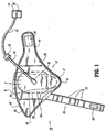
FIG. 1 is a plan view of one particular embodiment of a compression apparatus and showing an inflatable bladder and a foot in phantom, in accordance with the principles of the present disclosure; -
FIG. 1A is a partial cross-sectional view of the compression apparatus shown inFIG. 1 ; -
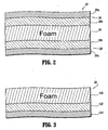
FIG. 2 is a cutaway cross section view of a strap of the compression apparatus shown inFIG. 1 ; -
FIG. 3 is a cutaway cross section view of an alternate example of the strap of the compression apparatus shown inFIG. 1 , wherein the compression apparatus having such a strap is not covered by the claims; -
FIG. 4 is a plan view of an alternate embodiment of the compression apparatus shown inFIG. 1 , illustrating an inflatable bladder in phantom; -
FIG. 5 is a plan view of another alternate embodiment of the compression apparatus shown inFIG. 1 , illustrating an inflatable bladder in phantom; -
FIG. 6 is a plan view of another alternate embodiment of the compression apparatus shown inFIG. 1 , illustrating an inflatable bladder in phantom; and -
FIG. 7 is a plan view of another alternate embodiment of the compression apparatus shown inFIG. 1 , illustrating an inflatable bladder in phantom. - The exemplary embodiments of the compression apparatus including the foot sleeve and methods of operation disclosed are discussed in terms of vascular therapy including a compression apparatus for application to a foot or other limb of a body and more particularly in terms of a compression apparatus configured to artificially stimulate the blood vessels of the limb including the foot, heel and toes of a patient. It is contemplated that the compression apparatus may be employed for preventing and overcoming the risks associated with patient immobility. It is further contemplated that the compression apparatus alleviates the conditions arising from patient immobility to prevent for example, DVT, and peripheral edema. It is contemplated that the compression apparatus according to the present disclosure may be employed with various types of venous compression systems, including, but not limited to rapid inflation, slow compression, non-sequential and sequential compression apparatus. It is envisioned that the present disclosure, however, finds application with a wide variety of immobile conditions of persons and patients alike, such as, for example, those undergoing surgery, anesthesia, extended periods of bed rest, obesity, advanced age, malignancy, and prior thromboembolism.
- In the discussion that follows, the term "subject" refers to a patient undergoing vascular therapy using the compression apparatus. The following discussion includes a description of the compression apparatus, followed by a description of an exemplary method of operating the compression apparatus in accordance with the principals of the present disclosure. Reference will now be made in detail to the exemplary embodiments and disclosure, which are illustrated with the accompanying figures.
- Turning now to the figures, wherein like components are designated by like reference numerals throughout the several views. Referring initially to
FIGS. 1 ,1A and2 , there is illustrated acompression apparatus 10, constructed in accordance with the principals of the present disclosure (see, for example, the compression sleeve described inU.S. Patent Application Serial No. 10/784,607, filed on February 23, 2004 Compression apparatus 10 includes an expandable body, such as, for example, afoot sleeve 12 configured for disposal about a foot F of a subject (not shown).Foot sleeve 12 may be disposed with the right or left foot of the subject.Foot sleeve 12 fluidly communicates with a pressurizedfluid source 14 viatubing 16 and a valve connector 18 (see, for example, the valve connector described inU.S. Patent Application Serial No. 10/784,639, filed on February 23, 2004 Compression apparatus 10 employs acontroller 20 to regulate fluid pressure for vascular therapy. See, for example, the controller described inU.S. Patent Application Serial No. 10/784,323, filed on February 23, 2004 fluid source 14 may include a pump and may be stationary or portable. It is contemplated that pressurizedfluid source 14 may include the necessary electronics and computer software to carry out vascular therapy, in accordance with the principles of the present disclosure. -
Foot sleeve 12 is configured to apply vascular therapy to the entire area of the bottom of foot F, beyond a heel H and a ball B to a substantial portion of toes T. It is contemplated thatfoot sleeve 12 or portions thereof may be disposable. It is envisioned thatfoot sleeve 12 may include flexible sections, such as, elastic or spandex materials to facilitate mobility of a limb during use. The components ofstrap 22 may be fabricated from materials suitable for compression vascular therapy such as, for example, films and fabrics, such as PVC (polyvinyl chloride) and PE (polyethylene). -
Strap 22 is configured for disposal about foot F adjacent to the ankle.Strap 22 is integrally connected to footsleeve 12 and fixedly mounted between afoot contact layer 26 and anouter layer 28 offoot sleeve 12, as will be discussed. By way of non-limiting example,foot contact layer 26 may be formed from the same contiguous material asfoot contact layer 32 offoot sleeve 12.Strap 22 has segmentedportions 24 that are configured to contour about heel H of foot F. It is contemplated thatsegmented portions 24 may be variously configured and dimensioned, such as, rounded or alternatively,strap 22 may have a uniform outer surface, such as, smooth. -
Strap 22 has a first layer, such as, for example,foot contact layer 26 that is configured to engage to an outer surface of foot F adjacent the ankle.Foot contact layer 26 includes asoft polyester material 26a that is soft for engaging the skin of the subject. This softskin contact layer 26 advantageously provides comfort to the subject, prevents contamination and mitigates skin breakdown.Foot contact layer 26 may also include a PVC portion 26b disposed adjacentsoft polyester material 26a. - A second layer, such as, for example,
outer layer 28 cooperates withfoot contact layer 26 such that athird layer 30 is disposed therebetween.Third layer 30 includes a foam material to provide a cushioning effect to the subject. It is contemplated thatlayer 30 may include alternative materials that provide a cushioned configuration.Outer layer 28 includes aloop type material 28a disposed therewith, for engagement with a corresponding hook element offoot sleeve 12, and a PVC portion 28b disposedadjacent loop material 28a.Outer layer 28 advantageously prevents contamination ofthird cushion layer 30 from the environment, such as, for example, air, moisture and dirt. -
Foot contact layer 26 andouter layer 28 are configured to form a physical barrier tothird cushion layer 30. This configuration advantageously provides comfort to the subject, as well as compliance, and prevents contamination ofthird cushioning layer 30. In an alternate example not covered by the claims, as shown inFIG. 3 ,strap 22 includes a laminate structure having acushion layer 130 and aPVC portion 132 disposed adjacent thereto. Anouter layer 134 is disposedadjacent PVC portion 132.Layer 134 may include a soft polyester material for engaging the outer surface of foot F, or alternatively, may include a loop material to prevent contamination ofcushion layer 130 from the environment. -
Foot contact layer 26 andouter layer 28 are overlaid to formstrap 22.Foot contact layer 26 andouter layer 28 are fixedly joined at seams adjacent corresponding perimeters thereof, to support the components ofstrap 22. The components ofstrap 22 may be bonded via welding, e.g., RF welding, adhesive, industrial strength double sided tape and the like. It is envisioned that only a portion of thefoot contact layer 26 andouter layer 28 are joined. It is further envisioned thatstrap 22 includes a plurality of seams, disposed variously thereabout, that joinfoot contact layer 26 andouter layer 28. - In an alternative embodiment and with reference to
FIG. 1A , an exaggerated partial cross-sectional view of astrap member 22 and its union to footsleeve 12 is shown. Thestrap member 22 is disposed between thefoot contact layer 32 andouter layer 42 offoot sleeve 12 such that the union ofstrap 22 andfoot sleeve 12 is generally uniform. Such uniformity provides additional comfort to the user of thefoot sleeve 12. More particularly,foot contact layer 26 andouter layer 28 ofstrap 22 are joined to interior portions offoot contact layer 32 andouter layer 42 offoot sleeve 12. Alternatively, it is also contemplated thatcushioning layer 30 may or may not be disposed betweenfoot contact layer 32 andouter layer 42 offoot sleeve 12. -
Strap 22 has a longitudinally projecting configuration extending fromfoot sleeve 12 and is configured for disposal about portions of foot F adjacent the ankle.Strap 22 forms part of a hook and loop type connector. A hook element 33 is mounted to strap 22 atfoot contact layer 26. Asstrap 22 is wrapped about the portions of foot F adjacent the ankle, hook element 33 engages the loop material ofouter layer 42 offoot sleeve 12 to facilitate mounting offoot sleeve 12 with foot F. Alternative to hook and loop type elements, clips, adhesive and pins may be employed. -
Foot sleeve 12 includes afoot contact layer 32 configured to engage foot F for applying pressure thereto.Foot contact layer 32 hassections 35 and is flexible for conforming to the shape of foot F. It is envisioned thatfoot contact layer 32 may be fabricated from a polyester fabric. It is contemplated thatfoot contact layer 32 may be configured for wicking fluids such as, moisture and perspiration from an outer surface of foot F.Foot contact layer 32 may be treated chemically to enhance such wicking effect. - An
inflatable bladder 34 offoot sleeve 12 includes anupper bladder layer 36 and alower bladder layer 38 that are overlaid to forminflatable bladder 34.Upper bladder layer 36 engagesfoot contact layer 32 to facilitate application of pressure for vascular therapy to foot F.Upper bladder layer 36 andlower bladder layer 38 are fixedly joined via welding at seams along their perimeters to defineinflatable bladder 34. It is contemplated thatinflatable bladder 34 may include a plurality of seams, disposed variously thereabout, that joinupper bladder layer 36 andlower bladder layer 38. It is further contemplated that the seams may be formed by adhesive, heat sealed and the like. -
Upper bladder layer 36 andlower bladder layer 38 may be fabricated from a laminated material, for example, a PVC material. It is contemplated that each bladder layer may have a thickness of approximately 6 - 15 mils. It is further contemplated that the PVC material may be laminated to a non-woven or woven material and is RF heat sealable.Upper bladder layer 36 andlower bladder layer 38 may be fabricated from two different thicknesses to provide directional inflation. It is envisioned that the overall dimensions and materials described throughout this disclosure are not limiting and that other dimensions and materials may be used. It is further envisioned thatinflatable bladder 34 may define one or a plurality of expandable chambers. -
Inflatable bladder 34 extends along foot F to apply vascular therapy to the entire area of the bottom of foot F, beyond heel H and ball B to a substantial portion of toes T. It is contemplated thatinflatable bladder 34 may have various geometric configurations, such as, circular, elliptical and rectangular.Inflatable bladder 34 includes aninlet port 40 that connects totubing 16 to facilitate fluid communication with pressurizedfluid source 14. - An
outer layer 42 offoot sleeve 12 is disposed adjacent to lowerbladder layer 38.Outer layer 42 may be fabricated from a laminated material including fabric and a loop material, for example, a loop/non-woven laminate.Outer layer 42 provides an attachment surface for hook elements. -
Outer layer 42 may include die cut holes to provide for a fluid inlet to pass through, such asinlet port 40. It is envisioned thatouter layer 42 and other portions offoot sleeve 12 may include vent openings disposed variously thereabout to provide cooling to the subject and increase mobility during use. -
Foot contact layer 32 andouter layer 42 are overlaid to formfoot sleeve 12.Foot contact layer 32 andouter layer 42 are fixedly joined at seams adjacent corresponding perimeters thereof, to support the components offoot sleeve 12. The components offoot sleeve 12 may be bonded via welding, e.g., RF welding, adhesive, industrial strength double sided tape and the like. It is envisioned that only a portion of the perimeters offoot contact layer 32 andouter layer 42 are joined. It is envisioned thatfoot sleeve 12 includes a plurality of seams, disposed variously thereabout, that joinfoot contact layer 32 andouter layer 42. - The components of
foot sleeve 12 may be fabricated from materials suitable for compression vascular therapy such as, for example, films and fabrics, such as PVC (polyvinyl chloride) and PE (polyethylene), depending on the particular vascular therapy application and/or preference. Semi-flexible and flexible fabrics, such as urethanes and silicones may also be used. Moreover,foot sleeve 12 may be fabricated from synthetic, natural, and non-woven materials of varying degrees of softness and pliability. One skilled in the art, however, will realize that other materials and fabrication methods suitable for assembly and manufacture, in accordance with the present disclosure, also would be appropriate. -
Foot sleeve 12 is configured to supportinflatable bladder 34.Foot sleeve 12 extends laterally and is configured for disposal about foot F and mounting thereto.Foot sleeve 12 is disposed with foot F such that the top portion of toes T are visible for observation and inspection. Ametatarsal flap 44 offoot sleeve 12 wraps about the side portions of foot F and transverses the instep of foot F during vascular therapy.Metatarsal flap 44 forms part of a hook and loop type connector. Ahook element 46 is mounted to footsleeve 12 atfoot contact layer 32. Asmetatarsal flap 44 is wrapped about foot F,hook element 46 engages the loop material ofouter layer 42 to facilitate mounting offoot sleeve 12 with foot F. In turn, this causesinflatable bladder 34 to be disposed about foot F for vascular therapy. This configuration offoot sleeve 12 advantageously engages foot F to augment circulation of vessels of the limb. It is contemplated thatfoot sleeve 12 may have various geometric configurations, such as, circular, elliptical, and rectangular. Alternative to hook and loop type elements, clips, adhesive, and pins may be employed. -
Compression apparatus 10, similar to that described above, is assembled and packaged for use. In operation,foot sleeve 12 ofcompression apparatus 10 is disposed about foot F and in fluid communication with pressurizedfluid source 14, as discussed.Controller 20 regulates vascular therapy ofcompression apparatus 10 to a subject.Foot sleeve 12 applies compression to foot F to provide vascular therapy to the subject and augment venous return. It is envisioned thatcompression apparatus 10 may include inflatable sleeves for disposal about various portions of a subject's limb, such as for example, thigh, calf, ankle and that a second limb may be treated in alternate compression cycles with other sleeve(s). - For example, during a selected compression cycle for
controller 20,inflatable bladder 34 is slowly inflated for 5 seconds with air to a pressure, such as 130 mm Hg. This configuration provides vascular therapy to foot F and augments venous return. At the end of the inflation and hold,foot sleeve 12 is vented andinflatable bladder 34 is deflated. Other compression cycles and pressures are also contemplated. - In an alternate embodiment,
compression apparatus 10 performs venous refill time measurement. Venous refill time (VRT) measurement is an air plethysmographic technique that determines when the veins of a limb have completely refilled with blood following a compression cycle. See, for example, the venous refill time measurement described inU.S. Patent No. 6,231,532 to Watson et al. . The VRT minimizes the amount of time that the blood remains stagnant inside the veins. The VRT is substituted for the default rest time between compression cycles. It is contemplated that the VRT technique and algorithm can be used for both leg sleeve and foot sleeve compression. - The VRT measurement uses an air plethysmographic technique where a low pressure is applied to
inflatable bladder 34. As the veins fill with blood, the pressure ininflatable bladder 34 increases until a plateau is reached. The time that it takes for the pressure to plateau is the VRT. If two sleeves are connected tocontroller 20, then the VRT is determined separately for each limb being compressed and the greater of the two measurements is used as the new vent time of the compression cycle. The VRT measurement for each sleeve is made as each particular sleeve reaches set pressure independently. However, the vent time is not updated until VRT measurements have been calculated for both sleeves. - For example,
compression apparatus 10 may employ the VRT measurement after the system initiates vascular therapy. Subsequently, after 30 minutes have elapsed, a VRT measurement will be taken on the next full inflation cycle. Afterfoot sleeve 12 inflates,inflatable bladder 34 is vented down to zero. - It is contemplated that a selected bladder pressure is monitored and the vent to the bladder is closed when the pressure falls to 5-7 mm Hg. If the pressure in the bladder is 5-7 mm Hg on a current cycle then a VRT measurement is taken. If the pressure in the bladder does not vent down to 5-7 mm Hg then the vent time will remain at its current value and another measurement will be made in 30 minutes.
- The VRT measurement algorithm determines when the pressure in
inflatable bladder 34 plateaus after compression. The VRT measurement algorithm initiates with a time counter started from the end of the inflation cycle, which occurs afterinflatable bladder 34 reaches 5-7 mm Hg (enough pressure to cause the bladder to remain in contact with the surface of the foot) and the venting is stopped. The VRT measurement initiates with the time counter started from the end of the inflation cycle. - The pressure in
inflatable bladder 34 is then monitored with a 10-second, moving sample window. The window moves in 1-second intervals. When the difference between the first and last values in the window is less than approximately 0.05 - 0.5 mm Hg, the curve has reached its plateau. The VRT measurement is considered done, and the time interval is determined. The end of the window is considered to be the point at which the venous system in the foot has refilled. - The VRT measurement is considered erroneous if at any time during the measurement, the pressure in
inflatable bladder 34 is below 2 mmHg, the calculation is discarded, and the old value of VRT is used. This may occur if there is a leak in the system. It is contemplated that if the pressure is greater than 20 mmHg at any time during the VRT measurement, the old value of the VRT is used. - Referring to
FIG. 4 , an alternate embodiment ofcompression apparatus 10 is shown.Compression apparatus 10 includes afoot sleeve 212, similar tofoot sleeve 12 described above with regard toFIGS. 1 ,1A and2 , configured for disposal about foot F. A pair ofstraps 222, similar tostrap 22 described above with regard toFIGS. 1 ,1A and2 , extend fromfoot sleeve 212.Straps 222 are configured for disposal about foot F adjacent to the ankle. One or a plurality ofstraps 222 may be employed. -
Straps 222 have a longitudinally projecting configuration extending fromfoot sleeve 212 and are configured for disposal about portions of foot F adjacent the ankle. As discussed herein, it is contemplated thatstraps 222 may be separately or monolithically formed withfoot sleeve 212.Straps 222 form part of hook and loop type connectors.Hook element 232 andloop element 232a are mounted to straps 222. As each ofstraps 222 are wrapped about the portions of foot F adjacent the ankle,hook element 232 engagesloop material 232a to facilitate mounting offoot sleeve 212 with foot F. It is contemplated thathook elements foot sleeve 212 to facilitate mounting offoot sleeve 212 with foot F. - An
inflatable bladder 234, similar tobladder 34 described above with regard toFIGS. 1 and2 , extends longitudinally along foot F to apply vascular therapy to the entire area of the bottom of foot F, beyond heel H and ball B to a substantial portion of toesT. Inflatable bladder 234 includes aninlet port 240 that connects totubing 16 to facilitate fluid communication with pressurizedfluid source 14. -
Foot sleeve 212 is configured to supportinflatable bladder 234.Foot sleeve 212 extends laterally and is configured for disposal about foot F and mounting thereto.Foot sleeve 212 is disposed with foot F such that the top portion of toes T are visible for observation and inspection. A pair of metatarsal flaps 244 extend laterally fromfoot sleeve 212 for wrapping about the side portions of foot F and transversing the instep of foot F during vascular therapy. Metatarsal flaps 244 form the hook and loop type connectors.Hook element 246 andloop element 246a are mounted tofoot sleeve 212. As metatarsal flaps 244 are wrapped about foot F,hook element 246 engages toloop element 246a to engage thefoot sleeve 212 to facilitate mounting offoot sleeve 212 with foot F. In turn, this causesinflatable bladder 234 to be disposed about foot F for vascular therapy. This configuration offoot sleeve 212 advantageously engages foot F to augment circulation of vessels of the limb.Foot sleeve 212 includesvent openings 250 disposed to provide cooling to the subject and increase mobility during use. - Referring to
FIG. 5 , another alternate embodiment ofcompression apparatus 10 is shown.Compression apparatus 10 includes afoot sleeve 312, similar to those described above, configured for disposal about foot F. Astrap 322, similar to those described above, extends fromfoot sleeve 312. Aninflatable bladder 334, similar to those described above, extends longitudinally along foot F to apply vascular therapy to the entire area of the bottom of foot F, beyond heel H and ball B to a substantial portion of toesT. Inflatable bladder 334 includesside portions 336 that extend laterally therefrom to engage side portions of foot F during application offoot sleeve 312 with foot F. -
Foot sleeve 312 is configured to supportinflatable bladder 334.Foot sleeve 312 extends laterally and is configured for disposal about foot F and mounting thereto.Foot sleeve 312 is disposed with foot F such that the top portion of toes T are visible for observation and inspection. A pair of metatarsal flaps 344 extend laterally from one side offoot sleeve 312 for wrapping about the side portions of foot F and transversing the instep of foot F during vascular therapy. Metatarsal flaps 344 form part of hook and loop type connectors.Hook elements foot sleeve 312. As metatarsal flaps 344 are wrapped about foot F, hookelements foot sleeve 312 to facilitate mounting offoot sleeve 312 with foot F. In turn, this causesinflatable bladder 334 to be disposed about foot F, includingside portions 336 engaging the side portions of foot F, for vascular therapy. This configuration offoot sleeve 312 advantageously engages foot F to augment circulation of vessels of the limb. - Referring to
FIG. 6 , another alternate embodiment ofcompression apparatus 10 is shown.Compression apparatus 10 includes afoot sleeve 412, similar to those described above, configured for disposal about foot F. Astrap 422, similar to those described above, extends fromfoot sleeve 412. Aninflatable bladder 434, similar to those described above, extends longitudinally along foot F to apply vascular therapy to the bottom of foot F, beyond heel H and ball B to a substantial portion of toes T. -
Foot sleeve 412 has wings 444 (similar to metatarsal flaps described above) and is configured to supportinflatable bladder 434.Foot sleeve 412 extends laterally, viawings 444, and is configured for disposal about foot F and mounting thereto.Foot sleeve 412 is disposed with foot F such that the top portion of toes T are visible for observation and inspection.Wings 444 wrap about the side portions of foot F and transverse the instep of foot F during vascular therapy.Wings 444 form part of hook and loop type connectors.Hook element 446 andloop element 446a are mounted towings 444. Aswings 444 are wrapped about foot F,hook element 446 engages withloop element 446a to facilitate mounting offoot sleeve 412 with foot F. In turn, this causesinflatable bladder 434 to be disposed about foot F for vascular therapy. This configuration offoot sleeve 412 advantageously engages foot F to augment circulation of vessels of the limb. - Referring to
FIG. 7 , another alternate embodiment ofcompression apparatus 10 is shown.Compression apparatus 10 includes afoot sleeve 512, similar to those described above, configured for disposal about foot F. Astrap 522, similar to those described above, extends fromfoot sleeve 512. Aninflatable bladder 534, similar to those described above, extends longitudinally along foot F to apply vascular therapy to the bottom of foot F, beyond heel H and ball B to a substantial portion of toesT. Inflatable bladder 534 includeslongitudinal portions 536 that extend longitudinally therefrom to engage desired portions of the bottom of foot F during application offoot sleeve 512 with footF. Foot sleeve 512 is configured to supportinflatable bladder 534. This configuration offoot sleeve 512 advantageously engages foot F to augment circulation of vessels of the limb. - It will be understood that various modifications may be made to the embodiments disclosed herein. Therefore, the above description should not be construed as limiting, but merely as exemplification of the various embodiments. Those skilled in the art will envision other modifications within the scope of the claims appended hereto.
Claims (6)
- A compression apparatus (10) comprising:a foot sleeve (12) including an inflatable body (34) configured for disposal about a foot and having a foot contact layer (32) and an outer layer (42), the foot contact layer and the outer layer being overlaid to form the foot sleeve and fixedly joined at seams adjacent corresponding perimeters thereof, the foot sleeve including a metatarsal portion (44);a strap (22) fixedly connected to the foot sleeve and extending therefrom, the strap being configured for disposal about the foot adjacent an ankle,wherein the strap has a first layer (26) configured to engage an outer surface of the foot adjacent the ankle and a second outer layer (28) characterized in that the strap further comprises a third cushion layer (30) disposed between the first and second layers of the strap such that the first layer and the second layer are configured to provide a barrier to the third cushion layer, and in that a portion of the strap is sandwiched between the foot contact layer and the outer layer of the foot sleeve at said perimeters and permanently secured thereto.
- A compression apparatus as recited in claim 1, wherein the first layer (26) is configured to prevent engagement of the third cushion layer (30) with the outer surface of the foot.
- A compression apparatus as recited in claim 1, wherein the third cushion layer (30) includes a foam material.
- A compression apparatus as recited in claim 1, wherein the strap (22) has a segmented configuration for contour with the foot.
- A compression apparatus as recited in claim 1, wherein the first layer (26) of the strap (22) includes a soft material that is configured to engage the outer surface of the foot adjacent the ankle, wherein the second layer of the strap has an outer surface including a loop material (28a) such that the metatarsal portion (44) includes hook elements (46) that are engageable with the loop material to mount the foot sleeve (12) with the foot, and wherein the third cushion layer (30) includes foam material.
- A compression apparatus as recited in claim 1, wherein the compression apparatus includes a plurality of straps extending from the foot sleeve.
Priority Applications (1)
| Application Number | Priority Date | Filing Date | Title |
|---|---|---|---|
| PL05723526T PL1720505T3 (en) | 2004-02-23 | 2005-02-23 | Compression apparatus |
Applications Claiming Priority (5)
| Application Number | Priority Date | Filing Date | Title |
|---|---|---|---|
| US10/784,639 US7490620B2 (en) | 2004-02-23 | 2004-02-23 | Fluid conduit connector apparatus |
| US10/784,607 US7871387B2 (en) | 2004-02-23 | 2004-02-23 | Compression sleeve convertible in length |
| US10/784,604 US7282038B2 (en) | 2004-02-23 | 2004-02-23 | Compression apparatus |
| US10/784,323 US7354410B2 (en) | 2004-02-23 | 2004-02-23 | Compression treatment system |
| PCT/US2005/005679 WO2005082316A2 (en) | 2004-02-23 | 2005-02-23 | Compression apparatus |
Publications (2)
| Publication Number | Publication Date |
|---|---|
| EP1720505A2 EP1720505A2 (en) | 2006-11-15 |
| EP1720505B1 true EP1720505B1 (en) | 2011-12-14 |
Family
ID=34916527
Family Applications (6)
| Application Number | Title | Priority Date | Filing Date |
|---|---|---|---|
| EP05723526A Not-in-force EP1720505B1 (en) | 2004-02-23 | 2005-02-23 | Compression apparatus |
| EP10185262.2A Withdrawn EP2319476A3 (en) | 2004-02-23 | 2005-02-23 | Compression treatment system |
| EP10185260.6A Active EP2314268B1 (en) | 2004-02-23 | 2005-02-23 | Compression treatment system |
| EP05713934A Not-in-force EP1718894B1 (en) | 2004-02-23 | 2005-02-23 | Fluid conduit connector apparatus |
| EP05713935A Active EP1720504B1 (en) | 2004-02-23 | 2005-02-23 | Compression apparatus |
| EP05713933.9A Active EP1722738B1 (en) | 2004-02-23 | 2005-02-23 | Compression treatment system |
Family Applications After (5)
| Application Number | Title | Priority Date | Filing Date |
|---|---|---|---|
| EP10185262.2A Withdrawn EP2319476A3 (en) | 2004-02-23 | 2005-02-23 | Compression treatment system |
| EP10185260.6A Active EP2314268B1 (en) | 2004-02-23 | 2005-02-23 | Compression treatment system |
| EP05713934A Not-in-force EP1718894B1 (en) | 2004-02-23 | 2005-02-23 | Fluid conduit connector apparatus |
| EP05713935A Active EP1720504B1 (en) | 2004-02-23 | 2005-02-23 | Compression apparatus |
| EP05713933.9A Active EP1722738B1 (en) | 2004-02-23 | 2005-02-23 | Compression treatment system |
Country Status (15)
| Country | Link |
|---|---|
| EP (6) | EP1720505B1 (en) |
| JP (4) | JP4602996B2 (en) |
| KR (5) | KR100873540B1 (en) |
| CN (1) | CN102614074B (en) |
| AT (3) | ATE536851T1 (en) |
| AU (4) | AU2005216934B2 (en) |
| CA (4) | CA2552355C (en) |
| DE (2) | DE602005021460D1 (en) |
| DK (1) | DK1720504T3 (en) |
| ES (4) | ES2806930T3 (en) |
| HK (1) | HK1091390A1 (en) |
| IL (4) | IL176409A (en) |
| NO (4) | NO20064255L (en) |
| PL (2) | PL1720505T3 (en) |
| WO (4) | WO2005083313A1 (en) |
Families Citing this family (62)
| Publication number | Priority date | Publication date | Assignee | Title |
|---|---|---|---|---|
| GB0515294D0 (en) | 2005-07-26 | 2005-08-31 | Novamedix Distrib Ltd | Limited durability closure means for an inflatable medical garment |
| GB0523249D0 (en) * | 2005-11-15 | 2005-12-21 | Huntleigh Technology Plc | Identification means |
| US8029451B2 (en) | 2005-12-12 | 2011-10-04 | Tyco Healthcare Group Lp | Compression sleeve having air conduits |
| GB0601453D0 (en) * | 2006-01-24 | 2006-03-08 | Bristol Myers Squibb Co | Pressurised medical device |
| JP4710758B2 (en) * | 2006-08-28 | 2011-06-29 | パナソニック電工株式会社 | Massage machine |
| GB0622415D0 (en) | 2006-11-10 | 2006-12-20 | Huntleigh Technology Plc | Compression system |
| US8109892B2 (en) | 2007-04-09 | 2012-02-07 | Tyco Healthcare Group Lp | Methods of making compression device with improved evaporation |
| US8506508B2 (en) | 2007-04-09 | 2013-08-13 | Covidien Lp | Compression device having weld seam moisture transfer |
| US8070699B2 (en) | 2007-04-09 | 2011-12-06 | Tyco Healthcare Group Lp | Method of making compression sleeve with structural support features |
| US8016779B2 (en) * | 2007-04-09 | 2011-09-13 | Tyco Healthcare Group Lp | Compression device having cooling capability |
| US8034007B2 (en) | 2007-04-09 | 2011-10-11 | Tyco Healthcare Group Lp | Compression device with structural support features |
| US8016778B2 (en) | 2007-04-09 | 2011-09-13 | Tyco Healthcare Group Lp | Compression device with improved moisture evaporation |
| US8128584B2 (en) * | 2007-04-09 | 2012-03-06 | Tyco Healthcare Group Lp | Compression device with S-shaped bladder |
| US8021388B2 (en) | 2007-04-09 | 2011-09-20 | Tyco Healthcare Group Lp | Compression device with improved moisture evaporation |
| US8162861B2 (en) | 2007-04-09 | 2012-04-24 | Tyco Healthcare Group Lp | Compression device with strategic weld construction |
| US8029450B2 (en) | 2007-04-09 | 2011-10-04 | Tyco Healthcare Group Lp | Breathable compression device |
| US8182437B2 (en) | 2007-05-08 | 2012-05-22 | Wright Therapy Products, Inc. | Pneumatic compression therapy system and methods of using same |
| EP2162109A4 (en) | 2007-06-20 | 2012-10-03 | Remo Moomiaie-Qajar | Portable compression device |
| GB0712764D0 (en) | 2007-07-02 | 2007-08-08 | Smith & Nephew | Carrying Bag |
| US8246028B2 (en) | 2007-11-08 | 2012-08-21 | Tyco Healthcare Group Lp | Telescopingly adjustable clamp |
| US8114117B2 (en) | 2008-09-30 | 2012-02-14 | Tyco Healthcare Group Lp | Compression device with wear area |
| US8235923B2 (en) | 2008-09-30 | 2012-08-07 | Tyco Healthcare Group Lp | Compression device with removable portion |
| US8133039B2 (en) | 2009-01-26 | 2012-03-13 | Tyco Healthcare Group Lp | Mount for a compression control unit |
| US8419666B2 (en) * | 2009-09-23 | 2013-04-16 | Caremed Supply, Inc. | Compression sleeve |
| US8506507B2 (en) * | 2010-03-09 | 2013-08-13 | Covidien Lp | Venous augmentation system |
| US8652079B2 (en) | 2010-04-02 | 2014-02-18 | Covidien Lp | Compression garment having an extension |
| USD675741S1 (en) | 2010-08-16 | 2013-02-05 | Covidien Lp | Pneumatic compression controller |
| USD659839S1 (en) | 2010-08-16 | 2012-05-15 | Tyco Healthcare Group Lp | Support for a pneumatic compression controller |
| US10751221B2 (en) | 2010-09-14 | 2020-08-25 | Kpr U.S., Llc | Compression sleeve with improved position retention |
| US8398572B2 (en) * | 2010-09-21 | 2013-03-19 | Covidien Lp | Bladder tube connection |
| US8758282B2 (en) | 2010-09-29 | 2014-06-24 | Covidien Lp | Compression garment apparatus having support bladder |
| US8753300B2 (en) * | 2010-09-29 | 2014-06-17 | Covidien Lp | Compression garment apparatus having baseline pressure |
| CA2778395A1 (en) * | 2011-06-10 | 2012-12-10 | Tyco Healthcare Group Lp | Compression device having a pause feature |
| US10828402B2 (en) * | 2011-10-14 | 2020-11-10 | Alcon Inc. | Collar connector |
| AU2013232352B2 (en) | 2012-03-12 | 2017-10-12 | Tactile Systems Technology, Inc. | Compression therapy device with multiple simultaneously active chambers |
| US9889063B2 (en) * | 2012-06-11 | 2018-02-13 | Wright Therapy Products, Inc. | Methods and systems for determining use compliance of a compression therapy device |
| US9205021B2 (en) | 2012-06-18 | 2015-12-08 | Covidien Lp | Compression system with vent cooling feature |
| SG11201500759PA (en) * | 2012-07-30 | 2015-03-30 | Univ Kochi Nat Univ Corp | In vivo acetylcholine production-promoting device |
| US9737238B2 (en) | 2012-08-18 | 2017-08-22 | Wright Therapy Products, Inc. | Methods for determining the size of body parts as part of compression therapy procedures |
| US9872812B2 (en) | 2012-09-28 | 2018-01-23 | Kpr U.S., Llc | Residual pressure control in a compression device |
| USD764654S1 (en) | 2014-03-13 | 2016-08-23 | Smith & Nephew, Inc. | Canister for collecting wound exudate |
| US9295605B2 (en) | 2013-12-02 | 2016-03-29 | Wright Therapy Products, Inc. | Methods and systems for auto-calibration of a pneumatic compression device |
| US10470967B2 (en) | 2014-01-20 | 2019-11-12 | Tactile Systems Technology, Inc. | Bespoke compression therapy device |
| US10292894B2 (en) | 2014-02-11 | 2019-05-21 | Tactile Systems Technology, Inc. | Compression therapy device and compression therapy protocols |
| USD764653S1 (en) | 2014-05-28 | 2016-08-23 | Smith & Nephew, Inc. | Canister for collecting wound exudate |
| USD764047S1 (en) | 2014-05-28 | 2016-08-16 | Smith & Nephew, Inc. | Therapy unit assembly |
| USD764048S1 (en) | 2014-05-28 | 2016-08-16 | Smith & Nephew, Inc. | Device for applying negative pressure to a wound |
| USD765830S1 (en) | 2014-06-02 | 2016-09-06 | Smith & Nephew, Inc. | Therapy unit assembly |
| USD770173S1 (en) | 2014-06-02 | 2016-11-01 | Smith & Nephew, Inc. | Bag |
| US10071011B2 (en) * | 2014-06-30 | 2018-09-11 | Kpr U.S., Llc | Compression garment inflation |
| CA2959031A1 (en) * | 2014-08-27 | 2016-03-03 | Covidien Lp | Compression garment inflation |
| US10441458B2 (en) | 2015-01-27 | 2019-10-15 | Medicance Incorporated | Medical pad and system for thermotherapy |
| DE102015105371A1 (en) * | 2015-04-09 | 2016-10-13 | Kongsberg Automotive Ab | Massage device for a vehicle seat |
| US10166164B2 (en) | 2016-04-27 | 2019-01-01 | Radial Medical, Inc. | Adaptive compression therapy systems and methods |
| JP2019519284A (en) * | 2016-05-26 | 2019-07-11 | ハントレイ テクノロジー リミテッドHuntleigh Technology Limited | Compression therapy system and method |
| WO2018230930A1 (en) * | 2017-06-16 | 2018-12-20 | 주식회사 뷰엘리스 | Leg cuff for pneumatic massage |
| WO2019183617A1 (en) | 2018-03-23 | 2019-09-26 | TurnCare, Inc. | Inflatable perfusion enhancement apparatuses and associated devices, systems and methods |
| US11504927B2 (en) | 2018-03-23 | 2022-11-22 | TurnCare, Inc. | Systems and methods for controlling and monitoring inflatable perfusion enhancement apparatus for mitigating contact pressure |
| US10893998B2 (en) | 2018-10-10 | 2021-01-19 | Inova Labs Inc. | Compression apparatus and systems for circulatory disorders |
| KR20220019182A (en) | 2020-08-07 | 2022-02-16 | 유인종 | An air pressure control apparatus for treatment apparatus of varicose vein and the treatment apparatus comprising the same |
| KR20220019180A (en) | 2020-08-07 | 2022-02-16 | 유인종 | A compression stocking for treatment apparatus of varicose vein and the fabrication method thereof, and the treatment apparatus comprising the same |
| JP7283816B1 (en) * | 2022-02-17 | 2023-05-30 | 株式会社テクノ高槻 | Air supply and exhaust system |
Family Cites Families (47)
| Publication number | Priority date | Publication date | Assignee | Title |
|---|---|---|---|---|
| US1883240A (en) * | 1925-11-27 | 1932-10-18 | Honeywell Regulator Co | Magnetically operated valve |
| US1608239A (en) * | 1925-12-09 | 1926-11-23 | Rosett Joshua | Therapeutic device |
| US2628850A (en) * | 1949-03-19 | 1953-02-17 | Donald V Summerville | Releasable conduit connection with automatic valving |
| US4013069A (en) * | 1975-10-28 | 1977-03-22 | The Kendall Company | Sequential intermittent compression device |
| US4091804A (en) * | 1976-12-10 | 1978-05-30 | The Kendall Company | Compression sleeve |
| US4355632A (en) * | 1980-08-06 | 1982-10-26 | Jobst Institute, Inc. | Anti-shock pressure garment |
| US4374518A (en) * | 1980-10-09 | 1983-02-22 | Raul Villanueva | Electronic device for pneumomassage to reduce lymphedema |
| JPS5942030Y2 (en) * | 1980-12-23 | 1984-12-06 | 株式会社日器 | Pressure bag for pneumatic pine surge device |
| IL63574A (en) | 1981-08-14 | 1985-07-31 | Mego Afek | Massaging sleeve for body limbs |
| JPS5892926U (en) * | 1981-12-17 | 1983-06-23 | 日東工器株式会社 | Compressed air supply device for pneumatic pine surger |
| US4624248A (en) * | 1983-02-07 | 1986-11-25 | David Clark Company Incorporated | Transparent pressure garment |
| US4696289C1 (en) * | 1983-06-22 | 2002-09-03 | Novamedix Distrib Ltd | Method of stimulating the venous-pump mechanism of the foot and for enhancement of arterial flow to the foot |
| US5989204A (en) * | 1991-09-27 | 1999-11-23 | Kinetic Concepts, Inc. | Foot-mounted venous compression device |
| US5186163A (en) * | 1991-11-25 | 1993-02-16 | The Kendall Company | Compression device |
| EP0861652B1 (en) * | 1991-12-17 | 2002-04-17 | Kinetic Concepts, Inc. | Pneumatic compression device and methods for use in the medical field |
| GB2295458B (en) * | 1992-09-15 | 1996-08-14 | Huntleigh Technology Plc | DVT prevention apparatus and method |
| JPH06245949A (en) * | 1993-02-22 | 1994-09-06 | Hokoku Kogyo Co Ltd | Warming/cooling massage medical treatment device |
| US5354260A (en) * | 1993-05-13 | 1994-10-11 | Novamedix, Ltd. | Slipper with an inflatable foot pump |
| US5443440A (en) * | 1993-06-11 | 1995-08-22 | Ndm Acquisition Corp. | Medical pumping apparatus |
| US5478119A (en) * | 1993-09-16 | 1995-12-26 | The Kendall Company | Polarized manifold connection device |
| US5795312A (en) * | 1993-09-27 | 1998-08-18 | The Kendall Company | Compression sleeve |
| US5575762A (en) * | 1994-04-05 | 1996-11-19 | Beiersdorf-Jobst, Inc. | Gradient sequential compression system and method for reducing the occurrence of deep vein thrombosis |
| US5591200A (en) * | 1994-06-17 | 1997-01-07 | World, Inc. | Method and apparatus for applying pressure to a body limb for treating edema |
| CA2153375C (en) * | 1994-07-26 | 2000-09-12 | Arnold Tobler | Attachment of hook and loop fastener to a compression sleeve |
| US5876359A (en) | 1994-11-14 | 1999-03-02 | Bock; Malcolm G. | Sequential compression device controller |
| GB9507328D0 (en) * | 1995-04-08 | 1995-05-31 | Novamedix Ltd | A medical device |
| JPH09313557A (en) * | 1996-05-31 | 1997-12-09 | Megoafeck Ind Measuring Instr | Pneumatic massaging device |
| IL120935A0 (en) * | 1996-06-07 | 1997-09-30 | Bibi Roni | Medical apparatus for facilitating blood circulation in the lower limbs |
| US5681339A (en) * | 1996-08-12 | 1997-10-28 | Mcewen; James A. | Apparatus and method for monitoring the patency of tubing in a pneumatic medical device |
| JP4124503B2 (en) * | 1997-06-06 | 2008-07-23 | 株式会社アドバンス | Blood circulation promotion device |
| JP4059956B2 (en) * | 1997-06-30 | 2008-03-12 | 日東工器株式会社 | Pneumatic massager |
| DE69819910T2 (en) * | 1997-08-31 | 2004-09-02 | Medical Compression Systems (D.B.N.) | DEVICE FOR COMPRESSION TREATMENT OF LIMBS |
| US6494852B1 (en) | 1998-03-11 | 2002-12-17 | Medical Compression Systems (Dbn) Ltd. | Portable ambulant pneumatic compression system |
| US6007559A (en) * | 1998-06-12 | 1999-12-28 | Aci Medical | Vascular assist methods and apparatus |
| JP2002521137A (en) * | 1998-07-30 | 2002-07-16 | メディカル ダイナミックス ユーエスエイ, エルエルシー | Medical device for applying periodic therapeutic actions to a human foot |
| US6062244A (en) * | 1998-08-13 | 2000-05-16 | Aci Medical | Fluidic connector |
| DE19846922C2 (en) * | 1998-10-12 | 2003-12-11 | Manuel Fernandez | treatment device |
| JP3909789B2 (en) * | 1998-12-28 | 2007-04-25 | 日東工器株式会社 | Air massager |
| CN1330285C (en) * | 1999-01-11 | 2007-08-08 | 家族株式会社 | Massaging machine |
| FR2789811B1 (en) | 1999-02-11 | 2001-05-18 | Radiall Sa | COAXIAL CONNECTION FOR CONNECTING TWO PRINTED CIRCUIT BOARDS |
| US6290662B1 (en) | 1999-05-28 | 2001-09-18 | John K. Morris | Portable, self-contained apparatus for deep vein thrombosis (DVT) prophylaxis |
| US6592534B1 (en) * | 1999-12-27 | 2003-07-15 | Aircast, Inc. | Inflatable medical appliance for prevention of DVT |
| JP2001286521A (en) * | 2000-04-10 | 2001-10-16 | Nippon Colin Co Ltd | Vein thrombus embolism preventing device |
| US6558338B1 (en) * | 2000-11-20 | 2003-05-06 | Mego Afek Industrial Measuring Instruments | System for and method of applying pressure to human body |
| JP3951637B2 (en) * | 2001-06-14 | 2007-08-01 | 松下電工株式会社 | Air massage machine |
| JP2003319988A (en) * | 2002-05-07 | 2003-11-11 | Marutaka Co Ltd | Air massage machine for arm |
| US20050242315A1 (en) * | 2002-07-27 | 2005-11-03 | Lund Niels K | Rapid coupling device and method for assembling a coupling socket |
-
2005
- 2005-02-23 CA CA002552355A patent/CA2552355C/en not_active Expired - Fee Related
- 2005-02-23 AU AU2005216934A patent/AU2005216934B2/en not_active Ceased
- 2005-02-23 WO PCT/US2005/005599 patent/WO2005083313A1/en active Application Filing
- 2005-02-23 PL PL05723526T patent/PL1720505T3/en unknown
- 2005-02-23 AU AU2005216924A patent/AU2005216924B2/en active Active
- 2005-02-23 JP JP2006554297A patent/JP4602996B2/en not_active Expired - Fee Related
- 2005-02-23 CA CA002552331A patent/CA2552331C/en not_active Expired - Fee Related
- 2005-02-23 JP JP2006554296A patent/JP4571156B2/en active Active
- 2005-02-23 PL PL05713935T patent/PL1720504T3/en unknown
- 2005-02-23 AU AU2005217424A patent/AU2005217424B2/en not_active Ceased
- 2005-02-23 WO PCT/US2005/005600 patent/WO2005082315A1/en active Application Filing
- 2005-02-23 KR KR1020067016795A patent/KR100873540B1/en active IP Right Grant
- 2005-02-23 ES ES10185260T patent/ES2806930T3/en active Active
- 2005-02-23 CA CA2552354A patent/CA2552354C/en not_active Expired - Fee Related
- 2005-02-23 EP EP05723526A patent/EP1720505B1/en not_active Not-in-force
- 2005-02-23 EP EP10185262.2A patent/EP2319476A3/en not_active Withdrawn
- 2005-02-23 EP EP10185260.6A patent/EP2314268B1/en active Active
- 2005-02-23 WO PCT/US2005/005598 patent/WO2005082314A1/en active Application Filing
- 2005-02-23 AT AT05723526T patent/ATE536851T1/en active
- 2005-02-23 DE DE602005021460T patent/DE602005021460D1/en active Active
- 2005-02-23 ES ES05723526T patent/ES2378886T3/en active Active
- 2005-02-23 AU AU2005216923A patent/AU2005216923B2/en active Active
- 2005-02-23 ES ES05713935T patent/ES2346546T3/en active Active
- 2005-02-23 EP EP05713934A patent/EP1718894B1/en not_active Not-in-force
- 2005-02-23 KR KR1020067016796A patent/KR100914569B1/en active IP Right Grant
- 2005-02-23 ES ES05713933T patent/ES2414880T3/en active Active
- 2005-02-23 DK DK05713935.4T patent/DK1720504T3/en active
- 2005-02-23 CA CA002552353A patent/CA2552353C/en not_active Expired - Fee Related
- 2005-02-23 EP EP05713935A patent/EP1720504B1/en active Active
- 2005-02-23 JP JP2006554298A patent/JP4686485B2/en not_active Expired - Fee Related
- 2005-02-23 CN CN201210098027.XA patent/CN102614074B/en active Active
- 2005-02-23 WO PCT/US2005/005679 patent/WO2005082316A2/en active Application Filing
- 2005-02-23 KR KR1020067016843A patent/KR20070001964A/en active Search and Examination
- 2005-02-23 AT AT05713934T patent/ATE473390T1/en active
- 2005-02-23 JP JP2006554310A patent/JP2007522892A/en active Pending
- 2005-02-23 KR KR1020067016842A patent/KR100868148B1/en active IP Right Grant
- 2005-02-23 AT AT05713935T patent/ATE468834T1/en not_active IP Right Cessation
- 2005-02-23 EP EP05713933.9A patent/EP1722738B1/en active Active
- 2005-02-23 DE DE602005022165T patent/DE602005022165D1/en active Active
- 2005-02-23 KR KR1020087023566A patent/KR100918718B1/en active IP Right Grant
-
2006
- 2006-06-19 IL IL176409A patent/IL176409A/en active IP Right Grant
- 2006-06-19 IL IL176410A patent/IL176410A/en active IP Right Grant
- 2006-06-20 IL IL176432A patent/IL176432A0/en unknown
- 2006-06-20 IL IL176433A patent/IL176433A/en active IP Right Grant
- 2006-09-20 NO NO20064255A patent/NO20064255L/en not_active Application Discontinuation
- 2006-09-20 NO NO20064256A patent/NO20064256L/en not_active Application Discontinuation
- 2006-09-21 NO NO20064281A patent/NO20064281L/en not_active Application Discontinuation
- 2006-09-22 NO NO20064310A patent/NO20064310L/en not_active Application Discontinuation
- 2006-12-04 HK HK06113291.3A patent/HK1091390A1/en not_active IP Right Cessation
Also Published As
Similar Documents
| Publication | Publication Date | Title |
|---|---|---|
| EP1720505B1 (en) | Compression apparatus | |
| US7282038B2 (en) | Compression apparatus | |
| AU2017325804B2 (en) | Therapeutic compression apparatus and methods of use | |
| EP1795168B1 (en) | Compression apparatus | |
| EP1809230B1 (en) | Compression device for the limb | |
| EP0897707B1 (en) | Compression system | |
| US20070282230A1 (en) | Systems and methods for applying reversed sequence pressure to control edema flow | |
| WO2009064822A1 (en) | Method and assembly for treating venous ulcers and wounds | |
| US20120316480A1 (en) | Therapeutic compression apparatus | |
| EP2671560A1 (en) | Compression garment including bladder having reduced inflatable volume | |
| AU2011223991B2 (en) | Compression garment having grip | |
| WO2012142155A2 (en) | Therapeutic compression apparatus | |
| WO1999037266A1 (en) | Venous boot | |
| WO2020022973A2 (en) | Wearable anti-embolism stockings |
Legal Events
| Date | Code | Title | Description |
|---|---|---|---|
| PUAI | Public reference made under article 153(3) epc to a published international application that has entered the european phase |
Free format text: ORIGINAL CODE: 0009012 |
|
| 17P | Request for examination filed |
Effective date: 20060623 |
|
| AK | Designated contracting states |
Kind code of ref document: A2 Designated state(s): AT BE BG CH CY CZ DE DK EE ES FI FR GB GR HU IE IS IT LI LT LU MC NL PL PT RO SE SI SK TR |
|
| REG | Reference to a national code |
Ref country code: HK Ref legal event code: DE Ref document number: 1091389 Country of ref document: HK |
|
| DAX | Request for extension of the european patent (deleted) | ||
| 17Q | First examination report despatched |
Effective date: 20080808 |
|
| GRAP | Despatch of communication of intention to grant a patent |
Free format text: ORIGINAL CODE: EPIDOSNIGR1 |
|
| GRAS | Grant fee paid |
Free format text: ORIGINAL CODE: EPIDOSNIGR3 |
|
| GRAA | (expected) grant |
Free format text: ORIGINAL CODE: 0009210 |
|
| AK | Designated contracting states |
Kind code of ref document: B1 Designated state(s): AT BE BG CH CY CZ DE DK EE ES FI FR GB GR HU IE IS IT LI LT LU MC NL PL PT RO SE SI SK TR |
|
| REG | Reference to a national code |
Ref country code: GB Ref legal event code: FG4D |
|
| REG | Reference to a national code |
Ref country code: CH Ref legal event code: EP |
|
| REG | Reference to a national code |
Ref country code: IE Ref legal event code: FG4D |
|
| REG | Reference to a national code |
Ref country code: DE Ref legal event code: R096 Ref document number: 602005031646 Country of ref document: DE Effective date: 20120308 |
|
| REG | Reference to a national code |
Ref country code: NL Ref legal event code: VDEP Effective date: 20111214 |
|
| REG | Reference to a national code |
Ref country code: ES Ref legal event code: FG2A Ref document number: 2378886 Country of ref document: ES Kind code of ref document: T3 Effective date: 20120418 |
|
| PG25 | Lapsed in a contracting state [announced via postgrant information from national office to epo] |
Ref country code: LT Free format text: LAPSE BECAUSE OF FAILURE TO SUBMIT A TRANSLATION OF THE DESCRIPTION OR TO PAY THE FEE WITHIN THE PRESCRIBED TIME-LIMIT Effective date: 20111214 |
|
| LTIE | Lt: invalidation of european patent or patent extension |
Effective date: 20111214 |
|
| PG25 | Lapsed in a contracting state [announced via postgrant information from national office to epo] |
Ref country code: GR Free format text: LAPSE BECAUSE OF FAILURE TO SUBMIT A TRANSLATION OF THE DESCRIPTION OR TO PAY THE FEE WITHIN THE PRESCRIBED TIME-LIMIT Effective date: 20120315 Ref country code: NL Free format text: LAPSE BECAUSE OF FAILURE TO SUBMIT A TRANSLATION OF THE DESCRIPTION OR TO PAY THE FEE WITHIN THE PRESCRIBED TIME-LIMIT Effective date: 20111214 Ref country code: SE Free format text: LAPSE BECAUSE OF FAILURE TO SUBMIT A TRANSLATION OF THE DESCRIPTION OR TO PAY THE FEE WITHIN THE PRESCRIBED TIME-LIMIT Effective date: 20111214 Ref country code: SI Free format text: LAPSE BECAUSE OF FAILURE TO SUBMIT A TRANSLATION OF THE DESCRIPTION OR TO PAY THE FEE WITHIN THE PRESCRIBED TIME-LIMIT Effective date: 20111214 |
|
| REG | Reference to a national code |
Ref country code: PL Ref legal event code: T3 |
|
| PG25 | Lapsed in a contracting state [announced via postgrant information from national office to epo] |
Ref country code: BE Free format text: LAPSE BECAUSE OF FAILURE TO SUBMIT A TRANSLATION OF THE DESCRIPTION OR TO PAY THE FEE WITHIN THE PRESCRIBED TIME-LIMIT Effective date: 20111214 Ref country code: CY Free format text: LAPSE BECAUSE OF FAILURE TO SUBMIT A TRANSLATION OF THE DESCRIPTION OR TO PAY THE FEE WITHIN THE PRESCRIBED TIME-LIMIT Effective date: 20111214 |
|
| PG25 | Lapsed in a contracting state [announced via postgrant information from national office to epo] |
Ref country code: IS Free format text: LAPSE BECAUSE OF FAILURE TO SUBMIT A TRANSLATION OF THE DESCRIPTION OR TO PAY THE FEE WITHIN THE PRESCRIBED TIME-LIMIT Effective date: 20120414 Ref country code: SK Free format text: LAPSE BECAUSE OF FAILURE TO SUBMIT A TRANSLATION OF THE DESCRIPTION OR TO PAY THE FEE WITHIN THE PRESCRIBED TIME-LIMIT Effective date: 20111214 Ref country code: CZ Free format text: LAPSE BECAUSE OF FAILURE TO SUBMIT A TRANSLATION OF THE DESCRIPTION OR TO PAY THE FEE WITHIN THE PRESCRIBED TIME-LIMIT Effective date: 20111214 Ref country code: EE Free format text: LAPSE BECAUSE OF FAILURE TO SUBMIT A TRANSLATION OF THE DESCRIPTION OR TO PAY THE FEE WITHIN THE PRESCRIBED TIME-LIMIT Effective date: 20111214 Ref country code: BG Free format text: LAPSE BECAUSE OF FAILURE TO SUBMIT A TRANSLATION OF THE DESCRIPTION OR TO PAY THE FEE WITHIN THE PRESCRIBED TIME-LIMIT Effective date: 20120314 |
|
| PG25 | Lapsed in a contracting state [announced via postgrant information from national office to epo] |
Ref country code: RO Free format text: LAPSE BECAUSE OF FAILURE TO SUBMIT A TRANSLATION OF THE DESCRIPTION OR TO PAY THE FEE WITHIN THE PRESCRIBED TIME-LIMIT Effective date: 20111214 Ref country code: PT Free format text: LAPSE BECAUSE OF FAILURE TO SUBMIT A TRANSLATION OF THE DESCRIPTION OR TO PAY THE FEE WITHIN THE PRESCRIBED TIME-LIMIT Effective date: 20120416 |
|
| REG | Reference to a national code |
Ref country code: AT Ref legal event code: MK05 Ref document number: 536851 Country of ref document: AT Kind code of ref document: T Effective date: 20111214 |
|
| PG25 | Lapsed in a contracting state [announced via postgrant information from national office to epo] |
Ref country code: MC Free format text: LAPSE BECAUSE OF NON-PAYMENT OF DUE FEES Effective date: 20120229 |
|
| PGFP | Annual fee paid to national office [announced via postgrant information from national office to epo] |
Ref country code: IT Payment date: 20120223 Year of fee payment: 8 |
|
| REG | Reference to a national code |
Ref country code: CH Ref legal event code: PL Ref country code: HK Ref legal event code: WD Ref document number: 1091389 Country of ref document: HK |
|
| PLBE | No opposition filed within time limit |
Free format text: ORIGINAL CODE: 0009261 |
|
| STAA | Information on the status of an ep patent application or granted ep patent |
Free format text: STATUS: NO OPPOSITION FILED WITHIN TIME LIMIT |
|
| PG25 | Lapsed in a contracting state [announced via postgrant information from national office to epo] |
Ref country code: CH Free format text: LAPSE BECAUSE OF NON-PAYMENT OF DUE FEES Effective date: 20120229 Ref country code: LI Free format text: LAPSE BECAUSE OF NON-PAYMENT OF DUE FEES Effective date: 20120229 Ref country code: DK Free format text: LAPSE BECAUSE OF FAILURE TO SUBMIT A TRANSLATION OF THE DESCRIPTION OR TO PAY THE FEE WITHIN THE PRESCRIBED TIME-LIMIT Effective date: 20111214 |
|
| 26N | No opposition filed |
Effective date: 20120917 |
|
| REG | Reference to a national code |
Ref country code: IE Ref legal event code: MM4A |
|
| REG | Reference to a national code |
Ref country code: DE Ref legal event code: R097 Ref document number: 602005031646 Country of ref document: DE Effective date: 20120917 |
|
| PG25 | Lapsed in a contracting state [announced via postgrant information from national office to epo] |
Ref country code: AT Free format text: LAPSE BECAUSE OF FAILURE TO SUBMIT A TRANSLATION OF THE DESCRIPTION OR TO PAY THE FEE WITHIN THE PRESCRIBED TIME-LIMIT Effective date: 20111214 Ref country code: IE Free format text: LAPSE BECAUSE OF NON-PAYMENT OF DUE FEES Effective date: 20120223 |
|
| PGFP | Annual fee paid to national office [announced via postgrant information from national office to epo] |
Ref country code: DE Payment date: 20130227 Year of fee payment: 9 Ref country code: FR Payment date: 20130311 Year of fee payment: 9 Ref country code: GB Payment date: 20130227 Year of fee payment: 9 Ref country code: ES Payment date: 20130226 Year of fee payment: 9 |
|
| PGFP | Annual fee paid to national office [announced via postgrant information from national office to epo] |
Ref country code: PL Payment date: 20130201 Year of fee payment: 9 |
|
| PG25 | Lapsed in a contracting state [announced via postgrant information from national office to epo] |
Ref country code: FI Free format text: LAPSE BECAUSE OF FAILURE TO SUBMIT A TRANSLATION OF THE DESCRIPTION OR TO PAY THE FEE WITHIN THE PRESCRIBED TIME-LIMIT Effective date: 20111214 |
|
| PG25 | Lapsed in a contracting state [announced via postgrant information from national office to epo] |
Ref country code: TR Free format text: LAPSE BECAUSE OF FAILURE TO SUBMIT A TRANSLATION OF THE DESCRIPTION OR TO PAY THE FEE WITHIN THE PRESCRIBED TIME-LIMIT Effective date: 20111214 |
|
| PG25 | Lapsed in a contracting state [announced via postgrant information from national office to epo] |
Ref country code: LU Free format text: LAPSE BECAUSE OF NON-PAYMENT OF DUE FEES Effective date: 20120223 |
|
| PG25 | Lapsed in a contracting state [announced via postgrant information from national office to epo] |
Ref country code: HU Free format text: LAPSE BECAUSE OF FAILURE TO SUBMIT A TRANSLATION OF THE DESCRIPTION OR TO PAY THE FEE WITHIN THE PRESCRIBED TIME-LIMIT Effective date: 20050223 |
|
| REG | Reference to a national code |
Ref country code: DE Ref legal event code: R119 Ref document number: 602005031646 Country of ref document: DE |
|
| GBPC | Gb: european patent ceased through non-payment of renewal fee |
Effective date: 20140223 |
|
| REG | Reference to a national code |
Ref country code: FR Ref legal event code: ST Effective date: 20141031 |
|
| REG | Reference to a national code |
Ref country code: DE Ref legal event code: R119 Ref document number: 602005031646 Country of ref document: DE Effective date: 20140902 |
|
| PG25 | Lapsed in a contracting state [announced via postgrant information from national office to epo] |
Ref country code: FR Free format text: LAPSE BECAUSE OF NON-PAYMENT OF DUE FEES Effective date: 20140228 Ref country code: GB Free format text: LAPSE BECAUSE OF NON-PAYMENT OF DUE FEES Effective date: 20140223 Ref country code: DE Free format text: LAPSE BECAUSE OF NON-PAYMENT OF DUE FEES Effective date: 20140902 |
|
| REG | Reference to a national code |
Ref country code: ES Ref legal event code: FD2A Effective date: 20150327 |
|
| PG25 | Lapsed in a contracting state [announced via postgrant information from national office to epo] |
Ref country code: ES Free format text: LAPSE BECAUSE OF NON-PAYMENT OF DUE FEES Effective date: 20140224 |
|
| PG25 | Lapsed in a contracting state [announced via postgrant information from national office to epo] |
Ref country code: PL Free format text: LAPSE BECAUSE OF NON-PAYMENT OF DUE FEES Effective date: 20140223 |
|
| REG | Reference to a national code |
Ref country code: PL Ref legal event code: LAPE |
|
| PG25 | Lapsed in a contracting state [announced via postgrant information from national office to epo] |
Ref country code: IT Free format text: LAPSE BECAUSE OF NON-PAYMENT OF DUE FEES Effective date: 20140223 |