EP1709866A1 - An assembly for keeping animals and a selection device for allowing animals to pass from a first area to a second area - Google Patents
An assembly for keeping animals and a selection device for allowing animals to pass from a first area to a second area Download PDFInfo
- Publication number
- EP1709866A1 EP1709866A1 EP06075566A EP06075566A EP1709866A1 EP 1709866 A1 EP1709866 A1 EP 1709866A1 EP 06075566 A EP06075566 A EP 06075566A EP 06075566 A EP06075566 A EP 06075566A EP 1709866 A1 EP1709866 A1 EP 1709866A1
- Authority
- EP
- European Patent Office
- Prior art keywords
- assembly
- closing
- selection device
- area
- closing device
- Prior art date
- Legal status (The legal status is an assumption and is not a legal conclusion. Google has not performed a legal analysis and makes no representation as to the accuracy of the status listed.)
- Granted
Links
- 241001465754 Metazoa Species 0.000 title claims abstract description 38
- 238000005192 partition Methods 0.000 claims abstract description 9
- 241000283690 Bos taurus Species 0.000 claims abstract description 6
- 239000004744 fabric Substances 0.000 claims description 10
- 238000005096 rolling process Methods 0.000 claims description 7
- 241000446313 Lamella Species 0.000 claims description 3
- 230000003247 decreasing effect Effects 0.000 claims description 3
- 238000013459 approach Methods 0.000 description 1
- 230000000694 effects Effects 0.000 description 1
Images

Classifications
-
- A—HUMAN NECESSITIES
- A01—AGRICULTURE; FORESTRY; ANIMAL HUSBANDRY; HUNTING; TRAPPING; FISHING
- A01K—ANIMAL HUSBANDRY; AVICULTURE; APICULTURE; PISCICULTURE; FISHING; REARING OR BREEDING ANIMALS, NOT OTHERWISE PROVIDED FOR; NEW BREEDS OF ANIMALS
- A01K1/00—Housing animals; Equipment therefor
- A01K1/0005—Stable partitions
- A01K1/0017—Gates, doors
Definitions
- the invention relates to an assembly for keeping animals, such as cows, according to the preamble of claim 1.
- Such an assembly is known from EP-A-0898880 .
- the entrance openings are closed by pivoting gates.
- the known assembly is used, for example, for keeping animals that have been milked and have not been milked, for example cows, belonging to the same group, separate from each other.
- the invention aims at providing an alternative assembly.
- an assembly for keeping animals, such as cows, of the type mentioned in the preamble comprises the features of the characterizing part of claim 1.
- a closing device which is slidable by means of a drive element for reducing the size of the entrance opening and for closing an entrance opening, it is possible to design the selection device more compactly and more multifunctionally than in the case of the known pivoting gates.
- a closing device which is slidable by means of a drive element, such as for example a sliding door, is known per se.
- the invention focuses on the use of such a closing device which is slidable by means of a drive element for controlling animal traffic between a first area where the animals are allowed to move freely and a second area where the animals are allowed to move freely.
- the slidable closing device preferably comprises a guide element, and the assembly is preferably provided with a guiding device for guiding the guide element in a sliding manner. In this manner the closing device can be driven in an accurate and reliable manner for closing the entrance opening.
- the guide element is fitted to an upper side and/or to a lower side of the closing device, or to an upright side of the closing device, preferably on two opposite sides of guide elements.
- the guiding device is partially included in a partition gate.
- the assembly preferably comprises per entrance opening a respective closing device.
- the assembly comprises an animal identification device for identifying an animal and for supplying an identification signal, the drive element being controlled with the aid of the identification signal, an entrance opening can be closed or released depending on the individual animal.
- the closing device comprises lamellas.
- the closing device comprises a sliding door.
- the closing device is provided with a closing element which is capable of being rolled up, such as a cloth of fabric or plastic, with two elongated carrier portions, an end of the closing device which is capable of being rolled up being fastened to each carrier portion, the drive element being suitable for displacing the carrier portions relative to each other for increasing or decreasing the distance between the carrier portions, and with a rolling up mechanism for automatically rolling up or unrolling the closing element.
- a rolling up mechanism is known per se, for example with sun blinds and roller blinds.
- each carrier portion is fastened to an arm which extends radially outwards from the central axis, the drive element being suitable for causing the arm to pivot about the central axis for causing the closing element which is capable of being rolled up to slide across the entrance opening.
- the selection device is preferably provided with a frame which is disposed on the ground, the closing element which is capable of being rolled up surrounding the frame at least partially.
- the invention also relates to a selection device for allowing animals to pass from a first area to a second area, which selection device is suitable for use in an assembly as claimed in any one of the preceding claims, the selection device having a number of entrance openings, the number of entrance openings corresponding with the number of exit openings, and an exit opening being in connection with a respective entrance opening, characterized in that the selection device is provided with at least one closing device which is slidable by means of a drive element for closing an entrance opening.
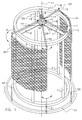
- the selection device shown in Figure 1 is intended for allowing a group of animals to pass from a first area to a second area.
- the selection device is provided with a frame disposed on the ground, constituted by upright bars 1, 2, 3, 4, 5 disposed on the ground and connected at the upper side by a connecting bar 6, which is circular in the embodiment shown. It will be obvious that, in an alternative embodiment, the connecting bar can also form a polygon.
- the circular connecting bar 6 is connected, via radial connecting elements 7, 8, 9, with a central boss 10 which is located around an imaginary central axis 11.
- An entrance opening of the selection device is located between two neighbouring upright bars 1, 2, 3, 4, 5.
- the entrance openings of the selection device are thus disposed around the central axis 11.
- Carrier arms 12, 13, 14, 15 extend radially from the boss 10.
- the carrier arms 12, 13, 14, 15 are connected with the central boss 10 via pivot axes 16, 17, 18, 19.
- Elongated carrier portions 20, 21, 22, 23, extending downwards, are fastened to the free ends of the carrier arms 12, 13, 14, 15.
- the carrier portions 20, 21, 22, 23 are included in a guiding manner in a guiding groove 24.
- the guiding groove 24 surrounds the upright bars 1, 2, 3, 4, 5.
- a cloth of fabric or plastic for forming a closing device 40, 41 which is capable of being rolled up for the entrance openings.
- At least one of the relevant carrier portions is provided with a rolling up mechanism known per se (not shown) for automatically rolling up or unrolling the cloth.
- a drive element 25 for example an electric motor or the like, drives the carrier arms 12, 13, 14, 15 for displacing the carrier portions 20, 21, 22, 23 relative to each other for increasing or decreasing the distance between the carrier portions. In this manner the cloth 40, 41 can be unrolled and/or rolled up.
- the drive element 25 is also capable of adjusting the position of the carrier arms relative to the entrance openings. In this manner, by displacing the carrier arms, it is possible to slide the cloth 40, 41 which is capable of being rolled up across the entrance openings, the cloth 40, 41 which is capable of being rolled up surrounding the frame at least partially.
- the closing device which is slidable across the entrance openings thus effects the gradual decrease of the size of the entrance opening and the closing of an entrance opening.
- an animal identification device 26 known per se is disposed on the frame and is suitable for identifying an animal that approaches an entrance opening.
- the animal identification device 26 supplies an identification signal to the drive element 25, as a result of which the latter is controlled with the aid of the identification signal.
- the selection device can also be operated independently of the animal identity.
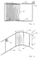
- Figure 2 shows a part of an alternative selection device, the slidable closing device comprising lamellas 27 which can be slid across the entrance opening by means of a drive element 28 via an upper guiding device 29 and a lower guiding device 30.
- the closing device comprises a sliding door 31.
- Figure 3 shows two of the partition elements, in the embodiment shown partition gates 35, 36, which separate the areas where the animals are allowed to walk about freely from each other.
- the sliding door 31 Via a drive motor 32 and guiding devices 33 and 34, the sliding door 31 is slidable across an entrance opening, the guiding devices being included partially in the partition gates in this embodiment.
- the slidable closing device is slidable across the entrance opening from top to bottom.
- the guiding devices are located on the sides of the closing device.
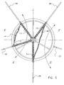
- Figure 4 is a schematic plan view of an embodiment of an assembly for keeping animals, such as cows.
- the assembly is provided with a number of areas I, II, III, IV, V, in which animals are allowed to move freely.
- the areas I, II, III, IV, V are separated from each other by partition elements 35, 36, 37, 38, 39, such as gates.
- Each area I, II, III, IV, V has a respective exit opening which, in the embodiment shown, coincides at least substantially with the entrance opening of the selection device.
- An exit opening of an area is thus in direct connection with a respective entrance opening.
- the connection can be effected via an additional path.
- the selection device shown in Figure 4 is analogous to that as shown in Figure 1.
- the carrier arms 12, 13, 14, 15 are positioned in such a way that there is formed a free passage from area I to area IV.
- the closing devices 40, 41 surround the relevant upright bars.
- the selection device is also suitable for confining a particular animal. For this purpose, when the animal identification device detects an animal to be confined, the carrier arms are displaced by the drive element in such a way that, when the animal is located in the inside of the selection device, all entrance openings are closed.
- the selection device is then capable of supplying via the assembly, with the aid of a transmitter or the like, a signal to the manager that the relevant animal has been confined. Analogously, with the aid of the animal identification device, it is possible to provide selective passage through the selection device.
- the cloths do not surround the frame (or a frame with upright bars is not present). In this case, the cloths are pulled tight. As shown, in this manner a connection between areas l and IV and areas II en III can be obtained simultaneously.
- the selection device may be provided, for example, with a clamp protection known per se for the slidable closing devices.
- deterring elements such as for example electrified wire, in the closing device, in order that animals will not kick against a closed closing device to still get access to the selection device.
Landscapes
- Life Sciences & Earth Sciences (AREA)
- Environmental Sciences (AREA)
- Zoology (AREA)
- Animal Husbandry (AREA)
- Biodiversity & Conservation Biology (AREA)
- Housing For Livestock And Birds (AREA)
- Warehouses Or Storage Devices (AREA)
Abstract
Description
- The invention relates to an assembly for keeping animals, such as cows, according to the preamble of claim 1.
- Such an assembly is known from
EP-A-0898880 . In this known assembly the entrance openings are closed by pivoting gates. The known assembly is used, for example, for keeping animals that have been milked and have not been milked, for example cows, belonging to the same group, separate from each other. - The invention aims at providing an alternative assembly.
- For this purpose, according to the invention, an assembly for keeping animals, such as cows, of the type mentioned in the preamble comprises the features of the characterizing part of claim 1. Owing to the fact that there is used a closing device which is slidable by means of a drive element for reducing the size of the entrance opening and for closing an entrance opening, it is possible to design the selection device more compactly and more multifunctionally than in the case of the known pivoting gates.
- It is pointed out here that a closing device which is slidable by means of a drive element, such as for example a sliding door, is known per se. The invention focuses on the use of such a closing device which is slidable by means of a drive element for controlling animal traffic between a first area where the animals are allowed to move freely and a second area where the animals are allowed to move freely.
- The slidable closing device preferably comprises a guide element, and the assembly is preferably provided with a guiding device for guiding the guide element in a sliding manner. In this manner the closing device can be driven in an accurate and reliable manner for closing the entrance opening.
- Depending on the direction in which the closing device slides across the entrance opening, the guide element is fitted to an upper side and/or to a lower side of the closing device, or to an upright side of the closing device, preferably on two opposite sides of guide elements.
- For the purpose of obtaining a compact selection device, the guiding device is partially included in a partition gate.
- Although it is possible to use a sliding closing device for closing more than one entrance opening, for controlling animal traffic, the assembly preferably comprises per entrance opening a respective closing device.
- If the assembly comprises an animal identification device for identifying an animal and for supplying an identification signal, the drive element being controlled with the aid of the identification signal, an entrance opening can be closed or released depending on the individual animal.
- In an embodiment of an assembly according to the invention, the closing device comprises lamellas. Alternatively, the closing device comprises a sliding door.
- Alternatively, the closing device is provided with a closing element which is capable of being rolled up, such as a cloth of fabric or plastic, with two elongated carrier portions, an end of the closing device which is capable of being rolled up being fastened to each carrier portion, the drive element being suitable for displacing the carrier portions relative to each other for increasing or decreasing the distance between the carrier portions, and with a rolling up mechanism for automatically rolling up or unrolling the closing element. Such a rolling up mechanism is known per se, for example with sun blinds and roller blinds.
- If the entrance openings of the selection device are disposed around a central axis, it is advantageous if each carrier portion is fastened to an arm which extends radially outwards from the central axis, the drive element being suitable for causing the arm to pivot about the central axis for causing the closing element which is capable of being rolled up to slide across the entrance opening. The selection device is preferably provided with a frame which is disposed on the ground, the closing element which is capable of being rolled up surrounding the frame at least partially.
- The invention also relates to a selection device for allowing animals to pass from a first area to a second area, which selection device is suitable for use in an assembly as claimed in any one of the preceding claims, the selection device having a number of entrance openings, the number of entrance openings corresponding with the number of exit openings, and an exit opening being in connection with a respective entrance opening, characterized in that the selection device is provided with at least one closing device which is slidable by means of a drive element for closing an entrance opening.
- The features of the preferred embodiments described in the subclaims of the assembly according to the invention also apply, as far as possible, to the selection device according to the invention.
- Hereinafter the invention will be explained in further detail on the basis of non-restricting exemplary embodiments with reference to the accompanying drawings, in which:
- Figure 1 is a perspective view of an embodiment of a selection device according to the invention;
- Figure 2 is a front view of an alternative embodiment of a selection device according to the invention;
- Figure 3 is a perspective view of a further alternative embodiment of a selection device according to the invention, in which a part of the guiding device is disposed in a partition element;
- Figure 4 is a schematic plan view of an assembly according to the invention with a selection device comprising a frame, and
- Figure 5 is a schematic plan view of an alternative assembly.
- The selection device shown in Figure 1 is intended for allowing a group of animals to pass from a first area to a second area. The selection device is provided with a frame disposed on the ground, constituted by
upright bars bar 6, which is circular in the embodiment shown. It will be obvious that, in an alternative embodiment, the connecting bar can also form a polygon. The circular connectingbar 6 is connected, via radial connectingelements central boss 10 which is located around an imaginarycentral axis 11. - An entrance opening of the selection device is located between two neighbouring
upright bars central axis 11. - Carrier arms 12, 13, 14, 15 extend radially from the
boss 10. Thecarrier arms central boss 10 viapivot axes carrier portions carrier arms carrier portions groove 24. The guidinggroove 24 surrounds theupright bars - Between the two
carrier portions carrier portions closing device - A
drive element 25, for example an electric motor or the like, drives thecarrier arms carrier portions cloth drive element 25 is also capable of adjusting the position of the carrier arms relative to the entrance openings. In this manner, by displacing the carrier arms, it is possible to slide thecloth cloth - In the embodiment shown, an
animal identification device 26 known per se is disposed on the frame and is suitable for identifying an animal that approaches an entrance opening. Theanimal identification device 26 supplies an identification signal to thedrive element 25, as a result of which the latter is controlled with the aid of the identification signal. It will be obvious that the selection device can also be operated independently of the animal identity. - Figure 2 shows a part of an alternative selection device, the slidable closing
device comprising lamellas 27 which can be slid across the entrance opening by means of adrive element 28 via an upper guidingdevice 29 and a lower guidingdevice 30. - In Figure 3 the closing device comprises a sliding
door 31. Figure 3 shows two of the partition elements, in the embodiment shownpartition gates drive motor 32 and guidingdevices door 31 is slidable across an entrance opening, the guiding devices being included partially in the partition gates in this embodiment. - It will be obvious that, in alternative embodiments, the slidable closing device is slidable across the entrance opening from top to bottom. In this case, the guiding devices are located on the sides of the closing device.
- Figure 4 is a schematic plan view of an embodiment of an assembly for keeping animals, such as cows. The assembly is provided with a number of areas I, II, III, IV, V, in which animals are allowed to move freely. The areas I, II, III, IV, V are separated from each other by
partition elements - In the situation shown in Figure 4, the
carrier arms closing devices - In the embodiment shown in Figure 5, the cloths do not surround the frame (or a frame with upright bars is not present). In this case, the cloths are pulled tight. As shown, in this manner a connection between areas l and IV and areas II en III can be obtained simultaneously.
- It will be obvious that the invention is not limited to the embodiments shown. The selection device may be provided, for example, with a clamp protection known per se for the slidable closing devices. Furthermore, it is possible to include particular deterring elements, such as for example electrified wire, in the closing device, in order that animals will not kick against a closed closing device to still get access to the selection device.
Claims (15)
- An assembly for keeping animals, such as cows, which assembly is provided with a number of areas where animals are allowed to move freely and with a selection device for allowing animals to pass from a first area to a second area, the areas being separated from each other by partition elements (35, 36, 37, 38, 39), such as gates, each area having a respective exit opening, the selection device having a number of entrance openings, the number of entrance openings corresponding with the number of exit openings, and an exit opening being in connection with a respective entrance opening, characterized in that the assembly is provided with at least one closing device which is slidable by means of a drive element for reducing the size of the entrance opening and for closing an entrance opening.
- An assembly as claimed in claim 1, characterized in that the slidable closing device comprises a guide element, and in that the assembly is provided with a guiding device (33, 34) for guiding the guide element in a sliding manner.
- An assembly as claimed in claim 2, characterized in that the guide element is fitted to an upper side of the closing device.
- An assembly as claimed in claim 2 or 3, characterized in that the guide element is fitted to a lower side of the closing device.
- An assembly as claimed in claim 2, 3 or 4, characterized in that the guide element is fitted to an upright side of the closing device.
- An assembly as claimed in claim 2, 3, 4 or 5, characterized in that the closing device is provided with guide elements on two opposite sides.
- An assembly as claimed in any one of claims 2 to 6, characterized in that the guiding device (33, 34) is partially included in a partition element (35, 36, 37, 38, 39).
- An assembly as claimed in any one of the preceding claims, characterized in that the assembly comprises per entrance opening a respective closing device.
- An assembly as claimed in any one of the preceding claims, characterized in that the assembly comprises an animal identification device (26) for identifying an animal and for supplying an identification signal, the drive element (25, 28, 32) being controlled with the aid of the identification signal.
- An assembly as claimed in any one of the preceding claims, characterized in that the closing device comprises lamellas (27).
- An assembly as claimed in any one of claims 1 to 9, characterized in that the closing device comprises a sliding door (31).
- An assembly as claimed in any one of claims 1 to 9, characterized in that the closing device is provided with a closing element which is capable of being rolled up, such as a cloth (40, 41) of fabric or plastic, with two elongated carrier portions (20, 21; 22, 23), an end of the closing device which is capable of being rolled up being fastened to each carrier portion (20, 21; 22, 23), the drive element being suitable for displacing the carrier portions (20, 21; 22, 23) relative to each other for increasing or decreasing the distance between the carrier portions, and with a rolling up mechanism for automatically rolling up or unrolling the closing element (40, 41).
- An assembly as claimed in claim 12, characterized in that the entrance openings of the selection device are disposed around a central axis (11), in that each carrier portion is fastened to an arm (12, 13; 14, 15) which extends radially outwards from the central axis (11), and in that the drive element (25, 28, 32) is suitable for causing the arm to pivot about the central axis (11) for causing the closing element (40, 41) which is capable of being rolled up to slide across the entrance opening.
- An assembly as claimed in claim 12 or 13, characterized in that the selection device is provided with a frame which is disposed on the ground, the closing element which is capable of being rolled up surrounding the frame at least partially.
- A selection device for allowing animals to pass from a first area to a second area, which selection device is suitable for use in an assembly as claimed in any one of the preceding claims, the selection device having a number of entrance openings, the number of entrance openings corresponding with the number of exit openings, and an exit opening being in connection with a respective entrance opening, characterized in that the selection device is provided with at least one closing device which is slidable by means of a drive element (25, 28, 32) for closing an entrance opening.
Applications Claiming Priority (1)
| Application Number | Priority Date | Filing Date | Title |
|---|---|---|---|
| NL1028704A NL1028704C2 (en) | 2005-04-06 | 2005-04-06 | An animal-keeping assembly and a selection device for allowing animals to pass from a first area to a second area. |
Publications (2)
| Publication Number | Publication Date |
|---|---|
| EP1709866A1 true EP1709866A1 (en) | 2006-10-11 |
| EP1709866B1 EP1709866B1 (en) | 2009-05-13 |
Family
ID=35197278
Family Applications (1)
| Application Number | Title | Priority Date | Filing Date |
|---|---|---|---|
| EP06075566A Not-in-force EP1709866B1 (en) | 2005-04-06 | 2006-03-09 | An assembly for keeping animals and a selection device for allowing animals to pass from a first area to a second area |
Country Status (5)
| Country | Link |
|---|---|
| EP (1) | EP1709866B1 (en) |
| AT (1) | ATE431071T1 (en) |
| DE (1) | DE602006006743D1 (en) |
| DK (1) | DK1709866T3 (en) |
| NL (1) | NL1028704C2 (en) |
Citations (8)
| Publication number | Priority date | Publication date | Assignee | Title |
|---|---|---|---|---|
| US4136641A (en) | 1977-03-21 | 1979-01-30 | Hoffman Herbert F | Livestock sorting gate |
| US4261297A (en) * | 1978-05-17 | 1981-04-14 | Eric Van Maarion | Animal processing system and cutting gate |
| US4328643A (en) * | 1979-07-26 | 1982-05-11 | Bell Edward J | Gate assembly |
| US4617876A (en) * | 1984-11-28 | 1986-10-21 | Hayes Norman J | Animal identification and control system |
| US5230299A (en) * | 1992-07-31 | 1993-07-27 | Norbco Inc. | Telescoping entry gate for milking parlor |
| CA2148680A1 (en) * | 1995-05-04 | 1996-11-05 | Peggy Dopheide | Screen door |
| EP0898880A1 (en) | 1997-08-28 | 1999-03-03 | Maasland N.V. | An implement for passing in predetermined directions of separate groups of animals from one area to an other |
| NL1013208C2 (en) | 1999-10-04 | 2001-04-05 | Skiold Nederland B V | Measurement sluice for fattened cattle has one closable inlet providing access to measurement chamber containing at least one measurement device for determining at least one magnitude |
Family Cites Families (1)
| Publication number | Priority date | Publication date | Assignee | Title |
|---|---|---|---|---|
| US3894516A (en) * | 1973-05-03 | 1975-07-15 | Michael J Schaefer | Animal sorting gate |
-
2005
- 2005-04-06 NL NL1028704A patent/NL1028704C2/en not_active IP Right Cessation
-
2006
- 2006-03-09 AT AT06075566T patent/ATE431071T1/en not_active IP Right Cessation
- 2006-03-09 DE DE602006006743T patent/DE602006006743D1/en active Active
- 2006-03-09 DK DK06075566T patent/DK1709866T3/en active
- 2006-03-09 EP EP06075566A patent/EP1709866B1/en not_active Not-in-force
Patent Citations (8)
| Publication number | Priority date | Publication date | Assignee | Title |
|---|---|---|---|---|
| US4136641A (en) | 1977-03-21 | 1979-01-30 | Hoffman Herbert F | Livestock sorting gate |
| US4261297A (en) * | 1978-05-17 | 1981-04-14 | Eric Van Maarion | Animal processing system and cutting gate |
| US4328643A (en) * | 1979-07-26 | 1982-05-11 | Bell Edward J | Gate assembly |
| US4617876A (en) * | 1984-11-28 | 1986-10-21 | Hayes Norman J | Animal identification and control system |
| US5230299A (en) * | 1992-07-31 | 1993-07-27 | Norbco Inc. | Telescoping entry gate for milking parlor |
| CA2148680A1 (en) * | 1995-05-04 | 1996-11-05 | Peggy Dopheide | Screen door |
| EP0898880A1 (en) | 1997-08-28 | 1999-03-03 | Maasland N.V. | An implement for passing in predetermined directions of separate groups of animals from one area to an other |
| NL1013208C2 (en) | 1999-10-04 | 2001-04-05 | Skiold Nederland B V | Measurement sluice for fattened cattle has one closable inlet providing access to measurement chamber containing at least one measurement device for determining at least one magnitude |
Also Published As
| Publication number | Publication date |
|---|---|
| NL1028704C2 (en) | 2006-10-09 |
| EP1709866B1 (en) | 2009-05-13 |
| ATE431071T1 (en) | 2009-05-15 |
| DE602006006743D1 (en) | 2009-06-25 |
| DK1709866T3 (en) | 2009-08-31 |
Similar Documents
| Publication | Publication Date | Title |
|---|---|---|
| DE69637425T2 (en) | Sealable cover | |
| US20100064572A1 (en) | Animal trap | |
| DE69729838T2 (en) | Automatic door assembly | |
| EP2098112B1 (en) | Assembly for and method of grazing | |
| US8100091B2 (en) | Livestock moving system and method | |
| US6481156B1 (en) | Kennel door apparatus | |
| EP1709866A1 (en) | An assembly for keeping animals and a selection device for allowing animals to pass from a first area to a second area | |
| US6427632B1 (en) | Remote controlled gate assembly | |
| US5178199A (en) | Bi-parting shutter system | |
| CN111801008B (en) | Milking device | |
| PL190689B1 (en) | Wall-mounted ventilation unit | |
| HUE030480T2 (en) | Roller shutters usable as a Venetian blind reinforcement with pivoting rods | |
| EP0350558B1 (en) | Milking device for cows and buffalo-cows with comb-like arrangement of the stations. | |
| ES2275482T3 (en) | DEVICE OF WINDING BLIND, DIVIDED IN TWO PARTS, WITH VARIABLE WINDOW. | |
| US6394170B1 (en) | Operating structure for vertically collecting/shutting a blind | |
| EP0092625B1 (en) | Enclosure for accommodating animals, such as a battery of cages | |
| JP3256156B2 (en) | Blind operation mechanism | |
| KR101491733B1 (en) | Apparatus for opening and shutting roof | |
| US6035921A (en) | Gate control apparatus | |
| EP0943774B1 (en) | Actuator with adjustable stroke | |
| EP0638704A2 (en) | Device for preventing from insect penetration through a window | |
| ES2292736T3 (en) | OCULTATION DEVICE FOR CLOSURES. | |
| ES2314482T3 (en) | AUTOBLOCANT DEVICE WITH SIDE GUIDES, USED IN CURTAINS. | |
| KR100406400B1 (en) | Vertical blinds | |
| JP4229665B2 (en) | Elevator door equipment |
Legal Events
| Date | Code | Title | Description |
|---|---|---|---|
| PUAI | Public reference made under article 153(3) epc to a published international application that has entered the european phase |
Free format text: ORIGINAL CODE: 0009012 |
|
| AK | Designated contracting states |
Kind code of ref document: A1 Designated state(s): AT BE BG CH CY CZ DE DK EE ES FI FR GB GR HU IE IS IT LI LT LU LV MC NL PL PT RO SE SI SK TR |
|
| AX | Request for extension of the european patent |
Extension state: AL BA HR MK YU |
|
| 17P | Request for examination filed |
Effective date: 20070111 |
|
| 17Q | First examination report despatched |
Effective date: 20070222 |
|
| AKX | Designation fees paid |
Designated state(s): AT BE BG CH CY CZ DE DK EE ES FI FR GB GR HU IE IS IT LI LT LU LV MC NL PL PT RO SE SI SK TR |
|
| GRAP | Despatch of communication of intention to grant a patent |
Free format text: ORIGINAL CODE: EPIDOSNIGR1 |
|
| GRAS | Grant fee paid |
Free format text: ORIGINAL CODE: EPIDOSNIGR3 |
|
| GRAA | (expected) grant |
Free format text: ORIGINAL CODE: 0009210 |
|
| AK | Designated contracting states |
Kind code of ref document: B1 Designated state(s): AT BE BG CH CY CZ DE DK EE ES FI FR GB GR HU IE IS IT LI LT LU LV MC NL PL PT RO SE SI SK TR |
|
| REG | Reference to a national code |
Ref country code: GB Ref legal event code: FG4D |
|
| REG | Reference to a national code |
Ref country code: CH Ref legal event code: EP |
|
| REG | Reference to a national code |
Ref country code: IE Ref legal event code: FG4D |
|
| REF | Corresponds to: |
Ref document number: 602006006743 Country of ref document: DE Date of ref document: 20090625 Kind code of ref document: P |
|
| REG | Reference to a national code |
Ref country code: SE Ref legal event code: TRGR |
|
| REG | Reference to a national code |
Ref country code: DK Ref legal event code: T3 |
|
| PG25 | Lapsed in a contracting state [announced via postgrant information from national office to epo] |
Ref country code: PT Free format text: LAPSE BECAUSE OF FAILURE TO SUBMIT A TRANSLATION OF THE DESCRIPTION OR TO PAY THE FEE WITHIN THE PRESCRIBED TIME-LIMIT Effective date: 20090913 Ref country code: AT Free format text: LAPSE BECAUSE OF FAILURE TO SUBMIT A TRANSLATION OF THE DESCRIPTION OR TO PAY THE FEE WITHIN THE PRESCRIBED TIME-LIMIT Effective date: 20090513 Ref country code: LT Free format text: LAPSE BECAUSE OF FAILURE TO SUBMIT A TRANSLATION OF THE DESCRIPTION OR TO PAY THE FEE WITHIN THE PRESCRIBED TIME-LIMIT Effective date: 20090513 Ref country code: FI Free format text: LAPSE BECAUSE OF FAILURE TO SUBMIT A TRANSLATION OF THE DESCRIPTION OR TO PAY THE FEE WITHIN THE PRESCRIBED TIME-LIMIT Effective date: 20090513 Ref country code: ES Free format text: LAPSE BECAUSE OF FAILURE TO SUBMIT A TRANSLATION OF THE DESCRIPTION OR TO PAY THE FEE WITHIN THE PRESCRIBED TIME-LIMIT Effective date: 20090824 |
|
| PG25 | Lapsed in a contracting state [announced via postgrant information from national office to epo] |
Ref country code: PL Free format text: LAPSE BECAUSE OF FAILURE TO SUBMIT A TRANSLATION OF THE DESCRIPTION OR TO PAY THE FEE WITHIN THE PRESCRIBED TIME-LIMIT Effective date: 20090513 Ref country code: LV Free format text: LAPSE BECAUSE OF FAILURE TO SUBMIT A TRANSLATION OF THE DESCRIPTION OR TO PAY THE FEE WITHIN THE PRESCRIBED TIME-LIMIT Effective date: 20090513 Ref country code: SI Free format text: LAPSE BECAUSE OF FAILURE TO SUBMIT A TRANSLATION OF THE DESCRIPTION OR TO PAY THE FEE WITHIN THE PRESCRIBED TIME-LIMIT Effective date: 20090513 Ref country code: IS Free format text: LAPSE BECAUSE OF FAILURE TO SUBMIT A TRANSLATION OF THE DESCRIPTION OR TO PAY THE FEE WITHIN THE PRESCRIBED TIME-LIMIT Effective date: 20090913 |
|
| PG25 | Lapsed in a contracting state [announced via postgrant information from national office to epo] |
Ref country code: EE Free format text: LAPSE BECAUSE OF FAILURE TO SUBMIT A TRANSLATION OF THE DESCRIPTION OR TO PAY THE FEE WITHIN THE PRESCRIBED TIME-LIMIT Effective date: 20090513 Ref country code: RO Free format text: LAPSE BECAUSE OF FAILURE TO SUBMIT A TRANSLATION OF THE DESCRIPTION OR TO PAY THE FEE WITHIN THE PRESCRIBED TIME-LIMIT Effective date: 20090513 Ref country code: CZ Free format text: LAPSE BECAUSE OF FAILURE TO SUBMIT A TRANSLATION OF THE DESCRIPTION OR TO PAY THE FEE WITHIN THE PRESCRIBED TIME-LIMIT Effective date: 20090513 |
|
| PG25 | Lapsed in a contracting state [announced via postgrant information from national office to epo] |
Ref country code: SK Free format text: LAPSE BECAUSE OF FAILURE TO SUBMIT A TRANSLATION OF THE DESCRIPTION OR TO PAY THE FEE WITHIN THE PRESCRIBED TIME-LIMIT Effective date: 20090513 Ref country code: BE Free format text: LAPSE BECAUSE OF FAILURE TO SUBMIT A TRANSLATION OF THE DESCRIPTION OR TO PAY THE FEE WITHIN THE PRESCRIBED TIME-LIMIT Effective date: 20090513 |
|
| PLBE | No opposition filed within time limit |
Free format text: ORIGINAL CODE: 0009261 |
|
| STAA | Information on the status of an ep patent application or granted ep patent |
Free format text: STATUS: NO OPPOSITION FILED WITHIN TIME LIMIT |
|
| PG25 | Lapsed in a contracting state [announced via postgrant information from national office to epo] |
Ref country code: BG Free format text: LAPSE BECAUSE OF FAILURE TO SUBMIT A TRANSLATION OF THE DESCRIPTION OR TO PAY THE FEE WITHIN THE PRESCRIBED TIME-LIMIT Effective date: 20090813 |
|
| 26N | No opposition filed |
Effective date: 20100216 |
|
| PG25 | Lapsed in a contracting state [announced via postgrant information from national office to epo] |
Ref country code: GR Free format text: LAPSE BECAUSE OF FAILURE TO SUBMIT A TRANSLATION OF THE DESCRIPTION OR TO PAY THE FEE WITHIN THE PRESCRIBED TIME-LIMIT Effective date: 20090814 Ref country code: MC Free format text: LAPSE BECAUSE OF NON-PAYMENT OF DUE FEES Effective date: 20100331 |
|
| REG | Reference to a national code |
Ref country code: CH Ref legal event code: PL |
|
| PG25 | Lapsed in a contracting state [announced via postgrant information from national office to epo] |
Ref country code: IE Free format text: LAPSE BECAUSE OF NON-PAYMENT OF DUE FEES Effective date: 20100309 |
|
| PG25 | Lapsed in a contracting state [announced via postgrant information from national office to epo] |
Ref country code: CH Free format text: LAPSE BECAUSE OF NON-PAYMENT OF DUE FEES Effective date: 20100331 Ref country code: LI Free format text: LAPSE BECAUSE OF NON-PAYMENT OF DUE FEES Effective date: 20100331 |
|
| PG25 | Lapsed in a contracting state [announced via postgrant information from national office to epo] |
Ref country code: IT Free format text: LAPSE BECAUSE OF FAILURE TO SUBMIT A TRANSLATION OF THE DESCRIPTION OR TO PAY THE FEE WITHIN THE PRESCRIBED TIME-LIMIT Effective date: 20090513 |
|
| PG25 | Lapsed in a contracting state [announced via postgrant information from national office to epo] |
Ref country code: CY Free format text: LAPSE BECAUSE OF FAILURE TO SUBMIT A TRANSLATION OF THE DESCRIPTION OR TO PAY THE FEE WITHIN THE PRESCRIBED TIME-LIMIT Effective date: 20090513 |
|
| PG25 | Lapsed in a contracting state [announced via postgrant information from national office to epo] |
Ref country code: HU Free format text: LAPSE BECAUSE OF FAILURE TO SUBMIT A TRANSLATION OF THE DESCRIPTION OR TO PAY THE FEE WITHIN THE PRESCRIBED TIME-LIMIT Effective date: 20091114 Ref country code: LU Free format text: LAPSE BECAUSE OF NON-PAYMENT OF DUE FEES Effective date: 20100309 |
|
| PG25 | Lapsed in a contracting state [announced via postgrant information from national office to epo] |
Ref country code: TR Free format text: LAPSE BECAUSE OF FAILURE TO SUBMIT A TRANSLATION OF THE DESCRIPTION OR TO PAY THE FEE WITHIN THE PRESCRIBED TIME-LIMIT Effective date: 20090513 |
|
| PGFP | Annual fee paid to national office [announced via postgrant information from national office to epo] |
Ref country code: DK Payment date: 20140325 Year of fee payment: 9 |
|
| PGFP | Annual fee paid to national office [announced via postgrant information from national office to epo] |
Ref country code: GB Payment date: 20140327 Year of fee payment: 9 |
|
| REG | Reference to a national code |
Ref country code: FR Ref legal event code: PLFP Year of fee payment: 10 |
|
| PGFP | Annual fee paid to national office [announced via postgrant information from national office to epo] |
Ref country code: NL Payment date: 20150326 Year of fee payment: 10 Ref country code: DE Payment date: 20150327 Year of fee payment: 10 |
|
| PGFP | Annual fee paid to national office [announced via postgrant information from national office to epo] |
Ref country code: SE Payment date: 20150327 Year of fee payment: 10 Ref country code: FR Payment date: 20150317 Year of fee payment: 10 |
|
| REG | Reference to a national code |
Ref country code: DK Ref legal event code: EBP Effective date: 20150331 |
|
| GBPC | Gb: european patent ceased through non-payment of renewal fee |
Effective date: 20150309 |
|
| PG25 | Lapsed in a contracting state [announced via postgrant information from national office to epo] |
Ref country code: GB Free format text: LAPSE BECAUSE OF NON-PAYMENT OF DUE FEES Effective date: 20150309 |
|
| PG25 | Lapsed in a contracting state [announced via postgrant information from national office to epo] |
Ref country code: DK Free format text: LAPSE BECAUSE OF NON-PAYMENT OF DUE FEES Effective date: 20150331 |
|
| REG | Reference to a national code |
Ref country code: DE Ref legal event code: R119 Ref document number: 602006006743 Country of ref document: DE |
|
| REG | Reference to a national code |
Ref country code: SE Ref legal event code: EUG |
|
| REG | Reference to a national code |
Ref country code: NL Ref legal event code: MM Effective date: 20160401 |
|
| PG25 | Lapsed in a contracting state [announced via postgrant information from national office to epo] |
Ref country code: SE Free format text: LAPSE BECAUSE OF NON-PAYMENT OF DUE FEES Effective date: 20160310 |
|
| REG | Reference to a national code |
Ref country code: FR Ref legal event code: ST Effective date: 20161130 |
|
| PG25 | Lapsed in a contracting state [announced via postgrant information from national office to epo] |
Ref country code: NL Free format text: LAPSE BECAUSE OF NON-PAYMENT OF DUE FEES Effective date: 20160401 Ref country code: FR Free format text: LAPSE BECAUSE OF NON-PAYMENT OF DUE FEES Effective date: 20160331 Ref country code: DE Free format text: LAPSE BECAUSE OF NON-PAYMENT OF DUE FEES Effective date: 20161001 |