EP1706773B1 - Night vision system for motor vehicles, comprising a partial optical filter - Google Patents
Night vision system for motor vehicles, comprising a partial optical filter Download PDFInfo
- Publication number
- EP1706773B1 EP1706773B1 EP04820035A EP04820035A EP1706773B1 EP 1706773 B1 EP1706773 B1 EP 1706773B1 EP 04820035 A EP04820035 A EP 04820035A EP 04820035 A EP04820035 A EP 04820035A EP 1706773 B1 EP1706773 B1 EP 1706773B1
- Authority
- EP
- European Patent Office
- Prior art keywords
- night vision
- image sensor
- vision system
- radiation
- filter
- Prior art date
- Legal status (The legal status is an assumption and is not a legal conclusion. Google has not performed a legal analysis and makes no representation as to the accuracy of the status listed.)
- Expired - Fee Related
Links
- 230000004297 night vision Effects 0.000 title claims description 39
- 230000003287 optical effect Effects 0.000 title description 13
- 230000005855 radiation Effects 0.000 claims description 31
- 230000001419 dependent effect Effects 0.000 claims description 17
- 230000005540 biological transmission Effects 0.000 claims description 10
- 238000000576 coating method Methods 0.000 claims description 9
- 239000011248 coating agent Substances 0.000 claims description 8
- 230000002238 attenuated effect Effects 0.000 claims description 4
- 230000001629 suppression Effects 0.000 claims description 3
- 230000000694 effects Effects 0.000 claims description 2
- 230000005670 electromagnetic radiation Effects 0.000 claims description 2
- 239000011521 glass Substances 0.000 claims description 2
- 238000001228 spectrum Methods 0.000 claims description 2
- 230000001681 protective effect Effects 0.000 claims 1
- 230000003595 spectral effect Effects 0.000 description 8
- 238000005286 illumination Methods 0.000 description 5
- 230000006872 improvement Effects 0.000 description 5
- 238000010586 diagram Methods 0.000 description 4
- 238000013461 design Methods 0.000 description 3
- 238000001514 detection method Methods 0.000 description 3
- 230000010287 polarization Effects 0.000 description 3
- 238000012805 post-processing Methods 0.000 description 3
- 238000012545 processing Methods 0.000 description 3
- 238000002834 transmittance Methods 0.000 description 3
- 238000010521 absorption reaction Methods 0.000 description 2
- 230000000903 blocking effect Effects 0.000 description 2
- 238000011161 development Methods 0.000 description 2
- 230000018109 developmental process Effects 0.000 description 2
- 229910052736 halogen Inorganic materials 0.000 description 2
- 150000002367 halogens Chemical class 0.000 description 2
- 238000003384 imaging method Methods 0.000 description 2
- 239000000463 material Substances 0.000 description 2
- 238000000034 method Methods 0.000 description 2
- 230000035945 sensitivity Effects 0.000 description 2
- 238000000926 separation method Methods 0.000 description 2
- 230000004913 activation Effects 0.000 description 1
- 230000006978 adaptation Effects 0.000 description 1
- 239000010426 asphalt Substances 0.000 description 1
- 230000009286 beneficial effect Effects 0.000 description 1
- 230000000295 complement effect Effects 0.000 description 1
- 239000006059 cover glass Substances 0.000 description 1
- 238000013016 damping Methods 0.000 description 1
- 238000005516 engineering process Methods 0.000 description 1
- 230000004438 eyesight Effects 0.000 description 1
- 210000003608 fece Anatomy 0.000 description 1
- 238000002329 infrared spectrum Methods 0.000 description 1
- 230000002452 interceptive effect Effects 0.000 description 1
- 230000035699 permeability Effects 0.000 description 1
- 230000008569 process Effects 0.000 description 1
- 239000004065 semiconductor Substances 0.000 description 1
- 238000001429 visible spectrum Methods 0.000 description 1
- 238000012800 visualization Methods 0.000 description 1
Images

Classifications
-
- B—PERFORMING OPERATIONS; TRANSPORTING
- B60—VEHICLES IN GENERAL
- B60R—VEHICLES, VEHICLE FITTINGS, OR VEHICLE PARTS, NOT OTHERWISE PROVIDED FOR
- B60R1/00—Optical viewing arrangements; Real-time viewing arrangements for drivers or passengers using optical image capturing systems, e.g. cameras or video systems specially adapted for use in or on vehicles
- B60R1/20—Real-time viewing arrangements for drivers or passengers using optical image capturing systems, e.g. cameras or video systems specially adapted for use in or on vehicles
- B60R1/30—Real-time viewing arrangements for drivers or passengers using optical image capturing systems, e.g. cameras or video systems specially adapted for use in or on vehicles providing vision in the non-visible spectrum, e.g. night or infrared vision
-
- B—PERFORMING OPERATIONS; TRANSPORTING
- B60—VEHICLES IN GENERAL
- B60R—VEHICLES, VEHICLE FITTINGS, OR VEHICLE PARTS, NOT OTHERWISE PROVIDED FOR
- B60R1/00—Optical viewing arrangements; Real-time viewing arrangements for drivers or passengers using optical image capturing systems, e.g. cameras or video systems specially adapted for use in or on vehicles
- B60R1/20—Real-time viewing arrangements for drivers or passengers using optical image capturing systems, e.g. cameras or video systems specially adapted for use in or on vehicles
- B60R1/22—Real-time viewing arrangements for drivers or passengers using optical image capturing systems, e.g. cameras or video systems specially adapted for use in or on vehicles for viewing an area outside the vehicle, e.g. the exterior of the vehicle
- B60R1/23—Real-time viewing arrangements for drivers or passengers using optical image capturing systems, e.g. cameras or video systems specially adapted for use in or on vehicles for viewing an area outside the vehicle, e.g. the exterior of the vehicle with a predetermined field of view
- B60R1/24—Real-time viewing arrangements for drivers or passengers using optical image capturing systems, e.g. cameras or video systems specially adapted for use in or on vehicles for viewing an area outside the vehicle, e.g. the exterior of the vehicle with a predetermined field of view in front of the vehicle
-
- G—PHYSICS
- G01—MEASURING; TESTING
- G01S—RADIO DIRECTION-FINDING; RADIO NAVIGATION; DETERMINING DISTANCE OR VELOCITY BY USE OF RADIO WAVES; LOCATING OR PRESENCE-DETECTING BY USE OF THE REFLECTION OR RERADIATION OF RADIO WAVES; ANALOGOUS ARRANGEMENTS USING OTHER WAVES
- G01S17/00—Systems using the reflection or reradiation of electromagnetic waves other than radio waves, e.g. lidar systems
- G01S17/88—Lidar systems specially adapted for specific applications
- G01S17/89—Lidar systems specially adapted for specific applications for mapping or imaging
-
- G—PHYSICS
- G01—MEASURING; TESTING
- G01S—RADIO DIRECTION-FINDING; RADIO NAVIGATION; DETERMINING DISTANCE OR VELOCITY BY USE OF RADIO WAVES; LOCATING OR PRESENCE-DETECTING BY USE OF THE REFLECTION OR RERADIATION OF RADIO WAVES; ANALOGOUS ARRANGEMENTS USING OTHER WAVES
- G01S17/00—Systems using the reflection or reradiation of electromagnetic waves other than radio waves, e.g. lidar systems
- G01S17/88—Lidar systems specially adapted for specific applications
- G01S17/93—Lidar systems specially adapted for specific applications for anti-collision purposes
- G01S17/931—Lidar systems specially adapted for specific applications for anti-collision purposes of land vehicles
-
- G—PHYSICS
- G01—MEASURING; TESTING
- G01S—RADIO DIRECTION-FINDING; RADIO NAVIGATION; DETERMINING DISTANCE OR VELOCITY BY USE OF RADIO WAVES; LOCATING OR PRESENCE-DETECTING BY USE OF THE REFLECTION OR RERADIATION OF RADIO WAVES; ANALOGOUS ARRANGEMENTS USING OTHER WAVES
- G01S7/00—Details of systems according to groups G01S13/00, G01S15/00, G01S17/00
- G01S7/48—Details of systems according to groups G01S13/00, G01S15/00, G01S17/00 of systems according to group G01S17/00
- G01S7/481—Constructional features, e.g. arrangements of optical elements
- G01S7/4811—Constructional features, e.g. arrangements of optical elements common to transmitter and receiver
- G01S7/4813—Housing arrangements
-
- G—PHYSICS
- G02—OPTICS
- G02B—OPTICAL ELEMENTS, SYSTEMS OR APPARATUS
- G02B13/00—Optical objectives specially designed for the purposes specified below
- G02B13/14—Optical objectives specially designed for the purposes specified below for use with infrared or ultraviolet radiation
-
- G—PHYSICS
- G02—OPTICS
- G02B—OPTICAL ELEMENTS, SYSTEMS OR APPARATUS
- G02B5/00—Optical elements other than lenses
- G02B5/20—Filters
- G02B5/208—Filters for use with infrared or ultraviolet radiation, e.g. for separating visible light from infrared and/or ultraviolet radiation
-
- H—ELECTRICITY
- H04—ELECTRIC COMMUNICATION TECHNIQUE
- H04N—PICTORIAL COMMUNICATION, e.g. TELEVISION
- H04N5/00—Details of television systems
- H04N5/30—Transforming light or analogous information into electric information
- H04N5/33—Transforming infrared radiation
-
- B—PERFORMING OPERATIONS; TRANSPORTING
- B60—VEHICLES IN GENERAL
- B60R—VEHICLES, VEHICLE FITTINGS, OR VEHICLE PARTS, NOT OTHERWISE PROVIDED FOR
- B60R2300/00—Details of viewing arrangements using cameras and displays, specially adapted for use in a vehicle
- B60R2300/10—Details of viewing arrangements using cameras and displays, specially adapted for use in a vehicle characterised by the type of camera system used
- B60R2300/106—Details of viewing arrangements using cameras and displays, specially adapted for use in a vehicle characterised by the type of camera system used using night vision cameras
-
- B—PERFORMING OPERATIONS; TRANSPORTING
- B60—VEHICLES IN GENERAL
- B60R—VEHICLES, VEHICLE FITTINGS, OR VEHICLE PARTS, NOT OTHERWISE PROVIDED FOR
- B60R2300/00—Details of viewing arrangements using cameras and displays, specially adapted for use in a vehicle
- B60R2300/20—Details of viewing arrangements using cameras and displays, specially adapted for use in a vehicle characterised by the type of display used
- B60R2300/205—Details of viewing arrangements using cameras and displays, specially adapted for use in a vehicle characterised by the type of display used using a head-up display
-
- B—PERFORMING OPERATIONS; TRANSPORTING
- B60—VEHICLES IN GENERAL
- B60R—VEHICLES, VEHICLE FITTINGS, OR VEHICLE PARTS, NOT OTHERWISE PROVIDED FOR
- B60R2300/00—Details of viewing arrangements using cameras and displays, specially adapted for use in a vehicle
- B60R2300/80—Details of viewing arrangements using cameras and displays, specially adapted for use in a vehicle characterised by the intended use of the viewing arrangement
- B60R2300/804—Details of viewing arrangements using cameras and displays, specially adapted for use in a vehicle characterised by the intended use of the viewing arrangement for lane monitoring
-
- B—PERFORMING OPERATIONS; TRANSPORTING
- B60—VEHICLES IN GENERAL
- B60R—VEHICLES, VEHICLE FITTINGS, OR VEHICLE PARTS, NOT OTHERWISE PROVIDED FOR
- B60R2300/00—Details of viewing arrangements using cameras and displays, specially adapted for use in a vehicle
- B60R2300/80—Details of viewing arrangements using cameras and displays, specially adapted for use in a vehicle characterised by the intended use of the viewing arrangement
- B60R2300/8053—Details of viewing arrangements using cameras and displays, specially adapted for use in a vehicle characterised by the intended use of the viewing arrangement for bad weather conditions or night vision
Definitions
- the invention relates to a night vision system for motor vehicles, which contains a camera with a radiation-sensitive image sensor surface, configured for detecting electromagnetic radiation, in particular from the near infrared range.
- Night Vision systems aim to enhance the driver's vision beyond the low beam range by using cameras and displays or night windshield projections.
- oncoming traffic should not be dazzled, as would be the case with conventional high beam, which also has light in the visible range.
- Night vision support is achieved through the use and detection of wavelength ranges that are invisible to the human eye. These are done via cameras using displays or windshield projections (eg by head-up displays) made accessible to the driver.
- halogen headlights (high and low beam) contain spectral components in the visible range (VIS, 380nm - 780nm, see DIN5030 part 2) as well as in the near infrared (NTR IR-A, 780nm - 1400nm).
- NTR spotlights of current design use conventional halogen incandescent lamps and hide the visible area by means of optical filters.
- laser-based or NIR-based headlights will also be available.
- Video cameras based on CCD or CMOS technology have a spectral sensitivity ranging from about 380nm to about 1100nm. From the NIR-IR-A range, only the range between 780nm and 1100nm is used. This is referred to below as the NIR range.
- Out DE 41 07 850 A1 is an arrangement for improving the visibility, especially in vehicles, known.
- the illumination optics comprises a semiconductor laser and a camera.
- a polarizing filter is mounted, whose transmission direction is perpendicular to the direction of the emitted laser light. The polarization filter thus blocks the passage of one's own imitated light and the light of oncoming vehicles of the same polarization.
- a spectral line filter is arranged in front of the optics of the camera, which is transparent to the own laser light, but has a high blocking for the remaining visible and infrared spectrum, so strongly attenuates both the daylight and the normal headlights of the oncoming vehicles.
- a spatial absorption filter may also be placed in front of the camera which, for example, weakens the lower portions of the image and thus weakens the brighter illuminated foreground, in favor of the less illuminated background.
- a spatial light modulator in front of the camera, which then selectively attenuates only the too bright parts of the image in the camera system.
- the arrangement has an illumination optics and a receiving optics with the possibility of the separation of the distance of incident light, wherein the decrease in the intensity of the illuminated light is compensated by distance-dependent measures in the recording optics.
- an infrared camera for a vehicle which has a filter, wherein the filter filters out portions of the image of infrared light.
- a device for improving the visibility in a motor vehicle has a radiation source with infrared radiation and an infrared-sensitive camera. Furthermore, a filter is provided which has areas of different transmission characteristics. The filter has at least one region with a transmittance of about 70% for visible light or parts thereof. Furthermore, at least a second area with a transmittance of about or 10-5 for visible light is preferably provided. This design of the device makes it possible to enable a secure detection of the vehicle environment and thereby make road traffic safer.
- the invisible near-infrared (NIR) region having wavelengths of 780 to about 1100 nm is used.
- NIR-based so-called active systems as opposed to far-infrared heat radiation systems
- the areas illuminated by NIR vehicle headlamps are captured as a near-infrared image for driver night vision support with a video camera and displayed (conventional or head-up). Display) visualized for the driver.
- the camera captures only the image from the NIR area of 780nm - approx. 1100nm and makes it visible to the driver on a display or head-up display.
- Kunihiko Toyofuku et al .: "The” Night View System "Using Near-Infrared Night", in SAE 2003-01-0018, p.33 - p.38 such a system is disclosed.
- VIS range visible range
- the image areas relevant for the night vision support possible improvements of the image quality are prevented by radiation from the visible (VIS) area and the driver safety-relevant information pre-driving vehicles such as LED-based brake lights withheld, which are available only in the visible range.
- mixed NIR-VIS systems are known. Both radiation from the NIR and the VIS range is detected, and the image is visualized on a display.
- the camera used for this purpose is sensitive in a wavelength range of about ⁇ _unten to ⁇ _oben, where ⁇ _unten in the visible range between 380nm and 780nm and ⁇ _oben between 780nm and 1100nm in the NIR range.
- a problem with pure NIR systems and especially with the combined NIR-VIS systems is the uneven illumination of the area covered by the camera.
- the low beam range (hereinafter referred to as short range) is already sufficiently illuminated by the low beam and is therefore of lesser importance, but nevertheless (at least partially) presented to facilitate the driver's orientation when viewing the night vision image.
- Bright illumination of the camera image for this area occurs because the conventional low beam and the NIR high beam complement each other.
- near areas are inherently more illuminated and brighter than more distant zones.
- the measures of the independent claim 1 is achieved that without the aid of image processing software algorithms attenuation of the detected radiation on predetermined portions of the image sensor surface of the camera of the night vision system takes place, would normally account for otherwise undesirably high radiation intensity. Due to the fact that the attenuation of the radiation is effected according to the invention in predetermined subregions by a correspondingly arranged in the beam path of the night vision optical filter element, the radiation is already in the image sensor area in the desired image areas, such as the image of too bright before the detection Close range, reduced.
- the beam path is understood to be the path from the illuminated object to the imager, wherein, for the present invention, the suitable positions of the filter element are preferably located in the section immediately in front of and / or inside the camera.
- Cost-intensive software algorithms for image post-processing are then dispensable for the darkening of image areas which would be undesirably bright in terms of noise.
- the view of the driver is more easily directed to the interesting for the night vision support image sections.
- An override of partial areas of the image sensor surface is avoided and the available brightness dynamics of the camera and the display are better utilized with respect to the image areas relevant for the night vision support.
- the system according to the invention is defined in claim 1 and includes a camera which is sensitive in a wavelength range from 380 to 1100 nm. Radiation from both the VIS and NIR areas is detected, increasing the quality of night vision support (for example, LFD brake and tail lights are also visible).
- the night vision system has the filter-related attenuation of the radiation of at least the part of the image sensor surface to which the proximity region is imaged from the driver's point of view. It is the area immediately before the motor vehicle, which is already sufficiently visible from the perspective of the driver by means of dipped beam.
- the high brightness especially caused by the combination of dipped beam and NIR high beam, is thus attenuated according to the invention in this area of interest for night vision support, resulting in an improvement of night vision beyond the low beam range.
- the attention of the driver is not distracted by high brightness at close range.
- the dynamic range of the camera is better utilized, so that dark areas of the picture (especially in the far range) can turn higher resolved.
- wavelength-dependent filter characteristic of the optical filter wherein this has an individually adapted to the specific use of the system transmission function.
- the wavelength characteristic of the image sensor in the camera and / or the headlamp can be taken into account by an inverse wavelength characteristic of the optical filter, whereby a homogeneous spectral sensitivity of the overall system is achieved over a large wavelength range.
- the spectra of NIR main beam and conventional dipped beam are selected so that they do not overlap (eg by blocking the NIR component by means of an optical filter in the dipped beam headlamp), then a complete suppression of the dipped beam component in the NV image is possible (spectral separation) , Particularly advantageous is a blockage of all spectral components over about 600nm, in the low beam, since then the night vision camera can be designed (pass band of 600mn to 1100nm), the low beam despite LED backlight or brake lights with a wavelength of eg 625nm despite Abblelichtunterdrückung can be detected. In the design of the wavelength-dependent filter characteristic, the spectral Reflection behavior of the road (eg asphalt) are taken into account.
- optical filter An additional improvement is the interchangeability of the optical filter. This allows easy adaptation to different vehicle types or variants. Even retrofit systems can thus be easily adapted to different vehicle types.
- the positioning of the filter is directly in front of the image sensor surface.
- An optical filter as a coating on the image sensor surface is an advantageous variant, since a fastening device for the filter is thereby eliminated.
- the filter may be applied as a coating on a cover glass for the image sensor (glass lid), which protects the actual image sensor and its bonding wires from damage.
- the lid itself may be expressed as an optical filter. It can also be beneficial to integrate the filter into the lens.
- the coating of the last, the imager facing lens offers.
- FIG. 1 shows a block diagram of an embodiment of the night vision system 1 according to the invention for motor vehicles.
- the night vision system 1 has a control unit 3, which is connected to the other components of the system, controls these and processes their signals and data.
- the control unit 3 switches on the NIR high-beam headlights 5.
- These headlights 5 light up in the NIR wavelength range (780 to about 1100nm) a similar spatial area as in conventional high beam in front of the motor vehicle. The range is about 250 meters.
- a camera 7 with CCD or CMOS image sensor (in each case with a linear or nonlinear intensity characteristic curve) which is also sensitive to the NIR range and has a depth of field depth of approximately 2m to infinity, inter alia, detects those of objects which are located in the NIR high-beam range NIR radiation.
- the camera 7 is equipped with an optical filter element 9 arranged in the beam path of the night vision system 1, with which the radiation is attenuated on a predetermined partial area of the image sensor surface 11 in the camera 7.
- the image sensor surface is for example a CCD or CMOS chip
- the image data captured by the camera 7 are transmitted via the control unit 3 to a display unit 15.
- the image of the camera is visualized on a display 17 for the driver.
- the display 17 is, for example, a so-called "head-up display" with which the visualized image of the camera for the driver is clearly visible thrown on a lower part of the windshield.
- FIG. 2 is a cross-section of a camera 7 with the beam path of a night vision system according to the invention arranged filter element 9 for attenuation detected radiation from the vicinity 20 schematically sketched.
- a filter element 9 is located directly in front of the partial area of the image sensor onto which the near area is imaged.
- the dashed lines represent the marginal rays of the beam starting from the front and rear ends of the beam Close range 20.
- the position of the filter element is selected so that all falling from the near area on the image sensor surface rays go through the filter element 9.
- the solid lines represent the main point beam of the front or rear edge point of the near zone.
- the dotted lines represent a specific, arbitrary point from the far end, which, as shown in the drawing, is not attenuated by the filter element 9.
- the filter element 9 should be as close as possible to the image sensor surface 11 in order to have the sharpest possible boundary between near-field imaging and far-field imaging with as little overlap as possible so that as few rays of pixels as possible are filtered out of the far-field many rays from the near zone 20 are filtered by the filter 9.
- the filter element 9 is arranged according to the invention.
- the filter element 9 may consist of the material / layers of a commercially available interference filter or absorption filter. This filter 9 attenuates the radiation from the near zone 20 according to its wavelength characteristic.
- a filter whose attenuation of the radiation has the inverse location-dependent characteristic of the image of the low beam of the motor vehicle, mounted in front of the image sensor surface 11.
- filter elements that extend beyond the pure near range Cover area, possible.
- These have, for example, a location-dependent filter characteristic, which are based on the total intensity of the radiation detected by the camera 7 and thus not only correct an over-radiation of the near range, but additionally also compensate inhomogeneities in the far range by an inverse characteristic.
- a homogeneous intensity of the entire field of view of the camera can be achieved, so that, for example, the vignetting is compensated.
- the filter 9 or the filter coating can then influence the entire imager surface or only parts thereof.
- the filter 9 may also have a wavelength-dependent transmission characteristic. In addition, a combination of location-dependent and wavelength-dependent characteristics is possible.
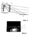
- FIG. 3 an example of such a wavelength-dependent transmission characteristic of the filter is shown in diagram form.
- the transmission rate T is a function over the wavelength A.
- the attenuation for the visible range (380-780nm) is very strong at about 90%.
- the suppression of radiation in the NIR range (780-1100nm) is only about 4%.
- a combination of the location-dependent characteristic with a wavelength-specific transmission characteristic also achieves a strong attenuation of the NIR radiation from the near field and an equally good transmission of VIS and NIR radiation for the remaining image sensor surface area.
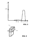
- FIG. 4 an embodiment of an inventively coated with an optical filter image sensor surface 11 is set out for use in a night vision system for motor vehicles sketched.
- the image sensor surface 11 has a coating that attenuates depending on the location only for a portion 24 of the image sensor surface incident there radiation.
- the coating 24 is made of a suitable material, as mentioned above.
- the filter effect can have a location-dependent characteristic, which is achieved, for example, by applying different coatings at different locations.
Landscapes
- Engineering & Computer Science (AREA)
- Physics & Mathematics (AREA)
- Multimedia (AREA)
- General Physics & Mathematics (AREA)
- Radar, Positioning & Navigation (AREA)
- Remote Sensing (AREA)
- Computer Networks & Wireless Communication (AREA)
- Optics & Photonics (AREA)
- Health & Medical Sciences (AREA)
- Electromagnetism (AREA)
- Toxicology (AREA)
- Mechanical Engineering (AREA)
- Signal Processing (AREA)
- Studio Devices (AREA)
- Blocking Light For Cameras (AREA)
- Closed-Circuit Television Systems (AREA)
Description
Die Erfindung geht aus von einem Nachtsichtsystem für Kraftfahrzeuge, das eine Kamera mit einer strahlungsempfindlichen Bildsensorfläche enthält, eingerichtet zum Erfassen von elektromagnetischer Strahlung insbesondere aus dem nahen Infrarotbereich.The invention relates to a night vision system for motor vehicles, which contains a camera with a radiation-sensitive image sensor surface, configured for detecting electromagnetic radiation, in particular from the near infrared range.
Dazu gehören vor allem Nachtsichtsysteme, die die Sicht des Fahrers bei nicht eingeschaltetem konventionellem Fernlicht verbessern.These include, above all, night vision systems which improve the driver's view when the conventional high beam is not switched on.
Systeme zur Nachtsichtunterstützung halten vermehrt Einzug in Kraftfahrzeuge. Nachtsichtsysteme haben zum Ziel, die Sicht des Fahrers über den Abblendlichtbereich hinaus durch Einsatz von Kameras und Displays oder Windschutzscheibenprojektionen bei Nacht zu verbessern. Dabei soll der Gegenverkehr nicht geblendet werden, wie es beim konventionellen Fernlicht, das auch Licht im sichtbaren Bereich aufweist, der Fall wäre.
Nachtsichtunterstützung wird durch den Einsatz und die Erfassung von Wellenlängenbereichen erreicht, die für das menschliche Auge nicht sichtbar sind. Diese werden über Kameras mittels Displays oder Windschutzscheibenprojektionen (z.B. durch Head-up-Displays) dem Fahrer zugänglich gemacht.Systems for night vision support are increasingly finding their way into motor vehicles. Night Vision systems aim to enhance the driver's vision beyond the low beam range by using cameras and displays or night windshield projections. In this case, oncoming traffic should not be dazzled, as would be the case with conventional high beam, which also has light in the visible range.
Night vision support is achieved through the use and detection of wavelength ranges that are invisible to the human eye. These are done via cameras using displays or windshield projections (eg by head-up displays) made accessible to the driver.
Konventionelle Halogcnscheinwerfer (Fern- und Abblendlicht) enthalten sowohl spektrale Anteile im sichtbaren Bereich (VIS, 380nm - 780nm, vgl. DIN5030 Teil2) als auch im nahen Infrarot (NTR IR-A, 780nm - 1400nm). NTR-Fernscheinwerfer aktueller Bauart verwenden konventionelle Halogenglühlampen und blenden mittels optischen Filtern den sichtbaren Bereich aus. Zukünftig werden auch auf Lasern oder LEDs basierende NIR-Fernscheinwerfer verfügbar sein. Videokameras auf Basis von CCD- oder CMOS-Technologie weisen eine spektrale Empfindlichkeit auf, die von etwas 380nm bis ca. 1100nm reicht. Vom NIR-IR-A-Bereich wird also nur der Bereich zwischen 780nm und 1100nm genutzt. Dieser wird im folgenden als NIR-Bereich bezeichnet.Conventional halogen headlights (high and low beam) contain spectral components in the visible range (VIS, 380nm - 780nm, see DIN5030 part 2) as well as in the near infrared (NTR IR-A, 780nm - 1400nm). NTR spotlights of current design use conventional halogen incandescent lamps and hide the visible area by means of optical filters. In future, laser-based or NIR-based headlights will also be available. Video cameras based on CCD or CMOS technology have a spectral sensitivity ranging from about 380nm to about 1100nm. From the NIR-IR-A range, only the range between 780nm and 1100nm is used. This is referred to below as the NIR range.
Aus
Zusätzlich kann zur weiteren Reduzierung von Störlicht auch ein nicht gezeigtes räumliches Absorptionsfilter vor der Kamera angebracht werden, das zum Beispiel die unteren Bereiche des Bildes schwächt und damit den heller ausgeleuchteten Vordergrund schwächt, zuguns-ten des weniger ausgeleuchteten Hintergrunds. Eine weitere Alternative dazu stellt ein spati-aler Lichtmodulator vor der Kamera dar, der dann gezielt nur die zu hellen Partien des Bildes im Kamerasystem schwächt.Additionally, to further reduce stray light, a spatial absorption filter, not shown, may also be placed in front of the camera which, for example, weakens the lower portions of the image and thus weakens the brighter illuminated foreground, in favor of the less illuminated background. Another alternative to this is a spatial light modulator in front of the camera, which then selectively attenuates only the too bright parts of the image in the camera system.
Aus
Aus
Aus
Aus
In verschiedenen bekannten Nachtsichtsystemen wird der nicht sichtbare Nahinfrarotbereich (NIR-Bereich) mit Wellenlängen von 780 bis ca. 1100 nm verwendet. Bei diesen NIR-basierten sogenannten aktiven Systemen (im Gegensatz zu auf Wärmestrahlung des fernen Infrarot basierenden Systemen) wird der von NIR-Fernscheinwerfern des Kraftfahrzeugs ausgeleuchtete Bereiche als Nahinfrarotbild zur Nachtsichtunterstützung des Fahrers mit einer Videokamera erfasst und mittels Display (konventionell oder Head-up-Display) für den Fahrer visualisiert.In various known night vision systems, the invisible near-infrared (NIR) region having wavelengths of 780 to about 1100 nm is used. In these NIR-based so-called active systems (as opposed to far-infrared heat radiation systems), the areas illuminated by NIR vehicle headlamps are captured as a near-infrared image for driver night vision support with a video camera and displayed (conventional or head-up). Display) visualized for the driver.
Bei reinen NIR-Systemen (ohne Nutzung des VIS- Bereichs) wird von der Kamera lediglich das Bild aus dem NIR-Bereich von 780nm - ca. 1100nm aufgenommen und für den Fahrer auf einem Display oder Head-up-Display sichtbar gemacht. In Kunihiko Toyofuku et al.: "The "Night View System" using Near-Infrared Night", in SAE 2003-01-0018, S.33 - S.38, wird ein solches System offenbart. Dort unterdrückt ein Blockfilter im Strahlengang vor dem Bildsensor (Imager) komplett die Aufnahme des sichtbaren Bereichs (VIS-Bereich), also die Wellenlängen von 380 bis 780 nm. Damit werden jedoch bei den für die Nachtsichtunterstützung relevanten Bildbereichen mögliche Verbesserungen der Bildqualität durch Strahlung aus dem sichtbaren (VIS) Bereich verhindert und dem Fahrer sicherheitsrelevante Informationen vorausfahrender Fahrzeuge wie z.B. LED-basierte Bremsleuchten vorenthalten, die nur im sichtbaren Bereich verfügbar sind.For pure NIR systems (without using the VIS area), the camera captures only the image from the NIR area of 780nm - approx. 1100nm and makes it visible to the driver on a display or head-up display. In Kunihiko Toyofuku et al .: "The" Night View System "Using Near-Infrared Night", in SAE 2003-01-0018, p.33 - p.38, such a system is disclosed. There suppresses a block filter in the beam path in front of the image sensor (imager) completely the recording of the visible range (VIS range), ie the wavelengths from 380 to 780 nm. However, with the image areas relevant for the night vision support possible improvements of the image quality are prevented by radiation from the visible (VIS) area and the driver safety-relevant information pre-driving vehicles such as LED-based brake lights withheld, which are available only in the visible range.
Des Weiteren sind gemischte NIR-VIS-Systeme bekannt.
Dabei wird sowohl Strahlung aus dem NIR- als auch aus dem VIS-Bereich erfasst, und das Bild auf einem Display visualisiert. Die dafür verwendete Kamera ist in einem Wellenlängenbereich von ca. λ_unten bis λ_oben sensitiv, wobei λ_unten im sichtbaren Bereich zwischen 380nm und 780nm und λ_oben zwischen 780nm und 1100nm im NIR-Bereich liegt.Furthermore, mixed NIR-VIS systems are known.
Both radiation from the NIR and the VIS range is detected, and the image is visualized on a display. The camera used for this purpose is sensitive in a wavelength range of about λ_unten to λ_oben, where λ_unten in the visible range between 380nm and 780nm and λ_oben between 780nm and 1100nm in the NIR range.
Ein Problem bei reinen NIR-Systemen und insbesondere bei den kombinierten NIR-VIS-Systemen ist die ungleichmäßige Ausleuchtung des mit der Kamera erfassten Bereichs. Für die Verbesserung der Sicht bei Nacht ist hauptsächlich die Visualisierung des Sichtfeldes über den Abblendlichtbereich hinaus interessant. Der Abblendlichtbereich (im folgenden als Nahbereich bezeichnet) ist durch das Abblendlicht bereits hinreichend ausgeleuchtet und daher von untergeordneter Bedeutung, wird aber trotzdem (zumindest teilweise) dargestellt, um dem Fahrer die Orientierung bei der Betrachtung des Nachtsichtbildes zu erleichtern. Helle Ausleuchtung des Kamerabildes für diesen Bereich tritt auf, weil sich das konventionelle Abblendlicht und das NIR-Fernlicht ergänzen. Außerdem werden nahe Bereiche prinzipbedingt stärker ausgeleuchtet und heller abgebildet als entfernt liegendere Zonen.
Ein Teil der begrenzten Helligkeits-Dynamik der Kamera und des Displays wird dadurch aufgrund des hellen Nahbereichs "verschenkt", so dass z.B. dunkle Bereiche jenseits des Nahbereichs (im folgenden als Fernbereich bezeichnet) nicht mehr so gut aufgelöst werden können.
Außerdem wird die Aufmerksamkeit des Fahrers verstärkt auf den hellen Nahbereich gelenkt, so dass die Wahrnehmung von kritischen Details im Fernbereich erschwert wird.A problem with pure NIR systems and especially with the combined NIR-VIS systems is the uneven illumination of the area covered by the camera. For the improvement of the view at night is mainly the visualization of the field of view beyond the low beam range interesting. The low beam range (hereinafter referred to as short range) is already sufficiently illuminated by the low beam and is therefore of lesser importance, but nevertheless (at least partially) presented to facilitate the driver's orientation when viewing the night vision image. Bright illumination of the camera image for this area occurs because the conventional low beam and the NIR high beam complement each other. In addition, near areas are inherently more illuminated and brighter than more distant zones.
Part of the limited brightness dynamics of the camera and the display is due to the bright close range "give away", so that, for example, dark areas beyond the near range (referred to below as distance range) can no longer be resolved as well.
In addition, the driver's attention is increasingly directed to the bright near range, making it difficult to perceive critical details in the far field.
Eine von Software-Algorithmen in der Bildverarbeitung (bei rein darstellenden Systemen auch als Bildbearbeitung bezeichnet) rechnerisch durchgeführte Abdunklung von unerwünscht hellen Bereichen erfordert großen Rechenaufwand und zusätzlichen Speicherplatz, was die Kosten für das entsprechend ausgerüstete Nachtsichtsteuergerät erhöht.
Bei einfachen Nachtsichtsystemen, die keinen Bildverarbeitungsrechner enthalten, ist eine solche softwaregestützte Nachbearbeitung des Kamerabildes nicht möglich.
Auch können durch eine softwaregestützte Nachbearbeitung Übersteuerungen des Imagers aufgrund begrenzter Helligkeits-Dynamik nicht mehr korrigiert werden. Außerdem ist eine wellenlängenabhängige Abschwächung des Nahbereichs über Software-Algorithmen bei Grauwertkameras nicht möglich, bei Farbkameras nur mit großem Aufwand.One of software algorithms in image processing (in purely illustrative systems also referred to as image processing) computationally performed darkening of undesirably bright areas requires large computational effort and additional storage space, which increases the cost of appropriately equipped night vision control unit.
In simple night vision systems that do not contain an image processing computer, such a software-supported post-processing of the camera image is not possible.
Also, a software-assisted post-processing overmodulation of the imager can not be corrected due to limited brightness dynamics. In addition, a wavelength-dependent attenuation of the near range via software algorithms is not possible with gray level cameras, with color cameras only with great effort.
Mit den Maßnahmen des unabhängigen Anspruchs 1 wird erreicht, dass ohne die Zuhilfenahme von bildverarbeitenden Software-Algorithmen eine Abschwächung der erfassten Strahlung auf vorbestimmten Teilbereichen der Bildsensorfläche der Kamera des Nachtsichtssystems erfolgt, auf die regelmäßig sonst unerwünscht hohe Strahlungsintensität entfallen würde. Dadurch, dass die Abschwächung der Strahlung erfindungsgemäß in vorbestimmten Teilbereichen durch ein entsprechend in dem Strahlengang des Nachtsichtsystems angeordnetes optisches Filterelement bewirkt wird, ist die Strahlung bereits vor der Erfassung in der Bildsensorfläche in den gewünschten Bildbereichen, wie insbesondere dem Abbild des zu hellen Nahbereichs, reduziert. Der Strahlengang wird für den Zweck der vorliegenden Erfindung verstanden als der Weg vom beleuchteten Objekt zum Imager, wobei, für die vorliegende Erfindung sich die geeigneten Positionen des Filterelements bevorzugt in dem Abschnitt unmittelbar vor und/oder innerhalb der Kamera befinden.With the measures of the
Kostenintensive Software-Algorithmen zur Bildnachbereitung sind dann für die Abdunklung von Bildbereichen, die rogelmäßig unerwünscht hell wären, entbehrlich. Die Sicht des Fahrers wird auf unkomplizierte Weise mehr auf die für die Nachtsichtunterstützung interessanten Bildausschnitte gelenkt. Eine Übersteuerung von Teilbereichen der Bildsensorfläche wird vermieden und die verfügbare Helligkeitsdynamik von Kamera und Display bezüglich der für die Nachtsichtunterstützung relevanten Bildbereiche besser ausgenutzt.Cost-intensive software algorithms for image post-processing are then dispensable for the darkening of image areas which would be undesirably bright in terms of noise. The view of the driver is more easily directed to the interesting for the night vision support image sections. An override of partial areas of the image sensor surface is avoided and the available brightness dynamics of the camera and the display are better utilized with respect to the image areas relevant for the night vision support.
Das erfindungsgemäße System ist in Anspruch 1 definiert und enthält eine Kamera, die in einem Wellenlängenbereich von 380 bis 1100 nm sensitiv ist. Dabei wird Strahlung sowohl aus dem VIS- als auch aus dem NIR-Bereich erfasst, was die Qualität der Nachtsichtuntorstützung erhöht (z.B. auch LFD-Brems- und Rückleuchten sichtbar) .The system according to the invention is defined in
Das erfindungsgemäße Das erfindungsgemäße Nachtsichtsystem weist die filterbedingte Abschwächung der Strahlung zumindest des Teils der Bildsensorfläche, auf den der Nahbereich aus Fahrersicht abgebildet wird, auf. Es handelt sich dabei um dem Bereich ummittelbar vor dem Kraftfahrzeug, der aus Sicht des Fahrers mittels Abblendlicht bereits ausreichend einsehbar ist. Die hohe Helligkeit, hervorgerufen insbesondere durch Kombination von Abblendlicht und NIR-Fernlicht, wird so in diesem für die Nachtsichtunterstützung uninteressanten Bereich erfindungsgemäß abgeschwächt, was eine Verbesserung der Nachtsicht über den Abblendlichtbereich hinaus zur Folge hat. Die Aufmerksamkeit des Fahrers wird nicht durch große Helligkeit im Nahbereich abgelenkt. Außerdem wird der Dynamikbereich der Kamera besser ausgenutzt, so dass dunkle Bildbereiche (insbesondere im Fernbereich) höher aufgelöst wenden können.The night vision system according to the invention has the filter-related attenuation of the radiation of at least the part of the image sensor surface to which the proximity region is imaged from the driver's point of view. It is the area immediately before the motor vehicle, which is already sufficiently visible from the perspective of the driver by means of dipped beam. The high brightness, especially caused by the combination of dipped beam and NIR high beam, is thus attenuated according to the invention in this area of interest for night vision support, resulting in an improvement of night vision beyond the low beam range. The attention of the driver is not distracted by high brightness at close range. In addition, the dynamic range of the camera is better utilized, so that dark areas of the picture (especially in the far range) can turn higher resolved.
In den Unteransprüchen sind vorteilhafte Ausgestaltungen Weiterbildungen und Verbesserungen des jeweiligen Gegenstandes der Erfindung angegeben.In the dependent claims advantageous refinements developments and improvements of the respective subject of the invention are given.
Eine vorteilhafte Weiterbildung ist eine wellenlängenabhägige Filtercharakteristik des optischen Filters, wobei diese eine individuell auf die spezielle Verwendung des Systems angepasste Durchlassfunktion aufweist. So kann beispielsweise die Wellenlängencharakteristik des Bildsensors in des Kamera und/oder der Scheinwerfer durch eine inverse Wellenlängencharakteristik des optischen Filters berücksichtigt werden, wodurch über einen großen Wellenlängenbereich hinweg eine homogene spektrale Empfindlichkeit des Gesamtsystems erreicht wird.An advantageous development is a wavelength-dependent filter characteristic of the optical filter, wherein this has an individually adapted to the specific use of the system transmission function. Thus, for example, the wavelength characteristic of the image sensor in the camera and / or the headlamp can be taken into account by an inverse wavelength characteristic of the optical filter, whereby a homogeneous spectral sensitivity of the overall system is achieved over a large wavelength range.
Durch die Wahl unterschiedlicher spektraler Bereiche von Abblendlicht und NIR-Fernlicht, kann eine Abschwächung des Abblendlichts stark vereinfacht werden. Wählt man die Spektren von NIR-Fernlicht und konventionellem Abblendlicht so, dass sie nicht überlappen (z.B. durch Blockung des NIR-Anteils mittels optischem Filter im Abblendlicht-Scheinwerfer), dann ist eine vollständige Unterdrückung des Abblendlichtanteils im NV-Bild möglich (spektrale Separierung) .
Besonders vorteilhaft ist eine Blockung aller spektraler Anteile über ca. 600nm, im Abblendlichtspektrum, da dann die Nachtsicht-Kamera so ausgelegt werden kann (Durchlaßbereich von 600mn bis 1100nm), das trotz Abblendlichtunterdrückung noch LED-Rück- oder Bremsleuchten mit einer Wellenlänge von z.B. 625nm erfaßt werden können. Bei der Auslegung der wollenlängenabhängigen Filtercharakteristik kann das spektrale Reflexionsverhalten der Straße (z.B. von Asphalt) mitberücksichtigt werden.By selecting different spectral ranges of dipped beam and NIR high beam, attenuation of the dipped beam can be greatly simplified. If the spectra of NIR main beam and conventional dipped beam are selected so that they do not overlap (eg by blocking the NIR component by means of an optical filter in the dipped beam headlamp), then a complete suppression of the dipped beam component in the NV image is possible (spectral separation) ,
Particularly advantageous is a blockage of all spectral components over about 600nm, in the low beam, since then the night vision camera can be designed (pass band of 600mn to 1100nm), the low beam despite LED backlight or brake lights with a wavelength of eg 625nm despite Abblendlichtunterdrückung can be detected. In the design of the wavelength-dependent filter characteristic, the spectral Reflection behavior of the road (eg asphalt) are taken into account.
Eine zusätzliche Verbesserung stellt die Auswechselbarkeit des optischen Filters dar. Dies ermöglicht eine einfache Anpassung an unterschiedliche Fahrzeugtypen oder - varianten. Auch Nachrüstsysteme können damit einfach an verschiedene Fahrzeugtypen angepaßt werden.An additional improvement is the interchangeability of the optical filter. This allows easy adaptation to different vehicle types or variants. Even retrofit systems can thus be easily adapted to different vehicle types.
Besonders geeignet zur effektiven Abschwächung von Strahlung aus einem bestimmten Objektbereich wie z.B. dem Nahbereich ist die Positionierung des Filters direkt vor der Bildsensorfläche. Ein optischer Filter als Beschichtung auf der Bildsensorfläche ist dabei eine vorteilhafte Variante, denn eine Befestigungseinrichtung für den Filter entfällt dadurch. Alternativ kann das Filter als Beschichtung auf einem Abdeckglas für den Bildsensor (Glas-Lid) angebracht sein, das den eigentlichen Bildsensor und seine Bonddrähte vor Beschädigung schützt. Alternativ kann das Lid selbst als optisches Filter ausgeprägt sein. Günstig kann auch eine Integration des Filters ins Objektiv sein. Hier bietet sich insbesondere die Beschichtung der letzten, dem Imager zugewandten Linse an.Particularly suitable for the effective attenuation of radiation from a certain object area, such as e.g. In the near range, the positioning of the filter is directly in front of the image sensor surface. An optical filter as a coating on the image sensor surface is an advantageous variant, since a fastening device for the filter is thereby eliminated. Alternatively, the filter may be applied as a coating on a cover glass for the image sensor (glass lid), which protects the actual image sensor and its bonding wires from damage. Alternatively, the lid itself may be expressed as an optical filter. It can also be beneficial to integrate the filter into the lens. Here, in particular, the coating of the last, the imager facing lens offers.
Anhand der Zeichnungen werden Ausführungsbeispiele der Erfindung erläutert.With reference to the drawings, embodiments of the invention will be explained.
Es zeigen
- Fig. 1
- ein Blockschaltbild einer Ausführungsform des erfin- dungsgemäßen Nachtsichtsystems für Kraftfahrzeu- ge;
- Fig. 2
- eine Skizze eines Querschnitts einer Kamera mit im Strahlengang eines Nachtsichtsystems erfindungs- gemäß angeordnetem Filterelement zur Abschwächung erfasster Strahlung aus dem Nahbereich;
- Fig. 3
- ein Diagramm zur Darstellung einer wellenlängenab- hängigen Durchlasscharakteristik eines Beispiels für ein erfindungsgemäß im Strahlengang eines Nachtsichtsystems verwendbares Filterelement.
- Fig. 4
- eine Skizze einer Ausführungsform einer Bildsensor- fläche mit einer erfindungsgemäßen als Filter wirksamen Beschichtung, eingerichtet zur Verwen- dung in einem Nachtsichtsystem für Kraftfahrzeu- ge;
- Fig. 5
- eine skizzenhafte Darstellung der örtlichen Intensi- tätsverteilung des Abblendlichts zur Veranschau- lichung einer möglichst inversen, örtlichen Cha- rakteristik einer Ausführungsform eines optischen Filters zur Abschwächung des Nahbereichs, einge- richtet zur Verwendung in einem Nachtsichtsystem für Kraftfahrzeuge.;
- Fig. 1
- a block diagram of an embodiment of the inventive night vision system for motor vehicles ge;
- Fig. 2
- a sketch of a cross-section of a camera with in the beam path of a night-vision system invention according arranged filter element for attenuation detected radiation from the near area;
- Fig. 3
- a diagram showing a wavelength-dependent transmission characteristic of an example of an inventively usable in the beam path of a night vision system filter element.
- Fig. 4
- a sketch of an embodiment of an image sensor surface with a filter according to the invention as a filter effective for use in a night vision system for motor vehicles ge;
- Fig. 5
- a sketch of the local intensity distribution of the dipped beam to show an inverse as possible local characteristic of an embodiment of an optical filter for attenuation of the near range, set up for use in a night vision system for motor vehicles .;
In den Figuren bezeichnen gleiche Bezugszeichen gleiche oder funktionsgleiche Komponenten.In the figures, the same reference numerals designate the same or functionally identical components.
Nach Aktivierung des Nachtsichtsystems durch eine Bedieneinheit 13, schaltet die Kontrolleinheit 3 die NIR-Fernlichtscheinwerfer 5 ein. Diese Scheinwerfer 5 leuchten im NIR-Wellenlängenbereich ( 780 bis ca. 1100nm) einen ähnlichen räumlichen Bereich wie bei konventionellem Fernlicht vor dem Kraftfahrzeug aus. Die Reichweite beträgt ungefähr 250 Meter.After activation of the night vision system by an operating
Eine auch für den NIR-Bereich sensitive Kamera 7 mit CCD- oder CMOS-Bildsensor (jeweils mit linearer oder nichtlinearer Intensitätskennlinie) mit einem Schärftentiefenbereich von ca. 2m bis unendlich erfasst unter anderem die von Objekten, die sich im NIR-Fernlichtbereich befinden, reflektierte NIR-Strahlung. Erfindungsgemäß ist die Kamera 7 mit einem in dem Strahlengang des Nachtsichtsystems 1 angeordneten optischen Filterelement 9 ausgestattet, mit dem die Strahlung auf einem vorbestimmten Teilbereich der Bildsensorfläche 11 in der Kamera 7 abgeschwächt wird. Die Bildsensorfläche ist beispielsweise ein CCD- oder CMOS-ChipA
Die von der Kamera 7 erfassten Bilddaten werden über die Kontrolleinheit 3 an eine Darstellungseinheit 15 übermittelt. In der Darstellungseinheit 15 wird das Bild der Kamera auf einem Display 17 für den Fahrer visualisiert. Das Display 17 ist beispielsweise ein sogenanntes "head-up display", mit dem das visualisierte Bild der Kamera für den Fahrer gut sichtbar auf einen unteren Teil der Windschutzscheibe geworfen wird.The image data captured by the
In
Wie der Fachmann erkennen wird, ist das Filterelement 9 möglichst nahe an der Bildsensorfläche 11 zu haben, um eine möglichst scharfe Grenze zwischen Nahbereichsabbildung und Fernbereichsabbildung mit möglichst geringem Überlapp zu haben, damit möglichst wenige Strahlen von Bildpunkten aus dem Fernbereich gefiltert abgebildet werden, und möglichst viele Strahlen aus dem Nahbereich 20 durch das Filter 9 gefiltert werden.As the person skilled in the art will recognize, the
Dabei wird die aus dem Nahbereich 20 von der Kamera 7 erfasste Strahlung über das Kameraobjektiv 22, das zusammengefasst als eine Linse dargestellt ist, auf einen oberen Bereich der Bildsensorfläche 11, den sogenannten Nahbereichs-Bildbereich 24 projiziert. Direkt vor diesem Nahbereichs-Bildbereich 24 ist erfindungsgemäß das Filterelement 9 angeordnet.
Das Filterelement 9 kann aus dem Material/den Schichten eines handelsüblichen Interferenzfilters oder Absorptionsfilters bestehen. Dieser Filter 9 schwächt die Strahlung aus dem Nahbereich 20 nach seiner Wellenlängencharakteristik ab. Auf den übrigen Teil der Bildsensorfläche 11 trifft die ungefilterte Strahlung, die vom Fernbereich kommt. Beispielsweise ist ein Filter, dessen Abschwächung der Strahlung die inverse ortsabhängige Charakteristik der Abbildung des Abblendlichts des Kraftfahrzeugs aufweist, vor der Bildsensorfläche 11 angebracht. Es sind auch andere Filterelemente, die einen über den reinen Nahbereich hinausreichenden Bereich abdecken, möglich. Diese weisen beispielsweise eine ortsabhängige Filtercharakteristik auf, die sich an der Gesamt-Intensität der von der Kamera 7 erfassten Strahlung orientieren und damit nicht nur eine Überstrahlung des Nahbereichs korrigieren, sondern zusätzlich auch Inhomogenitäten im Fernbereich durch eine inverse Charakteristik kompensieren. So kann eine homogene Intensität des gesamten Sichtbereichs der Kamera erzielt werden, so daß beispielsweise die Vignettierung kompensiert wird. Der Filter 9 bzw. die Filterbechichtung kann dann die gesamte Imagerfläche oder aber nur Teile davon beeinflussen.In this case, the radiation detected by the
The
Der Filter 9 kann auch eine wellenlängenabhängige Durchlasscharakteristik aufweisen. Außerdem ist eine Kombination von ortsabhängiger und wellenlängenabhängiger Charakteristik möglich.The
In
Die Transmissionsrate T ist eine Funktion über der Wellenlänge A. Die Abschwächung für den sichtbaren Bereich (380-780nm) ist mit ca. 90% sehr stark. Hingegen beträgt die Unterdrückung der Strahlung im NIR-Bereich (780-1100nm) nur ca. 4%. Eine Kombination der ortsabhängigen Charakteristik mit einer wellenlängenspezifischen Durchlaßcharakteristik erzielt eine ebenfalls starke Abschwächung der NIR-Strahlung aus dem Nahbereich und einen für den übrigen Bildsensorflächenbereich gleich guten Durchlass von VIS- und NIR-Strahlung.The transmission rate T is a function over the wavelength A. The attenuation for the visible range (380-780nm) is very strong at about 90%. By contrast, the suppression of radiation in the NIR range (780-1100nm) is only about 4%. A combination of the location-dependent characteristic with a wavelength-specific transmission characteristic also achieves a strong attenuation of the NIR radiation from the near field and an equally good transmission of VIS and NIR radiation for the remaining image sensor surface area.
In
Mit Bezug zu der örtlichen Filtercharakteristik gibt
Da der Filter 9 (in
Für dunkle Bereiche soll es bevorzugt keine Abschwächung durch das Filter und für helle Bereiche soll es eine starke Abschwächung durch den Filter 9 geben. Die zwischenliegenden Helligkeitsstufen sollten möglichst kontinuierlich ebenfalls invers abgebildet werden.
Die örtlich unterschiedliche Abschwächung und die möglichst stufenlose Variation des Transmissionsvermögens des Filters 9 ist auf unterschiedliche Weise realisierbar:
- Zum einen durch eine örtlich unterschiedliche Aufbringung einer unterschiedlichen Anzahl von Dämpfungsschichten gleicher Transmissivität:
- Eine Dämpfungsschicht weist beispielsweise eine Transmissivität von 95% auf. Werden dann z.B. 5 Schichten übereinander aufgebracht, dann erhält man eine Gesamtdurchlässigkeit von 95
% hoch 5 = 77%. Die unterschiedliche Anzahl von Schichten an verschiedenen Orten kann beispielsweise über Masken und mehrmaliges Beschichten realisiert werden.
- Eine Dämpfungsschicht weist beispielsweise eine Transmissivität von 95% auf. Werden dann z.B. 5 Schichten übereinander aufgebracht, dann erhält man eine Gesamtdurchlässigkeit von 95
Since the filter 9 (in
For dark areas, there should preferably be no attenuation through the filter and for bright areas there should be a strong attenuation through the
The locally different attenuation and the infinitely variable variation of the transmittance of the
- On the one hand by a spatially different application of a different number of damping layers of the same transmissivity:
- An attenuation layer has, for example, a transmissivity of 95%. If, for example, 5 layers are applied one above the other, then a total permeability of 95% high 5 = 77% is obtained. The different number of Layers at different locations can be realized, for example, via masks and repeated coating.
Zum Anderen durch örtlich unterschiedliche Aufbringung verschiedener Schichten mit unterschiedlicher Transmissivität. So werden nacheinander z.B. Schichten mit Transmissivitäten von 95%, 90%, 85%, ... über mehrere Masken aufgebracht, die nicht überlappen.
Die beiden Verfahren können auch kombiniert werden.On the other hand by spatially different application of different layers with different transmissivity. For example, layers with transmissivities of 95%, 90%, 85%, ... are applied successively over several masks that do not overlap.
The two methods can also be combined.
Claims (6)
- Night vision system (1) for motor vehicles, including a camera (7) with an image sensor (11), set up to detect electromagnetic radiation from the visible (VIS) and infrared (NIR) regions, a filter element (9) being provided which is arranged in the beam path of the night vision system (1) in such a way that it effects an attenuation of the detected radiation which is projected onto predetermined subregions of the image sensor, the camera (7) being sensitive in a wavelength region from 400 to 1100 nm, the filter-induced attenuation of the radiation comprising at least the portion of the image sensor surface (11) onto which the near range (20) from the driver's point of view is projected, the near range from the driver's point of view being the region directly in front of the motor vehicle which can already be sufficiently visible from the point of view of the driver by means of dipped beam, and the attenuation being very strong at approximately 90% for the visible region from 380 nm to 780 nm and the suppression of the radiation in the region from 780 nm to 1100 nm being only approximately 4%, characterized in that the filter element (9) has a spatially dependent filter characteristic and is located directly in front of the subregion of the image sensor onto which the near range is projected such that the radiation from the near range (20) is attenuated in accordance with the wavelength characteristic of the filter element (9), and the unfiltered radiation which comes from the far range strikes the remaining portion of the image sensor surface (11).
- Night vision system (1) according to Claim 1, characterized in that the filter element (9) has a wavelength-dependent filter characteristic, the latter having a transmission function adapted to this specific use of the system (1).
- Night vision system (1) according to either of Claims 1 and 2, characterized in that the filter element (9) can be exchanged.
- Night vision system (1) according to either of Claims 1 and 2, characterized in that the filter element (9) is provided as a coating (24) on the image sensor (11).
- Night vision system according to either of Claims 1 and 2, in which the filter element (9) is designed as an integrated part of a protective glass for the image sensor (11).
- Night vision system (1) according to one of Claims 1 to 5, in which the spectra of NIR main beam and conventional dipped beam overlap as little as possible or not at all.
Applications Claiming Priority (2)
| Application Number | Priority Date | Filing Date | Title |
|---|---|---|---|
| DE102004001556A DE102004001556A1 (en) | 2004-01-10 | 2004-01-10 | Night vision system for motor vehicles with partial optical filter |
| PCT/EP2004/053035 WO2005066684A1 (en) | 2004-01-10 | 2004-11-22 | Night vision system for motor vehicles, comprising a partial optical filter |
Publications (2)
| Publication Number | Publication Date |
|---|---|
| EP1706773A1 EP1706773A1 (en) | 2006-10-04 |
| EP1706773B1 true EP1706773B1 (en) | 2010-08-25 |
Family
ID=34716437
Family Applications (1)
| Application Number | Title | Priority Date | Filing Date |
|---|---|---|---|
| EP04820035A Expired - Fee Related EP1706773B1 (en) | 2004-01-10 | 2004-11-22 | Night vision system for motor vehicles, comprising a partial optical filter |
Country Status (5)
| Country | Link |
|---|---|
| US (1) | US20070278406A1 (en) |
| EP (1) | EP1706773B1 (en) |
| CN (1) | CN100426046C (en) |
| DE (2) | DE102004001556A1 (en) |
| WO (1) | WO2005066684A1 (en) |
Families Citing this family (31)
| Publication number | Priority date | Publication date | Assignee | Title |
|---|---|---|---|---|
| DE10315741A1 (en) * | 2003-04-04 | 2004-11-04 | Daimlerchrysler Ag | Device for improving the visibility in a motor vehicle |
| DE102005049307A1 (en) * | 2005-10-12 | 2007-04-19 | Siemens Ag | Image recording device for the infrared range |
| EP2007132B1 (en) * | 2006-03-28 | 2013-05-08 | Kyocera Corporation | Night vision device |
| US7527440B1 (en) * | 2006-06-05 | 2009-05-05 | White Osborn L | Triangular vehicle light apparatus with camera |
| JP4434234B2 (en) * | 2007-05-30 | 2010-03-17 | トヨタ自動車株式会社 | VEHICLE IMAGING SYSTEM AND VEHICLE CONTROL DEVICE |
| DE102007053307A1 (en) * | 2007-11-08 | 2009-05-14 | Robert Bosch Gmbh | Camera for detecting a vehicle environment |
| DE102008014912B4 (en) | 2008-03-19 | 2023-01-19 | Vorwerk & Co. Interholding Gmbh | Automatically movable floor dust collector |
| DE102008062790A1 (en) * | 2008-12-19 | 2010-06-24 | Visumotion Gmbh | Method and arrangement for spatial representation |
| DE102009000001B4 (en) | 2009-01-02 | 2019-01-24 | Robert Bosch Gmbh | Image sensor and method of manufacturing an image sensor |
| DE102009036595A1 (en) * | 2009-08-07 | 2011-02-10 | Conti Temic Microelectronic Gmbh | Imaging multifunction sensor |
| JP5525277B2 (en) * | 2010-02-10 | 2014-06-18 | 株式会社小糸製作所 | Vehicle lighting with built-in camera |
| US9507462B2 (en) * | 2012-06-13 | 2016-11-29 | Hong Kong Applied Science and Technology Research Institute Company Limited | Multi-dimensional image detection apparatus |
| US9870753B2 (en) | 2013-02-12 | 2018-01-16 | Gentex Corporation | Light sensor having partially opaque optic |
| CN105247861B (en) | 2013-03-22 | 2017-11-10 | 精工爱普生株式会社 | Infrared video shows glasses |
| WO2015013711A1 (en) * | 2013-07-26 | 2015-01-29 | Gentex Corporation | Light sensor having partially opaque optic |
| US9485439B2 (en) * | 2013-12-03 | 2016-11-01 | Sensors Unlimited, Inc. | Shortwave infrared camera with bandwidth restriction |
| US10095086B2 (en) * | 2013-12-23 | 2018-10-09 | Lg Electronics Inc. | Camera module |
| DE102014201181A1 (en) * | 2014-01-23 | 2015-07-23 | Robert Bosch Gmbh | Camera system, in particular for a vehicle, and method for determining image information of a time-pulsed signal source |
| WO2016152682A1 (en) * | 2015-03-23 | 2016-09-29 | 株式会社小糸製作所 | Image pickup device for vehicle, lamp fitting for vehicle, and electronic control unit |
| CN104773079A (en) * | 2015-03-26 | 2015-07-15 | 淮南圣丹网络工程技术有限公司 | Automobile distance light blind spot imaging device |
| DE102015005697B4 (en) * | 2015-05-04 | 2019-10-02 | Mekra Lang Gmbh & Co. Kg | Camera system for a motor vehicle |
| CN106470299B (en) * | 2015-08-18 | 2022-12-23 | 杭州海康机器人股份有限公司 | Lens, camera, package detection system and image processing method |
| EP3396412A4 (en) * | 2015-12-21 | 2019-08-21 | Koito Manufacturing Co., Ltd. | Vehicular sensor, and vehicle provided with same |
| WO2017161520A1 (en) * | 2016-03-23 | 2017-09-28 | 徐鹤菲 | Composite imaging system and mobile terminal supporting near-infrared light and visible-light imaging |
| JP6786302B2 (en) * | 2016-08-12 | 2020-11-18 | 株式会社小糸製作所 | Lighting device |
| CN107765258B (en) * | 2016-08-22 | 2021-02-05 | 原相科技股份有限公司 | Optical detection device for judging relative position of reference object or light source |
| JP2018031888A (en) * | 2016-08-24 | 2018-03-01 | 豊田合成株式会社 | Near-infrared sensor cover |
| JP6759995B2 (en) | 2016-11-11 | 2020-09-23 | 株式会社デンソー | Image processing device |
| DE102017210379A1 (en) * | 2017-06-21 | 2018-12-27 | Robert Bosch Gmbh | Image sensor module |
| JP6912757B2 (en) * | 2017-09-08 | 2021-08-04 | 三菱自動車工業株式会社 | Vehicle headlight controller |
| US10582136B2 (en) * | 2018-03-22 | 2020-03-03 | GM Global Technology Operations LLC | Camera apparatus and operating method thereof |
Family Cites Families (11)
| Publication number | Priority date | Publication date | Assignee | Title |
|---|---|---|---|---|
| US3704375A (en) * | 1970-05-05 | 1972-11-28 | Barnes Eng Co | Monolithic detector construction of photodetectors |
| DE4137551A1 (en) * | 1990-03-10 | 1993-03-11 | Daimler Benz Ag | View improving appts., partic. for vehicle - converts impinging light into output signals in reception optic depending on distance. |
| DE4107850B4 (en) * | 1990-03-10 | 2006-06-29 | Daimlerchrysler Ag | Arrangement for improving visibility, especially in vehicles |
| FR2732849B1 (en) * | 1995-04-07 | 1997-06-20 | Valeo Vision | INFRARED CAMERA DEVICE FOR A VISION AID SYSTEM IN A MOTOR VEHICLE, AND SYSTEM INCORPORATING THE SAME |
| US5781243A (en) * | 1995-05-08 | 1998-07-14 | Hughes Electronics | Display optimization for night vision enhancement systems |
| JPH11194089A (en) * | 1997-08-20 | 1999-07-21 | Daimler Benz Ag | Determining method of road surface condition |
| CN2321026Y (en) * | 1997-10-13 | 1999-05-26 | 广东省普宁市雄鹰实业公司 | Multi-functional safe driving night-vision glasses and holder thereof |
| US6730913B2 (en) * | 2002-02-21 | 2004-05-04 | Ford Global Technologies, Llc | Active night vision system for vehicles employing short-pulse laser illumination and a gated camera for image capture |
| JP2003259363A (en) * | 2002-02-27 | 2003-09-12 | Denso Corp | Night vision apparatus |
| DE10315741A1 (en) * | 2003-04-04 | 2004-11-04 | Daimlerchrysler Ag | Device for improving the visibility in a motor vehicle |
| DE10335189A1 (en) * | 2003-07-30 | 2005-03-03 | Daimlerchrysler Ag | Device for improving the visibility of motor vehicles |
-
2004
- 2004-01-10 DE DE102004001556A patent/DE102004001556A1/en not_active Withdrawn
- 2004-11-22 WO PCT/EP2004/053035 patent/WO2005066684A1/en active Application Filing
- 2004-11-22 DE DE502004011592T patent/DE502004011592D1/en active Active
- 2004-11-22 US US10/583,201 patent/US20070278406A1/en not_active Abandoned
- 2004-11-22 EP EP04820035A patent/EP1706773B1/en not_active Expired - Fee Related
- 2004-11-22 CN CNB2004800402076A patent/CN100426046C/en not_active Expired - Fee Related
Also Published As
| Publication number | Publication date |
|---|---|
| DE502004011592D1 (en) | 2010-10-07 |
| DE102004001556A1 (en) | 2005-08-04 |
| CN1902522A (en) | 2007-01-24 |
| CN100426046C (en) | 2008-10-15 |
| WO2005066684A1 (en) | 2005-07-21 |
| EP1706773A1 (en) | 2006-10-04 |
| US20070278406A1 (en) | 2007-12-06 |
Similar Documents
| Publication | Publication Date | Title |
|---|---|---|
| EP1706773B1 (en) | Night vision system for motor vehicles, comprising a partial optical filter | |
| DE102004050181B4 (en) | Active night vision system with adaptive imaging | |
| EP1580092B1 (en) | Camera in a vehicle | |
| DE102016111783B4 (en) | Display device for superimposing a virtual image in the field of view of a user | |
| EP1214224B1 (en) | Sensor device for a motor vehicle used for detecting environmental parameters | |
| DE102017116849A1 (en) | Indirect vision system for a vehicle | |
| DE10203421C1 (en) | Automobile display unit for IR night visibility device has image processor for reducing brightness level of identified bright points in night visibility image | |
| EP1465002B9 (en) | Camera with infrared filter for improving the visibility in a motor vehicle | |
| EP1503224A2 (en) | Device for improved visiblity in vehicles | |
| DE102016012341A1 (en) | Driver assistance system for a motor vehicle with an exposure-compensated camera | |
| DE102008042012A1 (en) | Image acquisition device for driver assistance system of motor vehicle, has camera and lighting device, where camera has image sensor for image acquisition | |
| DE102008043880A1 (en) | Lighting unit for a vehicle, vehicle and method therefor | |
| WO2001007276A1 (en) | Eye protecting device | |
| DE10016184A1 (en) | Car night vision system eliminates blurred images prevents eye strain | |
| DE102015221970A1 (en) | Projection device for a motor vehicle | |
| DE102015005697B4 (en) | Camera system for a motor vehicle | |
| EP1829373B1 (en) | Device for continuously observing objects independently from ambient light | |
| DE102004039334B4 (en) | Device for improving the visibility in vehicles and vehicles | |
| DE102008002553B4 (en) | Image pickup assembly and night vision system with an image pickup assembly | |
| DE102008031593A1 (en) | Camera system for use in motor vehicle to assist driver during e.g. reversing vehicle, has filter system formed from red, green, blue and weight color filters, and evaluation arrangement with compensating unit to compensate infrared parts | |
| DE10359345B3 (en) | Device for improving the visibility in a motor vehicle | |
| EP1262369A2 (en) | Night vision device for vehicles | |
| DE102012201761A1 (en) | Device and method for directing radiation in the direction of an optical element of an image capture device of a vehicle | |
| DE102013114308B4 (en) | Hardware design of a camera for dynamic rearview mirror | |
| DE102021127180A1 (en) | Method for operating a headlight device for a vehicle and motor vehicle with a headlight device |
Legal Events
| Date | Code | Title | Description |
|---|---|---|---|
| PUAI | Public reference made under article 153(3) epc to a published international application that has entered the european phase |
Free format text: ORIGINAL CODE: 0009012 |
|
| 17P | Request for examination filed |
Effective date: 20060810 |
|
| AK | Designated contracting states |
Kind code of ref document: A1 Designated state(s): DE FR IT SE |
|
| DAX | Request for extension of the european patent (deleted) | ||
| RBV | Designated contracting states (corrected) |
Designated state(s): DE FR IT SE |
|
| 17Q | First examination report despatched |
Effective date: 20090210 |
|
| GRAP | Despatch of communication of intention to grant a patent |
Free format text: ORIGINAL CODE: EPIDOSNIGR1 |
|
| GRAS | Grant fee paid |
Free format text: ORIGINAL CODE: EPIDOSNIGR3 |
|
| GRAA | (expected) grant |
Free format text: ORIGINAL CODE: 0009210 |
|
| AK | Designated contracting states |
Kind code of ref document: B1 Designated state(s): DE FR IT SE |
|
| REF | Corresponds to: |
Ref document number: 502004011592 Country of ref document: DE Date of ref document: 20101007 Kind code of ref document: P |
|
| PGFP | Annual fee paid to national office [announced via postgrant information from national office to epo] |
Ref country code: FR Payment date: 20101130 Year of fee payment: 7 |
|
| PG25 | Lapsed in a contracting state [announced via postgrant information from national office to epo] |
Ref country code: SE Free format text: LAPSE BECAUSE OF FAILURE TO SUBMIT A TRANSLATION OF THE DESCRIPTION OR TO PAY THE FEE WITHIN THE PRESCRIBED TIME-LIMIT Effective date: 20100825 |
|
| PG25 | Lapsed in a contracting state [announced via postgrant information from national office to epo] |
Ref country code: IT Free format text: LAPSE BECAUSE OF FAILURE TO SUBMIT A TRANSLATION OF THE DESCRIPTION OR TO PAY THE FEE WITHIN THE PRESCRIBED TIME-LIMIT Effective date: 20100825 |
|
| PGFP | Annual fee paid to national office [announced via postgrant information from national office to epo] |
Ref country code: DE Payment date: 20110125 Year of fee payment: 7 |
|
| PLBE | No opposition filed within time limit |
Free format text: ORIGINAL CODE: 0009261 |
|
| STAA | Information on the status of an ep patent application or granted ep patent |
Free format text: STATUS: NO OPPOSITION FILED WITHIN TIME LIMIT |
|
| 26N | No opposition filed |
Effective date: 20110526 |
|
| REG | Reference to a national code |
Ref country code: DE Ref legal event code: R097 Ref document number: 502004011592 Country of ref document: DE Effective date: 20110526 |
|
| REG | Reference to a national code |
Ref country code: FR Ref legal event code: ST Effective date: 20120731 |
|
| REG | Reference to a national code |
Ref country code: DE Ref legal event code: R119 Ref document number: 502004011592 Country of ref document: DE Effective date: 20120601 |
|
| PG25 | Lapsed in a contracting state [announced via postgrant information from national office to epo] |
Ref country code: FR Free format text: LAPSE BECAUSE OF NON-PAYMENT OF DUE FEES Effective date: 20111130 |
|
| PG25 | Lapsed in a contracting state [announced via postgrant information from national office to epo] |
Ref country code: DE Free format text: LAPSE BECAUSE OF NON-PAYMENT OF DUE FEES Effective date: 20120601 |