EP1705785B1 - Vibrator tube - Google Patents
Vibrator tube Download PDFInfo
- Publication number
- EP1705785B1 EP1705785B1 EP05006110A EP05006110A EP1705785B1 EP 1705785 B1 EP1705785 B1 EP 1705785B1 EP 05006110 A EP05006110 A EP 05006110A EP 05006110 A EP05006110 A EP 05006110A EP 1705785 B1 EP1705785 B1 EP 1705785B1
- Authority
- EP
- European Patent Office
- Prior art keywords
- magnet assembly
- permanent magnet
- dimension
- electromagnetic vibrator
- vibrator according
- Prior art date
- Legal status (The legal status is an assumption and is not a legal conclusion. Google has not performed a legal analysis and makes no representation as to the accuracy of the status listed.)
- Not-in-force
Links
- 239000011554 ferrofluid Substances 0.000 claims abstract description 28
- 239000000203 mixture Substances 0.000 claims abstract description 8
- 239000012530 fluid Substances 0.000 claims description 9
- 239000002105 nanoparticle Substances 0.000 claims description 7
- 239000002245 particle Substances 0.000 claims description 5
- 230000001846 repelling effect Effects 0.000 claims description 5
- 229910000859 α-Fe Inorganic materials 0.000 claims description 2
- 239000007789 gas Substances 0.000 description 11
- 230000009286 beneficial effect Effects 0.000 description 5
- 230000001419 dependent effect Effects 0.000 description 5
- 239000006249 magnetic particle Substances 0.000 description 3
- 230000006835 compression Effects 0.000 description 1
- 238000007906 compression Methods 0.000 description 1
- 238000006073 displacement reaction Methods 0.000 description 1
- 239000000428 dust Substances 0.000 description 1
- 230000000694 effects Effects 0.000 description 1
- 230000005684 electric field Effects 0.000 description 1
- 230000002349 favourable effect Effects 0.000 description 1
- 239000000314 lubricant Substances 0.000 description 1
- 239000002184 metal Substances 0.000 description 1
- 230000000149 penetrating effect Effects 0.000 description 1
- 230000003068 static effect Effects 0.000 description 1
- 239000011800 void material Substances 0.000 description 1
- 238000004804 winding Methods 0.000 description 1
Images

Classifications
-
- H—ELECTRICITY
- H02—GENERATION; CONVERSION OR DISTRIBUTION OF ELECTRIC POWER
- H02K—DYNAMO-ELECTRIC MACHINES
- H02K33/00—Motors with reciprocating, oscillating or vibrating magnet, armature or coil system
- H02K33/16—Motors with reciprocating, oscillating or vibrating magnet, armature or coil system with polarised armatures moving in alternate directions by reversal or energisation of a single coil system
Definitions
- An object of the present invention is to provide a device for providing quick and efficient vibrations of a portable communication device.
- Another aspect of the present invention is directed towards an electromagnetic vibrator including the features of the eighth aspect, wherein the first and second centering elements comprise a second and a third permanent magnet, respectively, oriented in opposite direction in relation to one another in the first dimension, for exerting centering forces directed in the first dimension on the permanent magnet assembly.
- Another aspect of the present invention is to provide a portable communication device comprising an electromagnetic vibrator comprising:
- the two magnetic fields that is the magnetic field as created by the electric current flowing through the coiling and the one as formed by the magnet, Interact with each other and create relative attracting or repelling forces, dependent on the relativ positon of the magnet and the colling within the housing, and the current that Is fed through the coiling.
- the ferrofluld comprises magnetized or magnetizable nano particles that are dispersed In a carrier fluid.
- Such ferrofluids hence show magnetic properties despite of the fact that the ferrofluid Is a fluid.
- a centering element 46 is schematically shown in the compartment 44 on the right side of the magnet 42.
- the centering element is a spring, of which one end is attached to the magnet and of which the other end is attached to the Interior side of the right hand side end stop 48.
- the spring being one example of a centering element, has the function of centering the magnet within the housing to a position essentially in the center of the housing in the axial dimension.
- the spring 46 there is no requirement for the spring 46 to support the magnet 42 or magnet assembly in a transverse or radial dimension of the housing/vibrator.
- the reason for this Is that there is mechanical sliding contact in the interface 39 between the surface of the magnet assembly and the surface side of the housing 30.
- the magnet assembly is guided by the track which in fig. 3 is shown as an interior cavity.
- the electromagnetic device according to the present invention Is given a high efficiency with only very minor losses when being used.
Landscapes
- Engineering & Computer Science (AREA)
- Power Engineering (AREA)
- Apparatuses For Generation Of Mechanical Vibrations (AREA)
- Reciprocating, Oscillating Or Vibrating Motors (AREA)
- Gripping On Spindles (AREA)
- Mechanical Pencils And Projecting And Retracting Systems Therefor, And Multi-System Writing Instruments (AREA)
Abstract
Description
- The present invention relates to providing tactile stimuli to a user of a portable communication device.
- Vibrators within small communication devices are most commonly designed as direct current (DC) motors where a counter weight is mounted off-center on the rotating axis. Upon rotation of the axis, the counter weight causes the vibrator to vibrate as a function of the rotational frequency.
- There is also another type of vibrators, linear motor type vibtrators, which comprise a magnet and a coll system that are driven by an alternating current (AC) electric source. Linear motor type vibrators typically have a metal spring attached to a top or a bottom of a housing in order to provide support to the magnet system. One example of such a linear vibrator is described in IP2004-174309.
- Until today the best performance has been achieved by the DC-motor type vibrators. However, there are disadvantages with this type of vibrators. The first disadvantage is that the response time is too long to enable a quick vibration response required in, for example, gaming. A second disadvantage is that the counter weight is not protected against dust and mechanical damage to the same degree as the interior of the motor itself.
- A drawback of the linear motor type vibrator is that the efficiency in terms of vibration is only about 25-50% of that of a DC-motor type vibrator.
- The
american patent document U56768230 - The
patent document US 2003/114999 A1 discloses an electromagnetic vibrator for use in a portable communication device comprising a housing with a track directed in a first dimension, a coil and a permanent magnet assembly arranged for motion along the track. - There is hence still a need to overcome the deficiences of the vibrators as presented above, to achieve an efficient vibrator, having a short response time without comprising any mechanical parts that can be damaged from outside influences.
- The Invention is directed towards solving the problem of overcoming slow and unefficient provision of tactile stimull to a user of a portable communication device.
- This is achieved by providing quick and efficient vibrations of a portable communication device.
- An object of the present invention is to provide a device for providing quick and efficient vibrations of a portable communication device.
- According to this invention, this object is achieved by an electromagnetic vibrator for use In a portable communication device comprising:
- a housing comprising a track directed in a first dimension,
- a coiling comprising at least one coil turn, oriented in a second dimension essentially perpendicular to the first dimension, coiled around the track and being arranged to receive an electric voltage,
- a permanent magnet assembly arranged for motion along the track to which said permanent magnet assembly is tightly fitted, and
- a ferrofluid mixture placed between the track and the permanent magnet assembly,
- Wherein the vibrator comprises at least a first centering element located on a first side of the permanent magnet assembly along the first dimension, for exerting an alternating attracting and repelling force directed in the first dimension on the permanent magnet assembly.
- A second aspect of the present invention Is directed towards an electromagnetic vibrator including the features of the first aspect, wherein the ferrofluid is a low friction ferrofluid mixture comprising magnetic or magnetizable nano particles, and a carrier fluid, in which the magnetic or magnetizable nano particles are dispersed.
- Another aspect of the present invention is directed towards an electromagnetic vibrator Including the features of the second aspect, wherein the nano particles comprise ferrite particles and the carrier fluid comprises an organic carrier fluid.
- Another aspect of the present invention is directed towards an electromagnetic vibrator including the features of the first aspect, wherein the track comprises a tubular cavity directed in the first dimension and In which tubular cavity the first permanent magnet assembly is arranged to move.
- Another aspect of the present invention is directed towards an electromagnetic vibrator including the features of the fourth aspect, wherein the tubular cavity has a circular cross section.
- Another aspect of the present invention is directed towards an electromagnetic vibrator including the features of the fourth aspect, wherein the tubular cavity is linear in shape.
- Another aspect of the present Invention is directed towards an electromagnetic vibrator including the features of the seventh aspect, wherein the vibrator comprises a second centering element located on a second side of the permanent magnet assembly along the first dimension, for exerting a centering force directed in the first dimension on the permanent magnet assembly.
- Another aspect of the present invention is directed towards an electromagnetic vibrator including the features of the seventh aspect, wherein the first centering element comprises a first spring of which a first end is attached to a first end of the permanent magnet assembly, and of which a second end is attached to an inner side of a first end stop of the tubular cavity.
- Another aspect of the present invention Is directed towards an electromagnetic vibrator including the features of the eighth aspect, wherein the first and second centering elements comprise a first and a second spring, respectively, attached on either side of the permanent magnet assembly, for exerting centering forces directed In the first dimension on the permanent magnet assembly.
- Another aspect of the present invention is directed towards an electromagnetic vibrator including the features of the ninth aspect, wherein the first and second springs are non-linear in the first dimension.
- Another aspect of the present invention is directed towards an electromagnetic vibrator including the features of the eighth aspect, wherein the first and second centering elements comprise a second and a third permanent magnet, respectively, oriented in opposite direction in relation to one another in the first dimension, for exerting centering forces directed in the first dimension on the permanent magnet assembly.
- Another aspect of the present invention is directed towards an electromagnetic vibrator Including the features of the eighth aspect, wherein the first and second centering elements each comprise an essentially gas tight compartment and wherein there is an essentially gas tight fit at the contact surface between the permanent magnet assembly and the surface wall of the tubular cavity.
- Another aspect of the present invention is directed towards an electromagnetic vibrator including the features of the first aspect, wherein the coiling is arranged to receive an alternating current electric voltage.
- Another aspect of the present Invention is directed towards an electromagnetic vibrator including the features of the first aspect, wherein the tubular cavity has a toroidal shape.
- Another aspect of the present Invention is directed towards an electromagnetic vibrator including the features of the fifteenth aspect, wherein the coiling Is arranged to receive a direct current electric voltage.
- A second object of the present invention is to provide a portable communication device providing quick and efficient vibrations to its user.
- Another aspect of the present invention is to provide a portable communication device comprising an electromagnetic vibrator comprising:
- a housing comprising a track directed in a first dimension,
- a coiling comprising at least one coil turn, oriented in a second dimension essentially perpendicular to the first dimension, around the track and being arranged to receive an electric voltage,
- a permanent magnet assembly arranged for motion along the track, and
- a ferrofluid mixture placed between the track and the permanent magnet assembly,
- The present invention has thus the following overall advantages:
- Firstly, the electromagnetic vibrator is more efficient due to the application of a ferrofluid mixture subjected to a magnetic field.
- Secondly, the electromagnetic vibrator also achieves a shorter response time as the friction between the magnet assembly and the housing or track, Is minimized.
- Thirdly, the electromagnetic vibrator is also void of any mechanical parts that can be damaged from outside influences.
- It should be emphasized that the term "comprises/comprising" when used in this specification is taken to specify the presence of stated features, integers, steps or components, but does not preclude the presence or addition of one or more other features, integers, steps, components or groups thereof.
- The present invention will now be described in more detail in relation to the enclosed drawings, in which:
-
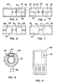
fig. 1 schematically shows a housing-coil system, -
fig. 2 schematically shows housing-coil-magnet system according to one embodiment of the present Invention, -
fig. 3 schematically shows a more detailed housing-magnet arrangement according to one embodiment of the present invention, -
fig. 4 schematically shows a housing-magnet arrangement according to one embodiment of the present invention, -
fig. 5 schematically shows a housing-magnet arrangement according to one embodiment of the present Invention, -
fig. 6 schematically shows a housing-magnet arrangement according to one embodiment of the present invention, -
fig. 7 schematically shows a housing-magnet arrangement according to one embodiment of the present invention, -
fig. 8 schematically shows a housing-coil-magnet arrangement according to one embodiment of the present invention, and -
fig. 9 schematically shows a portable communication device according to one embodiment of the present invention. - The invention is directed towards solving the problem of overcoming slow and unefficient provision of tactile stimuli to a user of a portable communication device.
- Electromagnetic vibrators utilizes the influence on a magnet by a magnetic field, which field generally is created by letting an electric current flow through a colling. Dependent on the design of such magnet-coil system either a direct current (DC) electric voltage or an alternating current (AC) electric voltage is supplied to the coil, enabling an AC electric current and a DC electric current to flow through the coil.
-
Fig. 1 schematically shows an elongatedhollow housing 10 around which a coiling is wound. An electric voltage is applied to theconnections 14, creating amagnetic field 16 that is directed along the long axis of the housing, The direction of the magnetic field is dependent on the polarity of the applied electric voltage. - As is shown in
fig. 2 a housing Is designed to have a circular cross section, forming a hollow straight cylinder. A coiling 22 is would around the circular housing, which coiling is supplied with an electric voltage over theconnectors 24. Amagnet 26 is positioned within thehousing 20. On supplying an electric voltage over the coiling 22 at theconnectors 24, a magnetic field is created within and around the coiling 22. Themagnet 26 Is preferably oriented so that the magnetic axis of the magnet is parallel with the symmetry axis of the cylindrical housing, and most preferably that the directions of the magnetic axis and the center of the magnetic field, created by the coiling, coincide. - The two magnetic fields, that is the magnetic field as created by the electric current flowing through the coiling and the one as formed by the magnet, Interact with each other and create relative attracting or repelling forces, dependent on the relativ positon of the magnet and the colling within the housing, and the current that Is fed through the coiling.
- According to one embodiment of the present invention, the housing has a linear shape, as shown in
fig. 2 , which means that the magnet can be made to move back and fourth within the linear housing, by applying the electrical voltage over theconnectors 24 of the coiling. - According to one embodiment of the present Invention the track is a tubular cavity. The cross section of the tubular cavity may also be circular. According to another embodiment of the present Invention, it may also have any other shape such as rectangular or triangular shape or a non-polynomial shape such a horse-shoe shape or any other shape.
- According to one embodiment the track is a rall that is protruding from a surface within the housing. According to this embodiment the magnet or magnet assembly, as we shall see below, is fitted around or on the track such that the magnet or magnet assembly is guided by the track along the housing upon influence of the magnetic field generated around the coiling.
- Alternatively, the track may also be a trace that is recessing from the surface within the housing, according to another embodiment of the present invention. Here, the magnet or magnet assembly may comprise a rall that Is arranged to fit into the trace recessing from the housing surface. The housing surface may not necessarily be an Interior surface located within the housing, but may very well be an exterior surface of housing having a cross section that is non-closed. One example of such a shape is the horse-shoe shaped housing, as mentioned above.
- With reference to
fig. 3 , schematically showing a more detailed housing-magnet arrangement according to one embodiment of the present invention, the present invention is further explained. - The electromagnetic vibrator according to the present Invention comprises the inclusion of a ferrofluid located in an Interface between the magnet or magnet assembly and a track along which the magnet can be made to move.
- In
fig. 3 , the electromagnetic vibrator, as schematically disclosed, comprises alinear housing 30, apermanent magnet 32 and amagnet support magnet 32 and themagnet support - According to this embodiment of the present Invention, the magnet assembly and the
linear housing 30 are connected over a slidingsurface interface 39. It is this interface that comprises a ferrofluid according to a preferred embodiment of the present invention. - According to one embodiment of the present invention, the ferrofluld comprises magnetized or magnetizable nano particles that are dispersed In a carrier fluid. Such ferrofluids hence show magnetic properties despite of the fact that the ferrofluid Is a fluid.
- Upon positioning a ferrofluid within a magnetic field the fluid, experiences a force and travels in the direction of the magnetic field lines. Such a movement along the magnetic field lines results in a collection of ferrofluid at positions where the density of magnetic field lines is high, that is where the magnetic field strength is high. As magnetic particles experience a force along the field lines, the particles are not moved across the magnetic field lines. If a surface for this reason is crossed by magnetic field lines, a ferrofluld containing particles that are magnetic, experiences an attraction force from this surface, or rather the magnetic field crossing the surface.
- In principle, a repulsion force could be experienced, but since the repulsion force alternative is energetically non-favourable over the attraction alternative, the magnetic particles experience an attraction force.
- Due to this attraction force the magnetic ferrofluid is collected on the surface. Since the ferrofluid travels along the magnetic field lines, an orientation of the magnetic field lines and the surface for which the magnetic field lines are paralell with the normal to the surface, that Is perpendicular to the plane of the surface, is beneficial for maintaining the ferrofluid on the surface.
- In case the normal of the surface would be perpendicular to the magnetic field lines, the ferrofluid would not remain on the surface, but rather be attracted away in the direction of the field lines. This would hence result In a surface without comprising any ferrofluid.
- In practise, orientations for which the angle between the normal to the surface and the magnetic field lines, is less than about n/4 rad (that Is 45 degrees), lend the magnetic particles of the ferrofluid the attraction force, which makes the ferrofluid remain on the surface.
- Returning to
fig. 3 , a fewmagnetic field lines 38 are schematically Indicated. At the slidingsurface interface 39 between the magnet assembly and thehousing 30, the magnetic field line is approximately parallel with the normal to the surface of theinterface 39. This will thus be beneficial since the ferrofluid will remain on the surface and not travel away from the surface. - According to one embodiment of the present invention, when applying a ferrofluid comprising magnetized particles on the interface surface between the housing and the magnet assembly, the friction between said housing surface and the magnet assembly is very low, due to the properties of the ferrofluid when subjected to magnetic field lines crossing the surface interface.
- A very low friction in the interface between the magnet assembly and the housing means that the magnet assembly can move back and/or fourth along the housing with very little losses upon application of an electric field over the
connectors figs. 1 and 2 , respectively. - According to one embodiment of the present invention, a very efficient electromagnetic vibrator is thus achieved.
- For a linear vibrator the magnet assembly including the magnet is intended to move back and forth within the housing and inside the coiling. In order to move the magnet In one direction one polarity of the electric voltage, that is applied to the coiling, is required, and in order to move the magnet in the opposite direction the reverse polarity of the electric voltage is needed. If an alternating current electric voltage Is applied to the coiling the magnet assembly would thus move back and forth in one dimension as determined by the track or the housing, that is back In one direction and forth in the opposite direction. As such an electric voltage is applied the magnet assembly can be made to move back and forth without the assistance by any further elements or effects.
- When an electromagnetic vibrator according to the present invention, is not in use, the magnet assembly would still experience a very low friction against the housing surface, which could make the magnet assembly to hit the top end or bottom end of the housing or tubular cavity, since the magnetic field from the magnet remains unchanged. Such a behaviour is disadvantageous since it would create mechanical damage to the electromagnetic vibrator, at the same time as it could create an unpleasant tactile experience for a user of a portable communication device comprising the electromagnetic vibrator. In addition, hitting a top end and/or bottom end would cause an un-desired nolse.
- As the motion direction of the magnet assembly Is dependent on the polarity of the applied electrical voltage, an applied polariy causing the magnet assembly to move away from the center of the coiling, is un-wanted In case the magnet assembly already is postioned near or at either one of the top end or bottom end of the housing. If such an electric voltage is applied to the coiling when the magnet assembly is positioned near or at the end of the housing, the magnet assembly could again hit the bottom end or top end of the housing, creating the problems as described in the paragraphs above.
- In order to avoid hitting the top or bottom end of the housing by the magnet assembly, one or two centering elements are introduced In the housing, for centering the magnet assembly in the axial direction of the housing.
- By referring to
figs. 4-7 , schematically showing housing-magnet arrangements, different embodiments of the present invention are explained, by focusing on the centering elements comprised in the respective housing. -
Fig. 4 discloses one embodiment In which the electromagnetic vibrator comprises ahousing 40, amagnet 42, a right handside end stop 48 and acompartment 44 that is formed between themagnet 42 and the right handside end stop 48. On the left side of themagnet 42 in the Interior of the housing a second compartment is also formed between the magnet and a left hand side end stop, (not denoted infig. 4 ). - In the
compartment 44 on the right side of themagnet 42, a centeringelement 46 is schematically shown. According to this embodiment of the present invention, the centering element is a spring, of which one end is attached to the magnet and of which the other end is attached to the Interior side of the right handside end stop 48. The spring, being one example of a centering element, has the function of centering the magnet within the housing to a position essentially in the center of the housing in the axial dimension. - The
spring 46 has the advantage that it allows the back- and forth motion of the magnet or magnet assembly, since the spring according to this embodiment allows both an elongation upon pulling of the magnet, and a compression upon pushing of the magnet. - According to one embodiment of the present invention there is no requirement for the
spring 46 to support themagnet 42 or magnet assembly in a transverse or radial dimension of the housing/vibrator. The reason for this Is that there is mechanical sliding contact in theinterface 39 between the surface of the magnet assembly and the surface side of thehousing 30. The magnet assembly is guided by the track which infig. 3 is shown as an interior cavity. - A non-linear spring can be characterized by having a force function, rather than a force constant, as the ratio of an applied longitudinal force and the change in length of the spring. The usage of a non-linear spring allows a greater amplitude of the moving magnet in the axial dimension for a constant loss, maintaining the centering element functionality.
- According to one embodiment of the present Invention, the centering element is a non-linear spring.
-
Fig. 5 schematically shows another embodiment of the present invention, an electromagnetic vibrator comprising two centeringelements element 56 is positioned in afirst compartment 54 and a second centeringelement 57 Is positioned in asecond compartment 55. - According to one embodiment, the left side of the
first spring 56 is attached to the right side of themagnet 52 or magnet assembly, and the right side of thespring 56 is attached to the left side of the right side end stop 58 of thehousing 50 or the entire electromagnetic vibrator. Similarly the left side of thesecond spring 57 is attached to the right side of leftside end stop 59, and the right side of thespring 57 is attached to the left side of themagnet 52 or magnet assembly. - Analoguous to another embodiment that was described above, there is no requirement of the first and
second springs - In addition, the first and
second springs springs - In
fig. 6 an electromagnetic vibrator according to another embodiment of the present invention is presented. Within this embodiment the centering elements each comprise a centeringmagnet 66,68 that is oriented to exert a repelling force on the moving magnet 62. On the right side the right compartment 64 is defined as the volume within the right side of the moving magnet 62 or magnet assembly, the housing 60, and the left side of the left centering magnet 66. Theleft compartment 65 is similarly defined as the volume comprised within the left side of the moving magnet 62, the housing 60 and the right side of the centeringmagnet 68. The right and left centering magnets are thus examples of right and left end stops of the housing 60. - Due to the repelling forces between the moving magnet 62 and the
centerings magnets 66, 68, the moving magnet is hindered from hitting either one of the left or right end stops, which in this embodiment are comprised by the centerings elements of the electromagnetic vibrator. - The moving magnet 62 or magnet assembly within the above described embodiments in
figs. 4, 5 and 6 , may be designed with axial channels penetrating through the moving magnet and or the support structure, comprised In the magnet assembly, to allow a gas, for example air, to flow between the two compartments, minimizing the Influence of the enclosed gas in the compartments on the motion of the magnet. -
Fig. 7 , shows yet another embodiment of the electromagnetic vibrator according to the present invention, comprising ahousing 70 and a right end stop 76 and aleft end stop 78 of the housing. According to this embodiment the housing and the right and left end stops are tightly fitted together forming a gas tight enclosure. In addition themagnet 72 or magnet assembly is also tightly fitted against thehousing 70. The tight seal between the magnet assembly and the housing is realized by ferrofluld being applied in the interface between the magnet assembly and the housing (seefig. 3 wherein the interface is denoted with 39). Within this embodiment of the present invention, the left and right compartments are thus essentially gas tight. - Since gases are compressible, the gas tight compartments filled with a gas receive a spring function, exerting a pushing force on the moving magnet assembly when being compressed, and a pulling force when being decompressed. By changing the gas pressure of the two compartments the forces exerted on the magnet assembly can easily be adjusted.
- The centering elements in this embodiment are thus essentially gas tight compressible and decompresslble compartments, having the beneficial property of comprising a limited number of parts.
- According to an alternative embodiment of the present invention the tubular cavity onto which the moving magnet is tightly fitted comprises a
toroid 80, as schematically shown infig. 8 . By winding acolling 82 around thetoroid 80 and applying a DC- electrical voltage over theconnectors 86 of the coiling 82, amagnet 84 within the tubular cavity, here the torold, 80, experiences auni-directed force 88 moving the magnet in one circular dimension around the toroid. - In this embodiment, as in the other embodiments as presented above, it is beneficial to position the moving magnet within a
supporing structure fig. 3 , in order to orient the magnetic field lines with a substantial component directed parallel with the normal of the sliding surface in the interface between the magnet assembly and the housing. - As the ferrofluid preferably Is applied in the sliding surface interface between the magnet assembly and the housing for all the embodiments, the electromagnetic device according to the present invention Is given a high efficiency with only very minor losses when being used.
- In addition, as the ferrofluid provides a very low friction within the orientation as described above, starting an electromagnetic vibrator by applying an electric voltage over connectors connected to the colling, is performed within a short time, that is the response time from an applied electric voltage until experinced vibrations is very short.
- Due to the design of the electromagnetic vibrators according to the various embodiments as described above, the interior of the vibrator is efficiently protected by the surrounding housing, such that damage on the moving parts due to outside influences is minimized.
-
Fig. 9 presents a portable communication device, comprising an electromagnetic vibrator according to one embodiment of the present invention. In this figure the portable communication device is designed as amobile phone 90 comprising theelectromagnetic vibrator 92. This is only one example of a portable communication device, which may comprise any type of portable computer such as a personal digital assistant, etc. - It is emphasized that this invention can be varied in many ways, of which the alternative embodiments above only are examples of a few. These different embodiments are hence nonlimiting examples. The scope of the present invention, however, is only limited by the subsequently following claims.
- The described present invention thus carries the following advantages:
- The present invention comprises the advantage that the electromagnetic vibrator is more efficient due to the application of a ferrofluld mixture subjected to a magnetic field. In addition, the electromagntic vibrator also achieves a shorter response time as the friction between the magnet assembly and the housing or track, is minimized. The electromagnetic vibrator does moreover not comprise any mechanical parts that can be damaged from outside influences. The low number of mechanical parts, dependent of the embodiment, renders the electromagnetic vibrator being manufacturable at a low cost.
- The present invention brings the advantage that the power consumption for the electromagnetic vibrator is very low.
- The low friction is in addition beneficial for the lifetime of the electromagnetic vibrator.
Claims (16)
- Electromagnetic vibrator for use in a portable communication device (90) comprising:- a housing (20,30,40,50,60,70,80) comprising a track directed in a first dimension,- a coiling (22,82) comprising at least one coil turn, oriented in a second dimension essentially perpendicular to the first dimension, coiled around the track and being arranged to receive an electric voltage, , characterized by:allowing motion of the permanent magnet assembly (26,32,34,42,52,62,72,84) in the first dimension in dependence of the electric voltage as supplied to the coiling (22,82) wherein:- a permanent magnet assembly (26,32,34,42,52,62,72,84) arranged for motion along the track to which said permanent magnet assembly is tightly fitted, and- a ferrofluid mixture placed between the track and the permanent magnet assembly (26,32,34,42,52,62,72,84),the vibrator comprises at least a first centering element (46,56,66,74) located on a first side of the permanent magnet assembly (26,32,34,42,52,62,72,84) along the first dimension, for exerting an alternating attracting and repelling force directed in the first dimension on the permanent magnet assembly (26,32,34,42,52,62,72,84).
- The electromagnetic vibrator according to claim 1, wherein the ferrofluid is a low friction ferrofluid mixture comprising:- magnetic or magnetizable nano particles, and- a carrier fluid, in which the magnetic or magnetizable nano particles are dispersed.
- The electromagnetic vibrator according to claim 2, wherein the nano particles comprise ferrite particles and the carrier fluid comprises an organic carrier fluid.
- The electromagnetic vibrator according to any one of claims 1-3, wherein the track comprises a tubular cavity directed in the first dimension and in which tubular cavity the first permanent magnet assembly (26,32,34,42,52,62,72,84) is arranged to move.
- The electromagnetic vibrator according to claim 4, wherein the tubular cavity has a circular cross section.
- The electromagnetic vibrator according to claims 4 or 5, wherein the tubular cavity is linear in shape.
- The electromagnetic vibrator according to claim 1, wherein the vibrator comprises a second centering element (57,68,75) located on a second side of the permanent magnet assembly (26,32,34,42,52,62,72,84) along the first dimension, for exerting a centering force directed in the first dimension on the permanent magnet assembly (26,32,34,42,52,62,72,84).
- The electromagnetic vibrator according to claim 1, wherein the first centering element comprises a first spring (46,56) of which a first end is attached to a first end of the permanent magnet assembly (42), and of which a second end is attached to an inner side of a first end stop (48) of the tubular cavity.
- The electromagnetic vibrator according to claim 7, wherein the first and second centering elements (56,57) comprise a first and a second spring, respectively, attached on either side of the permanent magnet assembly (26,32,34,42,52,62,72,84), for exerting centering forces directed in the first dimension on the permanent magnet assembly (52).
- The electromagnetic vibrator according to claim 8 or 9, wherein the first and second springs are non-linear in the first dimension.
- The electromagnetic vibrator according to claim 7, wherein the first and second centering elements comprise a second and a third permanent magnet (66,68), respectively, oriented in opposite direction in relation to one another in the first dimension, for exerting centering forces directed in the first dimension on the permanent magnet assembly (62).
- The electromagnetic vibrator according to claim 7, wherein the first and second centering elements (74,75) each comprise an essentially gas tight compartment and wherein there is an essentially gas tight fit at the contact surface between the permanent magnet assembly (72) and the surface wall of the tubular cavity (70).
- The electromagnetic vibrator according to any one of claims 1-12, wherein the coiling (22,82) is arranged to receive an alternating current electric voltage.
- The electromagnetic vibrator according to any one of claims 1-5, wherein the tubular cavity has a toroidal shape (80).
- The electromagnetic vibrator according to claim 14, wherein the coiling (22,82) is arranged to receive a direct current electric voltage.
- A portable communication device (90) comprising an electromagnetic vibrator according to any of the claims 1-15, wherein the portable communication device (90) is a mobile phone.
Priority Applications (6)
| Application Number | Priority Date | Filing Date | Title |
|---|---|---|---|
| DE602005007705T DE602005007705D1 (en) | 2005-03-21 | 2005-03-21 | vibration tube |
| EP05006110A EP1705785B1 (en) | 2005-03-21 | 2005-03-21 | Vibrator tube |
| AT05006110T ATE399388T1 (en) | 2005-03-21 | 2005-03-21 | VIBRATION TUBE |
| US11/909,199 US8018105B2 (en) | 2005-03-21 | 2006-03-15 | Vibrator tube |
| PCT/EP2006/002364 WO2006099979A1 (en) | 2005-03-21 | 2006-03-15 | Vibrator tube |
| CNA2006800092401A CN101189784A (en) | 2005-03-21 | 2006-03-15 | Vibrator tube |
Applications Claiming Priority (1)
| Application Number | Priority Date | Filing Date | Title |
|---|---|---|---|
| EP05006110A EP1705785B1 (en) | 2005-03-21 | 2005-03-21 | Vibrator tube |
Publications (2)
| Publication Number | Publication Date |
|---|---|
| EP1705785A1 EP1705785A1 (en) | 2006-09-27 |
| EP1705785B1 true EP1705785B1 (en) | 2008-06-25 |
Family
ID=34979205
Family Applications (1)
| Application Number | Title | Priority Date | Filing Date |
|---|---|---|---|
| EP05006110A Not-in-force EP1705785B1 (en) | 2005-03-21 | 2005-03-21 | Vibrator tube |
Country Status (6)
| Country | Link |
|---|---|
| US (1) | US8018105B2 (en) |
| EP (1) | EP1705785B1 (en) |
| CN (1) | CN101189784A (en) |
| AT (1) | ATE399388T1 (en) |
| DE (1) | DE602005007705D1 (en) |
| WO (1) | WO2006099979A1 (en) |
Families Citing this family (39)
| Publication number | Priority date | Publication date | Assignee | Title |
|---|---|---|---|---|
| US7934153B2 (en) * | 2005-05-06 | 2011-04-26 | Madcap Software, Inc. | Visual document structure indicator system |
| US7498682B2 (en) * | 2007-03-07 | 2009-03-03 | Aaron Patrick Lemieux | Electrical energy generator |
| JP2009081966A (en) * | 2007-09-27 | 2009-04-16 | Sanyo Electric Co Ltd | Electronic equipment |
| JP2009112069A (en) * | 2007-10-26 | 2009-05-21 | Sanyo Electric Co Ltd | Electronic equipment |
| US8688224B2 (en) * | 2008-03-07 | 2014-04-01 | Tremont Electric, Inc. | Implantable biomedical device including an electrical energy generator |
| WO2010135383A2 (en) * | 2009-05-18 | 2010-11-25 | Resonant Systems, Inc. | Linear-resonant vibration module |
| ES2377656B1 (en) * | 2009-06-16 | 2013-02-06 | Consejo Superior De Investigaciones Científicas (Csic) | DEVICE FOR GENERATING ELECTRICAL ENERGY FROM SMALL MOVEMENTS. |
| US8487759B2 (en) | 2009-09-30 | 2013-07-16 | Apple Inc. | Self adapting haptic device |
| US8704387B2 (en) * | 2010-01-06 | 2014-04-22 | Tremont Electric, Inc. | Electrical energy generator |
| WO2011085093A2 (en) | 2010-01-06 | 2011-07-14 | Tremont Electric, Llc | Electrical energy generator |
| CN101867334B (en) * | 2010-06-12 | 2012-07-04 | 杭州玄能科技有限公司 | Magnetic engine |
| US8963666B2 (en) | 2010-07-21 | 2015-02-24 | Apple Inc. | Programmable magnetic connectors |
| EP2941819B1 (en) * | 2012-12-26 | 2018-03-21 | Nulman, Yanir | Method and apparatus for recovery of parasitic energy losses |
| CN105101918A (en) | 2013-01-22 | 2015-11-25 | 布赖恩·约瑟夫·诺顿 | Transverse-mode-resonant stimulation device |
| JP5766748B2 (en) * | 2013-06-05 | 2015-08-19 | Thk株式会社 | Linear actuator |
| US10236760B2 (en) | 2013-09-30 | 2019-03-19 | Apple Inc. | Magnetic actuators for haptic response |
| US9317118B2 (en) | 2013-10-22 | 2016-04-19 | Apple Inc. | Touch surface for simulating materials |
| GB201404861D0 (en) * | 2014-03-18 | 2014-04-30 | Bish Bash Productions Ltd | Percussion instrument |
| AU2014391723B2 (en) | 2014-04-21 | 2018-04-05 | Apple Inc. | Apportionment of forces for multi-touch input devices of electronic devices |
| KR102143310B1 (en) | 2014-09-02 | 2020-08-28 | 애플 인크. | Haptic notifications |
| EP3198618B1 (en) * | 2014-09-24 | 2021-05-19 | Taction Technology Inc. | Systems and methods for generating damped electromagnetically actuated planar motion for audio-frequency vibrations |
| US10353467B2 (en) | 2015-03-06 | 2019-07-16 | Apple Inc. | Calibration of haptic devices |
| AU2016100399B4 (en) | 2015-04-17 | 2017-02-02 | Apple Inc. | Contracting and elongating materials for providing input and output for an electronic device |
| CN107925333B (en) | 2015-09-08 | 2020-10-23 | 苹果公司 | Linear actuator for use in an electronic device |
| US9850957B2 (en) | 2015-09-30 | 2017-12-26 | Apple Inc. | Electronic device with haptic actuation stiction release after non-movement threshold time period and related methods |
| US10039080B2 (en) | 2016-03-04 | 2018-07-31 | Apple Inc. | Situationally-aware alerts |
| US10268272B2 (en) | 2016-03-31 | 2019-04-23 | Apple Inc. | Dampening mechanical modes of a haptic actuator using a delay |
| US10074469B2 (en) | 2016-06-06 | 2018-09-11 | Apple Inc. | Magnetic materials polarized at an oblique angle |
| US9716423B1 (en) * | 2016-06-24 | 2017-07-25 | Nanoport Technology Inc. | Tactile feedback actuator, electronic device using same, and method of operating same |
| US11133736B2 (en) * | 2016-12-20 | 2021-09-28 | Mitsumi Electric Co., Ltd. | Vibration actuator, wearable terminal, and device with incoming notification function |
| US10622538B2 (en) | 2017-07-18 | 2020-04-14 | Apple Inc. | Techniques for providing a haptic output and sensing a haptic input using a piezoelectric body |
| EP3718191B1 (en) * | 2017-11-30 | 2021-12-15 | Otto S.r.l. | A solenoid generator, corresponding electrical supply system and device |
| US10691211B2 (en) | 2018-09-28 | 2020-06-23 | Apple Inc. | Button providing force sensing and/or haptic output |
| US10599223B1 (en) | 2018-09-28 | 2020-03-24 | Apple Inc. | Button providing force sensing and/or haptic output |
| US11380470B2 (en) | 2019-09-24 | 2022-07-05 | Apple Inc. | Methods to control force in reluctance actuators based on flux related parameters |
| US11977683B2 (en) | 2021-03-12 | 2024-05-07 | Apple Inc. | Modular systems configured to provide localized haptic feedback using inertial actuators |
| US11581828B2 (en) * | 2021-05-05 | 2023-02-14 | Enervibe Ltd | Electromagnetic vibration and energy harvester having vibrating body, magnets and stationary magnet and hinge |
| US11809631B2 (en) | 2021-09-21 | 2023-11-07 | Apple Inc. | Reluctance haptic engine for an electronic device |
| US11716003B1 (en) * | 2022-03-08 | 2023-08-01 | The United States Of America, As Represented By The Secretary Of The Navy | Electromagnetic arrays |
Family Cites Families (10)
| Publication number | Priority date | Publication date | Assignee | Title |
|---|---|---|---|---|
| US3984708A (en) * | 1975-09-11 | 1976-10-05 | The Institutes Of Medical Sciences | Electromagnetic tactile stimulator |
| AU8877398A (en) * | 1997-10-04 | 1999-04-27 | Wei-Min Zhang | Linear motor compressor |
| US5973422A (en) * | 1998-07-24 | 1999-10-26 | The Guitammer Company | Low frequency vibrator |
| US6636007B2 (en) * | 2001-03-12 | 2003-10-21 | Sunonwealth Electric Machine Industry Co., Ltd. | DC brushless vibration motor |
| JP2003154315A (en) | 2001-11-22 | 2003-05-27 | Matsushita Electric Ind Co Ltd | Vibratory linear actuator |
| US7288860B2 (en) * | 2002-02-19 | 2007-10-30 | Teledyne Licensing, Inc. | Magnetic transducer with ferrofluid end bearings |
| US6768230B2 (en) * | 2002-02-19 | 2004-07-27 | Rockwell Scientific Licensing, Llc | Multiple magnet transducer |
| JP2004174309A (en) * | 2002-11-25 | 2004-06-24 | Alps Electric Co Ltd | Vibration device |
| CA2521688C (en) * | 2003-06-26 | 2012-01-03 | Med-El Elektromedizinische Geraete Gmbh | System and method for reducing effect of magnetic fields on a magnetic transducer |
| US7449803B2 (en) * | 2005-03-21 | 2008-11-11 | Sahyoun Joseph Y | Electromagnetic motor to create a desired low frequency vibration or to cancel an undesired low frequency vibration |
-
2005
- 2005-03-21 DE DE602005007705T patent/DE602005007705D1/en active Active
- 2005-03-21 EP EP05006110A patent/EP1705785B1/en not_active Not-in-force
- 2005-03-21 AT AT05006110T patent/ATE399388T1/en not_active IP Right Cessation
-
2006
- 2006-03-15 WO PCT/EP2006/002364 patent/WO2006099979A1/en not_active Application Discontinuation
- 2006-03-15 US US11/909,199 patent/US8018105B2/en not_active Expired - Fee Related
- 2006-03-15 CN CNA2006800092401A patent/CN101189784A/en active Pending
Also Published As
| Publication number | Publication date |
|---|---|
| US8018105B2 (en) | 2011-09-13 |
| EP1705785A1 (en) | 2006-09-27 |
| DE602005007705D1 (en) | 2008-08-07 |
| WO2006099979A1 (en) | 2006-09-28 |
| ATE399388T1 (en) | 2008-07-15 |
| US20080174187A1 (en) | 2008-07-24 |
| WO2006099979A8 (en) | 2008-01-31 |
| CN101189784A (en) | 2008-05-28 |
Similar Documents
| Publication | Publication Date | Title |
|---|---|---|
| EP1705785B1 (en) | Vibrator tube | |
| US9041230B2 (en) | Method and apparatus for motional/vibrational energy harvesting via electromagnetic induction using a magnet array | |
| JP4315811B2 (en) | Dynamic magnet system | |
| US7586220B2 (en) | Electromechanical generator for converting mechanical vibrational energy into electrical energy | |
| JP3863429B2 (en) | Linear vibration actuator | |
| US20140084710A1 (en) | Vibration actuator | |
| KR20060003092A (en) | Reciprocating linear drive actuator and electric toothbrush | |
| KR102049343B1 (en) | Horizontal linear vibrating motor | |
| US9755491B2 (en) | Actuator and electrical appliance having fixed member with a coil and movable members having magnets | |
| US11522430B2 (en) | Linear vibration actuator | |
| US20110068641A1 (en) | Horizontal linear vibrator | |
| JP3165856B2 (en) | Vibration generator | |
| JPS60207440A (en) | Vibration motor | |
| JP2596857Y2 (en) | Moving magnet type actuator | |
| WO2010103929A1 (en) | Vibration motor and portable apparatus | |
| US10715022B2 (en) | Actuator and electric beauty device | |
| JP2011200752A (en) | Vibration motor | |
| JP5795435B2 (en) | Linear motor for hand-held small electric devices | |
| US11658554B2 (en) | Vibrating with stop magnets, mandrel and guiding member | |
| JP2013118332A (en) | Solenoid drive device | |
| JP3523331B2 (en) | Exciter | |
| JP2011166893A (en) | Oscillating generator | |
| JP7371926B2 (en) | linear vibration motor | |
| JP2011078197A (en) | Electromagnetic induction type generator | |
| US11843297B2 (en) | Rotating vibration actuator with a weight and electronic apparatus |
Legal Events
| Date | Code | Title | Description |
|---|---|---|---|
| PUAI | Public reference made under article 153(3) epc to a published international application that has entered the european phase |
Free format text: ORIGINAL CODE: 0009012 |
|
| AK | Designated contracting states |
Kind code of ref document: A1 Designated state(s): AT BE BG CH CY CZ DE DK EE ES FI FR GB GR HU IE IS IT LI LT LU MC NL PL PT RO SE SI SK TR |
|
| AX | Request for extension of the european patent |
Extension state: AL BA HR LV MK YU |
|
| 17P | Request for examination filed |
Effective date: 20070216 |
|
| AKX | Designation fees paid |
Designated state(s): AT BE BG CH CY CZ DE DK EE ES FI FR GB GR HU IE IS IT LI LT LU MC NL PL PT RO SE SI SK TR |
|
| 17Q | First examination report despatched |
Effective date: 20070608 |
|
| GRAP | Despatch of communication of intention to grant a patent |
Free format text: ORIGINAL CODE: EPIDOSNIGR1 |
|
| GRAS | Grant fee paid |
Free format text: ORIGINAL CODE: EPIDOSNIGR3 |
|
| GRAA | (expected) grant |
Free format text: ORIGINAL CODE: 0009210 |
|
| AK | Designated contracting states |
Kind code of ref document: B1 Designated state(s): AT BE BG CH CY CZ DE DK EE ES FI FR GB GR HU IE IS IT LI LT LU MC NL PL PT RO SE SI SK TR |
|
| REG | Reference to a national code |
Ref country code: GB Ref legal event code: FG4D |
|
| REG | Reference to a national code |
Ref country code: CH Ref legal event code: EP |
|
| REF | Corresponds to: |
Ref document number: 602005007705 Country of ref document: DE Date of ref document: 20080807 Kind code of ref document: P |
|
| REG | Reference to a national code |
Ref country code: IE Ref legal event code: FG4D |
|
| PG25 | Lapsed in a contracting state [announced via postgrant information from national office to epo] |
Ref country code: FI Free format text: LAPSE BECAUSE OF FAILURE TO SUBMIT A TRANSLATION OF THE DESCRIPTION OR TO PAY THE FEE WITHIN THE PRESCRIBED TIME-LIMIT Effective date: 20080625 Ref country code: SI Free format text: LAPSE BECAUSE OF FAILURE TO SUBMIT A TRANSLATION OF THE DESCRIPTION OR TO PAY THE FEE WITHIN THE PRESCRIBED TIME-LIMIT Effective date: 20080625 |
|
| PG25 | Lapsed in a contracting state [announced via postgrant information from national office to epo] |
Ref country code: NL Free format text: LAPSE BECAUSE OF FAILURE TO SUBMIT A TRANSLATION OF THE DESCRIPTION OR TO PAY THE FEE WITHIN THE PRESCRIBED TIME-LIMIT Effective date: 20080625 Ref country code: AT Free format text: LAPSE BECAUSE OF FAILURE TO SUBMIT A TRANSLATION OF THE DESCRIPTION OR TO PAY THE FEE WITHIN THE PRESCRIBED TIME-LIMIT Effective date: 20080625 Ref country code: PL Free format text: LAPSE BECAUSE OF FAILURE TO SUBMIT A TRANSLATION OF THE DESCRIPTION OR TO PAY THE FEE WITHIN THE PRESCRIBED TIME-LIMIT Effective date: 20080625 |
|
| NLV1 | Nl: lapsed or annulled due to failure to fulfill the requirements of art. 29p and 29m of the patents act | ||
| PG25 | Lapsed in a contracting state [announced via postgrant information from national office to epo] |
Ref country code: LT Free format text: LAPSE BECAUSE OF FAILURE TO SUBMIT A TRANSLATION OF THE DESCRIPTION OR TO PAY THE FEE WITHIN THE PRESCRIBED TIME-LIMIT Effective date: 20080625 Ref country code: IS Free format text: LAPSE BECAUSE OF FAILURE TO SUBMIT A TRANSLATION OF THE DESCRIPTION OR TO PAY THE FEE WITHIN THE PRESCRIBED TIME-LIMIT Effective date: 20081025 Ref country code: PT Free format text: LAPSE BECAUSE OF FAILURE TO SUBMIT A TRANSLATION OF THE DESCRIPTION OR TO PAY THE FEE WITHIN THE PRESCRIBED TIME-LIMIT Effective date: 20081125 Ref country code: SE Free format text: LAPSE BECAUSE OF FAILURE TO SUBMIT A TRANSLATION OF THE DESCRIPTION OR TO PAY THE FEE WITHIN THE PRESCRIBED TIME-LIMIT Effective date: 20080925 Ref country code: CZ Free format text: LAPSE BECAUSE OF FAILURE TO SUBMIT A TRANSLATION OF THE DESCRIPTION OR TO PAY THE FEE WITHIN THE PRESCRIBED TIME-LIMIT Effective date: 20080625 Ref country code: ES Free format text: LAPSE BECAUSE OF FAILURE TO SUBMIT A TRANSLATION OF THE DESCRIPTION OR TO PAY THE FEE WITHIN THE PRESCRIBED TIME-LIMIT Effective date: 20081006 |
|
| PG25 | Lapsed in a contracting state [announced via postgrant information from national office to epo] |
Ref country code: SK Free format text: LAPSE BECAUSE OF FAILURE TO SUBMIT A TRANSLATION OF THE DESCRIPTION OR TO PAY THE FEE WITHIN THE PRESCRIBED TIME-LIMIT Effective date: 20080625 Ref country code: BE Free format text: LAPSE BECAUSE OF FAILURE TO SUBMIT A TRANSLATION OF THE DESCRIPTION OR TO PAY THE FEE WITHIN THE PRESCRIBED TIME-LIMIT Effective date: 20080625 Ref country code: RO Free format text: LAPSE BECAUSE OF FAILURE TO SUBMIT A TRANSLATION OF THE DESCRIPTION OR TO PAY THE FEE WITHIN THE PRESCRIBED TIME-LIMIT Effective date: 20080625 |
|
| PG25 | Lapsed in a contracting state [announced via postgrant information from national office to epo] |
Ref country code: BG Free format text: LAPSE BECAUSE OF FAILURE TO SUBMIT A TRANSLATION OF THE DESCRIPTION OR TO PAY THE FEE WITHIN THE PRESCRIBED TIME-LIMIT Effective date: 20080925 Ref country code: EE Free format text: LAPSE BECAUSE OF FAILURE TO SUBMIT A TRANSLATION OF THE DESCRIPTION OR TO PAY THE FEE WITHIN THE PRESCRIBED TIME-LIMIT Effective date: 20080625 Ref country code: DK Free format text: LAPSE BECAUSE OF FAILURE TO SUBMIT A TRANSLATION OF THE DESCRIPTION OR TO PAY THE FEE WITHIN THE PRESCRIBED TIME-LIMIT Effective date: 20080625 |
|
| PLBE | No opposition filed within time limit |
Free format text: ORIGINAL CODE: 0009261 |
|
| STAA | Information on the status of an ep patent application or granted ep patent |
Free format text: STATUS: NO OPPOSITION FILED WITHIN TIME LIMIT |
|
| 26N | No opposition filed |
Effective date: 20090326 |
|
| PG25 | Lapsed in a contracting state [announced via postgrant information from national office to epo] |
Ref country code: IT Free format text: LAPSE BECAUSE OF FAILURE TO SUBMIT A TRANSLATION OF THE DESCRIPTION OR TO PAY THE FEE WITHIN THE PRESCRIBED TIME-LIMIT Effective date: 20080625 |
|
| PG25 | Lapsed in a contracting state [announced via postgrant information from national office to epo] |
Ref country code: MC Free format text: LAPSE BECAUSE OF NON-PAYMENT OF DUE FEES Effective date: 20090331 |
|
| REG | Reference to a national code |
Ref country code: CH Ref legal event code: PL |
|
| REG | Reference to a national code |
Ref country code: IE Ref legal event code: MM4A |
|
| PG25 | Lapsed in a contracting state [announced via postgrant information from national office to epo] |
Ref country code: LI Free format text: LAPSE BECAUSE OF NON-PAYMENT OF DUE FEES Effective date: 20090331 Ref country code: IE Free format text: LAPSE BECAUSE OF NON-PAYMENT OF DUE FEES Effective date: 20090321 Ref country code: CH Free format text: LAPSE BECAUSE OF NON-PAYMENT OF DUE FEES Effective date: 20090331 |
|
| PG25 | Lapsed in a contracting state [announced via postgrant information from national office to epo] |
Ref country code: GR Free format text: LAPSE BECAUSE OF FAILURE TO SUBMIT A TRANSLATION OF THE DESCRIPTION OR TO PAY THE FEE WITHIN THE PRESCRIBED TIME-LIMIT Effective date: 20080926 |
|
| PG25 | Lapsed in a contracting state [announced via postgrant information from national office to epo] |
Ref country code: LU Free format text: LAPSE BECAUSE OF NON-PAYMENT OF DUE FEES Effective date: 20090321 |
|
| PG25 | Lapsed in a contracting state [announced via postgrant information from national office to epo] |
Ref country code: HU Free format text: LAPSE BECAUSE OF FAILURE TO SUBMIT A TRANSLATION OF THE DESCRIPTION OR TO PAY THE FEE WITHIN THE PRESCRIBED TIME-LIMIT Effective date: 20081226 |
|
| PG25 | Lapsed in a contracting state [announced via postgrant information from national office to epo] |
Ref country code: TR Free format text: LAPSE BECAUSE OF FAILURE TO SUBMIT A TRANSLATION OF THE DESCRIPTION OR TO PAY THE FEE WITHIN THE PRESCRIBED TIME-LIMIT Effective date: 20080625 |
|
| PG25 | Lapsed in a contracting state [announced via postgrant information from national office to epo] |
Ref country code: CY Free format text: LAPSE BECAUSE OF FAILURE TO SUBMIT A TRANSLATION OF THE DESCRIPTION OR TO PAY THE FEE WITHIN THE PRESCRIBED TIME-LIMIT Effective date: 20080625 |
|
| REG | Reference to a national code |
Ref country code: FR Ref legal event code: PLFP Year of fee payment: 11 |
|
| REG | Reference to a national code |
Ref country code: DE Ref legal event code: R082 Ref document number: 602005007705 Country of ref document: DE Representative=s name: KRAUS & WEISERT PATENTANWAELTE PARTGMBB, DE Ref country code: DE Ref legal event code: R081 Ref document number: 602005007705 Country of ref document: DE Owner name: SONY MOBILE COMMUNICATIONS AB, SE Free format text: FORMER OWNER: SONY ERICSSON MOBILE COMMUNICATIONS AB, LUND, SE Ref country code: DE Ref legal event code: R081 Ref document number: 602005007705 Country of ref document: DE Owner name: SNAPTRACK, INC., SAN DIEGO, US Free format text: FORMER OWNER: SONY ERICSSON MOBILE COMMUNICATIONS AB, LUND, SE |
|
| REG | Reference to a national code |
Ref country code: FR Ref legal event code: CD Owner name: SONY MOBILE COMMUNICATIONS AB Effective date: 20151026 |
|
| REG | Reference to a national code |
Ref country code: FR Ref legal event code: PLFP Year of fee payment: 12 |
|
| REG | Reference to a national code |
Ref country code: DE Ref legal event code: R082 Ref document number: 602005007705 Country of ref document: DE Representative=s name: KRAUS & WEISERT PATENTANWAELTE PARTGMBB, DE Ref country code: DE Ref legal event code: R081 Ref document number: 602005007705 Country of ref document: DE Owner name: SNAPTRACK, INC., SAN DIEGO, US Free format text: FORMER OWNER: SONY MOBILE COMMUNICATIONS AB, LUND, SE |
|
| REG | Reference to a national code |
Ref country code: FR Ref legal event code: TP Owner name: SNAPTRACK, INC., US Effective date: 20160927 |
|
| REG | Reference to a national code |
Ref country code: GB Ref legal event code: 732E Free format text: REGISTERED BETWEEN 20161110 AND 20161116 |
|
| REG | Reference to a national code |
Ref country code: GB Ref legal event code: 732E Free format text: REGISTERED BETWEEN 20161117 AND 20161123 |
|
| REG | Reference to a national code |
Ref country code: FR Ref legal event code: PLFP Year of fee payment: 13 |
|
| REG | Reference to a national code |
Ref country code: FR Ref legal event code: PLFP Year of fee payment: 14 |
|
| PGFP | Annual fee paid to national office [announced via postgrant information from national office to epo] |
Ref country code: DE Payment date: 20180308 Year of fee payment: 14 Ref country code: GB Payment date: 20180223 Year of fee payment: 14 |
|
| PGFP | Annual fee paid to national office [announced via postgrant information from national office to epo] |
Ref country code: FR Payment date: 20180223 Year of fee payment: 14 |
|
| REG | Reference to a national code |
Ref country code: DE Ref legal event code: R119 Ref document number: 602005007705 Country of ref document: DE |
|
| GBPC | Gb: european patent ceased through non-payment of renewal fee |
Effective date: 20190321 |
|
| PG25 | Lapsed in a contracting state [announced via postgrant information from national office to epo] |
Ref country code: GB Free format text: LAPSE BECAUSE OF NON-PAYMENT OF DUE FEES Effective date: 20190321 Ref country code: DE Free format text: LAPSE BECAUSE OF NON-PAYMENT OF DUE FEES Effective date: 20191001 |
|
| PG25 | Lapsed in a contracting state [announced via postgrant information from national office to epo] |
Ref country code: FR Free format text: LAPSE BECAUSE OF NON-PAYMENT OF DUE FEES Effective date: 20190331 |