EP1701074B1 - Soft ventable relief valve - Google Patents
Soft ventable relief valve Download PDFInfo
- Publication number
- EP1701074B1 EP1701074B1 EP20060251297 EP06251297A EP1701074B1 EP 1701074 B1 EP1701074 B1 EP 1701074B1 EP 20060251297 EP20060251297 EP 20060251297 EP 06251297 A EP06251297 A EP 06251297A EP 1701074 B1 EP1701074 B1 EP 1701074B1
- Authority
- EP
- European Patent Office
- Prior art keywords
- pilot
- pressure
- valve
- main
- chamber
- Prior art date
- Legal status (The legal status is an assumption and is not a legal conclusion. Google has not performed a legal analysis and makes no representation as to the accuracy of the status listed.)
- Active
Links
- 239000012530 fluid Substances 0.000 claims description 53
- 238000013016 damping Methods 0.000 claims description 12
- 238000004891 communication Methods 0.000 claims description 6
- 238000007789 sealing Methods 0.000 claims 1
- 230000006835 compression Effects 0.000 description 5
- 238000007906 compression Methods 0.000 description 5
- 230000036316 preload Effects 0.000 description 4
- 230000035939 shock Effects 0.000 description 4
- 230000000903 blocking effect Effects 0.000 description 2
- 230000001276 controlling effect Effects 0.000 description 2
- 238000013461 design Methods 0.000 description 2
- 238000007599 discharging Methods 0.000 description 2
- XDDAORKBJWWYJS-UHFFFAOYSA-N glyphosate Chemical compound OC(=O)CNCP(O)(O)=O XDDAORKBJWWYJS-UHFFFAOYSA-N 0.000 description 2
- 230000013011 mating Effects 0.000 description 2
- 238000013022 venting Methods 0.000 description 2
- 239000000654 additive Substances 0.000 description 1
- 230000000996 additive effect Effects 0.000 description 1
- 238000013459 approach Methods 0.000 description 1
- 238000010276 construction Methods 0.000 description 1
- 230000001627 detrimental effect Effects 0.000 description 1
- 238000006073 displacement reaction Methods 0.000 description 1
- 238000004519 manufacturing process Methods 0.000 description 1
- 230000001105 regulatory effect Effects 0.000 description 1
- 230000000630 rising effect Effects 0.000 description 1
- 238000004513 sizing Methods 0.000 description 1
- 238000012360 testing method Methods 0.000 description 1
- 238000011144 upstream manufacturing Methods 0.000 description 1
Images

Classifications
-
- F—MECHANICAL ENGINEERING; LIGHTING; HEATING; WEAPONS; BLASTING
- F16—ENGINEERING ELEMENTS AND UNITS; GENERAL MEASURES FOR PRODUCING AND MAINTAINING EFFECTIVE FUNCTIONING OF MACHINES OR INSTALLATIONS; THERMAL INSULATION IN GENERAL
- F16K—VALVES; TAPS; COCKS; ACTUATING-FLOATS; DEVICES FOR VENTING OR AERATING
- F16K17/00—Safety valves; Equalising valves, e.g. pressure relief valves
- F16K17/02—Safety valves; Equalising valves, e.g. pressure relief valves opening on surplus pressure on one side; closing on insufficient pressure on one side
- F16K17/04—Safety valves; Equalising valves, e.g. pressure relief valves opening on surplus pressure on one side; closing on insufficient pressure on one side spring-loaded
- F16K17/0433—Safety valves; Equalising valves, e.g. pressure relief valves opening on surplus pressure on one side; closing on insufficient pressure on one side spring-loaded with vibration preventing means
-
- Y—GENERAL TAGGING OF NEW TECHNOLOGICAL DEVELOPMENTS; GENERAL TAGGING OF CROSS-SECTIONAL TECHNOLOGIES SPANNING OVER SEVERAL SECTIONS OF THE IPC; TECHNICAL SUBJECTS COVERED BY FORMER USPC CROSS-REFERENCE ART COLLECTIONS [XRACs] AND DIGESTS
- Y10—TECHNICAL SUBJECTS COVERED BY FORMER USPC
- Y10T—TECHNICAL SUBJECTS COVERED BY FORMER US CLASSIFICATION
- Y10T137/00—Fluid handling
- Y10T137/7722—Line condition change responsive valves
- Y10T137/7758—Pilot or servo controlled
- Y10T137/7762—Fluid pressure type
- Y10T137/7764—Choked or throttled pressure type
- Y10T137/7766—Choked passage through main valve head
-
- Y—GENERAL TAGGING OF NEW TECHNOLOGICAL DEVELOPMENTS; GENERAL TAGGING OF CROSS-SECTIONAL TECHNOLOGIES SPANNING OVER SEVERAL SECTIONS OF THE IPC; TECHNICAL SUBJECTS COVERED BY FORMER USPC CROSS-REFERENCE ART COLLECTIONS [XRACs] AND DIGESTS
- Y10—TECHNICAL SUBJECTS COVERED BY FORMER USPC
- Y10T—TECHNICAL SUBJECTS COVERED BY FORMER US CLASSIFICATION
- Y10T137/00—Fluid handling
- Y10T137/7722—Line condition change responsive valves
- Y10T137/7758—Pilot or servo controlled
- Y10T137/7762—Fluid pressure type
- Y10T137/7769—Single acting fluid servo
- Y10T137/777—Spring biased
Landscapes
- Engineering & Computer Science (AREA)
- General Engineering & Computer Science (AREA)
- Mechanical Engineering (AREA)
- Safety Valves (AREA)
Description
- This invention relates generally to pressure control valves in hydraulic systems, and more particularly to a soft ventable relief valve which eliminates pressure spikes and hydraulic shock in such systems.
- Pressure relief valves are used to provide a quick opening for excessive hydraulic pressure in a hydraulic system into which the valve is installed. These valves are characterized by a structure by which hydraulic pressure in the system is regulated by relieving and venting some of the pressurized fluid back to a supply tank or reservoir.
- All conventional relief valves such as a differential piston relief valve or a pilot operated relief valve have a significant shortcoming when installed into a hydraulic system. When the hydraulic system is actuated so as to energize a hydraulic actuator, cylinder or motor, pressure increases virtually instantaneously. As a result, there is a sharp hydraulic spike in the pressure level of the fluid system which results in excessively abrupt energizing of the hydraulic motor. Not only is this operational limitation abusive to the system, but it may also be operationally detrimental in that the equipment being operated will exhibit too sharp a start-up.
- Other patented relief valves claiming a "soft start" feature are disclosed in
U.S. Patent 4,653,527 to Kosarzecki, inU.S. Patent 5,050,636 invented by Sagawa and inU.S. Patent 5,381,823 invented by DiBartolo. In each of these prior art valves, pressurized fluid flow into the valve acts to move an internal piston that further loads a spring which increases the maximum operating pressure setting of the valve. - A general technical problem with the above relief valves concerns the principal embodied in each that depends upon a very high pressure drop across a pilot orifice which varies somewhat proportional to inlet pressure. At high inlet pressure and at sudden pressure increases, the setting of the valve increases much faster than at a low pressure having a slower pressure increase. In order to realize technically reasonable flows, Kosarzecki and DiBartolo both reduce the effective throttle diameter by using a wire or pin in a hole thus creating a very small ring area. However, the flow across such arrangements is viscosity sensitive.
- The friction of the moveable piston in each of these devices is a source of yet another problem in loading the pilot spring to increase the operating pressure. The moveable piston must seal high pressure against the low pressure both existing simultaneously within these prior art valves. DiBartolo uses two seals that see the full pressure drop across the valve. The resulting friction drastically affects the performance of the valve. Thus, DiBartolo had to increase the effective area of the piston that loads the pilot spring. By this arrangement, the piston begins increasing the operating pressure setting of the valve at pressures much lower than the actual inlet pressure of the system. As a result, the valve is often prematurely set at a maximum setting thus having lost its damping or "soft start" feature altogether.
- Kosarzecki reduced the friction of that valve by using a spool type piston without rubber seals. Although this device reduces the friction to a high degree, Kosarzecki still recommends an effective area for the spring-loaded piston that is ten percent (10%) greater than the effective area for the main piston. As a result, the setting of the valve is ten percent higher than the actual pressure if the inlet pressure remains steady for a period of time. Moreover, at sudden pressure increases, the Kosarzecki valve is closed first and pressure peaks cannot be eliminated. Further, this valve works only for a flow path which is "side-to-nose" which means that the operating pressure at the side of the valve is relieved to the nose thereof. The preferred flow path for cartridge valve is "nose-to-side" for many practical reasons.
- The Sagawa patent reduces the friction at the loading piston by also using a spool-type piston without rubber seals. However, Sagawa also uses a differential area for this system so that the two diameters of the piston and the spool require very accurate manufacturing and concentricity.
- These prior art soft start valves are direct acting relief valves. In contrast, the present invention is a pilot operated relief valve. As in other pilot operated relief valves, the pressure in the pilot chamber is much lower than the controlled pressure, but the loading mechanism always sees much higher pressure. Since the mechanism that changes the setting of the valve in the present invention is on the pilot side of the valve, this mechanism sees much lower pressures than the existing valves. That makes it possible to change the setting of the valve slowly and with low hysteresis.
- The general principal incorporated in the present invention involves limiting the pilot chamber pressure and rate of inlet pressure rise. This is accomplished in large part by positioning the variable spring loader mechanism in the very low pressure in the pilot chamber just sufficient to fully bias the pilot chamber spring to its maximum pressure setting. Moreover, the operating pressure at which the present invention opens slowly follows the actual pressure at the inlet port of the valve. At sudden pressure increase in the system when the inlet pressure exceeds the maximum valve setting, the valve opens until the setting and the actual pressure are equal again. Thus, assuming the flow does not exceed the capacity of the valve, the pressure at the valve inlet cannot rise faster than the operating pressure setting of the valve itself.
- The present invention is directed to a ventable, pilot-operated relief valve that limits the maximum pressure in a high pressure hydraulic system as well as controls the rate of pressure rise. By controlling the rate of pressure rise, this valve can minimize the potential for pressure spikes above the desired ultimate system operating pressure. This function, as well as the construction of the valve, are similar to the device described by patent numbers
6,039,070 and 6,119,722 , one exception including the preferred addition of a third port which provides for a direct hydraulic connection to the hydraulic fluid volume between the damping orifice and the pilot seat. Through this third port, the internally generated pilot flow can be given a separate path to tank before entering the pilot chamber. Venting the valve in this way essentially short circuits the pilot section, resulting in a very low pressure setting determined by the bias pressure of the main section. Blocking this third port forces the pilot flow back into the pilot chamber, ultimately restoring the pressure adjustment section-determined pressure setting of the valve. This valve utilizes a hollow pilot piston as a moving pilot section that is hydraulically loaded to compress the pilot springs which, in turn, increase the relief setting of the valve. This pilot piston will continue to stroke and compress the pilot springs until either 1) the pilot setting of the valve reaches a pressure that is equivalent to the system pressure, or 2) the pilot piston reaches its mechanical stop, at which point the valve is limiting the maximum system pressure. - Another new aspect, applicable to many styles of relief valves, is the pilot section and includes a pilot ball holder of the pilot piston that is held off of the pilot seat when the pilot piston is in the starting position. This normally open pilot section allows the main piston to open immediately when pressure acting against the face of the main piston produces a force greater than the force exerted on the main piston by the main spring.
- The valve will exhibit this condition at any pressure setting adjustment, meaning the valve will always begin relieving system pressure at a very low setting before ramping up to a desired set pressure. This feature is needed in a relief valve to allow
oil leaving port 2 time to accelerate before the valve relieves at a high pressure setting. Softening the opening of the main section and allowing the return oil some time to accelerate greatly minimizes the potential for system and tank line pressure spikes. With typical relief valves, rapid increases in system pressure and flow can generate a shock wave in the system, ultimately absorbed by components, hoses, or fittings. - Once pilot flow is established, the pilot sleeve begins to stroke at a controlled rate, determined by the sizing of the control orifice leading into the adjustment chamber and the hydraulic pressure inside the pilot piston (limited by a small integral relief). As the piston strokes, the pilot piston and pilot ball approach the pilot seat and begins to modulate to control the setting of the valve at
port 1. As pilot flow to the pilot section ceases (i.e. when the valve is vented), the pilot sleeve will return to the original starting position against the adjust screw of the adjustment section. - To ensure a full return to the starting position, a return spring has been added the pilot section between the ball holder and the pilot seat. This spring minimizes the potential for the pilot piston to stop short when returning to the starting position, which is especially important in the above example since the pilot springs are simply not long enough to return the pilot piston all the way back to the starting position.
- This invention is thus directed to a pilot operated pressure valve which limits the rate of pressure rise and substantially eliminates excessive system pressure spikes. The valve includes an inlet in the main section, a hollow cylindrical outer housing sealingly connected at one end thereof to the main section, a pilot section having a chamber and a pilot sleeve slidably mounted within the outer housing, and an operating pressure adjustment section connected to another end of the outer housing adjacent another end of the pilot chamber for selecting a minimum operating pressure of the valve.
- A main chamber receives pressurized fluid metered through a main orifice and discharges pressurized fluid through a damping orifice into the pilot chamber. Because the pilot ball downstream of the damping orifice is held off the pilot seat in the normal starting condition by a pilot return spring, the main section piston will open immediately when system pressure overcomes the low bias pressure of the main section spring. The main piston will open an
exit port 2 upstream of the main orifice for discharging pressurized fluid from the valve back to a supply tank when inlet pressure exceeds the operating pressure. Pressurized fluid is also metered from the pilot chamber through a control orifice into a loading chamber to automatically further vary the operating pressure of the valve up to its maximum pressure setting. A relief port discharges pressurized fluid from said pilot chamber when fluid pressure there exceeds a relatively low pilot pressure. - It is therefore an object of this invention to provide an improved pilot operated pressure valve which genuinely exhibits a limitation of pressure spikes and a rate of pressure rise of the fluid pressure in a hydraulic system.
- It is still another object of this invention to provide a pressure valve for a hydraulic system which limits the pressure within the system so as not to exceed the maximum pressure setting of the valve.
- It is still another object of this invention to provide a pressure valve which limits the rate of pressure rise in a hydraulic system up to and not exceeding the maximum pressure setting of the valve.
- It is yet another object of this invention to provide a pressure valve which exhibits the above features in various embodiments such as that of a pressure relief valve, a vented relief valve, a sequence valve, and a kick-down relief valve.
- In accordance with these and other objects which will become apparent hereinafter, the instant invention will now be described with reference to the accompanying drawings.
-
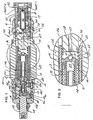
Figure 1 is a side elevation section view of the preferred embodiment of the invention in the form of a vented relief valve. -
Figure 2 is an enlargement of area A ofFigure 1 . -
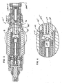
Figure 3 is a side elevation section view of an alternate embodiment of the invention. -
Figure 4 is an enlargement of area B ofFigure 3 . -
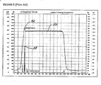
Figure 5 is a typical recorded fluid pressure rise vs. time plot of fluid pressure at the inlet of a conventional pressure valve. -
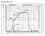
Figure 6 is a recorded fluid pressure versus time plot at the inlet of the pressure valve inU.S. Patent 6039070 . -
Figure 7 is a recorded fluid pressure vs. time plot similar to that ofFigure 6 of the present invention. - The present invention is shown generally in area A of
Figure 1 and area B ofFigure 3 and includes a normallyopen pilot section 46 which may be applied to any valve that can functionally accommodate a sliding pilot piston, e.g. 37 of apilot chamber 24. Thepilot ball 15 starts in a normally-open position before pilot flow enters thepilot piston 37 throughpassage 31. Once this flow is established, thepilot sleeve 14, and thus thepilot piston 37, strokes to load apilot ball 15 against apilot seat 38, compressing the pilot springs 13 and 33 until thepilot sleeve 14 reaches a mechanical stop 49a within the adjustscrew 49 whereupon the maximum pressure setting is reached, or the effective pilot pressure generated by the pilot springs 13 and 33 acting on thepilot ball 15 is equivalent to the system pressure atport 1. - To ensure that the
pilot sleeve 14 consistently returns to the starting position against thescrew 49, areturn spring 35 applies a return force during the entire stroke of thepilot piston 37. Thisreturn spring 35 acts directly on thepilot piston 37 and therefore directly opposes the pilot spring force used to determine the valve setting. - Regardless of the pressure setting applied through the adjustment of the
screw 49, the threshold pressure of the valve remains low. This feature is unlike the prior art in which the threshold pressure adjusts with the maximum set pressure maintaining a constant difference. For any pressure setting of the valve, the initial threshold pressure will be equivalent to the main section bias pressure, i.e., themain section 42 alone determines the threshold pressure of the valve since thepilot section 46 is normally open. - Still referring to
Figures 1 and 2 , the preferred embodiment is shown generally atnumeral 40. This pilot operatedpressure valve 40 generally includes three major components, amain section 42, anelongated pilot section 46 and a pressure adjustsection 48. An elongated outer housing 44 is sealably connected at one end thereof to, and longitudinally extending from, a proximal end of an inlet body 21 of themain section 42. Thepilot section 46 includes acylindrical pilot sleeve 14 which is slidably mounted for limited longitudinal movement within the outer housing 44 and forms the side walls of apilot chamber 24.Pilot sleeve 14 is connected and longitudinally extends from aretainer 26 which is immovably held as part of, and longitudinally extending from, the inlet body 21. The pressure adjustsection 48 is sealably and threadably connected to another end of the outer housing 44 and positioned at another end of thepilot section 46 as shown inFigure 1 . - In general, the
main section 42 is structured to receive pressurized fluid at system pressure. Amain chamber 30 receives metered fluid frominlet port 1 through amain orifice 18 and transfers fluid at a pilot flow rate from themain chamber 30 through a dampingorifice 22 into thepilot chamber 24 through alongitudinal passage 27 in theretainer 26 and throughpassage 31. Themain chamber 30, including amain spring 17, maintains the head ofmain piston 20 in a closed configuration shown inFigure 1 wherein theoutlet port 2 is sealed from fluid communication with theinlet port 1. - The
pilot ball 15 is initially held away from the seat inretainer 26 byreturn spring 35. When the inlet pressure rises above the preset operating pressure of the valve, fluid flow through themain orifice 18 creates sufficient pressure drop across themain orifice 18 to overcome themain spring 17, whereupon pressurized hydraulic fluid will flow directly frominlet port 1 tooutlet port 2 and then to a tank or reservoir at lower or zero pressure. - Pressurized fluid at
inlet port 1 flows at a low pilot flow rate through themain orifice 18 positioned centrally at one end of themain piston 20. The preferred size ofmain orifice 18 is about 0.51 mm (0.02") in diameter. When themain chamber 30 is filled with hydraulic fluid, the pressure inchamber 30 will generally equal that of the system pressure atport 1. The pressurized fluid also flows from themain chamber 30 through the dampingorifice 22 positioned centrally within alongitudinal passage 27 ofretainer 26 and into thepilot chamber 24 throughpassage 31. Thereafter, theentire pilot chamber 24 will be filled with pressurized fluid not exceeding a pre-established pilot chamber pressure of about 15.5 bar (225 psi) determined by a relief spring 10 acting against a relief ball 11 mating elongatedpilot spring seat 12. - As pressurized fluid enters and fills the
pilot chamber 24, air in the chamber, along with a very small amount of pressurized fluid is slowly discharged from adrain orifice 3 formed through the side ofpilot sleeve 14 having a preferred diameter of 0.41 mm (.016"), a diameter sufficiently small to prevent themain piston 20 from opening due only to fluid flow rate through thedrain orifice 3. Aclearance gap 28 is provided between the outer cylindrical surface ofpilot sleeve 14 and the inner cylindrical surface of the outer housing 44 which directs fluid and air discharging from thedrain orifice 3 from the valve throughannular passage 74 topassages retainer 26 and through relief port 6 formed through the outer housing 44 adjacent one end thereof. The flow rate required to load thepilot chamber 24 to keep the valve set at the actual pressure atport 1 is lower than the flow required to move themain piston 20 against themain spring 17. - Pressurized fluid at the relatively low pilot chamber pressure, which cannot exceed that established by a relief spring 10 acting against a relief ball 11 and mating elongated
pilot spring seat 12, additionally flows from thepilot chamber 24 through a control orifice 7 to fill a loading chamber 32. As pilot chamber fluid pressure increases,pilot sleeve 14 overcomes the compression force ofreturn spring 35 and moves towardretainer 26 bringingpilot ball 15 into a seated position on the pilot seat. As thepilot sleeve 14 continues to move toward theretainer 26, the compression force exerted against thepilot spring 13 is increased and thus increases the pressure against thepilot ball 15. By this arrangement of sufficiently large differential area, the operating pressure required within themain chamber 30 to keep thepilot ball 15 unseated increases with pilot spring pressure to adjust the operating pressure of the valve toward its maximum setting. Thus, the minimum operating pressure is established by the pressure bias of themain section 42 when thepilot ball 15 is disengaged from thepilot seat 38 by the contact of flange 34 of relief spring housing 36 within the loading chamber 32 in the position shown, while the maximum operating pressure of the valve is established when the flange 34 andpilot sleeve 14 move to the opposite end of the loading chamber 32 in the direction of arrow B as pilot pressure is increased. When flow to the valve has ceased,pilot piston 37 returns to a starting position by way of compression force from pilot springs 13 and 33 and byreturn spring 35. - Note importantly that the velocity at which the
sleeve 14 moves to a maximum pilot spring preload setting is determined by the rate of fluid flow through the control orifice 7. Moreover, the fluid pressure build-up in thepilot chamber 24 preloads thepilot spring 13 to a pressure setting of thevalve 40 which equals the instantaneous pressure atinlet port 1. - In the preferred embodiment, the effective area for the pilot pressure to act upon is with respect to the
open end surface 29 of thesleeve 14 which defines a differential ring area. The outer diameter of thesleeve 14 is 19.0 mm (.747"); the inner diameter of thesleeve 14 and the outer diameter of theretainer 26 is 12.7 mm (.500"). The differential area, therefore, is about 156.1 sq.mm (.242 sq. inch). That means a pilot chamber pressure of 15.5 bars (225 p.s.i.) exerts a force of about 24.5 kg (54 lbs.) againstpilot piston 37 which is exerted against thepilot ball 15. The pilot ball seat diameter is 2.3 mm (.092") which defines an effective area of 4.3 sq. mm (.0.066 sq. inch.) The pilot spring force of 24.5 kg (54 lbs.) spring force sets the valve at an operating pressure of 564.1 bars (8181 p.s.i.) The pressure in thepilot chamber 24 of 15.5 bars (225 p.s.i.) is additive to this setting so that the theoretical maximum operating pressure setting of the valve is about 579.2 bars (8400 p.s.i.) The actual maximum pressure is limited by the spring load, the pilot springs 13 and 33 apply to thepilot ball 15 at the full stroke of thepilot sleeve 14 at maximum adjustment of the adjustscrew 49. - The details of the structure of the present invention shown in enlarged area A of
Figure 2 , provides the actual "soft start" functional benefits of this invention. When thepilot chamber 24 is substantially filled with pressurized fluid, a force is exerted to unseat relief ball 11 against pilot spring 10 from its seated and sealed position shown. This maximum pilot chamber pressure is preferably about 15.5 bars (225 p.s.i.) The fluid pressure rise in thepilot chamber 24 up to this relief valve ball 11 opening pilot pressure automatically adjusts further compression of thepilot spring 13 as previously described. When the relief ball 11 is unseated when the pilot pressure in thepilot chamber 24 is reached, the pressurized fluid will flow from thepilot chamber 24 through acrosshole 2, along theclearance gap 28 between thepilot sleeve 14 and the outer housing 44 for discharge from the valve through relief port 6. By this arrangement, pilot pressure within thepilot chamber 24 can never exceed the effective preset pilot pressure of about 15.5 bars (225 p.s.i.), made just sufficient to fully preload thepilot spring 13 to its maximum setting wherein flange 34 within loading chamber 32 is moved to the maximum displacement in the direction of arrow B inFigure 2 . Thus, the order of magnitude ratio between operating and pilot pressures is at least about 10 to 1 and preferably as high as about 25 to 1. - To vary the maximum operating pressure setting of the
valve 40, the pressure adjustsection 48 is threadably moveable longitudinally or axially of thevalve 40 to move thesleeve 24 correspondingly. This sleeve movement varies the initial proximity of thepilot ball 15 to the pilot seat and the potential compression load of thepilot chamber spring 13 and the proportionately varied load against thepilot ball 15. - In summary, the present invention limits the rate of pressure rise within an adjustable operating pressure range and further limits the maximum pressure within the valve and the system in which it is connected. Because of this pressure rate increase limitation, pressure spikes or hydraulic shock are also eliminated by the valve. The valve operating pressure at which the valve will open slowly follows the actual pressure at the
inlet port 1. At sudden pressure increase above operating pressure, the valve opens to allow pressurized fluid to discharge throughport 2 until such time as the operating pressure of the valve and the actual inlet pressure are again equal. Moreover, unless the fluid flow into the valve exceeds the capacity of the valve itself, the pressure cannot rise faster than the operating pressure setting of the valve. - As in other pilot operated relief valves, this valve has a low pressure in the pilot chamber. For the soft start mechanism, this is important in three respects:
- a. The maximum pressure drop across the orifice 7 is only 15.5 bars (225 p.s.i.) That means a low consistent flow into the loading chamber 32 which distinguishes this "soft start" valve from other soft start valves. Other valves typically have up to 413.7 bars (6000 p.s.i.) pressure differential across the orifice that controls the shift of the piston or pilot sleeve that determines the valve setting. This rate of flow into the loading chamber through orifice 7 determines the rate at which the setting of the valve changes. The rate of setting change equals the rate of pressure rise at
port 1; - b. The
seals sleeve section 46 see a pressure drop of only 15.5 bars (225 p.s.i.) maximum as compared to up to 413.7 bars (6000 p.s.i.) in other designs, a factor of about 27. This translates into significantly lower friction and lower hysteresis of the present invention over other such prior art valves. - c. The pilot pressure also determines the fluid losses while the valve is active. Assuming that the pressure at
port 1 is within the range where the valve limits the rate of pressure rise, the valve then adjusts it's setting to the actual pressure atport 1. It does so by pressurizing the pilot chamber. A pressurized pilot chamber causes a pilot flow out throughorifice 3. The lower the pressure in the pilot chamber, the lower the fluid losses. -
Figures 5 ,6 and7 depict the functional improvements resulting from the new design feature as compared to two iterations of prior art. The valves used for the comparison were three port ventable relief valves, although the comparison could have been conducted with a variety of other valves (i.e. relief valves, sequence valves, etc.) - Referring first to
Figure 5 , a typical prior art ventable pressure relief valve without the soft start mechanism of the present invention was actually tested.Figure 5 displays system pressure and tank line pressure in a small circuit consisting of a pump and a standard spool-type ventable relief valve. The curves show that when system pressure reaches the valve setting, a pressure spike can be generated in the tank line at 53 as well as in the system at 52. The operating pressure of the valve is shown at 50 to be approximately 193.1 bars (2800 p.s.i.). The test begins with the vented relief valve in the vented state, passing pump flow directly to tank at low pressure. The pressure increase is initiated by blocking the vent, resulting in the pump flow returning to tank at the valve setting 50. Even though pressure increases with the main section of the relief open, the system pressure spikes over the valve setting since the pilot section of the valve is closed until the set pressure is reached, i.e. the valve has no real control over the rate of system pressure increase. - In
Figure 6 , the invention described inU.S. Patent 6,039,070 was subjected to the same fluid pressure inlet condition, this valve having an operating pressure shown at 54 at about 206.8 bars (3000 p.s.i.).Figure 6 displays system pressure at 54 and tank line pressure in a small circuit consisting of a pump and a soft-shift, ventable relief valve (as described by patents of prior art). In this circuit, the rate ofrise 58 in system pressure is limited by the soft-style relief valve, ultimately preventing the typical pressure spike in the system. The pressure spike in the tank line at 57 is reduced as the relief valve begins opening at a pressure lower than theultimate set pressure 54, referred to as thethreshold pressure 56. Thethreshold pressure 56 is depicted on the curve as the point where the system pressure begins to ramp up slowly. Although a pressure spike occurred, it only reached about 113.8 bars (1650 p.s.i.), well below the intended operating pressure at 54. The pressure rise shown at 58 was a gradual increase on a uniformly increasing pressure level basis. This pressure rise 58 occurred after thepilot ball 15 was unseated and the fluid in thepilot chamber 24 as the pilot pressure was rising and adjusting the operating pressure setting of the valve to its maximum. Thus, all system shock and damaging excessive fluid pressure has been eliminated by the '070 invention. - The
present invention 40 or 40' described byFigure 7 , includes a pump and a modified, soft-shift ventable relief valve with a normally open pilot section as above described. In this-case, the threshold pressure is kept to a minimum, by ensuring the pilot stage remains normally open at all possible set pressure adjustments, and thesystem pressure 64 begins a controlled ramp at 66 up as soon as it overcomes the bias spring in the main section. By controlling the rate of pressure rise from such a low pressure, the circuit sees no abrupt changes in the return flow velocity. Therefore, the system pressure spike 68 is once again virtually eliminated, but this time, the tankline pressure spike 69 is virtually eliminated as well. - The basic structure of the present invention as above described may be modified within the intended scope of this invention. One such alternate embodiment shown in
Figs. 1 and 2 is in the form of a vented relief valve achieved by adding another exit port in the outer housing 44,pilot bypass port 3, which is in fluid communication with across passage 46 positioned in fluid communication with thelongitudinal passage 27 between the dampingorifice 22 and thepilot chamber 24. This produces a very low crack or opening pressure of thepiston 20 to exitport 2, depending upon the preload of themain spring 17. Since thisvalve 40 would be vented downstream of the dampingorifice 22, a second pilot relief valve atport 3 cound be used as a remote control. By selectively closingport 3, the setting of the valve rises quickly to the minimum pressure setting as above described. If the pressure at theinlet port 1 rises further, the valve limits the rate of pressure rise again as previously described. -
Figures 3 and 4 display an alternate version of the vented relief valve that vents the system pressure atport 1 through thepilot chamber 24 and outpilot port 3, allowing theinlet section 42 to open a path fromport 1 toport 2. Whileport 3 is connected to tank allowing pilot flow directly back into the reservoir, theinlet section 42 relieves system pressure at a value equivalent to themain spring 17 bias acting on themain piston 20. Pilot pressure seen atport 3 can never exceed the relief setting of the integral relief within thepilot piston 37. Similarly, pressure atport 3 can only decay as quickly as the pressure within thepilot chamber 24. - Still another alternate embodiment of the present invention is in the form of a kick-down relief valve which would incorporate a crosshole extending from the
main chamber 30 to the seating surface of thepiston 20. This embodiment would also eliminate themain orifice 18 so that this valve would open and stay open if the pressure rise at the inlet port exceeds the maximum rate of pressure rise of the valve. The valve would remain open once it is opened because the proposed crosshole in the piston sees the pressure much lower than the pressure atport 1 because of the high rate of fluid flow across the end of the crosshole as fluid moves betweenport 1 andport 2. - Because all of these alternate embodiments incorporate the relief valve arrangement at the opposite end of the pilot chamber as shown and described in
Figure 2 , they also possess this actually realized "soft start" feature with no excessive start-up pressure spikes above the operating pressure of the valve. - A still further alternate embodiment of the invention is in a form which incorporates the essential aspects of this invention to pilot operate an external main stage. To accomplish this, the
main chamber 30 of this invention would be connected to the main chamber of a conventional pilot operated relief valve. The invention itself could be built without the main stage, i.e. without themain piston 20, thespring 17, the dampingorifice 22 and without crossholes in the outer housing 44. - While the instant invention has been shown and described herein in what are conceived to be the most practical and preferred embodiments, it is recognized that departures may be made therefrom within the scope of the invention, which is therefore not to be limited to the details disclosed herein, but is to be afforded the full scope of the claims so as to embrace any and all equivalent apparatus and articles.
Claims (4)
- A pilot operated pressure valve (40) comprising:a main section (42), an elongated cylindrical hollow outer housing (44) sealingly connected at one end thereof to and longitudinally extending from said main section (42), an elongated pilot section (46) having a pilot chamber (24) and being mounted within a cylindrical interior of said outer housing (44) and longitudinally extending at one end thereof from said main section (42), and a pressure adjust section (48) adjustably sealingly connected to another end of said outer housing (44) at another end of said pilot section (46);said main section (42) including an inlet port (1) at one end thereof, an outlet port (2), a retainer (26) sealingly connected to another end of said main section (42), a main piston (20) slidably mounted within said main section (42), and a main spring (17) positioned within and extending longitudinally along a main chamber (30) formed centrally between said retainer (26) and said main piston (20);a head of said main piston (20) defining one end of said main chamber (30) and including a main orifice (18) adjacent said inlet port (1) which allows a relatively small quantity of pressurized fluid at said inlet port (1) to be metered into and fill said main chamber (30);said retainer (26) including a longitudinally extending passage having a pilot seat at one end and a damping orifice (22) at another end thereof, said damping orifice (22) in fluid communication with said main chamber (30) for allowing a relatively small quantity of pressurized fluid in said main chamber (30) to be metered into said pilot chamber (24) from said main chamber (30);said main spring (17) biasingly urging said main piston (20) into sealing engagement against said inlet port (1) until a predetermined inlet pressure equal to a threshold operating pressure of said valve (40) is reached whereupon said main piston (20) is opened by axial movement thereof against said main spring (17) to allow pressurized fluid to enter said inlet port (1) and to exit said valve (40) directly from said outlet port (2);said pilot section (46) including an elongated pilot spring (13) acting at one end thereof within an elongated pilot sleeve (14) of said pilot section (46) against a pilot piston (37) held for sliding translation within said pilot sleeve (14) and supporting a pilot ball (15);said pilot sleeve (14) longitudinally positionable by said pressure adjust section (48) within said outer housing (44) to vary a length of said pilot spring (13) and thus to vary operating pressure; characterised in that:said pilot ball (15) is held from said pilot seat by a return spring (35) acting between said pilot piston (37) and said one end of said retainer (26), said pilot piston (37) moving said pilot ball (15) into a partially sealed position against said pilot seat when pressure in said pilot chamber (24) exceeds a predetermined minimum pressure wherein inlet pressure increases to the operating pressure.
- A pilot operated pressure valve (40) as claimed in claim 1, wherein the pressure adjust section (48) and other end of said outer housing (44) at other end of said pilot section (46) define an adjust chamber therebetween.
- A pilot operated pressure valve (40) as claimed in claim 2:said pilot sleeve (14) including a crosshole closed to fluid communication with said pilot chamber (24) by a relief ball (11) held biasingly, longitudinally slidably positionable within said pilot chamber (24), one end of said pilot piston (37) including a relief orifice which allows a relatively small quantity of pressurized fluid in said pilot chamber (24) to be metered therefrom into fill said adjust chamber;said adjust chamber having a net surface area greater than that of said retainer (26) whereby said pilot sleeve (14) is moveably urged against said pilot spring (13) to vary the valve operating pressure between the threshold pressure and a maximum valve operating pressure.
- A pilot operated pressure valve (40) as claimed in any preceding claim, said retainer (26) including a cross passage in sealed alignment with a pilot bypass port (3) formed through said outer housing (44), said cross passage in fluid communication with said pilot chamber (24) and inlet downstream of said damping orifice (22) for allowing pressurized fluid to exit said valve from said pilot bypass port (3) wherein the operating pressure of said valve is reduced.
Applications Claiming Priority (2)
| Application Number | Priority Date | Filing Date | Title |
|---|---|---|---|
| US66072205P | 2005-03-11 | 2005-03-11 | |
| US11/359,653 US7467642B2 (en) | 2005-03-11 | 2006-02-21 | Soft ventable relief valve |
Publications (3)
| Publication Number | Publication Date |
|---|---|
| EP1701074A2 EP1701074A2 (en) | 2006-09-13 |
| EP1701074A3 EP1701074A3 (en) | 2007-09-12 |
| EP1701074B1 true EP1701074B1 (en) | 2010-10-20 |
Family
ID=36581979
Family Applications (1)
| Application Number | Title | Priority Date | Filing Date |
|---|---|---|---|
| EP20060251297 Active EP1701074B1 (en) | 2005-03-11 | 2006-03-10 | Soft ventable relief valve |
Country Status (4)
| Country | Link |
|---|---|
| US (1) | US7467642B2 (en) |
| EP (1) | EP1701074B1 (en) |
| JP (1) | JP2006250357A (en) |
| DE (1) | DE602006017613D1 (en) |
Families Citing this family (34)
| Publication number | Priority date | Publication date | Assignee | Title |
|---|---|---|---|---|
| EP1923215A1 (en) * | 2006-11-14 | 2008-05-21 | Nederlandse Organisatie voor toegepast-natuurwetenschappelijk Onderzoek TNO | Constant flow high pressure printing system |
| KR100826627B1 (en) * | 2007-03-27 | 2008-05-02 | 볼보 컨스트럭션 이키프먼트 홀딩 스웨덴 에이비 | Relief valve of heavy equipment |
| US9360025B2 (en) | 2010-07-22 | 2016-06-07 | Maradyne Corporation | Hydraulic soft start system |
| US9239065B2 (en) | 2010-07-22 | 2016-01-19 | Maradyne Corporation | Hydraulic soft start system |
| US8578713B2 (en) | 2010-07-22 | 2013-11-12 | Maradyne Corporation | Hydraulic soft start system |
| JP5775368B2 (en) * | 2011-06-08 | 2015-09-09 | 川崎重工業株式会社 | Relief valve |
| US9273702B2 (en) | 2011-10-21 | 2016-03-01 | Sun Hydraulics Corporation | Dynamically adjusting counterbalance valve |
| US20130291964A1 (en) * | 2012-04-11 | 2013-11-07 | Parker-Hannifin Corporation | Proportional normally closed pilot pressure control valve |
| DE102013014673A1 (en) * | 2013-09-04 | 2015-03-05 | Hydac Fluidtechnik Gmbh | Load-holding valve |
| US9850919B2 (en) | 2014-09-16 | 2017-12-26 | Sun Hydraulics Corporation | Counterbalance valve with dual or triple pilot ratio |
| US10437269B1 (en) * | 2017-10-06 | 2019-10-08 | Sun Hydraulics, Llc | Electrohydraulic counterbalance and pressure relief valve |
| US10436344B2 (en) * | 2017-10-30 | 2019-10-08 | Sun Hydraulics, Llc | Pressure-balanced push-type manual actuation mechanism for a valve |
| CN108180185B (en) * | 2017-11-08 | 2019-11-15 | 中国航空工业集团公司金城南京机电液压工程研究中心 | A kind of pilot-operated type deadweight safety valve |
| US10794510B1 (en) | 2017-12-20 | 2020-10-06 | Sun Hydraulics, Llc | Electrohydraulic counterbalance and pressure relief valve |
| US10495117B1 (en) | 2018-04-17 | 2019-12-03 | Sun Hydraulics, Llc | Electrohydraulic counterbalance and pressure relief valve |
| US10663066B2 (en) | 2018-08-03 | 2020-05-26 | Sun Hydraulics, Llc | Methods and assemblies for retaining an internal component of a valve within an external component thereof using a retention O-ring and groove geometry |
| US10774853B2 (en) | 2018-09-18 | 2020-09-15 | Sun Hydraulics, Llc | Electrohydraulic valve normally operating in fluid flow-blocking mode and configured to operate in pressure relief mode when actuated |
| US10557483B1 (en) | 2018-09-18 | 2020-02-11 | Sun Hydraulics, Llc | Electrohydraulic valve normally operating in pressure relief mode and configured to operate in ventable mode when actuated |
| US10533584B1 (en) * | 2018-09-18 | 2020-01-14 | Sun Hydraulics, Llc | Electrohydraulic normally-open ventable valve configured to operate in pressure relief mode when actuated |
| US10570932B1 (en) | 2018-09-18 | 2020-02-25 | Sun Hydraulics, Llc | Electrohydraulic valve normally operating in pressure relief mode and configured to block fluid flow when actuated |
| US10626892B1 (en) * | 2018-12-10 | 2020-04-21 | Sun Hydraulics, Llc | Proportional valve for fluid flow control |
| US10662979B1 (en) * | 2018-12-10 | 2020-05-26 | Sun Hydraulics, Llc | Proportional valve for fluid flow control and generation of load-sense signal |
| US10683879B1 (en) | 2019-01-22 | 2020-06-16 | Sun Hydraulics, Llc | Two-port electrohydraulic counterbalance valve |
| US10775812B1 (en) * | 2019-01-22 | 2020-09-15 | Sun Hydraulics, Llc | Inverse proportional pressure relief valve |
| US11000863B2 (en) * | 2019-03-26 | 2021-05-11 | Pentair Flow Technologies, Llc | Push valve assembly and method |
| US10969801B2 (en) * | 2019-06-17 | 2021-04-06 | Sun Hydraulics, Llc | Proportional flow control and counterbalance valve having single seat configuration |
| US10969800B2 (en) * | 2019-06-17 | 2021-04-06 | Sun Hydraulics, Llc | Proportional flow control valve with counterbalance valve integrated therewith |
| US11009896B2 (en) * | 2019-07-03 | 2021-05-18 | Sun Hydraulics, Llc | Proporational flow control valve and pilot-operated check valve integrated therewith |
| US11549525B2 (en) * | 2020-01-24 | 2023-01-10 | Husco International, Inc. | Electronically adjustable pressure compensated flow control with pressure limiting relief valve |
| US11353127B2 (en) * | 2020-04-28 | 2022-06-07 | Sun Hydraulics, Llc | Vented counterbalance valve with two setting springs in parallel |
| GB2605755B (en) * | 2021-02-25 | 2024-04-10 | Jb Valves Ltd | Valve Apparatus |
| US11384857B1 (en) * | 2021-07-02 | 2022-07-12 | Sun Hydraulics, Llc | Bidirectional pressure relief valve |
| CN113389933B (en) * | 2021-07-29 | 2022-08-09 | 四川长仪油气集输设备股份有限公司 | Multifunctional pilot operated safety valve |
| CN117307737B (en) * | 2023-11-30 | 2024-02-13 | 佛山市长茂液压机械制造有限公司 | Active adjustable cartridge valve |
Family Cites Families (9)
| Publication number | Priority date | Publication date | Assignee | Title |
|---|---|---|---|---|
| DE3318246A1 (en) * | 1983-05-19 | 1984-11-22 | Mannesmann Rexroth GmbH, 8770 Lohr | Pressure limiting valve |
| US4795129A (en) * | 1985-01-29 | 1989-01-03 | Clark Richard J | Normally closed fluid switching logic element |
| WO1986004657A1 (en) * | 1985-02-08 | 1986-08-14 | Dibartolo Ernest A | Direct-acting, differential piston relief valve |
| US4653527A (en) * | 1985-10-21 | 1987-03-31 | Modular Controls Corporation | Pressure relief valve |
| US4834135A (en) * | 1988-11-01 | 1989-05-30 | Sun Hydraulics Corp. | Pressure control valve |
| US5050636A (en) * | 1990-10-17 | 1991-09-24 | Kawasaki Jukogyo Kabushiki Kaisha | Relief valve |
| US5381823A (en) * | 1994-02-14 | 1995-01-17 | Sun Hydraulics | Hydraulic pressure control valve |
| US6039070A (en) * | 1998-11-09 | 2000-03-21 | Sun Hydraulics Corp. | Pilot operated pressure valve |
| US6640830B2 (en) * | 2001-12-12 | 2003-11-04 | Sun Hydraulics Corp. | Pilot operated pressure valve |
-
2006
- 2006-02-21 US US11/359,653 patent/US7467642B2/en not_active Expired - Fee Related
- 2006-03-10 DE DE200660017613 patent/DE602006017613D1/en active Active
- 2006-03-10 EP EP20060251297 patent/EP1701074B1/en active Active
- 2006-03-13 JP JP2006066994A patent/JP2006250357A/en active Pending
Also Published As
| Publication number | Publication date |
|---|---|
| DE602006017613D1 (en) | 2010-12-02 |
| US7467642B2 (en) | 2008-12-23 |
| US20060201554A1 (en) | 2006-09-14 |
| JP2006250357A (en) | 2006-09-21 |
| EP1701074A2 (en) | 2006-09-13 |
| EP1701074A3 (en) | 2007-09-12 |
Similar Documents
| Publication | Publication Date | Title |
|---|---|---|
| EP1701074B1 (en) | Soft ventable relief valve | |
| US6039070A (en) | Pilot operated pressure valve | |
| US6640830B2 (en) | Pilot operated pressure valve | |
| US5381823A (en) | Hydraulic pressure control valve | |
| KR100764119B1 (en) | Pilot poppet type relief valve | |
| US6745992B2 (en) | Pilot operated control valve having a poppet with integral pressure compensating mechanism | |
| US5065789A (en) | Back pressure regulating valve for ultra high pressures | |
| US4201522A (en) | Boost-retarding device for electromagnetic plunger pump and the like | |
| US6601602B2 (en) | Pressure-control valve | |
| US5490539A (en) | Pressure regulator for maintaining a stable flow level of a fluid | |
| US4119016A (en) | Hydraulic control device | |
| JPS6170201A (en) | Hydraulic self-holding type two-position changeover valve | |
| JPH09178025A (en) | Two stage type electric hydraulic pressure control valve | |
| US5971353A (en) | Dump/stop valve for surface controlled subsurface safety valve | |
| WO2004042192A1 (en) | Monitoring valve, rock drilling apparatus and a method for controlling at least two hydraulic actuators to such a monitoring valve and rock drilling apparatus | |
| KR20030017324A (en) | Relief valve and hydraulic device having the relief valve | |
| EP0611687B1 (en) | Antilock modulator | |
| JP3054996B2 (en) | safety valve | |
| US6892709B2 (en) | Pressure regulator | |
| US4665942A (en) | Hydraulic pressure fuse | |
| US6957660B2 (en) | Pressure relief valve with bidirectional damping | |
| CA2079137C (en) | Two-stage valve | |
| JP2007239961A (en) | Soft bent relief valve | |
| JP2004084671A (en) | Device for controlling at least one gas exchange valve of internal combustion engine | |
| CN213655278U (en) | Control device and work apparatus |
Legal Events
| Date | Code | Title | Description |
|---|---|---|---|
| PUAI | Public reference made under article 153(3) epc to a published international application that has entered the european phase |
Free format text: ORIGINAL CODE: 0009012 |
|
| AK | Designated contracting states |
Kind code of ref document: A2 Designated state(s): AT BE BG CH CY CZ DE DK EE ES FI FR GB GR HU IE IS IT LI LT LU LV MC NL PL PT RO SE SI SK TR |
|
| AX | Request for extension of the european patent |
Extension state: AL BA HR MK YU |
|
| PUAL | Search report despatched |
Free format text: ORIGINAL CODE: 0009013 |
|
| AK | Designated contracting states |
Kind code of ref document: A3 Designated state(s): AT BE BG CH CY CZ DE DK EE ES FI FR GB GR HU IE IS IT LI LT LU LV MC NL PL PT RO SE SI SK TR |
|
| AX | Request for extension of the european patent |
Extension state: AL BA HR MK YU |
|
| 17P | Request for examination filed |
Effective date: 20080312 |
|
| AKX | Designation fees paid |
Designated state(s): CH DE GB IT LI |
|
| GRAP | Despatch of communication of intention to grant a patent |
Free format text: ORIGINAL CODE: EPIDOSNIGR1 |
|
| GRAS | Grant fee paid |
Free format text: ORIGINAL CODE: EPIDOSNIGR3 |
|
| GRAA | (expected) grant |
Free format text: ORIGINAL CODE: 0009210 |
|
| AK | Designated contracting states |
Kind code of ref document: B1 Designated state(s): CH DE GB IT LI |
|
| REG | Reference to a national code |
Ref country code: GB Ref legal event code: FG4D |
|
| REG | Reference to a national code |
Ref country code: CH Ref legal event code: EP |
|
| REF | Corresponds to: |
Ref document number: 602006017613 Country of ref document: DE Date of ref document: 20101202 Kind code of ref document: P |
|
| PLBE | No opposition filed within time limit |
Free format text: ORIGINAL CODE: 0009261 |
|
| STAA | Information on the status of an ep patent application or granted ep patent |
Free format text: STATUS: NO OPPOSITION FILED WITHIN TIME LIMIT |
|
| 26N | No opposition filed |
Effective date: 20110721 |
|
| REG | Reference to a national code |
Ref country code: CH Ref legal event code: PL |
|
| REG | Reference to a national code |
Ref country code: DE Ref legal event code: R097 Ref document number: 602006017613 Country of ref document: DE Effective date: 20110721 |
|
| GBPC | Gb: european patent ceased through non-payment of renewal fee |
Effective date: 20110310 |
|
| PG25 | Lapsed in a contracting state [announced via postgrant information from national office to epo] |
Ref country code: IT Free format text: LAPSE BECAUSE OF FAILURE TO SUBMIT A TRANSLATION OF THE DESCRIPTION OR TO PAY THE FEE WITHIN THE PRESCRIBED TIME-LIMIT Effective date: 20101020 |
|
| PG25 | Lapsed in a contracting state [announced via postgrant information from national office to epo] |
Ref country code: LI Free format text: LAPSE BECAUSE OF NON-PAYMENT OF DUE FEES Effective date: 20110331 Ref country code: CH Free format text: LAPSE BECAUSE OF NON-PAYMENT OF DUE FEES Effective date: 20110331 |
|
| PG25 | Lapsed in a contracting state [announced via postgrant information from national office to epo] |
Ref country code: GB Free format text: LAPSE BECAUSE OF NON-PAYMENT OF DUE FEES Effective date: 20110310 |
|
| REG | Reference to a national code |
Ref country code: DE Ref legal event code: R082 Ref document number: 602006017613 Country of ref document: DE Representative=s name: KNH PATENTANWAELTE KAHLHOEFER NEUMANN ROESSLER, DE Ref country code: DE Ref legal event code: R082 Ref document number: 602006017613 Country of ref document: DE Representative=s name: KNH PATENTANWAELTE NEUMANN HEINE TARUTTIS PART, DE |
|
| REG | Reference to a national code |
Ref country code: DE Ref legal event code: R082 Ref document number: 602006017613 Country of ref document: DE Representative=s name: KEENWAY PATENTANWAELTE NEUMANN HEINE TARUTTIS , DE Ref country code: DE Ref legal event code: R082 Ref document number: 602006017613 Country of ref document: DE Representative=s name: KNH PATENTANWAELTE NEUMANN HEINE TARUTTIS PART, DE Ref country code: DE Ref legal event code: R081 Ref document number: 602006017613 Country of ref document: DE Owner name: SUN HYDRAULICS, LLC, SARASOTA, US Free format text: FORMER OWNER: SUN HYDRAULICS CORP., SARASOTA, FLA., US |
|
| PGFP | Annual fee paid to national office [announced via postgrant information from national office to epo] |
Ref country code: DE Payment date: 20240220 Year of fee payment: 19 |